EP2898563B1 - Fuel cell stack - Google Patents
Fuel cell stack Download PDFInfo
- Publication number
- EP2898563B1 EP2898563B1 EP13779328.7A EP13779328A EP2898563B1 EP 2898563 B1 EP2898563 B1 EP 2898563B1 EP 13779328 A EP13779328 A EP 13779328A EP 2898563 B1 EP2898563 B1 EP 2898563B1
- Authority
- EP
- European Patent Office
- Prior art keywords
- coolant
- fuel cell
- cell stack
- feed inlet
- inlet manifold
- Prior art date
- Legal status (The legal status is an assumption and is not a legal conclusion. Google has not performed a legal analysis and makes no representation as to the accuracy of the status listed.)
- Active
Links
- 239000000446 fuel Substances 0.000 title claims description 126
- 239000002826 coolant Substances 0.000 claims description 198
- 239000012530 fluid Substances 0.000 claims description 36
- 239000012212 insulator Substances 0.000 claims description 5
- 210000004027 cell Anatomy 0.000 description 102
- XLYOFNOQVPJJNP-UHFFFAOYSA-N water Substances O XLYOFNOQVPJJNP-UHFFFAOYSA-N 0.000 description 15
- 239000007800 oxidant agent Substances 0.000 description 9
- 230000001590 oxidative effect Effects 0.000 description 9
- 238000001816 cooling Methods 0.000 description 5
- 239000008367 deionised water Substances 0.000 description 5
- 239000012528 membrane Substances 0.000 description 5
- 239000000498 cooling water Substances 0.000 description 4
- 230000003134 recirculating effect Effects 0.000 description 4
- 230000007797 corrosion Effects 0.000 description 3
- 238000005260 corrosion Methods 0.000 description 3
- 239000000243 solution Substances 0.000 description 3
- 230000000712 assembly Effects 0.000 description 2
- 238000000429 assembly Methods 0.000 description 2
- 230000008901 benefit Effects 0.000 description 2
- 239000012895 dilution Substances 0.000 description 2
- 238000010790 dilution Methods 0.000 description 2
- 239000001257 hydrogen Substances 0.000 description 2
- 229910052739 hydrogen Inorganic materials 0.000 description 2
- 238000002347 injection Methods 0.000 description 2
- 239000007924 injection Substances 0.000 description 2
- 150000002500 ions Chemical class 0.000 description 2
- 241000894006 Bacteria Species 0.000 description 1
- UFHFLCQGNIYNRP-UHFFFAOYSA-N Hydrogen Chemical compound [H][H] UFHFLCQGNIYNRP-UHFFFAOYSA-N 0.000 description 1
- WYTGDNHDOZPMIW-RCBQFDQVSA-N alstonine Natural products C1=CC2=C3C=CC=CC3=NC2=C2N1C[C@H]1[C@H](C)OC=C(C(=O)OC)[C@H]1C2 WYTGDNHDOZPMIW-RCBQFDQVSA-N 0.000 description 1
- QVGXLLKOCUKJST-UHFFFAOYSA-N atomic oxygen Chemical compound [O] QVGXLLKOCUKJST-UHFFFAOYSA-N 0.000 description 1
- 230000015572 biosynthetic process Effects 0.000 description 1
- 210000000170 cell membrane Anatomy 0.000 description 1
- 239000007795 chemical reaction product Substances 0.000 description 1
- 230000000052 comparative effect Effects 0.000 description 1
- 239000000356 contaminant Substances 0.000 description 1
- 239000012809 cooling fluid Substances 0.000 description 1
- 229910021641 deionized water Inorganic materials 0.000 description 1
- 238000013461 design Methods 0.000 description 1
- 238000010438 heat treatment Methods 0.000 description 1
- -1 hydrogen ions Chemical class 0.000 description 1
- 239000012535 impurity Substances 0.000 description 1
- 238000010348 incorporation Methods 0.000 description 1
- 238000012423 maintenance Methods 0.000 description 1
- 239000002184 metal Substances 0.000 description 1
- 238000000034 method Methods 0.000 description 1
- 238000012544 monitoring process Methods 0.000 description 1
- 239000001301 oxygen Substances 0.000 description 1
- 229910052760 oxygen Inorganic materials 0.000 description 1
- 230000000737 periodic effect Effects 0.000 description 1
- 238000010926 purge Methods 0.000 description 1
- 239000000376 reactant Substances 0.000 description 1
- 238000012546 transfer Methods 0.000 description 1
Images

Classifications
-
- H—ELECTRICITY
- H01—ELECTRIC ELEMENTS
- H01M—PROCESSES OR MEANS, e.g. BATTERIES, FOR THE DIRECT CONVERSION OF CHEMICAL ENERGY INTO ELECTRICAL ENERGY
- H01M8/00—Fuel cells; Manufacture thereof
- H01M8/04—Auxiliary arrangements, e.g. for control of pressure or for circulation of fluids
- H01M8/04298—Processes for controlling fuel cells or fuel cell systems
- H01M8/04313—Processes for controlling fuel cells or fuel cell systems characterised by the detection or assessment of variables; characterised by the detection or assessment of failure or abnormal function
- H01M8/0438—Pressure; Ambient pressure; Flow
- H01M8/04417—Pressure; Ambient pressure; Flow of the coolant
-
- H—ELECTRICITY
- H01—ELECTRIC ELEMENTS
- H01M—PROCESSES OR MEANS, e.g. BATTERIES, FOR THE DIRECT CONVERSION OF CHEMICAL ENERGY INTO ELECTRICAL ENERGY
- H01M8/00—Fuel cells; Manufacture thereof
- H01M8/04—Auxiliary arrangements, e.g. for control of pressure or for circulation of fluids
- H01M8/04007—Auxiliary arrangements, e.g. for control of pressure or for circulation of fluids related to heat exchange
- H01M8/04029—Heat exchange using liquids
-
- H—ELECTRICITY
- H01—ELECTRIC ELEMENTS
- H01M—PROCESSES OR MEANS, e.g. BATTERIES, FOR THE DIRECT CONVERSION OF CHEMICAL ENERGY INTO ELECTRICAL ENERGY
- H01M8/00—Fuel cells; Manufacture thereof
- H01M8/02—Details
- H01M8/0202—Collectors; Separators, e.g. bipolar separators; Interconnectors
-
- H—ELECTRICITY
- H01—ELECTRIC ELEMENTS
- H01M—PROCESSES OR MEANS, e.g. BATTERIES, FOR THE DIRECT CONVERSION OF CHEMICAL ENERGY INTO ELECTRICAL ENERGY
- H01M8/00—Fuel cells; Manufacture thereof
- H01M8/02—Details
- H01M8/0202—Collectors; Separators, e.g. bipolar separators; Interconnectors
- H01M8/0267—Collectors; Separators, e.g. bipolar separators; Interconnectors having heating or cooling means, e.g. heaters or coolant flow channels
-
- H—ELECTRICITY
- H01—ELECTRIC ELEMENTS
- H01M—PROCESSES OR MEANS, e.g. BATTERIES, FOR THE DIRECT CONVERSION OF CHEMICAL ENERGY INTO ELECTRICAL ENERGY
- H01M8/00—Fuel cells; Manufacture thereof
- H01M8/04—Auxiliary arrangements, e.g. for control of pressure or for circulation of fluids
- H01M8/04007—Auxiliary arrangements, e.g. for control of pressure or for circulation of fluids related to heat exchange
- H01M8/04067—Heat exchange or temperature measuring elements, thermal insulation, e.g. heat pipes, heat pumps, fins
-
- H—ELECTRICITY
- H01—ELECTRIC ELEMENTS
- H01M—PROCESSES OR MEANS, e.g. BATTERIES, FOR THE DIRECT CONVERSION OF CHEMICAL ENERGY INTO ELECTRICAL ENERGY
- H01M8/00—Fuel cells; Manufacture thereof
- H01M8/04—Auxiliary arrangements, e.g. for control of pressure or for circulation of fluids
- H01M8/04298—Processes for controlling fuel cells or fuel cell systems
- H01M8/04694—Processes for controlling fuel cells or fuel cell systems characterised by variables to be controlled
- H01M8/04746—Pressure; Flow
- H01M8/04768—Pressure; Flow of the coolant
-
- H—ELECTRICITY
- H01—ELECTRIC ELEMENTS
- H01M—PROCESSES OR MEANS, e.g. BATTERIES, FOR THE DIRECT CONVERSION OF CHEMICAL ENERGY INTO ELECTRICAL ENERGY
- H01M8/00—Fuel cells; Manufacture thereof
- H01M8/24—Grouping of fuel cells, e.g. stacking of fuel cells
- H01M8/241—Grouping of fuel cells, e.g. stacking of fuel cells with solid or matrix-supported electrolytes
-
- H—ELECTRICITY
- H01—ELECTRIC ELEMENTS
- H01M—PROCESSES OR MEANS, e.g. BATTERIES, FOR THE DIRECT CONVERSION OF CHEMICAL ENERGY INTO ELECTRICAL ENERGY
- H01M8/00—Fuel cells; Manufacture thereof
- H01M8/24—Grouping of fuel cells, e.g. stacking of fuel cells
- H01M8/2465—Details of groupings of fuel cells
- H01M8/2483—Details of groupings of fuel cells characterised by internal manifolds
-
- H—ELECTRICITY
- H01—ELECTRIC ELEMENTS
- H01M—PROCESSES OR MEANS, e.g. BATTERIES, FOR THE DIRECT CONVERSION OF CHEMICAL ENERGY INTO ELECTRICAL ENERGY
- H01M8/00—Fuel cells; Manufacture thereof
- H01M8/10—Fuel cells with solid electrolytes
- H01M2008/1095—Fuel cells with polymeric electrolytes
-
- H—ELECTRICITY
- H01—ELECTRIC ELEMENTS
- H01M—PROCESSES OR MEANS, e.g. BATTERIES, FOR THE DIRECT CONVERSION OF CHEMICAL ENERGY INTO ELECTRICAL ENERGY
- H01M8/00—Fuel cells; Manufacture thereof
- H01M8/04—Auxiliary arrangements, e.g. for control of pressure or for circulation of fluids
- H01M8/04007—Auxiliary arrangements, e.g. for control of pressure or for circulation of fluids related to heat exchange
- H01M8/04044—Purification of heat exchange media
-
- H—ELECTRICITY
- H01—ELECTRIC ELEMENTS
- H01M—PROCESSES OR MEANS, e.g. BATTERIES, FOR THE DIRECT CONVERSION OF CHEMICAL ENERGY INTO ELECTRICAL ENERGY
- H01M8/00—Fuel cells; Manufacture thereof
- H01M8/04—Auxiliary arrangements, e.g. for control of pressure or for circulation of fluids
- H01M8/04298—Processes for controlling fuel cells or fuel cell systems
- H01M8/04313—Processes for controlling fuel cells or fuel cell systems characterised by the detection or assessment of variables; characterised by the detection or assessment of failure or abnormal function
- H01M8/0444—Concentration; Density
- H01M8/04485—Concentration; Density of the coolant
-
- Y—GENERAL TAGGING OF NEW TECHNOLOGICAL DEVELOPMENTS; GENERAL TAGGING OF CROSS-SECTIONAL TECHNOLOGIES SPANNING OVER SEVERAL SECTIONS OF THE IPC; TECHNICAL SUBJECTS COVERED BY FORMER USPC CROSS-REFERENCE ART COLLECTIONS [XRACs] AND DIGESTS
- Y02—TECHNOLOGIES OR APPLICATIONS FOR MITIGATION OR ADAPTATION AGAINST CLIMATE CHANGE
- Y02E—REDUCTION OF GREENHOUSE GAS [GHG] EMISSIONS, RELATED TO ENERGY GENERATION, TRANSMISSION OR DISTRIBUTION
- Y02E60/00—Enabling technologies; Technologies with a potential or indirect contribution to GHG emissions mitigation
- Y02E60/30—Hydrogen technology
- Y02E60/50—Fuel cells
Definitions
- the present invention relates to electrochemical fuel cells disposed in a stack formation, and in particular to cooling systems for such fuel cell stacks.
- a common type of electrochemical fuel cell for reacting hydrogen and oxygen comprises a polymeric ion transfer membrane, also known as a proton exchange membrane (PEM), within a membrane-electrode assembly (MEA), with fuel and air being passed over respective sides of the membrane.
- Protons i.e. hydrogen ions
- MEA membrane-electrode assembly
- a stack is formed comprising a number of MEAs electrically arranged in series. Each MEA is provided with separate anode and cathode fluid flow paths. The anode and cathode fluid flow paths respectively deliver fuel and oxidant to the membrane.
- the fuel cell stack is typically in the form of a block comprising numerous individual fuel cell plates held together by end plates at either end of the stack.
- a fuel cell stack requires cooling once an operating temperature has been reached, to avoid damage to the fuel cells. Cooling may be achieved at least in part by the delivery of water to individual cells in the stack in either the anode fluid flow paths (which serves to hydrate the anode) and/or in the cathode fluid flow path which combines with reactant water. In each case, evaporative cooling of the fuel cells can occur.
- the cooling water is injected into the anode or cathode fluid flow channels from one or more common manifolds extending down the side of the fuel cell stack.
- a potential problem arises from the flow rates of water within such manifolds. Water may be fed into an inlet at one end of an inlet manifold, from which it is fed into individual cells in the stack. This results in a reduction in water flow rate along the manifold away from the inlet.
- the flow rate in the manifold at the first cell will be 100 ml/min; after the 50th cell the flow rate in the manifold may be approximately 50 ml/min, and at the final cell the flow rate in the manifold may be only 1 ml/min.
- Such very low flows, e.g. 1 ml/min, in the manifold can lead to reliability problems for a fuel cell stack. Problems can occur in regions of stagnant or near stagnant flow due to increased corrosion risk, particularly when using deionised water, and an increased risk of build up of bacteria.
- deionised water of a high grade for example, 18 M ⁇
- the voltage difference between each cell due to the conductivity of the water can be considered to be sufficiently low so as not to exacerbate corrosion in the stack.
- the conductivity of the water is likely to increase due to a number of factors, including CO 2 absorbed from the atmosphere, and washout of ions and impurities or contaminants from the fuel cell membranes and from metallic components in the fuel cell stack.
- the voltage difference across the injected water will increase, thus providing an environment where cell corrosion is more likely to occur.
- the flow rate of cooling water in the inlet manifold is likely to be at a minimum, and ionic deposits from the cooling water are more likely to form and attack / corrode metal components such as flow plates in the fuel cell stack.
- the invention provides a fuel cell stack assembly comprising: a plurality of fuel cells each having a fluid coolant conduit; and
- Each discharge conduit may comprise an additional plate extending across the stack and disposed at the one end of the fuel cell stack.
- the additional plate may comprise a heater plate, a current collector plate or an insulator plate.
- the first discharge conduit may comprise a conduit of increased flow impedance compared to the coolant feed inlet manifold, such that a coolant flow rate from the coolant feed inlet manifold to the first discharge conduit is within a predetermined flow rate range.
- the second discharge conduit is located at an opposite end of the coolant feed inlet manifold to the first discharge conduit.
- the second discharge conduit may comprise an additional plate extending across the stack and disposed at the opposite end of the fuel cell stack.
- the additional plate may comprise a heater plate, a current collector plate or an insulator plate.
- the first discharge conduit may comprise a recirculation path coupled to the coolant inlet for the recirculation of coolant to the coolant feed inlet manifold.
- the fuel cell stack assembly may include a coolant resistivity monitor configured to determine the resistivity of coolant passing through the recirculation path.
- the first discharge conduit may be coupled to an external coolant sump or tank.
- a flow control assembly may be coupled to the first discharge conduit configured to control the flow of coolant fluid from the coolant feed inlet manifold to the first discharge conduit.
- the flow control assembly may comprise a variable flow restrictor.
- the end of the fuel cell stack with the first discharge conduit may be an electrically positive end of the fuel cell stack.
- An outlet manifold may be coupled to each fluid coolant conduit of the plurality of fuel cells for receiving coolant from each fuel cell. Each discharge conduit may form part of the outlet manifold.
- the various examples described below provide excess coolant injected into a coolant feed inlet manifold.
- the coolant may be water, preferably deionized water.
- a portion of the injected coolant passes to fluid coolant conduits in the fuel cells in the fuel cell stack.
- Another portion, described as the excess coolant exits the coolant feed inlet manifold via a discharge conduit without passing through the fuel cells.
- the examples described herein do not necessarily require the use of additional valve, pump and/or controllers in order to achieve the flow rates required to mitigate coolant stagnation problems.
- the present invention advantageously provides improved fuel cell stack assemblies without the logistical considerations, extra engineering, maintenance considerations and increased cost of including additional components such as valves.
- the invention allows the incorporation of such valves if required for further control of the coolant fluid to/from the fuel cells.
- embodiments described herein provide a solution to the problem of low coolant flow rates and coolant stagnation which can readily be combined with other design variations for fuel cell stacks, thereby contributing to a modular fuel cell system with flexibility for tailoring depending on the particular conditions required.
- FIG. 1 shows a schematic side view of a fuel cell stack 10.
- the stack 10 comprises a plurality of fuel cells 11, each of which has an anode fluid flow path for delivering fuel to an anode surface of a membrane-electrode assembly and a cathode fluid flow path for delivering oxidant to a cathode surface of a membrane-electrode assembly.
- the fuel cells are held in a stack arrangement by way of end plates 12, 13 in a known manner.
- the anode fluid flow paths or the cathode fluid flow paths are provided with coolant injection for evaporative cooling of the fuel cell stack by way of a coolant feed inlet manifold 14, which extends down the length of the stack 10 between a coolant inlet 15 and a discharge conduit 16 at opposing ends of the coolant feed inlet manifold 14.
- the coolant feed inlet manifold 14 may be described as a coolant / water delivery manifold or gallery.
- coolant flows into the manifold from the coolant inlet 15, then into each of the fluid flow paths of the separate fuel cells 11.
- the coolant combines with the fuel or oxidant flow at some point between the coolant feed inlet manifold 14 and flow channels in the individual fuel cells 11. These flow channels extend across the active surfaces of the fuel cells 11.
- the fuel and oxidant may be introduced into the individual cells 11 using a separate fuel manifold and a separate oxidant manifold using known techniques.
- unused fuel or oxidant may pass out of the fuel cells into an outlet manifold 17 and, in some examples, from there to one or more exhaust ports / outlets 18, 19.
- An outlet manifold 17 is not necessarily required for the anode fluid flow paths if all fuel is consumed at the active surfaces of the fuel cells 11, particularly if coolant injection is not provided on the anode sides of the fuel cells 11, although an anode exhaust line may be provided for periodic purging.
- an outlet manifold 17 is shown coupled to each fluid coolant conduit of the plurality of fuel cells 11 for discharge of at least coolant from each fuel cell 11.
- FIG 1 shows a discharge conduit 16 for excess coolant 20 to pass out of the coolant feed inlet manifold 14 without passing through the fluid coolant conduits of the fuel cells 11.
- the discharge conduit 16 of figure 1 may be described as an external coolant drain.
- Figure 1 thus shows a fuel cell stack assembly 10 comprising a plurality of fuel cells 11 each having a fluid coolant conduit, and a coolant feed inlet manifold 14 having a coolant inlet 15.
- the coolant feed inlet manifold 14 is coupled to each fluid coolant conduit of the fuel cells 11 for distribution of coolant to each fuel cell.
- the coolant feed inlet manifold 14 further comprises a discharge conduit 16 located at one end of the coolant feed inlet manifold 14.
- the discharge conduit 16 is configured to discharge excess coolant 20 from the coolant feed inlet manifold 14.
- excess coolant may be injected via the coolant inlet 15 to the fuel cell stack 10 and the portion of the manifold furthest from the coolant inlet 15 need not be subject to very low coolant flow rates.
- a coolant fluid flow may be provided at the coolant inlet 15 to the coolant feed inlet manifold 14 such that there is sufficient flow through the manifold, even at the end of the fuel cell stack 10 furthest from the coolant inlet 14, to avoid or mitigate coolant fluid stagnation which can lead to problems as described earlier. Excess coolant 20, which does not pass through the fuel cells 11, exits the coolant feed inlet manifold 14 by the discharge conduit 16.
- FIG. 2 shows a fuel cell stack assembly 10 comprising a plurality of fuel cells 11 each having a fluid coolant conduit, and a coolant feed inlet manifold 14 having a coolant inlet 15 at one end of the stack.
- the coolant feed inlet manifold 14 comprises a discharge conduit 16 located at the other end of the stack, and the discharge conduit 16 is configured to discharge excess coolant 20 from the coolant feed inlet manifold 14.
- the discharge conduit 16 passes from the end of the coolant feed inlet manifold 14 opposite the coolant inlet 15, across the fuel cell stack 10, parallel to the fuel cell conduits, to the side of the stack opposite to the coolant feel inlet manifold 14, before passing out through an outlet manifold 17.
- the discharge conduit 16 is shown to form part of the outlet manifold 17, although this need not be the case and the discharge conduit 16 may pass out from the fuel cell stack via a path separate from the outlet manifold 17.
- the discharge conduit 16 may comprise or be formed within an additional plate 21 extending across the width of the stack, parallel to the fuel cells, and disposed at the end of the fuel cell stack 10.
- This additional plate 21 could be a heater plate or a current collector plate or an insulator plate adjacent to the end plate 13.
- the discharge conduit 16 in figure 2 may be described as an internal coolant drain.
- the discharge conduit 16 may be formed within the additional plate 21 to allow the passage of excess coolant from the side of the fuel cell stack opposite the coolant inlet 15. If the discharge conduit 16 is included within a heater plate, the discharge conduit 16 may preferably be located on the opposite side of the heater plate to the side incorporating heating elements. Providing the discharge conduit 16 within a heater plate may provide an additional benefit in that, during cold start and operation, the heater plate may defrost any traces of ice in the discharge conduit 16 allowing improved start up and operation.
- the discharge conduit 16 may comprise a conduit of predetermined reduced dimensions (compared to the dimensions of the manifold 14) to create a back pressure such that a coolant flow rate from the coolant feed inlet manifold 14 into the discharge conduit 16 is within a predetermined flow rate range.
- the discharge conduit 16 may be a length of pipework having particular dimensions relative to the coolant feed inlet manifold 14 and may be at least partially serpentine or tortuous in form.
- the discharge conduit thereby presents a suitably increased impedance to coolant flow compared to the manifold and thereby achieves a desired flow rate and back pressure to the manifold. In this way, the flow parameters for coolant flow within the fuel cells 11 and excess coolant flow out from the coolant feed inlet manifold 14 may be controlled.
- FIG. 3 shows a fuel cell stack assembly 10 comprising a plurality of fuel cells 11 each having a fluid coolant conduit, and a coolant feed inlet manifold 14 having a coolant inlet 15 located towards the centre of the coolant feed inlet manifold 14.
- the coolant feed inlet manifold 14 comprises, in this embodiment, a first discharge conduit 16 located at one end of the coolant feed inlet manifold 14 and a second discharge conduit 22 located at an opposite end of the coolant feed inlet manifold 14.
- the discharge conduits 16, 22 are both configured to discharge excess coolant from the coolant feed inlet manifold 14.
- the examples of figures 1 and 2 show the coolant inlet 15 located at one end of the coolant feed inlet manifold 14
- the example of figure 3 shows the coolant inlet 15 located at the centre of the coolant feed inlet manifold 14.
- the embodiment of figure 3 provides for an excess coolant flow into the coolant feed inlet manifold 15 such that coolant can flow to each of the fuel cells in the stack 10, including those furthest from the coolant inlet 15 (those at the two ends of the fuel cell stack), with a sufficiently high flow so as to mitigate problems from stagnant coolant, or very low coolant flow rates in the manifold ends remote from the coolant inlet 15.
- Figure 4 illustrates a fuel cell stack assembly 10 comprising a plurality of fuel cells 11 each having a fluid coolant conduit, and a coolant feed inlet manifold 14 having a coolant inlet 15 located towards the centre of the coolant feed inlet manifold 14, similar to figure 3 .
- the coolant feed inlet manifold 14 comprises, in this embodiment, a first discharge conduit 16 located at one end of the coolant feed inlet manifold 14 and a second discharge conduit 22 located at the opposite end of the coolant feed inlet manifold 14.
- Both the first discharge conduit 16 and the second discharge conduit 22 comprise an additional plate 21, 23 disposed at the ends of the fuel cell stack 10.
- the additional plates 21, 23 could each be a heater plate or a current collector plate or an insulator plate adjacent to the respective end plate 12, 13.
- the discharge conduits 16, 22 are configured to discharge excess coolant from the coolant feed inlet manifold 14.
- figure 4 provides a similar advantage to that of figure 2 , in that if the additional plates 21, 23 are provided as heater plates, any traces of ice present in the discharge conduits 16, 22 may be defrosted upon cold start of the fuel cell stack 10 without adding complexity to the fuel cell stack 10.
- a fuel cell stack may be formed having a first discharge conduit 16 as shown in figure 3 exiting the coolant feel inlet manifold 14 directly, and a second discharge conduit 22 comprised within an additional plate 23 as shown in figure 4 .
- the additional plates 21, 23 at respective ends may be of different types.
- the location of the coolant inlet 15 need not be in the centre of the coolant feel inlet manifold, and may be located part way along the manifold 14 if desired.
- FIG. 5 illustrates the fuel cell stack 10 of figure 2 in which the discharge conduit 16 includes a recirculation path 24 coupled to the coolant inlet 15 for the recirculation of coolant to the plurality of fuel cells 11.
- a pump not shown, may be provided within the recirculation path 24.
- a coolant resistivity monitor 25 may be provided to determine the resistivity of coolant passing through the recirculation path 24. By recirculating the coolant fluid, there is less wastage of coolant fluid. By monitoring the resistivity of the coolant fluid, it may be determined when the coolant requires replacement or partial replacement. For example, a resistivity value below a particular value for deionised water may be used to control replacement of recirculating water or dilution of recirculating water.
- An exemplary minimum value could be, for example, 0.1 MOhm.cm.
- the location of the resistivity monitor 25 may be anywhere along the path of the recirculated coolant, and may therefore be located, for example, at the coolant inlet 15, in the recirculation path 24, or in the discharge conduit 16 internal to the fuel cell stack 10. More than one such resistivity monitor 25 may be used if desired, at different locations along the path of recirculated coolant.
- FIG. 6 illustrates the fuel cell stack 10 of figure 2 in which the discharge conduit 16 is coupled to an external coolant sump or tank 26.
- excess coolant which is no longer required may be collected for storage, or for dilution and re-use in the fuel cell stack 10.
- the embodiments shown in figures 5 and 6 may be combined with the use of a valve and controller if desired.
- coolant fluid may be recirculated until a predetermined value of resistivity of the coolant is reached.
- the controller may switch a valve to change the path of the excess coolant from being recirculated via recirculation path 24 to being discharged to a tank 26.
- Figures 7 and 8 show the examples of figures 1 and 2 respectively, further comprising a flow control assembly 27.
- the flow control assembly 27 is coupled to the discharge conduit 16 and is configured to control the back pressure of coolant fluid in the manifold 14 at the discharge conduit 16, such that the pressure of coolant fluid at the discharge conduit 16 can be held within a predetermined pressure range.
- the discharge conduit 16 may therefore comprise a flow control assembly 27 as a means for varying flow impedance and thereby back pressure to the manifold 14.
- the flow control assembly 27 may comprise, for example, one or more of a variable flow restrictor, an orifice plate, a needle valve, tubing of a predetermined length, and tubing of a predetermined width. For example, if the pressure at the end of the coolant feed inlet manifold, at the location of the flow control assemblies of figure 7 and 8 , is 1 bar, and 50 ml/min of coolant is to be injected via the coolant inlet 15, then a 3 m length of discharge conduit 16 with a 1 mm diameter may be used between the outlet of the coolant feed inlet manifold 14 and the coolant inlet 15 to achieve this pressure.
- the end of the fuel cell stack 10 where the coolant inlet 15 is located in the examples described with respect to figures 1, 2 , 5, 6 , 7 and 8 may be selected as a negative polarity end of the fuel cell stack, and the opposite end of the fuel cell stack may be selected as a positive end. This could be reversed, if required.
Landscapes
- Life Sciences & Earth Sciences (AREA)
- Engineering & Computer Science (AREA)
- Manufacturing & Machinery (AREA)
- Sustainable Development (AREA)
- Sustainable Energy (AREA)
- Chemical & Material Sciences (AREA)
- Chemical Kinetics & Catalysis (AREA)
- Electrochemistry (AREA)
- General Chemical & Material Sciences (AREA)
- Fuel Cell (AREA)
Description
- The present invention relates to electrochemical fuel cells disposed in a stack formation, and in particular to cooling systems for such fuel cell stacks.
- Conventional electrochemical fuel cells convert fuel and oxidant, generally both in the form of gaseous streams, into electrical energy and a reaction product. A common type of electrochemical fuel cell for reacting hydrogen and oxygen comprises a polymeric ion transfer membrane, also known as a proton exchange membrane (PEM), within a membrane-electrode assembly (MEA), with fuel and air being passed over respective sides of the membrane. Protons (i.e. hydrogen ions) are conducted through the membrane, balanced by electrons conducted through a circuit connecting the anode and cathode of the fuel cell. To increase the available voltage, a stack is formed comprising a number of MEAs electrically arranged in series. Each MEA is provided with separate anode and cathode fluid flow paths. The anode and cathode fluid flow paths respectively deliver fuel and oxidant to the membrane. The fuel cell stack is typically in the form of a block comprising numerous individual fuel cell plates held together by end plates at either end of the stack.
- Because the reaction of fuel and oxidant generates heat as well as electrical power, a fuel cell stack requires cooling once an operating temperature has been reached, to avoid damage to the fuel cells. Cooling may be achieved at least in part by the delivery of water to individual cells in the stack in either the anode fluid flow paths (which serves to hydrate the anode) and/or in the cathode fluid flow path which combines with reactant water. In each case, evaporative cooling of the fuel cells can occur.
- In a typical arrangement, the cooling water is injected into the anode or cathode fluid flow channels from one or more common manifolds extending down the side of the fuel cell stack. A potential problem arises from the flow rates of water within such manifolds. Water may be fed into an inlet at one end of an inlet manifold, from which it is fed into individual cells in the stack. This results in a reduction in water flow rate along the manifold away from the inlet. If, for example, a 100 cell stack requires a flow of 100 ml/min delivered at one end of the stack, the flow rate in the manifold at the first cell will be 100 ml/min; after the 50th cell the flow rate in the manifold may be approximately 50 ml/min, and at the final cell the flow rate in the manifold may be only 1 ml/min. Such very low flows, e.g. 1 ml/min, in the manifold can lead to reliability problems for a fuel cell stack. Problems can occur in regions of stagnant or near stagnant flow due to increased corrosion risk, particularly when using deionised water, and an increased risk of build up of bacteria.
- If deionised water of a high grade (for example, 18 MΩ) is used as cooling fluid, then the voltage difference between each cell due to the conductivity of the water can be considered to be sufficiently low so as not to exacerbate corrosion in the stack. However, if the fuel cell stack is installed such that the deionised water can be recovered from the coolant outlet of the fuel cell stack for reintroduction to the fuel cell stack, then the conductivity of the water is likely to increase due to a number of factors, including CO2 absorbed from the atmosphere, and washout of ions and impurities or contaminants from the fuel cell membranes and from metallic components in the fuel cell stack. Hence, the voltage difference across the injected water will increase, thus providing an environment where cell corrosion is more likely to occur. At the end of the fuel cell stack furthest from the cooling water inlet, the flow rate of cooling water in the inlet manifold is likely to be at a minimum, and ionic deposits from the cooling water are more likely to form and attack / corrode metal components such as flow plates in the fuel cell stack.
- It is an object of the invention to provide a solution to one or more of the above problems. It is an object of the invention to reduce or eliminate problems that can arise from very low coolant flows in a coolant distribution manifold of a fuel cell stack. It is an object of the invention to provide a solution for maintaining appropriate coolant flow levels within the fuel cell stack.
- According to one aspect, the invention provides a fuel cell stack assembly comprising:
a plurality of fuel cells each having a fluid coolant conduit; and - a coolant feed inlet manifold having a coolant inlet;
- the coolant feed inlet manifold coupled to each fluid coolant conduit for distribution of coolant to each fuel cell; and
- the coolant feed inlet manifold further comprising first and second discharge conduits;
- wherein the first discharge conduit is located at one end of the coolant feed inlet manifold, and the second discharge conduit is located at an opposite end of the coolant feed inlet manifold, with the coolant inlet in between; and
- wherein the discharge conduits are configured to discharge excess coolant from the coolant feed inlet manifold.
- Each discharge conduit may comprise an additional plate extending across the stack and disposed at the one end of the fuel cell stack. The additional plate may comprise a heater plate, a current collector plate or an insulator plate. The first discharge conduit may comprise a conduit of increased flow impedance compared to the coolant feed inlet manifold, such that a coolant flow rate from the coolant feed inlet manifold to the first discharge conduit is within a predetermined flow rate range. The second discharge conduit is located at an opposite end of the coolant feed inlet manifold to the first discharge conduit. The second discharge conduit may comprise an additional plate extending across the stack and disposed at the opposite end of the fuel cell stack. The additional plate may comprise a heater plate, a current collector plate or an insulator plate. The first discharge conduit may comprise a recirculation path coupled to the coolant inlet for the recirculation of coolant to the coolant feed inlet manifold. The fuel cell stack assembly may include a coolant resistivity monitor configured to determine the resistivity of coolant passing through the recirculation path. The first discharge conduit may be coupled to an external coolant sump or tank. A flow control assembly may be coupled to the first discharge conduit configured to control the flow of coolant fluid from the coolant feed inlet manifold to the first discharge conduit. The flow control assembly may comprise a variable flow restrictor. The end of the fuel cell stack with the first discharge conduit may be an electrically positive end of the fuel cell stack. An outlet manifold may be coupled to each fluid coolant conduit of the plurality of fuel cells for receiving coolant from each fuel cell. Each discharge conduit may form part of the outlet manifold.
- Embodiments of the present invention (cf.
Fig. 3 and 4 ) and comparative examples (cf.Fig. 1, 2 and5-8 ) will now be described by way of example and with reference to the accompanying drawings in which: -
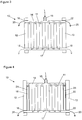
Figure 1 is a schematic side view of a fuel cell stack with a coolant feed inlet manifold and discharge outlet (not according to the invention); -
Figure 2 is a schematic side view of an alternative fuel cell stack with a coolant feed inlet manifold and discharge outlet (not according to the invention); -
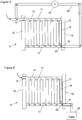
Figure 3 is a schematic side view of a fuel cell stack with a coolant feed inlet manifold and two discharge outlets; -
Figure 4 is schematic side view of an alternative fuel cell stack with a coolant feed inlet manifold and two discharge outlets; -
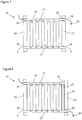
Figure 5 is a schematic view of the fuel cell stack offigure 2 coupled for recirculating coolant delivery to the coolant feed inlet manifold (not according to the invention); -
Figure 6 is a schematic view of the fuel cell stack offigure 2 coupled for passage of discharged coolant to a tank (not according to the invention); -
Figure 7 is a schematic view of the fuel cell stack offigure 1 comprising a variable flow controller (not according to the invention); and -
Figure 8 is a schematic view of the fuel cell stack offigure 2 comprising a variable flow controller (not according to the invention). - The various examples described below provide excess coolant injected into a coolant feed inlet manifold. The coolant may be water, preferably deionized water. A portion of the injected coolant passes to fluid coolant conduits in the fuel cells in the fuel cell stack. Another portion, described as the excess coolant, exits the coolant feed inlet manifold via a discharge conduit without passing through the fuel cells. By providing an excess of coolant to the coolant feed inlet manifold via the coolant inlet, the flow of coolant at an end of the manifold furthest from the inlet is sufficient to avoid or reduce problems arising due to very low coolant flow rates or stagnant coolant in the manifold.
- The examples described herein do not necessarily require the use of additional valve, pump and/or controllers in order to achieve the flow rates required to mitigate coolant stagnation problems. Thus the present invention advantageously provides improved fuel cell stack assemblies without the logistical considerations, extra engineering, maintenance considerations and increased cost of including additional components such as valves. However, the invention allows the incorporation of such valves if required for further control of the coolant fluid to/from the fuel cells.
- Further, embodiments described herein provide a solution to the problem of low coolant flow rates and coolant stagnation which can readily be combined with other design variations for fuel cell stacks, thereby contributing to a modular fuel cell system with flexibility for tailoring depending on the particular conditions required.
-
Figure 1 shows a schematic side view of afuel cell stack 10. Thestack 10 comprises a plurality offuel cells 11, each of which has an anode fluid flow path for delivering fuel to an anode surface of a membrane-electrode assembly and a cathode fluid flow path for delivering oxidant to a cathode surface of a membrane-electrode assembly. The fuel cells are held in a stack arrangement by way ofend plates feed inlet manifold 14, which extends down the length of thestack 10 between acoolant inlet 15 and adischarge conduit 16 at opposing ends of the coolantfeed inlet manifold 14. The coolantfeed inlet manifold 14 may be described as a coolant / water delivery manifold or gallery. - As indicated by the arrows in
figure 1 , coolant flows into the manifold from thecoolant inlet 15, then into each of the fluid flow paths of theseparate fuel cells 11. Preferably, the coolant combines with the fuel or oxidant flow at some point between the coolantfeed inlet manifold 14 and flow channels in theindividual fuel cells 11. These flow channels extend across the active surfaces of thefuel cells 11. The fuel and oxidant may be introduced into theindividual cells 11 using a separate fuel manifold and a separate oxidant manifold using known techniques. In some examples, unused fuel or oxidant may pass out of the fuel cells into anoutlet manifold 17 and, in some examples, from there to one or more exhaust ports /outlets outlet manifold 17 is not necessarily required for the anode fluid flow paths if all fuel is consumed at the active surfaces of thefuel cells 11, particularly if coolant injection is not provided on the anode sides of thefuel cells 11, although an anode exhaust line may be provided for periodic purging. In the examples described herein, anoutlet manifold 17 is shown coupled to each fluid coolant conduit of the plurality offuel cells 11 for discharge of at least coolant from eachfuel cell 11. - Also shown in
figure 1 is adischarge conduit 16 forexcess coolant 20 to pass out of the coolantfeed inlet manifold 14 without passing through the fluid coolant conduits of thefuel cells 11. Thedischarge conduit 16 offigure 1 may be described as an external coolant drain.Figure 1 thus shows a fuelcell stack assembly 10 comprising a plurality offuel cells 11 each having a fluid coolant conduit, and a coolantfeed inlet manifold 14 having acoolant inlet 15. The coolantfeed inlet manifold 14 is coupled to each fluid coolant conduit of thefuel cells 11 for distribution of coolant to each fuel cell. The coolantfeed inlet manifold 14 further comprises adischarge conduit 16 located at one end of the coolantfeed inlet manifold 14. Thedischarge conduit 16 is configured to dischargeexcess coolant 20 from the coolantfeed inlet manifold 14. - By locating the
discharge conduit 16 at the opposite end of the coolantfeed inlet manifold 14 to thecoolant inlet 15, excess coolant may be injected via thecoolant inlet 15 to thefuel cell stack 10 and the portion of the manifold furthest from thecoolant inlet 15 need not be subject to very low coolant flow rates. A coolant fluid flow may be provided at thecoolant inlet 15 to the coolantfeed inlet manifold 14 such that there is sufficient flow through the manifold, even at the end of thefuel cell stack 10 furthest from thecoolant inlet 14, to avoid or mitigate coolant fluid stagnation which can lead to problems as described earlier.Excess coolant 20, which does not pass through thefuel cells 11, exits the coolantfeed inlet manifold 14 by thedischarge conduit 16. -
Figure 2 shows a fuelcell stack assembly 10 comprising a plurality offuel cells 11 each having a fluid coolant conduit, and a coolantfeed inlet manifold 14 having acoolant inlet 15 at one end of the stack. The coolantfeed inlet manifold 14 comprises adischarge conduit 16 located at the other end of the stack, and thedischarge conduit 16 is configured to dischargeexcess coolant 20 from the coolantfeed inlet manifold 14. In this example, thedischarge conduit 16 passes from the end of the coolantfeed inlet manifold 14 opposite thecoolant inlet 15, across thefuel cell stack 10, parallel to the fuel cell conduits, to the side of the stack opposite to the coolant feelinlet manifold 14, before passing out through anoutlet manifold 17. In the examples described with respect tofigures 2 ,4 ,5, 6 and8 , thedischarge conduit 16 is shown to form part of theoutlet manifold 17, although this need not be the case and thedischarge conduit 16 may pass out from the fuel cell stack via a path separate from theoutlet manifold 17. - In some examples represented by
figure 2 , thedischarge conduit 16 may comprise or be formed within anadditional plate 21 extending across the width of the stack, parallel to the fuel cells, and disposed at the end of thefuel cell stack 10. Thisadditional plate 21 could be a heater plate or a current collector plate or an insulator plate adjacent to theend plate 13. Thedischarge conduit 16 infigure 2 may be described as an internal coolant drain. Thedischarge conduit 16 may be formed within theadditional plate 21 to allow the passage of excess coolant from the side of the fuel cell stack opposite thecoolant inlet 15. If thedischarge conduit 16 is included within a heater plate, thedischarge conduit 16 may preferably be located on the opposite side of the heater plate to the side incorporating heating elements. Providing thedischarge conduit 16 within a heater plate may provide an additional benefit in that, during cold start and operation, the heater plate may defrost any traces of ice in thedischarge conduit 16 allowing improved start up and operation. - The
discharge conduit 16 may comprise a conduit of predetermined reduced dimensions (compared to the dimensions of the manifold 14) to create a back pressure such that a coolant flow rate from the coolantfeed inlet manifold 14 into thedischarge conduit 16 is within a predetermined flow rate range. Thedischarge conduit 16 may be a length of pipework having particular dimensions relative to the coolantfeed inlet manifold 14 and may be at least partially serpentine or tortuous in form. The discharge conduit thereby presents a suitably increased impedance to coolant flow compared to the manifold and thereby achieves a desired flow rate and back pressure to the manifold. In this way, the flow parameters for coolant flow within thefuel cells 11 and excess coolant flow out from the coolantfeed inlet manifold 14 may be controlled. -
Figure 3 shows a fuelcell stack assembly 10 comprising a plurality offuel cells 11 each having a fluid coolant conduit, and a coolantfeed inlet manifold 14 having acoolant inlet 15 located towards the centre of the coolantfeed inlet manifold 14. The coolantfeed inlet manifold 14 comprises, in this embodiment, afirst discharge conduit 16 located at one end of the coolantfeed inlet manifold 14 and asecond discharge conduit 22 located at an opposite end of the coolantfeed inlet manifold 14. Thedischarge conduits feed inlet manifold 14. - Whereas the examples of
figures 1 and 2 show thecoolant inlet 15 located at one end of the coolantfeed inlet manifold 14, the example offigure 3 shows thecoolant inlet 15 located at the centre of the coolantfeed inlet manifold 14. The embodiment offigure 3 provides for an excess coolant flow into the coolantfeed inlet manifold 15 such that coolant can flow to each of the fuel cells in thestack 10, including those furthest from the coolant inlet 15 (those at the two ends of the fuel cell stack), with a sufficiently high flow so as to mitigate problems from stagnant coolant, or very low coolant flow rates in the manifold ends remote from thecoolant inlet 15. Theexcess coolant 20 which does not pass through the flow conduits of thefuel cells 11 exits the coolantfeed inlet manifold 14 by the twodischarge conduits Figure 3 also shows two exhaust ports /outlets outlet manifold 17. -
Figure 4 illustrates a fuelcell stack assembly 10 comprising a plurality offuel cells 11 each having a fluid coolant conduit, and a coolantfeed inlet manifold 14 having acoolant inlet 15 located towards the centre of the coolantfeed inlet manifold 14, similar tofigure 3 . The coolantfeed inlet manifold 14 comprises, in this embodiment, afirst discharge conduit 16 located at one end of the coolantfeed inlet manifold 14 and asecond discharge conduit 22 located at the opposite end of the coolantfeed inlet manifold 14. Both thefirst discharge conduit 16 and thesecond discharge conduit 22 comprise anadditional plate fuel cell stack 10. Theadditional plates respective end plate discharge conduits feed inlet manifold 14. - The embodiment of
figure 4 provides a similar advantage to that offigure 2 , in that if theadditional plates discharge conduits fuel cell stack 10 without adding complexity to thefuel cell stack 10. - If desired, a fuel cell stack may be formed having a
first discharge conduit 16 as shown infigure 3 exiting the coolant feelinlet manifold 14 directly, and asecond discharge conduit 22 comprised within anadditional plate 23 as shown infigure 4 . Theadditional plates coolant inlet 15 need not be in the centre of the coolant feel inlet manifold, and may be located part way along the manifold 14 if desired. -
Figure 5 illustrates thefuel cell stack 10 offigure 2 in which thedischarge conduit 16 includes arecirculation path 24 coupled to thecoolant inlet 15 for the recirculation of coolant to the plurality offuel cells 11. A pump, not shown, may be provided within therecirculation path 24. As shown infigure 5 , a coolant resistivity monitor 25 may be provided to determine the resistivity of coolant passing through therecirculation path 24. By recirculating the coolant fluid, there is less wastage of coolant fluid. By monitoring the resistivity of the coolant fluid, it may be determined when the coolant requires replacement or partial replacement. For example, a resistivity value below a particular value for deionised water may be used to control replacement of recirculating water or dilution of recirculating water. An exemplary minimum value could be, for example, 0.1 MOhm.cm. The location of the resistivity monitor 25 may be anywhere along the path of the recirculated coolant, and may therefore be located, for example, at thecoolant inlet 15, in therecirculation path 24, or in thedischarge conduit 16 internal to thefuel cell stack 10. More than one such resistivity monitor 25 may be used if desired, at different locations along the path of recirculated coolant. -
Figure 6 illustrates thefuel cell stack 10 offigure 2 in which thedischarge conduit 16 is coupled to an external coolant sump ortank 26. Thus excess coolant which is no longer required may be collected for storage, or for dilution and re-use in thefuel cell stack 10. The embodiments shown infigures 5 and 6 may be combined with the use of a valve and controller if desired. For example, coolant fluid may be recirculated until a predetermined value of resistivity of the coolant is reached. Upon reaching the predetermined value of resistivity, the controller may switch a valve to change the path of the excess coolant from being recirculated viarecirculation path 24 to being discharged to atank 26. -
Figures 7 and 8 show the examples offigures 1 and 2 respectively, further comprising aflow control assembly 27. Theflow control assembly 27 is coupled to thedischarge conduit 16 and is configured to control the back pressure of coolant fluid in the manifold 14 at thedischarge conduit 16, such that the pressure of coolant fluid at thedischarge conduit 16 can be held within a predetermined pressure range. Thedischarge conduit 16 may therefore comprise aflow control assembly 27 as a means for varying flow impedance and thereby back pressure to themanifold 14. - The
flow control assembly 27 may comprise, for example, one or more of a variable flow restrictor, an orifice plate, a needle valve, tubing of a predetermined length, and tubing of a predetermined width. For example, if the pressure at the end of the coolant feed inlet manifold, at the location of the flow control assemblies offigure 7 and 8 , is 1 bar, and 50 ml/min of coolant is to be injected via thecoolant inlet 15, then a 3 m length ofdischarge conduit 16 with a 1 mm diameter may be used between the outlet of the coolantfeed inlet manifold 14 and thecoolant inlet 15 to achieve this pressure. - The end of the
fuel cell stack 10 where thecoolant inlet 15 is located in the examples described with respect tofigures 1, 2 ,5, 6 ,7 and 8 may be selected as a negative polarity end of the fuel cell stack, and the opposite end of the fuel cell stack may be selected as a positive end. This could be reversed, if required.
Claims (13)
- A fuel cell stack assembly (10) comprising:a plurality of fuel cells (11) each having a fluid coolant conduit; anda coolant feed inlet manifold (14) having a coolant inlet (15);the coolant feed inlet manifold (14) coupled to each fluid coolant conduit for distribution of coolant to each fuel cell (11); andthe coolant feed inlet manifold (14) further comprising first and second discharge conduits (16, 22);wherein the first discharge conduit (16) is located at one end of the coolant feed inlet manifold, and the second discharge conduit (22) is located at an opposite end of the coolant feed inlet manifold (14), with the coolant inlet (15) in between; andwherein the discharge conduits (16, 22) are configured to discharge excess coolant from the coolant feed inlet manifold (14).
- The fuel cell stack assembly (10) of claim 1 wherein the coolant feed inlet (15) is located in the centre of the coolant feed inlet manifold (14).
- The fuel cell stack assembly (10) of claim 1 or claim 2, wherein one or each of the first and second discharge conduits (16, 22) comprises an additional plate (21, 23) extending across the stack and disposed at the one end of the fuel cell stack.
- The fuel cell stack assembly (10) of claim 3, wherein each additional plate (21, 23) comprises a heater plate, a current collector plate or an insulator plate.
- The fuel cell stack assembly (10) of any preceding claim, wherein the first discharge conduit (16) comprises a conduit of increased flow impedance compared to the coolant feed inlet manifold, such that a coolant flow rate from the coolant feed inlet manifold (14) to the first discharge conduit (16) is within a predetermined flow rate range.
- The fuel cell stack assembly (10) of any preceding claim in which the first discharge conduit (16) comprises a recirculation path (24) coupled to the coolant inlet (15) for the recirculation of coolant to the coolant feed inlet manifold (14).
- The fuel cell stack assembly (10) of claim 6, further comprising:
a coolant resistivity monitor (25) configured to determine the resistivity of coolant passing through the recirculation path. - The fuel cell stack assembly (10) of any preceding claim wherein the first discharge conduit (16) is coupled to an external coolant sump or tank (26).
- The fuel cell stack assembly (10) of any preceding claim further including a flow control assembly (27) coupled to the first discharge conduit (16) and configured to control the flow of coolant fluid from the coolant feed inlet manifold (14) to the first discharge conduit (16).
- The fuel cell stack assembly (10) of claim 9 in which the flow control assembly (27) comprises a variable flow restrictor.
- The fuel cell stack assembly (10) of any preceding claim in which the end of the fuel cell stack with the first discharge conduit (16) is an electrically positive end of the fuel cell stack.
- The fuel cell stack assembly (10) of any preceding claim, further comprising an outlet manifold (17) coupled to each fluid coolant conduit of the plurality of fuel cells for receiving coolant from each fuel cell.
- The fuel cell stack assembly of claim 12, wherein the first discharge conduit (16) forms part of the outlet manifold (17).
Applications Claiming Priority (2)
| Application Number | Priority Date | Filing Date | Title |
|---|---|---|---|
| GB1216637.7A GB2505958B (en) | 2012-09-18 | 2012-09-18 | Excess coolant fluid feed to fuel cell stacks |
| PCT/GB2013/052416 WO2014045019A1 (en) | 2012-09-18 | 2013-09-16 | Excess coolant fluid feed to fuel cell stacks |
Publications (2)
| Publication Number | Publication Date |
|---|---|
| EP2898563A1 EP2898563A1 (en) | 2015-07-29 |
| EP2898563B1 true EP2898563B1 (en) | 2019-11-06 |
Family
ID=47144441
Family Applications (1)
| Application Number | Title | Priority Date | Filing Date |
|---|---|---|---|
| EP13779328.7A Active EP2898563B1 (en) | 2012-09-18 | 2013-09-16 | Fuel cell stack |
Country Status (9)
| Country | Link |
|---|---|
| US (1) | US9450255B2 (en) |
| EP (1) | EP2898563B1 (en) |
| JP (1) | JP6328640B2 (en) |
| KR (1) | KR102217777B1 (en) |
| CN (1) | CN104704667B (en) |
| AR (1) | AR092614A1 (en) |
| GB (1) | GB2505958B (en) |
| TW (1) | TW201424111A (en) |
| WO (1) | WO2014045019A1 (en) |
Families Citing this family (7)
| Publication number | Priority date | Publication date | Assignee | Title |
|---|---|---|---|---|
| US10122040B2 (en) * | 2014-05-24 | 2018-11-06 | Daimler Ag | Reactant manifolds for fuel cell stacks operating below freezing |
| KR101734689B1 (en) * | 2015-10-15 | 2017-05-24 | 현대자동차주식회사 | cooling system of fuel cell Vehicle |
| KR102371046B1 (en) * | 2016-07-15 | 2022-03-07 | 현대자동차주식회사 | End cell heater for fuel cell |
| JP6995840B2 (en) | 2017-03-27 | 2022-01-17 | 住化積水フィルム株式会社 | Substrate for coating film surface protective film and coating film surface protective film using it |
| KR102634452B1 (en) * | 2018-09-04 | 2024-02-05 | 현대자동차주식회사 | Insulation resistance maintenance system and maintenance method of fuel cell |
| CN110911707A (en) * | 2019-10-22 | 2020-03-24 | 北京建筑大学 | Proton exchange membrane fuel cell system for vehicle in severe cold climate |
| JP2022154399A (en) * | 2021-03-30 | 2022-10-13 | 本田技研工業株式会社 | fuel cell system |
Family Cites Families (18)
| Publication number | Priority date | Publication date | Assignee | Title |
|---|---|---|---|---|
| US4706737A (en) * | 1986-11-20 | 1987-11-17 | International Fuel Cells Corporation | Fuel cell coolant inlet manifold and system |
| JP3349742B2 (en) * | 1993-01-28 | 2002-11-25 | マツダ株式会社 | Fuel cell vehicle |
| JPH08111231A (en) * | 1994-10-12 | 1996-04-30 | Kansai Electric Power Co Inc:The | Solid high polymer electrolyte type fuel cell |
| JPH0992317A (en) * | 1995-09-22 | 1997-04-04 | Fuji Electric Co Ltd | Fuel cell power generating device |
| JP4178849B2 (en) * | 2001-08-10 | 2008-11-12 | 株式会社デンソー | Fuel cell system |
| US6838201B2 (en) * | 2002-04-11 | 2005-01-04 | General Motors Corporation | Fuel cell stack coolant conductivity monitoring circuit |
| JP2004247258A (en) * | 2003-02-17 | 2004-09-02 | Sanyo Electric Co Ltd | Fuel cell laminated body, separator used therefor, and fuel cell system |
| EP1473791A1 (en) * | 2003-05-02 | 2004-11-03 | Matsushita Electric Industrial Co., Ltd. | Fuel cell power generator |
| JP2005235489A (en) * | 2004-02-18 | 2005-09-02 | Nissan Motor Co Ltd | Fuel cell system |
| US20050221149A1 (en) * | 2004-03-30 | 2005-10-06 | Sanyo Electric Co., Ltd. | Fuel cell stack |
| JP4780283B2 (en) * | 2005-05-30 | 2011-09-28 | トヨタ自動車株式会社 | Fuel cell |
| JP5034675B2 (en) * | 2007-05-22 | 2012-09-26 | トヨタ自動車株式会社 | Moving body |
| DE102007037853A1 (en) * | 2007-08-10 | 2008-07-31 | Daimler Ag | Fuel cell arrangement for use in motor vehicle, has coolant pipes which are provided between component and fuel cell stack, where coolant is supplied to side of stack from coolant port and coolant is re-conductable from component to stack |
| JP5231055B2 (en) * | 2008-03-17 | 2013-07-10 | 本田技研工業株式会社 | Fuel cell stack |
| US7923162B2 (en) * | 2008-03-19 | 2011-04-12 | Dana Canada Corporation | Fuel cell assemblies with integrated reactant-conditioning heat exchangers |
| US8617756B2 (en) * | 2009-09-02 | 2013-12-31 | Honda Motor Co., Ltd. | Fuel cell stack |
| DE112009005443B8 (en) * | 2009-12-16 | 2014-10-30 | Toyota Jidosha Kabushiki Kaisha | The fuel cell system |
| JP5765518B2 (en) * | 2010-07-27 | 2015-08-19 | 日産自動車株式会社 | Fuel cell system |
-
2012
- 2012-09-18 GB GB1216637.7A patent/GB2505958B/en active Active
-
2013
- 2013-09-11 TW TW102132747A patent/TW201424111A/en unknown
- 2013-09-16 KR KR1020157007413A patent/KR102217777B1/en active IP Right Grant
- 2013-09-16 US US14/428,953 patent/US9450255B2/en active Active
- 2013-09-16 EP EP13779328.7A patent/EP2898563B1/en active Active
- 2013-09-16 JP JP2015531643A patent/JP6328640B2/en active Active
- 2013-09-16 WO PCT/GB2013/052416 patent/WO2014045019A1/en active Application Filing
- 2013-09-16 CN CN201380048283.0A patent/CN104704667B/en active Active
- 2013-09-18 AR ARP130103348A patent/AR092614A1/en unknown
Non-Patent Citations (1)
| Title |
|---|
| None * |
Also Published As
| Publication number | Publication date |
|---|---|
| WO2014045019A1 (en) | 2014-03-27 |
| EP2898563A1 (en) | 2015-07-29 |
| CN104704667B (en) | 2017-03-15 |
| GB2505958B (en) | 2020-12-30 |
| GB201216637D0 (en) | 2012-10-31 |
| KR102217777B1 (en) | 2021-02-18 |
| CN104704667A (en) | 2015-06-10 |
| TW201424111A (en) | 2014-06-16 |
| JP2015531980A (en) | 2015-11-05 |
| US9450255B2 (en) | 2016-09-20 |
| US20150255810A1 (en) | 2015-09-10 |
| KR20150058244A (en) | 2015-05-28 |
| JP6328640B2 (en) | 2018-05-23 |
| AR092614A1 (en) | 2015-04-29 |
| GB2505958A (en) | 2014-03-19 |
Similar Documents
| Publication | Publication Date | Title |
|---|---|---|
| EP2898563B1 (en) | Fuel cell stack | |
| US5965288A (en) | Gas humidifying device for use with a fuel cell | |
| EP2898559B1 (en) | Coolant fluid feed to fuel cell stacks | |
| KR20140039195A (en) | Fuel cell, the overall size of which is reduced | |
| US20170324101A1 (en) | Proactive anode flooding remediation | |
| US10347927B2 (en) | Assembly for thermal management of a fuel cell | |
| US20130078543A1 (en) | Operation method for fuel cell, and fuel cell system | |
| US10158141B2 (en) | Fuel cell system including multiple fuel cell stacks | |
| US11695148B2 (en) | Fuel cell system | |
| JP2013101949A (en) | Fuel cell power generation system operating method | |
| JP2006228434A (en) | Fuel cell power generation system | |
| US20140170512A1 (en) | Method for mitigating recoverable voltage loss through humidification control | |
| CN219066856U (en) | Fuel cell system | |
| CN103875105A (en) | Separator plate with intermediate injection of gas, fuel cell, method of feeding a fuel cell | |
| KR102098622B1 (en) | Fuel cell system with the flow control | |
| KR20100022362A (en) | A fuel cell with insulated manifold | |
| KR20090095194A (en) | Hydrogenre circulation device for fuel cell system | |
| US20050252281A1 (en) | System and method for treating process fluids delivered to an electrochemical cell stack | |
| KR20120009842A (en) | Humidifier apparatus for fuel cell |
Legal Events
| Date | Code | Title | Description |
|---|---|---|---|
| PUAI | Public reference made under article 153(3) epc to a published international application that has entered the european phase |
Free format text: ORIGINAL CODE: 0009012 |
|
| 17P | Request for examination filed |
Effective date: 20150415 |
|
| AK | Designated contracting states |
Kind code of ref document: A1 Designated state(s): AL AT BE BG CH CY CZ DE DK EE ES FI FR GB GR HR HU IE IS IT LI LT LU LV MC MK MT NL NO PL PT RO RS SE SI SK SM TR |
|
| AX | Request for extension of the european patent |
Extension state: BA ME |
|
| DAX | Request for extension of the european patent (deleted) | ||
| 17Q | First examination report despatched |
Effective date: 20160502 |
|
| STAA | Information on the status of an ep patent application or granted ep patent |
Free format text: STATUS: EXAMINATION IS IN PROGRESS |
|
| GRAP | Despatch of communication of intention to grant a patent |
Free format text: ORIGINAL CODE: EPIDOSNIGR1 |
|
| STAA | Information on the status of an ep patent application or granted ep patent |
Free format text: STATUS: GRANT OF PATENT IS INTENDED |
|
| INTG | Intention to grant announced |
Effective date: 20190502 |
|
| GRAS | Grant fee paid |
Free format text: ORIGINAL CODE: EPIDOSNIGR3 |
|
| GRAA | (expected) grant |
Free format text: ORIGINAL CODE: 0009210 |
|
| STAA | Information on the status of an ep patent application or granted ep patent |
Free format text: STATUS: THE PATENT HAS BEEN GRANTED |
|
| AK | Designated contracting states |
Kind code of ref document: B1 Designated state(s): AL AT BE BG CH CY CZ DE DK EE ES FI FR GB GR HR HU IE IS IT LI LT LU LV MC MK MT NL NO PL PT RO RS SE SI SK SM TR |
|
| REG | Reference to a national code |
Ref country code: GB Ref legal event code: FG4D |
|
| REG | Reference to a national code |
Ref country code: CH Ref legal event code: EP Ref country code: AT Ref legal event code: REF Ref document number: 1200048 Country of ref document: AT Kind code of ref document: T Effective date: 20191115 |
|
| REG | Reference to a national code |
Ref country code: IE Ref legal event code: FG4D |
|
| REG | Reference to a national code |
Ref country code: DE Ref legal event code: R096 Ref document number: 602013062588 Country of ref document: DE |
|
| REG | Reference to a national code |
Ref country code: NL Ref legal event code: MP Effective date: 20191106 |
|
| REG | Reference to a national code |
Ref country code: LT Ref legal event code: MG4D |
|
| PG25 | Lapsed in a contracting state [announced via postgrant information from national office to epo] |
Ref country code: GR Free format text: LAPSE BECAUSE OF FAILURE TO SUBMIT A TRANSLATION OF THE DESCRIPTION OR TO PAY THE FEE WITHIN THE PRESCRIBED TIME-LIMIT Effective date: 20200207 Ref country code: NO Free format text: LAPSE BECAUSE OF FAILURE TO SUBMIT A TRANSLATION OF THE DESCRIPTION OR TO PAY THE FEE WITHIN THE PRESCRIBED TIME-LIMIT Effective date: 20200206 Ref country code: FI Free format text: LAPSE BECAUSE OF FAILURE TO SUBMIT A TRANSLATION OF THE DESCRIPTION OR TO PAY THE FEE WITHIN THE PRESCRIBED TIME-LIMIT Effective date: 20191106 Ref country code: BG Free format text: LAPSE BECAUSE OF FAILURE TO SUBMIT A TRANSLATION OF THE DESCRIPTION OR TO PAY THE FEE WITHIN THE PRESCRIBED TIME-LIMIT Effective date: 20200206 Ref country code: SE Free format text: LAPSE BECAUSE OF FAILURE TO SUBMIT A TRANSLATION OF THE DESCRIPTION OR TO PAY THE FEE WITHIN THE PRESCRIBED TIME-LIMIT Effective date: 20191106 Ref country code: LV Free format text: LAPSE BECAUSE OF FAILURE TO SUBMIT A TRANSLATION OF THE DESCRIPTION OR TO PAY THE FEE WITHIN THE PRESCRIBED TIME-LIMIT Effective date: 20191106 Ref country code: PT Free format text: LAPSE BECAUSE OF FAILURE TO SUBMIT A TRANSLATION OF THE DESCRIPTION OR TO PAY THE FEE WITHIN THE PRESCRIBED TIME-LIMIT Effective date: 20200306 Ref country code: PL Free format text: LAPSE BECAUSE OF FAILURE TO SUBMIT A TRANSLATION OF THE DESCRIPTION OR TO PAY THE FEE WITHIN THE PRESCRIBED TIME-LIMIT Effective date: 20191106 Ref country code: LT Free format text: LAPSE BECAUSE OF FAILURE TO SUBMIT A TRANSLATION OF THE DESCRIPTION OR TO PAY THE FEE WITHIN THE PRESCRIBED TIME-LIMIT Effective date: 20191106 Ref country code: NL Free format text: LAPSE BECAUSE OF FAILURE TO SUBMIT A TRANSLATION OF THE DESCRIPTION OR TO PAY THE FEE WITHIN THE PRESCRIBED TIME-LIMIT Effective date: 20191106 |
|
| PG25 | Lapsed in a contracting state [announced via postgrant information from national office to epo] |
Ref country code: IS Free format text: LAPSE BECAUSE OF FAILURE TO SUBMIT A TRANSLATION OF THE DESCRIPTION OR TO PAY THE FEE WITHIN THE PRESCRIBED TIME-LIMIT Effective date: 20200306 Ref country code: HR Free format text: LAPSE BECAUSE OF FAILURE TO SUBMIT A TRANSLATION OF THE DESCRIPTION OR TO PAY THE FEE WITHIN THE PRESCRIBED TIME-LIMIT Effective date: 20191106 Ref country code: RS Free format text: LAPSE BECAUSE OF FAILURE TO SUBMIT A TRANSLATION OF THE DESCRIPTION OR TO PAY THE FEE WITHIN THE PRESCRIBED TIME-LIMIT Effective date: 20191106 |
|
| PG25 | Lapsed in a contracting state [announced via postgrant information from national office to epo] |
Ref country code: AL Free format text: LAPSE BECAUSE OF FAILURE TO SUBMIT A TRANSLATION OF THE DESCRIPTION OR TO PAY THE FEE WITHIN THE PRESCRIBED TIME-LIMIT Effective date: 20191106 |
|
| PG25 | Lapsed in a contracting state [announced via postgrant information from national office to epo] |
Ref country code: ES Free format text: LAPSE BECAUSE OF FAILURE TO SUBMIT A TRANSLATION OF THE DESCRIPTION OR TO PAY THE FEE WITHIN THE PRESCRIBED TIME-LIMIT Effective date: 20191106 Ref country code: DK Free format text: LAPSE BECAUSE OF FAILURE TO SUBMIT A TRANSLATION OF THE DESCRIPTION OR TO PAY THE FEE WITHIN THE PRESCRIBED TIME-LIMIT Effective date: 20191106 Ref country code: EE Free format text: LAPSE BECAUSE OF FAILURE TO SUBMIT A TRANSLATION OF THE DESCRIPTION OR TO PAY THE FEE WITHIN THE PRESCRIBED TIME-LIMIT Effective date: 20191106 Ref country code: CZ Free format text: LAPSE BECAUSE OF FAILURE TO SUBMIT A TRANSLATION OF THE DESCRIPTION OR TO PAY THE FEE WITHIN THE PRESCRIBED TIME-LIMIT Effective date: 20191106 Ref country code: RO Free format text: LAPSE BECAUSE OF FAILURE TO SUBMIT A TRANSLATION OF THE DESCRIPTION OR TO PAY THE FEE WITHIN THE PRESCRIBED TIME-LIMIT Effective date: 20191106 |
|
| REG | Reference to a national code |
Ref country code: DE Ref legal event code: R097 Ref document number: 602013062588 Country of ref document: DE |
|
| REG | Reference to a national code |
Ref country code: AT Ref legal event code: MK05 Ref document number: 1200048 Country of ref document: AT Kind code of ref document: T Effective date: 20191106 |
|
| PG25 | Lapsed in a contracting state [announced via postgrant information from national office to epo] |
Ref country code: SM Free format text: LAPSE BECAUSE OF FAILURE TO SUBMIT A TRANSLATION OF THE DESCRIPTION OR TO PAY THE FEE WITHIN THE PRESCRIBED TIME-LIMIT Effective date: 20191106 Ref country code: SK Free format text: LAPSE BECAUSE OF FAILURE TO SUBMIT A TRANSLATION OF THE DESCRIPTION OR TO PAY THE FEE WITHIN THE PRESCRIBED TIME-LIMIT Effective date: 20191106 |
|
| PLBE | No opposition filed within time limit |
Free format text: ORIGINAL CODE: 0009261 |
|
| STAA | Information on the status of an ep patent application or granted ep patent |
Free format text: STATUS: NO OPPOSITION FILED WITHIN TIME LIMIT |
|
| 26N | No opposition filed |
Effective date: 20200807 |
|
| PG25 | Lapsed in a contracting state [announced via postgrant information from national office to epo] |
Ref country code: AT Free format text: LAPSE BECAUSE OF FAILURE TO SUBMIT A TRANSLATION OF THE DESCRIPTION OR TO PAY THE FEE WITHIN THE PRESCRIBED TIME-LIMIT Effective date: 20191106 Ref country code: SI Free format text: LAPSE BECAUSE OF FAILURE TO SUBMIT A TRANSLATION OF THE DESCRIPTION OR TO PAY THE FEE WITHIN THE PRESCRIBED TIME-LIMIT Effective date: 20191106 |
|
| PG25 | Lapsed in a contracting state [announced via postgrant information from national office to epo] |
Ref country code: IT Free format text: LAPSE BECAUSE OF FAILURE TO SUBMIT A TRANSLATION OF THE DESCRIPTION OR TO PAY THE FEE WITHIN THE PRESCRIBED TIME-LIMIT Effective date: 20191106 |
|
| PG25 | Lapsed in a contracting state [announced via postgrant information from national office to epo] |
Ref country code: MC Free format text: LAPSE BECAUSE OF FAILURE TO SUBMIT A TRANSLATION OF THE DESCRIPTION OR TO PAY THE FEE WITHIN THE PRESCRIBED TIME-LIMIT Effective date: 20191106 |
|
| REG | Reference to a national code |
Ref country code: CH Ref legal event code: PL |
|
| REG | Reference to a national code |
Ref country code: BE Ref legal event code: MM Effective date: 20200930 |
|
| PG25 | Lapsed in a contracting state [announced via postgrant information from national office to epo] |
Ref country code: LU Free format text: LAPSE BECAUSE OF NON-PAYMENT OF DUE FEES Effective date: 20200916 |
|
| PG25 | Lapsed in a contracting state [announced via postgrant information from national office to epo] |
Ref country code: FR Free format text: LAPSE BECAUSE OF NON-PAYMENT OF DUE FEES Effective date: 20200930 |
|
| PG25 | Lapsed in a contracting state [announced via postgrant information from national office to epo] |
Ref country code: CH Free format text: LAPSE BECAUSE OF NON-PAYMENT OF DUE FEES Effective date: 20200930 Ref country code: BE Free format text: LAPSE BECAUSE OF NON-PAYMENT OF DUE FEES Effective date: 20200930 Ref country code: LI Free format text: LAPSE BECAUSE OF NON-PAYMENT OF DUE FEES Effective date: 20200930 Ref country code: IE Free format text: LAPSE BECAUSE OF NON-PAYMENT OF DUE FEES Effective date: 20200916 |
|
| PG25 | Lapsed in a contracting state [announced via postgrant information from national office to epo] |
Ref country code: TR Free format text: LAPSE BECAUSE OF FAILURE TO SUBMIT A TRANSLATION OF THE DESCRIPTION OR TO PAY THE FEE WITHIN THE PRESCRIBED TIME-LIMIT Effective date: 20191106 Ref country code: MT Free format text: LAPSE BECAUSE OF FAILURE TO SUBMIT A TRANSLATION OF THE DESCRIPTION OR TO PAY THE FEE WITHIN THE PRESCRIBED TIME-LIMIT Effective date: 20191106 Ref country code: CY Free format text: LAPSE BECAUSE OF FAILURE TO SUBMIT A TRANSLATION OF THE DESCRIPTION OR TO PAY THE FEE WITHIN THE PRESCRIBED TIME-LIMIT Effective date: 20191106 |
|
| PG25 | Lapsed in a contracting state [announced via postgrant information from national office to epo] |
Ref country code: MK Free format text: LAPSE BECAUSE OF FAILURE TO SUBMIT A TRANSLATION OF THE DESCRIPTION OR TO PAY THE FEE WITHIN THE PRESCRIBED TIME-LIMIT Effective date: 20191106 |
|
| PGFP | Annual fee paid to national office [announced via postgrant information from national office to epo] |
Ref country code: GB Payment date: 20230927 Year of fee payment: 11 |
|
| PGFP | Annual fee paid to national office [announced via postgrant information from national office to epo] |
Ref country code: DE Payment date: 20230927 Year of fee payment: 11 |