EP2898435B1 - System and method for flexible distributed massively parallel processing (mpp) - Google Patents
System and method for flexible distributed massively parallel processing (mpp) Download PDFInfo
- Publication number
- EP2898435B1 EP2898435B1 EP13847772.4A EP13847772A EP2898435B1 EP 2898435 B1 EP2898435 B1 EP 2898435B1 EP 13847772 A EP13847772 A EP 13847772A EP 2898435 B1 EP2898435 B1 EP 2898435B1
- Authority
- EP
- European Patent Office
- Prior art keywords
- database
- resource group
- machine
- partitions
- management
- Prior art date
- Legal status (The legal status is an assumption and is not a legal conclusion. Google has not performed a legal analysis and makes no representation as to the accuracy of the status listed.)
- Active
Links
Images





Classifications
-
- G—PHYSICS
- G06—COMPUTING OR CALCULATING; COUNTING
- G06F—ELECTRIC DIGITAL DATA PROCESSING
- G06F9/00—Arrangements for program control, e.g. control units
- G06F9/06—Arrangements for program control, e.g. control units using stored programs, i.e. using an internal store of processing equipment to receive or retain programs
- G06F9/46—Multiprogramming arrangements
- G06F9/50—Allocation of resources, e.g. of the central processing unit [CPU]
- G06F9/5061—Partitioning or combining of resources
-
- G—PHYSICS
- G06—COMPUTING OR CALCULATING; COUNTING
- G06F—ELECTRIC DIGITAL DATA PROCESSING
- G06F16/00—Information retrieval; Database structures therefor; File system structures therefor
- G06F16/20—Information retrieval; Database structures therefor; File system structures therefor of structured data, e.g. relational data
- G06F16/22—Indexing; Data structures therefor; Storage structures
-
- G—PHYSICS
- G06—COMPUTING OR CALCULATING; COUNTING
- G06F—ELECTRIC DIGITAL DATA PROCESSING
- G06F16/00—Information retrieval; Database structures therefor; File system structures therefor
- G06F16/20—Information retrieval; Database structures therefor; File system structures therefor of structured data, e.g. relational data
- G06F16/24—Querying
- G06F16/245—Query processing
- G06F16/2453—Query optimisation
- G06F16/24532—Query optimisation of parallel queries
-
- G—PHYSICS
- G06—COMPUTING OR CALCULATING; COUNTING
- G06F—ELECTRIC DIGITAL DATA PROCESSING
- G06F16/00—Information retrieval; Database structures therefor; File system structures therefor
- G06F16/20—Information retrieval; Database structures therefor; File system structures therefor of structured data, e.g. relational data
- G06F16/25—Integrating or interfacing systems involving database management systems
-
- G—PHYSICS
- G06—COMPUTING OR CALCULATING; COUNTING
- G06F—ELECTRIC DIGITAL DATA PROCESSING
- G06F2209/00—Indexing scheme relating to G06F9/00
- G06F2209/50—Indexing scheme relating to G06F9/50
- G06F2209/505—Clust
Definitions
- the present disclosure relates to a massively parallel processing (MPP) database management system and, in particular embodiments, to a management system able to detach the number of database partitions from the number of fixed processors.
- MPP massively parallel processing
- MPP massively parallel processing
- An MPP database system is based on shared-nothing architecture, with the tables of its databases partitioned into segments and distributed to different processing nodes. There is no data sharing among the processing nodes.
- database queries arrive, the work of each query is divided and assigned to one of the processing nodes according to a data distribution plan and an optimized execution plan.
- the processing entities in each processing node manage only their portion of the data. However, these processing entities may communicate with one another to exchange necessary information during their work execution.
- a query may be divided into multiple sub-queries, and the sub-queries may be executed in parallel or in some optimal order in some or all the processing nodes.
- the results of the sub-queries may be aggregated and further processed, and subsequently more sub-queries may the executed according to the results.
- a traditional MPP database system allows a database administrator to create a database and distribute its data (i.e., create database partitions) to a fixed number of processors that are setup ahead of time.
- the number of partitions a database administrator can create is fixed and directly corresponds to the number of processors available in the traditional MPP database system. In other words, the number of partitions and the number of processors is always the same. If additional partitions are desired, the entire process of setting up instances and partitions must be repeated.
- US 2011/0041006 A1 discusses a system and method for processing a distributed transaction for an application. Aspects of the system and method provide committal of distributed transaction independently of persistent storage which can make the speed advantages of data grid computing available for high volume distributed transactions, without losing the reliability of conventional database system.
- US 2012/0109888 A1 discusses a data partitioning method for a distributed parallel database system, comprising creating fact tables and dimension tables according to a constructed distributed parallel database system, inserting records of the dimension tables and the fact tables into the nodes according to the partitioning rules, replicating the records of dimension tables into the nodes that include fact tables, performing data deletion, and performing data update.
- US 7,120 , 690 B1 discusses a directory database distributed throughout a network in each of the nodes, the contents of the distributed database being maintained consistent or replicated throughout the network.
- a master node updates each directory database in each node of the network in its network or domain when the configuration changes.
- WO 2010/037794 A2 discusses data replication in different database nodes of a geographically distributed database wherein clients cannot always perform any database-related operation in the closest database node.
- Each node is arranged for storing a replica of at least a partition of data wherein one of the replicas is a master replica, and a master node is in charge of the master replica for updating the data in the distributed replicas.
- An embodiment method for massively parallel processing includes initiating, by a resource group manager, a management instance on an initial machine, the management instance generating an empty initial database partition corresponding to the initial machine, determining, by the management instance, a total number of database partitions desired for processing a database, the total number of database partitions including the initial database partition, determining, by a resource group manager, a number of additional machines available to process the database, wherein the total number of the database partitions is greater than a sum total number of the initial machine and the additional machines, grouping, by the resource group manager, the initial machine and the additional machines together in a resource group, wherein the resource group is expandable over time to add a new machine when a new machine become available to process the database, generating, by the resource group manager, a database partition-to-processing machine mapping chart in accordance with the total number of database partitions and the number of additional machines and keeping, by the resource group manager, the management instance on the initial machine as the management instance of the first database partition of the database and and creating, by the resource
- An embodiment massively parallel processing system including an initial machine and additional machines in a resource group, wherein the resource group has a flexible membership permitting a new machine for processing the database to be added, the initial machine running a management instance corresponding to an empty initial partition for processing a database, wherein the management instance on the initial machine is configured to determine a total number of database partitions desired for processing a database, the total number of database partitions including the initial database partition; a a resource group manager, configured to determine a number of additional machines available to process the database and to generate a database partition-to-processing machine mapping chart in accordance with the total number of database partitions and the number of machines in the resource group and to create management instances on the additional machines in the resource group to generate the total number of database partitions desired for the database and attach the storage space of the partitions to the database management instances according to the database partition-to-processing machine mapping chart,
- the management instance on the initial machine is kept as the management instance of the first database partition wherein an additional machine in the resource group is configured to run two of the management instances for processing the database, each of the management instances corresponding to an additional database partition; wherein the resource group manager is configured to expand the resource group to include a new machine; wherein the resource group manager is configured to alter the database partition-to-processing machine mapping chart in accordance with the total number of database partitions and the number of machines in the expanded resource group; wherein the resource group manager is configured to relocate one of the management instances from the additional machine running two of the management instances to the new machine.
- MPP massively parallel processing
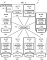
- a conventional or typical massively parallel processing (MPP) database system configuration 10 for on-line analytical processing (OLAP) is illustrated.
- a client application 100 presents queries 101 to a machine 110a having an active coordinator 120a.
- the machine 110a may be operating in conjunction with or alongside another machine 110b having a passive coordinator 110b.
- the machines 110a-110b are operably coupled to the interconnect 160.
- the interconnect 160 permits the machines 110a-110b to communicate with additional machines, namely machines 110c-110h.
- machines 110c, 110e, and 110g include an active database management instance 130a, 132a, and 134a, respectively.
- machines 110d, 110f, and 110h include a passive database management instance 130b, 132b, and 134b, respectively.
- Each of the machines 110c-110h is associated with one of the database partitions, namely partitions 140a-144b as shown in Figure 1 .
- the machine 110a communicating with the client application 100 and the adjacent machine 110b do not have an associated partition.
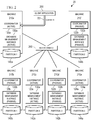
- a client application 200 presents queries 201 to a machine 210a having an active coordinator 120a and an active database (DB) management instance 130a.
- DB active database
- the machine 210a is operably coupled to the interconnect 260.
- the interconnect 260 permits the machine 210b to communicate with additional machines, namely machines 210b-210f.
- machines 210c and 210e include an active coordinator 122a, 124a and an active database management instance 132a, 134a, respectively.
- machines 210b, 210d, and 210f include a passive coordinator 120b, 122b, 124b and a passive database management instance 130b, 132b, 134b, respectively.
- Each of the machines 210a-210f is associated with one of the database partitions, namely partitions 140a-144b as shown in Figure 1 .
- the machine 210a communicating with the client application 200 has an associated partition 140a.
- a database creation scenario on a traditional massively parallel processing database system 30 is illustrated.
- a client 300 is operably coupled to the interconnect 320.
- the interconnect 320 is operably coupled to machines 310a, 310b, 310c.
- Each of the machines 310a, 310b, 310c includes an active database management instance 330, 332, 334 associated with an empty partition 340, 342, 344, respectively.
- Each of the database management instances 330, 332, 334 and the empty partitions 340, 342, 344 in Figure 3 are created simultaneously. Moreover, as shown in Figure 3 , only one partition is permitted per available machine. If there is a desire to add a new partition or to remove an existing partition in the traditional massively parallel processing database system 30 of Figure 3 , the entire database creation scenario must be performed all over again. As such, the desire to re-partition a database is cumbersome and time consuming for an information technology (IT) administrator and/or a database administrator (DBA).
- IT information technology
- DBA database administrator
- an embodiment MPP database system 40 during an initial setup and formation of a pod 401 (a.k.a., cluster, resource group, etc.).
- a client application 400 presents queries to an interconnect 420.
- the interconnect 420 passes the queried to a machine 410a.
- a database management instance 430a is initiated on an initial machine 410a.
- the database management instances disclosed herein are running or executing on a processor associated the machine. As shown, the database management instance 430a generates an initial partition 450 corresponding to the initial machine 410a. Notably, the initial partition 450 is empty of any data or information.
- a total number of partitions desired for processing a database is determined.
- the total number of partitions includes the initial partition 450. Such determination may be based, at least in part, upon the query or instructions received from the client 400.
- a number of additional machines 410b, 410c available to process the database is determined.
- the term machine may refer to and/or incorporate a variety of resources including, for example, a processor, memory, storage node, or other infrastructure. Indeed, the term machine is not meant to be limiting. Also, while two of the additional machines 410b, 410c are illustrated in Figure 4a , it should be appreciated that more of fewer of the additional machines may be available.
- the initial machine 410a and the additional machines 410b, 410c are grouped together in the pod 401.
- the machine 410d associated with the pod administrator 400 is not considered to be an available resource for processing the database and, as such, not included within the pod 401.
- the management instance 430a is launched on the additional machines 410b, 410c in the pod 401. As shown in Figure 4b , this generates the total number of partitions 450, 452, 454 desired for the database.
- the machines 410a, 410b, 410c includes a pod manager 440a, 440b, 440c, respectively.
- the pod managers 440a, 440b, 440c may be used to facilitate communications and cooperation between the machines 410a, 410b, 410c relative to the partitions 450, 452, 454 in the processing of the database.
- the client 500 may request, by way of the interconnect 520, for a number of partitions that differs from the number of machines available.
- a client request would be denied.
- the embodiment management systems disclosed herein are able to accommodate such a request, as more fully explained below.
- the management instance 530a is initiated on the initial machine 510a as shown in Figure 5a . As shown, the management instance 530a generates an initial partition 550 corresponding to the initial machine 510a. Thereafter, the total number of partitions desired for processing the database is determined based on the client 500 request. Notably, the total number of partitions includes the initial partition 550. In the example depicted in Figure 5a , the number of partitions (e.g., four) requested by the client exceeds the number of machines available (e.g., three).
- a number of additional machines 510b, 510c available to process the database is determined. As shown in Figure 5a , a sum total of the additional machines 510b, 510c and the initial machine 510a (i.e., three) is less than the total number of partitions 550-556 desired (i.e., four). Thereafter, the initial machine 510a and the additional machines 510b, 510c are grouped together in the pod 501. Then, the management instance 530b, 530c, 540d on the additional machines 510b, 510c in the pod 501 is launched to generate the total number of partitions desired for the database.
- machine 510c supports two of the management instances 530c, 540d and two of the partitions 554, 556.
- the machine 510d associated with the pod administrator 500 is not considered to be an available resource for processing the database and, as such, not included within the pod 501.
- the pod 501 when a new machine 510e becomes available, the pod 501 is expanded to include that new machine.
- the management instance 530c and the partition 556 from machine 510c in Figure 5a are relocated to the new machine 510e as shown in Figure 5b .
- This process of adding new machines (i.e., resources) to the pod 501 may be repeated as the new machines become available.
- the pod 501 has a flexible membership and is expandable or contractible over time.
- the new machine 510e may be added to the pod 501 even after the management instances 530b, 530c, 530d were launched on the additional machines 510b, 510c in Figure 5a .
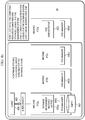
- FIG. 6 a high-level flow diagram illustrating an embodiment preparation and creation of the database by an information technology (IT) administrator and a database administrator (DBA) is provided.
- IT information technology
- DBA database administrator
- the IT administrator prepares for pod management.
- the DBA creates the pods for the database.
- the DBA creates a database, tables, and the partitions.
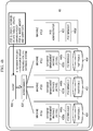
- a flow diagram illustrating an embodiment creation of the pod 401, 501 by a pod manager is provided.
- the pod manager begins the process of creating the pod.
- an input of pod resources i.e., parameters
- these resources or parameters may include, for example, a compute node, storage, and so on.
- the pod manager validates that the user has authority to create the pod. The pod manager also validates that the user has permission to create the pod directory, and so on.
- the pod manager saves the pod configuration with the pod administrator.
- the pod manager allocates a storage volume or space.
- the pod manager also creates and starts one database management instance on one of the nodes (i.e., machines) in the pod.
- the pod manager further attaches the storage volume to the instance.
- the database management instance e.g., the database management instance 430 in Figure 4a
- the process ends.
- FIG. 8 a flow diagram illustrating a database (DB) management instance handling the creation of a database and its partition is provided.
- DB database
- MPP massively parallel processing
- a create database command is received by a database management instance (e.g., the database management instance 430 in Figure 4a ).
- the create database management instruction is handled by the database management instance, which validates input parameters, creates a database structure into its storage (e.g., the empty partition 450 in Figure 4a ), and saves the database metadata into a catalog in the storage.
- the database management instance receives commands such as create schema, create table, or create database partition commands.
- commands such as create schema, create table, or create database partition commands.
- a determination of which command is received is made by the database management instance. If the create schema command 842 was received, then in block 850 the database management instance creates schema management information under the associated database structure and saves the schema metadata into a catalog in the storage (e.g., the partition 450). If the create table command 844 was received, then in block 860 the database management instance creates a table structure under the associated database and schema and saves the table metadata into a catalog in the storage (e.g., the partition 450).
- the database management instance notes the number of partitions (N) that the user decided upon, selects a data distribution algorithm, creates a database partition structure and metadata, partitions tables accordingly to fit into the database partitions, and saves the database partitioning metadata into a catalog in the storage.
- the database management instance also calls the pod manager (e.g., pod manager 440a in Figure 4a ) to create the database management instances on the additional machines or resources (e.g., machines 410b, 410c in Figure 4b , machines 510b, 510c, 510e in Figures 5a-5b ). Thereafter, in block 880, the process ends.
- the pod manager e.g., pod manager 440a in Figure 4a
- the pod manager begins by forming a flexible pod (i.e., cluster, resource group) and by creating MPP database partitions.
- the pod manager created a partition-processor map by computing a number of partition(s) per processing node and generating a partition-to-processing node mapping chart.
- the mapping ensures that the workload is balanced on the available nodes.
- the mapping may have the configuration of Figure 4b (one partition per processing node) or the configuration of Figure 5a (one or more partitions per processing node).
- an active-to-passive-processing-node mapping chart may be created for each partition.
- the pod manager creates the database management instances.
- the pod manager keeps the original database management instance (e.g., management instance 430a in Figure 4a ) as the instance for the first partition (Partition 1).
- the pod manager creates, configures, and launches an active database management instance (instances 430b, 430c, and so on) for each of the processing nodes.
- the pod manager allocates a storage space (partition 452, partition 454, etc.).
- the storage is attached to the database management instance at the processing node.
- the instance will create a catalog on the storage space (e.g., 430b-452, 430c-454, etc.).
- the pod manager saves the mapping information. In doing so, the pod manager saves the partition-to-processing-node map in the catalog of each storage volume/space. The pod manager also saves the active-to-passive-processing-node map into the catalog. In an embodiment, the information is entered into the catalog through one of the database management instances and the instances synchronize all the catalogs. Thereafter, in block 940, the process ends.
- a pod manager e.g., pod manager 540a, 540b, 540c in Figures 5a-5b
- the pod manager receives information about the new node(s) (i.e., machines, resources) to be added or removed.
- the pod manager alters the partition-processor map.
- the pod manager computes the number of partition(s) per processing node and alters the partition-to-processing-node mapping chart.
- the new mapping ensures that the workload is balanced on the available nodes. For example, an original mapping may resemble the configuration in Figure 5a and a new mapping may resemble the configuration in Figure 5b .
- the active-to-passive-processing-node mapping chart is altered for each partition.
- the pod manager relocates database partitions among processing nodes. If adding nodes, then for each node, the pod manager creates, configures, and launches an active database management instance. The pod manager also moves identified database partitions to their newly designated node by un-mounting a storage space from its current processing node to the new processing node (e.g., 556 from 510c to 510e in Figures 5a-5b ). If the storage space is a direct attached storage, the pod manager copies the data to the new designated node. The pod manager also attaches the storage space to the database management instance in the new processing node.
- the pod manager saves the mapping information. In doing so, the pod manager saves the updated partition-to-processing-node map on each of the database management instance catalogs.
- the database manager also saves the active-to-passive-processing-node map into the catalog.
- the information is entered into a catalog of one of the database management instances and the instances synchronize their catalog. Thereafter, in block 1050, the process ends.
- the table 50 includes such information as, for example, a pod name, pod users and securing information, the pod network information, the database management instance access information, a list of processing machines/nodes, a list of storage spaces/volumes and their size, cluster, configuration, and system management and monitoring information.
- other information may be included in the table 50.
- some of the information may be removed from the table depicted in Figure 11 .
- the table 60 includes such information as, for example, the database structure and metadata, the schema/database structure and metadata, the table/schema/database structure and metadata, the database partition structure and metadata, the number of partitions (N), the active partition-to-processing-node map, and the active-to-passive-processing-node map.
- other information may be included in the table 60.
- some of the information may be removed from the table depicted in Figure 12 .
- an MPP database system is first assigned a pool of resources - machines / processors, storage, and possibly also memory that the MPP database system is allowed to access/use. These resources, the processors, storage, and their communication channels do not have to form a pod/cluster (collaborative group) initially.
- the required computing resources are then grabbed from the allocated pool on-demand and managed as a cluster, the necessary number of database management instances is then launched, and the database partitions (each of the data store) are then physically created on the instances.
- the number of database partitions created does not have to directly correspond to or match the actual number of machines (processors). For example, if there are only 5 machines (processors) available, a database administrator can still create 10 database partitions by permitting two partitions to be served by one machine (one processor). When more machines become available, the partitions can be relocated to the available processor at a later time.
Landscapes
- Engineering & Computer Science (AREA)
- Theoretical Computer Science (AREA)
- Physics & Mathematics (AREA)
- General Engineering & Computer Science (AREA)
- General Physics & Mathematics (AREA)
- Databases & Information Systems (AREA)
- Software Systems (AREA)
- Data Mining & Analysis (AREA)
- Computational Linguistics (AREA)
- Information Retrieval, Db Structures And Fs Structures Therefor (AREA)
- Multi Processors (AREA)
Description
- The present application relates to
U.S. Patent Application Serial No. 13/653,308 filed October 16, 2012 by Yuan Dai et al - The present disclosure relates to a massively parallel processing (MPP) database management system and, in particular embodiments, to a management system able to detach the number of database partitions from the number of fixed processors.
- The concept of massively parallel processing (MPP) is the coordinated processing of a program by multiple processors, with each processer working on different parts of the program. The processors communicate with one another to complete a task with each of them using its own operating system and memory resources.
- An MPP database system is based on shared-nothing architecture, with the tables of its databases partitioned into segments and distributed to different processing nodes. There is no data sharing among the processing nodes. When database queries arrive, the work of each query is divided and assigned to one of the processing nodes according to a data distribution plan and an optimized execution plan. The processing entities in each processing node manage only their portion of the data. However, these processing entities may communicate with one another to exchange necessary information during their work execution. A query may be divided into multiple sub-queries, and the sub-queries may be executed in parallel or in some optimal order in some or all the processing nodes. The results of the sub-queries may be aggregated and further processed, and subsequently more sub-queries may the executed according to the results.
- One of the challenges in an MPP database system has always been in setting up the distributed system, which includes configuring the machines, creating the database, partitioning the tables, and distributing the segments. How data is distributed and how much the distribution is aligned with the business logic greatly determines the overall performance of the system.
- A traditional MPP database system allows a database administrator to create a database and distribute its data (i.e., create database partitions) to a fixed number of processors that are setup ahead of time. Unfortunately, the number of partitions a database administrator can create is fixed and directly corresponds to the number of processors available in the traditional MPP database system. In other words, the number of partitions and the number of processors is always the same. If additional partitions are desired, the entire process of setting up instances and partitions must be repeated.
US 2011/0041006 A1 discusses a system and method for processing a distributed transaction for an application. Aspects of the system and method provide committal of distributed transaction independently of persistent storage which can make the speed advantages of data grid computing available for high volume distributed transactions, without losing the reliability of conventional database system.
US 2012/0109888 A1 discusses a data partitioning method for a distributed parallel database system, comprising creating fact tables and dimension tables according to a constructed distributed parallel database system, inserting records of the dimension tables and the fact tables into the nodes according to the partitioning rules, replicating the records of dimension tables into the nodes that include fact tables, performing data deletion, and performing data update.
US 7,120 ,690 B1 discusses a directory database distributed throughout a network in each of the nodes, the contents of the distributed database being maintained consistent or replicated throughout the network. A master node updates each directory database in each node of the network in its network or domain when the configuration changes.
WO 2010/037794 A2 discusses data replication in different database nodes of a geographically distributed database wherein clients cannot always perform any database-related operation in the closest database node. Each node is arranged for storing a replica of at least a partition of data wherein one of the replicas is a master replica, and a master node is in charge of the master replica for updating the data in the distributed replicas. - The embodiments of the present invention are defined in the claims. Any other reference to an embodiment is considered merely as a further example.
- An embodiment method for massively parallel processing includes initiating, by a resource group manager, a management instance on an initial machine, the management instance generating an empty initial database partition corresponding to the initial machine, determining, by the management instance, a total number of database partitions desired for processing a database, the total number of database partitions including the initial database partition, determining, by a resource group manager, a number of additional machines available to process the database, wherein the total number of the database partitions is greater than a sum total number of the initial machine and the additional machines, grouping, by the resource group manager, the initial machine and the additional machines together in a resource group, wherein the resource group is expandable over time to add a new machine when a new machine become available to process the database, generating, by the resource group manager, a database partition-to-processing machine mapping chart in accordance with the total number of database partitions and the number of additional machines and keeping, by the resource group manager, the management instance on the initial machine as the management instance of the first database partition of the database and and creating, by the resource group manager management instance on the additional machines in the resource group to generate the total number of database partitions desired for the database and attach the storage space of the partitions to the database management instances according to the database partition-to-processing machine mapping chart, wherein one of the additional machines in the resource group is running at least two of the management instances for processing the database; expanding, by the resource group manager the resource group to include a new machine; altering, by the resource group manager, the database partition-to-processing machine mapping chart in accordance with the total number of database partitions and the number of machines in the expanded resource group; relocating, by the resource group manager, one of the management instances from the additional machine running two of the management instances to the new machine.
- An embodiment massively parallel processing system including an initial machine and additional machines in a resource group, wherein the resource group has a flexible membership permitting a new machine for processing the database to be added, the initial machine running a management instance corresponding to an empty initial partition for processing a database, wherein the management instance on the initial machine is configured to determine a total number of database partitions desired for processing a database, the total number of database partitions including the initial database partition; a a resource group manager, configured to determine a number of additional machines available to process the database and to generate a database partition-to-processing machine mapping chart in accordance with the total number of database partitions and the number of machines in the resource group and to create management instances on the additional machines in the resource group to generate the total number of database partitions desired for the database and attach the storage space of the partitions to the database management instances according to the database partition-to-processing machine mapping chart,
- wherein the management instance on the initial machine is kept as the management instance of the first database partition wherein an additional machine in the resource group is configured to run two of the management instances for processing the database, each of the management instances corresponding to an additional database partition; wherein the resource group manager is configured to expand the resource group to include a new machine; wherein the resource group manager is configured to alter the database partition-to-processing machine mapping chart in accordance with the total number of database partitions and the number of machines in the expanded resource group; wherein the resource group manager is configured to relocate one of the management instances from the additional machine running two of the management instances to the new machine.
- For a more complete understanding of the present disclosure, and the advantages thereof, reference is now made to the following descriptions taken in conjunction with the accompanying drawing, in which:
-
Figure 1 illustrates a massively parallel processing (MPP) database system configuration for on-line analytical processing (OLAP); -
Figure 2 illustrates an MPP database system configuration for on-line transactional processing (OLTP); -
Figure 3 illustrates a database creation scenario on a traditional MPP database system; -
Figure 4a illustrates an embodiment MPP database system during an initial setup and formation of a pod; -
Figure 4b shows the embodiment MPP database system ofFigure 4a when a database is created and a partitioning policy is defined for the machines in the pod; -
Figure 5a illustrates an embodiment MPP database system when a number of database partitions is greater than the a number of available machines in the pod; -
Figure 5b illustrates the embodiment MPP database system ofFigure 5a when a new machine is added to the pod; -
Figure 6 is a high-level flow diagram illustrating preparation and creation of the database by an information technology (IT) administrator and a database administrator (DBA); -
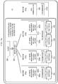
Figure 7 is a flow diagram illustrating creation of the pod by a pod manager; -
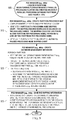
Figure 8 is a flow diagram illustrating a database (DB) management instance handling the creation of a database and its partition; -
Figure 9 is a flow diagram illustrating a pod manager forming a flexible pod and creating the database partitions; -
Figure 10 is a flow diagram illustrating relocation of a database partition when a new machine is added or an existing machine is removed from the pod; -
Figure 11 is a table illustrating example pod configurations; and -
Figure 12 is a table illustrating an example database catalog. - Corresponding numerals and symbols in the different figures generally refer to corresponding parts unless otherwise indicated. The figures are drawn to clearly illustrate the relevant aspects of the embodiments and are not necessarily drawn to scale.
- The making and using of the presently preferred embodiments are discussed in detail below. It should be appreciated, however, that the present disclosure provides many applicable inventive concepts that can be embodied in a wide variety of specific contexts. The specific embodiments discussed are merely illustrative and do not limit the scope of the disclosure.
- The present disclosure will be described with respect to preferred embodiments in a specific context, namely a massively parallel processing (MPP) database and management thereof. The concepts in the disclosure may also apply, however, to other types of databases and data management systems.
- Referring now to
Figure 1 , and for the purpose of reference, a conventional or typical massively parallel processing (MPP)database system configuration 10 for on-line analytical processing (OLAP) is illustrated. As shown, aclient application 100 presentsqueries 101 to amachine 110a having anactive coordinator 120a. Themachine 110a may be operating in conjunction with or alongside another machine 110b having a passive coordinator 110b. - Still referring to
Figure 1 , themachines 110a-110b are operably coupled to theinterconnect 160. As the name implies, theinterconnect 160 permits themachines 110a-110b to communicate with additional machines, namelymachines 110c-110h. Notably,machines database management instance machines database management instance machines 110c-110h is associated with one of the database partitions, namelypartitions 140a-144b as shown inFigure 1 . In thesystem configuration 10 ofFigure 1 , themachine 110a communicating with theclient application 100 and the adjacent machine 110b do not have an associated partition. - Referring now to
Figure 2 , and for the purpose of reference, a conventional or typical MPPdatabase system configuration 20 for on-line transactional processing (OLTP) is illustrated. As shown, aclient application 200 presentsqueries 201 to amachine 210a having anactive coordinator 120a and an active database (DB)management instance 130a. - Still referring to
Figure 2 , themachine 210a is operably coupled to theinterconnect 260. As the name implies, theinterconnect 260 permits themachine 210b to communicate with additional machines, namelymachines 210b-210f. Notably,machines active coordinator database management instance machines passive coordinator database management instance machines 210a-210f is associated with one of the database partitions, namelypartitions 140a-144b as shown inFigure 1 . In thesystem configuration 20 ofFigure 2 , themachine 210a communicating with theclient application 200 has an associatedpartition 140a. - Referring now to
Figure 3 , a database creation scenario on a traditional massively parallelprocessing database system 30 is illustrated. As shown inFigure 3 , aclient 300 is operably coupled to theinterconnect 320. In turn, theinterconnect 320 is operably coupled tomachines machines database management instance empty partition - Each of the
database management instances empty partitions Figure 3 are created simultaneously. Moreover, as shown inFigure 3 , only one partition is permitted per available machine. If there is a desire to add a new partition or to remove an existing partition in the traditional massively parallelprocessing database system 30 ofFigure 3 , the entire database creation scenario must be performed all over again. As such, the desire to re-partition a database is cumbersome and time consuming for an information technology (IT) administrator and/or a database administrator (DBA). - Referring now to
Figure 4a , an embodimentMPP database system 40 during an initial setup and formation of a pod 401 (a.k.a., cluster, resource group, etc.). As shown, aclient application 400 presents queries to aninterconnect 420. Theinterconnect 420 passes the queried to amachine 410a. Thereafter, adatabase management instance 430a is initiated on aninitial machine 410a. - In an embodiment, the database management instances disclosed herein are running or executing on a processor associated the machine. As shown, the
database management instance 430a generates aninitial partition 450 corresponding to theinitial machine 410a. Notably, theinitial partition 450 is empty of any data or information. - After the
database management instance 430a and theinitial partition 450 have been created, a total number of partitions desired for processing a database is determined. The total number of partitions includes theinitial partition 450. Such determination may be based, at least in part, upon the query or instructions received from theclient 400. - Once the total number of partitions has been determined, a number of
additional machines additional machines Figure 4a , it should be appreciated that more of fewer of the additional machines may be available. - After the number of additional machines (i.e., resources) has been determined, the
initial machine 410a and theadditional machines pod 401. Notably, themachine 410d associated with thepod administrator 400 is not considered to be an available resource for processing the database and, as such, not included within thepod 401. - Referring collectively to
Figures 4a-4b , after thepod 401 has been defined themanagement instance 430a is launched on theadditional machines pod 401. As shown inFigure 4b , this generates the total number ofpartitions machines pod manager pod managers machines partitions - Referring now to
Figure 5 , in an embodiment theclient 500 may request, by way of theinterconnect 520, for a number of partitions that differs from the number of machines available. In traditional MPP database systems, such a client request would be denied. However, the embodiment management systems disclosed herein are able to accommodate such a request, as more fully explained below. - To handle the request from the client for more or fewer partitions than available resources, the
management instance 530a is initiated on theinitial machine 510a as shown inFigure 5a . As shown, themanagement instance 530a generates aninitial partition 550 corresponding to theinitial machine 510a. Thereafter, the total number of partitions desired for processing the database is determined based on theclient 500 request. Notably, the total number of partitions includes theinitial partition 550. In the example depicted inFigure 5a , the number of partitions (e.g., four) requested by the client exceeds the number of machines available (e.g., three). - Next, a number of
additional machines Figure 5a , a sum total of theadditional machines initial machine 510a (i.e., three) is less than the total number of partitions 550-556 desired (i.e., four). Thereafter, theinitial machine 510a and theadditional machines pod 501. Then, themanagement instance additional machines pod 501 is launched to generate the total number of partitions desired for the database. As shown inFigure 5a ,machine 510c supports two of themanagement instances partitions machine 510d associated with thepod administrator 500 is not considered to be an available resource for processing the database and, as such, not included within thepod 501. - Referring collectively to
Figures 5a-5b , when anew machine 510e becomes available, thepod 501 is expanded to include that new machine. In that regard, themanagement instance 530c and thepartition 556 frommachine 510c inFigure 5a are relocated to thenew machine 510e as shown inFigure 5b . This process of adding new machines (i.e., resources) to thepod 501 may be repeated as the new machines become available. In other words, thepod 501 has a flexible membership and is expandable or contractible over time. As shown inFigure 5b , thenew machine 510e may be added to thepod 501 even after themanagement instances additional machines Figure 5a . - Referring now to
Figure 6 , a high-level flow diagram illustrating an embodiment preparation and creation of the database by an information technology (IT) administrator and a database administrator (DBA) is provided. Inblock 600, the IT administrator prepares for pod management. Thereafter, inblock 620, the DBA creates the pods for the database. In block 630, the DBA creates a database, tables, and the partitions. - Referring now to
Figure 7 , a flow diagram illustrating an embodiment creation of thepod block 700, the pod manager begins the process of creating the pod. Inblock 710, an input of pod resources (i.e., parameters) is received. These resources or parameters may include, for example, a compute node, storage, and so on. Inblock 720, the pod manager validates that the user has authority to create the pod. The pod manager also validates that the user has permission to create the pod directory, and so on. Inblock 730, the pod manager saves the pod configuration with the pod administrator. - Next, in
block 740, the pod manager allocates a storage volume or space. The pod manager also creates and starts one database management instance on one of the nodes (i.e., machines) in the pod. The pod manager further attaches the storage volume to the instance. Inblock 750, the database management instance (e.g., the database management instance 430 inFigure 4a ) creates a catalog in the storage. Thereafter, inblock 760, the process ends. - Referring now to
Figure 8 , a flow diagram illustrating a database (DB) management instance handling the creation of a database and its partition is provided. As shown, inblock 800 an embodiment process used to create a massively parallel processing (MPP) database begins. Inblock 810, a create database command is received by a database management instance (e.g., the database management instance 430 inFigure 4a ). Inblock 820, the create database management instruction is handled by the database management instance, which validates input parameters, creates a database structure into its storage (e.g., theempty partition 450 inFigure 4a ), and saves the database metadata into a catalog in the storage. - In
block 830, the database management instance receives commands such as create schema, create table, or create database partition commands. Inblock 840, a determination of which command is received is made by the database management instance. If the createschema command 842 was received, then inblock 850 the database management instance creates schema management information under the associated database structure and saves the schema metadata into a catalog in the storage (e.g., the partition 450). If the createtable command 844 was received, then inblock 860 the database management instance creates a table structure under the associated database and schema and saves the table metadata into a catalog in the storage (e.g., the partition 450). - If the create database (DB)
partition command 846 was received inblock 840, then inblock 870 the database management instance notes the number of partitions (N) that the user decided upon, selects a data distribution algorithm, creates a database partition structure and metadata, partitions tables accordingly to fit into the database partitions, and saves the database partitioning metadata into a catalog in the storage. Inblock 870, the database management instance also calls the pod manager (e.g.,pod manager 440a inFigure 4a ) to create the database management instances on the additional machines or resources (e.g.,machines Figure 4b ,machines Figures 5a-5b ). Thereafter, inblock 880, the process ends. - Referring now to
Figure 9 , a flow diagram illustrating an embodiment of a pod manager forming a flexible pod and creating the database partitions is provided. As shown, inblock 900 the pod manager (e.g.,pod manager 440a inFigure 4a ) creates a desired number of partitions (N). In doing so, the pod manager begins by forming a flexible pod (i.e., cluster, resource group) and by creating MPP database partitions. Inblock 910, the pod manager created a partition-processor map by computing a number of partition(s) per processing node and generating a partition-to-processing node mapping chart. The mapping ensures that the workload is balanced on the available nodes. The mapping may have the configuration ofFigure 4b (one partition per processing node) or the configuration ofFigure 5a (one or more partitions per processing node). In an embodiment, an active-to-passive-processing-node mapping chart may be created for each partition. - In
block 920, the pod manager creates the database management instances. In doing so, the pod manager keeps the original database management instance (e.g.,management instance 430a inFigure 4a ) as the instance for the first partition (Partition 1). Then, the pod manager creates, configures, and launches an active database management instance (instances Partition 2 to Partition N) the pod manager allocates a storage space (partition 452,partition 454, etc.). Next, according to the partition-to-processing-node map and the active-to-passive-processing-node map, the storage is attached to the database management instance at the processing node. The instance. Notably, each instance will create a catalog on the storage space (e.g., 430b-452, 430c-454, etc.). - In
block 930, the pod manager saves the mapping information. In doing so, the pod manager saves the partition-to-processing-node map in the catalog of each storage volume/space. The pod manager also saves the active-to-passive-processing-node map into the catalog. In an embodiment, the information is entered into the catalog through one of the database management instances and the instances synchronize all the catalogs. Thereafter, inblock 940, the process ends. - Referring now to
Figure 10 , a flow diagram illustrating an embodiment of relocation of a database partition when a new machine is added or an existing machine is removed from the pod is provided. As shown, in block 1000 a pod manager (e.g.,pod manager Figures 5a-5b ) is able to add processing node(s) to the pod and remove processing node(s) from the pod. Inblock 1010, the pod manager receives information about the new node(s) (i.e., machines, resources) to be added or removed. Inblock 1020, the pod manager alters the partition-processor map. In doing so, the pod manager computes the number of partition(s) per processing node and alters the partition-to-processing-node mapping chart. The new mapping ensures that the workload is balanced on the available nodes. For example, an original mapping may resemble the configuration inFigure 5a and a new mapping may resemble the configuration inFigure 5b . In an embodiment, the active-to-passive-processing-node mapping chart is altered for each partition. - In
block 1030, the pod manager relocates database partitions among processing nodes. If adding nodes, then for each node, the pod manager creates, configures, and launches an active database management instance. The pod manager also moves identified database partitions to their newly designated node by un-mounting a storage space from its current processing node to the new processing node (e.g., 556 from 510c to 510e inFigures 5a-5b ). If the storage space is a direct attached storage, the pod manager copies the data to the new designated node. The pod manager also attaches the storage space to the database management instance in the new processing node. - In
block 1040, the pod manager saves the mapping information. In doing so, the pod manager saves the updated partition-to-processing-node map on each of the database management instance catalogs. The database manager also saves the active-to-passive-processing-node map into the catalog. In an embodiment, the information is entered into a catalog of one of the database management instances and the instances synchronize their catalog. Thereafter, inblock 1050, the process ends. - Referring now to
Figure 11 , a table 50 illustrating table illustrating example pod configurations is provided. As shown, the table 50 includes such information as, for example, a pod name, pod users and securing information, the pod network information, the database management instance access information, a list of processing machines/nodes, a list of storage spaces/volumes and their size, cluster, configuration, and system management and monitoring information. In an embodiment, other information may be included in the table 50. Moreover, some of the information may be removed from the table depicted inFigure 11 . - Referring now to
Figure 12 , a table 60 illustrating an example database catalog is provided. As shown, the table 60 includes such information as, for example, the database structure and metadata, the schema/database structure and metadata, the table/schema/database structure and metadata, the database partition structure and metadata, the number of partitions (N), the active partition-to-processing-node map, and the active-to-passive-processing-node map. In an embodiment, other information may be included in the table 60. Moreover, some of the information may be removed from the table depicted inFigure 12 . - The current disclosure changes the emphasis of an MPP database to the data itself rather than focusing on the database management instances. In the current disclosure, an MPP database system is first assigned a pool of resources - machines / processors, storage, and possibly also memory that the MPP database system is allowed to access/use. These resources, the processors, storage, and their communication channels do not have to form a pod/cluster (collaborative group) initially. As a database is created and its partitioning policy is defined, the required computing resources are then grabbed from the allocated pool on-demand and managed as a cluster, the necessary number of database management instances is then launched, and the database partitions (each of the data store) are then physically created on the instances. In the present disclosure, the number of database partitions created does not have to directly correspond to or match the actual number of machines (processors). For example, if there are only 5 machines (processors) available, a database administrator can still create 10 database partitions by permitting two partitions to be served by one machine (one processor). When more machines become available, the partitions can be relocated to the available processor at a later time.
- While the disclosure provides illustrative embodiments, this description is not intended to be construed in a limiting sense. Various modifications and combinations of the illustrative embodiments, as well as other embodiments, will be apparent to persons skilled in the art upon reference to the description. It is therefore intended that the appended claims encompass any such modifications or embodiments.
Claims (8)
- A method for massively parallel processing, comprising:initiating, by a resource group manager (440, 540), a management instance (430a, 530a) on an initial machine (410a, 510a), the management instance (430a, 530a) generating an empty initial database partition (450, 550) corresponding to the initial machine (410a, 510a);determining, by the management instance (430a, 530a) on the initial machine (410a, 510a), a total number of database partitions (450, 452, 454, 550, 552, 554, 556) desired for processing a database, the total number of database partitions including the initial database partition;determining, by the resource group manager (440, 540), a number of additional machines (410b, 410c, 510b, 510c) available to process the database, wherein the total number of the database partitions is greater than a sum total number of the initial machine and the additional machines;grouping, by the resource group manager (440, 540) the initial machine (410a, 510a) and the additional machines (410b, 410c, 510b, 510c) together in a resource group (401, 501), wherein the resource group (401, 501) is expandable over time to add a new machine when a new machine become available to process the database;generating, by the resource group manager (440, 540), a database partition-to-processing machine mapping chart in accordance with the total number of database partitions and the number of machines in the resource group (401, 501);
andkeeping, by the resource group manager (440, 540), the management instance (430a, 530a) on the initial machine (410a, 510a) as the management instance of the first database partition (450, 550) of the database andcreating, by the resource group manager (440, 540), management instances (430b, 430c, 530b, 530c, 530d) on the additional machines (410b, 410c, 510b, 510c) in the resource group (401, 501), generating the total number of database partitions (450, 452, 454, 550, 552, 554) desired for the database and attaching the storage space of the partitions to the database management instances (430a, 430b, 430c, 530a, 530b, 530c, 530d) according to the database partition-to-processing machine mapping chart, wherein one of the additional machines (510c) in the resource group (510) is running at least two of the management instances (530c, 530d) for processing the database;expanding, by the resource group manager (440, 540), the resource group (401, 501) to include a new machine (510e);altering, by the resource group manager (440, 540), the database partition-to-processing machine mapping chart in accordance with the total number of database partitions and the number of machines in the expanded resource group;relocating, by the resource group manager (440, 540), one of the management instances (530d) from the additional machine running two of the management instances (510c) to the new machine (510e). - The method of claim 1, wherein the resource group (401, 501) has a flexible membership over time.
- The method of claim 1, wherein the steps of determining the number of additional machines and grouping the initial machine and the additional machines together are repeated.
- The method of claim 1, wherein the new machine is added to the resource group when the new machine became available to process the database.
- The method of claim 1, wherein one of the additional machines is running at least two of the management instances, each of the management instances corresponding directly with one of the partitions.
- The method of claim 1, wherein the step of determining a number of additional machines available to process the database further comprises determining a sum total of the additional machines and the initial machine less than the total number of partitions desired.
- The method of claim 11, wherein the steps of determining the number of additional machines and grouping the initial machine and the additional machines together are periodically repeated.
- A massively parallel processing system, comprising:an initial machine (410a, 510a) and additional machines (410b, 410c, 510b, 510c) in a resource group (401, 501), wherein the resource group (401, 501) has a flexible membership permitting a new machine for processing the database to be added, the initial machine (410a, 510a) running a management instance (430a, 530a) corresponding to an empty initial database partition (450, 550) for processing a database; wherein the management instance (430a, 530a) on the initial machine (410a, 510a) is configured to determine a total number of database partitions (450, 452, 454, 550, 552, 554, 556) desired for processing a database, the total number of database partitions including the initial database partition;a resource group manager (440, 540), configured to determine a number of additional machines (410b, 410c, 510b, 510c) available to process the database and to generate a database partition-to-processing machine mapping chart in accordance with the total number of database partitions and the number of machines in the resource group (401, 501) and to create management instances (430b, 430c, 530b, 530c, 530d) on the additional machines (410b, 410c, 510b, 510c) in the resource group (401, 501), generate the total number of database partitions (450, 452, 454, 550, 552, 554, 556) desired for the database and attach the storage space of the partitions to the database management instances (430a, 430b, 430c, 530a, 530b, 530c, 530d) according to the database partition-to-processing machine mapping chart, wherein the management instance (430a, 530a) on the initial machine (410a, 510a) is kept as the management instance of the first database partition (450, 550);
whereinan additional machine (510c) in the resource group (510) is configured to run two of the management instances (530c, 530d) for processing the database, each of the management instances (530c, 530d) corresponding to an additional database partition (554, 556);
wherein the resource group manager (440, 540) is configured to expand the resource group (401, 501) to include a new machine (510e);
wherein the resource group manager (440, 540) is configured to alter the database partition-to-processing machine mapping chart in accordance with the total number of database partitions and the number of machines in the expanded resource group;
wherein the resource group manager (440, 540) is configured to relocate one of the management instances (530d) from the additional machine running two of the management instances (510c) to the new machine (510e).
Applications Claiming Priority (2)
| Application Number | Priority Date | Filing Date | Title |
|---|---|---|---|
| US13/653,308 US9239741B2 (en) | 2012-10-16 | 2012-10-16 | System and method for flexible distributed massively parallel processing (MPP) |
| PCT/CN2013/085297 WO2014059927A1 (en) | 2012-10-16 | 2013-10-16 | System and Method for Flexible Distributed Massively Parallel Processing (MPP) |
Publications (3)
| Publication Number | Publication Date |
|---|---|
| EP2898435A1 EP2898435A1 (en) | 2015-07-29 |
| EP2898435A4 EP2898435A4 (en) | 2015-12-02 |
| EP2898435B1 true EP2898435B1 (en) | 2018-12-12 |
Family
ID=50476478
Family Applications (1)
| Application Number | Title | Priority Date | Filing Date |
|---|---|---|---|
| EP13847772.4A Active EP2898435B1 (en) | 2012-10-16 | 2013-10-16 | System and method for flexible distributed massively parallel processing (mpp) |
Country Status (4)
| Country | Link |
|---|---|
| US (1) | US9239741B2 (en) |
| EP (1) | EP2898435B1 (en) |
| CN (1) | CN104903887B (en) |
| WO (1) | WO2014059927A1 (en) |
Families Citing this family (31)
| Publication number | Priority date | Publication date | Assignee | Title |
|---|---|---|---|---|
| US9229983B2 (en) | 2012-11-30 | 2016-01-05 | Amazon Technologies, Inc. | System-wide query optimization |
| US10078684B2 (en) * | 2014-09-26 | 2018-09-18 | Oracle International Corporation | System and method for query processing with table-level predicate pushdown in a massively parallel or distributed database environment |
| US10528596B2 (en) | 2014-09-26 | 2020-01-07 | Oracle International Corporation | System and method for consistent reads between tasks in a massively parallel or distributed database environment |
| US10089357B2 (en) * | 2014-09-26 | 2018-10-02 | Oracle International Corporation | System and method for generating partition-based splits in a massively parallel or distributed database environment |
| US10387421B2 (en) | 2014-09-26 | 2019-08-20 | Oracle International Corporation | System and method for generating size-based splits in a massively parallel or distributed database environment |
| US10380114B2 (en) | 2014-09-26 | 2019-08-13 | Oracle International Corporation | System and method for generating rowid range-based splits in a massively parallel or distributed database environment |
| US10089377B2 (en) * | 2014-09-26 | 2018-10-02 | Oracle International Corporation | System and method for data transfer from JDBC to a data warehouse layer in a massively parallel or distributed database environment |
| US10180973B2 (en) | 2014-09-26 | 2019-01-15 | Oracle International Corporation | System and method for efficient connection management in a massively parallel or distributed database environment |
| US10394818B2 (en) | 2014-09-26 | 2019-08-27 | Oracle International Corporation | System and method for dynamic database split generation in a massively parallel or distributed database environment |
| US9959332B2 (en) * | 2015-01-21 | 2018-05-01 | Futurewei Technologies, Inc. | System and method for massively parallel processor database |
| US10884869B2 (en) | 2015-04-16 | 2021-01-05 | Nuodb, Inc. | Backup and restore in a distributed database utilizing consistent database snapshots |
| US10180954B2 (en) | 2015-05-29 | 2019-01-15 | Nuodb, Inc. | Disconnected operation within distributed database systems |
| US10067969B2 (en) * | 2015-05-29 | 2018-09-04 | Nuodb, Inc. | Table partitioning within distributed database systems |
| US9875186B2 (en) | 2015-07-08 | 2018-01-23 | Futurewei Technologies, Inc. | System and method for data caching in processing nodes of a massively parallel processing (MPP) database system |
| US11030045B2 (en) | 2015-07-28 | 2021-06-08 | Futurewei Technologies, Inc. | Apparatus and method for utilizing different data storage types to store primary and replicated database directories |
| US10353965B2 (en) | 2016-09-26 | 2019-07-16 | Splunk Inc. | Data fabric service system architecture |
| US11604795B2 (en) | 2016-09-26 | 2023-03-14 | Splunk Inc. | Distributing partial results from an external data system between worker nodes |
| US11138178B2 (en) | 2016-11-10 | 2021-10-05 | Futurewei Technologies, Inc. | Separation of computation from storage in database for better elasticity |
| CN109117423B (en) * | 2017-06-23 | 2022-05-03 | 阿里巴巴集团控股有限公司 | Table partition configuration method, device and system of database system |
| US11892996B1 (en) | 2019-07-16 | 2024-02-06 | Splunk Inc. | Identifying an indexing node to process data using a resource catalog |
| CN110263105B (en) * | 2019-05-21 | 2021-09-10 | 北京百度网讯科技有限公司 | Query processing method, query processing system, server, and computer-readable medium |
| CN112395366B (en) * | 2019-08-19 | 2024-09-24 | 阿里巴巴集团控股有限公司 | Data processing and creation method, device and electronic equipment for distributed database |
| US12670170B1 (en) | 2020-01-31 | 2026-06-30 | Cisco Technology, Inc. | Search recovery using a shared storage system following a failed search peer |
| US11829415B1 (en) | 2020-01-31 | 2023-11-28 | Splunk Inc. | Mapping buckets and search peers to a bucket map identifier for searching |
| US11449371B1 (en) | 2020-07-31 | 2022-09-20 | Splunk Inc. | Indexing data at a data intake and query system based on a node capacity threshold |
| US12321396B1 (en) | 2020-07-31 | 2025-06-03 | Splunk Inc. | Generating and storing aggregate data slices in a remote shared storage system |
| US11609913B1 (en) | 2020-10-16 | 2023-03-21 | Splunk Inc. | Reassigning data groups from backup to searching for a processing node |
| US12210522B2 (en) * | 2020-11-17 | 2025-01-28 | Microstrategy Incorporated | Enhanced data indexing and searching |
| US11809395B1 (en) | 2021-07-15 | 2023-11-07 | Splunk Inc. | Load balancing, failover, and reliable delivery of data in a data intake and query system |
| US12373414B1 (en) | 2023-01-31 | 2025-07-29 | Splunk Inc. | Reassigning data groups based on activation of a processing node |
| US12164402B1 (en) | 2023-01-31 | 2024-12-10 | Splunk Inc. | Deactivating a processing node based on assignment of a data group assigned to the processing node |
Citations (3)
| Publication number | Priority date | Publication date | Assignee | Title |
|---|---|---|---|---|
| US7120690B1 (en) * | 2001-09-27 | 2006-10-10 | Emc Corporation | Managing a distributed directory database |
| WO2010037794A2 (en) * | 2008-10-03 | 2010-04-08 | Telefonaktiebolaget Lm Ericsson (Publ) | Monitoring mechanism for a distributed database |
| US20120109888A1 (en) * | 2010-07-28 | 2012-05-03 | Beijing Borqs Software Technology Co., Ltd. | Data partitioning method of distributed parallel database system |
Family Cites Families (17)
| Publication number | Priority date | Publication date | Assignee | Title |
|---|---|---|---|---|
| US5625811A (en) | 1994-10-31 | 1997-04-29 | International Business Machines Corporation | Method and system for database load balancing |
| WO2000020999A1 (en) * | 1998-10-02 | 2000-04-13 | Ncr Corporation | Techniques for deploying analytic models in parallel |
| CN1152338C (en) | 2001-07-20 | 2004-06-02 | 华为技术有限公司 | A method and device for parallel processing distributed database |
| US7149736B2 (en) * | 2003-09-26 | 2006-12-12 | Microsoft Corporation | Maintaining time-sorted aggregation records representing aggregations of values from multiple database records using multiple partitions |
| US8145872B2 (en) | 2004-11-08 | 2012-03-27 | International Business Machines Corporation | Autonomic self-tuning of database management system in dynamic logical partitioning environment |
| US8126870B2 (en) * | 2005-03-28 | 2012-02-28 | Sybase, Inc. | System and methodology for parallel query optimization using semantic-based partitioning |
| US7716336B2 (en) * | 2006-04-28 | 2010-05-11 | International Business Machines Corporation | Resource reservation for massively parallel processing systems |
| US7809769B2 (en) * | 2006-05-18 | 2010-10-05 | Google Inc. | Database partitioning by virtual partitions |
| US7941424B2 (en) * | 2008-05-30 | 2011-05-10 | Teradata Us, Inc. | System, method, and computer-readable medium for dynamic detection and management of data skew in parallel join operations |
| GB2472620B (en) | 2009-08-12 | 2016-05-18 | Cloudtran Inc | Distributed transaction processing |
| US8326825B2 (en) * | 2010-11-05 | 2012-12-04 | Microsoft Corporation | Automated partitioning in parallel database systems |
| WO2012102707A1 (en) * | 2011-01-25 | 2012-08-02 | Hewlett-Packard Development Company L.P. | Analytical data processing |
| US8880565B2 (en) * | 2011-12-23 | 2014-11-04 | Sap Se | Table creation for partitioned tables |
| US8930382B2 (en) * | 2012-10-10 | 2015-01-06 | International Business Machines Corporation | High performance secure data access in a parallel processing system |
| US9355127B2 (en) * | 2012-10-12 | 2016-05-31 | International Business Machines Corporation | Functionality of decomposition data skew in asymmetric massively parallel processing databases |
| US8799284B2 (en) * | 2012-11-30 | 2014-08-05 | Futurewei Technologies, Inc. | Method for automated scaling of a massive parallel processing (MPP) database |
| US9311354B2 (en) * | 2012-12-29 | 2016-04-12 | Futurewei Technologies, Inc. | Method for two-stage query optimization in massively parallel processing database clusters |
-
2012
- 2012-10-16 US US13/653,308 patent/US9239741B2/en active Active
-
2013
- 2013-10-16 WO PCT/CN2013/085297 patent/WO2014059927A1/en not_active Ceased
- 2013-10-16 CN CN201380050060.8A patent/CN104903887B/en active Active
- 2013-10-16 EP EP13847772.4A patent/EP2898435B1/en active Active
Patent Citations (3)
| Publication number | Priority date | Publication date | Assignee | Title |
|---|---|---|---|---|
| US7120690B1 (en) * | 2001-09-27 | 2006-10-10 | Emc Corporation | Managing a distributed directory database |
| WO2010037794A2 (en) * | 2008-10-03 | 2010-04-08 | Telefonaktiebolaget Lm Ericsson (Publ) | Monitoring mechanism for a distributed database |
| US20120109888A1 (en) * | 2010-07-28 | 2012-05-03 | Beijing Borqs Software Technology Co., Ltd. | Data partitioning method of distributed parallel database system |
Also Published As
| Publication number | Publication date |
|---|---|
| EP2898435A1 (en) | 2015-07-29 |
| CN104903887B (en) | 2019-05-10 |
| EP2898435A4 (en) | 2015-12-02 |
| WO2014059927A1 (en) | 2014-04-24 |
| CN104903887A (en) | 2015-09-09 |
| US20140108633A1 (en) | 2014-04-17 |
| US9239741B2 (en) | 2016-01-19 |
Similar Documents
| Publication | Publication Date | Title |
|---|---|---|
| US9239741B2 (en) | System and method for flexible distributed massively parallel processing (MPP) | |
| CA2150745C (en) | Method and apparatus for implementing partial declustering in a parallel database system | |
| US9195701B2 (en) | System and method for flexible distributed massively parallel processing (MPP) database | |
| EP1716505B1 (en) | Ultra-shared-nothing parallel database | |
| EP2917854B1 (en) | Method for automated scaling of massive parallel processing (mpp) database | |
| Lee et al. | Scaling queries over big RDF graphs with semantic hash partitioning | |
| US9959332B2 (en) | System and method for massively parallel processor database | |
| US7617265B2 (en) | Indexing method of database management system | |
| CN117112692B (en) | A hybrid distributed graph data storage and computing method | |
| US9830372B2 (en) | Scalable coordination aware static partitioning for database replication | |
| CN102567495B (en) | Mass information storage system and implementation method | |
| CN104871153B (en) | Method and system for distributed massively parallel processing database | |
| US6961729B1 (en) | Processing in parallel units of work that perform DML operations on the same spanning rows | |
| US9715414B2 (en) | Scan server for dual-format database | |
| US20240273077A1 (en) | Fine-Grained Custom Sharding Of Databases | |
| US20170116241A1 (en) | Non-blocking database table alteration | |
| US9710532B2 (en) | Method for avoiding conflicts in database cluster | |
| EP3513333B1 (en) | Managing transactions requesting non-existent index keys in database systems | |
| Labouseur et al. | Scalable and Robust Management of Dynamic Graph Data. | |
| CN107480254B (en) | An Online Load Balancing Method for Distributed In-Memory Databases | |
| US20100082551A1 (en) | Data placement transparency for high availability and load balancing | |
| CN109388638B (en) | Method and system for distributed massively parallel processing database | |
| Kaplanis et al. | HB+ tree: use hadoop and HBase even your data isn't that big | |
| Taki et al. | A Survey On Fragmentation In Distributed Database Systems | |
| Sabharwal et al. | Cloud spanner explained |
Legal Events
| Date | Code | Title | Description |
|---|---|---|---|
| PUAI | Public reference made under article 153(3) epc to a published international application that has entered the european phase |
Free format text: ORIGINAL CODE: 0009012 |
|
| 17P | Request for examination filed |
Effective date: 20150420 |
|
| AK | Designated contracting states |
Kind code of ref document: A1 Designated state(s): AL AT BE BG CH CY CZ DE DK EE ES FI FR GB GR HR HU IE IS IT LI LT LU LV MC MK MT NL NO PL PT RO RS SE SI SK SM TR |
|
| AX | Request for extension of the european patent |
Extension state: BA ME |
|
| RA4 | Supplementary search report drawn up and despatched (corrected) |
Effective date: 20151104 |
|
| RIC1 | Information provided on ipc code assigned before grant |
Ipc: G06F 17/30 20060101AFI20151029BHEP Ipc: G06F 9/50 20060101ALI20151029BHEP |
|
| DAX | Request for extension of the european patent (deleted) | ||
| STAA | Information on the status of an ep patent application or granted ep patent |
Free format text: STATUS: EXAMINATION IS IN PROGRESS |
|
| 17Q | First examination report despatched |
Effective date: 20170710 |
|
| GRAP | Despatch of communication of intention to grant a patent |
Free format text: ORIGINAL CODE: EPIDOSNIGR1 |
|
| STAA | Information on the status of an ep patent application or granted ep patent |
Free format text: STATUS: GRANT OF PATENT IS INTENDED |
|
| INTG | Intention to grant announced |
Effective date: 20180508 |
|
| GRAS | Grant fee paid |
Free format text: ORIGINAL CODE: EPIDOSNIGR3 |
|
| GRAA | (expected) grant |
Free format text: ORIGINAL CODE: 0009210 |
|
| STAA | Information on the status of an ep patent application or granted ep patent |
Free format text: STATUS: THE PATENT HAS BEEN GRANTED |
|
| REG | Reference to a national code |
Ref country code: DE Ref legal event code: R079 Ref document number: 602013048240 Country of ref document: DE Free format text: PREVIOUS MAIN CLASS: G06F0017300000 Ipc: G06F0016000000 |
|
| AK | Designated contracting states |
Kind code of ref document: B1 Designated state(s): AL AT BE BG CH CY CZ DE DK EE ES FI FR GB GR HR HU IE IS IT LI LT LU LV MC MK MT NL NO PL PT RO RS SE SI SK SM TR |
|
| REG | Reference to a national code |
Ref country code: GB Ref legal event code: FG4D |
|
| REG | Reference to a national code |
Ref country code: CH Ref legal event code: EP |
|
| REG | Reference to a national code |
Ref country code: AT Ref legal event code: REF Ref document number: 1076918 Country of ref document: AT Kind code of ref document: T Effective date: 20181215 |
|
| REG | Reference to a national code |
Ref country code: DE Ref legal event code: R096 Ref document number: 602013048240 Country of ref document: DE |
|
| REG | Reference to a national code |
Ref country code: IE Ref legal event code: FG4D |
|
| REG | Reference to a national code |
Ref country code: NL Ref legal event code: MP Effective date: 20181212 |
|
| REG | Reference to a national code |
Ref country code: LT Ref legal event code: MG4D |
|
| PG25 | Lapsed in a contracting state [announced via postgrant information from national office to epo] |
Ref country code: ES Free format text: LAPSE BECAUSE OF FAILURE TO SUBMIT A TRANSLATION OF THE DESCRIPTION OR TO PAY THE FEE WITHIN THE PRESCRIBED TIME-LIMIT Effective date: 20181212 Ref country code: LV Free format text: LAPSE BECAUSE OF FAILURE TO SUBMIT A TRANSLATION OF THE DESCRIPTION OR TO PAY THE FEE WITHIN THE PRESCRIBED TIME-LIMIT Effective date: 20181212 Ref country code: HR Free format text: LAPSE BECAUSE OF FAILURE TO SUBMIT A TRANSLATION OF THE DESCRIPTION OR TO PAY THE FEE WITHIN THE PRESCRIBED TIME-LIMIT Effective date: 20181212 Ref country code: NO Free format text: LAPSE BECAUSE OF FAILURE TO SUBMIT A TRANSLATION OF THE DESCRIPTION OR TO PAY THE FEE WITHIN THE PRESCRIBED TIME-LIMIT Effective date: 20190312 Ref country code: LT Free format text: LAPSE BECAUSE OF FAILURE TO SUBMIT A TRANSLATION OF THE DESCRIPTION OR TO PAY THE FEE WITHIN THE PRESCRIBED TIME-LIMIT Effective date: 20181212 Ref country code: BG Free format text: LAPSE BECAUSE OF FAILURE TO SUBMIT A TRANSLATION OF THE DESCRIPTION OR TO PAY THE FEE WITHIN THE PRESCRIBED TIME-LIMIT Effective date: 20190312 Ref country code: FI Free format text: LAPSE BECAUSE OF FAILURE TO SUBMIT A TRANSLATION OF THE DESCRIPTION OR TO PAY THE FEE WITHIN THE PRESCRIBED TIME-LIMIT Effective date: 20181212 |
|
| REG | Reference to a national code |
Ref country code: AT Ref legal event code: MK05 Ref document number: 1076918 Country of ref document: AT Kind code of ref document: T Effective date: 20181212 |
|
| PG25 | Lapsed in a contracting state [announced via postgrant information from national office to epo] |
Ref country code: RS Free format text: LAPSE BECAUSE OF FAILURE TO SUBMIT A TRANSLATION OF THE DESCRIPTION OR TO PAY THE FEE WITHIN THE PRESCRIBED TIME-LIMIT Effective date: 20181212 Ref country code: GR Free format text: LAPSE BECAUSE OF FAILURE TO SUBMIT A TRANSLATION OF THE DESCRIPTION OR TO PAY THE FEE WITHIN THE PRESCRIBED TIME-LIMIT Effective date: 20190313 Ref country code: SE Free format text: LAPSE BECAUSE OF FAILURE TO SUBMIT A TRANSLATION OF THE DESCRIPTION OR TO PAY THE FEE WITHIN THE PRESCRIBED TIME-LIMIT Effective date: 20181212 Ref country code: AL Free format text: LAPSE BECAUSE OF FAILURE TO SUBMIT A TRANSLATION OF THE DESCRIPTION OR TO PAY THE FEE WITHIN THE PRESCRIBED TIME-LIMIT Effective date: 20181212 |
|
| PG25 | Lapsed in a contracting state [announced via postgrant information from national office to epo] |
Ref country code: NL Free format text: LAPSE BECAUSE OF FAILURE TO SUBMIT A TRANSLATION OF THE DESCRIPTION OR TO PAY THE FEE WITHIN THE PRESCRIBED TIME-LIMIT Effective date: 20181212 |
|
| PG25 | Lapsed in a contracting state [announced via postgrant information from national office to epo] |
Ref country code: IT Free format text: LAPSE BECAUSE OF FAILURE TO SUBMIT A TRANSLATION OF THE DESCRIPTION OR TO PAY THE FEE WITHIN THE PRESCRIBED TIME-LIMIT Effective date: 20181212 Ref country code: PT Free format text: LAPSE BECAUSE OF FAILURE TO SUBMIT A TRANSLATION OF THE DESCRIPTION OR TO PAY THE FEE WITHIN THE PRESCRIBED TIME-LIMIT Effective date: 20190412 Ref country code: PL Free format text: LAPSE BECAUSE OF FAILURE TO SUBMIT A TRANSLATION OF THE DESCRIPTION OR TO PAY THE FEE WITHIN THE PRESCRIBED TIME-LIMIT Effective date: 20181212 Ref country code: CZ Free format text: LAPSE BECAUSE OF FAILURE TO SUBMIT A TRANSLATION OF THE DESCRIPTION OR TO PAY THE FEE WITHIN THE PRESCRIBED TIME-LIMIT Effective date: 20181212 |
|
| PG25 | Lapsed in a contracting state [announced via postgrant information from national office to epo] |
Ref country code: SK Free format text: LAPSE BECAUSE OF FAILURE TO SUBMIT A TRANSLATION OF THE DESCRIPTION OR TO PAY THE FEE WITHIN THE PRESCRIBED TIME-LIMIT Effective date: 20181212 Ref country code: IS Free format text: LAPSE BECAUSE OF FAILURE TO SUBMIT A TRANSLATION OF THE DESCRIPTION OR TO PAY THE FEE WITHIN THE PRESCRIBED TIME-LIMIT Effective date: 20190412 Ref country code: RO Free format text: LAPSE BECAUSE OF FAILURE TO SUBMIT A TRANSLATION OF THE DESCRIPTION OR TO PAY THE FEE WITHIN THE PRESCRIBED TIME-LIMIT Effective date: 20181212 Ref country code: SM Free format text: LAPSE BECAUSE OF FAILURE TO SUBMIT A TRANSLATION OF THE DESCRIPTION OR TO PAY THE FEE WITHIN THE PRESCRIBED TIME-LIMIT Effective date: 20181212 Ref country code: EE Free format text: LAPSE BECAUSE OF FAILURE TO SUBMIT A TRANSLATION OF THE DESCRIPTION OR TO PAY THE FEE WITHIN THE PRESCRIBED TIME-LIMIT Effective date: 20181212 |
|
| REG | Reference to a national code |
Ref country code: DE Ref legal event code: R097 Ref document number: 602013048240 Country of ref document: DE |
|
| PLBE | No opposition filed within time limit |
Free format text: ORIGINAL CODE: 0009261 |
|
| STAA | Information on the status of an ep patent application or granted ep patent |
Free format text: STATUS: NO OPPOSITION FILED WITHIN TIME LIMIT |
|
| PG25 | Lapsed in a contracting state [announced via postgrant information from national office to epo] |
Ref country code: SI Free format text: LAPSE BECAUSE OF FAILURE TO SUBMIT A TRANSLATION OF THE DESCRIPTION OR TO PAY THE FEE WITHIN THE PRESCRIBED TIME-LIMIT Effective date: 20181212 Ref country code: AT Free format text: LAPSE BECAUSE OF FAILURE TO SUBMIT A TRANSLATION OF THE DESCRIPTION OR TO PAY THE FEE WITHIN THE PRESCRIBED TIME-LIMIT Effective date: 20181212 Ref country code: DK Free format text: LAPSE BECAUSE OF FAILURE TO SUBMIT A TRANSLATION OF THE DESCRIPTION OR TO PAY THE FEE WITHIN THE PRESCRIBED TIME-LIMIT Effective date: 20181212 |
|
| 26N | No opposition filed |
Effective date: 20190913 |
|
| PG25 | Lapsed in a contracting state [announced via postgrant information from national office to epo] |
Ref country code: TR Free format text: LAPSE BECAUSE OF FAILURE TO SUBMIT A TRANSLATION OF THE DESCRIPTION OR TO PAY THE FEE WITHIN THE PRESCRIBED TIME-LIMIT Effective date: 20181212 |
|
| PG25 | Lapsed in a contracting state [announced via postgrant information from national office to epo] |
Ref country code: MC Free format text: LAPSE BECAUSE OF FAILURE TO SUBMIT A TRANSLATION OF THE DESCRIPTION OR TO PAY THE FEE WITHIN THE PRESCRIBED TIME-LIMIT Effective date: 20181212 |
|
| REG | Reference to a national code |
Ref country code: CH Ref legal event code: PL |
|
| PG25 | Lapsed in a contracting state [announced via postgrant information from national office to epo] |
Ref country code: CH Free format text: LAPSE BECAUSE OF NON-PAYMENT OF DUE FEES Effective date: 20191031 Ref country code: LI Free format text: LAPSE BECAUSE OF NON-PAYMENT OF DUE FEES Effective date: 20191031 Ref country code: LU Free format text: LAPSE BECAUSE OF NON-PAYMENT OF DUE FEES Effective date: 20191016 |
|
| REG | Reference to a national code |
Ref country code: BE Ref legal event code: MM Effective date: 20191031 |
|
| PG25 | Lapsed in a contracting state [announced via postgrant information from national office to epo] |
Ref country code: BE Free format text: LAPSE BECAUSE OF NON-PAYMENT OF DUE FEES Effective date: 20191031 |
|
| PG25 | Lapsed in a contracting state [announced via postgrant information from national office to epo] |
Ref country code: IE Free format text: LAPSE BECAUSE OF NON-PAYMENT OF DUE FEES Effective date: 20191016 |
|
| PG25 | Lapsed in a contracting state [announced via postgrant information from national office to epo] |
Ref country code: CY Free format text: LAPSE BECAUSE OF FAILURE TO SUBMIT A TRANSLATION OF THE DESCRIPTION OR TO PAY THE FEE WITHIN THE PRESCRIBED TIME-LIMIT Effective date: 20181212 |
|
| PG25 | Lapsed in a contracting state [announced via postgrant information from national office to epo] |
Ref country code: HU Free format text: LAPSE BECAUSE OF FAILURE TO SUBMIT A TRANSLATION OF THE DESCRIPTION OR TO PAY THE FEE WITHIN THE PRESCRIBED TIME-LIMIT; INVALID AB INITIO Effective date: 20131016 Ref country code: MT Free format text: LAPSE BECAUSE OF FAILURE TO SUBMIT A TRANSLATION OF THE DESCRIPTION OR TO PAY THE FEE WITHIN THE PRESCRIBED TIME-LIMIT Effective date: 20181212 |
|
| PG25 | Lapsed in a contracting state [announced via postgrant information from national office to epo] |
Ref country code: MK Free format text: LAPSE BECAUSE OF FAILURE TO SUBMIT A TRANSLATION OF THE DESCRIPTION OR TO PAY THE FEE WITHIN THE PRESCRIBED TIME-LIMIT Effective date: 20181212 |
|
| PGFP | Annual fee paid to national office [announced via postgrant information from national office to epo] |
Ref country code: GB Payment date: 20250904 Year of fee payment: 13 |
|
| PGFP | Annual fee paid to national office [announced via postgrant information from national office to epo] |
Ref country code: FR Payment date: 20250908 Year of fee payment: 13 |
|
| PGFP | Annual fee paid to national office [announced via postgrant information from national office to epo] |
Ref country code: DE Payment date: 20250902 Year of fee payment: 13 |