EP2898387B1 - A differential pressure control valve - Google Patents
A differential pressure control valve Download PDFInfo
- Publication number
- EP2898387B1 EP2898387B1 EP13770628.9A EP13770628A EP2898387B1 EP 2898387 B1 EP2898387 B1 EP 2898387B1 EP 13770628 A EP13770628 A EP 13770628A EP 2898387 B1 EP2898387 B1 EP 2898387B1
- Authority
- EP
- European Patent Office
- Prior art keywords
- valve
- inlet
- skirt
- flow
- control valve
- Prior art date
- Legal status (The legal status is an assumption and is not a legal conclusion. Google has not performed a legal analysis and makes no representation as to the accuracy of the status listed.)
- Active
Links
Images


Classifications
-
- G—PHYSICS
- G05—CONTROLLING; REGULATING
- G05D—SYSTEMS FOR CONTROLLING OR REGULATING NON-ELECTRIC VARIABLES
- G05D16/00—Control of fluid pressure
- G05D16/04—Control of fluid pressure without auxiliary power
- G05D16/06—Control of fluid pressure without auxiliary power the sensing element being a flexible membrane, yielding to pressure, e.g. diaphragm, bellows, capsule
- G05D16/063—Control of fluid pressure without auxiliary power the sensing element being a flexible membrane, yielding to pressure, e.g. diaphragm, bellows, capsule the sensing element being a membrane
- G05D16/0644—Control of fluid pressure without auxiliary power the sensing element being a flexible membrane, yielding to pressure, e.g. diaphragm, bellows, capsule the sensing element being a membrane the membrane acting directly on the obturator
- G05D16/0655—Control of fluid pressure without auxiliary power the sensing element being a flexible membrane, yielding to pressure, e.g. diaphragm, bellows, capsule the sensing element being a membrane the membrane acting directly on the obturator using one spring-loaded membrane
-
- G—PHYSICS
- G05—CONTROLLING; REGULATING
- G05D—SYSTEMS FOR CONTROLLING OR REGULATING NON-ELECTRIC VARIABLES
- G05D16/00—Control of fluid pressure
- G05D16/028—Controlling a pressure difference
Definitions
- the invention relates to a differential pressure control valve for maintaining a substantially constant differential pressure over a device, such as a heating or cooling convector, or a circuit of a number of devices, such as comprising several heating or cooling convectors, comprising a valve housing with an upstream inlet for connection to a capillary tube communicating with an upstream flow, i.e. a flow upstream from said device or circuit, a valve inlet for communicating with a downstream flow, i.e.
- valve outlet a flow downstream from said device or circuit, and a valve outlet, the upstream inlet extending into the valve housing from outside of the valve housing, and a pressure maintaining arrangement for maintaining a substantially constant differential pressure between an upstream pressure and a downstream pressure
- said arrangement comprising a diaphragm and a valve member movable along an axis of the valve, the valve member by means of the diaphragm being adapted to set itself in a balance between the upstream pressure on the one hand and the downstream pressure as well as a spring force on the other hand, the spring force being provided by means of a spring member positioned on a side opposite to the valve inlet in relation to the valve member, the valve member at a lower end facing a valve seat, which is fixed in relation to the housing, the valve member abutting the valve seat in a closed position of the valve and being movable such as to vary an opening area of an opening between the lower end of the valve member and the valve seat, establishing fluid communication between the valve inlet and the valve outlet depending on the balance
- Differential pressure control valves of this type are known in the art and are typically applied to keep differential pressure constant over for example heating or cooling convectors in liquid circulation heating or cooling plants, for example in residential property or apartment buildings.
- keeping the differential pressure constant has a number of advantages, such as noise reduction and improved flow control.
- the diaphragm of the pressure maintaining arrangement is in the form of a relatively large diameter disc diaphragm.
- the upstream inlet is positioned above the diaphragm and connects the valve with an inlet to the device, system or circuit over which it is desired to maintain a constant differential pressure.
- a lower part of a centrally provided valve member of relatively small diameter abuts a similarly centrally provided valve seat of relatively small diameter to open and close an opening between the valve inlet and the valve outlet.
- the lower part of the valve member is shaped like a solid frustum of a cone, i.e. with a chamfered circumferentially extending surface and a lower, plane surface.
- the chamfered surface of the lower part of the valve member abuts the valve seat positioned below, whereby axial movement of the valve member varies the distance between skirt and valve seat and thus size of the opening between valve inlet and valve outlet.
- the downstream flow enters an interior of the valve in an axial direction through an inlet orifice and thus exerts an axial flow force on the lower, plane surface as well as on the chamfer of the valve member.
- WO 90/01657 A1 discloses a valve according to the precharacterizing portion of claim 1.
- the object of the present invention is to provide a DPCV that can be made smaller and/or has improved features.
- a first member in the form of either the valve member or the valve seat comprises a circumferentially extending skirt, which is located at an end facing the other, opposite member in the form of the valve seat or the valve member, respectively, an inner diameter of the skirt being smaller than an outer diameter of the opposite member, the flow passing between the first member and the opposite member through said opening in a generally radially outwards direction
- the skirt comprises an abutment surface facing an opposing surface of said opposite member, the abutment surface extending in said generally radial direction, an inner surface of the skirt extending in a generally axial direction and facing the downstream flow for blocking or closing off part of or all flow through said opening, and an outer surface opposed to the inner surface facing the valve outlet flow and extending at an angle to the abutment surface, and an inner corner formed between said abutment surface and said inner surface is chamfered or establishes a non-linear transition between the abutment surface and the
- first member is in the form of the valve member
- second, opposing member is in the form of the valve seat.
- the valve according to the present invention functions in a way somewhat similar to the above-described prior art DPCV.
- Upstream water enters into the valve housing via a capillary tube and is led to a volume above the diaphragm where upstream pressure is exerted on the upper surface of the diaphragm.
- the flow direction of flow through the opening area between the skirt and the valve seat will be generally radial, i.e. at a substantially right angle to the inner surface of the lower part of the skirt, and the chamfer or transition at the corner between the inner surface and the abutment surface of the skirt is extremely small (less than 0.1 mm in each direction), almost no axial flow forces are exerted on the valve member. More specifically, the axial component of the flow forces exerted on the valve member will be close to zero.
- the need to compensate for the contribution of the axial flow forces exerted on the valve member is very small, and the radial extent or the diameter of the diaphragm can be made substantially smaller than what is the case in the prior art DPCV.
- the overall size of the DPCV according to the invention can similarly be made significantly smaller; and even with a relatively small diaphragm size it is possible to achieve differential pressure control, which is improved over the prior art.
- said abutment surface extents a distance (C) less than 0.5 mm, preferably less than 0.3 mm, more preferred less than 0.15 mm, most preferred less than 0.1 mm towards the outer surface of the skirt. If the flow through the opening between skirt and valve seat is in a generally radial direction, a small extent of the abutment surface ensures that the flow forces exerted on it will be minimal. In this context it is noted that, as will be recognizable by the skilled person, in most or all cases the flow within the valve will not be entirely radial or entirely axial since the complex most often turbulent flow within the valve will mean that force components of the flow will also be inserted in many other, varying directions. Along this line the expressions "generally radially” or “generally axially” refers to the overall flow direction and are not to be construed literally.
- an inner diameter of the lower part of the skirt is between 0.2 to 0.9, preferably between 0.3 to 0.8, more preferred 0.4 to 0.7 times the size of a diameter of the inlet orifice.
- a minimum distance between the edge of the inlet orifice and the edge of the lower part of the skirt so that the flow direction is substantially radial, i.e. at a substantially right angle to the inner surface of the lower part of the skirt, when it reaches this.
- the skirt should not have a too large diameter so as to keep the overall size of the DPCV relatively small.
- the spring force of said spring member which is preferably in the form of a helical spring, is adjustable, preferably by means of a threaded spindle, which is rotatable from at an outer end positioned at the top of the valve.
- a threaded spindle which is rotatable from at an outer end positioned at the top of the valve.
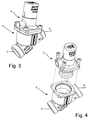
- a DPCV is shown in different views.
- the DPCV is adapted for maintaining a substantially constant differential pressure over a device, such as a heating or cooling convector, or a circuit of a number of devices, such as comprising several heating or cooling convectors.
- a device such as a heating or cooling convector, or a circuit of a number of devices, such as comprising several heating or cooling convectors.
- the functioning of the DPCV will be explained in more detail further below with reference to Fig. 9 .
- a valve housing 1 consists of a lower part 4 and an upper part 5, the upper part 5 encasing a replaceable valve insert comprising a pressure maintaining arrangement for maintaining a substantially constant differential pressure between an upstream pressure P1 and a downstream pressure P2 ( Fig. 5 ).
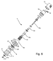
- the valve insert is shown separated from the housing part 4 in Fig. 4 and in exploded view in Fig. 6 .
- the upper housing part 5 comprises to upper housing portions 5a and 5b.
- the upper housing part 5, specifically portion 5a comprises an upstream inlet 6 for connection to a capillary tube (not shown) communicating with the upstream flow F1 ( Fig. 9 ), i.e. the flow upstream from the device or circuit.
- the upstream inlet 6 connects the valve housing 1 with an inlet I to the device, system or circuit over which the valve maintains a constant differential pressure ( Fig. 9 ).
- the valve inlet 2 communicates with a downstream flow F2 entering the valve from a downstream outlet U from the device, system or circuit over which the valve maintains a constant differential pressure ( Fig. 9 ), i.e. a flow downstream from said device or circuit.
- the valve outlet 3 communicates with an outlet flow F3.
- the upstream inlet 6 extends into the upper housing part 5 from outside of the valve housing 1 on a side opposite to the valve inlet 2 when seen in relation to a valve member 7.
- the valve member 7 forms part of the pressure maintaining arrangement, which also comprises a roller diaphragm 8.
- the valve member 7 is movable along a central axis a ( Figs 1 and 5 ) of the valve, the valve member by means of the diaphragm 8 being adapted to set itself in a balance between the upstream pressure P1 on the one hand and the downstream pressure P2 as well as a spring force on the other hand.
- valve member 7 is shaped like a cup (which is in two parts), the lower part of which forming a circumferentially extending skirt 9, the downstream flow F2 in use entering in a generally axial direction into an interior of the housing 1 and an interior or hollow of the cup through a circumferentially extending inlet orifice 10, which is coaxial with the axis a, and passing below the skirt 9 in a generally radially outwards direction (which extends at a right angle to the axis a).
- the outer diameter of the diaphragm 8 (28 mm) is a little below twice the diameter of the inlet orifice 10 (14 mm).
- the skirt 9 comprises a circumferentially extending lower part 11 ( Figs 5 , 7 and 8 ) facing a circumferentially extending valve seat 12, which is fixed in relation to the housing 1, the lower part 11 being axially movable together with the valve member such as to vary an area of an opening O ( Figs 7 and 8 ) between the skirt 9 and the valve seat 12, establishing fluid communication between the valve inlet 2 and the valve outlet 3 depending on the balance setting, i.e. the position in the axial direction of the valve member 7.
- the circumferentially extending diaphragm 8 has an outer circumferential edge, which is fixed in a groove between the lower and upper housing parts 4, 5, and an inner circumferential edge, which is fixed in a groove of the valve member 7 ( Fig. 5 ).
- a mean diameter size measured between an outer diameter size and an inner diameter size of the diaphragm 8 is substantially equal to the size of an inner diameter of the lower part 11 of the skirt 9.
- the size of an outer diameter of the diaphragm 8 (28 mm) is about 1.1 times the size of an inner diameter of the lower part 11 of the skirt 9 (25.5 mm).
- Liquid and thus pressure from the capillary tube entering into the upstream inlet 6 communicates with a narrow, circumferentially extending channel 6a and a volume V above the diaphragm 8.
- the spring force is provided by means of a spring member in the form of a (helical) spring 13 positioned on a side opposite to the valve inlet 2 in relation to the valve member 7, more specifically within a hollow interior 14 in the upper housing part 5.
- the spring force of the spring 13 is adjustable by means of an adjustment device 15, which may be rotated by means of insertion of a key into slot or orifice 16 at the outer end of the device 15.
- the adjustment device 15 further comprises a hexagonal rod 15a positioned inside spindle 15b, which again is positioned inside spindle casing 15c.
- the spring 13 is positioned encompassing the device 15 coaxially with axis a.
- the spring 13 urges the valve member 7 towards its top position in cooperation with the downstream pressure P2, against the upstream pressure exerted on top of the valve member 7 and diaphragm 8.
- the DPCV shown in the figures also comprises a number of other parts such as gaskets, screws and casings, the general structure and function of which will be immediately understandable to the skilled person when considering the drawings.
- gaskets such as (plastic) cap 21, diaphragm retaining ring 22, O-ring gaskets 23, 24 and 25, locking clip 26, washer 27a, and retaining screw 27b.
- Figs 7 and 8 show a detail D of Fig. 5 , more specifically the area in which the lower part 11 of the skirt 9 of the valve member 7 is positioned opposed to the valve seat 12.
- the DPCV is shown in an open position in which liquid is allowed to pass the valve seat 12 from the downstream flow F2 of the valve inlet 2 to the outlet flow F3 at the valve outlet 3.
- the lower part 11 comprises an abutment surface 17 extending in a radial direction for axial movement towards and away from an opposed surface 17a of the valve seat 12.
- An inner surface 18 of the lower part 11 extends in a direction parallel to axis a to face the downstream flow F2 of pressure P2 and thus block or close off part of or all flow through opening O between the lower part 11 and the valve seat 12 depending on the axial position of the valve member 7.
- An outer surface 20 of the lower part 11 is located opposed to the inner surface 18 facing the valve outlet flow F3 and extending about 0.5 to 1 mm, more specifically about 0.7 mm, at an angle of about 45 degrees to the abutment surface 17 until it reaches a further surface that extends upwards in a direction parallel to the axis a.
- An inner corner formed between the abutment surface 17 and the inner surface 18 is chamfered to establish a linear ( Fig.
- transition 19 between the abutment surface 17 and the inner surface 18, said chamfer or transition 19 extending less than a distance of 0.1 mm from the abutment surface 17 in a direction towards the inner surface 18.
- the transition 19 follows the lower part 11 to extend circumferentially about axis a.
- transition 19 is shown as curved.
- the corner or transition 19 may have other shapes than linear or curved, often it will in reality have a somewhat "undefined" shape because of the extremely small dimensions of the corner. This also applies to the other corners shown in Figs 7 and 8 ; in Fig. 8 the two corners at the ends of surface 20 are also shown as curved.
- the important feature of the corner or transition 19 is that it is very small (i.e. the corner is extremely pointed or sharp) such as to minimize the axial component of a flow force Ff exerted on it ( Figs 7, 8 ).
- the chamfer or transition 19 extends less than a distance A of 0.1 mm from the inner surface 18 in a direction towards the abutment surface 17 and less than a distance B of 0.1 mm from the abutment surface 17 in a direction towards the inner surface 18. Due to the limitations of the manufacture techniques of today, a good compromise between a small transition 19 (i.e.
- a pointed or sharp corner and manufacturing costs is about 0.03 to 0.08 mm, preferably 0.03 to 0.06 mm.
- the chamfer or transition can be defined as starting where a general angle of the surface (i.e., the chamfer surface) differs with an angle of more than about 5 degrees from a general direction of the inner 18, respectively the lower 17 surface of the lower part 11 of the skirt 9. This definition also applies to the claims.
- the distances A, B are both approximately 0.05 mm, whereby a relation between the distances A, B, respectively, to an inner diameter of an inlet pipe (not shown) leading to the valve inlet 2, corresponding to the inner diameter of the valve inlet 2 ( ⁇ 19.5 mm), is about 0.26 % for both (note that in the embodiment shown both valve inlet 2 and valve outlet 3 each are provided with inner threading for connection with inlet and outlet pipes, respectively).
- a relation between the distances A, B, respectively, to the inner diameter of the lower part 11 of the skirt 9 (25.5 mm) is similarly about 0.2 % for both.
- the size of the diameter of the lower part 11 of the skirt 9 (25.5 mm) is about 1.8 times the size of the diameter of the orifice inlet (14 mm).
- the abutment surface 17 extends a distance C of about 0.06 to 0.1 mm towards the outer surface of the skirt 9. Similar to the transition 19, it is preferable that the lower 17 surface is very small to minimize flow forces exerted on it.
- Fig. 9 shows part of a system or circuit of a heating plant of a residential building with two heating or cooling convectors 28 positioned in parallel.
- the upstream inlet 6 connects via a capillary tube 29 the DPCV housing 1, specifically the housing portion 5a, with an inlet I to the system.
- the valve inlet 2 communicates with a downstream flow F2 entering the DPCV from a downstream outlet U from the system, i.e. a flow downstream from the system. Flow is achieved by means of pump U.
- the valve outlet 3 communicates with an outlet flow F3 from the DPCV. As is visible also in Fig. 9 the pressure at the flows F1, F2 and F3 are defined as P1, P2 and P3, respectively.
- upstream liquid (water) from flow F1 enters (or, more precisely, the pressure is carried over) into the valve housing 1 via the capillary tube 29 and is led to the volume V above the diaphragm 8 via channel 6a, where upstream pressure P1 is exerted on the upper surface of the diaphragm 8.
- the DPCV maintains a substantially constant differential pressure over the system, i.e. between P1 and P2.
- the value of the constant differential pressure is determined by the setting of the spring 13.
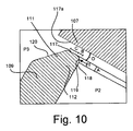
- Fig. 10 shows a view corresponding to that of Fig. 8 in an alternative embodiment of the DPCV according to the invention. More specifically, the view is a detail of the opposite, lower side of the valve member 11 compared to the detail D in Fig. 8 in an alternative embodiment of the DPCV shown in Fig. 5 .
- valve seat 112 in contrast to the previous embodiment the valve seat 112 comprises a skirt 109, and the second, opposing member is in the form of the valve member 107.
- An upper part 111 of the skirt 109 is embodied and shaped similarly to the lower part 11 of the skirt 9 in the previous embodiment, and thus comprises abutment surface 117, inner surface 118, outer surface 120 and transition 119, which in function all correspond to the corresponding reference numbers of the previous embodiment.
- An inner diameter of the skirt 109 is smaller than an outer diameter of the lower part of the valve member 107.
- the valve member 107 (or at least the lower part of this) is in this case a solid member, specifically a solid cylinder, i.e.
- This bottom surface 117a extends on the entire lower surface of the valve member, but could in principle comprise one or more indentations or be cup-shaped similar to the previous embodiment.
- the opening O as well as the distances A, B and C also correspond to those in the previous embodiment.
Landscapes
- Physics & Mathematics (AREA)
- Fluid Mechanics (AREA)
- General Physics & Mathematics (AREA)
- Engineering & Computer Science (AREA)
- Automation & Control Theory (AREA)
- Safety Valves (AREA)
Priority Applications (2)
| Application Number | Priority Date | Filing Date | Title |
|---|---|---|---|
| SI201330442A SI2898387T1 (sl) | 2012-09-20 | 2013-09-19 | Diferencialni tlačni nadzorni ventil |
| PL13770628T PL2898387T3 (pl) | 2012-09-20 | 2013-09-19 | Zawór regulacyjny różnicy ciśnień |
Applications Claiming Priority (2)
| Application Number | Priority Date | Filing Date | Title |
|---|---|---|---|
| DKPA201270579 | 2012-09-20 | ||
| PCT/DK2013/050298 WO2014044282A2 (en) | 2012-09-20 | 2013-09-19 | A differential pressure control valve |
Publications (2)
| Publication Number | Publication Date |
|---|---|
| EP2898387A2 EP2898387A2 (en) | 2015-07-29 |
| EP2898387B1 true EP2898387B1 (en) | 2016-10-12 |
Family
ID=49263075
Family Applications (1)
| Application Number | Title | Priority Date | Filing Date |
|---|---|---|---|
| EP13770628.9A Active EP2898387B1 (en) | 2012-09-20 | 2013-09-19 | A differential pressure control valve |
Country Status (5)
| Country | Link |
|---|---|
| EP (1) | EP2898387B1 (pl) |
| DK (1) | DK2898387T5 (pl) |
| PL (1) | PL2898387T3 (pl) |
| SI (1) | SI2898387T1 (pl) |
| WO (1) | WO2014044282A2 (pl) |
Cited By (1)
| Publication number | Priority date | Publication date | Assignee | Title |
|---|---|---|---|---|
| US10379549B2 (en) | 2016-10-14 | 2019-08-13 | Honeywell Technologies Sarl | Pressure independent control valve |
Families Citing this family (1)
| Publication number | Priority date | Publication date | Assignee | Title |
|---|---|---|---|---|
| IT202200002963A1 (it) * | 2022-02-17 | 2023-08-17 | Ivar Spa | Cartuccia di riduzione dinamica della pressione di un fluido e relativo dispositivo di trattamento di un fluido |
Family Cites Families (3)
| Publication number | Priority date | Publication date | Assignee | Title |
|---|---|---|---|---|
| DK160648B (da) * | 1988-08-05 | 1991-04-02 | Frese Armatur | Fremgangsmaade til regulering af et central- eller fjernvarmeanlaeg med en differenstrykventil og anlaeg til brug hertil |
| DK176350B2 (da) * | 2005-06-23 | 2008-10-13 | Frese As | Reguleringsventil |
| DK177066B1 (da) * | 2008-05-05 | 2011-05-23 | Frese As | Reguleringsventil |
-
2013
- 2013-09-19 PL PL13770628T patent/PL2898387T3/pl unknown
- 2013-09-19 EP EP13770628.9A patent/EP2898387B1/en active Active
- 2013-09-19 WO PCT/DK2013/050298 patent/WO2014044282A2/en not_active Ceased
- 2013-09-19 SI SI201330442A patent/SI2898387T1/sl unknown
- 2013-09-19 DK DK13770628.9T patent/DK2898387T5/da active
Cited By (1)
| Publication number | Priority date | Publication date | Assignee | Title |
|---|---|---|---|---|
| US10379549B2 (en) | 2016-10-14 | 2019-08-13 | Honeywell Technologies Sarl | Pressure independent control valve |
Also Published As
| Publication number | Publication date |
|---|---|
| WO2014044282A2 (en) | 2014-03-27 |
| SI2898387T1 (sl) | 2017-04-26 |
| WO2014044282A3 (en) | 2014-11-27 |
| PL2898387T3 (pl) | 2017-06-30 |
| DK2898387T5 (da) | 2022-02-28 |
| EP2898387A2 (en) | 2015-07-29 |
| DK2898387T3 (en) | 2017-01-30 |
Similar Documents
| Publication | Publication Date | Title |
|---|---|---|
| CA2920105C (en) | A flow control system and control valve having closure assistance | |
| US4080993A (en) | In-line flow-control valve | |
| EP2898386B1 (en) | Balanced regulator with inlet pressure sensing tube | |
| US20140332097A1 (en) | Flow-volume regulator | |
| US9651953B2 (en) | Flow controller | |
| EP3067772A2 (en) | Automatic balancing valve | |
| CN112361030A (zh) | 一种冷热切换动态平衡电动调节阀 | |
| EP3309643B1 (en) | Pressure independent control valve | |
| EP3365742B1 (en) | Pressure regulating device having a variable travel stop | |
| IT201900003389A1 (it) | Gruppo di regolazione a cartuccia con camera di compensazione e valvola idraulica comprendente il gruppo di regolazione a cartuccia. | |
| US20150048267A1 (en) | Anti cavitation control valve | |
| EP2898387B1 (en) | A differential pressure control valve | |
| US4887637A (en) | Pressure compensating flow control device | |
| EP2901060B1 (en) | Self-aligning valve plug | |
| EP3191909B1 (en) | Fluid regulator having a retractable sense tube | |
| JP2009074656A (ja) | 逆止機能付き定流量弁 | |
| US4066096A (en) | Flow-control valve | |
| JP5575590B2 (ja) | 減圧弁 | |
| US7128087B2 (en) | Differential pressure valve | |
| EP3708885B1 (en) | Improved dispensing cartridge for dispensing water in a water system | |
| IT202300003516A1 (it) | Cartuccia di regolazione a corsa ridotta per valvola idraulica | |
| EP3165987B1 (en) | Flushing means for valve | |
| CN110220018B (zh) | 一种单向阀 | |
| CN205036932U (zh) | 压差平衡阀 | |
| WO2006125270A1 (en) | Fluid flow regulator |
Legal Events
| Date | Code | Title | Description |
|---|---|---|---|
| PUAI | Public reference made under article 153(3) epc to a published international application that has entered the european phase |
Free format text: ORIGINAL CODE: 0009012 |
|
| 17P | Request for examination filed |
Effective date: 20150417 |
|
| AK | Designated contracting states |
Kind code of ref document: A2 Designated state(s): AL AT BE BG CH CY CZ DE DK EE ES FI FR GB GR HR HU IE IS IT LI LT LU LV MC MK MT NL NO PL PT RO RS SE SI SK SM TR |
|
| AX | Request for extension of the european patent |
Extension state: BA ME |
|
| DAX | Request for extension of the european patent (deleted) | ||
| GRAP | Despatch of communication of intention to grant a patent |
Free format text: ORIGINAL CODE: EPIDOSNIGR1 |
|
| INTG | Intention to grant announced |
Effective date: 20160415 |
|
| GRAS | Grant fee paid |
Free format text: ORIGINAL CODE: EPIDOSNIGR3 |
|
| GRAA | (expected) grant |
Free format text: ORIGINAL CODE: 0009210 |
|
| AK | Designated contracting states |
Kind code of ref document: B1 Designated state(s): AL AT BE BG CH CY CZ DE DK EE ES FI FR GB GR HR HU IE IS IT LI LT LU LV MC MK MT NL NO PL PT RO RS SE SI SK SM TR |
|
| REG | Reference to a national code |
Ref country code: GB Ref legal event code: FG4D |
|
| REG | Reference to a national code |
Ref country code: CH Ref legal event code: EP |
|
| REG | Reference to a national code |
Ref country code: AT Ref legal event code: REF Ref document number: 837059 Country of ref document: AT Kind code of ref document: T Effective date: 20161015 |
|
| REG | Reference to a national code |
Ref country code: IE Ref legal event code: FG4D |
|
| REG | Reference to a national code |
Ref country code: DE Ref legal event code: R096 Ref document number: 602013012775 Country of ref document: DE |
|
| REG | Reference to a national code |
Ref country code: NL Ref legal event code: FP |
|
| REG | Reference to a national code |
Ref country code: SE Ref legal event code: TRGR |
|
| REG | Reference to a national code |
Ref country code: DK Ref legal event code: T3 Effective date: 20170126 |
|
| REG | Reference to a national code |
Ref country code: LT Ref legal event code: MG4D |
|
| PG25 | Lapsed in a contracting state [announced via postgrant information from national office to epo] |
Ref country code: LV Free format text: LAPSE BECAUSE OF FAILURE TO SUBMIT A TRANSLATION OF THE DESCRIPTION OR TO PAY THE FEE WITHIN THE PRESCRIBED TIME-LIMIT Effective date: 20161012 |
|
| PG25 | Lapsed in a contracting state [announced via postgrant information from national office to epo] |
Ref country code: GR Free format text: LAPSE BECAUSE OF FAILURE TO SUBMIT A TRANSLATION OF THE DESCRIPTION OR TO PAY THE FEE WITHIN THE PRESCRIBED TIME-LIMIT Effective date: 20170113 Ref country code: NO Free format text: LAPSE BECAUSE OF FAILURE TO SUBMIT A TRANSLATION OF THE DESCRIPTION OR TO PAY THE FEE WITHIN THE PRESCRIBED TIME-LIMIT Effective date: 20170112 Ref country code: LT Free format text: LAPSE BECAUSE OF FAILURE TO SUBMIT A TRANSLATION OF THE DESCRIPTION OR TO PAY THE FEE WITHIN THE PRESCRIBED TIME-LIMIT Effective date: 20161012 |
|
| PG25 | Lapsed in a contracting state [announced via postgrant information from national office to epo] |
Ref country code: HR Free format text: LAPSE BECAUSE OF FAILURE TO SUBMIT A TRANSLATION OF THE DESCRIPTION OR TO PAY THE FEE WITHIN THE PRESCRIBED TIME-LIMIT Effective date: 20161012 Ref country code: PT Free format text: LAPSE BECAUSE OF FAILURE TO SUBMIT A TRANSLATION OF THE DESCRIPTION OR TO PAY THE FEE WITHIN THE PRESCRIBED TIME-LIMIT Effective date: 20170213 Ref country code: ES Free format text: LAPSE BECAUSE OF FAILURE TO SUBMIT A TRANSLATION OF THE DESCRIPTION OR TO PAY THE FEE WITHIN THE PRESCRIBED TIME-LIMIT Effective date: 20161012 Ref country code: RS Free format text: LAPSE BECAUSE OF FAILURE TO SUBMIT A TRANSLATION OF THE DESCRIPTION OR TO PAY THE FEE WITHIN THE PRESCRIBED TIME-LIMIT Effective date: 20161012 Ref country code: BE Free format text: LAPSE BECAUSE OF FAILURE TO SUBMIT A TRANSLATION OF THE DESCRIPTION OR TO PAY THE FEE WITHIN THE PRESCRIBED TIME-LIMIT Effective date: 20161012 Ref country code: IS Free format text: LAPSE BECAUSE OF FAILURE TO SUBMIT A TRANSLATION OF THE DESCRIPTION OR TO PAY THE FEE WITHIN THE PRESCRIBED TIME-LIMIT Effective date: 20170212 Ref country code: FI Free format text: LAPSE BECAUSE OF FAILURE TO SUBMIT A TRANSLATION OF THE DESCRIPTION OR TO PAY THE FEE WITHIN THE PRESCRIBED TIME-LIMIT Effective date: 20161012 |
|
| REG | Reference to a national code |
Ref country code: DE Ref legal event code: R097 Ref document number: 602013012775 Country of ref document: DE |
|
| PG25 | Lapsed in a contracting state [announced via postgrant information from national office to epo] |
Ref country code: EE Free format text: LAPSE BECAUSE OF FAILURE TO SUBMIT A TRANSLATION OF THE DESCRIPTION OR TO PAY THE FEE WITHIN THE PRESCRIBED TIME-LIMIT Effective date: 20161012 Ref country code: RO Free format text: LAPSE BECAUSE OF FAILURE TO SUBMIT A TRANSLATION OF THE DESCRIPTION OR TO PAY THE FEE WITHIN THE PRESCRIBED TIME-LIMIT Effective date: 20161012 |
|
| PLBE | No opposition filed within time limit |
Free format text: ORIGINAL CODE: 0009261 |
|
| STAA | Information on the status of an ep patent application or granted ep patent |
Free format text: STATUS: NO OPPOSITION FILED WITHIN TIME LIMIT |
|
| REG | Reference to a national code |
Ref country code: FR Ref legal event code: PLFP Year of fee payment: 5 |
|
| PG25 | Lapsed in a contracting state [announced via postgrant information from national office to epo] |
Ref country code: SM Free format text: LAPSE BECAUSE OF FAILURE TO SUBMIT A TRANSLATION OF THE DESCRIPTION OR TO PAY THE FEE WITHIN THE PRESCRIBED TIME-LIMIT Effective date: 20161012 Ref country code: BG Free format text: LAPSE BECAUSE OF FAILURE TO SUBMIT A TRANSLATION OF THE DESCRIPTION OR TO PAY THE FEE WITHIN THE PRESCRIBED TIME-LIMIT Effective date: 20170112 |
|
| 26N | No opposition filed |
Effective date: 20170713 |
|
| REG | Reference to a national code |
Ref country code: CH Ref legal event code: PL |
|
| PG25 | Lapsed in a contracting state [announced via postgrant information from national office to epo] |
Ref country code: MC Free format text: LAPSE BECAUSE OF FAILURE TO SUBMIT A TRANSLATION OF THE DESCRIPTION OR TO PAY THE FEE WITHIN THE PRESCRIBED TIME-LIMIT Effective date: 20161012 |
|
| REG | Reference to a national code |
Ref country code: IE Ref legal event code: MM4A |
|
| PG25 | Lapsed in a contracting state [announced via postgrant information from national office to epo] |
Ref country code: LU Free format text: LAPSE BECAUSE OF NON-PAYMENT OF DUE FEES Effective date: 20170919 |
|
| PG25 | Lapsed in a contracting state [announced via postgrant information from national office to epo] |
Ref country code: IE Free format text: LAPSE BECAUSE OF NON-PAYMENT OF DUE FEES Effective date: 20170919 Ref country code: CH Free format text: LAPSE BECAUSE OF NON-PAYMENT OF DUE FEES Effective date: 20170930 Ref country code: LI Free format text: LAPSE BECAUSE OF NON-PAYMENT OF DUE FEES Effective date: 20170930 |
|
| REG | Reference to a national code |
Ref country code: FR Ref legal event code: PLFP Year of fee payment: 6 |
|
| PG25 | Lapsed in a contracting state [announced via postgrant information from national office to epo] |
Ref country code: MT Free format text: LAPSE BECAUSE OF NON-PAYMENT OF DUE FEES Effective date: 20170919 |
|
| PG25 | Lapsed in a contracting state [announced via postgrant information from national office to epo] |
Ref country code: HU Free format text: LAPSE BECAUSE OF FAILURE TO SUBMIT A TRANSLATION OF THE DESCRIPTION OR TO PAY THE FEE WITHIN THE PRESCRIBED TIME-LIMIT; INVALID AB INITIO Effective date: 20130919 |
|
| REG | Reference to a national code |
Ref country code: AT Ref legal event code: UEP Ref document number: 837059 Country of ref document: AT Kind code of ref document: T Effective date: 20161012 |
|
| PG25 | Lapsed in a contracting state [announced via postgrant information from national office to epo] |
Ref country code: CY Free format text: LAPSE BECAUSE OF FAILURE TO SUBMIT A TRANSLATION OF THE DESCRIPTION OR TO PAY THE FEE WITHIN THE PRESCRIBED TIME-LIMIT Effective date: 20161012 |
|
| PG25 | Lapsed in a contracting state [announced via postgrant information from national office to epo] |
Ref country code: MK Free format text: LAPSE BECAUSE OF FAILURE TO SUBMIT A TRANSLATION OF THE DESCRIPTION OR TO PAY THE FEE WITHIN THE PRESCRIBED TIME-LIMIT Effective date: 20161012 |
|
| PG25 | Lapsed in a contracting state [announced via postgrant information from national office to epo] |
Ref country code: AL Free format text: LAPSE BECAUSE OF FAILURE TO SUBMIT A TRANSLATION OF THE DESCRIPTION OR TO PAY THE FEE WITHIN THE PRESCRIBED TIME-LIMIT Effective date: 20161012 |
|
| REG | Reference to a national code |
Ref country code: DE Ref legal event code: R082 Ref document number: 602013012775 Country of ref document: DE Representative=s name: KILBURN & STRODE LLP, NL |
|
| REG | Reference to a national code |
Ref country code: DK Ref legal event code: T5 Effective date: 20220224 |
|
| P01 | Opt-out of the competence of the unified patent court (upc) registered |
Effective date: 20230529 |
|
| PGFP | Annual fee paid to national office [announced via postgrant information from national office to epo] |
Ref country code: DE Payment date: 20250917 Year of fee payment: 13 Ref country code: DK Payment date: 20250915 Year of fee payment: 13 |
|
| PGFP | Annual fee paid to national office [announced via postgrant information from national office to epo] |
Ref country code: PL Payment date: 20250814 Year of fee payment: 13 Ref country code: TR Payment date: 20250915 Year of fee payment: 13 Ref country code: NL Payment date: 20250916 Year of fee payment: 13 Ref country code: IT Payment date: 20250808 Year of fee payment: 13 |
|
| PGFP | Annual fee paid to national office [announced via postgrant information from national office to epo] |
Ref country code: GB Payment date: 20250915 Year of fee payment: 13 |
|
| PGFP | Annual fee paid to national office [announced via postgrant information from national office to epo] |
Ref country code: FR Payment date: 20250916 Year of fee payment: 13 Ref country code: AT Payment date: 20250917 Year of fee payment: 13 |
|
| PGFP | Annual fee paid to national office [announced via postgrant information from national office to epo] |
Ref country code: SE Payment date: 20250916 Year of fee payment: 13 |
|
| PGFP | Annual fee paid to national office [announced via postgrant information from national office to epo] |
Ref country code: CZ Payment date: 20250912 Year of fee payment: 13 |
|
| PGFP | Annual fee paid to national office [announced via postgrant information from national office to epo] |
Ref country code: SK Payment date: 20250916 Year of fee payment: 13 |
|
| PGFP | Annual fee paid to national office [announced via postgrant information from national office to epo] |
Ref country code: SI Payment date: 20250911 Year of fee payment: 13 |