EP2897498B1 - Chair assembly - Google Patents
Chair assembly Download PDFInfo
- Publication number
- EP2897498B1 EP2897498B1 EP13838698.2A EP13838698A EP2897498B1 EP 2897498 B1 EP2897498 B1 EP 2897498B1 EP 13838698 A EP13838698 A EP 13838698A EP 2897498 B1 EP2897498 B1 EP 2897498B1
- Authority
- EP
- European Patent Office
- Prior art keywords
- chair
- assembly
- chair member
- component
- drawstring
- Prior art date
- Legal status (The legal status is an assumption and is not a legal conclusion. Google has not performed a legal analysis and makes no representation as to the accuracy of the status listed.)
- Active
Links
- 239000004744 fabric Substances 0.000 claims description 5
- 230000002787 reinforcement Effects 0.000 description 5
- 230000000712 assembly Effects 0.000 description 4
- 238000000429 assembly Methods 0.000 description 4
- UQMRAFJOBWOFNS-UHFFFAOYSA-N butyl 2-(2,4-dichlorophenoxy)acetate Chemical compound CCCCOC(=O)COC1=CC=C(Cl)C=C1Cl UQMRAFJOBWOFNS-UHFFFAOYSA-N 0.000 description 4
- 239000000463 material Substances 0.000 description 4
- 238000000034 method Methods 0.000 description 4
- NJPPVKZQTLUDBO-UHFFFAOYSA-N novaluron Chemical compound C1=C(Cl)C(OC(F)(F)C(OC(F)(F)F)F)=CC=C1NC(=O)NC(=O)C1=C(F)C=CC=C1F NJPPVKZQTLUDBO-UHFFFAOYSA-N 0.000 description 3
- 239000006260 foam Substances 0.000 description 2
- 238000012986 modification Methods 0.000 description 2
- 230000004048 modification Effects 0.000 description 2
- 239000004033 plastic Substances 0.000 description 2
- 229920002725 thermoplastic elastomer Polymers 0.000 description 2
- 239000000853 adhesive Substances 0.000 description 1
- 230000001070 adhesive effect Effects 0.000 description 1
- 239000006261 foam material Substances 0.000 description 1
- 239000002184 metal Substances 0.000 description 1
- 230000002093 peripheral effect Effects 0.000 description 1
- 238000009958 sewing Methods 0.000 description 1
Images


Classifications
-
- A—HUMAN NECESSITIES
- A47—FURNITURE; DOMESTIC ARTICLES OR APPLIANCES; COFFEE MILLS; SPICE MILLS; SUCTION CLEANERS IN GENERAL
- A47C—CHAIRS; SOFAS; BEDS
- A47C1/00—Chairs adapted for special purposes
- A47C1/02—Reclining or easy chairs
- A47C1/022—Reclining or easy chairs having independently-adjustable supporting parts
- A47C1/024—Reclining or easy chairs having independently-adjustable supporting parts the parts, being the back-rest, or the back-rest and seat unit, having adjustable and lockable inclination
-
- A—HUMAN NECESSITIES
- A47—FURNITURE; DOMESTIC ARTICLES OR APPLIANCES; COFFEE MILLS; SPICE MILLS; SUCTION CLEANERS IN GENERAL
- A47C—CHAIRS; SOFAS; BEDS
- A47C31/00—Details or accessories for chairs, beds, or the like, not provided for in other groups of this subclass, e.g. upholstery fasteners, mattress protectors, stretching devices for mattress nets
- A47C31/02—Upholstery attaching means
-
- A—HUMAN NECESSITIES
- A47—FURNITURE; DOMESTIC ARTICLES OR APPLIANCES; COFFEE MILLS; SPICE MILLS; SUCTION CLEANERS IN GENERAL
- A47C—CHAIRS; SOFAS; BEDS
- A47C31/00—Details or accessories for chairs, beds, or the like, not provided for in other groups of this subclass, e.g. upholstery fasteners, mattress protectors, stretching devices for mattress nets
- A47C31/10—Loose or removable furniture covers
- A47C31/11—Loose or removable furniture covers for chairs
-
- A—HUMAN NECESSITIES
- A47—FURNITURE; DOMESTIC ARTICLES OR APPLIANCES; COFFEE MILLS; SPICE MILLS; SUCTION CLEANERS IN GENERAL
- A47C—CHAIRS; SOFAS; BEDS
- A47C7/00—Parts, details, or accessories of chairs or stools
- A47C7/02—Seat parts
-
- A—HUMAN NECESSITIES
- A47—FURNITURE; DOMESTIC ARTICLES OR APPLIANCES; COFFEE MILLS; SPICE MILLS; SUCTION CLEANERS IN GENERAL
- A47C—CHAIRS; SOFAS; BEDS
- A47C7/00—Parts, details, or accessories of chairs or stools
- A47C7/36—Support for the head or the back
- A47C7/40—Support for the head or the back for the back
- A47C7/405—Support for the head or the back for the back with double backrests
-
- A—HUMAN NECESSITIES
- A47—FURNITURE; DOMESTIC ARTICLES OR APPLIANCES; COFFEE MILLS; SPICE MILLS; SUCTION CLEANERS IN GENERAL
- A47C—CHAIRS; SOFAS; BEDS
- A47C7/00—Parts, details, or accessories of chairs or stools
- A47C7/36—Support for the head or the back
- A47C7/40—Support for the head or the back for the back
- A47C7/46—Support for the head or the back for the back with special, e.g. adjustable, lumbar region support profile; "Ackerblom" profile chairs
-
- Y—GENERAL TAGGING OF NEW TECHNOLOGICAL DEVELOPMENTS; GENERAL TAGGING OF CROSS-SECTIONAL TECHNOLOGIES SPANNING OVER SEVERAL SECTIONS OF THE IPC; TECHNICAL SUBJECTS COVERED BY FORMER USPC CROSS-REFERENCE ART COLLECTIONS [XRACs] AND DIGESTS
- Y10—TECHNICAL SUBJECTS COVERED BY FORMER USPC
- Y10T—TECHNICAL SUBJECTS COVERED BY FORMER US CLASSIFICATION
- Y10T29/00—Metal working
- Y10T29/48—Upholstered article making
- Y10T29/481—Method
-
- Y—GENERAL TAGGING OF NEW TECHNOLOGICAL DEVELOPMENTS; GENERAL TAGGING OF CROSS-SECTIONAL TECHNOLOGIES SPANNING OVER SEVERAL SECTIONS OF THE IPC; TECHNICAL SUBJECTS COVERED BY FORMER USPC CROSS-REFERENCE ART COLLECTIONS [XRACs] AND DIGESTS
- Y10—TECHNICAL SUBJECTS COVERED BY FORMER USPC
- Y10T—TECHNICAL SUBJECTS COVERED BY FORMER US CLASSIFICATION
- Y10T29/00—Metal working
- Y10T29/48—Upholstered article making
- Y10T29/486—Cover stretching
-
- Y—GENERAL TAGGING OF NEW TECHNOLOGICAL DEVELOPMENTS; GENERAL TAGGING OF CROSS-SECTIONAL TECHNOLOGIES SPANNING OVER SEVERAL SECTIONS OF THE IPC; TECHNICAL SUBJECTS COVERED BY FORMER USPC CROSS-REFERENCE ART COLLECTIONS [XRACs] AND DIGESTS
- Y10—TECHNICAL SUBJECTS COVERED BY FORMER USPC
- Y10T—TECHNICAL SUBJECTS COVERED BY FORMER US CLASSIFICATION
- Y10T29/00—Metal working
- Y10T29/49—Method of mechanical manufacture
- Y10T29/49826—Assembling or joining
- Y10T29/4984—Retaining clearance for motion between assembled parts
-
- Y—GENERAL TAGGING OF NEW TECHNOLOGICAL DEVELOPMENTS; GENERAL TAGGING OF CROSS-SECTIONAL TECHNOLOGIES SPANNING OVER SEVERAL SECTIONS OF THE IPC; TECHNICAL SUBJECTS COVERED BY FORMER USPC CROSS-REFERENCE ART COLLECTIONS [XRACs] AND DIGESTS
- Y10—TECHNICAL SUBJECTS COVERED BY FORMER USPC
- Y10T—TECHNICAL SUBJECTS COVERED BY FORMER US CLASSIFICATION
- Y10T29/00—Metal working
- Y10T29/49—Method of mechanical manufacture
- Y10T29/49826—Assembling or joining
- Y10T29/49947—Assembling or joining by applying separate fastener
- Y10T29/49954—Fastener deformed after application
Definitions
- the present invention relates to a chair assembly, and in particular to an office chair assembly comprising a back assembly including an upholstery arrangement that wraps about a front surface and a rear surface of the back assembly.
- the present invention is to provide a chair component that comprises a first chair member adapted to support a seated user, a second chair member movable between a first position, wherein the second chair component is substantially coplanar with the first chair member, and a second position, wherein the second chair member is substantially parallel with the first chair member, a cover member wrapped about at least a portion of the first chair member and at least a portion of the second chair member, and a single-piece drawstring operably coupled with the cover member to draw the cover member about the at least a portion of the first chair member and the at least a portion of the second chair member when the second chair member is in the first position, and wherein the cover member remains wrapped about the at least a portion of the first chair member and about the at least a portion of the second chair member as the second chair member is moved from the first position to the second position.
- An example that is not part of the present invention is to provide a method of assembling a chair component that comprises providing a first chair member adapted to support a seated user, providing a second chair member movable between a first position, wherein the second chair member is substantially coplanar with the first chair member, and a second position, wherein the second chair member is substantially parallel with the first chair member, and wrapping a cover member about at least a portion of the first chair member and at least a portion of the second chair member.
- the method further comprises providing a drawstring operably coupled with the cover member, drawing the cover member about the at least a portion of the first chair member and the at least a portion of the second chair member when the second chair member is in the first position, fixing an effective length of the drawstring while the second chair member is in the first position, moving the second chair member from the first position to the second position, and securing the second chair member in the second position.
- Various elements of the embodiments disclosed herein may be described as being operably coupled to one another, which includes elements either directly or indirectly coupled to one another.
- the term "chair” as utilized herein encompasses various seating arrangements, including office chairs, vehicle seating, home seating, stadium seating, theater seating, and the like.
- the reference numeral 10 ( Figs. 1 and 2 ) generally designates a chair assembly embodying the present invention.
- the chair assembly 10 includes a castered base assembly 12 abutting a supporting floor surface 13, a control or support assembly 14 supported by the castered base assembly 12, a seat assembly 16 and back assembly 18 each operably coupled with the control assembly 14, and a pair of arm assemblies 20.
- the control assembly 14 ( Fig. 3 ) is operably coupled to the base assembly 12 such that the seat assembly 16, the back assembly 18 and the arm assemblies 20 may be vertically adjusted between a fully lowered position A and a fully raised position B, and pivoted about a vertical axis 21 in a direction 22.
- the seat assembly 16 is operably coupled to the control assembly 14 such that the seat assembly 16 is longitudinally adjustable with respect to the control assembly 14 between a fully retracted position C and a fully extended position D.
- the seat assembly 16 ( Fig. 4 ) and the back assembly 18 are operably coupled with the control assembly 14 and with one another such that the back assembly 18 is movable between a fully upright position E and a fully reclined position F, and further such that the seat assembly 16 is movable between a fully upright position G and a fully reclined position H corresponding to the fully upright position E and the fully reclined position F of the back assembly 18, respectively.
- the base assembly 12 includes a plurality of pedestal arms 24 radially extending and spaced about a hollow central column 26 that receives a pneumatic cylinder 28 therein. Each pedestal arm 24 is supported above the floor surface 13 by an associated caster assembly 30. Although the base assembly 12 is illustrated as including a multiple-arm pedestal assembly, it is noted that other suitable supporting structures may be utilized, including but not limited to fixed columns, multiple leg arrangements, vehicle seat support assemblies, and the like.
- the seat assembly 16 ( Fig. 5 ) includes a relatively rigid seat support plate 32 having a forward edge 34, a rearward edge 36, and a pair of C-shaped guide rails 38 defining the side edges of the seat support plate 32 and extending between the forward edge 34 and the rearward edge 36.
- the seat assembly 16 further includes a flexibly resilient outer seat shell 40 having a pair of upwardly turned side portions 42 and an upwardly turned rear portion 44 that cooperate to form an upwardly disposed generally concave shape.
- the seat shell 40 is comprised of a relatively flexible material such as a thermoplastic elastomer (TPE).
- the outer seat shell 40 is secured and sandwiched between the seat support plate 32 and a plastic, flexibly resilient seat pan 46 which is secured to the seat support plate 32 by a plurality of mechanical fasteners.
- the seat pan 46 includes a forward edge 48, a rearward edge 50, side edges 52 extending between the forward edge 48 and the rearward edge 50, a top surface 54 and a bottom surface 56 that cooperate to form an upwardly disposed generally concave shape.
- the seat pan 46 includes a plurality of longitudinally extending slots 58 extending forwardly from the rearward edge 50. The slots 58 cooperate to define a plurality of fingers 60 therebetween, each finger 60 being individually flexibly resilient.
- the seat pan 46 further includes a plurality of laterally oriented, elongated apertures 62 located proximate the forward edge 48.
- the apertures 62 cooperate to increase the overall flexibility of the seat pan 46 in the area thereof, and specifically allow a forward portion 64 of the seat pan 46 to flex in a vertical direction 66 with respect to a rearward portion 68 of the seat pan 46, as discussed further below.
- the seat assembly 16 further includes a foam cushion member 70 that rests upon the top surface 54 of the seat pan 46 and is cradled within the outer seat shell 40, a fabric seat cover 72, and an upper surface 76 of the cushion members 70.
- a spring support assembly 78 ( Figs.
- the spring support assembly 78 includes a support housing 80 comprising a foam and having side portions 82 defining an upwardly concave arcuate shape.
- the spring support assembly 78 further includes a relatively rigid attachment member 84 that extends laterally between the side portions 82 of the support housing 80 and is located between the support housing 80 and the forward portion 64 of the seat pan 46.
- a plurality of mechanical fasteners 86 secure the support housing 80 and the attachment member 84 to the forward portion 64 of the seat pan 46.
- the spring support assembly 78 further includes a pair of cantilever springs 88 each having a distal end 90 received through a corresponding aperture 92 of the attachment member 84, and a proximate end 94 secured to the seat support plate 32 such that the distal end 90 of each cantilever spring 88 may flex in the vertical direction 66.
- a pair of linear bearings 96 are fixedly attached to the attachment member 84 and aligned with the apertures 92 thereof, such that the linear bearing 96 slidably receives the distal ends 90 of a corresponding cantilever spring 88.
- the cantilever springs 88 cooperate to allow the forward portion 64 of the seat pan 46, and more generally the entire forward portion of seat assembly 16 to flex in the vertical direction 66 when a seated user rotates forward on the seat assembly 16 and exerts a downward force on the forward edge thereof.
- the back assembly 18 ( Figs. 7-9B ) includes a back frame assembly 98 and a back support assembly 99 supported thereby.
- the back frame assembly 98 is generally comprised of a substantially rigid material such as metal, and includes a laterally extending top frame portion 100, a laterally extending bottom frame portion 102, and a pair of curved side frame portions 104 extending between the top frame portion 100 and the bottom frame portion 102 and cooperating therewith to define an opening 106 having a relatively large upper dimension 108 and a relatively narrow lower dimension 110.
- the back assembly 18 further includes a flexibly resilient, plastic back shell 112 that includes a forwardly-located first portion 119 having an upper portion 114 with an upper edge 121, a lower portion 116, a pair of side edges 118 extending between the upper portion 114 and a lower portion 116, a forwardly facing surface 120 and a rearwardly facing surface 122, wherein the width of the upper portion 114 is generally greater than the width of the lower portion 116, and the lower portion 116 is downwardly tapered to generally follow the rear elevational configuration of the frame assembly 98.
- the back shell 112 further includes a rearwardly-located second portion 123 having an upper edge 125, a lower edge 127 and a pair of side edges 129 extending between the upper edge 125 and the lower edge 127.
- the second portion 123 is generally aligned with the upper portion 114 of the first portion 119 such that the upper edge 125 and the side edges 129 of the second portion 123 are generally aligned with the upper edge 121 and the side edges 118 of the first portion 119, respectively, as described below.
- a lower reinforcement member 115 attaches to hooks 117 ( Fig. 9A ) of lower portion 116 of the first portion 119 of the back shell 112.
- Reinforcement member 115 includes a plurality of protrusions 113 that engage reinforcement ribs 134 to prevent side-to-side movement of lower reinforcement member 115 relative to the back shell 112.
- the first portion 119 of the back shell 112 also includes a plurality of integrally molded, forwardly and upwardly extending hooks 124 ( Fig. 10 ) spaced about the periphery of the upper portion 114 thereof.
- An intermediate or lumbar portion 126 is located vertically between the upper portion 114 and the lower portion 116 of the first portion 119 of the back shell 112, and includes a plurality of laterally extending slots 128 that cooperate to form a plurality of laterally extending ribs 130 located therebetween.
- the slots 128 cooperate to provide additional flexure to the back shell 112 in the location thereof. Pairings of lateral ribs 130 are coupled by vertically extending ribs 132 integrally formed therewith and located at an approximate lateral midpoint thereof.
- the vertical ribs 132 function to tie the lateral ribs 130 together and reduce vertical spreading therebetween as the back shell 112 is flexed at the intermediate portion 126 thereof when the back assembly 18 is moved from the upright position E to the reclined position F, as described further below.
- the first portion 119 of the back shell 112 further includes a plurality of laterally-spaced reinforcement ribs 134 extending longitudinally along the vertical length of the first portion 119 between the lower portion 116 and the intermediate portion 126. It is noted that the depth of each of the ribs 134 increases the further along each of the ribs 134 from the intermediate portion 126, such that the overall rigidity of the back shell 112 increases along the length of the ribs from the intermediate portion 126 toward the lower portion 116.
- the first portion 119 of the back shell 112 further includes a pair of rearwardly extending, integrally molded pivot bosses 138 forming part of an upper back pivot assembly 140.
- the back pivot assembly 140 ( Figs. 11 and 12 ) includes the pivot bosses 138 of the back shell 112, a pair of shroud members 142 that encompass respective pivot bosses 138, a race member 144, and a mechanical fastening assembly 146.
- Each pivot boss 138 includes a pair of side walls 148 and a rearwardly-facing concave seating surface 150 having a vertically elongated pivot slot 152 extending therethrough.
- Each shroud member 142 is shaped so as to closely house the corresponding pivot boss 138, and includes a plurality of side walls 154 corresponding to side walls 148, and a rearwardly-facing concave bearing surface 156 that includes a vertically elongated pivot slot extending therethrough, and which is adapted to align with the slot 152 of a corresponding pivot boss 138.
- the race member 144 includes a center portion 158 extending laterally along and abutting the top frame portion 100 of the back frame assembly 98, and a pair of arcuately-shaped bearing surfaces 160 located at the ends thereof.
- the center portion 158 includes a first portion 162, and a second portion 164, wherein the first portion 162 abuts a front surface of the top frame portion 100 and second portion 164 abuts a top surface of the top frame portion 100.
- Each bearing surface 160 includes an aperture 166 extending therethrough.
- the shroud members 142 are positioned about the corresponding pivot bosses 138 of the back shell 112 and operably positioned between the first portion 119 of the back shell 112 and race member 144 such that the bearing surface 156 is sandwiched between the seating surface 150 of a corresponding pivot boss 138 and a bearing surface 160.
- the mechanical fastening assemblies 146 each include a bolt 172 that secures a rounded abutment surface 174 of the bearing washer 176 in sliding engagement with an inner surface 178 of the corresponding pivot boss 138, and threadably engages a corresponding boss member 168 of the back frame assembly 98.
- the upper back pivot assembly 140 allows the back support assembly 99 to pivot with respect to the back frame assembly in a direction 180 ( Fig. 8 ) about a pivot axis 182 ( Fig. 7 ).
- the back support assembly 99 ( Figs. 9A and 9B ) further includes a flexibly resilient comfort member 184 ( Figs. 15A and 15B ) attached to the back shell 112 and slidably supporting a lumbar assembly 186.
- the comfort member 184 includes an upper portion 188, a lower portion 190, a pair of side portions 192 having a plurality of apertures 189 spaced therealong to increase the flexure thereof, a forward surface 193 and a rearward surface 195, wherein the upper portion 188, the lower portion 190 and the side portions cooperate to form an aperture 194 that receives the lumbar assembly 186 therein. As best illustrated in Figs.
- the comfort member 184 includes a plurality of box-shaped couplers 196 spaced about the periphery of the upper portion 188 and extending rearwardly from the rearward surface 195.
- Each box-shaped coupler 196 includes a pair of side walls 198, a top wall 200 and a rear wall 204 that cooperate to form an interior space 202.
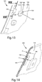
- the comfort member 184 ( Figs. 12-14 ) is secured to the back shell 112 by aligning and vertically inserting the hooks 124 of the back shell 112 into the interior space 202 of each of the box-shaped couplers 196.
- the comfort member 184 further includes a plurality of upholstery alignment and connection pads 199 extending rearwardly from the rearward surface 195 and spaced about the outer periphery of the comfort member 184. As best illustrated in Fig. 14 , the thickness t of the comfort member 184 in the region of the pads 199 is greater than the thickness t ⁇ of the comfort member 184 in other regions of the comfort member 184. In the illustrated example, the majority of the area of the comfort member 184 comprises the thickness t ⁇ .
- the pads 199 function to increase the structural rigidity of the comfort member 184 in the areas of the upholstery arrangement is attached thereto, as well as to provide alignment features for properly aligning the upholstery arrangement with respect to the comfort member 184 during assembly, as described below.
- the comfort member 184 ( Figs. 15A and 15B ) includes an integrally molded, longitudinally extending sleeve 206 extending rearwardly from the rearward surface 195 and having a rectangularly-shaped cross-sectional configuration.
- the lumbar assembly 186 includes a forwardly laterally concave and forwardly vertically convex, flexibly resilient body portion 208, and an integral support portion 210 extending upwardly from the body portion 208.
- the body portion 208 is shaped such that the body portion 208 vertically tapers along the height thereof so as to generally follow the contours and shape of the aperture 194 of the comfort member 184.
- the support portion 210 is slidably received within the sleeve 206 of the comfort member 184 such that the lumbar assembly 186 is vertically adjustable with respect to the remainder of the back support assembly 99 between a fully lowered position I and a fully raised position J.
- a pawl member 212 selectively engages a plurality of apertures 214 spaced along the length of support portion 210, thereby releasably securing the lumbar assembly 186 at selected vertical positions between the fully lowered position I and the fully raised position J.
- the pawl member 212 ( Figs. 16A and 16B ) includes a housing portion 216 having engagement tabs 218 located at the ends thereof and rearwardly offset from an outer surface 220 of the housing portion 216.
- a flexibly resilient finger 222 is centrally disposed within the housing portion 216 and includes a rearwardly-extending pawl 224.
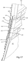
- the pawl member 212 ( Fig. 17 ) is positioned within an aperture 226 located within the upper portion 188 of the comfort member 184 such that the outer surface 220 of the housing portion 216 of the pawl member 212 is coplanar with the forward surface 193 of the comfort member 184, and such that the engagement tabs 218 of the housing portion 216 abut the rearward surface 195 of the comfort member 184.
- the support portion 210 of the lumbar assembly 186 is then positioned within the sleeve 206 of the comfort member 184 such that the sleeve 206 is slidable therein and the pawl 224 is selectively engageable with the apertures 214, thereby allowing the user to optimize the position of the lumbar assembly 186 with respect to the overall back support assembly 99.
- the body portion 208 of the lumbar assembly 186 includes a pair of outwardly extending integral handle portions 251 ( Fig. 18D ) each having a C-shaped cross-sectional configuration that wraps about and guides along the respective side edge 192 of the back shell 112.
- a user adjusts the relative vertical position of the lumbar assembly 186 with respect to the back shell 112 by grasping one or both of the handle portions 251 and sliding the handle assembly 251 along the back shell 184 in a vertical direction.
- a stop tab 228 is integrally formed within a distal end 230 and is offset therefrom so as to engage an end wall of the sleeve 206 of the comfort member 184, thereby limiting the vertical downward travel of the support portion 210 of the lumbar assembly 186 with respect to the sleeve 206 of the comfort member 184.
- the back support assembly 99 ( Figs. 9A and 9B ) also includes a cushion member 252 having an upper portion 254 and a lower portion 256, wherein the lower portion 256 tapers along the vertical length thereof to correspond to the overall shape and taper of the back shell 112 and the comfort member 184, and a topper cushion 253 comprising a relatively thin foam material.
- the back support assembly 99 ( Fig. 18A ) further includes an upholstery arrangement or cover assembly 300 that houses the back shell 112, the lumbar support assembly 186, the cushion member 252 and a topper cushion 253 therein.
- the cover assembly 300 comprises a fabric material that may be elastically deformable in one or more directions.
- the cover assembly 300 includes a front side 302 and a rear side 304 that are sewn together along the respective side edges thereof to form a first pocket 306 having a first interior or inner space 308 that receives the comfort member 184, the cushion member 252 and the topper cushion 253 therein, and a flap portion 310 that is sewn to the rear side 304 and cooperates therewith to form a second pocket 348 having a second interior or inner space 350 that receives the lumbar support assembly 186 therein.
- the cushion member 252, the comfort member 184 and the second portion 123 of the back shell 112 are assembled with the topper cushion 253 prior to assembly with the cover assembly 300, and specifically are attached to a rear surface of the topper cushion 253 via an adhesive.
- the first pocket 306 is formed by attaching the respective side edges of the front side 302 and the rear side 304 to one another such as by sewing or other means suitable for the material for which the cover assembly 300 is comprised, and to define the first interior space 308. An edge of the flap portion 310 is then secured to the rear side 304 proximate a midsection 312 thereof.
- the comfort member 184 and the second portion 123 of the back shell 112 are placed within a fixture 301 ( Fig. 18B ) that holds the second portion 123 in a planar relationship to the comfort member 184.
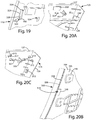
- the upholstery cover assembly 300 is stretched about the cushion member 252, the second portion 123 of the back shell 112 and the comfort member 184, and is secured to the comfort member 184 by a plurality of apertures 320 that receive upwardly extending hook members 324 ( Fig. 19 ) therethrough.
- the cover assembly 300 may be configured such that apertures 320 are positioned to also receive T-shaped attachment members 322 therethrough.
- the attachment members 322 and the hook members 324 are integrally formed with the comfort member 184.
- Each attachment member 322 is provided with a T-shaped cross-section or boat-cleat configuration having a first portion 328 extending perpendicularly rearward from within a recess 329 of the rear surface 256 of the comfort member 184, and a pair of second portions 330 located at a distal end of the first portion 328 and extending outwardly therefrom in opposite relation to one another.
- One of the second portions 330 cooperates with the first portion 328 to form an angled engagement surface 332.
- the recess 329 defines an edge 334 about the perimeter thereof.
- the cover assembly 300 is further secured to the comfort member 184 by a single, continuous drawstring 336 that extends through a drawstring tunnel 338 of the cover assembly 300, which is captured within multiple attachment features of the second portion 123 of the back shell 112 and the comfort member 184 and is in turn secured to the attachment members 322.
- the drawstring 336 and drawstring tunnel 338 are aligned with and secured to the plurality of upholstery alignment and connection pads 199' ( Fig. 20A ) similar to the pads 199 ( Fig. 20B ) of the comfort member 184 via a plurality of staples (not shown).
- the drawstring 336 and drawstring tunnel 338 are routed about hook members 313 ( Fig.
- the drawstring 336 and drawstring tunnel 338 are then aligned with the pads 199 of the second portion 123 to assure proper alignment of the cover assembly 300 with the back shell 112 and the overall back support assembly 99.
- the drawstring 336 and drawstring tunnel 338 are secured to the second portion via a plurality of staples 319 which are inserted into the thicker pads 199.
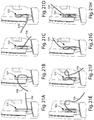
- the drawstring 336 is drawn taut and each free end of the drawstring 336 is then secured to an associated attachment member 322 in a knot-free manner and without the use of a mechanical fastener that is separate from the comfort member 184, thereby fixing the effective length of the drawstring 336 through the remainder of the assembly process.
- the drawstring 336 is wrapped about the associated attachment member 322 such that the tension in the drawstring 336 about the attachment member 322 forces the drawstring 336 against the engagement surface 332 that angles towards the recess 329, thereby forcing a portion of the drawstring 336 into the recess 329 and into engagement with at least a portion of the edge 334 of the recess 329 resulting in an increased frictional engagement between the drawstring 336 and the comfort member 184.
- the lumbar assembly 186 is then aligned with the assembly of the cover assembly 300, the cushion member 252 and the comfort member 184 such that the body portion 272 of the lumbar assembly 186 is located near the midsection 312 of the cover assembly 300, and the support portion 210 of the lumbar assembly 186 is coupled with the comfort member 184 as described above.
- the flap portion 310 is then folded over the lumbar assembly 186, thereby creating the additional pocket 348 ( Fig. 18D ) having the interior space 350.
- a distally located edge 352 of the flap portion 310 is attached to the comfort member 184 by a plurality of apertures 354 with the flap portion 310 that receive the hooks 324 therethrough.
- the distal edge 352 may also be sewn to the rear side 304 of the cover assembly 300.
- the side edges 356 of the flap portion 310 are not attached to the remainder of the cover assembly 300, such that the side edges 356 cooperate with the remainder of the cover assembly 300 to form slots 360 through the handle portions 251 of the lumbar assembly 186.
- the second pocket 348 is configured such that the lumbar assembly 186 is vertically adjustable therein.
- the assembly of the cover assembly 300, the cushion member 252, the comfort member 184, the lumbar assembly 186 and the second portion 123 of the back shell 112 are then attached to the first portion 119 of the back shell 112.
- the comfort member 184 and the second portion 123 of the back shell 112 are removed from the associated fixture (301), and the comfort member 184 is then attached to the first portion of the back shell via the hooks 124 and box-shaped couplers 196 as previously described.
- the second portion 123 of the back shell 112 is then rotated about the first portion 119 of the back shell 112 from a position where the second portion 123 is generally planar with the first portion 119, as shown in Fig.
- the second portion 123 includes a plurality of rearwardly-extending T-shaped couplers 321, while the first portion includes a plurality of cooperating slots 323 that releasably receive the couplers 321 therein, thereby securing the second portion 123 in the second position.
- Proper alignment of the second portion 123 with the first portion 119 is provided via generally conically-shaped locators 351 ( Fig. 20A ) extending forwardly from the second portion 123 that locate and align with corresponding conically-shaped recesses 355 ( Fig. 24 ) extending into the rear surface of the first portion 119 of the back shell 112.
- the back assembly 18 is further configured to increase the comfort of the outer edges of the back support assembly 99 and improve the aesthetics thereof.
- the flexibly resilient comfort member 184 includes a recessed pocket 400 that receives the cushion member 252 therein, such that the outer edge of the cushion member 252 is spaced inwardly from the outer edge of the comfort member 184, thereby providing an aesthetically clean appearance to the outer peripheral edge of the overall back support assembly 99.
- the back assembly 18 ( Fig. 4 ) is reclinable between an upright position E and a reclined position F.
- a gap 402 opens between the top frame portion 100 of the frame assembly 98 and the lower edge 127 of the second portion 123 of the back shell 112, as a result of flexure of the back support assembly 99 and pivoting of the back support assembly 99 about the pivot axis 182 in the direction 180.
- a shield member 406 ( Figs. 12 and 24 ) prevents access to the gap 402, thereby reducing or eliminating a potential pinch-point for the user.
- the shield member 406 includes a body portion 408 secured to a rear surface of the first portion 119 of the back shell 112 by a plurality of screws 410 received within rearwardly-extending bosses 412 of the shield member 406.
- the shield member 406 further includes an arcuately-shaped, downwardly concave engagement portion 414 that slidably tracks along the horizontal portion 100 of the frame assembly 98 and the center portion 158 of the race member 144 as the back assembly 18 is reclined and the back support assembly is flexed.
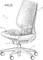
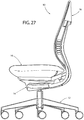
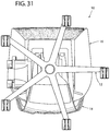
- a chair assembly embodiment is illustrated in a variety of views, including a perspective view ( Fig. 25 ), a front elevational view ( Fig. 26 ), a first side elevational view ( Fig. 27 ), a second side elevational view ( Fig. 28 ), a rear elevational view ( Fig. 29 ), a top plan view ( Fig. 30 ), and a bottom plan view ( Fig. 31 ).
Description
- The present invention relates to a chair assembly, and in particular to an office chair assembly comprising a back assembly including an upholstery arrangement that wraps about a front surface and a rear surface of the back assembly.
- The present invention is to provide a chair component that comprises a first chair member adapted to support a seated user, a second chair member movable between a first position, wherein the second chair component is substantially coplanar with the first chair member, and a second position, wherein the second chair member is substantially parallel with the first chair member, a cover member wrapped about at least a portion of the first chair member and at least a portion of the second chair member, and a single-piece drawstring operably coupled with the cover member to draw the cover member about the at least a portion of the first chair member and the at least a portion of the second chair member when the second chair member is in the first position, and wherein the cover member remains wrapped about the at least a portion of the first chair member and about the at least a portion of the second chair member as the second chair member is moved from the first position to the second position.
- An example that is not part of the present invention is to provide a method of assembling a chair component that comprises providing a first chair member adapted to support a seated user, providing a second chair member movable between a first position, wherein the second chair member is substantially coplanar with the first chair member, and a second position, wherein the second chair member is substantially parallel with the first chair member, and wrapping a cover member about at least a portion of the first chair member and at least a portion of the second chair member. The method further comprises providing a drawstring operably coupled with the cover member, drawing the cover member about the at least a portion of the first chair member and the at least a portion of the second chair member when the second chair member is in the first position, fixing an effective length of the drawstring while the second chair member is in the first position, moving the second chair member from the first position to the second position, and securing the second chair member in the second position.
- These and other features and advantages of the present invention will be further understood and appreciated by those skilled in the art by reference to the following specification, claims, and appended drawings.
-
-
Fig. 1 is a front perspective view of a chair assembly with a chair component embodying the present invention; -
Fig. 2 is a rear perspective view of the chair assembly; -
Fig. 3 is a side elevational view of the chair assembly showing the chair assembly in a lowered position and in a raised position in dashed line, and a seat assembly in a retracted position and an extended position in dashed line; -
Fig. 4 is a side elevational view of the chair assembly showing the chair assembly in an upright position and in a reclined position in dashed line; -
Fig. 5 is an exploded view of the seat assembly; -
Fig. 6 is an enlarged perspective view of the chair assembly with a portion of the seat assembly removed to illustrate a spring support assembly; -
Fig. 7 is a front perspective view of a back assembly; -
Fig. 8 is a side elevational view of the back assembly; -
Fig. 9A is an exploded front perspective view of the back assembly; -
Fig. 9B is an exploded rear perspective view of the back assembly; -
Fig. 10 is an enlarged perspective view of an area X,Fig. 9A ; -
Fig. 11 is an enlarged perspective view of an area XI,Fig. 2 ; -
Fig. 12 is a cross-sectional view of an upper back pivot assembly taken along the line XII-XII,Fig. 7 ; -
Fig. 13 is an enlarged perspective view of the area XIII,Fig. 9B ; -
Fig. 14 is a cross-sectional side view of a comfort member taken along the line XIV ―XIV,Fig. 13 ; -
Fig. 15A is an enlarged perspective view of the comfort member and a lumbar assembly; -
Fig. 15B is a rear perspective view of the comfort member and the lumbar assembly; -
Fig. 16A is a front perspective view of a pawl member; -
Fig. 16B is a rear perspective view of the pawl member; -
Fig. 17 is a partial cross-sectional perspective view along the line XVII-XVII,Fig. 15B ; -
Figs. 18A-18D are each exploded perspective views illustrating various steps of assembling a back support assembly, with a fixture shown in dotted line inFig. 18B , -
Fig. 19 is a perspective view of the area XIX,Fig. 9B ; -
Fig. 20A is a perspective view of the area XXA,Fig. 18A ; -
Fig. 20B is a perspective view of the area XXB,Fig. 18B ; -
Fig. 20C is an alternative embodiment to the embodiment shown inFig. 20A ; -
Figs. 21A-21H illustrate steps of securing a drawstring to the comfort member; -
Fig. 22 is a perspective view of the back assembly; -
Fig. 23 is a cross-sectional top view of the back assembly, taken along the line XXIII -XXIII,Fig. 22 ; -
Fig. 24 is a perspective view of the back support assembly with outer components removed to show interior components thereof; -
Fig. 25 is a perspective view of a chair assembly; -
Fig. 26 is a front elevational view of the chair assembly ofFig. 25 ; -
Fig. 27 is a first side elevational view of the chair assembly ofFig. 25 ; -
Fig. 28 is a second side elevational view of the chair assembly ofFig. 25 ; -
Fig. 29 is a rear elevational view of the chair assembly ofFig. 25 ; -
Fig. 30 is a top plan view of the chair assembly ofFig. 25 ; and -
Fig. 31 is a bottom plan view of the chair assembly ofFig. 25 . - For purposes of description herein, the terms "upper," "lower," "right," "left," "rear," "front," "vertical," "horizontal," and derivatives thereof shall relate to the invention as oriented in
Figs. 1 and 2 . However, it is to be understood that the invention may assume various alternative orientations and step sequences, except where expressly specified to the contrary. It is also to be understood that the specific devices and processes illustrated in the attached drawings, and described in the following specification are exemplary embodiments of the inventive concepts defined in the appended claims. Hence, specific dimensions and other physical characteristics relating to the embodiments disclosed herein are not to be considered as limiting, unless the claims expressly state otherwise. Various elements of the embodiments disclosed herein may be described as being operably coupled to one another, which includes elements either directly or indirectly coupled to one another. Further, the term "chair" as utilized herein encompasses various seating arrangements, including office chairs, vehicle seating, home seating, stadium seating, theater seating, and the like. - The reference numeral 10 (
Figs. 1 and 2 ) generally designates a chair assembly embodying the present invention. In the illustrated example, thechair assembly 10 includes acastered base assembly 12 abutting a supportingfloor surface 13, a control orsupport assembly 14 supported by thecastered base assembly 12, aseat assembly 16 and back assembly 18 each operably coupled with thecontrol assembly 14, and a pair ofarm assemblies 20. The control assembly 14 (Fig. 3 ) is operably coupled to thebase assembly 12 such that theseat assembly 16, theback assembly 18 and thearm assemblies 20 may be vertically adjusted between a fully lowered position A and a fully raised position B, and pivoted about avertical axis 21 in adirection 22. Theseat assembly 16 is operably coupled to thecontrol assembly 14 such that theseat assembly 16 is longitudinally adjustable with respect to thecontrol assembly 14 between a fully retracted position C and a fully extended position D. The seat assembly 16 (Fig. 4 ) and theback assembly 18 are operably coupled with thecontrol assembly 14 and with one another such that theback assembly 18 is movable between a fully upright position E and a fully reclined position F, and further such that theseat assembly 16 is movable between a fully upright position G and a fully reclined position H corresponding to the fully upright position E and the fully reclined position F of theback assembly 18, respectively. - The
base assembly 12 includes a plurality ofpedestal arms 24 radially extending and spaced about a hollowcentral column 26 that receives apneumatic cylinder 28 therein. Eachpedestal arm 24 is supported above thefloor surface 13 by an associatedcaster assembly 30. Although thebase assembly 12 is illustrated as including a multiple-arm pedestal assembly, it is noted that other suitable supporting structures may be utilized, including but not limited to fixed columns, multiple leg arrangements, vehicle seat support assemblies, and the like. - The seat assembly 16 (
Fig. 5 ) includes a relatively rigidseat support plate 32 having aforward edge 34, arearward edge 36, and a pair of C-shapedguide rails 38 defining the side edges of theseat support plate 32 and extending between theforward edge 34 and therearward edge 36. Theseat assembly 16 further includes a flexibly resilientouter seat shell 40 having a pair of upwardly turnedside portions 42 and an upwardly turnedrear portion 44 that cooperate to form an upwardly disposed generally concave shape. In the illustrated example, theseat shell 40 is comprised of a relatively flexible material such as a thermoplastic elastomer (TPE). In assembly, theouter seat shell 40 is secured and sandwiched between theseat support plate 32 and a plastic, flexiblyresilient seat pan 46 which is secured to theseat support plate 32 by a plurality of mechanical fasteners. Theseat pan 46 includes aforward edge 48, arearward edge 50, side edges 52 extending between theforward edge 48 and therearward edge 50, atop surface 54 and abottom surface 56 that cooperate to form an upwardly disposed generally concave shape. In the illustrated example, theseat pan 46 includes a plurality of longitudinally extendingslots 58 extending forwardly from therearward edge 50. Theslots 58 cooperate to define a plurality offingers 60 therebetween, eachfinger 60 being individually flexibly resilient. Theseat pan 46 further includes a plurality of laterally oriented,elongated apertures 62 located proximate theforward edge 48. Theapertures 62 cooperate to increase the overall flexibility of theseat pan 46 in the area thereof, and specifically allow aforward portion 64 of theseat pan 46 to flex in avertical direction 66 with respect to arearward portion 68 of theseat pan 46, as discussed further below. Theseat assembly 16 further includes afoam cushion member 70 that rests upon thetop surface 54 of theseat pan 46 and is cradled within theouter seat shell 40, afabric seat cover 72, and anupper surface 76 of thecushion members 70. A spring support assembly 78 (Figs. 5 and6 ) is secured to theseat assembly 16 and is adapted to flexibly support theforward portion 64 of theseat pan 46 for flexure in thevertical direction 66. In the illustrated example, thespring support assembly 78 includes asupport housing 80 comprising a foam and havingside portions 82 defining an upwardly concave arcuate shape. Thespring support assembly 78 further includes a relativelyrigid attachment member 84 that extends laterally between theside portions 82 of thesupport housing 80 and is located between thesupport housing 80 and theforward portion 64 of theseat pan 46. A plurality ofmechanical fasteners 86 secure thesupport housing 80 and theattachment member 84 to theforward portion 64 of theseat pan 46. Thespring support assembly 78 further includes a pair of cantilever springs 88 each having adistal end 90 received through a correspondingaperture 92 of theattachment member 84, and aproximate end 94 secured to theseat support plate 32 such that thedistal end 90 of eachcantilever spring 88 may flex in thevertical direction 66. A pair oflinear bearings 96 are fixedly attached to theattachment member 84 and aligned with theapertures 92 thereof, such that thelinear bearing 96 slidably receives the distal ends 90 of acorresponding cantilever spring 88. In operation, the cantilever springs 88 cooperate to allow theforward portion 64 of theseat pan 46, and more generally the entire forward portion ofseat assembly 16 to flex in thevertical direction 66 when a seated user rotates forward on theseat assembly 16 and exerts a downward force on the forward edge thereof. - The back assembly 18 (
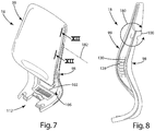
Figs. 7-9B ) includes aback frame assembly 98 and aback support assembly 99 supported thereby. Theback frame assembly 98 is generally comprised of a substantially rigid material such as metal, and includes a laterally extendingtop frame portion 100, a laterally extendingbottom frame portion 102, and a pair of curvedside frame portions 104 extending between thetop frame portion 100 and thebottom frame portion 102 and cooperating therewith to define anopening 106 having a relatively largeupper dimension 108 and a relatively narrowlower dimension 110. - The
back assembly 18 further includes a flexibly resilient,plastic back shell 112 that includes a forwardly-locatedfirst portion 119 having anupper portion 114 with an upper edge 121, alower portion 116, a pair of side edges 118 extending between theupper portion 114 and alower portion 116, a forwardly facingsurface 120 and a rearwardly facingsurface 122, wherein the width of theupper portion 114 is generally greater than the width of thelower portion 116, and thelower portion 116 is downwardly tapered to generally follow the rear elevational configuration of theframe assembly 98. Theback shell 112 further includes a rearwardly-locatedsecond portion 123 having anupper edge 125, alower edge 127 and a pair of side edges 129 extending between theupper edge 125 and thelower edge 127. Thesecond portion 123 is generally aligned with theupper portion 114 of thefirst portion 119 such that theupper edge 125 and the side edges 129 of thesecond portion 123 are generally aligned with the upper edge 121 and the side edges 118 of thefirst portion 119, respectively, as described below. - A
lower reinforcement member 115 attaches to hooks 117 (Fig. 9A ) oflower portion 116 of thefirst portion 119 of theback shell 112.Reinforcement member 115 includes a plurality ofprotrusions 113 that engagereinforcement ribs 134 to prevent side-to-side movement oflower reinforcement member 115 relative to theback shell 112. - The
first portion 119 of theback shell 112 also includes a plurality of integrally molded, forwardly and upwardly extending hooks 124 (Fig. 10 ) spaced about the periphery of theupper portion 114 thereof. An intermediate orlumbar portion 126 is located vertically between theupper portion 114 and thelower portion 116 of thefirst portion 119 of theback shell 112, and includes a plurality of laterally extendingslots 128 that cooperate to form a plurality of laterally extendingribs 130 located therebetween. Theslots 128 cooperate to provide additional flexure to theback shell 112 in the location thereof. Pairings oflateral ribs 130 are coupled by vertically extendingribs 132 integrally formed therewith and located at an approximate lateral midpoint thereof. Thevertical ribs 132 function to tie thelateral ribs 130 together and reduce vertical spreading therebetween as theback shell 112 is flexed at theintermediate portion 126 thereof when theback assembly 18 is moved from the upright position E to the reclined position F, as described further below. Thefirst portion 119 of theback shell 112 further includes a plurality of laterally-spacedreinforcement ribs 134 extending longitudinally along the vertical length of thefirst portion 119 between thelower portion 116 and theintermediate portion 126. It is noted that the depth of each of theribs 134 increases the further along each of theribs 134 from theintermediate portion 126, such that the overall rigidity of theback shell 112 increases along the length of the ribs from theintermediate portion 126 toward thelower portion 116. - The
first portion 119 of theback shell 112 further includes a pair of rearwardly extending, integrally moldedpivot bosses 138 forming part of an upperback pivot assembly 140. The back pivot assembly 140 (Figs. 11 and 12 ) includes thepivot bosses 138 of theback shell 112, a pair ofshroud members 142 that encompassrespective pivot bosses 138, arace member 144, and amechanical fastening assembly 146. Eachpivot boss 138 includes a pair ofside walls 148 and a rearwardly-facingconcave seating surface 150 having a vertically elongatedpivot slot 152 extending therethrough. Eachshroud member 142 is shaped so as to closely house thecorresponding pivot boss 138, and includes a plurality ofside walls 154 corresponding toside walls 148, and a rearwardly-facingconcave bearing surface 156 that includes a vertically elongated pivot slot extending therethrough, and which is adapted to align with theslot 152 of acorresponding pivot boss 138. Therace member 144 includes acenter portion 158 extending laterally along and abutting thetop frame portion 100 of theback frame assembly 98, and a pair of arcuately-shaped bearing surfaces 160 located at the ends thereof. Specifically, thecenter portion 158 includes afirst portion 162, and asecond portion 164, wherein thefirst portion 162 abuts a front surface of thetop frame portion 100 andsecond portion 164 abuts a top surface of thetop frame portion 100. Each bearingsurface 160 includes anaperture 166 extending therethrough. - In assembly, the
shroud members 142 are positioned about thecorresponding pivot bosses 138 of theback shell 112 and operably positioned between thefirst portion 119 of theback shell 112 andrace member 144 such that the bearingsurface 156 is sandwiched between theseating surface 150 of acorresponding pivot boss 138 and abearing surface 160. Themechanical fastening assemblies 146 each include abolt 172 that secures arounded abutment surface 174 of the bearingwasher 176 in sliding engagement with aninner surface 178 of thecorresponding pivot boss 138, and threadably engages acorresponding boss member 168 of theback frame assembly 98. In operation, the upperback pivot assembly 140 allows theback support assembly 99 to pivot with respect to the back frame assembly in a direction 180 (Fig. 8 ) about a pivot axis 182 (Fig. 7 ). - The back support assembly 99 (
Figs. 9A and 9B ) further includes a flexibly resilient comfort member 184 (Figs. 15A and 15B ) attached to theback shell 112 and slidably supporting alumbar assembly 186. Thecomfort member 184 includes anupper portion 188, alower portion 190, a pair ofside portions 192 having a plurality ofapertures 189 spaced therealong to increase the flexure thereof, aforward surface 193 and arearward surface 195, wherein theupper portion 188, thelower portion 190 and the side portions cooperate to form anaperture 194 that receives thelumbar assembly 186 therein. As best illustrated inFigs. 9B and13 , thecomfort member 184 includes a plurality of box-shapedcouplers 196 spaced about the periphery of theupper portion 188 and extending rearwardly from therearward surface 195. Each box-shapedcoupler 196 includes a pair ofside walls 198, atop wall 200 and arear wall 204 that cooperate to form an interior space 202. In assembly, the comfort member 184 (Figs. 12-14 ) is secured to theback shell 112 by aligning and vertically inserting thehooks 124 of theback shell 112 into the interior space 202 of each of the box-shapedcouplers 196. Thecomfort member 184 further includes a plurality of upholstery alignment andconnection pads 199 extending rearwardly from therearward surface 195 and spaced about the outer periphery of thecomfort member 184. As best illustrated inFig. 14 , the thickness t of thecomfort member 184 in the region of thepads 199 is greater than the thickness tʹ of thecomfort member 184 in other regions of thecomfort member 184. In the illustrated example, the majority of the area of thecomfort member 184 comprises the thickness tʹ. Thepads 199 function to increase the structural rigidity of thecomfort member 184 in the areas of the upholstery arrangement is attached thereto, as well as to provide alignment features for properly aligning the upholstery arrangement with respect to thecomfort member 184 during assembly, as described below. - The comfort member 184 (
Figs. 15A and 15B ) includes an integrally molded, longitudinally extendingsleeve 206 extending rearwardly from therearward surface 195 and having a rectangularly-shaped cross-sectional configuration. Thelumbar assembly 186 includes a forwardly laterally concave and forwardly vertically convex, flexiblyresilient body portion 208, and anintegral support portion 210 extending upwardly from thebody portion 208. In the illustrated example, thebody portion 208 is shaped such that thebody portion 208 vertically tapers along the height thereof so as to generally follow the contours and shape of theaperture 194 of thecomfort member 184. Thesupport portion 210 is slidably received within thesleeve 206 of thecomfort member 184 such that thelumbar assembly 186 is vertically adjustable with respect to the remainder of theback support assembly 99 between a fully lowered position I and a fully raised position J.A pawl member 212 selectively engages a plurality ofapertures 214 spaced along the length ofsupport portion 210, thereby releasably securing thelumbar assembly 186 at selected vertical positions between the fully lowered position I and the fully raised position J. The pawl member 212 (Figs. 16A and 16B ) includes ahousing portion 216 havingengagement tabs 218 located at the ends thereof and rearwardly offset from anouter surface 220 of thehousing portion 216. A flexiblyresilient finger 222 is centrally disposed within thehousing portion 216 and includes a rearwardly-extendingpawl 224. - In assembly, the pawl member 212 (
Fig. 17 ) is positioned within anaperture 226 located within theupper portion 188 of thecomfort member 184 such that theouter surface 220 of thehousing portion 216 of thepawl member 212 is coplanar with theforward surface 193 of thecomfort member 184, and such that theengagement tabs 218 of thehousing portion 216 abut therearward surface 195 of thecomfort member 184. Thesupport portion 210 of thelumbar assembly 186 is then positioned within thesleeve 206 of thecomfort member 184 such that thesleeve 206 is slidable therein and thepawl 224 is selectively engageable with theapertures 214, thereby allowing the user to optimize the position of thelumbar assembly 186 with respect to the overallback support assembly 99. Specifically, thebody portion 208 of thelumbar assembly 186 includes a pair of outwardly extending integral handle portions 251 (Fig. 18D ) each having a C-shaped cross-sectional configuration that wraps about and guides along therespective side edge 192 of theback shell 112. - In operation, a user adjusts the relative vertical position of the
lumbar assembly 186 with respect to theback shell 112 by grasping one or both of thehandle portions 251 and sliding thehandle assembly 251 along theback shell 184 in a vertical direction. Astop tab 228 is integrally formed within adistal end 230 and is offset therefrom so as to engage an end wall of thesleeve 206 of thecomfort member 184, thereby limiting the vertical downward travel of thesupport portion 210 of thelumbar assembly 186 with respect to thesleeve 206 of thecomfort member 184. - The back support assembly 99 (
Figs. 9A and 9B ) also includes acushion member 252 having anupper portion 254 and alower portion 256, wherein thelower portion 256 tapers along the vertical length thereof to correspond to the overall shape and taper of theback shell 112 and thecomfort member 184, and atopper cushion 253 comprising a relatively thin foam material. - The back support assembly 99 (
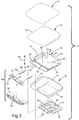
Fig. 18A ) further includes an upholstery arrangement or coverassembly 300 that houses theback shell 112, thelumbar support assembly 186, thecushion member 252 and atopper cushion 253 therein. In the illustrated example, thecover assembly 300 comprises a fabric material that may be elastically deformable in one or more directions. Thecover assembly 300 includes afront side 302 and arear side 304 that are sewn together along the respective side edges thereof to form afirst pocket 306 having a first interior orinner space 308 that receives thecomfort member 184, thecushion member 252 and thetopper cushion 253 therein, and aflap portion 310 that is sewn to therear side 304 and cooperates therewith to form asecond pocket 348 having a second interior orinner space 350 that receives thelumbar support assembly 186 therein. It is noted that thecushion member 252, thecomfort member 184 and thesecond portion 123 of theback shell 112 are assembled with thetopper cushion 253 prior to assembly with thecover assembly 300, and specifically are attached to a rear surface of thetopper cushion 253 via an adhesive. - In assembly, the
first pocket 306 is formed by attaching the respective side edges of thefront side 302 and therear side 304 to one another such as by sewing or other means suitable for the material for which thecover assembly 300 is comprised, and to define the firstinterior space 308. An edge of theflap portion 310 is then secured to therear side 304 proximate amidsection 312 thereof. In the illustrated example, thecomfort member 184 and thesecond portion 123 of theback shell 112 are placed within a fixture 301 (Fig. 18B ) that holds thesecond portion 123 in a planar relationship to thecomfort member 184. The combination of thesecond portion 123 of theback shell 164, thecomfort member 184 and the cushion member 296 are then inserted into theinterior space 308 of thefirst pocket 306 via anaperture 314 located on the rear side 304 (Fig. 18B ). Theupholstery cover assembly 300 is stretched about thecushion member 252, thesecond portion 123 of theback shell 112 and thecomfort member 184, and is secured to thecomfort member 184 by a plurality ofapertures 320 that receive upwardly extending hook members 324 (Fig. 19 ) therethrough. Alternatively, thecover assembly 300 may be configured such thatapertures 320 are positioned to also receive T-shapedattachment members 322 therethrough. In the illustrated example, theattachment members 322 and thehook members 324 are integrally formed with thecomfort member 184. Eachattachment member 322 is provided with a T-shaped cross-section or boat-cleat configuration having afirst portion 328 extending perpendicularly rearward from within arecess 329 of therear surface 256 of thecomfort member 184, and a pair ofsecond portions 330 located at a distal end of thefirst portion 328 and extending outwardly therefrom in opposite relation to one another. One of thesecond portions 330 cooperates with thefirst portion 328 to form anangled engagement surface 332. Therecess 329 defines anedge 334 about the perimeter thereof. - The
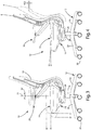
cover assembly 300 is further secured to thecomfort member 184 by a single,continuous drawstring 336 that extends through adrawstring tunnel 338 of thecover assembly 300, which is captured within multiple attachment features of thesecond portion 123 of theback shell 112 and thecomfort member 184 and is in turn secured to theattachment members 322. Specifically, thedrawstring 336 anddrawstring tunnel 338 are aligned with and secured to the plurality of upholstery alignment and connection pads 199' (Fig. 20A ) similar to the pads 199 (Fig. 20B ) of thecomfort member 184 via a plurality of staples (not shown). Alternatively, thedrawstring 336 anddrawstring tunnel 338 are routed about hook members 313 (Fig. 20C ) located near the corners between thebottom edge 127 andside edges 129 of thesecond portion 123 of theback shell 112, and are captured by a plurality ofcouplers 315 each including a plurality of elastically resilient, interspacedteeth 317 and spaced about the periphery of thesecond portion 123. Thedrawstring 336 anddrawstring tunnel 338 are then aligned with thepads 199 of thesecond portion 123 to assure proper alignment of thecover assembly 300 with theback shell 112 and the overallback support assembly 99. In the illustrated example, thedrawstring 336 anddrawstring tunnel 338 are secured to the second portion via a plurality ofstaples 319 which are inserted into thethicker pads 199. - As best illustrated in
Figs. 21A - 21H , thedrawstring 336 is drawn taut and each free end of thedrawstring 336 is then secured to an associatedattachment member 322 in a knot-free manner and without the use of a mechanical fastener that is separate from thecomfort member 184, thereby fixing the effective length of thedrawstring 336 through the remainder of the assembly process. Thedrawstring 336 is wrapped about the associatedattachment member 322 such that the tension in thedrawstring 336 about theattachment member 322 forces thedrawstring 336 against theengagement surface 332 that angles towards therecess 329, thereby forcing a portion of thedrawstring 336 into therecess 329 and into engagement with at least a portion of theedge 334 of therecess 329 resulting in an increased frictional engagement between thedrawstring 336 and thecomfort member 184. Thelumbar assembly 186 is then aligned with the assembly of thecover assembly 300, thecushion member 252 and thecomfort member 184 such that thebody portion 272 of thelumbar assembly 186 is located near themidsection 312 of thecover assembly 300, and thesupport portion 210 of thelumbar assembly 186 is coupled with thecomfort member 184 as described above. Theflap portion 310 is then folded over thelumbar assembly 186, thereby creating the additional pocket 348 (Fig. 18D ) having theinterior space 350. A distally locatededge 352 of theflap portion 310 is attached to thecomfort member 184 by a plurality ofapertures 354 with theflap portion 310 that receive thehooks 324 therethrough. Thedistal edge 352 may also be sewn to therear side 304 of thecover assembly 300. In the illustrated example, the side edges 356 of theflap portion 310 are not attached to the remainder of thecover assembly 300, such that the side edges 356 cooperate with the remainder of thecover assembly 300 to formslots 360 through thehandle portions 251 of thelumbar assembly 186. Thesecond pocket 348 is configured such that thelumbar assembly 186 is vertically adjustable therein. - The assembly of the
cover assembly 300, thecushion member 252, thecomfort member 184, thelumbar assembly 186 and thesecond portion 123 of theback shell 112 are then attached to thefirst portion 119 of theback shell 112. Specifically, thecomfort member 184 and thesecond portion 123 of theback shell 112 are removed from the associated fixture (301), and thecomfort member 184 is then attached to the first portion of the back shell via thehooks 124 and box-shapedcouplers 196 as previously described. Thesecond portion 123 of theback shell 112 is then rotated about thefirst portion 119 of theback shell 112 from a position where thesecond portion 123 is generally planar with thefirst portion 119, as shown inFig. 18D , to a position where thesecond portion 123 is wrapped about thefirst portion 119 and is generally parallel therewith, as shown inFig. 8 . As best illustrated inFigs. 11 and20A , thesecond portion 123 includes a plurality of rearwardly-extending T-shapedcouplers 321, while the first portion includes a plurality of cooperatingslots 323 that releasably receive thecouplers 321 therein, thereby securing thesecond portion 123 in the second position. Proper alignment of thesecond portion 123 with thefirst portion 119 is provided via generally conically-shaped locators 351 (Fig. 20A ) extending forwardly from thesecond portion 123 that locate and align with corresponding conically-shaped recesses 355 (Fig. 24 ) extending into the rear surface of thefirst portion 119 of theback shell 112. - As best illustrated in
Figs. 22 and 23 , theback assembly 18 is further configured to increase the comfort of the outer edges of theback support assembly 99 and improve the aesthetics thereof. Specifically, the flexiblyresilient comfort member 184 includes a recessedpocket 400 that receives thecushion member 252 therein, such that the outer edge of thecushion member 252 is spaced inwardly from the outer edge of thecomfort member 184, thereby providing an aesthetically clean appearance to the outer peripheral edge of the overallback support assembly 99. - As noted above, the back assembly 18 (
Fig. 4 ) is reclinable between an upright position E and a reclined position F. During recline, agap 402 opens between thetop frame portion 100 of theframe assembly 98 and thelower edge 127 of thesecond portion 123 of theback shell 112, as a result of flexure of theback support assembly 99 and pivoting of theback support assembly 99 about thepivot axis 182 in thedirection 180. In the illustrated example, a shield member 406 (Figs. 12 and24 ) prevents access to thegap 402, thereby reducing or eliminating a potential pinch-point for the user. Theshield member 406 includes abody portion 408 secured to a rear surface of thefirst portion 119 of theback shell 112 by a plurality ofscrews 410 received within rearwardly-extendingbosses 412 of theshield member 406. Theshield member 406 further includes an arcuately-shaped, downwardlyconcave engagement portion 414 that slidably tracks along thehorizontal portion 100 of theframe assembly 98 and thecenter portion 158 of therace member 144 as theback assembly 18 is reclined and the back support assembly is flexed. - A chair assembly embodiment is illustrated in a variety of views, including a perspective view (
Fig. 25 ), a front elevational view (Fig. 26 ), a first side elevational view (Fig. 27 ), a second side elevational view (Fig. 28 ), a rear elevational view (Fig. 29 ), a top plan view (Fig. 30 ), and a bottom plan view (Fig. 31 ). - In the foregoing description, it will be readily appreciated by those skilled in the art that alternative combinations of the various components and elements of the invention and modifications to the invention may be made without departing from the concepts of the original invention when the concept is disclosed, such as applying the inventive concepts as disclosed herein to vehicle seating, stadium seating, home seating, theater seating and the like. Such modifications are to be within the scope of the appended claims.
Claims (15)
- A chair component (18), comprising:a first chair member (119) adapted to support a seated user;a second chair member (123)movable between a first position, wherein the second chair member (123) is substantially coplanar with the first chair member (119), and a second position, wherein the second chair member (123) is substantially parallel with the first chair member (119);a cover member (300) wrapped about at least a portion of the first chair member (119) and at least a portion of the second chair member (123); anda single-piece drawstring (336) operably coupled with the cover member (300) to draw the cover member (300) about the at least a portion of the first chair member (119) and the at least a portion of the second chair member (123) when the second chair member (123) is in the first position, and wherein the cover member (300) remains wrapped about the at least a portion of the first chair member (119) and about the at least a portion of the second chair member (123) as the second chair member (123) is moved from the first position to the second position.
- The chair component of claim 1, wherein the drawstring (336) abuts the first chair member (119).
- The chair component of any one of the preceding claims, wherein the drawstring (336) is secured to the first chair member (119) by at least one fastener (319) that is separate from the first chair member (119).
- The chair component of claim 3, wherein the at least one fastener (319) comprises at least one staple (319).
- The chair component of either of claims 3 and 4, wherein the first chair member (119) includes a front surface (193), a rear surface (195), and at least one raised portion (199) extending rearwardly from the rear surface (195), and wherein the at least one fastener (319) is received within the at least one raised portion (199).
- The chair component of claim 5, wherein the front surface (193) of the first chair member (119) and the rear surface (195) of the first chair member (119) define a first thickness (t') therebetween, and wherein the front surface (193) of the of the first chair member (119) and the at least one raised portion (199) define a second thickness (t) therebetween that is greater than the first thickness (t').
- The chair component of any one of the preceding claims, wherein the first chair member (119) includes a front surface (193), a rear surface (195), and at least one raised portion (199) extending rearwardly from the rear surface (195), wherein the cover member (300) is aligned with the at least one raised portion (199).
- The chair component of any one of the preceding claims, wherein the first chair member (119) includes at least one first coupler (323) and the second chair member (123) includes at least one second coupler (321) that engages the first coupler (323), thereby securing the second chair member (123) to the first chair member (119) when the second chair member (123) is in the second position.
- The chair component of claim 8, wherein the at least one first coupler (323) and the at least one second coupler (321) comprise a quick-connect fastener.
- The chair component of any one of the preceding claims, wherein the cover member (300) includes a fabric portion (302, 304, 312) and a drawstring tunnel (338) located proximate an edge of the fabric portion (302, 304, 312), wherein the drawstring (336) is received within the drawstring tunnel (338).
- The chair component of claim 10, wherein the drawstring tunnel (338) and the drawstring (336) are secured to a rear surface (195) of the first chair member (119) by at least one fastener (319).
- The chair component of either of claims 10 and 11, wherein the fabric is elastically deformable in at least one direction.
- The chair component of any one of the preceding claims, wherein the second chair member (123) is spaced from the first chair member (119) when the second chair member (123) is in the first position, and wherein the second chair member (123) contacts the first chair member (119) when the second chair member (123) is in the second position.
- The chair component of any one of the preceding claims, further comprising:a back frame assembly (98);a back support assembly (99) including the first and second chair members (119, 123) and operably coupled to the back frame assembly (98) and adapted to support a seated user, wherein the back support assembly (99) is movable between a first position with respect to the back frame assembly (98) and a second position with respect to the back frame assembly (98) that is different than the first position, the back frame assembly (98) and the back support assembly (99) cooperating to define a gap (402) therebetween, the gap (402) defining a first distance when the back support assembly (99) is in the first position and a second distance that is greater than the first distance when the back support assembly (99) is in the second position; anda shield member (406) substantially filling the gap (402) to reduce access thereto as the back support assembly (99) is moved between the first and second positions.
- The chair component of claim 14, wherein the shield member (406) slidably tracks along a select one of the back frame assembly (98) and the back support assembly (99) as the back support assembly (99) is moved between the first and second positions.
Priority Applications (1)
| Application Number | Priority Date | Filing Date | Title |
|---|---|---|---|
| EP21186616.5A EP3915440A1 (en) | 2012-09-20 | 2013-09-19 | Chair assembly |
Applications Claiming Priority (11)
| Application Number | Priority Date | Filing Date | Title |
|---|---|---|---|
| US201261703666P | 2012-09-20 | 2012-09-20 | |
| US201261703661P | 2012-09-20 | 2012-09-20 | |
| US201261703667P | 2012-09-20 | 2012-09-20 | |
| US201261703659P | 2012-09-20 | 2012-09-20 | |
| US201261703677P | 2012-09-20 | 2012-09-20 | |
| US201261703515P | 2012-09-20 | 2012-09-20 | |
| US201261703663P | 2012-09-20 | 2012-09-20 | |
| US201261733661P | 2012-12-05 | 2012-12-05 | |
| US201361754803P | 2013-01-21 | 2013-01-21 | |
| US14/029,273 US9167910B2 (en) | 2012-09-20 | 2013-09-17 | Chair assembly |
| PCT/US2013/060644 WO2014047304A2 (en) | 2012-09-20 | 2013-09-19 | Chair assembly |
Related Child Applications (2)
| Application Number | Title | Priority Date | Filing Date |
|---|---|---|---|
| EP21186616.5A Division EP3915440A1 (en) | 2012-09-20 | 2013-09-19 | Chair assembly |
| EP21186616.5A Division-Into EP3915440A1 (en) | 2012-09-20 | 2013-09-19 | Chair assembly |
Publications (3)
| Publication Number | Publication Date |
|---|---|
| EP2897498A2 EP2897498A2 (en) | 2015-07-29 |
| EP2897498A4 EP2897498A4 (en) | 2016-06-15 |
| EP2897498B1 true EP2897498B1 (en) | 2021-08-25 |
Family
ID=50273703
Family Applications (2)
| Application Number | Title | Priority Date | Filing Date |
|---|---|---|---|
| EP21186616.5A Pending EP3915440A1 (en) | 2012-09-20 | 2013-09-19 | Chair assembly |
| EP13838698.2A Active EP2897498B1 (en) | 2012-09-20 | 2013-09-19 | Chair assembly |
Family Applications Before (1)
| Application Number | Title | Priority Date | Filing Date |
|---|---|---|---|
| EP21186616.5A Pending EP3915440A1 (en) | 2012-09-20 | 2013-09-19 | Chair assembly |
Country Status (8)
| Country | Link |
|---|---|
| US (5) | US9167910B2 (en) |
| EP (2) | EP3915440A1 (en) |
| JP (2) | JP6328641B2 (en) |
| CN (1) | CN104640481B (en) |
| AU (2) | AU2013318040B2 (en) |
| CA (3) | CA2974799C (en) |
| HK (1) | HK1205442A1 (en) |
| WO (1) | WO2014047304A2 (en) |
Families Citing this family (31)
| Publication number | Priority date | Publication date | Assignee | Title |
|---|---|---|---|---|
| DE102011104972B4 (en) | 2011-06-08 | 2015-03-05 | Haworth, Inc. | Seating furniture, in particular office chair |
| US11304528B2 (en) * | 2012-09-20 | 2022-04-19 | Steelcase Inc. | Chair assembly with upholstery covering |
| US9167910B2 (en) * | 2012-09-20 | 2015-10-27 | Steelcase Inc. | Chair assembly |
| USD697726S1 (en) * | 2012-09-20 | 2014-01-21 | Steelcase Inc. | Chair |
| USD697729S1 (en) * | 2012-09-20 | 2014-01-21 | Steelcase Inc. | Chair |
| US8998339B2 (en) * | 2012-09-20 | 2015-04-07 | Steelcase Inc. | Chair assembly with upholstery covering |
| US9480339B2 (en) * | 2012-12-31 | 2016-11-01 | Sava Cvek | Seat with pelvic support |
| EP2956334A1 (en) * | 2013-02-18 | 2015-12-23 | Faurecia Automotive Seating, LLC | Seat back for vehicle seat |
| US9565949B2 (en) * | 2014-05-30 | 2017-02-14 | Steelcase Inc. | Chair upholstery attachment arrangement and method |
| JP6627444B2 (en) * | 2015-11-13 | 2020-01-08 | コクヨ株式会社 | Chair |
| DE102016102556A1 (en) * | 2016-02-15 | 2017-08-17 | Interstuhl Büromöbel GmbH & Co. KG | Backrest for an office chair |
| US10463153B2 (en) * | 2016-06-09 | 2019-11-05 | Steelcase Inc. | Seating arrangement |
| US10219627B2 (en) * | 2016-09-29 | 2019-03-05 | Steelcase Inc. | Compliant seating structure |
| USD859045S1 (en) * | 2016-10-24 | 2019-09-10 | Sitland S.P.A. | Chair base |
| US10299602B2 (en) * | 2017-03-22 | 2019-05-28 | Yao-Chuan Wu | Chair |
| US10473136B2 (en) * | 2017-05-25 | 2019-11-12 | Ford Global Technologies, Llc | Vehicle seating cushion with snap-fit fasteners to interconnect with snap-fit receivers on a structural support |
| US10426269B1 (en) | 2018-04-30 | 2019-10-01 | Buzz Seating, Inc. | Chair with appendage accommodations |
| US11357329B2 (en) * | 2019-12-13 | 2022-06-14 | Steelcase Inc. | Body support assembly and methods for the use and assembly thereof |
| US11690457B2 (en) * | 2020-02-04 | 2023-07-04 | Hni Technologies Inc. | Chair with flexible internal support |
| USD936985S1 (en) | 2020-02-19 | 2021-11-30 | Steelcase Inc. | Chair |
| USD937595S1 (en) | 2020-02-19 | 2021-12-07 | Steelcase Inc. | Chair |
| USD961317S1 (en) | 2020-02-19 | 2022-08-23 | Steelcase Inc. | Backrest |
| USD935824S1 (en) | 2020-02-19 | 2021-11-16 | Steelcase Inc. | Seat |
| USD961280S1 (en) | 2020-02-19 | 2022-08-23 | Steelcase Inc. | Chair |
| USD937024S1 (en) | 2020-02-19 | 2021-11-30 | Steelcase Inc. | Backrest |
| USD936984S1 (en) | 2020-02-19 | 2021-11-30 | Steelcase Inc. | Chair |
| USD961281S1 (en) * | 2020-02-19 | 2022-08-23 | Steelcase Inc. | Chair |
| US20230055017A1 (en) * | 2021-08-23 | 2023-02-23 | Lippert Components, Inc. | Devices and method to removably secure a seatback shell to a seatback frame |
| US11890998B2 (en) * | 2021-09-30 | 2024-02-06 | Lear Corporation | Seat trim panel |
| US11800932B1 (en) | 2022-04-12 | 2023-10-31 | Series International, Llc | Chair with molded panel |
| US11464337B1 (en) * | 2022-04-12 | 2022-10-11 | Series International, Llc | Chair with molded panel |
Citations (1)
| Publication number | Priority date | Publication date | Assignee | Title |
|---|---|---|---|---|
| US6220661B1 (en) * | 1999-04-19 | 2001-04-24 | Steelcase Development Inc. | Chair back and method of assembly |
Family Cites Families (101)
| Publication number | Priority date | Publication date | Assignee | Title |
|---|---|---|---|---|
| US1782815A (en) | 1928-11-12 | 1930-11-25 | Wil Fry Corp | Seat cover |
| US2258119A (en) | 1938-03-01 | 1941-10-07 | Juan G Mathe | Adjustable seat structure for motor vehicles and the like |
| US2361370A (en) | 1940-03-04 | 1944-10-31 | Prec Metal Workers | Cushion seat |
| US2394969A (en) | 1945-12-20 | 1946-02-12 | Robinson Louis | Combination couch and bed |
| US2661051A (en) | 1948-12-20 | 1953-12-01 | Charles E Mccormick | Trim fastening means for vehicle seats |
| US2673600A (en) | 1951-04-12 | 1954-03-30 | Cramer Posture Chair Co Inc | Molding for chair backs or the like |
| US2786513A (en) | 1954-06-30 | 1957-03-26 | American Seating Co | Church pew |
| US2946374A (en) | 1957-09-30 | 1960-07-26 | Curtiss Wright Corp | Seat construction and the like |
| US3174797A (en) | 1963-09-30 | 1965-03-23 | Massey Ferguson Ltd | Replaceable upholstery for furniture |
| US3223450A (en) | 1964-11-23 | 1965-12-14 | Charles R Pollock | Upholstered furniture |
| US3215468A (en) | 1965-03-01 | 1965-11-02 | Milsco Mfg Co | Seat for material handling vehicles |
| US3695707A (en) | 1970-11-19 | 1972-10-03 | American Seating Co | Recliner vehicle seat |
| US3669499A (en) | 1970-12-30 | 1972-06-13 | Steelcase Inc | Chair |
| US3797887A (en) | 1971-06-28 | 1974-03-19 | American Seating Co | Seat for urban mass transit vehicles |
| US3722950A (en) | 1971-12-03 | 1973-03-27 | Blair Mfg Co | Chair with replaceable upholstery cover |
| US3874731A (en) | 1973-05-04 | 1975-04-01 | Ford Motor Co | Injection molded seating |
| US4157203A (en) | 1977-05-09 | 1979-06-05 | Center For Design Research And Development N.V. | Articulated double back for chairs |
| US4106739A (en) | 1977-05-19 | 1978-08-15 | Gasser George E | Bumper edge member for chairs |
| US4333683A (en) | 1978-12-04 | 1982-06-08 | Center For Design Research And Development N.V. | Chair with automatically adjustable tilting back |
| US4385783A (en) | 1979-05-11 | 1983-05-31 | Knoll International, Inc. | Upholstered furniture element |
| US4420186A (en) | 1979-07-02 | 1983-12-13 | Hans Kaufeld Gmbh & Co. | Convertible low-back, high-back upholstered furniture |
| DE3004585A1 (en) | 1980-02-08 | 1981-08-13 | Wilkhahn Wilkening + Hahne GmbH + Co, 3252 Bad Münder | SEAT FURNITURE WITH UPHOLSTERY ATTACHED TO A CARRIER |
| US4580836A (en) | 1982-12-23 | 1986-04-08 | Intercollection Development S.A. Gyrenmoos | Chair |
| US4597605A (en) | 1984-11-05 | 1986-07-01 | Gilbert Robert W | Combined tote bag and seat cushion |
| DE3604534A1 (en) | 1986-02-13 | 1987-08-20 | Hartmut Lohmeyer | SEAT FURNITURE WITH A SEAT AND A BACKREST RESILIENTLY ELASTICALLY |
| US4744600A (en) | 1986-05-06 | 1988-05-17 | Itoki Co., Ltd. | Cushioning mechanism for use with seat of chair and interlocking cushioning mechanism for seat and backrest |
| US4711491A (en) | 1986-06-09 | 1987-12-08 | Jonathan Ginat | Swivel tilt mechanism for chair |
| DE3629883A1 (en) | 1986-09-02 | 1988-03-10 | Girsberger Holding Ag | Cushion fastening |
| ATE65675T1 (en) | 1987-07-24 | 1991-08-15 | Equus Marketing Ag | CHAIR, ESPECIALLY AN OFFICE OR WORK CHAIR. |
| US4772070A (en) | 1987-12-03 | 1988-09-20 | Leto Jr James | Contoured seat covering for automotive vehicle bench seat |
| FR2624845B1 (en) | 1987-12-29 | 1994-04-08 | Tachi S Co Ltd | VEHICLE SEAT WITH SEPARATE MATTRESSES |
| US4875734A (en) | 1987-12-30 | 1989-10-24 | Tachi-S Co., Ltd. | Automotive seat |
| US4773707A (en) | 1988-03-28 | 1988-09-27 | Vadala Peter S | Headrest attachment |
| US4836609A (en) | 1988-04-18 | 1989-06-06 | Milsco Manufacturing Company | Vehicle seat |
| JP2592108B2 (en) | 1988-08-31 | 1997-03-19 | コクヨ株式会社 | Chair with backrest |
| US4869552A (en) | 1988-09-14 | 1989-09-26 | Shelby Williams Industries, Inc. | Flexible backrest assembly for a chair |
| US5015034A (en) | 1988-11-25 | 1991-05-14 | Prince Corporation | Upholstery system |
| DE4107451C2 (en) | 1991-03-08 | 2003-04-10 | Dauphin Friedrich W Gmbh | Backrest for a chair |
| JPH0817730B2 (en) | 1991-05-21 | 1996-02-28 | 株式会社イトーキ | Shell structure in chair with back and seat synchronized movement |
| US5297851A (en) | 1991-12-05 | 1994-03-29 | Westinghouse Electric Corp. | Chair fastening device |
| US5288136A (en) | 1992-02-14 | 1994-02-22 | Herman Miller, Inc. | Chair membrane fastener |
| US5265292A (en) | 1993-03-08 | 1993-11-30 | Pauline Green | Foldable lounge cushion |
| US5338092A (en) | 1993-03-19 | 1994-08-16 | Lear Seating Corporation | Drawstring seat cover |
| US5630643A (en) | 1993-06-01 | 1997-05-20 | Steelcase Inc | Upholstered chair with two-piece shell |
| US5716096A (en) | 1993-09-20 | 1998-02-10 | Lear Corporation | Drawstring seat cover for attachment to a seat |
| US5529373A (en) | 1994-06-27 | 1996-06-25 | Hon Industries Inc. | Apparatus and method for covering a chair form with fabric |
| DE4427754C2 (en) | 1994-08-05 | 1997-09-11 | Mauser Office Gmbh | Chair, especially swivel chair |
| DK172786B1 (en) | 1995-05-02 | 1999-07-19 | Haag As | Furniture with two adjacent swivel supports |
| US5527097A (en) | 1995-06-02 | 1996-06-18 | Miami Metal Products, Inc. | Edging member and seating device therefore |
| US5704691A (en) | 1996-06-06 | 1998-01-06 | Hon Industries Inc. | Padded chair construction |
| JP3325783B2 (en) | 1996-10-09 | 2002-09-17 | センター フォア デザイン リサーチ アンド ディベロプメント ナームローゼフェンノートチャップ | Adjustable chair |
| US5845967A (en) | 1996-10-25 | 1998-12-08 | Fisher Price Inc. | Booster seat |
| US5746477A (en) | 1997-02-03 | 1998-05-05 | O'sullivan Industries, Inc. | Upholstery to furniture fastener system |
| US5836647A (en) | 1997-05-20 | 1998-11-17 | Turman; Ben | Vehicle seat with shock absorption |
| US6199900B1 (en) | 1997-06-09 | 2001-03-13 | Gary D. Zeigler | Vehicle safety collision headrest system |
| US5951110A (en) | 1997-10-17 | 1999-09-14 | Irwin Seating Company | Contoured plastic seat back |
| US5871258A (en) | 1997-10-24 | 1999-02-16 | Steelcase Inc. | Chair with novel seat construction |
| DE29802360U1 (en) | 1998-02-12 | 1999-06-10 | Vogtherr Burkhard | Functional chair |
| JP3884186B2 (en) | 1998-07-09 | 2007-02-21 | 株式会社岡村製作所 | Chair |
| US6027164A (en) | 1998-12-18 | 2000-02-22 | Daimlerchrysler Corporation | Combination seat and armrest with storage compartments |
| DE29921499U1 (en) | 1999-12-07 | 2001-04-12 | Johnson Controls Gmbh | Device for covering a gap between a backrest and a lower seat part of a vehicle seat |
| AUPQ597500A0 (en) | 2000-03-02 | 2000-03-23 | Camatic Pty. Limited | Improved theatre chair |
| US6499801B1 (en) | 2000-03-03 | 2002-12-31 | Steelcase Development Corporation | Chair having removable cover and cushion |
| CA2310349A1 (en) | 2000-05-22 | 2001-11-22 | Todd D. Krupiczewicz | Office chair |
| US6540950B1 (en) | 2000-09-20 | 2003-04-01 | Dahti, Inc. | Carrier and attachment method for load bearing fabric |
| AU783829B2 (en) | 2000-09-28 | 2005-12-08 | Formway Furniture Limited | A reclinable chair |
| JP4497701B2 (en) | 2000-10-26 | 2010-07-07 | コクヨ株式会社 | Drawing member storage structure and chair to which the drawing member storage structure is applied |
| US6739663B2 (en) | 2001-02-23 | 2004-05-25 | Krueger International, Inc. | Flexible bar-type back pivot mounting arrangement for a chair |
| US6616228B2 (en) | 2001-06-20 | 2003-09-09 | Steelcase Development Corporation | Compliant back for seating unit |
| JP4255670B2 (en) | 2002-10-16 | 2009-04-15 | タカノ株式会社 | Terminal positioning structure of chair upholstery |
| US7055911B2 (en) | 2003-05-08 | 2006-06-06 | Haworth, Inc. | Mesh chair |
| US6726278B1 (en) | 2003-06-13 | 2004-04-27 | First Source Furniture Group Llc | Back pad for chair back |
| JP4250128B2 (en) | 2003-09-29 | 2009-04-08 | 株式会社豊田中央研究所 | Sheet |
| US7073693B2 (en) * | 2003-10-16 | 2006-07-11 | Intier Automotive Inc. | Drawstringing kit |
| JP4620950B2 (en) * | 2003-12-05 | 2011-01-26 | 株式会社岡村製作所 | Chair backrest seat structure and method for manufacturing the same |
| JP4642346B2 (en) | 2003-12-10 | 2011-03-02 | 株式会社内田洋行 | Chair upholstery structure |
| US6896327B1 (en) | 2004-03-30 | 2005-05-24 | Daniel Paul Chairs, Llc | Flexible back mechanism for stackable chairs |
| CN2754460Y (en) * | 2004-12-15 | 2006-02-01 | 易晶有限公司 | Back frame of computer chair |
| US7837260B2 (en) | 2005-05-31 | 2010-11-23 | Milsco Manufacturing Company | Vehicle seat assembly system |
| US7419212B2 (en) | 2005-10-27 | 2008-09-02 | Haygood David L | Protective strips for use in the manufacture of upholstered furniture |
| US7490392B2 (en) | 2005-12-07 | 2009-02-17 | Steelcase Inc. | Seating unit with formed cushion, and manufacturing method |
| US20070200407A1 (en) | 2006-02-27 | 2007-08-30 | Eberlein David C | Seating unit with adjustable components |
| US7530640B2 (en) * | 2006-04-07 | 2009-05-12 | L & P Property Management Company | Layered chair back and chair seat |
| WO2008094865A1 (en) | 2007-01-29 | 2008-08-07 | Herman Miller, Inc. | Seating structure and methods for the use thereof |
| JP4824610B2 (en) | 2007-03-19 | 2011-11-30 | テイ・エス テック株式会社 | Outdoor vehicle seat |
| US7604298B2 (en) * | 2007-06-01 | 2009-10-20 | Steelcase Development Corporation | Chair back attachment and method of assembly |
| US7828387B2 (en) | 2007-12-28 | 2010-11-09 | Tachi-S Co., Ltd. | Seat back structure of upside-recessed-and-headrest-storage type of seat |
| US8939508B2 (en) | 2008-05-13 | 2015-01-27 | Chokchai Charoenapornwatana | Chairs with flexible spring backrest |
| US20090322129A1 (en) | 2008-06-26 | 2009-12-31 | Rodill James W | Multi-function lounge chair cover for folding lounge chairs |
| US8328279B2 (en) | 2009-01-12 | 2012-12-11 | Faurecia Automotive Seating, Llc | Vehicle seat pad |
| US8011732B2 (en) | 2009-04-15 | 2011-09-06 | Honda Motor Co., Ltd. | Tiltable anti-pinch seat assembly and pinch guard |
| US8152235B2 (en) | 2009-05-13 | 2012-04-10 | Michigan Tube Swagers & Fabricators, Inc. | Method of upholstering chair element |
| JP5375432B2 (en) * | 2009-08-21 | 2013-12-25 | トヨタ紡織株式会社 | Vehicle seat cover structure |
| US8029066B2 (en) | 2009-09-28 | 2011-10-04 | Tung-Hua Su | Backrest assembly |
| CN102781284B (en) | 2010-02-10 | 2015-09-09 | 株式会社冈村制作所 | The tensioning of chair tensioning material arranges structure |
| JP5636250B2 (en) | 2010-10-12 | 2014-12-03 | タカノ株式会社 | Locking structure of tension fabric and locking method of tension fabric |
| JP5685077B2 (en) | 2010-12-27 | 2015-03-18 | 株式会社イトーキ | Chair and seat or back constituting it |
| JP5676240B2 (en) | 2010-12-27 | 2015-02-25 | 株式会社イトーキ | Chair body pressure support |
| JP5671333B2 (en) | 2010-12-27 | 2015-02-18 | 株式会社イトーキ | Chair |
| US8733834B2 (en) * | 2011-04-29 | 2014-05-27 | Lear Corporation | Trim assembly |
| US9167910B2 (en) * | 2012-09-20 | 2015-10-27 | Steelcase Inc. | Chair assembly |
-
2013
- 2013-09-17 US US14/029,273 patent/US9167910B2/en active Active
- 2013-09-17 US US14/029,284 patent/US8973990B2/en active Active
- 2013-09-19 CA CA2974799A patent/CA2974799C/en active Active
- 2013-09-19 EP EP21186616.5A patent/EP3915440A1/en active Pending
- 2013-09-19 JP JP2015533188A patent/JP6328641B2/en active Active
- 2013-09-19 AU AU2013318040A patent/AU2013318040B2/en active Active
- 2013-09-19 EP EP13838698.2A patent/EP2897498B1/en active Active
- 2013-09-19 CA CA2881698A patent/CA2881698C/en active Active
- 2013-09-19 CN CN201380048755.2A patent/CN104640481B/en active Active
- 2013-09-19 WO PCT/US2013/060644 patent/WO2014047304A2/en active Application Filing
- 2013-09-19 CA CA3004560A patent/CA3004560A1/en not_active Abandoned
-
2015
- 2015-04-03 US US14/678,065 patent/US9706853B2/en active Active
- 2015-06-09 HK HK15105488.1A patent/HK1205442A1/en unknown
-
2017
- 2017-01-31 AU AU2017200624A patent/AU2017200624A1/en not_active Abandoned
- 2017-06-12 US US15/619,591 patent/US9986848B2/en active Active
-
2018
- 2018-04-17 JP JP2018078954A patent/JP2018126579A/en active Pending
- 2018-05-03 US US15/970,422 patent/US10413083B2/en active Active
Patent Citations (1)
| Publication number | Priority date | Publication date | Assignee | Title |
|---|---|---|---|---|
| US6220661B1 (en) * | 1999-04-19 | 2001-04-24 | Steelcase Development Inc. | Chair back and method of assembly |
Also Published As
| Publication number | Publication date |
|---|---|
| CA2881698A1 (en) | 2014-03-27 |
| US20150208820A1 (en) | 2015-07-30 |
| CA2974799A1 (en) | 2014-03-27 |
| US20180249845A1 (en) | 2018-09-06 |
| CN104640481A (en) | 2015-05-20 |
| EP3915440A1 (en) | 2021-12-01 |
| HK1205442A1 (en) | 2015-12-18 |
| CA2881698C (en) | 2017-10-03 |
| US9167910B2 (en) | 2015-10-27 |
| US9986848B2 (en) | 2018-06-05 |
| AU2013318040B2 (en) | 2016-11-03 |
| EP2897498A2 (en) | 2015-07-29 |
| US20140077541A1 (en) | 2014-03-20 |
| US8973990B2 (en) | 2015-03-10 |
| WO2014047304A2 (en) | 2014-03-27 |
| AU2017200624A1 (en) | 2017-02-16 |
| CA3004560A1 (en) | 2014-03-27 |
| CN104640481B (en) | 2017-12-01 |
| US20170280888A1 (en) | 2017-10-05 |
| AU2013318040A1 (en) | 2015-02-19 |
| JP2018126579A (en) | 2018-08-16 |
| JP2015529146A (en) | 2015-10-05 |
| US9706853B2 (en) | 2017-07-18 |
| US10413083B2 (en) | 2019-09-17 |
| EP2897498A4 (en) | 2016-06-15 |
| WO2014047304A3 (en) | 2014-12-31 |
| JP6328641B2 (en) | 2018-05-23 |
| US20140077543A1 (en) | 2014-03-20 |
| CA2974799C (en) | 2018-12-04 |
Similar Documents
| Publication | Publication Date | Title |
|---|---|---|
| EP2897498B1 (en) | Chair assembly | |
| US11464341B2 (en) | Chair assembly with upholstery covering | |
| US6079785A (en) | Chair having adjustable lumbar support | |
| US20140077540A1 (en) | Chair Assembly | |
| US11147379B2 (en) | Cushion for folding chair | |
| US11229294B2 (en) | Chair assembly with upholstery covering | |
| JP2020049114A (en) | Chair |
Legal Events
| Date | Code | Title | Description |
|---|---|---|---|
| PUAI | Public reference made under article 153(3) epc to a published international application that has entered the european phase |
Free format text: ORIGINAL CODE: 0009012 |
|
| 17P | Request for examination filed |
Effective date: 20150416 |
|
| AK | Designated contracting states |
Kind code of ref document: A2 Designated state(s): AL AT BE BG CH CY CZ DE DK EE ES FI FR GB GR HR HU IE IS IT LI LT LU LV MC MK MT NL NO PL PT RO RS SE SI SK SM TR |
|
| AX | Request for extension of the european patent |
Extension state: BA ME |
|
| DAX | Request for extension of the european patent (deleted) | ||
| REG | Reference to a national code |
Ref country code: DE Ref legal event code: R079 Ref document number: 602013078990 Country of ref document: DE Free format text: PREVIOUS MAIN CLASS: A47C0031110000 Ipc: A47C0007020000 |
|
| A4 | Supplementary search report drawn up and despatched |
Effective date: 20160518 |
|
| RIC1 | Information provided on ipc code assigned before grant |
Ipc: A47C 7/02 20060101AFI20160511BHEP |
|
| STAA | Information on the status of an ep patent application or granted ep patent |
Free format text: STATUS: EXAMINATION IS IN PROGRESS |
|
| 17Q | First examination report despatched |
Effective date: 20200203 |
|
| STAA | Information on the status of an ep patent application or granted ep patent |
Free format text: STATUS: EXAMINATION IS IN PROGRESS |
|
| GRAP | Despatch of communication of intention to grant a patent |
Free format text: ORIGINAL CODE: EPIDOSNIGR1 |
|
| STAA | Information on the status of an ep patent application or granted ep patent |
Free format text: STATUS: GRANT OF PATENT IS INTENDED |
|
| RIN1 | Information on inventor provided before grant (corrected) |
Inventor name: KRUPICZEWICZ, TODD D. Inventor name: HALL, JEFFREY A. Inventor name: GROENDAL, DALE M. Inventor name: PETERSON, GORDON J. |
|
| INTG | Intention to grant announced |
Effective date: 20210310 |
|
| GRAS | Grant fee paid |
Free format text: ORIGINAL CODE: EPIDOSNIGR3 |
|
| GRAA | (expected) grant |
Free format text: ORIGINAL CODE: 0009210 |
|
| STAA | Information on the status of an ep patent application or granted ep patent |
Free format text: STATUS: THE PATENT HAS BEEN GRANTED |
|
| AK | Designated contracting states |
Kind code of ref document: B1 Designated state(s): AL AT BE BG CH CY CZ DE DK EE ES FI FR GB GR HR HU IE IS IT LI LT LU LV MC MK MT NL NO PL PT RO RS SE SI SK SM TR |
|
| REG | Reference to a national code |
Ref country code: GB Ref legal event code: FG4D |
|
| REG | Reference to a national code |
Ref country code: CH Ref legal event code: EP |
|
| REG | Reference to a national code |
Ref country code: DE Ref legal event code: R096 Ref document number: 602013078990 Country of ref document: DE |
|
| REG | Reference to a national code |
Ref country code: IE Ref legal event code: FG4D Ref country code: AT Ref legal event code: REF Ref document number: 1422907 Country of ref document: AT Kind code of ref document: T Effective date: 20210915 |
|
| REG | Reference to a national code |
Ref country code: LT Ref legal event code: MG9D |
|
| REG | Reference to a national code |
Ref country code: NL Ref legal event code: MP Effective date: 20210825 |
|
| REG | Reference to a national code |
Ref country code: AT Ref legal event code: MK05 Ref document number: 1422907 Country of ref document: AT Kind code of ref document: T Effective date: 20210825 |
|
| PG25 | Lapsed in a contracting state [announced via postgrant information from national office to epo] |
Ref country code: HR Free format text: LAPSE BECAUSE OF FAILURE TO SUBMIT A TRANSLATION OF THE DESCRIPTION OR TO PAY THE FEE WITHIN THE PRESCRIBED TIME-LIMIT Effective date: 20210825 Ref country code: SE Free format text: LAPSE BECAUSE OF FAILURE TO SUBMIT A TRANSLATION OF THE DESCRIPTION OR TO PAY THE FEE WITHIN THE PRESCRIBED TIME-LIMIT Effective date: 20210825 Ref country code: RS Free format text: LAPSE BECAUSE OF FAILURE TO SUBMIT A TRANSLATION OF THE DESCRIPTION OR TO PAY THE FEE WITHIN THE PRESCRIBED TIME-LIMIT Effective date: 20210825 Ref country code: ES Free format text: LAPSE BECAUSE OF FAILURE TO SUBMIT A TRANSLATION OF THE DESCRIPTION OR TO PAY THE FEE WITHIN THE PRESCRIBED TIME-LIMIT Effective date: 20210825 Ref country code: FI Free format text: LAPSE BECAUSE OF FAILURE TO SUBMIT A TRANSLATION OF THE DESCRIPTION OR TO PAY THE FEE WITHIN THE PRESCRIBED TIME-LIMIT Effective date: 20210825 Ref country code: NO Free format text: LAPSE BECAUSE OF FAILURE TO SUBMIT A TRANSLATION OF THE DESCRIPTION OR TO PAY THE FEE WITHIN THE PRESCRIBED TIME-LIMIT Effective date: 20211125 Ref country code: PT Free format text: LAPSE BECAUSE OF FAILURE TO SUBMIT A TRANSLATION OF THE DESCRIPTION OR TO PAY THE FEE WITHIN THE PRESCRIBED TIME-LIMIT Effective date: 20211227 Ref country code: LT Free format text: LAPSE BECAUSE OF FAILURE TO SUBMIT A TRANSLATION OF THE DESCRIPTION OR TO PAY THE FEE WITHIN THE PRESCRIBED TIME-LIMIT Effective date: 20210825 Ref country code: AT Free format text: LAPSE BECAUSE OF FAILURE TO SUBMIT A TRANSLATION OF THE DESCRIPTION OR TO PAY THE FEE WITHIN THE PRESCRIBED TIME-LIMIT Effective date: 20210825 Ref country code: BG Free format text: LAPSE BECAUSE OF FAILURE TO SUBMIT A TRANSLATION OF THE DESCRIPTION OR TO PAY THE FEE WITHIN THE PRESCRIBED TIME-LIMIT Effective date: 20211125 |
|
| PG25 | Lapsed in a contracting state [announced via postgrant information from national office to epo] |
Ref country code: PL Free format text: LAPSE BECAUSE OF FAILURE TO SUBMIT A TRANSLATION OF THE DESCRIPTION OR TO PAY THE FEE WITHIN THE PRESCRIBED TIME-LIMIT Effective date: 20210825 Ref country code: LV Free format text: LAPSE BECAUSE OF FAILURE TO SUBMIT A TRANSLATION OF THE DESCRIPTION OR TO PAY THE FEE WITHIN THE PRESCRIBED TIME-LIMIT Effective date: 20210825 Ref country code: GR Free format text: LAPSE BECAUSE OF FAILURE TO SUBMIT A TRANSLATION OF THE DESCRIPTION OR TO PAY THE FEE WITHIN THE PRESCRIBED TIME-LIMIT Effective date: 20211126 |
|
| PG25 | Lapsed in a contracting state [announced via postgrant information from national office to epo] |
Ref country code: NL Free format text: LAPSE BECAUSE OF FAILURE TO SUBMIT A TRANSLATION OF THE DESCRIPTION OR TO PAY THE FEE WITHIN THE PRESCRIBED TIME-LIMIT Effective date: 20210825 |
|
| PG25 | Lapsed in a contracting state [announced via postgrant information from national office to epo] |
Ref country code: DK Free format text: LAPSE BECAUSE OF FAILURE TO SUBMIT A TRANSLATION OF THE DESCRIPTION OR TO PAY THE FEE WITHIN THE PRESCRIBED TIME-LIMIT Effective date: 20210825 |
|
| REG | Reference to a national code |
Ref country code: CH Ref legal event code: PL |
|
| REG | Reference to a national code |
Ref country code: BE Ref legal event code: MM Effective date: 20210930 |
|
| REG | Reference to a national code |
Ref country code: DE Ref legal event code: R097 Ref document number: 602013078990 Country of ref document: DE |
|
| PG25 | Lapsed in a contracting state [announced via postgrant information from national office to epo] |
Ref country code: SM Free format text: LAPSE BECAUSE OF FAILURE TO SUBMIT A TRANSLATION OF THE DESCRIPTION OR TO PAY THE FEE WITHIN THE PRESCRIBED TIME-LIMIT Effective date: 20210825 Ref country code: SK Free format text: LAPSE BECAUSE OF FAILURE TO SUBMIT A TRANSLATION OF THE DESCRIPTION OR TO PAY THE FEE WITHIN THE PRESCRIBED TIME-LIMIT Effective date: 20210825 Ref country code: RO Free format text: LAPSE BECAUSE OF FAILURE TO SUBMIT A TRANSLATION OF THE DESCRIPTION OR TO PAY THE FEE WITHIN THE PRESCRIBED TIME-LIMIT Effective date: 20210825 Ref country code: MC Free format text: LAPSE BECAUSE OF FAILURE TO SUBMIT A TRANSLATION OF THE DESCRIPTION OR TO PAY THE FEE WITHIN THE PRESCRIBED TIME-LIMIT Effective date: 20210825 Ref country code: EE Free format text: LAPSE BECAUSE OF FAILURE TO SUBMIT A TRANSLATION OF THE DESCRIPTION OR TO PAY THE FEE WITHIN THE PRESCRIBED TIME-LIMIT Effective date: 20210825 Ref country code: CZ Free format text: LAPSE BECAUSE OF FAILURE TO SUBMIT A TRANSLATION OF THE DESCRIPTION OR TO PAY THE FEE WITHIN THE PRESCRIBED TIME-LIMIT Effective date: 20210825 Ref country code: AL Free format text: LAPSE BECAUSE OF FAILURE TO SUBMIT A TRANSLATION OF THE DESCRIPTION OR TO PAY THE FEE WITHIN THE PRESCRIBED TIME-LIMIT Effective date: 20210825 |
|
| PLBE | No opposition filed within time limit |
Free format text: ORIGINAL CODE: 0009261 |
|
| STAA | Information on the status of an ep patent application or granted ep patent |
Free format text: STATUS: NO OPPOSITION FILED WITHIN TIME LIMIT |
|
| PG25 | Lapsed in a contracting state [announced via postgrant information from national office to epo] |
Ref country code: LU Free format text: LAPSE BECAUSE OF NON-PAYMENT OF DUE FEES Effective date: 20210919 Ref country code: IT Free format text: LAPSE BECAUSE OF FAILURE TO SUBMIT A TRANSLATION OF THE DESCRIPTION OR TO PAY THE FEE WITHIN THE PRESCRIBED TIME-LIMIT Effective date: 20210825 Ref country code: IE Free format text: LAPSE BECAUSE OF NON-PAYMENT OF DUE FEES Effective date: 20210919 Ref country code: BE Free format text: LAPSE BECAUSE OF NON-PAYMENT OF DUE FEES Effective date: 20210930 |
|
| 26N | No opposition filed |
Effective date: 20220527 |
|
| PG25 | Lapsed in a contracting state [announced via postgrant information from national office to epo] |
Ref country code: SI Free format text: LAPSE BECAUSE OF FAILURE TO SUBMIT A TRANSLATION OF THE DESCRIPTION OR TO PAY THE FEE WITHIN THE PRESCRIBED TIME-LIMIT Effective date: 20210825 Ref country code: LI Free format text: LAPSE BECAUSE OF NON-PAYMENT OF DUE FEES Effective date: 20210930 Ref country code: CH Free format text: LAPSE BECAUSE OF NON-PAYMENT OF DUE FEES Effective date: 20210930 |
|
| PG25 | Lapsed in a contracting state [announced via postgrant information from national office to epo] |
Ref country code: HU Free format text: LAPSE BECAUSE OF FAILURE TO SUBMIT A TRANSLATION OF THE DESCRIPTION OR TO PAY THE FEE WITHIN THE PRESCRIBED TIME-LIMIT; INVALID AB INITIO Effective date: 20130919 |
|
| PG25 | Lapsed in a contracting state [announced via postgrant information from national office to epo] |
Ref country code: CY Free format text: LAPSE BECAUSE OF FAILURE TO SUBMIT A TRANSLATION OF THE DESCRIPTION OR TO PAY THE FEE WITHIN THE PRESCRIBED TIME-LIMIT Effective date: 20210825 |
|
| PGFP | Annual fee paid to national office [announced via postgrant information from national office to epo] |
Ref country code: GB Payment date: 20230927 Year of fee payment: 11 |
|
| PGFP | Annual fee paid to national office [announced via postgrant information from national office to epo] |
Ref country code: FR Payment date: 20230925 Year of fee payment: 11 Ref country code: DE Payment date: 20230927 Year of fee payment: 11 |