EP2897438A1 - Routing an IP session over WLAN - Google Patents
Routing an IP session over WLAN Download PDFInfo
- Publication number
- EP2897438A1 EP2897438A1 EP14151786.2A EP14151786A EP2897438A1 EP 2897438 A1 EP2897438 A1 EP 2897438A1 EP 14151786 A EP14151786 A EP 14151786A EP 2897438 A1 EP2897438 A1 EP 2897438A1
- Authority
- EP
- European Patent Office
- Prior art keywords
- bearer
- session
- identifier
- radio device
- wlan
- Prior art date
- Legal status (The legal status is an assumption and is not a legal conclusion. Google has not performed a legal analysis and makes no representation as to the accuracy of the status listed.)
- Ceased
Links
Images


Classifications
-
- H—ELECTRICITY
- H04—ELECTRIC COMMUNICATION TECHNIQUE
- H04W—WIRELESS COMMUNICATION NETWORKS
- H04W40/00—Communication routing or communication path finding
- H04W40/02—Communication route or path selection, e.g. power-based or shortest path routing
-
- H—ELECTRICITY
- H04—ELECTRIC COMMUNICATION TECHNIQUE
- H04L—TRANSMISSION OF DIGITAL INFORMATION, e.g. TELEGRAPHIC COMMUNICATION
- H04L61/00—Network arrangements, protocols or services for addressing or naming
- H04L61/09—Mapping addresses
- H04L61/10—Mapping addresses of different types
- H04L61/106—Mapping addresses of different types across networks, e.g. mapping telephone numbers to data network addresses
-
- H—ELECTRICITY
- H04—ELECTRIC COMMUNICATION TECHNIQUE
- H04L—TRANSMISSION OF DIGITAL INFORMATION, e.g. TELEGRAPHIC COMMUNICATION
- H04L45/00—Routing or path finding of packets in data switching networks
- H04L45/74—Address processing for routing
-
- H—ELECTRICITY
- H04—ELECTRIC COMMUNICATION TECHNIQUE
- H04L—TRANSMISSION OF DIGITAL INFORMATION, e.g. TELEGRAPHIC COMMUNICATION
- H04L69/00—Network arrangements, protocols or services independent of the application payload and not provided for in the other groups of this subclass
- H04L69/30—Definitions, standards or architectural aspects of layered protocol stacks
- H04L69/32—Architecture of open systems interconnection [OSI] 7-layer type protocol stacks, e.g. the interfaces between the data link level and the physical level
- H04L69/322—Intralayer communication protocols among peer entities or protocol data unit [PDU] definitions
- H04L69/327—Intralayer communication protocols among peer entities or protocol data unit [PDU] definitions in the session layer [OSI layer 5]
-
- H—ELECTRICITY
- H04—ELECTRIC COMMUNICATION TECHNIQUE
- H04W—WIRELESS COMMUNICATION NETWORKS
- H04W76/00—Connection management
- H04W76/10—Connection setup
- H04W76/12—Setup of transport tunnels
-
- H—ELECTRICITY
- H04—ELECTRIC COMMUNICATION TECHNIQUE
- H04W—WIRELESS COMMUNICATION NETWORKS
- H04W8/00—Network data management
- H04W8/26—Network addressing or numbering for mobility support
-
- H—ELECTRICITY
- H04—ELECTRIC COMMUNICATION TECHNIQUE
- H04L—TRANSMISSION OF DIGITAL INFORMATION, e.g. TELEGRAPHIC COMMUNICATION
- H04L2101/00—Indexing scheme associated with group H04L61/00
- H04L2101/60—Types of network addresses
- H04L2101/618—Details of network addresses
- H04L2101/622—Layer-2 addresses, e.g. medium access control [MAC] addresses
-
- H—ELECTRICITY
- H04—ELECTRIC COMMUNICATION TECHNIQUE
- H04L—TRANSMISSION OF DIGITAL INFORMATION, e.g. TELEGRAPHIC COMMUNICATION
- H04L61/00—Network arrangements, protocols or services for addressing or naming
- H04L61/50—Address allocation
- H04L61/5038—Address allocation for local use, e.g. in LAN or USB networks, or in a controller area network [CAN]
-
- H—ELECTRICITY
- H04—ELECTRIC COMMUNICATION TECHNIQUE
- H04W—WIRELESS COMMUNICATION NETWORKS
- H04W76/00—Connection management
- H04W76/10—Connection setup
- H04W76/11—Allocation or use of connection identifiers
-
- H—ELECTRICITY
- H04—ELECTRIC COMMUNICATION TECHNIQUE
- H04W—WIRELESS COMMUNICATION NETWORKS
- H04W76/00—Connection management
- H04W76/10—Connection setup
- H04W76/15—Setup of multiple wireless link connections
-
- H—ELECTRICITY
- H04—ELECTRIC COMMUNICATION TECHNIQUE
- H04W—WIRELESS COMMUNICATION NETWORKS
- H04W84/00—Network topologies
- H04W84/02—Hierarchically pre-organised networks, e.g. paging networks, cellular networks, WLAN [Wireless Local Area Network] or WLL [Wireless Local Loop]
- H04W84/10—Small scale networks; Flat hierarchical networks
- H04W84/12—WLAN [Wireless Local Area Networks]
Definitions
- the present disclosure relates to methods and devices for routing an internet protocol (IP) session of a telecommunication standard over a wireless local area network (WLAN) radio access network (RAN).
- IP internet protocol
- WLAN wireless local area network
- RAN radio access network
- the third generation partnership project (3GPP) defines the concept of bearers.
- a bearer uniquely identifies traffic flows that receive a common quality of service (QoS) between a user equipment (UE) and a packet data network (PDN) gateway (PGW).
- QoS quality of service
- UE user equipment
- PGW packet data network gateway
- the currently standardized bearer mechanism is using bearers in the General Packet Radio Service (GPRS) tunnelling protocol (GTP) interface between the Trusted WLAN Access Network (TWAN) gateway (TWAG) and PGW but between UE and the TWAN there is only one pipe.
- GTP General Packet Radio Service
- TWAN Trusted WLAN Access Network
- PGW Packet Radio Service gateway
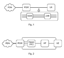
- FIG. 1 is a schematic block diagram illustrating evolved packet core (EPC and evolved packet system (EPS) concepts, which are also defined in the 3GPP technical specifications (TS) 23.401 and 23.402. The figure explains the bearer concept over a 3GPP radio interface.
- each PDN connection contains at least one bearer. That bearer is called default bearer. Additional bearers within that same PDN connection are called dedicated bearers.
- the PDN is an IP network such as the Internet or an intranet e.g. a service network.
- the PGW is a functional node providing access for one or more UE to one or more PDNs.
- the PDN connection provides a UE with an access channel to a PDN. It is a logical tunnel between UE and PGW.
- Each PDN connection has a single IP address or prefix.
- a UE can set up multiple PDN connections, possibly to the same Access Point Name (APN), a string containing the name of the PDN.
- the PDN connection between the PGW and the UE is further illustrated as containing a plurality of EPS bearers (three in figure 1 ).
- Each EPS bearer is defined by a set of IP flows with the same QoS profile.
- Each EPS bearer runs end-to-end (e2e) between the UE and the PGW but is a concatenation of an S5 GTP tunnel between the PGW and a serving gateway (SGW), an S1 GTP tunnel between the SGW and an evolved Node B (eNB), and a radio bearer between the eNB and the UE.
- SGW serving gateway
- eNB evolved Node B
- the PGW communicates via the S2a interface between the PGW and a TWAG, comprising or being associated with an access controller (AC).
- a PDN connection contains one or more S2a bearers (three in figure 2 , between the PGW and the TWAG).
- S2a supports the bearer concept in that each bearer is a GTP tunnel. Also here there is a PDN connection between the UE and the PGW.
- WLAN does not support the bearer concept.
- each PDN connection is a logical concatenation of one or more S2a tunnels between the PGW and the TWAG and a single L2 point-to-point link between the TWAG and the UE.
- MAC virtual media access control
- the functional architecture is shown in figures 3 and 4 , where figure 3 illustrates the functional S2a based architecture in a non-roaming scenario and figure 4 illustrates the functional split of the TWAN, and where figure 4 zooms in what is denoted as the Trusted WLAN Access Network (TWAN) in figure 3 .
- TWAN Trusted WLAN Access Network
- 3GPP Rel-12 allows a UE to setup multiple PDN connections over WLAN. Each PDN connection is identified by a (virtual) MAC address of the TWAG.
- a bearer identity is defined for identification of each of the bearers between the TWAG and the UE. Without this identity the TWAN will have to classify the uplink traffic and send it on the correct bearer on the S2a interface.
- a method performed by a network element in a communication network for routing an IP session to a radio device over a WLAN, the IP session comprising at least one bearer.
- the method comprises obtaining an identifier for each of the at least one bearer of the IP session.
- the method also comprises mapping downlink data packets of the IP session to the identifier for each of the at least one bearer of the IP session.
- the method also comprises transmitting each of the DL packets on a bearer of said at least one bearer, together with the identifier for the bearer it has been mapped to, over the WLAN to the radio device.
- a computer program product comprising computer-executable components for causing a network element to perform an embodiment of a method of the present disclosure when the computer-executable components are run on processor circuitry comprised in the network element.
- a network element for a communication network for routing an IP session to a radio device over a WLAN, the IP session comprising at least one bearer.
- the network element comprises processor circuitry, and a storage unit storing instructions that, when executed by the processor circuitry, cause the network element to obtain an identifier for each of the at least one bearer of the IP session.
- the instructions also cause the network element to map downlink (DL) data packets of the IP session to the identifier for each of the at least one bearer of the IP session.
- the instructions also cause the network element to transmit each of the DL packets on a bearer of said at least one bearer, together with the identifier for the bearer it has been mapped to, over the WLAN to the radio device.
- the method comprises obtaining an identifier for each of the at least one bearer of the IP session.
- the method also comprises mapping uplink (UL) data packets of the IP session to the identifier for each of the at least one bearer of the IP session.
- the method also comprises transmitting each of the UL packets on a bearer of said at least one bearer, together with the identifier for the bearer it has been mapped to, over the WLAN.
- a computer program product comprising computer-executable components for causing a radio device to perform an embodiment of a method of the present disclosure when the computer-executable components are run on processor circuitry comprised in the radio device.
- a radio device for a communication network for routing an IP session over a WLAN, the IP session comprising at least one bearer.
- the radio device comprises processor circuitry, and a storage unit storing instructions that, when executed by the processor circuitry, cause the radio device to obtain an identifier for each of the at least one bearer of the IP session.
- the instructions also cause the radio device to map UL data packets of the IP session to the identifier for each of the at least one bearer of the IP session.
- the instructions also cause the radio device to transmit each of the UL packets on a bearer of said at least one bearer, together with the identifier for the bearer it has been mapped to, over the WLAN.
- a method performed by a network element in a communication network for routing an IP session from a radio device over a WLAN, the IP session comprising at least one bearer.
- the method comprises obtaining an identifier for each of the at least one bearer of the IP session.
- the method also comprises mapping UL data packets of the IP session to the at least one bearer based on the identifier for each of the at least one bearer.
- the method also comprises transmitting each of the UL packets on the bearer which it has been mapped to.
- a network element for a communication network for routing an IP session from a radio device over a WLAN, the IP session comprising at least one bearer.
- the network element comprises processor circuitry, and a storage unit storing instructions that, when executed by the processor circuitry, cause the network element to obtain an identifier for each of the at least one bearer of the IP session.
- the instructions also cause the network element to map UL data packets of the IP session to the at least one bearer based on the identifier for each of the at least one bearer.
- the instructions also cause the network element to transmit each of the UL packets on the bearer which it has been mapped to.
- the bearer concept can be applied also over WLAN in accordance with the present disclosure. For instance, instead of assigning a virtual MAC address per PDN connection, each bearer gets assigned a virtual MAC address.
- the concept of bearers as they are implemented in 3GPP networks can be extended to cover also the link between the radio device, e.g. UE, and TWAN.
- MAC addresses e.g. virtual MAC-addresses (vMAC) are used as the way of distinguishing between different bearers over the WELAN interface.
- vMAC virtual MAC-addresses
- the vMAC is assigned by a new non-access stratum (NAS) protocol Wireless LAN Control Protocol (WLCP) to be defined by 3GPP.
- NAS non-access stratum
- WLCP Wireless LAN Control Protocol
- a dedicated virtual MAC address can be assigned per bearer.
- Embodiments of the present disclosure using vMAC as bearer identifier allows for one-to-one mapping to the bearers without changing the underlying transport over WLAN between the radio device and the network element, e.g. TWAG. If a new identifier would have been used, it would be necessary to add that to the already standardized frame format between the radio device and the TWAG.
- the use of vMAC is only an example of an identifier for each bearer, other examples including real MAC addresses and VLAN IDs. Also, embodiments of the present disclosure may be relevant also for other IP sessions than a PDN connection.
- TFT Traffic Flow Template
- FIG. 5 is a schematic block diagram of an embodiment of a communication network 1 in accordance with the present disclosure.
- a PDN 2 is in communication in an IP session with a radio device 6 over a WLAN 7.
- three bearers 8, e.g. EPS bearers are set up between a PGW 3 and the radio device 6, via a network element (NW element) 4, e.g. a TWAG, and an access point (AP) 5 of the WLAN 7.
- NW element network element
- AP access point
- the bearers 8 are thus set up e2e between the PGW 3 and the radio device 6 and the TWAG need not route all data packages over a single pipe over the WLAN RAN.
- FIG. 6 is schematic block diagram of an embodiment of a network element 4 in accordance with the present disclosure.
- the NW element 4, or a part thereof may e.g. be or be part of a TWAG or an AC, or at least partly be or be part of a node separate from the TWAG or AC.
- the NW element 4 comprises processor circuitry 61 e.g. a central processing unit (CPU).
- the processor circuitry 61 may comprise one or a plurality of processing units in the form of microprocessor(s).
- ASIC application specific integrated circuit
- FPGA field programmable gate array
- CPLD complex programmable logic device
- the processor circuitry 61 is configured to run one or several computer program(s) or software 81 (see also figure 8 ) stored in a storage 62 of one or several storage unit(s) e.g. a memory.
- the storage unit is regarded as a computer readable means 82 (see figure 8 ) as discussed herein and may e.g. be in the form of a Random Access Memory (RAM), a Flash memory or other solid state memory, or a hard disk, or be a combination thereof.
- the processor circuitry 61 is also configured to store data in the storage 62, as needed.
- the NW element 4 also comprises a communication interface 63, e.g. comprising a transmitter and a receiver which may be combined to form a transceiver or be present as distinct units.
- the communication interface 63 is configured to cooperate with the processor circuitry 61 to transform data bits to be transmitted to a suitable signal.
- the communication interface 63 is configured to cooperate with the processor circuitry 61 to transform a received signal to data bits.
- FIG. 7 is a schematic block diagram of an embodiment of a radio device 6 in accordance with the present disclosure.
- the radio device 6 may be any device or user equipment (UE), mobile or stationary, enabled to communicate over a radio cannel in a communications network 1, for instance but not limited to e.g. mobile phone, smart phone, modem, sensors, meters, vehicles (e.g. a car), household appliances, medical appliances, media players, cameras, or any type of consumer electronic, for instance but not limited to television, radio, lighting arrangements, tablet computer, laptop, or personal computer (PC).
- the radio device 6 comprises processor circuitry 71 e.g. a central processing unit (CPU).
- the processor circuitry 71 may comprise one or a plurality of processing units in the form of microprocessor(s).
- the processor circuitry 71 is configured to run one or several computer program(s) or software 81 (see also figure 8 ) stored in a storage 72 of one or several storage unit(s) e.g. a memory.
- the storage unit is regarded as a computer readable means 82 (see figure 8 ) as discussed herein and may e.g. be in the form of a Random Access Memory (RAM), a Flash memory or other solid state memory, or a hard disk, or be a combination thereof.
- RAM Random Access Memory
- Flash memory or other solid state memory
- hard disk or be a combination thereof.
- the processor circuitry 71 is also configured to store data in the storage 72, as needed.
- the radio device 6 also comprises a radio communication interface 73, e.g. comprising a receiver, a transmitter and an antenna, which may be combined to form a transceiver or be present as distinct units.
- the radio interface 73 is configured to cooperate with the processor circuitry 71 to transform data bits to be transmitted over an air interface to a suitable radio signal in accordance with the WLAN RAN via which the data bits are to be transmitted.
- the radio interface 73 is configured to cooperate with the processor circuitry 71 to transform a received radio signal to data bits.
- Figure 8 illustrates a computer program product 80.
- the computer program product 80 comprises a computer readable medium 82 comprising a computer program 81 in the form of computer-executable components 81.
- the computer program/computer-executable components 81 may be configured to cause a NW element 4 or a radio device 6, e.g. as discussed herein, to perform an embodiment of a method of the present disclosure.
- the computer program/computer-executable components may be run on the processor circuitry 61/71 of the element/device 4/6 for causing it to perform the method.
- the computer program product 80 may e.g. be comprised in a storage unit or memory 62/72 comprised in the element/device 4/6 and associated with the processor circuitry 61/71.
- the computer program product 80 may be, or be part of, a separate, e.g. mobile, storage means, such as a computer readable disc, e.g. CD or DVD or hard disc/drive, or a solid state storage medium, e.g. a RAM or Flash memory.
- a separate, e.g. mobile, storage means such as a computer readable disc, e.g. CD or DVD or hard disc/drive, or a solid state storage medium, e.g. a RAM or Flash memory.
- FIG 9 is a schematic flow chart of an embodiment of a method performed by a network element 4 in accordance with the present disclosure.
- the NW element 4 is in a communication network 1 and the method is for routing an IP session, e.g. a PDN connection, to a radio device 6 over a WLAN 7.
- the IP session comprises at least one bearer 8, typically a plurality of bearers 8.
- An identifier for each of the at least one bearer 8 of the IP session is obtained 91.
- the NW element may e.g. obtain 91 the identifier(s) from its storage 62 or from a message received from outside of the NW element 4.
- the identifier may e.g. be a vMAC.
- DL data packets of the IP session are mapped to the identifier for each of the at least one bearer of the IP session.
- DL packets comes from a plurality of PGW to TWAG GTP tunnels, each having a different tunnel ID.
- the NW element 4 e.g. TWAG
- a plurality of bearers are defined by means of being associated with different identifiers, e.g. vMAC, when transmitted over the WLAN 7.
- Each of the DL packets is transmitted 93 on a bearer 8 of said at least one bearer, together with the identifier for the bearer it has been mapped 92 to, over the WLAN 7 to the radio device 6.
- the DL packet is transmitted together with the identifier it has been mapped 92 to, e.g. in its Ethernet header, on the bearer 8 for which said identifier has been obtained 91.
- FIG 10 is a schematic flow chart of an embodiment of a method performed by a radio device 6 in accordance with the present disclosure.
- the radio device is in in a communication network 1 and the method is for routing an IP session, e.g. a PDN connection, over a WLAN 7.
- the IP session comprises at least one bearer 8, typically a plurality of bearers 8.
- An identifier for each of the at least one bearer 8 of the IP session is obtained 101.
- the radio device 6 may e.g. obtain 101 the identifier(s) from its storage 72 or from a message received from outside of the radio device 6.
- the identifier may e.g. be a vMAC.
- UL data packets of the IP session are mapped 102 to the at least one bearer 8 based on the identifier for each of the at least one bearer.
- the radio device 6 may e.g. add the proper identifier to an Ethernet header of each UL packet, thereby defining the different bearers of the IP session.
- a plurality of bearers are defined by means of being associated with different identifiers, e.g. vMAC, when transmitted over the WLAN 7.
- Each of the UL packets is transmitted 103 on a bearer 8 of said at least one bearer, together with the identifier for the bearer it has been mapped 102 to, over the WLAN 7 e.g. to/via the NW element 4.
- the UL packet is transmitted on the bearer 8 it has been mapped 102 to, together with the identifier of the bearer it has been mapped 102 to.
- FIG 11 is a schematic flow chart of an embodiment of a method performed by a network element 4 in accordance with the present disclosure.
- the NW element 4 is in a communication network 1 and the method is for routing an IP session, e.g. a PDN connection, from a radio device 6 wherein the radio device 6 transmits over a WLAN 7 for the IP session.
- the IP session comprises at least one bearer 8, typically a plurality of bearers 8.
- An identifier for each of the at least one bearer 8 of the IP session is obtained 111.
- the NW element 4 may e.g.
- the identifier may e.g. be a vMAC.
- UL data packets of the IP session are mapped to the at least one bearer (8) based on the identifier for each of the at least one bearer. For instance, UL packets comes from a plurality of bearers 8 defined by means of being associated with different identifier e.g. added to an Ethernet header of each of the packets by the radio device 6.
- the NW element 4 e.g. a TWAG, may then map 112 each of the packets to each of the bearers 8 for the section of the bearers between the NW element 4 and the PGW, e.g. corresponding to TWAG to PGW GTP tunnels each having a different tunnel ID.
- Each of the UL packets is transmitted 93 on the bearer 8 which it has been mapped 112 to, e.g. to a PGW 3.
- the at least one bearer 8 is a plurality of bearers
- the obtaining 91 of an identifier comprises obtaining a different identifier for each of the plurality of bearers 8.
- the obtaining 91 or 101 an identifier comprises the NW element 4 selecting and assigning an identifier for each of the at least one bearer 8. This implies that the identifier(s) is actively assigned to each of the at least one bearers, instead of e.g. receiving data packets with identifiers already assigned to bearer(s).
- the network element 4 is an access controller (AC), wherein the AC is comprised in, or otherwise associated with, a TWAG. It may be convenient to include the functionality of the NW element 4 in an AC and/or a TWAG.
- AC access controller
- the network element 4 is in the IP session logically situated between a PGW 3 and a WLAN AP 5.
- the obtaining 101 an identifier comprises the radio device 4 receiving the identifier in a message D or f from the network element 4 in the communication network 1.
- the bearer 8 has a corresponding user plane and control plane TEID both on the PGW and TWAN side.
- the TWAN will then send information about this PDN connection/bearer to the radio device 6 using WLCP. Also in the WLCP message there may be a TFT filter that instruct the radio device 6 what traffic to send on that particular bearer 8. Also, to get proper QoS, a differentiated services code point (DSCP) value and/or WLAN access may be assigned to the bearer 8 (mapped from QoS class identifier (QCI) over S2a).
- DSCP differentiated services code point
- QCI QoS class identifier
- the first signalling diagram of figure 12 illustrates a network initiated creation of a dedicated bearer 8 over WLAN 7.
- the network initiates the creation of a dedicated bearer 8 on an existing PDN connection.
- a new vMAC at least unique for that UE, is assigned to the bearer.
- First the bearer is set up, after which the bearer 8 is used for transmission of UL and DL data packets.
- the example signalling sequence is as follows.
- a Bearer Request C is sent from the PGW 3 to the NW element 4 over the S2a interface with a Tunnel Endpoint Identifier (TEID).
- TEID Tunnel Endpoint Identifier
- a Create Bearer message D of WLCP with a TWAN vMAC for the bearer is sent from the NW element 4 to the radio device 6.
- a Create Bearer Response E of WLCP is sent from the radio device 6 to the NW element 4.
- a Create Bearer Response F is sent over the S2a interface from the NW element 4 to the PGW 3.
- An UL message G with an UL packet is transmitted with the vMAC (as destination MAC address, DST MAC) for the bearer on said bearer from the radio device 6 to the NW element 4.
- An UL message H with the UL packet is transmitted with the TEID from the NE element 4 to the PGW 3 which may then transmit the UL packet further.
- the PGW 3 After having received a DL data packet, the PGW 3 transmits a DL message I with the DL data packet and the TEID to the NW element 4.
- a DL message J with the DL data packet is transmitted with the vMAC (as source MAC address, SRC MAC) for the bearer on said bearer from the NW element 4 to the radio device 6.
- vMAC as source MAC address, SRC MAC
- the second signalling diagram of figure 13 illustrates a radio device initiated creation of a dedicated bearer 8 over WLAN 7.
- the radio device 6 initiates the creation of a dedicated bearer 8 on an existing PDN connection.
- a new vMAC at least unique for that UE, is assigned to the bearer.
- the radio device commands the network to set up the bearer, after which the signalling sequence is as in figure 12 of example 1. First the bearer is set up, then the bearer 8 is used for transmission of UL and DL data packets.
- the example signalling sequence is as follows.
- a Bearer Resource Command A of WLCP is transmitted from the radio device 6 to the NW element 4.
- a Bearer Resource Command B is transmitted over the S2a interface from the NW element 4 to the PGW 3.
- a Bearer Request C is sent from the PGW 3 to the NW element 4 over the S2a interface with a Tunnel Endpoint Identifier (TEID).
- TEID Tunnel Endpoint Identifier
- a Create Bearer message D of WLCP with a TWAN vMAC for the bearer is sent from the NW element 4 to the radio device 6.
- a Create Bearer Response E of WLCP is sent from the radio device 6 to the NW element 4.
- a Create Bearer Response F is sent over the S2a interface from the NW element 4 to the PGW 3.
- An UL message G with an UL packet is transmitted with the vMAC (as destination MAC address, DST MAC) for the bearer on said bearer from the radio device 6 to the NW element 4.
- An UL message H with the UL packet is transmitted with the TEID from the NE element 4 to the PGW 3 which may then transmit the UL packet further.
- the PGW 3 After having received a DL data packet, the PGW 3 transmits a DL message I with the DL data packet and the TEID to the NW element 4.
- a DL message J with the DL data packet is transmitted with the vMAC (as source MAC address, SRC MAC) for the bearer on said bearer from the NW element 4 to the radio device 6.
- vMAC as source MAC address, SRC MAC
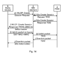
- the third signalling diagram of figure 14 illustrates an initial attach to create an IP session over WLAN 7.
- EAP Extensible Authentication Protocol
- SIM Subscriber Identity Module
- AKA Authentication and Key Agreement
- S2a session is created with the default bearer between the TWAN (as an example of the NW element 4) and PGW 3.
- the example signalling sequence is as follows.
- a Create Session Request d1 is transmitted in WLCP from the radio device 6 to the NW element 4.
- a Create Session Request d2 is transmitted over the S2a interface with TEID from the NW element 4 to the PGW3.
- a Create Session Response e is transmitted over the S2a interface with TEID from the PGW 3 to the NW element 4.
- a Create Session Response f is transmitted in WLCP with TWAN vMAC for a default bearer 8.
- An UL message G with an UL packet is transmitted with the vMAC (as destination MAC address, DST MAC) for the bearer on said bearer from the radio device 6 to the NW element 4.
- An UL message H with the UL packet is transmitted with the TEID from the NE element 4 to the PGW 3 which may then transmit the UL packet further.
- the PGW 3 After having received a DL data packet, the PGW 3 transmits a DL message I with the DL data packet and the TEID to the NW element 4.
- a DL message J with the DL data packet is transmitted with the vMAC (as source MAC address, SRC MAC) for the bearer on said bearer from the NW element 4 to the radio device 6.
- vMAC as source MAC address, SRC MAC
- the network element comprises means (e.g. the processor circuitry 61, possibly in cooperation with the storage unit 62 and/or the communication interface 63) for obtaining 91 an identifier for each of the at least one bearer 8 of the IP session.
- the network element also comprises means (e.g. the processor circuitry 61) for mapping 92 DL data packets of the IP session to the identifier for each of the at least one bearer of the IP session.
- the network element also comprises means (e.g.
- the processor circuitry 61 in cooperation with the communication interface 63) for transmitting 93 each of the DL packets on a bearer of said at least one bearer 8, together with the identifier for the bearer it has been mapped 92 to, over the WLAN 7 to the radio device 6.
- the radio device comprises means (e.g. the processor circuitry 71, possibly in cooperation with the storage unit 72 and/or the communication interface 73) for obtaining 101 an identifier for each of the at least one bearer 8 of the IP session.
- the radio device also comprises means (e.g. the processor circuitry 71) for mapping 102 UL data packets of the IP session to the at least one bearer 8 based on the identifier for each of the at least one bearer.
- the radio device also comprises means (e.g. the processor circuitry 71 in cooperation with the communication interface 73) for transmitting 103 each of the UL packets on a bearer of said at least one bearer 8, together with the identifier for the bearer it has been mapped 102 to, over the WLAN 7.
- the network element comprises means (e.g. the processor circuitry 61, possibly in cooperation with the storage unit 62 and/or the communication interface 63) for obtaining 111 an identifier for each of the at least one bearer 8 of the IP session.
- the network element also comprises means (e.g. the processor circuitry 61) for mapping 112 UL data packets of the IP session to the at least one bearer (8) based on the identifier for each of the at least one bearer.
- the network element also comprises means (e.g. the processor circuitry 61 in cooperation with the communication interface 63) for transmitting 113 each of the UL packets on the bearer 8 which it has been mapped 112 to.
- the computer program 81 comprises computer program code which is able to, when run on processor circuitry 61 of the network element 4, cause the network element to obtain 91 an identifier for each of the at least one bearer 8 of the IP session.
- the code is also able to cause the network element to map 92 DL data packets of the IP session to the identifier for each of the at least one bearer of the IP session.
- the code is also able to cause the network element to transmit 93 each of the DL packets on a bearer of said at least one bearer 8, together with the identifier for the bearer it has been mapped to, over the WLAN 7 to the radio device 6.
- the computer program comprises computer program code which is able to, when run on processor circuitry 71 of the radio device, cause the radio device 6 to obtain 101 an identifier for each of the at least one bearer 8 of the IP session.
- the code is also able to cause the radio device 6 to map 102 UL data packets of the IP session to the identifier for each of the at least one bearer 8 of the IP session.
- the code is also able to cause the radio device 6 to transmit 103 each of the UL packets on a bearer of said at least one bearer 8, together with the identifier for the bearer 8 it has been mapped to, over the WLAN 7.
- the code is also able to cause the network element to map 112 UL data packets of the IP session to the at least one bearer 8 based on the identifier for each of the at least one bearer.
- the code is also able to cause the network element to transmit 113 each of the UL packets on the bearer 8 which it has been mapped 112 to.
- a computer program product 80 comprising an embodiment of a computer program 81 of the present disclosure and a computer readable means 82 on which the computer program is stored.
Abstract
Description
- The present disclosure relates to methods and devices for routing an internet protocol (IP) session of a telecommunication standard over a wireless local area network (WLAN) radio access network (RAN).
- The third generation partnership project (3GPP) defines the concept of bearers. A bearer uniquely identifies traffic flows that receive a common quality of service (QoS) between a user equipment (UE) and a packet data network (PDN) gateway (PGW).
- The currently standardized bearer mechanism is using bearers in the General Packet Radio Service (GPRS) tunnelling protocol (GTP) interface between the Trusted WLAN Access Network (TWAN) gateway (TWAG) and PGW but between UE and the TWAN there is only one pipe. This results in that for uplink (UL) traffic the TWAN has to classify the uplink traffic and send it on the correct bearer.
-
Figure 1 is a schematic block diagram illustrating evolved packet core (EPC and evolved packet system (EPS) concepts, which are also defined in the 3GPP technical specifications (TS) 23.401 and 23.402. The figure explains the bearer concept over a 3GPP radio interface. It is noted that each PDN connection contains at least one bearer. That bearer is called default bearer. Additional bearers within that same PDN connection are called dedicated bearers. The PDN is an IP network such as the Internet or an intranet e.g. a service network. The PGW is a functional node providing access for one or more UE to one or more PDNs. The PDN connection provides a UE with an access channel to a PDN. It is a logical tunnel between UE and PGW. Each PDN connection has a single IP address or prefix. A UE can set up multiple PDN connections, possibly to the same Access Point Name (APN), a string containing the name of the PDN. The PDN connection between the PGW and the UE is further illustrated as containing a plurality of EPS bearers (three infigure 1 ). Each EPS bearer is defined by a set of IP flows with the same QoS profile. Each EPS bearer runs end-to-end (e2e) between the UE and the PGW but is a concatenation of an S5 GTP tunnel between the PGW and a serving gateway (SGW), an S1 GTP tunnel between the SGW and an evolved Node B (eNB), and a radio bearer between the eNB and the UE. - In 3GPP release 11 (Rel-11), the bearer concept is only partially implemented over Wi-Fi, since the EPS bearer concept does not exist over WLAN.
Figure 2 illustrates this. The PGW communicates via the S2a interface between the PGW and a TWAG, comprising or being associated with an access controller (AC). A PDN connection contains one or more S2a bearers (three infigure 2 , between the PGW and the TWAG). S2a supports the bearer concept in that each bearer is a GTP tunnel. Also here there is a PDN connection between the UE and the PGW. However, WLAN does not support the bearer concept. Thus, the S2a bearer is not e2e between the UE and PGW as in access via a cellular 3GPP standard (illustrated infigure 1 ). Instead, each PDN connection is a logical concatenation of one or more S2a tunnels between the PGW and the TWAG and a single L2 point-to-point link between the TWAG and the UE. - Different virtual media access control (MAC) addresses may be used for identifying different PDN connections over WLAN. The functional architecture is shown in
figures 3 and 4 , wherefigure 3 illustrates the functional S2a based architecture in a non-roaming scenario andfigure 4 illustrates the functional split of the TWAN, and wherefigure 4 zooms in what is denoted as the Trusted WLAN Access Network (TWAN) infigure 3 . See TS 23.402 for a further clarification of this architecture. 3GPP Rel-12 allows a UE to setup multiple PDN connections over WLAN. Each PDN connection is identified by a (virtual) MAC address of the TWAG. A change request (CR) 1188 to TS 23.402, incorporated in version 12.3.0 of TS 23.402, describes how (real or virtual) MAC addresses are used to differentiate PDN connections from each other. Still, the bearer concept is not introduced over WLAN, therefore it is not possible to establish multiple bearers within the WLAN segment of the PDN connection. As a consequence, each PDN connection has a single pipe over the WLAN. - It has been realised that it would be convenient to use the bearer concept also between the TWAG and the UE, i.e. over the WLAN. Thus, a bearer identity is defined for identification of each of the bearers between the TWAG and the UE. Without this identity the TWAN will have to classify the uplink traffic and send it on the correct bearer on the S2a interface.
- According to an aspect of the present disclosure, there is provided a method performed by a network element in a communication network for routing an IP session to a radio device over a WLAN, the IP session comprising at least one bearer. The method comprises obtaining an identifier for each of the at least one bearer of the IP session. The method also comprises mapping downlink data packets of the IP session to the identifier for each of the at least one bearer of the IP session. The method also comprises transmitting each of the DL packets on a bearer of said at least one bearer, together with the identifier for the bearer it has been mapped to, over the WLAN to the radio device.
- According to another aspect of the present disclosure, there is provided a computer program product comprising computer-executable components for causing a network element to perform an embodiment of a method of the present disclosure when the computer-executable components are run on processor circuitry comprised in the network element.
- According to another aspect of the present disclosure, there is provided a network element for a communication network for routing an IP session to a radio device over a WLAN, the IP session comprising at least one bearer. The network element comprises processor circuitry, and a storage unit storing instructions that, when executed by the processor circuitry, cause the network element to obtain an identifier for each of the at least one bearer of the IP session. The instructions also cause the network element to map downlink (DL) data packets of the IP session to the identifier for each of the at least one bearer of the IP session. The instructions also cause the network element to transmit each of the DL packets on a bearer of said at least one bearer, together with the identifier for the bearer it has been mapped to, over the WLAN to the radio device.
- According to another aspect of the present disclosure, there is provided a method performed by a radio device in a communication network for routing an IP session over a WLAN, the IP session comprising at least one bearer. The method comprises obtaining an identifier for each of the at least one bearer of the IP session. The method also comprises mapping uplink (UL) data packets of the IP session to the identifier for each of the at least one bearer of the IP session. The method also comprises transmitting each of the UL packets on a bearer of said at least one bearer, together with the identifier for the bearer it has been mapped to, over the WLAN.
- According to another aspect of the present disclosure, there is provided a computer program product comprising computer-executable components for causing a radio device to perform an embodiment of a method of the present disclosure when the computer-executable components are run on processor circuitry comprised in the radio device.
- According to another aspect of the present disclosure, there is provided a radio device for a communication network for routing an IP session over a WLAN, the IP session comprising at least one bearer. The radio device comprises processor circuitry, and a storage unit storing instructions that, when executed by the processor circuitry, cause the radio device to obtain an identifier for each of the at least one bearer of the IP session. The instructions also cause the radio device to map UL data packets of the IP session to the identifier for each of the at least one bearer of the IP session. The instructions also cause the radio device to transmit each of the UL packets on a bearer of said at least one bearer, together with the identifier for the bearer it has been mapped to, over the WLAN.
- According to another aspect of the present disclosure, there is provided a method performed by a network element in a communication network for routing an IP session from a radio device over a WLAN, the IP session comprising at least one bearer. The method comprises obtaining an identifier for each of the at least one bearer of the IP session. The method also comprises mapping UL data packets of the IP session to the at least one bearer based on the identifier for each of the at least one bearer. The method also comprises transmitting each of the UL packets on the bearer which it has been mapped to.
- According to another aspect of the present disclosure, there is provided a network element for a communication network for routing an IP session from a radio device over a WLAN, the IP session comprising at least one bearer. The network element comprises processor circuitry, and a storage unit storing instructions that, when executed by the processor circuitry, cause the network element to obtain an identifier for each of the at least one bearer of the IP session. The instructions also cause the network element to map UL data packets of the IP session to the at least one bearer based on the identifier for each of the at least one bearer. The instructions also cause the network element to transmit each of the UL packets on the bearer which it has been mapped to.
- By using a different identifier, e.g. a real or virtual MAC address, for each of the bearers in an IP session, e.g. over a PDN connection, the bearer concept can be applied also over WLAN in accordance with the present disclosure. For instance, instead of assigning a virtual MAC address per PDN connection, each bearer gets assigned a virtual MAC address. By doing this, the concept of bearers as they are implemented in 3GPP networks can be extended to cover also the link between the radio device, e.g. UE, and TWAN.
- Generally, all terms used in the claims are to be interpreted according to their ordinary meaning in the technical field, unless explicitly defined otherwise herein. All references to "a/an/the element, apparatus, component, means, step, etc." are to be interpreted openly as referring to at least one instance of the element, apparatus, component, means, step, etc., unless explicitly stated otherwise. The steps of any method disclosed herein do not have to be performed in the exact order disclosed, unless explicitly stated. The use of "first", "second" etc. for different features/components of the present disclosure are only intended to distinguish the features/components from other similar features/components and not to impart any order or hierarchy to the features/components.
- Embodiments will be described, by way of example, with reference to the accompanying drawings, in which:
-
Fig 1 is a schematic block diagram illustrating EPC/EPS in accordance with prior art. -
Fig 2 is a schematic block diagram illustrating EPC/EPS when used together with a WLAN RAN in accordance with prior art. -
Fig 3 is a schematic block diagram of a core network cooperating with a TWAN in accordance with prior art. -
Fig 4 is a schematic block diagram of a TWAN in accordance with prior art. -
Fig 5 is a schematic block diagram of an embodiment of a communication network in accordance with the present disclosure. -
Fig 6 is a schematic block diagram of an embodiment of a network element in accordance with the present disclosure. -
Fig 7 is a schematic block diagram of an embodiment of a radio device in accordance with the present disclosure. -
Fig 8 is a schematic illustration of an embodiment of a computer program product in accordance with the present disclosure. -
Fig 9 is a schematic flow chart of an embodiment of a method performed by a network element in accordance with the present disclosure. -
Fig 10 is a schematic flow chart of an embodiment of a method performed by a radio device in accordance with the present disclosure. -
Fig 11 is a schematic flow chart of an embodiment of another method performed by a network element in accordance with the present disclosure. -
Fig 12 is a schematic signalling diagram of an embodiment of a method in accordance with the present disclosure in which the network sets up a bearer in an IP session. -
Fig 13 is a schematic signalling diagram of an embodiment of a method in accordance with the present disclosure in which the radio device sets up a bearer in an IP session. -
Fig 14 is a schematic signalling diagram of an embodiment of a method in accordance with the present disclosure in which the network element sets up an IP session. - Embodiments will now be described more fully hereinafter with reference to the accompanying drawings, in which certain embodiments are shown. However, other embodiments in many different forms are possible within the scope of the present disclosure. Rather, the following embodiments are provided by way of example so that this disclosure will be thorough and complete, and will fully convey the scope of the disclosure to those skilled in the art. Like numbers refer to like elements throughout the description.
- In standardization of WLAN access in 3GPP, support for bearers between TWAG and PGW (s2a interface) has been defined. There is however no solution for how to extend those bearers to the radio device/UE. In accordance with embodiments of the present disclosure MAC addresses e.g. virtual MAC-addresses (vMAC) are used as the way of distinguishing between different bearers over the WELAN interface. There is currently ongoing standardization work in 3GPP to use vMAC for separating PDN connections between UE and TWAG. The vMAC is assigned by a new non-access stratum (NAS) protocol Wireless LAN Control Protocol (WLCP) to be defined by 3GPP. Instead, in accordance with the present disclosure, a dedicated virtual MAC address can be assigned per bearer. Embodiments of the present disclosure using vMAC as bearer identifier allows for one-to-one mapping to the bearers without changing the underlying transport over WLAN between the radio device and the network element, e.g. TWAG. If a new identifier would have been used, it would be necessary to add that to the already standardized frame format between the radio device and the TWAG. It should here be noted that the use of vMAC is only an example of an identifier for each bearer, other examples including real MAC addresses and VLAN IDs. Also, embodiments of the present disclosure may be relevant also for other IP sessions than a PDN connection.
- It may also be possible to add support for Traffic Flow Template (TFT), which is an IP packet filter that is used to define what traffic that qualifies to be transported over a specific bearer. With that in place, it may be possible to combine the QoS concept for WLAN with QoS bearers for 3GPP accesses, by allowing the 3GPP connection to still be active when WLAN access with handover support over the s2a reference point is used. There are thus additional advantages with different embodiments of the present disclosure.
-
Figure 5 is a schematic block diagram of an embodiment of acommunication network 1 in accordance with the present disclosure. APDN 2 is in communication in an IP session with aradio device 6 over a WLAN 7. For the IP session, threebearers 8, e.g. EPS bearers, are set up between aPGW 3 and theradio device 6, via a network element (NW element) 4, e.g. a TWAG, and an access point (AP) 5 of the WLAN 7. Thus, theNW element 4 is logically positioned between thePGW 3 and theAP 5. In contrast to the prior art discussed above, thebearers 8 are thus set up e2e between thePGW 3 and theradio device 6 and the TWAG need not route all data packages over a single pipe over the WLAN RAN. -
Figure 6 is schematic block diagram of an embodiment of anetwork element 4 in accordance with the present disclosure. TheNW element 4, or a part thereof, may e.g. be or be part of a TWAG or an AC, or at least partly be or be part of a node separate from the TWAG or AC. TheNW element 4 comprisesprocessor circuitry 61 e.g. a central processing unit (CPU). Theprocessor circuitry 61 may comprise one or a plurality of processing units in the form of microprocessor(s). However, other suitable devices with computing capabilities could be comprised in theprocessor circuitry 61, e.g. an application specific integrated circuit (ASIC), a field programmable gate array (FPGA) or a complex programmable logic device (CPLD). Theprocessor circuitry 61 is configured to run one or several computer program(s) or software 81 (see alsofigure 8 ) stored in astorage 62 of one or several storage unit(s) e.g. a memory. The storage unit is regarded as a computer readable means 82 (seefigure 8 ) as discussed herein and may e.g. be in the form of a Random Access Memory (RAM), a Flash memory or other solid state memory, or a hard disk, or be a combination thereof. Theprocessor circuitry 61 is also configured to store data in thestorage 62, as needed. TheNW element 4 also comprises acommunication interface 63, e.g. comprising a transmitter and a receiver which may be combined to form a transceiver or be present as distinct units. Thecommunication interface 63 is configured to cooperate with theprocessor circuitry 61 to transform data bits to be transmitted to a suitable signal. Similarly, thecommunication interface 63 is configured to cooperate with theprocessor circuitry 61 to transform a received signal to data bits. -
Figure 7 is a schematic block diagram of an embodiment of aradio device 6 in accordance with the present disclosure. Theradio device 6 may be any device or user equipment (UE), mobile or stationary, enabled to communicate over a radio cannel in acommunications network 1, for instance but not limited to e.g. mobile phone, smart phone, modem, sensors, meters, vehicles (e.g. a car), household appliances, medical appliances, media players, cameras, or any type of consumer electronic, for instance but not limited to television, radio, lighting arrangements, tablet computer, laptop, or personal computer (PC). Theradio device 6 comprisesprocessor circuitry 71 e.g. a central processing unit (CPU). Theprocessor circuitry 71 may comprise one or a plurality of processing units in the form of microprocessor(s). However, other suitable devices with computing capabilities could be comprised in theprocessor circuitry 71, e.g. an application specific integrated circuit (ASIC), a field programmable gate array (FPGA) or a complex programmable logic device (CPLD). Theprocessor circuitry 71 is configured to run one or several computer program(s) or software 81 (see alsofigure 8 ) stored in astorage 72 of one or several storage unit(s) e.g. a memory. The storage unit is regarded as a computer readable means 82 (seefigure 8 ) as discussed herein and may e.g. be in the form of a Random Access Memory (RAM), a Flash memory or other solid state memory, or a hard disk, or be a combination thereof. Theprocessor circuitry 71 is also configured to store data in thestorage 72, as needed. Theradio device 6 also comprises aradio communication interface 73, e.g. comprising a receiver, a transmitter and an antenna, which may be combined to form a transceiver or be present as distinct units. Theradio interface 73 is configured to cooperate with theprocessor circuitry 71 to transform data bits to be transmitted over an air interface to a suitable radio signal in accordance with the WLAN RAN via which the data bits are to be transmitted. Similarly, theradio interface 73 is configured to cooperate with theprocessor circuitry 71 to transform a received radio signal to data bits. -
Figure 8 illustrates acomputer program product 80. Thecomputer program product 80 comprises a computerreadable medium 82 comprising acomputer program 81 in the form of computer-executable components 81. The computer program/computer-executable components 81 may be configured to cause aNW element 4 or aradio device 6, e.g. as discussed herein, to perform an embodiment of a method of the present disclosure. The computer program/computer-executable components may be run on theprocessor circuitry 61/71 of the element/device 4/6 for causing it to perform the method. Thecomputer program product 80 may e.g. be comprised in a storage unit ormemory 62/72 comprised in the element/device 4/6 and associated with theprocessor circuitry 61/71. Alternatively, thecomputer program product 80 may be, or be part of, a separate, e.g. mobile, storage means, such as a computer readable disc, e.g. CD or DVD or hard disc/drive, or a solid state storage medium, e.g. a RAM or Flash memory. -
Figure 9 is a schematic flow chart of an embodiment of a method performed by anetwork element 4 in accordance with the present disclosure. TheNW element 4 is in acommunication network 1 and the method is for routing an IP session, e.g. a PDN connection, to aradio device 6 over a WLAN 7. The IP session comprises at least onebearer 8, typically a plurality ofbearers 8. An identifier for each of the at least onebearer 8 of the IP session is obtained 91. Thus, if the IP session comprises a plurality ofbearers 8, each of those bearers has a different identifier which is obtained 91 by theNW element 4. The NW element may e.g. obtain 91 the identifier(s) from itsstorage 62 or from a message received from outside of theNW element 4. As discussed herein, the identifier may e.g. be a vMAC. DL data packets of the IP session are mapped to the identifier for each of the at least one bearer of the IP session. For instance, DL packets comes from a plurality of PGW to TWAG GTP tunnels, each having a different tunnel ID. In the DL theNW element 4, e.g. TWAG, adds an Ethernet header with the identifier, e.g. vMAC, obtained 91 to each packet coming from a specific tunnel, and the procedure is repeated for each of the tunnels. Thus, a plurality of bearers are defined by means of being associated with different identifiers, e.g. vMAC, when transmitted over the WLAN 7. Each of the DL packets is transmitted 93 on abearer 8 of said at least one bearer, together with the identifier for the bearer it has been mapped 92 to, over the WLAN 7 to theradio device 6. Thus, the DL packet is transmitted together with the identifier it has been mapped 92 to, e.g. in its Ethernet header, on thebearer 8 for which said identifier has been obtained 91. -
Figure 10 is a schematic flow chart of an embodiment of a method performed by aradio device 6 in accordance with the present disclosure. The radio device is in in acommunication network 1 and the method is for routing an IP session, e.g. a PDN connection, over a WLAN 7. The IP session comprises at least onebearer 8, typically a plurality ofbearers 8. An identifier for each of the at least onebearer 8 of the IP session is obtained 101. Thus, if the IP session comprises a plurality ofbearers 8, each of those bearers has a different identifier which is obtained 101 by theradio device 6. Theradio device 6 may e.g. obtain 101 the identifier(s) from itsstorage 72 or from a message received from outside of theradio device 6. As discussed herein, the identifier may e.g. be a vMAC. UL data packets of the IP session are mapped 102 to the at least onebearer 8 based on the identifier for each of the at least one bearer. Thus, since each of thebearers 8 is associated with its own identifier differentiating it from the other bearers, theradio device 6 may e.g. add the proper identifier to an Ethernet header of each UL packet, thereby defining the different bearers of the IP session. Thus, a plurality of bearers are defined by means of being associated with different identifiers, e.g. vMAC, when transmitted over the WLAN 7. Each of the UL packets is transmitted 103 on abearer 8 of said at least one bearer, together with the identifier for the bearer it has been mapped 102 to, over the WLAN 7 e.g. to/via theNW element 4. Thus, the UL packet is transmitted on thebearer 8 it has been mapped 102 to, together with the identifier of the bearer it has been mapped 102 to. -
Figure 11 is a schematic flow chart of an embodiment of a method performed by anetwork element 4 in accordance with the present disclosure. TheNW element 4 is in acommunication network 1 and the method is for routing an IP session, e.g. a PDN connection, from aradio device 6 wherein theradio device 6 transmits over a WLAN 7 for the IP session. The IP session comprises at least onebearer 8, typically a plurality ofbearers 8. An identifier for each of the at least onebearer 8 of the IP session is obtained 111. Thus, if the IP session comprises a plurality ofbearers 8, each of those bearers has a different identifier which is obtained 111 by theNW element 4. TheNW element 4 may e.g. obtain 111 the identifier(s) from itsstorage 62 or from a message received from outside of theNW element 4. As discussed herein, the identifier may e.g. be a vMAC. UL data packets of the IP session are mapped to the at least one bearer (8) based on the identifier for each of the at least one bearer. For instance, UL packets comes from a plurality ofbearers 8 defined by means of being associated with different identifier e.g. added to an Ethernet header of each of the packets by theradio device 6. TheNW element 4, e.g. a TWAG, may then map 112 each of the packets to each of thebearers 8 for the section of the bearers between theNW element 4 and the PGW, e.g. corresponding to TWAG to PGW GTP tunnels each having a different tunnel ID. Each of the UL packets is transmitted 93 on thebearer 8 which it has been mapped 112 to, e.g. to aPGW 3. - In some embodiments of the present disclosure the at least one
bearer 8 is a plurality of bearers, and the obtaining 91 of an identifier comprises obtaining a different identifier for each of the plurality ofbearers 8. Thus, there is a plurality of bearers in the IP session and each has a unique (among the plurality of bearers) identifier. - In some embodiments of the present disclosure the identifier is a media access control (MAC) address or a virtual local area network (VLAN) identification (ID). Herein MAC addresses are much discussed as an example of the identifiers, but other identifiers are also possible, e.g. VLAN IDs. Preferably the identifier is a MAC address such as a virtual MAC address (vMAC).
- In some embodiments of the present disclosure the obtaining 91 or 101 an identifier comprises the
NW element 4 selecting and assigning an identifier for each of the at least onebearer 8. This implies that the identifier(s) is actively assigned to each of the at least one bearers, instead of e.g. receiving data packets with identifiers already assigned to bearer(s). - In some embodiments of the present disclosure the
network element 4 is an access controller (AC), wherein the AC is comprised in, or otherwise associated with, a TWAG. It may be convenient to include the functionality of theNW element 4 in an AC and/or a TWAG. - In some embodiments of the present disclosure the
network element 4 is in the IP session logically situated between aPGW 3 and aWLAN AP 5. - In some embodiments of the present disclosure the obtaining 101 an identifier comprises the
radio device 4 receiving the identifier in a message D or f from thenetwork element 4 in thecommunication network 1. - The following, different signalling diagrams are used to explain example embodiments of the present disclosure in more detail. Note that using WLCP for setting up bearers within a PDN connection has not been specified yet so the names of messages are just assumptions or suggestions.
- The
bearer 8 has a corresponding user plane and control plane TEID both on the PGW and TWAN side. The TWAN will then send information about this PDN connection/bearer to theradio device 6 using WLCP. Also in the WLCP message there may be a TFT filter that instruct theradio device 6 what traffic to send on thatparticular bearer 8. Also, to get proper QoS, a differentiated services code point (DSCP) value and/or WLAN access may be assigned to the bearer 8 (mapped from QoS class identifier (QCI) over S2a). When theradio device 6 sends an uplink packet matching the TFT, the destination MAC address may be equal to vMAC of thebearer 8. When TWAN sends a downlink packet on this bearer to theradio device 6, the vMAC is used as source MAC address. - The first signalling diagram of
figure 12 illustrates a network initiated creation of adedicated bearer 8 over WLAN 7. The network initiates the creation of adedicated bearer 8 on an existing PDN connection. A new vMAC, at least unique for that UE, is assigned to the bearer. First the bearer is set up, after which thebearer 8 is used for transmission of UL and DL data packets. The example signalling sequence is as follows. - A Bearer Request C is sent from the
PGW 3 to theNW element 4 over the S2a interface with a Tunnel Endpoint Identifier (TEID). - A Create Bearer message D of WLCP with a TWAN vMAC for the bearer is sent from the
NW element 4 to theradio device 6. - A Create Bearer Response E of WLCP is sent from the
radio device 6 to theNW element 4. - A Create Bearer Response F is sent over the S2a interface from the
NW element 4 to thePGW 3. - An UL message G with an UL packet is transmitted with the vMAC (as destination MAC address, DST MAC) for the bearer on said bearer from the
radio device 6 to theNW element 4. - An UL message H with the UL packet is transmitted with the TEID from the
NE element 4 to thePGW 3 which may then transmit the UL packet further. - After having received a DL data packet, the
PGW 3 transmits a DL message I with the DL data packet and the TEID to theNW element 4. - A DL message J with the DL data packet is transmitted with the vMAC (as source MAC address, SRC MAC) for the bearer on said bearer from the
NW element 4 to theradio device 6. - The second signalling diagram of
figure 13 illustrates a radio device initiated creation of adedicated bearer 8 over WLAN 7. Theradio device 6 initiates the creation of adedicated bearer 8 on an existing PDN connection. A new vMAC, at least unique for that UE, is assigned to the bearer. The radio device commands the network to set up the bearer, after which the signalling sequence is as infigure 12 of example 1. First the bearer is set up, then thebearer 8 is used for transmission of UL and DL data packets. The example signalling sequence is as follows. - A Bearer Resource Command A of WLCP is transmitted from the
radio device 6 to theNW element 4. - A Bearer Resource Command B is transmitted over the S2a interface from the
NW element 4 to thePGW 3. - A Bearer Request C is sent from the
PGW 3 to theNW element 4 over the S2a interface with a Tunnel Endpoint Identifier (TEID). - A Create Bearer message D of WLCP with a TWAN vMAC for the bearer is sent from the
NW element 4 to theradio device 6. - A Create Bearer Response E of WLCP is sent from the
radio device 6 to theNW element 4. - A Create Bearer Response F is sent over the S2a interface from the
NW element 4 to thePGW 3. - An UL message G with an UL packet is transmitted with the vMAC (as destination MAC address, DST MAC) for the bearer on said bearer from the
radio device 6 to theNW element 4. - An UL message H with the UL packet is transmitted with the TEID from the
NE element 4 to thePGW 3 which may then transmit the UL packet further. - After having received a DL data packet, the
PGW 3 transmits a DL message I with the DL data packet and the TEID to theNW element 4. - A DL message J with the DL data packet is transmitted with the vMAC (as source MAC address, SRC MAC) for the bearer on said bearer from the
NW element 4 to theradio device 6. - The third signalling diagram of
figure 14 illustrates an initial attach to create an IP session over WLAN 7. First theradio device 6 authenticates, typically using EAP-SIM (Extensible Authentication Protocol (EAP), Subscriber Identity Module (SIM))/ Authentication and Key Agreement (AKA) or AKA'. Then an S2a session is created with the default bearer between the TWAN (as an example of the NW element 4) andPGW 3. The example signalling sequence is as follows. - A Create Session Request d1 is transmitted in WLCP from the
radio device 6 to theNW element 4. - A Create Session Request d2 is transmitted over the S2a interface with TEID from the
NW element 4 to the PGW3. - A Create Session Response e is transmitted over the S2a interface with TEID from the
PGW 3 to theNW element 4. - A Create Session Response f is transmitted in WLCP with TWAN vMAC for a
default bearer 8. - An UL message G with an UL packet is transmitted with the vMAC (as destination MAC address, DST MAC) for the bearer on said bearer from the
radio device 6 to theNW element 4. - An UL message H with the UL packet is transmitted with the TEID from the
NE element 4 to thePGW 3 which may then transmit the UL packet further. - After having received a DL data packet, the
PGW 3 transmits a DL message I with the DL data packet and the TEID to theNW element 4. - A DL message J with the DL data packet is transmitted with the vMAC (as source MAC address, SRC MAC) for the bearer on said bearer from the
NW element 4 to theradio device 6. - Below follow some other aspects of the present disclosure.
- According to an aspect of the present disclosure, there is provided a
network element 4 for acommunication network 1 for routing an IP session to aradio device 6 over a WLAN 7, the IP session comprising at least onebearer 8. The network element comprises means (e.g. theprocessor circuitry 61, possibly in cooperation with thestorage unit 62 and/or the communication interface 63) for obtaining 91 an identifier for each of the at least onebearer 8 of the IP session. The network element also comprises means (e.g. the processor circuitry 61) formapping 92 DL data packets of the IP session to the identifier for each of the at least one bearer of the IP session. The network element also comprises means (e.g. theprocessor circuitry 61 in cooperation with the communication interface 63) for transmitting 93 each of the DL packets on a bearer of said at least onebearer 8, together with the identifier for the bearer it has been mapped 92 to, over the WLAN 7 to theradio device 6. - According to another aspect of the present disclosure, there is provided a
radio device 6 for acommunication network 1 for routing an IP session over a WLAN 7, the IP session comprising at least onebearer 8. The radio device comprises means (e.g. theprocessor circuitry 71, possibly in cooperation with thestorage unit 72 and/or the communication interface 73) for obtaining 101 an identifier for each of the at least onebearer 8 of the IP session. The radio device also comprises means (e.g. the processor circuitry 71) formapping 102 UL data packets of the IP session to the at least onebearer 8 based on the identifier for each of the at least one bearer. The radio device also comprises means (e.g. theprocessor circuitry 71 in cooperation with the communication interface 73) for transmitting 103 each of the UL packets on a bearer of said at least onebearer 8, together with the identifier for the bearer it has been mapped 102 to, over the WLAN 7. - According to another aspect of the present disclosure, there is provided a
network element 4 for acommunication network 1 for routing an IP session from aradio device 6 over a WLAN 7, the IP session comprising at least onebearer 8. The network element comprises means (e.g. theprocessor circuitry 61, possibly in cooperation with thestorage unit 62 and/or the communication interface 63) for obtaining 111 an identifier for each of the at least onebearer 8 of the IP session. The network element also comprises means (e.g. the processor circuitry 61) formapping 112 UL data packets of the IP session to the at least one bearer (8) based on the identifier for each of the at least one bearer. The network element also comprises means (e.g. theprocessor circuitry 61 in cooperation with the communication interface 63) for transmitting 113 each of the UL packets on thebearer 8 which it has been mapped 112 to. - According to another aspect of the present disclosure, there is provided a
computer program 81 for anetwork element 4 in acommunication network 1 for routing an IP session to aradio device 6 over a WLAN 7, the IP session comprising at least onebearer 8. Thecomputer program 81 comprises computer program code which is able to, when run onprocessor circuitry 61 of thenetwork element 4, cause the network element to obtain 91 an identifier for each of the at least onebearer 8 of the IP session. The code is also able to cause the network element to map 92 DL data packets of the IP session to the identifier for each of the at least one bearer of the IP session. The code is also able to cause the network element to transmit 93 each of the DL packets on a bearer of said at least onebearer 8, together with the identifier for the bearer it has been mapped to, over the WLAN 7 to theradio device 6. - According to another aspect of the present disclosure, there is provided a
computer program 81 for aradio device 6 in acommunication network 6 for routing an IP session over a WLAN 7, the IP session comprising at least onebearer 8. The computer program comprises computer program code which is able to, when run onprocessor circuitry 71 of the radio device, cause theradio device 6 to obtain 101 an identifier for each of the at least onebearer 8 of the IP session. The code is also able to cause theradio device 6 to map 102 UL data packets of the IP session to the identifier for each of the at least onebearer 8 of the IP session. The code is also able to cause theradio device 6 to transmit 103 each of the UL packets on a bearer of said at least onebearer 8, together with the identifier for thebearer 8 it has been mapped to, over the WLAN 7. - According to another aspect of the present disclosure, there is provided a
computer program 81 for anetwork element 4 in acommunication network 1 for routing an IP session to aradio device 6 over a WLAN 7, the IP session comprising at least onebearer 8, thecomputer program 81 comprising computer program code which is able to, when run onprocessor circuitry 61 of thenetwork element 4, cause the network element to obtain 111 an identifier for each of the at least onebearer 8 of the IP session. The code is also able to cause the network element to map 112 UL data packets of the IP session to the at least onebearer 8 based on the identifier for each of the at least one bearer. The code is also able to cause the network element to transmit 113 each of the UL packets on thebearer 8 which it has been mapped 112 to. - According to another aspect of the present disclosure, there is provided a
computer program product 80 comprising an embodiment of acomputer program 81 of the present disclosure and a computer readable means 82 on which the computer program is stored. - The present disclosure has mainly been described above with reference to a few embodiments. However, as is readily appreciated by a person skilled in the art, other embodiments than the ones disclosed above are equally possible within the scope of the present disclosure, as defined by the appended claims.
Claims (18)
- A method performed by a network element (4) in a communication network (1) for routing an IP session to a radio device (6) over a wireless local area network, WLAN, (7) the IP session comprising at least one bearer (8), the method comprising:obtaining (91) an identifier for each of the at least one bearer (8) of the IP session;mapping (92) downlink, DL, data packets of the IP session to the identifier for each of the at least one bearer of the IP session; andtransmitting (93) each of the DL packets on a bearer of said at least one bearer (8), together with the identifier for the bearer it has been mapped (92) to, over the WLAN (7) to the radio device (6).
- The method of claim 1, wherein the at least one bearer (8) is a plurality of bearers, and wherein the obtaining (91) an identifier comprises obtaining a different identifier for each of the plurality of bearers (8).
- The method of claim 1 or 2, wherein the identifier is a media access control, MAC, address or a virtual local area network, VLAN, identification, ID, preferably a MAC address such as a virtual MAC address.
- The method of any preceding claim, wherein the obtaining (91) an identifier comprises selecting and assigning an identifier for each of the at least one bearer (8).
- The method of any preceding claim, wherein the network element (4) is a trusted WLAN access gateway, TWAG, or an access controller, AC.
- The method of any preceding claim 1-4, wherein the network element (4) is an AC, and wherein the AC is comprised in, or otherwise associated with, a TWAG.
- The method of any preceding claim, wherein the network element (4) is in the IP session situated between a packet data network, PDN, gateway, PGW, (3) and a WLAN access point, AP (5).
- The method of any preceding claim, wherein the IP session is over a PDN connection comprising the at least one bearer (8).
- A computer program product (80) comprising computer-executable components (81) for causing a network element, (4) to perform the method of any one of claims 1-8 when the computer-executable components are run on processor circuitry (61) comprised in the network element.
- A network element (4) for a communication network (1) for routing an IP session to a radio device (6) over a wireless local area network, WLAN, (7) the IP session comprising at least one bearer (8), the network element comprising:processor circuitry (61); anda storage unit (62) storing instructions that, when executed by the processor circuitry (61), cause the network element (4) to:obtain an identifier for each of the at least one bearer (8) of the IP session;map downlink, DL, data packets of the IP session to the identifier for each of the at least one bearer of the IP session; andtransmit each of the DL packets on a bearer of said at least one bearer (8),together with the identifier for the bearer it has been mapped to, over the WLAN (7) to the radio device (6).
- A method performed by a radio device (6) in a communication network (1) for routing an IP session over a wireless local area network, WLAN, (7) the IP session comprising at least one bearer (8), the method comprising:obtaining (101) an identifier for each of the at least one bearer (8) of the IP session;mapping (102) uplink, UL, data packets of the IP session to the identifier for each of the at least one bearer (8) of the IP session; andtransmitting (103) each of the UL packets on a bearer of said at least one bearer (8), together with the identifier for the bearer it has been mapped to, over the WLAN (7).
- The method of claim 11, wherein the obtaining (101) an identifier comprises receiving the identifier in a message (D; f) from a network element (4) in the communication network (1), e.g. from an access controller, AC, or trusted WLAN access gateway, TWAG.
- A computer program product (80) comprising computer-executable components (81) for causing a radio device (6) to perform the method of claim 11 or 12 when the computer-executable components are run on processor circuitry (71) comprised in the radio device (6).
- A radio device (6) for a communication network (1) for routing an IP session over a wireless local area network, WLAN, (7) the IP session comprising at least one bearer (8), the radio device comprising:processor circuitry (71); anda storage unit (72) storing instructions that, when executed by the processor circuitry (71), cause the radio device (6) to:obtain an identifier for each of the at least one bearer (8) of the IP session;map uplink, UL, data packets of the IP session to the identifier for each of the at least one bearer (8) of the IP session; andtransmit each of the UL packets on a bearer of said at least one bearer (8),together with the identifier for the bearer (8) it has been mapped to, over the WLAN (7).
- A method performed by a network element (4) in a communication network (1) for routing an IP session from a radio device (6) over a wireless local area network, WLAN, (7) the IP session comprising at least one bearer (8), the method comprising:obtaining (111) an identifier for each of the at least one bearer (8) of the IP session;mapping (112) uplink, UL, data packets of the IP session to the at least one bearer (8) based on the identifier for each of the at least one bearer; andtransmitting (113) each of the UL packets on the bearer (8) which it has been mapped (112) to.
- The method of claim 15, wherein the transmitting (113) is to a packet data network, PDN, gateway, PGW, (3).
- A computer program product (80) comprising computer-executable components (81) for causing a network element (4) to perform the method of any one of claims 15-16 when the computer-executable components are run on processor circuitry (61) comprised in the network element.
- A network element (4) for a communication network (1) for routing an IP session from a radio device (6) over a wireless local area network, WLAN, (7) the IP session comprising at least one bearer (8), the network element comprising:processor circuitry (61); anda storage unit (62) storing instructions that, when executed by the processor circuitry (61), cause the network element (4) to:obtain an identifier for each of the at least one bearer (8) of the IP session;map uplink, UL, data packets of the IP session to the at least one bearer (8) based on the identifier for each of the at least one bearer; andtransmit each of the UL packets on the bearer (8) which it has been mapped to.
Priority Applications (2)
| Application Number | Priority Date | Filing Date | Title |
|---|---|---|---|
| EP14151786.2A EP2897438A1 (en) | 2014-01-20 | 2014-01-20 | Routing an IP session over WLAN |
| US14/599,080 US9794852B2 (en) | 2014-01-20 | 2015-01-16 | Routing an IP session over WLAN |
Applications Claiming Priority (1)
| Application Number | Priority Date | Filing Date | Title |
|---|---|---|---|
| EP14151786.2A EP2897438A1 (en) | 2014-01-20 | 2014-01-20 | Routing an IP session over WLAN |
Publications (1)
| Publication Number | Publication Date |
|---|---|
| EP2897438A1 true EP2897438A1 (en) | 2015-07-22 |
Family
ID=49958331
Family Applications (1)
| Application Number | Title | Priority Date | Filing Date |
|---|---|---|---|
| EP14151786.2A Ceased EP2897438A1 (en) | 2014-01-20 | 2014-01-20 | Routing an IP session over WLAN |
Country Status (2)
| Country | Link |
|---|---|
| US (1) | US9794852B2 (en) |
| EP (1) | EP2897438A1 (en) |
Cited By (1)
| Publication number | Priority date | Publication date | Assignee | Title |
|---|---|---|---|---|
| CN110972216A (en) * | 2018-09-30 | 2020-04-07 | 华为技术有限公司 | Communication method and device |
Families Citing this family (3)
| Publication number | Priority date | Publication date | Assignee | Title |
|---|---|---|---|---|
| US9807624B2 (en) * | 2015-06-01 | 2017-10-31 | T-Mobile Usa, Inc. | Self-adjusting wireless in-band backhaul |
| DE112017004736T5 (en) * | 2016-09-21 | 2019-06-19 | Mavenir Systems, Inc. | Method and system for session resilience in packet gateways |
| US20190028931A1 (en) * | 2017-07-19 | 2019-01-24 | Nokia Of America Corporation | Method and apparatus for quality of service differentiation via a trusted wireless local area network |
Citations (6)
| Publication number | Priority date | Publication date | Assignee | Title |
|---|---|---|---|---|
| EP2075959A1 (en) * | 2007-12-27 | 2009-07-01 | THOMSON Licensing | Apparatus amd method for concurently accessing multiple wireless networks (WLAN/WPAN) |
| EP2166735A1 (en) * | 2008-09-19 | 2010-03-24 | Nokia Siemens Networks OY | Method and device for data processing and communication system comprising such device |
| WO2011157129A2 (en) * | 2011-05-31 | 2011-12-22 | 华为技术有限公司 | Data transmission method, stream distribution node device, user equipment and system |
| WO2012149400A2 (en) * | 2011-04-29 | 2012-11-01 | Gupta Vivek G | Trusted wlan connectivity to 3gpp evolved packet core |
| WO2013121492A1 (en) * | 2012-02-17 | 2013-08-22 | Panasonic Corporation | Method and mobile terminal for controlling multiple flows over wlan access |
| WO2013144714A2 (en) * | 2012-03-31 | 2013-10-03 | Alcatel Lucent | Method of managing data bearers in a wireless access device and ues |
Family Cites Families (5)
| Publication number | Priority date | Publication date | Assignee | Title |
|---|---|---|---|---|
| EP1884061A1 (en) * | 2005-05-16 | 2008-02-06 | Telefonaktiebolaget LM Ericsson (publ) | Means and method for ciphering and transmitting data in integrated networks |
| US8406137B2 (en) * | 2010-06-28 | 2013-03-26 | Alcatel Lucent | Method and system for generating PCC rules based on service requests |
| EP2688363B1 (en) * | 2011-05-31 | 2017-11-29 | Huawei Technologies Co., Ltd. | System, device for convergence transmission and method for data distribution convergence |
| CN103428811A (en) * | 2012-05-21 | 2013-12-04 | 中兴通讯股份有限公司 | Co-existence support for 3GPP device and fixed device bearer transport over fixed broadband access network |
| US11102689B2 (en) | 2013-01-03 | 2021-08-24 | Apple Inc. | Packet data connections in a wireless communication system using a wireless local area network |
-
2014
- 2014-01-20 EP EP14151786.2A patent/EP2897438A1/en not_active Ceased
-
2015
- 2015-01-16 US US14/599,080 patent/US9794852B2/en active Active
Patent Citations (7)
| Publication number | Priority date | Publication date | Assignee | Title |
|---|---|---|---|---|
| EP2075959A1 (en) * | 2007-12-27 | 2009-07-01 | THOMSON Licensing | Apparatus amd method for concurently accessing multiple wireless networks (WLAN/WPAN) |
| EP2166735A1 (en) * | 2008-09-19 | 2010-03-24 | Nokia Siemens Networks OY | Method and device for data processing and communication system comprising such device |
| WO2012149400A2 (en) * | 2011-04-29 | 2012-11-01 | Gupta Vivek G | Trusted wlan connectivity to 3gpp evolved packet core |
| WO2011157129A2 (en) * | 2011-05-31 | 2011-12-22 | 华为技术有限公司 | Data transmission method, stream distribution node device, user equipment and system |
| EP2709418A2 (en) * | 2011-05-31 | 2014-03-19 | Huawei Technologies Co., Ltd. | Data transmission method, stream distribution node device, user equipment and system |
| WO2013121492A1 (en) * | 2012-02-17 | 2013-08-22 | Panasonic Corporation | Method and mobile terminal for controlling multiple flows over wlan access |
| WO2013144714A2 (en) * | 2012-03-31 | 2013-10-03 | Alcatel Lucent | Method of managing data bearers in a wireless access device and ues |
Non-Patent Citations (1)
| Title |
|---|
| "3rd Generation Partnership Project; Technical Specification Group Services and System Aspects; Study on S2a Mobility based On GTP & WLAN access to EPC (SaMOG); Stage 2 (Release 12)", 3GPP STANDARD; 3GPP TR 23.852, 3RD GENERATION PARTNERSHIP PROJECT (3GPP), MOBILE COMPETENCE CENTRE ; 650, ROUTE DES LUCIOLES ; F-06921 SOPHIA-ANTIPOLIS CEDEX ; FRANCE, vol. SA WG2, no. V1.2.0, 20 July 2012 (2012-07-20), pages 1 - 63, XP050648988 * |
Cited By (1)
| Publication number | Priority date | Publication date | Assignee | Title |
|---|---|---|---|---|
| CN110972216A (en) * | 2018-09-30 | 2020-04-07 | 华为技术有限公司 | Communication method and device |
Also Published As
| Publication number | Publication date |
|---|---|
| US9794852B2 (en) | 2017-10-17 |
| US20150208317A1 (en) | 2015-07-23 |
Similar Documents
| Publication | Publication Date | Title |
|---|---|---|
| US11516862B2 (en) | Communication method and apparatus | |
| US10893434B2 (en) | UE session management QoS capability negotiation and QoS control realization | |
| CN106465227B (en) | Method and apparatus for supporting network IP flow mobility via multiple wireless accesses | |
| US11102689B2 (en) | Packet data connections in a wireless communication system using a wireless local area network | |
| US9955490B2 (en) | Radio communication apparatus, network node, user node, core network, and methods implemented therein | |
| JP6665937B2 (en) | Radio access network node, radio terminal, and methods thereof | |
| EP2676463B1 (en) | Mobile router and method in an eps | |
| JP6521156B2 (en) | Radio communication system, mobile station and radio station | |
| US20220014475A1 (en) | Packet delay parameter obtaining method, system, and apparatus | |
| US10506644B2 (en) | Radio access network device, data processing method, and IP packet processing method | |
| US10728932B2 (en) | Wireless communications system, base station, and mobile station | |
| KR101324251B1 (en) | Relay station and relay method for relaying communications between user equipment and base stations | |
| CN107005891B (en) | Method for establishing load, user equipment and base station | |
| CN105230072A (en) | For controlling the method and apparatus of the quality of serving in wireless lans | |
| WO2017177753A1 (en) | Flow-based bearer management method, and data transmission method and device | |
| US20150334697A1 (en) | Method for Implementing Radio Resource Control Protocol Function, Macro Base Station, and Micro Cell Node | |
| US9794852B2 (en) | Routing an IP session over WLAN | |
| WO2019175805A1 (en) | User plane qos bearer control method for 5g fixed access | |
| EP4037262A1 (en) | Mechanism for realizing lwa/lwip aggregator function | |
| CN114467288A (en) | Data packet transmission method and device | |
| US20150245401A1 (en) | Methods and apparatus for converting a single radio-access technology connection into a multiple radio-access technology connection | |
| WO2020192250A1 (en) | Method and apparatus for establishing radio bearer | |
| KR20200117356A (en) | Method and apparatus for transmitting signal based on quality of service in mobile communication network | |
| KR20190129378A (en) | Method and apparatus for transmitting and receiving packet through unified transport network in communication system | |
| BR112013030072B1 (en) | CONVERGENT TRANSMISSION SYSTEM, DATA DOWNLOAD AND CONVERGENCE NODE AND USER EQUIPMENT |
Legal Events
| Date | Code | Title | Description |
|---|---|---|---|
| PUAI | Public reference made under article 153(3) epc to a published international application that has entered the european phase |
Free format text: ORIGINAL CODE: 0009012 |
|
| 17P | Request for examination filed |
Effective date: 20140120 |
|
| AK | Designated contracting states |
Kind code of ref document: A1 Designated state(s): AL AT BE BG CH CY CZ DE DK EE ES FI FR GB GR HR HU IE IS IT LI LT LU LV MC MK MT NL NO PL PT RO RS SE SI SK SM TR |
|
| AX | Request for extension of the european patent |
Extension state: BA ME |
|
| 17P | Request for examination filed |
Effective date: 20160113 |
|
| RBV | Designated contracting states (corrected) |
Designated state(s): AL AT BE BG CH CY CZ DE DK EE ES FI FR GB GR HR HU IE IS IT LI LT LU LV MC MK MT NL NO PL PT RO RS SE SI SK SM TR |
|
| 17Q | First examination report despatched |
Effective date: 20160805 |
|
| STAA | Information on the status of an ep patent application or granted ep patent |
Free format text: STATUS: EXAMINATION IS IN PROGRESS |
|
| STAA | Information on the status of an ep patent application or granted ep patent |
Free format text: STATUS: THE APPLICATION HAS BEEN REFUSED |
|
| STAA | Information on the status of an ep patent application or granted ep patent |
Free format text: STATUS: THE APPLICATION HAS BEEN REFUSED |
|
| 18R | Application refused |
Effective date: 20180920 |