EP2897255A2 - Method for mounting stator core on generator and generator and stator core assembly using the same - Google Patents
Method for mounting stator core on generator and generator and stator core assembly using the same Download PDFInfo
- Publication number
- EP2897255A2 EP2897255A2 EP15151303.3A EP15151303A EP2897255A2 EP 2897255 A2 EP2897255 A2 EP 2897255A2 EP 15151303 A EP15151303 A EP 15151303A EP 2897255 A2 EP2897255 A2 EP 2897255A2
- Authority
- EP
- European Patent Office
- Prior art keywords
- stator core
- key
- bars
- frame body
- donut
- Prior art date
- Legal status (The legal status is an assumption and is not a legal conclusion. Google has not performed a legal analysis and makes no representation as to the accuracy of the status listed.)
- Granted
Links
- 238000000034 method Methods 0.000 title claims abstract description 31
- 230000002093 peripheral effect Effects 0.000 claims abstract description 47
- 238000010030 laminating Methods 0.000 claims abstract description 4
- 238000003475 lamination Methods 0.000 claims description 26
- 239000012809 cooling fluid Substances 0.000 claims description 9
- 238000001816 cooling Methods 0.000 claims description 7
- 235000012489 doughnuts Nutrition 0.000 claims 2
- 238000003801 milling Methods 0.000 description 8
- 238000009434 installation Methods 0.000 description 4
- 238000003466 welding Methods 0.000 description 4
- 238000003754 machining Methods 0.000 description 3
- 238000004519 manufacturing process Methods 0.000 description 2
- UFHFLCQGNIYNRP-UHFFFAOYSA-N Hydrogen Chemical compound [H][H] UFHFLCQGNIYNRP-UHFFFAOYSA-N 0.000 description 1
- 230000015572 biosynthetic process Effects 0.000 description 1
- 238000007796 conventional method Methods 0.000 description 1
- 229910052739 hydrogen Inorganic materials 0.000 description 1
- 239000001257 hydrogen Substances 0.000 description 1
- 230000006698 induction Effects 0.000 description 1
- 229920001296 polysiloxane Polymers 0.000 description 1
- 238000010248 power generation Methods 0.000 description 1
- 238000005493 welding type Methods 0.000 description 1
- 239000002023 wood Substances 0.000 description 1
Images


Classifications
-
- H—ELECTRICITY
- H02—GENERATION; CONVERSION OR DISTRIBUTION OF ELECTRIC POWER
- H02K—DYNAMO-ELECTRIC MACHINES
- H02K1/00—Details of the magnetic circuit
- H02K1/06—Details of the magnetic circuit characterised by the shape, form or construction
- H02K1/12—Stationary parts of the magnetic circuit
- H02K1/20—Stationary parts of the magnetic circuit with channels or ducts for flow of cooling medium
-
- H—ELECTRICITY
- H02—GENERATION; CONVERSION OR DISTRIBUTION OF ELECTRIC POWER
- H02K—DYNAMO-ELECTRIC MACHINES
- H02K1/00—Details of the magnetic circuit
- H02K1/06—Details of the magnetic circuit characterised by the shape, form or construction
- H02K1/12—Stationary parts of the magnetic circuit
- H02K1/18—Means for mounting or fastening magnetic stationary parts on to, or to, the stator structures
- H02K1/185—Means for mounting or fastening magnetic stationary parts on to, or to, the stator structures to outer stators
-
- H—ELECTRICITY
- H02—GENERATION; CONVERSION OR DISTRIBUTION OF ELECTRIC POWER
- H02K—DYNAMO-ELECTRIC MACHINES
- H02K15/00—Methods or apparatus specially adapted for manufacturing, assembling, maintaining or repairing of dynamo-electric machines
- H02K15/02—Methods or apparatus specially adapted for manufacturing, assembling, maintaining or repairing of dynamo-electric machines of stator or rotor bodies
- H02K15/024—Methods or apparatus specially adapted for manufacturing, assembling, maintaining or repairing of dynamo-electric machines of stator or rotor bodies with slots
- H02K15/028—Methods or apparatus specially adapted for manufacturing, assembling, maintaining or repairing of dynamo-electric machines of stator or rotor bodies with slots for fastening to casing or support, respectively to shaft or hub
-
- Y—GENERAL TAGGING OF NEW TECHNOLOGICAL DEVELOPMENTS; GENERAL TAGGING OF CROSS-SECTIONAL TECHNOLOGIES SPANNING OVER SEVERAL SECTIONS OF THE IPC; TECHNICAL SUBJECTS COVERED BY FORMER USPC CROSS-REFERENCE ART COLLECTIONS [XRACs] AND DIGESTS
- Y10—TECHNICAL SUBJECTS COVERED BY FORMER USPC
- Y10T—TECHNICAL SUBJECTS COVERED BY FORMER US CLASSIFICATION
- Y10T29/00—Metal working
- Y10T29/49—Method of mechanical manufacture
- Y10T29/49002—Electrical device making
- Y10T29/49009—Dynamoelectric machine
Abstract
Description
- This application claims priority to Korean Patent Application No.
10-2014-0006334, filed on January 17, 2014 - Apparatuses and methods consistent with exemplary embodiments relate to a method for mounting a stator core on a generator and a generator using the same, and more particularly, to a method for mounting a stator core on a generator, a generator, and a stator core assembly wherein the working time required when the stator core is mounted on the inner peripheral surface of a frame body is reduced.
- A generator rotates by a power device operating by various energy sources and produces power through the rotating force. The generator includes a stator on which power induction coils are wound for the power generation and a rotor corresponding to the stator.
- The rotor is rotatably disposed inside a frame body as a body of the generator, and the stator is fixedly disposed on the inner peripheral wall of the frame body. Such generation components are commonly applied to small and large-sized generators.
- In the related art, the large-sized generator connected to a turbine is more complicated in the structure of the stator and the rotor than the small-sized generator. For example, the coil applied to the stator has a shape of a pipe along which a cooling fluid flows upon the production of power.
- If the stator for the large-sized generator is mounted on the inner peripheral wall of the frame body, the stator is fixed thereto by means of various components, for example, key bars mounted in a longitudinal direction of the frame body on the inner peripheral surface of the frame body with given intervals formed along a circumferential direction of the frame body.
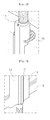
- As shown in
FIG. 1 , akey bar 14 is mounted directly on aframe body 10 by means of welding, and as shown inFIG. 2 , thekey bar 14 is mounted on theframe body 10 by means ofspring bars 12. - If the
key bar 14 is mounted directly on theframe body 10 by means of welding as shown inFIG. 1 , the stator is mounted in the state where thekey bar 14 is completely fixed to theframe body 10 after the welding, and in this case, accordingly, there is no difficulty in mounting a donut-shaped stator core bundle on the inner peripheral surface of theframe body 10. - However, if the
key bar 14 is mounted on theframe body 10 by means of thespring bars 12, as shown inFIG. 2 , the stator in the form of fan-shapedstator core sheets 1 as shown inFIG. 4 , not in the form of the donut-shaped stator core bundle as shown inFIG. 3 , should be manually mounted on theframe body 10, which causes many inconveniences in the installation. - In this case, as shown in
FIGS. 4 and5 , a plurality offirst fixing jigs 30 is disposed in the longitudinal direction of thekey bar 14 so as to align thekey bar 14 and thespring bars 12. In this case, if the donut-shaped stator core bundle enters theframe body 10, spatial interferences of thefirst fixing jigs 30 occurs. - So as to remove the above-mentioned problem, accordingly, the interference between the first fixing jigs and the stator core bundle should be removed, and the precise alignment of the key bars has to be achieved so that dove tails of the key bars are precisely fitted to key bar grooves of the stator core sheets in the state where no interference between the first fixing jigs and the stator core bundle occurs. Further, there is a need to provide a conveyor capable of conveying the stator core bundle laminated at the outside of the frame body to the inner peripheral surface of the frame body and mounting the stator core bundle thereon.
- Accordingly, in view of the above-mentioned problems occurring in the prior art, one or more exemplary embodiments provide a method for mounting a stator core on a generator and a generator using the same wherein when the stator core is mounted on the inner peripheral surface of a frame body of the generator on which spring bar type key bars are disposed, the stator core is mounted in the form of a donut-shaped stator core bundle thereon, thus reducing the manufacturing time and cost.
- To accomplish the above-mentioned object, according to an aspect of an exemplary embodiment, there is provided a method for mounting a stator core on a generator having key bars and spring bars disposed between the key bars and a frame body, the method including the key bar mounting operation of mounting the key bars on the spring bars pre-built on the frame body; the key bar alignment adjusting operation of adjusting the relative distance between the key bars and the spring bars to adjust the alignment of the key bars; and the donut-shaped stator core bundle mounting operation of fitting key bar grooves formed on the stator core to dove tails formed on the key bars when the stator core bundle is vertically descended to the interior of the frame body and mounted on the inner peripheral surface of the frame body.
- According to an exemplary embodiment, desirably, the key bar alignment adjusting operation includes the lower alignment adjusting operation of mounting at least one or more first fixing jigs on the space between one side of the lower portion of each key bar and one side of the lower portion of one side spring bar of the spring bars on which the key bar is disposed, so as to adjust the alignment of the lower sides of the key bars.
- According to an exemplary embodiment, desirably, the key bar alignment adjusting operation includes the upper alignment adjusting operation of mounting at least one or more second fixing jigs on the space between one side of the upper portion of each key bar and one side of the upper portion of one side spring bar of the spring bars on which the key bar is disposed, so as to adjust the alignment of the upper sides of the key bars.
- According to an exemplary embodiment, desirably, the key bar alignment adjusting operation includes the upper alignment fixing operation of mounting fixing wedges on the gaps between the top end of each key bar and the top end portions of the spring bars on which the key bar is disposed, so as to fix the alignment of the upper sides of the key bars adjusted by means of the second fixing jigs.
- According to an exemplary embodiment, desirably, the method further includes the donut-shaped stator core bundle forming operation of laminating the stator core sheets at the outside of the frame body to form the donut-shaped stator core bundle, before the donut-shaped stator core bundle mounting operation.
- According to an exemplary embodiment desirably, in the donut-shaped stator core bundle forming operation, fan-shaped stator core sheets are connected in a circumferential direction to form a donut-shaped stator core sheet, and the donut-shaped stator core sheets are laminated to form a stator core lamination structure, wherein in the state where the stator core lamination structures are laminated on top of each other, spacing plates are mounted between the neighboring stator core lamination structures to provide space in which a cooling fluid moves from the inner peripheral side of the stator core toward the outer peripheral side of the stator core.
- According to an exemplary embodiment, desirably, each spacing plate has a plurality of spacing beams mounted circumferentially in given intervals to form cooling passages in the space therebetween.
- According to an exemplary embodiment, desirably, the stator core bundle in which the spacing plates are disposed has clamping grooves formed in given intervals on the outer peripheral surface thereof so as to fit clamping jigs of a conveyor thereto, and the spacing beams whose outer ends are located on the positions where the clamping grooves are formed have the outer ends shorter than those of the neighboring spacing beams, thus preventing the interference with the clamping jigs of the conveyor.
- To accomplish the above-mentioned objects, according to an aspect of an exemplary embodiment, there is provided a generator including: a cylindrical frame body; a plurality of spring bars mounted on the inner peripheral surface of the frame body in a longitudinal direction of the frame body with given intervals in a circumferential direction of the frame body; and a plurality of key bars each disposed between the spring bars to support the stator core thereagainst, wherein the stator core has a plurality of stator core lamination structures each having donut-shaped stator core sheets laminated on top of each other and spacing plates mounted between the neighboring stator core lamination structures to provide space in which a cooling fluid moves from the inner peripheral side of the stator core toward the outer peripheral side of the stator core.
- According to an exemplary embodiment, desirably, the stator core lamination structures and the spacing plates have key bar grooves formed on the outer peripheral surfaces thereof in such a manner as to be fitted to the dove tails formed on the key bars and clamping grooves formed in at least one or more spaces between the neighboring key bar grooves, and the spacing beams whose outer ends are located on the positions where the clamping grooves are formed have the outer ends shorter than the
outer ends 61a of the neighboring spacing beams. - To accomplish the above-mentioned objects, according to an aspect of an exemplary embodiment, there is provided a stator core assembly including: a plurality of stator core lamination structures each having donut-shaped stator core sheets laminated on top of each other; and spacing plates mounted between the neighboring stator core lamination structures to provide space in which a cooling fluid moves from the inner peripheral side of the stator core toward the outer peripheral side of the stator core, each spacing plate having a plurality of spacing beams mounted circumferentially in given intervals to form cooling passages in the space therebetween.
- According to an exemplary embodiment, desirably, the stator core lamination structures and the spacing plates have key bar grooves formed on the outer peripheral surfaces thereof in such a manner as to be fitted to the dove tails formed on the key bars and clamping grooves formed in at least one or more spaces between the neighboring key bar grooves, and the spacing beams whose outer ends are located on the positions where the clamping grooves are formed have the outer ends shorter than the outer ends of the neighboring spacing beams.
- The above and/or other aspects of the disclosure will become apparent and more readily appreciated from the following detailed description of exemplary embodiments, taken in conjunction with the accompanying drawings, in which:
-
FIG. 1 is a perspective view showing a welding type key bar of the related art; -
FIG. 2 is a perspective view showing a spring bar type key bar of the related art; -
FIG. 3 is a sectional view showing a generator having spring bar type key bars mounted thereon of the related art; -
FIG. 4 is an exemplary view showing a method of the related art for mounting a stator core; -
FIG. 5 is a concept view of the related art showing the adjustment of the alignment between key bars and spring bars using first fixing jigs; -
FIG. 6 is a flow chart showing a method for mounting a stator core on a generator according to an exemplary embodiment; -
FIG. 7 is a flow chart showing the detailed operations of the key bar alignment adjusting operation according to an exemplary embodiment; and -
FIG. 8 is a flow chart showing a donut-shaped stator core bundle forming operation and a donut-shaped stator core bundle mounting operation according to an exemplary embodiment; -
FIG. 9 is a schematic view showing a method for mounting first fixing jigs according to an exemplary embodiment; -
FIGS. 10A and 10B are schematic views showing second fixing jigs and the mounted second fixing jigs according to an exemplary embodiment; -
FIG. 11 is a schematic view showing the installation of fixing wedges according to an exemplary embodiment; -
FIG. 12 is a perspective view showing stator core stacking structures, spacing plates, and a conveyor according to an exemplary embodiment; and -
FIGS. 13A and 13B are perspective views showing each spacing plate and spacing beams according to an exemplary embodiment - Hereinafter, an explanation on a method for mounting a stator core on a generator, a generator, and a stator core assembly according to exemplary embodiments will be in detail given with reference to the attached drawing.
- While this invention is illustrated and described in the exemplary embodiments, the device may be produced in many different configurations, forms, and characteristics. Those skilled in the art will envision many other possible variations within the scope of the inventive concept. In the description, similar reference numerals in the drawings have the same or similar functions as each other or to each other, and the thicknesses of the lines or the sizes of the components shown in the drawing may be magnified for the clarity and convenience of the description.
- As shown in
FIG. 6 , a method for mounting a stator core on a generator according to an exemplary embodiment mainly includes: a key bar mounting operation (S1), a key bar alignment adjusting operation (S2), and a donut-shaped stator core bundle mounting operation (S3). - First, the key bar mounting operation will be explained with reference to
FIG. 2 . As shown inFIG. 2 , a pair ofspring bars 12 is arranged on the inner peripheral surface of aframe body 10 in a longitudinal direction of theframe body 10, and akey bar 14 is disposed between the pair ofspring bars 12. - The key bar mounting operation according to the exemplary embodiment is conducted by using the
spring bars 12 as shown inFIG. 2 , which is different from the key bar mounting operation through the welding as shown inFIG. 1 . More particularly, the process for machining thekey bar 14 contains finish and rough milling for the precise alignment of thekey bar 14, which will be in detail explained later. - On the other hand, if the
key bar 14 is mounted on the inner peripheral surface of theframe body 10 by means of thespring bars 12 as shown inFIG.2 , the stator core should be inconveniently disposed manually thereon in the form of a fan-shapedstator core sheet 1, not in the form of a donut-shaped stator core bundle, as shown inFIGS.3 and4 . - As shown in
FIGS. 4 and5 , a plurality offirst fixing jigs 30 are disposed traversely with respect to thekey bar 14 so as to align thekey bar 14 and thespring bars 12. In this case, one end of eachfirst fixing jig 30 supports the side surface of thekey bar 14, so that if the donut-shaped stator core bundle enters theframe body 10, spatial interference may occur. - So as to remove the above-mentioned problem, accordingly, the key bar alignment adjusting operation is needed. Hereinafter, the key bar alignment adjusting operation will be explained.
-
FIG. 7 is a flow chart showing detailed operations of the key bar alignment adjusting operation (S2) according to an exemplary embodiment. The key bar alignment adjusting operation is conducted so as to remove the interference of the stator core with a plurality of first fixing jigs 30 when the stator core is mounted on the inner peripheral surface of theframe body 10, while achieving the precise alignment of thekey bars 14 to allow the donut-shaped stator core bundle to be mounted integrally on the key bars 14. - The precise alignment of the
key bars 14 is needed because the stator core bundle should be conveyed and mounted integrally on thekey bars 14 in the state wherekey bar grooves 62 and 110 (SeeFIGS. 12 ,13A and 13B ) formed on the outer periphery of the stator core are fitted to dove tails 14a (SeeFIG. 10A ) formed on the key bars 14. - As shown in
FIG. 7 , the key bar alignment adjusting operation is divided into a lower alignment adjusting operation (S21), a upper alignment adjusting operation (S22), and a upper alignment fixing operation (S23). Hereinafter, the above operations will be sequentially described. - First,
FIG. 9 is a schematic view showing the installation relation among thekey bars 14, the spring bars 12 on which thekey bar 14 is disposed, and the first fixing jigs 30. - In the related art, as shown in
FIG. 4 , about three hundred thirty (330) first fixingjigs 30 are mounted over the lower, intermediate and upper sides of thekey bars 14 so as to adjust the whole alignment of the key bars 14. - In this case, as mentioned above, the donut-shaped stator core bundle enters the
frame body 10 from the upper sides of thekey bars 14, the interference of the stator core bundle with the first fixing jigs 30 arranged on the upper sides of thekey bars 14 occurs. Such problem also occurs when a semi-circular stator core bundle or a fan-shaped stator core bundle having a given angle enters theframe body 10. In case of the generator having the spring bar type key bars, accordingly, the fan-shaped stator core sheets should be mounted one by one, as shown inFIG. 4 . - According to the exemplary embodiment, as shown in
FIG. 9 , the first fixing jigs 30 are disposed just on the lower portions of thekey bars 14 with respect to theframe body 10 standing vertically, so that the interference in entry can be basically removed. - On the other hand, as shown in
FIG. 5 , each first fixingjig 30 is a device that adjusts a relative distance, and the first fixingjig 30 has acenter shaft 33 on which a screw thread is formed and supports 31 disposed on both ends of thecenter shaft 33. Further, the first fixingjig 30 has ahexagonal adjustor 32 disposed on the center of thecenter shaft 33, to which a wrench is fitted, so that theadjustor 32 rotates to adjust the relative distance with thesupports 31. Finally, the relative distance between one side of the lower portion of eachkey bar 14 and one side of the lower portion of oneside spring bar 12 of the spring bars 12 on which thekey bar 14 is disposed is adjusted to adjust the alignment of the lower side of thekey bar 14. - In the exemplary embodiment, the adjustment of the alignment of the upper (and the intermediate) side of the
key bar 14 is additionally needed, which is conducted with second fixing jigs 40 as shown inFIGS. 10A and 10B . - As shown in
FIGS. 10A and 10B , the second fixing jigs 40 adjust the alignment between one side of the upper portion of thekey bar 14 and one side of the upper portion of oneside spring bar 12 of the spring bars 12 on which thekey bar 14 is disposed. - In more detail, each second fixing
jig 40 has a pair ofsupports 41 fixed vertically to the side surfaces of the spring bars 12 and aconnection shaft 42 horizontally connecting the end portions of thesupports 41 with each other. Theconnection shaft 42 has a through hole formed thereon, around which a screw thread is formed vertically, and thesecond fixing jig 40 further has an adjustingshaft 43 fitted to the through hole in such a manner as to move vertically, the adjustingshaft 43 having a screw thread formed thereon to correspond to the screw thread formed on the through hole. - One end of the adjusting
shaft 43 is provided with acontact portion 44 which is brought into contact with the dove tail 14a of thekey bar 14, and the other end thereof is provided with ahexagonal head 45 to which a wrench is fitted. As thehead 45 rotates, the adjustingshaft 43 rotates, and accordingly, thecontact portion 44 formed on one end of the adjustingshaft 43 moves forward and backward, thus adjusting the alignment of thekey bar 14. - The second fixing jigs 40 protrude forward from the
key bars 14, and accordingly, it is obvious that if the donut-shaped stator core bundle enters, the interference of the second fixing jigs 40 occurs. So as to remove such interference, desirably, the upper alignment adjusted in the upper alignment adjusting operation should be fixed through the upper alignment fixing operation, and after the upper alignment is fixed, the second fixing jigs 40 should be finally removed. - Hereinafter, the upper alignment fixing operation (S23) will be in detail explained with reference to
FIG. 11 . - As shown in
FIG. 11 , the upper alignment fixing operation is conducted wherein fixingwedges 50 are disposed on the gaps between the top end of thekey bar 14 and the top end portions of the spring bars 12, so as to fix the alignment of the upper side of thekey bar 14 adjusted by means of the second fixing jigs 40. - The gaps between the spring bars 12 and the
key bar 14 are necessarily generated, and the fixingwedges 50, which become increased in thickness as they go toward the upper portions thereof, are fitted to the gaps, so that the alignment of the upper side of thekey bar 14 adjusted by means of the second fixing jigs 40 can be maintained. - The fixing
wedges 50 are fitted to the top end portions of the spring bars 12 and thekey bar 14, not to the front surfaces thereof, so that even if the donut-shaped stator core bundle enters, no interference therebetween occurs. - According to an exemplary embodiment, on the other hand, the alignment adjustment is simply conducted, and therefore, it is very important to ensure the straightness of the
key bar 14 when thekey bar 14 is machined before the installation. According to the related art, after thekey bar 14 is roughly milled, the finish milling for the dove tail 14a is just conducted, which causes the straightness of thekey bar 14 to be deformed over 3 mm. - So as to ensure the straightness of the
key bar 14, according to the exemplary embodiment, the rough milling for the machining of the whole shape of thekey bar 14 is first conducted, and after fairing is adjusted again, the fine finish machining of the dove tail 14a is conducted. According to the exemplary embodiment, the final deformation in the straightness of thekey bar 14 is less than 0.13 mm, which permits the method for mounting the stator core on the generator according to the exemplary embodiment to be carried out. - On the other hand, the rough milling and the finish milling are divided by roughness. Generally, the rough milling has the roughness of 1 µm Ra or more, the finish milling between about 0.5 µm Ra and 0.2 µm Ra, and the super finish milling 0.1 µm Ra or less.
- After the key bar alignment adjusting operation, the donut-shaped stator core bundle mounting operation (S3) is conducted wherein the donut-shaped stator core bundle pre-laminated at the outside of the
frame body 10 is vertically descended inside theframe body 10 and mounted on the inner peripheral surface thereof, and next, thekey bar grooves - The donut-shaped stator core bundle is just one example, and accordingly, the
stator core sheets 1 in a given unit, that is, in a semi-circular shape, a fan shape having a given angle, and the like are laminated at the outside of theframe body 10, and the laminated stator core sheets are conveyed together and mounted on the inner peripheral surface of theframe body 10. The given angle in the given unit means that if the center angle of onestator core sheet 1 is X, the given angle becomes 2X, 3X or the like. That is, the donut-shaped stator core means the stator core pre-laminated to 360°, and the semi-circular-shaped stator core means the stator core pre-laminated to 180°. - Hereinafter, the donut-shaped stator core bundle mounting operation (S3) will be described with respect to the donut-shaped stator core bundle pre-laminated to 360°.
- Before the donut-shaped stator core bundle mounting operation, of course, a donut-shaped stator core bundle forming operation is needed wherein the stator core sheets are laminated one by one at to form the donut-shaped stator core bundle.
-
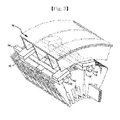
FIG. 12 shows the donut-shaped stator core bundle. - In the donut-shaped stator core bundle forming operation (S31), first, the fan-shaped single
stator core sheets 1 are connected in a circumferential direction to form a donut-shaped stator core sheet. Next, the donut-shaped single stator core sheets are laminated to form a statorcore lamination structure 100. - The stator
core lamination structures 100 are laminated on top of each other, andspacing plates 60 are desirably mounted between the neighboring statorcore lamination structures 100 to provide space in which a cooling fluid moves from the inner peripheral side of the stator core toward the outer peripheral side of the stator core. As shown inFIG. 12 , thespacing plates 60 are disposed alternately to the statorcore lamination structures 100 to provide the space in given intervals. - Further, as shown in
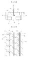
FIGS. 13A and 13B , each spacingplate 60 has a plurality ofspacing beams 61 mounted circumferentially in given intervals to form cooling passages in the space therebetween. In this case, along the cooling passages, generally, hydrogen moves from the inner side of the stator in which a rotor is disposed to a housing. - The stator core bundle in which the
spacing plates 60 are disposed has clampinggrooves 63 and 120 formed in given intervals on the outer peripheral surface thereof so as to fit clampingjigs 210 of aconveyor 200 thereto. - As shown in
FIG. 13B , the spacing beams 61 whose outer ends 61a are located on the positions where the clampinggrooves 63 are formed have the outer ends 61a shorter than those of the neighboring spacing beams 61, thus preventing the interference with the clampingjigs 210 of theconveyor 200. The spacing beams 61 extended to the outer peripheral edge of thespacing plate 60 as shown inFIG. 13A serve to support wood wedges, but since the outer ends 61a of the spacing beams 61 are extended to the outer peripheral edge of thespacing plate 60, the interference of the clampingjigs 210 occurs. - So as to solve the problem, as shown in
FIG. 13B , the spacing beams 61 whose outer ends 61a are located on the positions where the clampinggrooves 63 are formed have the outer ends 61a shorter than those of the neighboring spacing beams 61, and further, the wedges for assembly are desirably supported by means of the application of silicone. - Hereinafter, an explanation on a generator and a stator core assembly according to an exemplary embodiment will be given. An explanation on the repeated contents in the description will be avoided for the brevity of the description, and the characteristics of the generator and the stator core assembly according to the exemplary embodiment will be explained.
- According to the exemplary embodiment, the generator includes the
cylindrical frame body 10, the plurality of spring bars 12 mounted on the inner peripheral surface of theframe body 10 in a longitudinal direction of theframe body 10 with given intervals in a circumferential direction of theframe body 10, and the plurality ofkey bars 14 each disposed between the spring bars 12 to support the stator core thereagainst. - The stator core includes the plurality of stator
core lamination structures 100 each having the donut-shaped stator core sheets laminated on top of each other. Further, the stator core includes thespacing plates 60 mounted between the neighboring statorcore lamination structures 100 to provide the space in which a cooling fluid moves from the inner peripheral side of the stator core toward the outer peripheral side of the stator core. As described above, the statorcore lamination structures 100 and thespacing plates 60 have thekey bar grooves key bars 14 and the clampinggrooves 63 and 120 formed in at least one or more spaces between the neighboringkey bar grooves - The spacing beams 61 whose outer ends 61a are located on the positions where the clamping
grooves 63 are formed desirably have the outer ends 61 a shorter than those of the neighboring spacing beams 61. - The formation of the short outer ends 61a of the spacing beams 61 prevents the spatial interference with the spacing beams 61 from occurring when the clamping
jigs 210 are mounted on the clampinggrooves 63 for the conveyance. - According to the exemplary embodiment, on the other hand, the stator core assembly includes the plurality of stator
core lamination structures 100 each having the donut-shaped stator core sheets laminated on top of each other and thespacing plates 60 mounted between the neighboring statorcore lamination structures 100 to provide the space in which a cooling fluid moves from the inner peripheral side of the stator core toward the outer peripheral side of the stator core. - Further, each spacing
plate 60 has the plurality ofspacing beams 61 mounted circumferentially in given intervals to form cooling passages in the space therebetween. - Furthermore, the stator
core lamination structures 100 and thespacing plates 60 have thekey bar grooves key bars 14 and the clampinggrooves 63 and 120 formed in at least one or more spaces between the neighboringkey bar grooves frame body 10. In this case, the spacing beams 61 whose outer ends 61a are located on the positions where the clampinggrooves 63 are formed desirably have the outer ends 61 a shorter than those of the neighboring spacing beams 61. - As mentioned above, the method for mounting the stator core on the generator according to the exemplary embodiment is capable of mounting the donut-shaped stator core bundle pre-laminated in a given unit at the outside of the frame body on the inner peripheral surface of the frame body, not mounting the stator core in a unit of a sheet in a manual operation in the convention practice thereon, thus achieving greater working efficiencies than the conventional method.
- In the description of the exemplary, the position relations used therein has been explained with reference to the attached drawings, and according to aspects of the exemplary embodiment, the position relations may be varied.
- Further, all of terms inclusive of technical or scientific terms used therein have the same meaning as will be understood by those skilled in the art. Therefore, they should be defined on the basis of the whole scope of the inventive concept.
- While exemplary embodiments have been particularly shown and described above, it would be appreciated by those skilled in the art that various changes may be made therein without departing from the scope and spirit of the present inventive concept as defined by the following claims.
Claims (15)
- A method for mounting a stator core on a generator, the generator having key bars (14) and spring bars (12) disposed between the key bars (14) and a frame body (10), the method comprising:pre-laminating stator core sheets to form a stator core bundle in a given unit; andconveying the stator core bundle laminated in the given unit to mount the stator core bundle on the inner peripheral surface of the frame body (10).
- The method according to claim 1, wherein the stator core bundle is pre-laminated at the outside the frame body (10).
- The method according to claim 1 or 2, wherein the stator core bundle has a shape of a donut, and the donut-shaped stator core bundle is conveyed and mounted on an inner peripheral surface of the frame body (10).
- The method according to any one of the preceding claims, wherein the conveying the stator core bundle to mount the stator core bundle having a donut shape comprises fitting key bar grooves (62, 110) formed on the stator core to dove tails (14a) formed on the key bars (14) when the stator core bundle is vertically descended to an interior of the frame body (10) and mounted on an inner peripheral surface of the frame body (10).
- The method according to any one of the preceding claims, further comprising:mounting the key bars (14) on the spring bars (12) pre-built on the frame body (10); andadjusting a relative distance between the key bars (14) and the spring bars (12) to adjust the alignment of the key bars (14).
- The method according to claim 5, wherein the adjusting the relative distance comprises mounting at least one or more first fixing jigs (30) on the space between one side of the lower portion of each key bar (14) and one side of the lower portion of one side spring bar (12) of the spring bars (12) on which the key bar (14) is disposed, so as to adjust the alignment of the lower sides of the key bars (14).
- The method according to claim 6, wherein the adjusting the relative distance further comprises mounting at least one or more second fixing jigs (40) on the space between one side of an upper portion of each key bar (14) and one side of the upper portion of one side spring bar (12) of the spring bars (12) on which the key bar (14) is disposed, so as to adjust the alignment of upper sides of the key bars (14).
- The method according to claim 7, wherein the adjusting the relative distance further comprises mounting fixing wedges (50) on gaps between a top end of each key bar (14) and top end portions of the spring bars (12) on which the key bar (14) is disposed, so as to fix the alignment of the upper sides of the key bars (14) adjusted by means of the second fixing jigs (40).
- The method according to claim 4, further comprising laminating the stator core sheets at the outside of the frame body (10) to form a donut-shaped stator core bundle, before mounting the donut-shaped stator core bundle.
- The method according to claim 9, wherein in the forming the donut-shaped stator core bundle, fan-shaped stator core sheets are connected in a circumferential direction to form a plurality of donut-shaped stator core sheets, and the donut-shaped stator core sheets are laminated to form a stator core lamination structure (100),
wherein in the state where stator core lamination structures (100) are laminated on top of each other, spacing plates (60) are mounted between neighboring stator core lamination structures (100) to provide space in which a cooling fluid moves from the inner peripheral side of the stator core toward an outer peripheral side of the stator core. - The method according to claim 10, wherein each spacing plate (60) comprises a plurality of spacing beams (61) mounted circumferentially in given intervals to form cooling passages in the space therebetween.
- The method according to claim 11, wherein the stator core bundle in which the spacing plates (60) are disposed comprises clamping grooves (63, 120) formed in given intervals on an outer peripheral surface thereof so as to fit clamping jigs (210) of a conveyor (200) thereto, and the spacing beams (61) in which outer ends (61a) are located on the positions where the clamping grooves (63) are formed have the outer ends (61a) shorter than the outer ends of the neighboring spacing beams (61), thus preventing the interference with the clamping jigs (210) of the conveyor (200).
- A generator comprising:a cylindrical frame body (10);a plurality of spring bars (12) mounted on an inner peripheral surface of the frame body (10) in a longitudinal direction of the frame body (10) with given intervals in a circumferential direction of the frame body (10); anda plurality of key bars (14), each of the key bars (14) disposed between the spring bars (12) to support the stator core thereagainst,wherein the stator core comprises a plurality of stator core lamination structures (100), each of the lamination structures (100) comprising donut-shaped stator core sheets laminated on top of each other and spacing plates (60) mounted between neighboring stator core lamination structures (100) to provide a space in which a cooling fluid moves from the inner peripheral side of the stator core toward an outer peripheral side of the stator core.
- The generator according to claim 13, wherein each spacing plate (60) has a plurality of spacing beams (61) mounted circumferentially in given intervals to form cooling passages in the space therebetween.
- The generator according to claim 13 or 14, wherein the stator core lamination structures (100) and the spacing plates (60) have key bar grooves (62, 110) formed on outer peripheral surfaces thereof in such a manner as to be fitted to dove tails (14a) formed on the key bars (14) and clamping grooves (62, 110) formed in at least one or more spaces between neighboring key bar grooves (62, 110), and the spacing beams in which outer ends are located on the positions where the clamping grooves (63) are formed have the outer ends shorter than the outer ends of neighboring spacing beams (61), thus preventing the interference with the clamping jigs of the conveyor.
Applications Claiming Priority (1)
| Application Number | Priority Date | Filing Date | Title |
|---|---|---|---|
| KR1020140006334A KR101526297B1 (en) | 2014-01-17 | 2014-01-17 | Stator core installation method of generator, a generator thereof and a stator core assembly |
Publications (3)
| Publication Number | Publication Date |
|---|---|
| EP2897255A2 true EP2897255A2 (en) | 2015-07-22 |
| EP2897255A3 EP2897255A3 (en) | 2016-06-15 |
| EP2897255B1 EP2897255B1 (en) | 2019-07-31 |
Family
ID=52347201
Family Applications (1)
| Application Number | Title | Priority Date | Filing Date |
|---|---|---|---|
| EP15151303.3A Active EP2897255B1 (en) | 2014-01-17 | 2015-01-15 | Method for mounting stator core on generator and generator and stator core assembly using the same |
Country Status (4)
| Country | Link |
|---|---|
| US (1) | US9812910B2 (en) |
| EP (1) | EP2897255B1 (en) |
| KR (1) | KR101526297B1 (en) |
| CN (1) | CN104795942B (en) |
Family Cites Families (9)
| Publication number | Priority date | Publication date | Assignee | Title |
|---|---|---|---|---|
| US4891540A (en) * | 1988-11-01 | 1990-01-02 | Westinghouse Electric Corp. | Generator core support system |
| US5869912A (en) * | 1997-07-25 | 1999-02-09 | General Electric Co. | Direct-cooled dynamoelectric machine stator core with enhanced heat transfer capability |
| JP2000078781A (en) * | 1998-09-01 | 2000-03-14 | Fuji Electric Co Ltd | Stator core for electric machine |
| US6242825B1 (en) * | 1998-11-25 | 2001-06-05 | Hitachi, Ltd. | Electric rotating machine with reduced thickness and volume of insulation |
| US6628027B2 (en) | 2000-12-18 | 2003-09-30 | Siemens Westinghouse Power Corporation | Power generation system including an apparatus for attaching a generator stator core to frame support and associated methods |
| JP3811405B2 (en) * | 2002-01-11 | 2006-08-23 | 三菱電機株式会社 | Stator core supply device for rotating electrical machine and stator core stacking device for rotating electrical machine |
| KR100841963B1 (en) * | 2007-01-19 | 2008-06-27 | 두산중공업 주식회사 | Fastener for preventing welding distortion of key bar for generator |
| US8040014B2 (en) * | 2009-11-20 | 2011-10-18 | General Electric Company | Stator core suspension and related spring bar |
| US8319405B2 (en) * | 2010-08-20 | 2012-11-27 | Siemens Energy, Inc. | Methods and apparatuses for attaching a stator core to a generator frame |
-
2014
- 2014-01-17 KR KR1020140006334A patent/KR101526297B1/en active IP Right Grant
- 2014-11-10 CN CN201410645052.4A patent/CN104795942B/en active Active
-
2015
- 2015-01-08 US US14/592,553 patent/US9812910B2/en active Active
- 2015-01-15 EP EP15151303.3A patent/EP2897255B1/en active Active
Non-Patent Citations (1)
| Title |
|---|
| None |
Also Published As
| Publication number | Publication date |
|---|---|
| US20150207369A1 (en) | 2015-07-23 |
| US9812910B2 (en) | 2017-11-07 |
| CN104795942A (en) | 2015-07-22 |
| EP2897255A3 (en) | 2016-06-15 |
| EP2897255B1 (en) | 2019-07-31 |
| CN104795942B (en) | 2018-10-23 |
| KR101526297B1 (en) | 2015-06-05 |
Similar Documents
| Publication | Publication Date | Title |
|---|---|---|
| US9627950B2 (en) | Method of servicing a power generator | |
| KR101501862B1 (en) | Manufacturing method for helical core for rotating electrical machine and manufacturing device for helical core for rotating electrical machine | |
| KR20090041300A (en) | Rotor of rotary electric machine and manufacturing method of the same | |
| KR20140133543A (en) | Turbine generator stator core attachment technique | |
| JP6096460B2 (en) | Coil manufacturing system | |
| JP2017108578A (en) | Stator laminated iron core and manufacturing method of the same | |
| US5043616A (en) | Induction motor mounted on bolted legs and end plates | |
| US20130049520A1 (en) | Stator structure and method for manufacturing the same | |
| US20150135518A1 (en) | Manufacturing a Stator For A Rotating Electrical Machine | |
| CN105449878A (en) | Motor stator structure and motor | |
| US9812910B2 (en) | Method for mounting stator core on generator assembly using the same | |
| CN111541314A (en) | Stator core of motor and motor | |
| JP6705774B2 (en) | Magnet plate mounting structure | |
| EP3402044A1 (en) | Magnet module and method of manufacturing same | |
| JP2016067085A (en) | Assembling method of dynamo-electric machine | |
| WO2021007804A1 (en) | Stator assembly and stator for motor | |
| US9806568B2 (en) | Stator/rotor lamination sheet for stator/rotor laminations of generators and electric motors, stator/rotor lamination with such a stator/rotor lamination sheet as well as method for manufacturing a stator/rotor lamination sheet | |
| JP2014045641A (en) | Stator core of dynamo-electric machine | |
| KR101486751B1 (en) | The superconduction coil assembly for module | |
| EP2755307B1 (en) | Method and device for manufacturing a laminated stator core | |
| JP6042360B2 (en) | Motor with cooling jacket | |
| CN108494126A (en) | Rotor, motor and wind power generating set | |
| JP6898886B2 (en) | Rotating machine and stator damping structure | |
| WO2023119931A1 (en) | Method for manufacturing stator and device for manufacturing stator | |
| KR100816040B1 (en) | Method for manufacturing stator assembly of generator |
Legal Events
| Date | Code | Title | Description |
|---|---|---|---|
| PUAI | Public reference made under article 153(3) epc to a published international application that has entered the european phase |
Free format text: ORIGINAL CODE: 0009012 |
|
| 17P | Request for examination filed |
Effective date: 20150115 |
|
| AK | Designated contracting states |
Kind code of ref document: A2 Designated state(s): AL AT BE BG CH CY CZ DE DK EE ES FI FR GB GR HR HU IE IS IT LI LT LU LV MC MK MT NL NO PL PT RO RS SE SI SK SM TR |
|
| AX | Request for extension of the european patent |
Extension state: BA ME |
|
| PUAL | Search report despatched |
Free format text: ORIGINAL CODE: 0009013 |
|
| AK | Designated contracting states |
Kind code of ref document: A3 Designated state(s): AL AT BE BG CH CY CZ DE DK EE ES FI FR GB GR HR HU IE IS IT LI LT LU LV MC MK MT NL NO PL PT RO RS SE SI SK SM TR |
|
| AX | Request for extension of the european patent |
Extension state: BA ME |
|
| RIC1 | Information provided on ipc code assigned before grant |
Ipc: H02K 1/18 20060101AFI20160510BHEP Ipc: H02K 1/20 20060101ALI20160510BHEP |
|
| RBV | Designated contracting states (corrected) |
Designated state(s): AL AT BE BG CH CY CZ DE DK EE ES FI FR GB GR HR HU IE IS IT LI LT LU LV MC MK MT NL NO PL PT RO RS SE SI SK SM TR |
|
| STAA | Information on the status of an ep patent application or granted ep patent |
Free format text: STATUS: EXAMINATION IS IN PROGRESS |
|
| 17Q | First examination report despatched |
Effective date: 20171120 |
|
| GRAP | Despatch of communication of intention to grant a patent |
Free format text: ORIGINAL CODE: EPIDOSNIGR1 |
|
| STAA | Information on the status of an ep patent application or granted ep patent |
Free format text: STATUS: GRANT OF PATENT IS INTENDED |
|
| INTG | Intention to grant announced |
Effective date: 20190221 |
|
| RIN1 | Information on inventor provided before grant (corrected) |
Inventor name: OH, SE WOOK Inventor name: KWAK, MOOSEOK Inventor name: LEE, SANG MAN |
|
| RAP1 | Party data changed (applicant data changed or rights of an application transferred) |
Owner name: DOOSAN HEAVY INDUSTRIES & CONSTRUCTION CO., LTD. |
|
| GRAS | Grant fee paid |
Free format text: ORIGINAL CODE: EPIDOSNIGR3 |
|
| GRAA | (expected) grant |
Free format text: ORIGINAL CODE: 0009210 |
|
| STAA | Information on the status of an ep patent application or granted ep patent |
Free format text: STATUS: THE PATENT HAS BEEN GRANTED |
|
| AK | Designated contracting states |
Kind code of ref document: B1 Designated state(s): AL AT BE BG CH CY CZ DE DK EE ES FI FR GB GR HR HU IE IS IT LI LT LU LV MC MK MT NL NO PL PT RO RS SE SI SK SM TR |
|
| REG | Reference to a national code |
Ref country code: CH Ref legal event code: EP Ref country code: GB Ref legal event code: FG4D |
|
| REG | Reference to a national code |
Ref country code: AT Ref legal event code: REF Ref document number: 1161979 Country of ref document: AT Kind code of ref document: T Effective date: 20190815 |
|
| REG | Reference to a national code |
Ref country code: IE Ref legal event code: FG4D |
|
| REG | Reference to a national code |
Ref country code: DE Ref legal event code: R096 Ref document number: 602015034631 Country of ref document: DE |
|
| REG | Reference to a national code |
Ref country code: NL Ref legal event code: MP Effective date: 20190731 |
|
| REG | Reference to a national code |
Ref country code: LT Ref legal event code: MG4D |
|
| REG | Reference to a national code |
Ref country code: AT Ref legal event code: MK05 Ref document number: 1161979 Country of ref document: AT Kind code of ref document: T Effective date: 20190731 |
|
| PG25 | Lapsed in a contracting state [announced via postgrant information from national office to epo] |
Ref country code: PT Free format text: LAPSE BECAUSE OF FAILURE TO SUBMIT A TRANSLATION OF THE DESCRIPTION OR TO PAY THE FEE WITHIN THE PRESCRIBED TIME-LIMIT Effective date: 20191202 Ref country code: LT Free format text: LAPSE BECAUSE OF FAILURE TO SUBMIT A TRANSLATION OF THE DESCRIPTION OR TO PAY THE FEE WITHIN THE PRESCRIBED TIME-LIMIT Effective date: 20190731 Ref country code: SE Free format text: LAPSE BECAUSE OF FAILURE TO SUBMIT A TRANSLATION OF THE DESCRIPTION OR TO PAY THE FEE WITHIN THE PRESCRIBED TIME-LIMIT Effective date: 20190731 Ref country code: BG Free format text: LAPSE BECAUSE OF FAILURE TO SUBMIT A TRANSLATION OF THE DESCRIPTION OR TO PAY THE FEE WITHIN THE PRESCRIBED TIME-LIMIT Effective date: 20191031 Ref country code: AT Free format text: LAPSE BECAUSE OF FAILURE TO SUBMIT A TRANSLATION OF THE DESCRIPTION OR TO PAY THE FEE WITHIN THE PRESCRIBED TIME-LIMIT Effective date: 20190731 Ref country code: NL Free format text: LAPSE BECAUSE OF FAILURE TO SUBMIT A TRANSLATION OF THE DESCRIPTION OR TO PAY THE FEE WITHIN THE PRESCRIBED TIME-LIMIT Effective date: 20190731 Ref country code: NO Free format text: LAPSE BECAUSE OF FAILURE TO SUBMIT A TRANSLATION OF THE DESCRIPTION OR TO PAY THE FEE WITHIN THE PRESCRIBED TIME-LIMIT Effective date: 20191031 Ref country code: HR Free format text: LAPSE BECAUSE OF FAILURE TO SUBMIT A TRANSLATION OF THE DESCRIPTION OR TO PAY THE FEE WITHIN THE PRESCRIBED TIME-LIMIT Effective date: 20190731 Ref country code: FI Free format text: LAPSE BECAUSE OF FAILURE TO SUBMIT A TRANSLATION OF THE DESCRIPTION OR TO PAY THE FEE WITHIN THE PRESCRIBED TIME-LIMIT Effective date: 20190731 |
|
| PG25 | Lapsed in a contracting state [announced via postgrant information from national office to epo] |
Ref country code: IS Free format text: LAPSE BECAUSE OF FAILURE TO SUBMIT A TRANSLATION OF THE DESCRIPTION OR TO PAY THE FEE WITHIN THE PRESCRIBED TIME-LIMIT Effective date: 20191130 Ref country code: LV Free format text: LAPSE BECAUSE OF FAILURE TO SUBMIT A TRANSLATION OF THE DESCRIPTION OR TO PAY THE FEE WITHIN THE PRESCRIBED TIME-LIMIT Effective date: 20190731 Ref country code: RS Free format text: LAPSE BECAUSE OF FAILURE TO SUBMIT A TRANSLATION OF THE DESCRIPTION OR TO PAY THE FEE WITHIN THE PRESCRIBED TIME-LIMIT Effective date: 20190731 Ref country code: ES Free format text: LAPSE BECAUSE OF FAILURE TO SUBMIT A TRANSLATION OF THE DESCRIPTION OR TO PAY THE FEE WITHIN THE PRESCRIBED TIME-LIMIT Effective date: 20190731 Ref country code: GR Free format text: LAPSE BECAUSE OF FAILURE TO SUBMIT A TRANSLATION OF THE DESCRIPTION OR TO PAY THE FEE WITHIN THE PRESCRIBED TIME-LIMIT Effective date: 20191101 Ref country code: AL Free format text: LAPSE BECAUSE OF FAILURE TO SUBMIT A TRANSLATION OF THE DESCRIPTION OR TO PAY THE FEE WITHIN THE PRESCRIBED TIME-LIMIT Effective date: 20190731 |
|
| PG25 | Lapsed in a contracting state [announced via postgrant information from national office to epo] |
Ref country code: TR Free format text: LAPSE BECAUSE OF FAILURE TO SUBMIT A TRANSLATION OF THE DESCRIPTION OR TO PAY THE FEE WITHIN THE PRESCRIBED TIME-LIMIT Effective date: 20190731 |
|
| PG25 | Lapsed in a contracting state [announced via postgrant information from national office to epo] |
Ref country code: RO Free format text: LAPSE BECAUSE OF FAILURE TO SUBMIT A TRANSLATION OF THE DESCRIPTION OR TO PAY THE FEE WITHIN THE PRESCRIBED TIME-LIMIT Effective date: 20190731 Ref country code: DK Free format text: LAPSE BECAUSE OF FAILURE TO SUBMIT A TRANSLATION OF THE DESCRIPTION OR TO PAY THE FEE WITHIN THE PRESCRIBED TIME-LIMIT Effective date: 20190731 Ref country code: IT Free format text: LAPSE BECAUSE OF FAILURE TO SUBMIT A TRANSLATION OF THE DESCRIPTION OR TO PAY THE FEE WITHIN THE PRESCRIBED TIME-LIMIT Effective date: 20190731 Ref country code: EE Free format text: LAPSE BECAUSE OF FAILURE TO SUBMIT A TRANSLATION OF THE DESCRIPTION OR TO PAY THE FEE WITHIN THE PRESCRIBED TIME-LIMIT Effective date: 20190731 Ref country code: PL Free format text: LAPSE BECAUSE OF FAILURE TO SUBMIT A TRANSLATION OF THE DESCRIPTION OR TO PAY THE FEE WITHIN THE PRESCRIBED TIME-LIMIT Effective date: 20190731 |
|
| PG25 | Lapsed in a contracting state [announced via postgrant information from national office to epo] |
Ref country code: CZ Free format text: LAPSE BECAUSE OF FAILURE TO SUBMIT A TRANSLATION OF THE DESCRIPTION OR TO PAY THE FEE WITHIN THE PRESCRIBED TIME-LIMIT Effective date: 20190731 Ref country code: IS Free format text: LAPSE BECAUSE OF FAILURE TO SUBMIT A TRANSLATION OF THE DESCRIPTION OR TO PAY THE FEE WITHIN THE PRESCRIBED TIME-LIMIT Effective date: 20200224 Ref country code: SK Free format text: LAPSE BECAUSE OF FAILURE TO SUBMIT A TRANSLATION OF THE DESCRIPTION OR TO PAY THE FEE WITHIN THE PRESCRIBED TIME-LIMIT Effective date: 20190731 Ref country code: SM Free format text: LAPSE BECAUSE OF FAILURE TO SUBMIT A TRANSLATION OF THE DESCRIPTION OR TO PAY THE FEE WITHIN THE PRESCRIBED TIME-LIMIT Effective date: 20190731 |
|
| REG | Reference to a national code |
Ref country code: DE Ref legal event code: R097 Ref document number: 602015034631 Country of ref document: DE |
|
| PLBE | No opposition filed within time limit |
Free format text: ORIGINAL CODE: 0009261 |
|
| STAA | Information on the status of an ep patent application or granted ep patent |
Free format text: STATUS: NO OPPOSITION FILED WITHIN TIME LIMIT |
|
| PG2D | Information on lapse in contracting state deleted |
Ref country code: IS |
|
| PG25 | Lapsed in a contracting state [announced via postgrant information from national office to epo] |
Ref country code: IS Free format text: LAPSE BECAUSE OF FAILURE TO SUBMIT A TRANSLATION OF THE DESCRIPTION OR TO PAY THE FEE WITHIN THE PRESCRIBED TIME-LIMIT Effective date: 20191030 |
|
| 26N | No opposition filed |
Effective date: 20200603 |
|
| PG25 | Lapsed in a contracting state [announced via postgrant information from national office to epo] |
Ref country code: MC Free format text: LAPSE BECAUSE OF FAILURE TO SUBMIT A TRANSLATION OF THE DESCRIPTION OR TO PAY THE FEE WITHIN THE PRESCRIBED TIME-LIMIT Effective date: 20190731 Ref country code: SI Free format text: LAPSE BECAUSE OF FAILURE TO SUBMIT A TRANSLATION OF THE DESCRIPTION OR TO PAY THE FEE WITHIN THE PRESCRIBED TIME-LIMIT Effective date: 20190731 |
|
| REG | Reference to a national code |
Ref country code: CH Ref legal event code: PL |
|
| GBPC | Gb: european patent ceased through non-payment of renewal fee |
Effective date: 20200115 |
|
| REG | Reference to a national code |
Ref country code: BE Ref legal event code: MM Effective date: 20200131 |
|
| PG25 | Lapsed in a contracting state [announced via postgrant information from national office to epo] |
Ref country code: LU Free format text: LAPSE BECAUSE OF NON-PAYMENT OF DUE FEES Effective date: 20200115 Ref country code: GB Free format text: LAPSE BECAUSE OF NON-PAYMENT OF DUE FEES Effective date: 20200115 |
|
| PG25 | Lapsed in a contracting state [announced via postgrant information from national office to epo] |
Ref country code: BE Free format text: LAPSE BECAUSE OF NON-PAYMENT OF DUE FEES Effective date: 20200131 Ref country code: CH Free format text: LAPSE BECAUSE OF NON-PAYMENT OF DUE FEES Effective date: 20200131 Ref country code: LI Free format text: LAPSE BECAUSE OF NON-PAYMENT OF DUE FEES Effective date: 20200131 |
|
| PG25 | Lapsed in a contracting state [announced via postgrant information from national office to epo] |
Ref country code: IE Free format text: LAPSE BECAUSE OF NON-PAYMENT OF DUE FEES Effective date: 20200115 |
|
| PG25 | Lapsed in a contracting state [announced via postgrant information from national office to epo] |
Ref country code: MT Free format text: LAPSE BECAUSE OF FAILURE TO SUBMIT A TRANSLATION OF THE DESCRIPTION OR TO PAY THE FEE WITHIN THE PRESCRIBED TIME-LIMIT Effective date: 20190731 Ref country code: CY Free format text: LAPSE BECAUSE OF FAILURE TO SUBMIT A TRANSLATION OF THE DESCRIPTION OR TO PAY THE FEE WITHIN THE PRESCRIBED TIME-LIMIT Effective date: 20190731 |
|
| PG25 | Lapsed in a contracting state [announced via postgrant information from national office to epo] |
Ref country code: MK Free format text: LAPSE BECAUSE OF FAILURE TO SUBMIT A TRANSLATION OF THE DESCRIPTION OR TO PAY THE FEE WITHIN THE PRESCRIBED TIME-LIMIT Effective date: 20190731 |
|
| PGFP | Annual fee paid to national office [announced via postgrant information from national office to epo] |
Ref country code: FR Payment date: 20231212 Year of fee payment: 10 |
|
| PGFP | Annual fee paid to national office [announced via postgrant information from national office to epo] |
Ref country code: DE Payment date: 20231128 Year of fee payment: 10 |