EP2897220B1 - Satellite communication antenna - Google Patents
Satellite communication antenna Download PDFInfo
- Publication number
- EP2897220B1 EP2897220B1 EP13836271.0A EP13836271A EP2897220B1 EP 2897220 B1 EP2897220 B1 EP 2897220B1 EP 13836271 A EP13836271 A EP 13836271A EP 2897220 B1 EP2897220 B1 EP 2897220B1
- Authority
- EP
- European Patent Office
- Prior art keywords
- post
- damper
- antenna
- stopper
- guide
- Prior art date
- Legal status (The legal status is an assumption and is not a legal conclusion. Google has not performed a legal analysis and makes no representation as to the accuracy of the status listed.)
- Active
Links
Images




Classifications
-
- H—ELECTRICITY
- H01—ELECTRIC ELEMENTS
- H01Q—ANTENNAS, i.e. RADIO AERIALS
- H01Q1/00—Details of, or arrangements associated with, antennas
- H01Q1/005—Damping of vibrations; Means for reducing wind-induced forces
-
- H—ELECTRICITY
- H01—ELECTRIC ELEMENTS
- H01Q—ANTENNAS, i.e. RADIO AERIALS
- H01Q13/00—Waveguide horns or mouths; Slot antennas; Leaky-waveguide antennas; Equivalent structures causing radiation along the transmission path of a guided wave
- H01Q13/02—Waveguide horns
-
- F—MECHANICAL ENGINEERING; LIGHTING; HEATING; WEAPONS; BLASTING
- F16—ENGINEERING ELEMENTS AND UNITS; GENERAL MEASURES FOR PRODUCING AND MAINTAINING EFFECTIVE FUNCTIONING OF MACHINES OR INSTALLATIONS; THERMAL INSULATION IN GENERAL
- F16F—SPRINGS; SHOCK-ABSORBERS; MEANS FOR DAMPING VIBRATION
- F16F13/00—Units comprising springs of the non-fluid type as well as vibration-dampers, shock-absorbers, or fluid springs
-
- F—MECHANICAL ENGINEERING; LIGHTING; HEATING; WEAPONS; BLASTING
- F16—ENGINEERING ELEMENTS AND UNITS; GENERAL MEASURES FOR PRODUCING AND MAINTAINING EFFECTIVE FUNCTIONING OF MACHINES OR INSTALLATIONS; THERMAL INSULATION IN GENERAL
- F16F—SPRINGS; SHOCK-ABSORBERS; MEANS FOR DAMPING VIBRATION
- F16F15/00—Suppression of vibrations in systems; Means or arrangements for avoiding or reducing out-of-balance forces, e.g. due to motion
- F16F15/10—Suppression of vibrations in rotating systems by making use of members moving with the system
- F16F15/12—Suppression of vibrations in rotating systems by making use of members moving with the system using elastic members or friction-damping members, e.g. between a rotating shaft and a gyratory mass mounted thereon
- F16F15/131—Suppression of vibrations in rotating systems by making use of members moving with the system using elastic members or friction-damping members, e.g. between a rotating shaft and a gyratory mass mounted thereon the rotating system comprising two or more gyratory masses
- F16F15/133—Suppression of vibrations in rotating systems by making use of members moving with the system using elastic members or friction-damping members, e.g. between a rotating shaft and a gyratory mass mounted thereon the rotating system comprising two or more gyratory masses using springs as elastic members, e.g. metallic springs
- F16F15/137—Suppression of vibrations in rotating systems by making use of members moving with the system using elastic members or friction-damping members, e.g. between a rotating shaft and a gyratory mass mounted thereon the rotating system comprising two or more gyratory masses using springs as elastic members, e.g. metallic springs the elastic members consisting of two or more springs of different kinds, e.g. elastomeric members and wound springs
-
- H—ELECTRICITY
- H01—ELECTRIC ELEMENTS
- H01Q—ANTENNAS, i.e. RADIO AERIALS
- H01Q1/00—Details of, or arrangements associated with, antennas
- H01Q1/12—Supports; Mounting means
- H01Q1/1207—Supports; Mounting means for fastening a rigid aerial element
- H01Q1/1214—Supports; Mounting means for fastening a rigid aerial element through a wall
-
- H—ELECTRICITY
- H01—ELECTRIC ELEMENTS
- H01Q—ANTENNAS, i.e. RADIO AERIALS
- H01Q1/00—Details of, or arrangements associated with, antennas
- H01Q1/12—Supports; Mounting means
- H01Q1/125—Means for positioning
-
- H—ELECTRICITY
- H01—ELECTRIC ELEMENTS
- H01Q—ANTENNAS, i.e. RADIO AERIALS
- H01Q1/00—Details of, or arrangements associated with, antennas
- H01Q1/12—Supports; Mounting means
- H01Q1/125—Means for positioning
- H01Q1/1264—Adjusting different parts or elements of an aerial unit
-
- H—ELECTRICITY
- H01—ELECTRIC ELEMENTS
- H01Q—ANTENNAS, i.e. RADIO AERIALS
- H01Q1/00—Details of, or arrangements associated with, antennas
- H01Q1/12—Supports; Mounting means
- H01Q1/18—Means for stabilising antennas on an unstable platform
-
- H—ELECTRICITY
- H01—ELECTRIC ELEMENTS
- H01Q—ANTENNAS, i.e. RADIO AERIALS
- H01Q1/00—Details of, or arrangements associated with, antennas
- H01Q1/12—Supports; Mounting means
- H01Q1/22—Supports; Mounting means by structural association with other equipment or articles
- H01Q1/24—Supports; Mounting means by structural association with other equipment or articles with receiving set
-
- H—ELECTRICITY
- H01—ELECTRIC ELEMENTS
- H01Q—ANTENNAS, i.e. RADIO AERIALS
- H01Q1/00—Details of, or arrangements associated with, antennas
- H01Q1/27—Adaptation for use in or on movable bodies
- H01Q1/32—Adaptation for use in or on road or rail vehicles
-
- H—ELECTRICITY
- H01—ELECTRIC ELEMENTS
- H01Q—ANTENNAS, i.e. RADIO AERIALS
- H01Q1/00—Details of, or arrangements associated with, antennas
- H01Q1/27—Adaptation for use in or on movable bodies
- H01Q1/32—Adaptation for use in or on road or rail vehicles
- H01Q1/325—Adaptation for use in or on road or rail vehicles characterised by the location of the antenna on the vehicle
- H01Q1/3275—Adaptation for use in or on road or rail vehicles characterised by the location of the antenna on the vehicle mounted on a horizontal surface of the vehicle, e.g. on roof, hood, trunk
-
- H—ELECTRICITY
- H01—ELECTRIC ELEMENTS
- H01Q—ANTENNAS, i.e. RADIO AERIALS
- H01Q3/00—Arrangements for changing or varying the orientation or the shape of the directional pattern of the waves radiated from an antenna or antenna system
- H01Q3/02—Arrangements for changing or varying the orientation or the shape of the directional pattern of the waves radiated from an antenna or antenna system using mechanical movement of antenna or antenna system as a whole
- H01Q3/08—Arrangements for changing or varying the orientation or the shape of the directional pattern of the waves radiated from an antenna or antenna system using mechanical movement of antenna or antenna system as a whole for varying two co-ordinates of the orientation
-
- F—MECHANICAL ENGINEERING; LIGHTING; HEATING; WEAPONS; BLASTING
- F16—ENGINEERING ELEMENTS AND UNITS; GENERAL MEASURES FOR PRODUCING AND MAINTAINING EFFECTIVE FUNCTIONING OF MACHINES OR INSTALLATIONS; THERMAL INSULATION IN GENERAL
- F16F—SPRINGS; SHOCK-ABSORBERS; MEANS FOR DAMPING VIBRATION
- F16F1/00—Springs
- F16F1/36—Springs made of rubber or other material having high internal friction, e.g. thermoplastic elastomers
- F16F1/373—Springs made of rubber or other material having high internal friction, e.g. thermoplastic elastomers characterised by having a particular shape
- F16F1/3732—Springs made of rubber or other material having high internal friction, e.g. thermoplastic elastomers characterised by having a particular shape having an annular or the like shape, e.g. grommet-type resilient mountings
-
- F—MECHANICAL ENGINEERING; LIGHTING; HEATING; WEAPONS; BLASTING
- F16—ENGINEERING ELEMENTS AND UNITS; GENERAL MEASURES FOR PRODUCING AND MAINTAINING EFFECTIVE FUNCTIONING OF MACHINES OR INSTALLATIONS; THERMAL INSULATION IN GENERAL
- F16F—SPRINGS; SHOCK-ABSORBERS; MEANS FOR DAMPING VIBRATION
- F16F15/00—Suppression of vibrations in systems; Means or arrangements for avoiding or reducing out-of-balance forces, e.g. due to motion
- F16F15/02—Suppression of vibrations of non-rotating, e.g. reciprocating systems; Suppression of vibrations of rotating systems by use of members not moving with the rotating systems
- F16F15/04—Suppression of vibrations of non-rotating, e.g. reciprocating systems; Suppression of vibrations of rotating systems by use of members not moving with the rotating systems using elastic means
- F16F15/06—Suppression of vibrations of non-rotating, e.g. reciprocating systems; Suppression of vibrations of rotating systems by use of members not moving with the rotating systems using elastic means with metal springs
- F16F15/067—Suppression of vibrations of non-rotating, e.g. reciprocating systems; Suppression of vibrations of rotating systems by use of members not moving with the rotating systems using elastic means with metal springs using only wound springs
-
- H—ELECTRICITY
- H01—ELECTRIC ELEMENTS
- H01Q—ANTENNAS, i.e. RADIO AERIALS
- H01Q1/00—Details of, or arrangements associated with, antennas
- H01Q1/27—Adaptation for use in or on movable bodies
- H01Q1/34—Adaptation for use in or on ships, submarines, buoys or torpedoes
Definitions
- the present invention relates to an antenna for satellite communication, and more particular to an antenna for satellite communication in which an anti-vibration unit is formed inside posts that support a signal transmitting and receiving unit, wherein the anti-vibration unit prevents vibrations caused by movement of an antenna for satellite communication -mounted object from being applied to the signal transmitting and receiving unit.
- a satellite antenna is commonly used for satellite communication, high-capacity wireless communication, etc
- the satellite antenna concentrates signals received using the principle of a reflecting telescope on at least one focus.
- a horn antenna or a feed horn may be installed
- the representative satellite antenna may be a parabolic antenna.
- the satellite antenna generally has a pedestal structure capable of performing rotation movement based on 3 axes because the horn antenna or the feed horn should always be positioned toward the satellite located at constant position.
- a power transmission unit using a plurality of belts and pulleys is used for the satellite antenna so as to enable the 3 axes-based rotation movements.
- the satellite antenna is used with a damper having a parabolic shape to support the weight of a main reflecting plate, including the power transmission unit of the satellite antenna, or to prevent vibrations or shocks caused due to the surrounding environment.
- a single spring disposed inside a pillar member is used to attenuate the vibrations or shocks on the antenna, but vibration or shock absorbing capacity is not large because a single spring is used, thereby causing a problem that sufficient attenuation is not performed.
- US 5,985,169 A discloses such kind of satellite antenna with a anti-vibration unit provided inside a post for elastically supporting the transmitting and receiving unit and the driving unit.
- satellite antennas are disclosed in US 2010/149,059 A1 and US 2012/001,816 A1 .
- the present invention provides an antenna for satellite communication having an anti-vibration unit spatially formed in one body with posts for supporting a signal transmitting and receiving unit including a main reflecting plate.
- the anti-vibration unit is capable of extending the range of the shock absorption by using a plurality of damper springs.
- anti-vibration unit is capable of preventing a direct contact between the windings of the damper spring.
- anti-vibration unit is capable of attenuating a vibration or shock applied in up-down direction as well as other direction.
- the antenna for satellite communication may comprise a signal transmitting and receiving unit for receiving or transmitting a signal from/to the satellite; a driving unit for rotating the signal transmitting and receiving unit so as to enable the signal transmitting and receiving unit to track the satellite; an anti-vibration unit provided inside the posts for elastically supporting the signal transmitting and receiving unit or the driving unit.
- the posts include a first post on which the signal transmitting and receiving unit or the driving unit is mounted and a second post provided at a lower portion of the first post in such a manner as to be spaced apart from each other.
- the anti-vibration unit may be accommodated inside the second post and the first post may be connected to the top the anti-vibration unit.
- the anti-vibration unit may include a damper shaft provided inside the second post along the longitudinal direction of the second post and a plurality of damper springs provided on the outer surface of the damper shaft along the longitudinal direction of the damper shaft.
- the anti-vibration unit includes an upper holder neck for supporting the upper portion of the damper shaft and a lower holder neck for supporting the lower portion of the damper, and the top and lower of the damper shaft may be formed to upwardly and downwardly move through the upper holder neck and the lower holder neck, respectively.
- the plurality of damper springs is vertically arranged along the longitudinal direction of the damper shaft, and the damper shaft may be formed with a compartment for separating the damper spring.
- the plurality of damper springs may have at least different one of winding length, cross-sectional shape, diameter and elastic modulus from each other.
- the damper may further include an elastic member provided between the windings of the damper spring.
- the elastic member has the same winding form as the damper spring and may prevent the windings of the damper spring from being in contact with each other.
- the elastic member may be formed using at least one of rubber, silicone and urethane.
- a lifting guide for vertical movement of the first post with respect to the second post may be formed on the same side of the first post and the second post.
- the lifting guide may include a pair of guide bearings mounted at any one side of the first post and the second post; and lifting members mount at the side of the other post, located between the pair of guide bearings, and being in contact at least one of the guide bearings.
- the lifting members may include a first stopper mounted at one side of either the first post or the second post; a guide formed integrally with the first stopper in such a manner as to have a smaller width than the first stopper and located between the pair of guide bearings; and a second stopper formed integrally with the guide in such a manner as to have a greater width than the first stopper and opposite to the first stopper with respect to the guide.
- any one of the first stopper and the second stopper may be located at one same side of the posts as the pair of guide bearings.
- a length of the guide is formed to be smaller than the maximum relative movement distance of the first post with respect to the second post.
- a curved surface may be formed on a side surface at an area where the first stopper and the second stopper are connected with the guide.
- the lower end of the second post is supported by a plurality of mounts disposed radically with respect to the center of the second post, and the anti-vibration unit and the mount are capable of attenuating vibrations or external forces with vibration frequencies of the different bands.
- the antenna for satellite communication of the present invention is capable of improving availability for circumferential space of the posts by forming an anti-vibration unit within the posts.
- the antenna for satellite communication of the present invention is capable of preventing a direct contact between the windings of the damper spring by inserting the elastic member between the windings of the damper spring.
- the antenna for satellite communication of the present invention is capable of attenuating the vibrations or shocks applied to the signal transmitting and receiving unit in different directions as well as in a longitudinal direction.
- the antenna for satellite communication of the present invention is capable of preventing the posts, which perform an uplift or vertical movement due to an elastic force of the anti-vibration unit from being separated from each other, or rotating by including a lift guide.
- the antenna for satellite communication of the present invention is capable of increasing the vibration or shock absorbing capacity with respect to the vertical direction by including a plurality of damper springs which form an anti-vibration unit and setting the springs differently in physical constant.
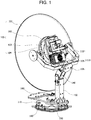
- Fig. 1 is a perspective view showing an antenna for satellite communication according to an embodiment of the present invention
- Fig. 2 is a perspective view showing an anti-vibration unit according to Fig. 1
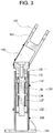
- Fig. 3 is a longitudinal cross-sectional view showing the anti-vibration unit according to Fig. 2
- Fig. 4 is a front view showing the center of the anti-vibration unit according to Fig. 3
- Fig. 5 is a perspective view showing the center of the anti-vibration unit according to Fig. 4
- Fig. 6 is a perspective view showing a mount and a mount plate for supporting the lower portion of the antenna for satellite communication according to Fig. 1
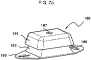
- Figs. 7a and 7b are cross-sectional views showing the mount according to Fig. 6 .
- an antenna for satellite communication 100 may include a signal transmitting and receiving unit 109 for transmitting and receiving a signal to/from the satellite; a driving unit 119 for rotating the signal transmitting and receiving unit 109 so as to enable the signal transmitting and receiving unit 109 to track the satellite; posts 140, 150 provided in a longitudinal direction for supporting the driving unit 119 ; and an anti-vibration unit 130 provided inside the posts 140, 150 for elastically supporting the signal transmitting and receiving unit 109 .
- the anti-vibration unit 130 may be a kind of vibration absorbing unit that prevents vibrations or shocks caused due to motion or movement of a moving object, such as a ship in which the antenna for satellite communication 100 is mounted, from being delivered to the signal transmitting and receiving unit 109, etc.
- the antenna for satellite communication 100 which is particularly an antenna for satellite communication s which is capable of transmitting and receiving multi polarization, is capable of two-ways communication including the Internet communication, thereby receiving signals from the satellite as well as transmitting signals toward the satellite, and is called a VSAT (Very Small Aperture Terminal) antenna.
- VSAT Very Small Aperture Terminal
- the signal transmitting and receiving unit 109 may include a reflecting plate 101 for collecting the signals to receive the signals from the satellite; a feed horn (not shown)for receiving the signals reflected from the reflecting plate 101, and a signal-processing unit 104 for processing the signals passing through the feed horn.
- the reflecting plate 101 and the signal processing unit 104 can be connected to each other through a reflecting plate flange 102 and a bearing guide 103.
- the signal transmitting and receiving unit 109 may include a reflecting plate 101, a reflecting plate flange 102, a bearing guide 103 and a signal-processing unit 104.
- the VSAT antenna is only an example for the antenna for satellite communication according to an embodiment of the present invention and the antenna described in the present invention is not limited to it having such a type or size.
- the antenna for satellite communication 100 which is mounted in a ship, etc, always tracks the satellite even in the moving ship or at turbulent waves and therefore has to be directed to the satellite. Therefore, the reflecting plate 101 should include a driving unit 119 which may rotate about the three axes, X Y, Z axes so that the reflecting plate 101 can always be directed to the desired satellite from which the signals are received.
- the driving unit 119 should be able to enable the signal transmitting and receiving unit 109 to rotate about a Z-axis direction disposed with the horn antenna, X-axis direction disposed with a horizontal post 110 or a Y axis direction disposed with a main post
- the driving unit 119 may include various kinds of motors, support frames, pulleys 105,106 and belts, etc., it is considered that the weights of the signal transmitting and receiving unit 109 and the driving unit 119 occupy most of weight of the antenna for satellite communication
- vibrations or shocks are always be delivered to the signal transmitting and receiving unit 109 by a moving ship or waves wherein, if such vibrations or shocks are not attenuated, the driving unit 119 or the signal transmitting and receiving unit 109 can be damaged or the signal transmission and reception sensitivity can be lowered due to increased fatigue load, etc.
- an anti-vibration unit 130 is arranged inside the posts 140 150 in orders to attenuate the vibrations or shocks on the signal transmitting and receiving unit 109 or the driving unit 119.
- the posts 140 150 are a pillar for supporting most of the weight of the antenna for satellite communication 100 including the signal transmitting and receiving unit 109 and the driving unit 119 and for securing the antenna for satellite communication 100 to a ship or the like, and it is necessary that the inside of the posts should be in a form of hollow to secure a sufficient space therein.
- Various kinds of cables, which supply power or transmit the signals to various kinds electric/electronic components composing the signal transmitting and receiving unit 109 and the driving unit 119, may pass through the inside of the posts 140, 150 or the anti-vibration unit 130 can be arranged inside the posts 140, 150.
- the posts 140, 150 may be separately formed by the first post 140 and the second post 150. That is, it is possible to separately form the first post 140 on which the signal transmitting and receiving unit 109 or the driving unit 119 is mounted and the second post 150 provided at the lower portion of the first post 140 to be spaced apart from the first post 140.
- a horizontal post 110 of the driving unit 119 is rotatably mounted on the first post 140 at the upper portion, and a pedestal 160 is fixed to the lower end of the second post 150.
- the pedestal 160 may be rotated on a damping base 170.
- the bottom of the damping base 170 is elastically supported by a plurality of mounts 180, and the mount 180 may be fixed on the mount plate 190.
- the lower end of the second post 150 may be supported by the plurality of mounts 180 disposed radically with respect to the center of the second post 150.
- the mount 180 is capable of attenuating twists as well as vertical or horizontal directional vibrations applied to the components disposed above the top of the damping base 170.
- the anti-vibration unit 130 is accommodated inside the second post 150, and the top of the anti-vibration unit 130 can be connected with the first post 140. That is, the anti-vibration unit 130 is arranged inside the second post 150 so as to prevent vibrations or shocks, which are caused due to the motion or movement of a moving object on which the antenna 100 is mounted, from being applied to the signal transmitting and receiving unit 109 or the driving unit 119, etc. when the first post 140 performs a vertical motion or lifts up with respect to the second post 150.
- the first post 140 may have a sloped shape with respect to the second post 150, to easily adjust an elevation angle of the reflecting plate 101.
- the form, position, connection angle and the like of the first post 140 and the second post 150 may be properly adjusted depending on the performance, the size and the like of the antenna.
- the first post 140 is formed with a connecting hole 142 at the top for rotatably connecting the horizontal post 110, and an end portion 141 in which the connecting hole 142 is provided can be formed in such a shape that the width is gradually narrower toward the top.
- the second post 150 is a hollow tube in a vertically upstanding form. At this time, it is desirable that the cross surface of the second post 150 has a non-circular shape for preventing rotation at a state in which the first post 140 is connected to the second post 150. A flange 151 formed at the bottom of the second post 150 is fixed to the pedestal 160.
- the anti-vibration unit 130 may be inserted into second post 150.
- the top and bottom of the anti-vibration unit 130 can be fixed and supported by an upper holder neck 131 and a lower holder neck 132, respectively.
- the upper holder neck 131 and lower holder neck 132 are inserted into the second post 150, and thereby the anti-vibration unit 130 may be provided inside the second post 150.
- the upper holder neck 131 and lower holder neck 132 may individually be fixed to the second post 150 by a fastening member (not shown) such as a bolt.
- the anti-vibration unit 130 may include a damper shaft 133, which is provided inside the second post 150 along the longitudinal direction of the second post 150, and a plurality of damper springs 136,137 provided on the outer surface of the damper shaft 133 along the longitudinal direction thereof
- the damper shaft 133 may be formed with a compartment 134 for separating namely, spatially separating the damper springs 136 137.
- the compartment 134 protrudes beyond the outer circumferential surface of the damper shaft 133 and is capable of supporting the damper springs 136,137 arranged at the upper and lower portions of the compartment 134, respectively.
- the anti-vibration unit 130 may include an upper holder neck 131 for supporting the upper portion of the damper shaft 133 and a lower holder neck 132 for supporting the lower portion of the damper shaft 133.
- the top and lower of the damper shaft 133 may be formed to upwardly and downwardly move through the upper holder neck 131 and the lower holder neck 132, respectively.
- the top and lower of the damper shaft 133 are formed in such a manner as to penetrate through the upper holder neck 131 and the lower holder neck 132.
- the damper shaft 133 is elastically supported by the damper spring 136 which is located between the upper holder neck 131 and the compartment 134 and the damper spring 137 which is located between the compartment 134 and the lower holder neck 132, the top and lower of the damper shaft 133 can penetrate through the upper holder neck 131 and the lower holder neck 132.
- the upper neck holder 131, the lower neck holder 132 and the compartment 134, which are components directly in contact with the damper springs 136,137, are directly bearing on the weight or external force to be applied to the damper springs 136 137.
- the top of the damper shaft 133 passes through the upper holder neck 131 and is connected to the first post 140.
- the top of damper shaft 133 may directly be connected to the first post 140, or the first post 140 may be connected to the anti-vibration unit 130 or the damper shaft 133 by a base holder 135.
- the base holder 135 is a cap-shaped member to be placed at the top of the damper shaft 133 and inserted into the top of the second post 150 in such a manner as to move up and down.
- the first post 140 may be connected and fixed to the upper portion of the base holder 135.
- the plurality of damper springs 136,137 is provided along the longitudinal direction of the damper shaft 133 on the outer surface thereof. It is preferable to vertically arrange the damper springs in such a manner as to be separated to be each other.
- the damper shaft 133 may be formed with a compartment 134 at the center to spatially separate the damper spring 136, 137.
- an anti-vibration unit 130 having two damper springs 136,137 is shown.
- the number of the damper springs may be determined according to the size of the vibrations or shocks to be attenuated.
- the first damper spring 136 and the second damper spring 137 may be formed to have the same shape and the same elasticity coefficient, but they may also be differently formed from each other in at least one of winding length, cross-sectional shape, size of diameter and elastic modulus.
- the winding length is a length when the wound damper spring is unfolded to be in a linear type
- the cross-sectional shape is a cross-sectional shape of the wire that is unfolded to be in a linear type.
- the first damper spring 136 located at the upper portion uses a soft spring having a small elasticity coefficient and the second damper spring 137 located at the lower portion uses a hard spring having a larger elasticity coefficient, thereby attenuating vibrations which occur in a ship due to waves or the like by means of the whole damper springs 136, 137 in a state in which forces caused by the self-weights of the signal transmitting and receiving unit 109 and the driving unit 119 are supported by the first soft damper spring 136 at the upper portion.
- the first damper spring 136 uses a long spring having a smaller elasticity coefficient than the second damper spring 137.
- the anti-vibration unit 130 of the antenna for satellite communication 100 may further include an elastic member 138 which is provided between windings of the damper springs 136, 137.
- the elastic member 138 has the same winding form as the damper springs 136,137 and may be capable of preventing a contact between the windings of the damper springs 136,137. If no elastic member 138 is present, when an excessive weight is loaded on the damper springs 136 137, the damper springs 136 137 are completely compressed and the weight may continually be applied in a state in which the windings of the damper springs are in contact with each other.
- the damper springs may not be able to absorb the vibrations or shocks and may cause a damage of the antenna, etc.
- the elastic member 138 may be formed using at least one of rubber, silicone and urethane. When the urethane is used, it is preferable to use a low-resistance urethane or low-elasticity urethane.
- the mount 180 may include a cap 181 for supporting the mount 180 under the bottom of the damping base 170, a buffer 183 formed at the lower portion of the cap 181, and a mount plate 185 formed under the bottom of the buffer 183.
- the cap 181 may be formed of a metallic material and the buffer 183 may be formed of a rubber or silicone material.
- the buffer 183 and the cap 181 may be coupled to each other by using a fastening member such as a bolt or an adhesive, and the cap 181 may be formed with a through - hole 187 for coupling them.
- the mount plate 185 may be formed with a fastening hole 186 for fastening the mount 180 to the mount plate 190.
- the buffer 183 makes it possible to attenuate the vibrations or shocks in the up and down direction, in the left and right direction, or in the front and rear direction on the cap 181.
- a plurality of mounts 180 may be radically provided at a certain distance around the center of the second post 150.
- the plurality of mounts 180 may be provided at the equal intervals from the center of the second post 150.
- the anti-vibration unit 130 mainly attenuates the vibrations or shocks applied to the signal transmitting and receiving unit 109 in the up and down direction, namely the Y-axis, while the mount 180 is capable of attenuating the vibrations or shocks applied to the signal transmitting and receiving unit 109 in the up and down direction, in the left and right direction, or in the front and rear direction. That is, the mount 180 may prevent the vibrations or the shocks caused in the X-axis direction, in the Y-axis direction and in the Z-axis direction from being transmitted to the signal transmitting and receiving unit 109 or the driving unit 119. In addition, the mount 180 may also attenuate a torsion motion or the like generated around the Y-axis or the center of the second post 150.
- the vertically arranged anti-vibration unit 130 has a large absorption capacity for the vibrations or shocks in the Y-axis direction, while the mount 180 has a smaller absorption capacity for the vibrations or shocks than the anti-vibration unit 130.
- the anti-vibration unit 130 and the mount 180 may attenuate external forces or vibrations having vibration frequencies with different bands, the anti-vibration unit 130 and the mount 180 may complementarily attenuate or absorb the vibrations or shocks.
- the damper springs 136,137 of the anti-vibration unit 130 are capable of attenuating vibrations with the low frequency band
- the mount 180 is capable of attenuating vibrations with the relatively high frequency band.
- the elastic member 138 in the anti-vibration unit 130 may prevent the satellite antenna from being broken and damaged resulting from a high intensity of impact.
- the antenna for satellite communication 100 is capable of absorbing or attenuating most of the vibrations, the external forces or the shocks which are applied to the antenna for satellite communication by using the anti-vibration unit 130 having the damper spring 136 137 and the elastic member 138 and the mount 180, thereby increasing the durability, performance or the like of the antenna for satellite communication.
- the first post 140 may perform a vertical motion relative to the second post 150 by means of the anti-vibration unit 130.
- the first post 140 since the first post 140 is not completely upright like the second post 150 but tilted, a point at which the weights of the reflecting plate 101 and the other components connected to the first post 140 are applied, is surely spaced from the center of the second post 150.
- the base holder 135 does not move along an absolutely perpendicular path because of the loads applied to the top of the first post 140.
- the antenna for satellite communication 100 may include a lifting guide 120, by the lifting guide, the base holder 135 can move upwardly and downwardly in the absolutely perpendicular direction and the first post 140 can move upwardly and downwardly in the same state with respect to the second post 150.
- a lifting guide 120 may be formed on the same one side of the first post 140 and the second post 150 to guide the up-down motion of the first post 140 with respect to the second post 150.
- the lifting guide 120 may ensure that the first post 140 or the base holder 135 upwardly and downwardly moves or elevates along the vertical path with respect to the second post 150 and prevent the first post 140 from tilting or rotating when it elevates or upwardly and downwardly moves.
- the lifting guide 120 may include a pair of guide bearings 126 arranged at any one side of the first post 140 and the second post 150; and lifting members 121,122,123 mounted at the side of the other post, located between the pair of guide bearings 126, and being in contact with at least one of the guide bearings 126.
- the lifting members 121,122,123 may include a first stopper 121 mounted on any one side of the first post 140 and the second post 150; a guide 123 formed integrally with the first stopper 121 in such a manner as to have a smaller width than the first stopper 121 and located between the pair of guide bearings 126; and a second stopper 122 formed integrally with the guide 123 in such a manner as to have a width greater than the first stopper 121 and opposite to the first stopper 121 with respect to the guide 123.
- the first stopper 121 of the lifting members is fixed to one side surface of the first post 140 by a fastening member(not shown) such as a bolt, and the pair of guide bearings 126 may be fixedly mounted on the same side surface of the second post 150.
- the pair of guide bearings 126 has a shape of a wheel bearing, and rotates in contact with the guide 123, which passes there between.
- the guide bearing 126 is preferably formed of an elastic material for cushioning the shocks when it is in contact with the first stopper 121 or the second stopper 122.
- the guide 123 of the lifting members has a small width than the first stopper 121, and may be formed to have substantially the same width as the distance between the guide bearings 126.
- the guide 123 performs a lift/up-down movement between the guide bearings 126 and comes into contact with at least one of guide bearings 126 at the time of the lift/up-down movement.
- the up-down movement of the first post 140 may be prevented from getting out of the vertical path because the guide 123 performs the lift/up-down movement in contact with the guide bearings 126.
- the second stopper 122 is located at one side of the second post 150 together with guide bearings 126. As such, any one of the first stopper 121 and second stopper 122 may be located at one side of the same post 140, 150 as the pair of guide bearings 126.
- the length of the guide 123 may be formed smaller than the maximum relative movement distance of the first post 140 with respect to the second post 150. If the length of the guide 123 is equal to or longer than the maximum relative movement distance of the first post 140 with respect to the second post 150, it is preferable that the length of the guide 123 is formed smaller than the maximum relative movement distance of the first post 140 with respect to the second post 150, because the mutual interference may occur between the first post 140 and the second post 150.
- the first post 140 may upwardly and downwardly move or lift up over the length of the guide, namely the shortest distance between the first stopper 121 and the second stopper 122. That is to say, the first post 140 may upwardly and downwardly move or lift up until the end of the first stopper 121 and the end of the second stopper 122 adjacent to the guide bearings 126 are in contact with the guide bearings 126.
- a curved surface may be formed a side surface at an area where the first stopper 121 and the second stopper 122 are in contact with the guide 123. That is to say, the corner sides of the end of the first stopper 121 and the end of the second stopper 122 adjacent to the guide bearings 126 are formed to be a curved surface, thereby increasing an area that is in contact with the guide bearings 126 and preventing the guide bearings 126 from being damaged or worn down by the first stopper 121 and the second stopper 122.
- the invention may be used for an antenna for satellite or the like mounted in a moving object including a vehicle, a ship, etc.
Landscapes
- Engineering & Computer Science (AREA)
- General Engineering & Computer Science (AREA)
- Remote Sensing (AREA)
- Mechanical Engineering (AREA)
- Physics & Mathematics (AREA)
- Acoustics & Sound (AREA)
- Aviation & Aerospace Engineering (AREA)
- Details Of Aerials (AREA)
- Support Of Aerials (AREA)
Description
- The present invention relates to an antenna for satellite communication, and more particular to an antenna for satellite communication in which an anti-vibration unit is formed inside posts that support a signal transmitting and receiving unit, wherein the anti-vibration unit prevents vibrations caused by movement of an antenna for satellite communication -mounted object from being applied to the signal transmitting and receiving unit.
- A satellite antenna is commonly used for satellite communication, high-capacity wireless communication, etc The satellite antenna concentrates signals received using the principle of a reflecting telescope on at least one focus. In general, on the focal position of the satellite antenna, a horn antenna or a feed horn may be installed Here, the representative satellite antenna may be a parabolic antenna.
- The satellite antenna generally has a pedestal structure capable of performing rotation movement based on 3 axes because the horn antenna or the feed horn should always be positioned toward the satellite located at constant position. A power transmission unit using a plurality of belts and pulleys is used for the satellite antenna so as to enable the 3 axes-based rotation movements.
- The satellite antenna is used with a damper having a parabolic shape to support the weight of a main reflecting plate, including the power transmission unit of the satellite antenna, or to prevent vibrations or shocks caused due to the surrounding environment.
In the conventional satellite antenna, a single spring disposed inside a pillar member is used to attenuate the vibrations or shocks on the antenna, but vibration or shock absorbing capacity is not large because a single spring is used, thereby causing a problem that sufficient attenuation is not performed. -
US 5,985,169 A discloses such kind of satellite antenna with a anti-vibration unit provided inside a post for elastically supporting the transmitting and receiving unit and the driving unit. - Further, satellite antennas are disclosed in
US 2010/149,059 A1 andUS 2012/001,816 A1 . - Further, when the spring is compressed to the maximum and the windings of the spring are directly in contact with each other, the shocks and vibrations will not be absorbed at all, and the non-absorbed shocks and vibrations are transmitted to the electronic components of the satellite antenna or the like, hereby causing a problem that the antenna is malfunctioning.
- The present invention provides an antenna for satellite communication having an anti-vibration unit spatially formed in one body with posts for supporting a signal transmitting and receiving unit including a main reflecting plate.
- The anti-vibration unit is capable of extending the range of the shock absorption by using a plurality of damper springs.
- Further the anti-vibration unit is capable of preventing a direct contact between the windings of the damper spring.
- Further the anti-vibration unit is capable of attenuating a vibration or shock applied in up-down direction as well as other direction.
- In order to accomplish the objects as described above, the antenna for satellite communication according to an embodiment of the present invention may comprise a signal transmitting and receiving unit for receiving or transmitting a signal from/to the satellite; a driving unit for rotating the signal transmitting and receiving unit so as to enable the signal transmitting and receiving unit to track the satellite; an anti-vibration unit provided inside the posts for elastically supporting the signal transmitting and receiving unit or the driving unit.
- By providing the anti-vibration unit inside the posts as described above, it is possible to increase availability for a circumferential space of the posts and to simplify the structure of the anti-vibration unit.
- The posts include a first post on which the signal transmitting and receiving unit or the driving unit is mounted and a second post provided at a lower portion of the first post in such a manner as to be spaced apart from each other. The anti-vibration unit may be accommodated inside the second post and the first post may be connected to the top the anti-vibration unit.
- The anti-vibration unit may include a damper shaft provided inside the second post along the longitudinal direction of the second post and a plurality of damper springs provided on the outer surface of the damper shaft along the longitudinal direction of the damper shaft.
- The anti-vibration unit includes an upper holder neck for supporting the upper portion of the damper shaft and a lower holder neck for supporting the lower portion of the damper, and the top and lower of the damper shaft may be formed to upwardly and downwardly move through the upper holder neck and the lower holder neck, respectively.
- The plurality of damper springs is vertically arranged along the longitudinal direction of the damper shaft, and the damper shaft may be formed with a compartment for separating the damper spring.
- The plurality of damper springs may have at least different one of winding length, cross-sectional shape, diameter and elastic modulus from each other.
- The damper may further include an elastic member provided between the windings of the damper spring.
- The elastic member has the same winding form as the damper spring and may prevent the windings of the damper spring from being in contact with each other.
- The elastic member may be formed using at least one of rubber, silicone and urethane.
- A lifting guide for vertical movement of the first post with respect to the second post may be formed on the same side of the first post and the second post.
- The lifting guide may include a pair of guide bearings mounted at any one side of the first post and the second post; and lifting members mount at the side of the other post, located between the pair of guide bearings, and being in contact at least one of the guide bearings.
- The lifting members may include a first stopper mounted at one side of either the first post or the second post; a guide formed integrally with the first stopper in such a manner as to have a smaller width than the first stopper and located between the pair of guide bearings; and a second stopper formed integrally with the guide in such a manner as to have a greater width than the first stopper and opposite to the first stopper with respect to the guide.
- Any one of the first stopper and the second stopper may be located at one same side of the posts as the pair of guide bearings.
- A length of the guide is formed to be smaller than the maximum relative movement distance of the first post with respect to the second post. A curved surface may be formed on a side surface at an area where the first stopper and the second stopper are connected with the guide.
- The lower end of the second post is supported by a plurality of mounts disposed radically with respect to the center of the second post, and the anti-vibration unit and the mount are capable of attenuating vibrations or external forces with vibration frequencies of the different bands.
- As described above, the antenna for satellite communication of the present invention is capable of improving availability for circumferential space of the posts by forming an anti-vibration unit within the posts.
- The antenna for satellite communication of the present invention is capable of preventing a direct contact between the windings of the damper spring by inserting the elastic member between the windings of the damper spring.
- The antenna for satellite communication of the present invention is capable of attenuating the vibrations or shocks applied to the signal transmitting and receiving unit in different directions as well as in a longitudinal direction.
- The antenna for satellite communication of the present invention is capable of preventing the posts, which perform an uplift or vertical movement due to an elastic force of the anti-vibration unit from being separated from each other, or rotating by including a lift guide.
- The antenna for satellite communication of the present invention is capable of increasing the vibration or shock absorbing capacity with respect to the vertical direction by including a plurality of damper springs which form an anti-vibration unit and setting the springs differently in physical constant.
-
-
Fig. 1 is a perspective view showing an antenna for satellite communication according to an embodiment of the present invention. -
Fig. 2 is a perspective view showing an anti-vibration unit according toFig. 1 . -
Fig. 3 is a longitudinal cross-sectional view showing the anti-vibration unit according toFig. 2 . -
Fig. 4 is a front view showing the center of the anti-vibration unit according toFig. 3 . -
Fig. 5 is a perspective view showing the center of the anti-vibration unit according toFig. 4 . -
Fig. 6 is a perspective view showing a mount and a mount plate for supporting the lower portion of the antenna for satellite communication according toFig. 1 . -
Fig. 7a andFig. 7b are cross-sectional views showing the mount according toFig. 6 . - Hereinafter, an embodiment of the present invention will be described in detail with reference to the accompanying drawings. However, the present invention is not limited to or restricted by the embodiment. The present invention is defined by the scope of the appended claims.
- Like reference numerals in the drawings denote like elements.
-
Fig. 1 is a perspective view showing an antenna for satellite communication according to an embodiment of the present invention,Fig. 2 is a perspective view showing an anti-vibration unit according toFig. 1 ,Fig. 3 is a longitudinal cross-sectional view showing the anti-vibration unit according toFig. 2 ,Fig. 4 is a front view showing the center of the anti-vibration unit according toFig. 3 ,Fig. 5 is a perspective view showing the center of the anti-vibration unit according toFig. 4 ,Fig. 6 is a perspective view showing a mount and a mount plate for supporting the lower portion of the antenna for satellite communication according toFig. 1 , andFigs. 7a and 7b are cross-sectional views showing the mount according toFig. 6 . - Referring to
Fig. 1 , an antenna for satellite communication 100 according to an embodiment of the present invention may include a signal transmitting and receivingunit 109 for transmitting and receiving a signal to/from the satellite; adriving unit 119 for rotating the signal transmitting and receivingunit 109 so as to enable the signal transmitting and receivingunit 109 to track the satellite;posts driving unit 119 ; and ananti-vibration unit 130 provided inside theposts unit 109 . By providing theanti-vibration unit 130 inside theposts - Here, the
anti-vibration unit 130 may be a kind of vibration absorbing unit that prevents vibrations or shocks caused due to motion or movement of a moving object, such as a ship in which the antenna for satellite communication 100 is mounted, from being delivered to the signal transmitting and receivingunit 109, etc. - The antenna for satellite communication 100 according to an embodiment of the present invention, which is particularly an antenna for satellite communication s which is capable of transmitting and receiving multi polarization, is capable of two-ways communication including the Internet communication, thereby receiving signals from the satellite as well as transmitting signals toward the satellite, and is called a VSAT (Very Small Aperture Terminal) antenna.
- Here, the signal transmitting and receiving
unit 109 may include areflecting plate 101 for collecting the signals to receive the signals from the satellite; a feed horn (not shown)for receiving the signals reflected from the reflectingplate 101, and a signal-processing unit 104 for processing the signals passing through the feed horn. The reflectingplate 101 and thesignal processing unit 104 can be connected to each other through a reflectingplate flange 102 and abearing guide 103. Thus, the signal transmitting and receivingunit 109 may include a reflectingplate 101, a reflectingplate flange 102, abearing guide 103 and a signal-processing unit 104. - However, the VSAT antenna is only an example for the antenna for satellite communication according to an embodiment of the present invention and the antenna described in the present invention is not limited to it having such a type or size.
- On the other hand, the antenna for satellite communication 100 according to an embodiment of the present invention, which is mounted in a ship, etc, always tracks the satellite even in the moving ship or at turbulent waves and therefore has to be directed to the satellite. Therefore, the reflecting
plate 101 should include adriving unit 119 which may rotate about the three axes, X Y, Z axes so that the reflectingplate 101 can always be directed to the desired satellite from which the signals are received. - As shown in
Fig. 1 , the drivingunit 119 should be able to enable the signal transmitting and receivingunit 109 to rotate about a Z-axis direction disposed with the horn antenna, X-axis direction disposed with ahorizontal post 110 or a Y axis direction disposed with a main post Since thedriving unit 119 may include various kinds of motors, support frames, pulleys 105,106 and belts, etc., it is considered that the weights of the signal transmitting and receivingunit 109 and thedriving unit 119 occupy most of weight of the antenna for satellite communication Thus, vibrations or shocks are always be delivered to the signal transmitting and receivingunit 109 by a moving ship or waves wherein, if such vibrations or shocks are not attenuated, the drivingunit 119 or the signal transmitting and receivingunit 109 can be damaged or the signal transmission and reception sensitivity can be lowered due to increased fatigue load, etc. - Likewise, an
anti-vibration unit 130 is arranged inside theposts 140 150 in orders to attenuate the vibrations or shocks on the signal transmitting and receivingunit 109 or thedriving unit 119. - The
posts 140 150 are a pillar for supporting most of the weight of the antenna for satellite communication 100 including the signal transmitting and receivingunit 109 and thedriving unit 119 and for securing the antenna for satellite communication 100 to a ship or the like, and it is necessary that the inside of the posts should be in a form of hollow to secure a sufficient space therein. Various kinds of cables, which supply power or transmit the signals to various kinds electric/electronic components composing the signal transmitting and receivingunit 109 and thedriving unit 119, may pass through the inside of theposts anti-vibration unit 130 can be arranged inside theposts - The
posts first post 140 and thesecond post 150. That is, it is possible to separately form thefirst post 140 on which the signal transmitting and receivingunit 109 or thedriving unit 119 is mounted and thesecond post 150 provided at the lower portion of thefirst post 140 to be spaced apart from thefirst post 140. - A
horizontal post 110 of thedriving unit 119 is rotatably mounted on thefirst post 140 at the upper portion, and apedestal 160 is fixed to the lower end of thesecond post 150. Thepedestal 160 may be rotated on a dampingbase 170. - The bottom of the damping
base 170 is elastically supported by a plurality ofmounts 180, and themount 180 may be fixed on themount plate 190. Thus, the lower end of thesecond post 150 may be supported by the plurality ofmounts 180 disposed radically with respect to the center of thesecond post 150. Themount 180 is capable of attenuating twists as well as vertical or horizontal directional vibrations applied to the components disposed above the top of the dampingbase 170. - Referring to
Fig. 2 , theanti-vibration unit 130 is accommodated inside thesecond post 150, and the top of theanti-vibration unit 130 can be connected with thefirst post 140. That is, theanti-vibration unit 130 is arranged inside thesecond post 150 so as to prevent vibrations or shocks, which are caused due to the motion or movement of a moving object on which the antenna 100 is mounted, from being applied to the signal transmitting and receivingunit 109 or thedriving unit 119, etc. when thefirst post 140 performs a vertical motion or lifts up with respect to thesecond post 150. - The
first post 140 may have a sloped shape with respect to thesecond post 150, to easily adjust an elevation angle of the reflectingplate 101. However, the form, position, connection angle and the like of thefirst post 140 and thesecond post 150 may be properly adjusted depending on the performance, the size and the like of the antenna. - The
first post 140 is formed with a connectinghole 142 at the top for rotatably connecting thehorizontal post 110, and anend portion 141 in which the connectinghole 142 is provided can be formed in such a shape that the width is gradually narrower toward the top. A lower pillar (not shown) of thefirst post 140, which is connected to a lower portion of theend portion 141, has a trapezoidal shape when viewed from the side. - The
second post 150 is a hollow tube in a vertically upstanding form. At this time, it is desirable that the cross surface of thesecond post 150 has a non-circular shape for preventing rotation at a state in which thefirst post 140 is connected to thesecond post 150. Aflange 151 formed at the bottom of thesecond post 150 is fixed to thepedestal 160. - As shown in
Figs. 2 and3 , theanti-vibration unit 130 may be inserted intosecond post 150. The top and bottom of theanti-vibration unit 130 can be fixed and supported by anupper holder neck 131 and alower holder neck 132, respectively. Theupper holder neck 131 andlower holder neck 132 are inserted into thesecond post 150, and thereby theanti-vibration unit 130 may be provided inside thesecond post 150. Theupper holder neck 131 andlower holder neck 132 may individually be fixed to thesecond post 150 by a fastening member (not shown) such as a bolt. - Meanwhile, the
anti-vibration unit 130 may include adamper shaft 133, which is provided inside thesecond post 150 along the longitudinal direction of thesecond post 150, and a plurality of damper springs 136,137 provided on the outer surface of thedamper shaft 133 along the longitudinal direction thereof Thedamper shaft 133 may be formed with acompartment 134 for separating namely, spatially separating the damper springs 136 137. Thecompartment 134 protrudes beyond the outer circumferential surface of thedamper shaft 133 and is capable of supporting the damper springs 136,137 arranged at the upper and lower portions of thecompartment 134, respectively. - Referring to
Fig. 3 , theanti-vibration unit 130 may include anupper holder neck 131 for supporting the upper portion of thedamper shaft 133 and alower holder neck 132 for supporting the lower portion of thedamper shaft 133. The top and lower of thedamper shaft 133 may be formed to upwardly and downwardly move through theupper holder neck 131 and thelower holder neck 132, respectively. The top and lower of thedamper shaft 133 are formed in such a manner as to penetrate through theupper holder neck 131 and thelower holder neck 132. Since thedamper shaft 133 is elastically supported by thedamper spring 136 which is located between theupper holder neck 131 and thecompartment 134 and thedamper spring 137 which is located between thecompartment 134 and thelower holder neck 132, the top and lower of thedamper shaft 133 can penetrate through theupper holder neck 131 and thelower holder neck 132. - The
upper neck holder 131, thelower neck holder 132 and thecompartment 134, which are components directly in contact with the damper springs 136,137, are directly bearing on the weight or external force to be applied to the damper springs 136 137. - The top of the
damper shaft 133 passes through theupper holder neck 131 and is connected to thefirst post 140. The top ofdamper shaft 133 may directly be connected to thefirst post 140, or thefirst post 140 may be connected to theanti-vibration unit 130 or thedamper shaft 133 by abase holder 135. - The
base holder 135 is a cap-shaped member to be placed at the top of thedamper shaft 133 and inserted into the top of thesecond post 150 in such a manner as to move up and down. Thefirst post 140 may be connected and fixed to the upper portion of thebase holder 135. - Meanwhile, the plurality of damper springs 136,137 is provided along the longitudinal direction of the
damper shaft 133 on the outer surface thereof. It is preferable to vertically arrange the damper springs in such a manner as to be separated to be each other. To this, thedamper shaft 133 may be formed with acompartment 134 at the center to spatially separate thedamper spring - In
Figs 3 to 5 , ananti-vibration unit 130 having two damper springs 136,137 is shown. However, the number of the damper springs may be determined according to the size of the vibrations or shocks to be attenuated. - The
first damper spring 136 and thesecond damper spring 137 may be formed to have the same shape and the same elasticity coefficient, but they may also be differently formed from each other in at least one of winding length, cross-sectional shape, size of diameter and elastic modulus. Here, the winding length is a length when the wound damper spring is unfolded to be in a linear type and the cross-sectional shape is a cross-sectional shape of the wire that is unfolded to be in a linear type. - For example, the
first damper spring 136 located at the upper portion uses a soft spring having a small elasticity coefficient and thesecond damper spring 137 located at the lower portion uses a hard spring having a larger elasticity coefficient, thereby attenuating vibrations which occur in a ship due to waves or the like by means of the whole damper springs 136, 137 in a state in which forces caused by the self-weights of the signal transmitting and receivingunit 109 and thedriving unit 119 are supported by the firstsoft damper spring 136 at the upper portion. Further, in consideration of initial compression of the damper springs by the self-weights of the signal transmitting and receivingunit 109 and thedriving unit 119, it is preferable that thefirst damper spring 136 uses a long spring having a smaller elasticity coefficient than thesecond damper spring 137. - Here, the
anti-vibration unit 130 of the antenna for satellite communication 100 according to an embodiment of the present invention may further include anelastic member 138 which is provided between windings of the damper springs 136, 137. As shown inFigs. 4 and5 , theelastic member 138 has the same winding form as the damper springs 136,137 and may be capable of preventing a contact between the windings of the damper springs 136,137. If noelastic member 138 is present, when an excessive weight is loaded on the damper springs 136 137, the damper springs 136 137 are completely compressed and the weight may continually be applied in a state in which the windings of the damper springs are in contact with each other. As a result, the damper springs may not be able to absorb the vibrations or shocks and may cause a damage of the antenna, etc. In order to prevent this phenomenon, it is preferable to separately insert theelastic member 138 between the windings of the damper springs 136, 137. - The
elastic member 138 may be formed using at least one of rubber, silicone and urethane. When the urethane is used, it is preferable to use a low-resistance urethane or low-elasticity urethane. - On the other hand, in
Figs. 6 ,7a and 7b , amount 180 is shown, themount 180 may include acap 181 for supporting themount 180 under the bottom of the dampingbase 170, abuffer 183 formed at the lower portion of thecap 181, and amount plate 185 formed under the bottom of thebuffer 183. - The
cap 181 may be formed of a metallic material and thebuffer 183 may be formed of a rubber or silicone material. Thebuffer 183 and thecap 181 may be coupled to each other by using a fastening member such as a bolt or an adhesive, and thecap 181 may be formed with a through -hole 187 for coupling them. Themount plate 185 may be formed with afastening hole 186 for fastening themount 180 to themount plate 190. Thebuffer 183 makes it possible to attenuate the vibrations or shocks in the up and down direction, in the left and right direction, or in the front and rear direction on thecap 181. - A plurality of
mounts 180 may be radically provided at a certain distance around the center of thesecond post 150. For example, the plurality ofmounts 180 may be provided at the equal intervals from the center of thesecond post 150. - The
anti-vibration unit 130 mainly attenuates the vibrations or shocks applied to the signal transmitting and receivingunit 109 in the up and down direction, namely the Y-axis, while themount 180 is capable of attenuating the vibrations or shocks applied to the signal transmitting and receivingunit 109 in the up and down direction, in the left and right direction, or in the front and rear direction. That is, themount 180 may prevent the vibrations or the shocks caused in the X-axis direction, in the Y-axis direction and in the Z-axis direction from being transmitted to the signal transmitting and receivingunit 109 or thedriving unit 119. In addition, themount 180 may also attenuate a torsion motion or the like generated around the Y-axis or the center of thesecond post 150. - The vertically arranged
anti-vibration unit 130 has a large absorption capacity for the vibrations or shocks in the Y-axis direction, while themount 180 has a smaller absorption capacity for the vibrations or shocks than theanti-vibration unit 130. - The
anti-vibration unit 130 and themount 180 may attenuate external forces or vibrations having vibration frequencies with different bands, theanti-vibration unit 130 and themount 180 may complementarily attenuate or absorb the vibrations or shocks. For example, the damper springs 136,137 of theanti-vibration unit 130 are capable of attenuating vibrations with the low frequency band, and themount 180 is capable of attenuating vibrations with the relatively high frequency band. In addition, theelastic member 138 in theanti-vibration unit 130 may prevent the satellite antenna from being broken and damaged resulting from a high intensity of impact. Thus, the antenna for satellite communication 100 according to an embodiment of the present invention is capable of absorbing or attenuating most of the vibrations, the external forces or the shocks which are applied to the antenna for satellite communication by using theanti-vibration unit 130 having thedamper spring 136 137 and theelastic member 138 and themount 180, thereby increasing the durability, performance or the like of the antenna for satellite communication. - Referring to
Fig. 2 , thefirst post 140 may perform a vertical motion relative to thesecond post 150 by means of theanti-vibration unit 130. However, since thefirst post 140 is not completely upright like thesecond post 150 but tilted, a point at which the weights of the reflectingplate 101 and the other components connected to thefirst post 140 are applied, is surely spaced from the center of thesecond post 150. Thus, there is a possibility that thebase holder 135 does not move along an absolutely perpendicular path because of the loads applied to the top of thefirst post 140. The antenna for satellite communication 100 according to the present invention may include a liftingguide 120, by the lifting guide, thebase holder 135 can move upwardly and downwardly in the absolutely perpendicular direction and thefirst post 140 can move upwardly and downwardly in the same state with respect to thesecond post 150. - As shown in
Fig.2 , a liftingguide 120 may be formed on the same one side of thefirst post 140 and thesecond post 150 to guide the up-down motion of thefirst post 140 with respect to thesecond post 150. - The lifting
guide 120 may ensure that thefirst post 140 or thebase holder 135 upwardly and downwardly moves or elevates along the vertical path with respect to thesecond post 150 and prevent thefirst post 140 from tilting or rotating when it elevates or upwardly and downwardly moves. The liftingguide 120 may include a pair ofguide bearings 126 arranged at any one side of thefirst post 140 and thesecond post 150; and lifting members 121,122,123 mounted at the side of the other post, located between the pair ofguide bearings 126, and being in contact with at least one of theguide bearings 126. - The lifting members 121,122,123 may include a
first stopper 121 mounted on any one side of thefirst post 140 and thesecond post 150; aguide 123 formed integrally with thefirst stopper 121 in such a manner as to have a smaller width than thefirst stopper 121 and located between the pair ofguide bearings 126; and asecond stopper 122 formed integrally with theguide 123 in such a manner as to have a width greater than thefirst stopper 121 and opposite to thefirst stopper 121 with respect to theguide 123. - Referring to
Fig. 2 , thefirst stopper 121 of the lifting members is fixed to one side surface of thefirst post 140 by a fastening member(not shown) such as a bolt, and the pair ofguide bearings 126 may be fixedly mounted on the same side surface of thesecond post 150. The pair ofguide bearings 126 has a shape of a wheel bearing, and rotates in contact with theguide 123, which passes there between. Theguide bearing 126 is preferably formed of an elastic material for cushioning the shocks when it is in contact with thefirst stopper 121 or thesecond stopper 122. - The
guide 123 of the lifting members has a small width than thefirst stopper 121, and may be formed to have substantially the same width as the distance between theguide bearings 126. Theguide 123 performs a lift/up-down movement between theguide bearings 126 and comes into contact with at least one ofguide bearings 126 at the time of the lift/up-down movement. The up-down movement of thefirst post 140 may be prevented from getting out of the vertical path because theguide 123 performs the lift/up-down movement in contact with theguide bearings 126. - The
second stopper 122 is located at one side of thesecond post 150 together withguide bearings 126. As such, any one of thefirst stopper 121 andsecond stopper 122 may be located at one side of thesame post guide bearings 126. - The length of the
guide 123 may be formed smaller than the maximum relative movement distance of thefirst post 140 with respect to thesecond post 150. If the length of theguide 123 is equal to or longer than the maximum relative movement distance of thefirst post 140 with respect to thesecond post 150, it is preferable that the length of theguide 123 is formed smaller than the maximum relative movement distance of thefirst post 140 with respect to thesecond post 150, because the mutual interference may occur between thefirst post 140 and thesecond post 150. - The
first post 140 may upwardly and downwardly move or lift up over the length of the guide, namely the shortest distance between thefirst stopper 121 and thesecond stopper 122. That is to say, thefirst post 140 may upwardly and downwardly move or lift up until the end of thefirst stopper 121 and the end of thesecond stopper 122 adjacent to theguide bearings 126 are in contact with theguide bearings 126. - A curved surface may be formed a side surface at an area where the
first stopper 121 and thesecond stopper 122 are in contact with theguide 123. That is to say, the corner sides of the end of thefirst stopper 121 and the end of thesecond stopper 122 adjacent to theguide bearings 126 are formed to be a curved surface, thereby increasing an area that is in contact with theguide bearings 126 and preventing theguide bearings 126 from being damaged or worn down by thefirst stopper 121 and thesecond stopper 122. - As described above, although the present invention is described by specific matters such as concrete components and the like, the accompanying drawings and the foregoing exemplary embodiments, they are provided only for assistance in the entire understanding of the present invention. The present invention is defined by the scope of the appended claims.
- The invention may be used for an antenna for satellite or the like mounted in a moving object including a vehicle, a ship, etc.
Claims (10)
- An antenna for satellite communication (100) comprises;
a signal transmitting and receiving unit (109) for receiving or transmitting a signal from/to the satellite;
a driving unit (119) for rotating the signal transmitting and receiving unit (109) so as to enable the signal transmitting and receiving unit to track the satellite;
a first post (140) on which the signal transmitting and receiving unit (109) or the driving unit (119) is mounted;
a second post (150) provided below the first post (140) in such a manner as to be spaced apart from each other;
an anti-vibration unit (130) provided inside the second post for elastically supporting the signal transmitting and receiving unit (109) or the driving unit (119),
wherein the second post (150) is formed of a hollow tube, and the first post (140) has a sloped shape with respect to the second post (150) and is connected to the top of the anti-vibration unit (130),
wherein the anti-vibration unit (130) comprises a damper shaft (133) provided inside the second post along the longitudinal direction of the second post (150) and a plurality of damper springs (136,137) provided on the outer surface of the damper shaft (133) along the longitudinal direction of the damper shaft (133), characterized in that the damper further comprises an elastic member (138) provided between the windings of the damper springs (136,137),
wherein the elastic member (138) has the same winding form as the damper springs (136,137) and prevents the windings of the damper springs (136,137) from being in direct contact with each other and, the elastic member (138) has a cross-section of rectangular shape so as to surface-to-surface contact with the windings of the damper springs (136,137). - The antenna for satellite communication of claim 1, wherein the anti-vibration unit (130) comprises a upper holder neck (131) for supporting the upper portion of the damper shaft (133) and a lower holder neck (132) for supporting the lower portion of the damper, and the top and lower of the damper shaft (133) is formed to upwardly and downwardly move through the upper holder neck (131) and the lower holder neck (132), respectively.
- The antenna for satellite communication of claim 2, wherein the damper shaft is formed with a compartment (134) for separating the plurality of damper springs (136,137) and the plurality of damper springs (136,137) include a first damper spring (136) arranged at the upper portion of the compartment (134) and a second damper spring (137) arranged at the lower portion of the compartment (134).
- The antenna for satellite communication of claim 3, wherein the first damper spring (136) has longer winding length and smaller elasticity coefficient than the second damper spring (137).
- The antenna for satellite communication of claim 1, wherein the elastic member (138) is formed using at least one of rubber, silicone and urethane.
- The antenna for satellite communication of claim 1, wherein a lifting guide (120) for vertical movement of the first post (140) against the second post (150) is formed on the same external side of the first post (140) and the second post (150).
- The antenna for satellite communication of claim 6, wherein the lifting guide (120) comprises a pair of guide bearings (126) mounted at any one side of the first post (140) and the second post (150); and lifting members (121,122,123) mounted at the side of the other post, located between the pair of guide bearings (126), and being in contact with at least one of the guide bearings (126).
- The antenna for satellite communication of claim 7, wherein the lifting members (121,122,123) comprise a first stopper (121) mounted at one side of either the first post (140) or the second post (150);
a guide (123) formed integrally with the first stopper (121) in such a manner as to have a smaller width than the first stopper (121) and located between the pair of guide bearings (126); and
a second stopper (122) formed integrally with the guide (123) in such a manner as to have a greater width than the first stopper (121) and opposite to the first stopper (121) with respect to the guide (123) . - The antenna for satellite communication of claim 8, wherein any one of the first stopper (121) and the second stopper (122) is located at one same side of the posts as the pair of guide bearings (126).
- The antenna for satellite communication of claim 8, wherein a length of the guide (123) is formed to be smaller than the maximum relative movement distance of the first post (140) with respect to the second post (150), and
wherein a curved surface is formed on a side surface where the first stopper (121) and the second stopper (122) are connected with the guide (123).
Applications Claiming Priority (2)
| Application Number | Priority Date | Filing Date | Title |
|---|---|---|---|
| KR1020120102596A KR101404193B1 (en) | 2012-09-17 | 2012-09-17 | Satellite communication antenna |
| PCT/KR2013/006859 WO2014042358A1 (en) | 2012-09-17 | 2013-07-31 | Satellite communication antenna |
Publications (3)
| Publication Number | Publication Date |
|---|---|
| EP2897220A1 EP2897220A1 (en) | 2015-07-22 |
| EP2897220A4 EP2897220A4 (en) | 2016-04-20 |
| EP2897220B1 true EP2897220B1 (en) | 2018-12-19 |
Family
ID=50278431
Family Applications (1)
| Application Number | Title | Priority Date | Filing Date |
|---|---|---|---|
| EP13836271.0A Active EP2897220B1 (en) | 2012-09-17 | 2013-07-31 | Satellite communication antenna |
Country Status (5)
| Country | Link |
|---|---|
| US (1) | US9601822B2 (en) |
| EP (1) | EP2897220B1 (en) |
| KR (1) | KR101404193B1 (en) |
| DK (1) | DK2897220T3 (en) |
| WO (1) | WO2014042358A1 (en) |
Families Citing this family (11)
| Publication number | Priority date | Publication date | Assignee | Title |
|---|---|---|---|---|
| CN104064850B (en) * | 2014-07-11 | 2016-08-17 | 中国北车集团大连机车研究所有限公司 | Rail transportation vehicle-mounted satellite antenna erecting device |
| KR101589721B1 (en) * | 2015-06-26 | 2016-01-28 | 엘아이지넥스원 주식회사 | Dual-polarized monopulse antenna for millimeter-wave band seeker |
| WO2019006012A1 (en) * | 2017-06-27 | 2019-01-03 | Sea Tel, Inc. (Dba Cobham Satcom) | Tracking antenna system having modular three-axes pedestal |
| US11075457B2 (en) | 2018-09-18 | 2021-07-27 | Dish Network L.L.C. | Devices, systems, methods for using and methods for packaging antenna systems |
| US11114739B2 (en) | 2018-09-18 | 2021-09-07 | Dish Network L.L.C. | Mitigating wind damage to wind exposed devices |
| KR102099025B1 (en) * | 2018-12-11 | 2020-04-08 | (주)인텔리안테크놀로지스 | Damping apparatus and satellite communication antenna comprising the same |
| CN110808445B (en) * | 2019-11-09 | 2021-10-15 | 北京工业大学 | An anti-vibration self-resetting satellite antenna support rod structure |
| EP4535557A4 (en) * | 2022-06-03 | 2026-05-20 | Kmw Inc | Antenna clamp |
| CN115513637B (en) * | 2022-09-27 | 2025-03-07 | 江苏屹信航天科技有限公司 | S-band satellite antenna |
| KR102750520B1 (en) * | 2024-03-12 | 2025-01-07 | 주식회사 케이앤에스아이앤씨 | Twist prevention apparatus used in satellite antenna. |
| CN118054187B (en) * | 2024-04-16 | 2024-07-02 | 银河航天(西安)科技有限公司 | A satellite antenna |
Family Cites Families (9)
| Publication number | Priority date | Publication date | Assignee | Title |
|---|---|---|---|---|
| JPH05175716A (en) * | 1991-12-19 | 1993-07-13 | Furuno Electric Co Ltd | Mobile antenna pointing device |
| KR19980052693A (en) | 1996-12-24 | 1998-09-25 | 배순훈 | Control method of oil burner according to fuel condition |
| KR19980052693U (en) * | 1996-12-31 | 1998-10-07 | 박병재 | Suspension |
| KR20050037011A (en) | 2003-10-17 | 2005-04-21 | 주식회사 이언샛 | Satellite antennas apparatus for fixating movement means |
| KR100733961B1 (en) | 2005-10-20 | 2007-06-29 | 한국전자통신연구원 | Pedestal device and satellite tracking antenna |
| US8542156B2 (en) * | 2008-12-15 | 2013-09-24 | Sea Tel, Inc. | Pedestal for tracking antenna |
| KR101103983B1 (en) * | 2008-12-22 | 2012-01-06 | 조영철 | Buffer mechanism and structure supporting device having same |
| US9000995B2 (en) * | 2010-06-27 | 2015-04-07 | Sea Tel, Inc. | Three-axis pedestal having motion platform and piggy back assemblies |
| FR2966645B1 (en) | 2010-10-25 | 2014-08-22 | Thales Sa | TRI-AXIS POSITIONER FOR ANTENNA |
-
2012
- 2012-09-17 KR KR1020120102596A patent/KR101404193B1/en active Active
-
2013
- 2013-07-31 DK DK13836271.0T patent/DK2897220T3/en active
- 2013-07-31 US US14/428,108 patent/US9601822B2/en active Active
- 2013-07-31 WO PCT/KR2013/006859 patent/WO2014042358A1/en not_active Ceased
- 2013-07-31 EP EP13836271.0A patent/EP2897220B1/en active Active
Non-Patent Citations (1)
| Title |
|---|
| None * |
Also Published As
| Publication number | Publication date |
|---|---|
| US9601822B2 (en) | 2017-03-21 |
| KR101404193B1 (en) | 2014-06-05 |
| US20150236397A1 (en) | 2015-08-20 |
| WO2014042358A1 (en) | 2014-03-20 |
| DK2897220T3 (en) | 2019-03-11 |
| EP2897220A4 (en) | 2016-04-20 |
| KR20140037332A (en) | 2014-03-27 |
| EP2897220A1 (en) | 2015-07-22 |
Similar Documents
| Publication | Publication Date | Title |
|---|---|---|
| US9601822B2 (en) | Antenna for satellite communication | |
| KR101209775B1 (en) | Satellite communication antenna | |
| CA2857540C (en) | Pedestal for tracking antenna | |
| KR101544075B1 (en) | Antenna device | |
| US10046634B2 (en) | Engine mount structure | |
| JP2012080200A (en) | Antenna device | |
| EP2783884A1 (en) | Suspension device, suspension support, and buffer member | |
| US12230863B2 (en) | Apparatuses for mounting an antenna assembly | |
| US7382327B2 (en) | Antenna vibration isolation mounting system | |
| KR20120116074A (en) | Rebound stopper of strut assembly for suspension in vehicle | |
| KR101582499B1 (en) | Antenna device | |
| US20090128444A1 (en) | Antenna system | |
| CN108757801B (en) | Shock-absorbing device | |
| KR101074452B1 (en) | Base isolation fixtures for access floors | |
| JP5299402B2 (en) | Antenna device | |
| CN108683834B (en) | Spherical camera | |
| KR102694639B1 (en) | Gap prevention damper for antenna support | |
| CN212080038U (en) | Unmanned aerial vehicle shock attenuation module | |
| KR20100051420A (en) | Insulator unit for suspension system | |
| CN110844090A (en) | Supporting type mounting device of piston engine of helicopter | |
| TH50730A (en) | Suspension system with dual top mount. | |
| TH27430B (en) | Suspension system with dual top mount. |
Legal Events
| Date | Code | Title | Description |
|---|---|---|---|
| PUAI | Public reference made under article 153(3) epc to a published international application that has entered the european phase |
Free format text: ORIGINAL CODE: 0009012 |
|
| 17P | Request for examination filed |
Effective date: 20150317 |
|
| AK | Designated contracting states |
Kind code of ref document: A1 Designated state(s): AL AT BE BG CH CY CZ DE DK EE ES FI FR GB GR HR HU IE IS IT LI LT LU LV MC MK MT NL NO PL PT RO RS SE SI SK SM TR |
|
| AX | Request for extension of the european patent |
Extension state: BA ME |
|
| DAX | Request for extension of the european patent (deleted) | ||
| RA4 | Supplementary search report drawn up and despatched (corrected) |
Effective date: 20160323 |
|
| RIC1 | Information provided on ipc code assigned before grant |
Ipc: H01Q 1/34 20060101ALI20160317BHEP Ipc: H01Q 1/12 20060101ALI20160317BHEP Ipc: H01Q 1/32 20060101ALI20160317BHEP Ipc: F16F 15/137 20060101ALI20160317BHEP Ipc: H01Q 1/18 20060101ALI20160317BHEP Ipc: F16F 13/00 20060101ALI20160317BHEP Ipc: H01Q 1/24 20060101AFI20160317BHEP Ipc: B60G 15/00 20060101ALI20160317BHEP |
|
| REG | Reference to a national code |
Ref country code: DE Ref legal event code: R079 Ref document number: 602013048556 Country of ref document: DE Free format text: PREVIOUS MAIN CLASS: H01Q0001240000 Ipc: H01Q0001000000 |
|
| RIC1 | Information provided on ipc code assigned before grant |
Ipc: F16F 15/137 20060101ALI20180531BHEP Ipc: H01Q 1/34 20060101ALI20180531BHEP Ipc: H01Q 1/32 20060101ALI20180531BHEP Ipc: F16F 13/00 20060101ALI20180531BHEP Ipc: H01Q 1/00 20060101AFI20180531BHEP Ipc: H01Q 1/18 20060101ALI20180531BHEP Ipc: H01Q 3/08 20060101ALI20180531BHEP Ipc: H01Q 1/12 20060101ALI20180531BHEP |
|
| GRAP | Despatch of communication of intention to grant a patent |
Free format text: ORIGINAL CODE: EPIDOSNIGR1 |
|
| STAA | Information on the status of an ep patent application or granted ep patent |
Free format text: STATUS: GRANT OF PATENT IS INTENDED |
|
| INTG | Intention to grant announced |
Effective date: 20180706 |
|
| GRAS | Grant fee paid |
Free format text: ORIGINAL CODE: EPIDOSNIGR3 |
|
| GRAA | (expected) grant |
Free format text: ORIGINAL CODE: 0009210 |
|
| STAA | Information on the status of an ep patent application or granted ep patent |
Free format text: STATUS: THE PATENT HAS BEEN GRANTED |
|
| AK | Designated contracting states |
Kind code of ref document: B1 Designated state(s): AL AT BE BG CH CY CZ DE DK EE ES FI FR GB GR HR HU IE IS IT LI LT LU LV MC MK MT NL NO PL PT RO RS SE SI SK SM TR |
|
| REG | Reference to a national code |
Ref country code: GB Ref legal event code: FG4D |
|
| REG | Reference to a national code |
Ref country code: CH Ref legal event code: EP |
|
| REG | Reference to a national code |
Ref country code: IE Ref legal event code: FG4D |
|
| REG | Reference to a national code |
Ref country code: DE Ref legal event code: R096 Ref document number: 602013048556 Country of ref document: DE |
|
| REG | Reference to a national code |
Ref country code: AT Ref legal event code: REF Ref document number: 1079668 Country of ref document: AT Kind code of ref document: T Effective date: 20190115 |
|
| REG | Reference to a national code |
Ref country code: DK Ref legal event code: T3 Effective date: 20190304 |
|
| REG | Reference to a national code |
Ref country code: NL Ref legal event code: FP |
|
| REG | Reference to a national code |
Ref country code: NO Ref legal event code: T2 Effective date: 20181219 |
|
| PG25 | Lapsed in a contracting state [announced via postgrant information from national office to epo] |
Ref country code: BG Free format text: LAPSE BECAUSE OF FAILURE TO SUBMIT A TRANSLATION OF THE DESCRIPTION OR TO PAY THE FEE WITHIN THE PRESCRIBED TIME-LIMIT Effective date: 20190319 Ref country code: HR Free format text: LAPSE BECAUSE OF FAILURE TO SUBMIT A TRANSLATION OF THE DESCRIPTION OR TO PAY THE FEE WITHIN THE PRESCRIBED TIME-LIMIT Effective date: 20181219 Ref country code: LT Free format text: LAPSE BECAUSE OF FAILURE TO SUBMIT A TRANSLATION OF THE DESCRIPTION OR TO PAY THE FEE WITHIN THE PRESCRIBED TIME-LIMIT Effective date: 20181219 Ref country code: LV Free format text: LAPSE BECAUSE OF FAILURE TO SUBMIT A TRANSLATION OF THE DESCRIPTION OR TO PAY THE FEE WITHIN THE PRESCRIBED TIME-LIMIT Effective date: 20181219 Ref country code: FI Free format text: LAPSE BECAUSE OF FAILURE TO SUBMIT A TRANSLATION OF THE DESCRIPTION OR TO PAY THE FEE WITHIN THE PRESCRIBED TIME-LIMIT Effective date: 20181219 |
|
| REG | Reference to a national code |
Ref country code: LT Ref legal event code: MG4D |
|
| REG | Reference to a national code |
Ref country code: AT Ref legal event code: MK05 Ref document number: 1079668 Country of ref document: AT Kind code of ref document: T Effective date: 20181219 |
|
| PG25 | Lapsed in a contracting state [announced via postgrant information from national office to epo] |
Ref country code: SE Free format text: LAPSE BECAUSE OF FAILURE TO SUBMIT A TRANSLATION OF THE DESCRIPTION OR TO PAY THE FEE WITHIN THE PRESCRIBED TIME-LIMIT Effective date: 20181219 Ref country code: AL Free format text: LAPSE BECAUSE OF FAILURE TO SUBMIT A TRANSLATION OF THE DESCRIPTION OR TO PAY THE FEE WITHIN THE PRESCRIBED TIME-LIMIT Effective date: 20181219 Ref country code: GR Free format text: LAPSE BECAUSE OF FAILURE TO SUBMIT A TRANSLATION OF THE DESCRIPTION OR TO PAY THE FEE WITHIN THE PRESCRIBED TIME-LIMIT Effective date: 20190320 Ref country code: RS Free format text: LAPSE BECAUSE OF FAILURE TO SUBMIT A TRANSLATION OF THE DESCRIPTION OR TO PAY THE FEE WITHIN THE PRESCRIBED TIME-LIMIT Effective date: 20181219 |
|
| PG25 | Lapsed in a contracting state [announced via postgrant information from national office to epo] |
Ref country code: PL Free format text: LAPSE BECAUSE OF FAILURE TO SUBMIT A TRANSLATION OF THE DESCRIPTION OR TO PAY THE FEE WITHIN THE PRESCRIBED TIME-LIMIT Effective date: 20181219 Ref country code: CZ Free format text: LAPSE BECAUSE OF FAILURE TO SUBMIT A TRANSLATION OF THE DESCRIPTION OR TO PAY THE FEE WITHIN THE PRESCRIBED TIME-LIMIT Effective date: 20181219 Ref country code: IT Free format text: LAPSE BECAUSE OF FAILURE TO SUBMIT A TRANSLATION OF THE DESCRIPTION OR TO PAY THE FEE WITHIN THE PRESCRIBED TIME-LIMIT Effective date: 20181219 Ref country code: ES Free format text: LAPSE BECAUSE OF FAILURE TO SUBMIT A TRANSLATION OF THE DESCRIPTION OR TO PAY THE FEE WITHIN THE PRESCRIBED TIME-LIMIT Effective date: 20181219 Ref country code: PT Free format text: LAPSE BECAUSE OF FAILURE TO SUBMIT A TRANSLATION OF THE DESCRIPTION OR TO PAY THE FEE WITHIN THE PRESCRIBED TIME-LIMIT Effective date: 20190419 |
|
| PG25 | Lapsed in a contracting state [announced via postgrant information from national office to epo] |
Ref country code: RO Free format text: LAPSE BECAUSE OF FAILURE TO SUBMIT A TRANSLATION OF THE DESCRIPTION OR TO PAY THE FEE WITHIN THE PRESCRIBED TIME-LIMIT Effective date: 20181219 Ref country code: IS Free format text: LAPSE BECAUSE OF FAILURE TO SUBMIT A TRANSLATION OF THE DESCRIPTION OR TO PAY THE FEE WITHIN THE PRESCRIBED TIME-LIMIT Effective date: 20190419 Ref country code: SK Free format text: LAPSE BECAUSE OF FAILURE TO SUBMIT A TRANSLATION OF THE DESCRIPTION OR TO PAY THE FEE WITHIN THE PRESCRIBED TIME-LIMIT Effective date: 20181219 Ref country code: SM Free format text: LAPSE BECAUSE OF FAILURE TO SUBMIT A TRANSLATION OF THE DESCRIPTION OR TO PAY THE FEE WITHIN THE PRESCRIBED TIME-LIMIT Effective date: 20181219 Ref country code: EE Free format text: LAPSE BECAUSE OF FAILURE TO SUBMIT A TRANSLATION OF THE DESCRIPTION OR TO PAY THE FEE WITHIN THE PRESCRIBED TIME-LIMIT Effective date: 20181219 |
|
| REG | Reference to a national code |
Ref country code: DE Ref legal event code: R097 Ref document number: 602013048556 Country of ref document: DE |
|
| PLBE | No opposition filed within time limit |
Free format text: ORIGINAL CODE: 0009261 |
|
| STAA | Information on the status of an ep patent application or granted ep patent |
Free format text: STATUS: NO OPPOSITION FILED WITHIN TIME LIMIT |
|
| PG25 | Lapsed in a contracting state [announced via postgrant information from national office to epo] |
Ref country code: AT Free format text: LAPSE BECAUSE OF FAILURE TO SUBMIT A TRANSLATION OF THE DESCRIPTION OR TO PAY THE FEE WITHIN THE PRESCRIBED TIME-LIMIT Effective date: 20181219 |
|
| 26N | No opposition filed |
Effective date: 20190920 |
|
| REG | Reference to a national code |
Ref country code: DE Ref legal event code: R119 Ref document number: 602013048556 Country of ref document: DE |
|
| PG25 | Lapsed in a contracting state [announced via postgrant information from national office to epo] |
Ref country code: MC Free format text: LAPSE BECAUSE OF FAILURE TO SUBMIT A TRANSLATION OF THE DESCRIPTION OR TO PAY THE FEE WITHIN THE PRESCRIBED TIME-LIMIT Effective date: 20181219 Ref country code: SI Free format text: LAPSE BECAUSE OF FAILURE TO SUBMIT A TRANSLATION OF THE DESCRIPTION OR TO PAY THE FEE WITHIN THE PRESCRIBED TIME-LIMIT Effective date: 20181219 |
|
| REG | Reference to a national code |
Ref country code: CH Ref legal event code: PL |
|
| PG25 | Lapsed in a contracting state [announced via postgrant information from national office to epo] |
Ref country code: TR Free format text: LAPSE BECAUSE OF FAILURE TO SUBMIT A TRANSLATION OF THE DESCRIPTION OR TO PAY THE FEE WITHIN THE PRESCRIBED TIME-LIMIT Effective date: 20181219 |
|
| REG | Reference to a national code |
Ref country code: BE Ref legal event code: MM Effective date: 20190731 |
|
| PG25 | Lapsed in a contracting state [announced via postgrant information from national office to epo] |
Ref country code: DE Free format text: LAPSE BECAUSE OF NON-PAYMENT OF DUE FEES Effective date: 20200201 |
|
| PG25 | Lapsed in a contracting state [announced via postgrant information from national office to epo] |
Ref country code: LU Free format text: LAPSE BECAUSE OF NON-PAYMENT OF DUE FEES Effective date: 20190731 Ref country code: BE Free format text: LAPSE BECAUSE OF NON-PAYMENT OF DUE FEES Effective date: 20190731 Ref country code: LI Free format text: LAPSE BECAUSE OF NON-PAYMENT OF DUE FEES Effective date: 20190731 Ref country code: CH Free format text: LAPSE BECAUSE OF NON-PAYMENT OF DUE FEES Effective date: 20190731 |
|
| PG25 | Lapsed in a contracting state [announced via postgrant information from national office to epo] |
Ref country code: FR Free format text: LAPSE BECAUSE OF NON-PAYMENT OF DUE FEES Effective date: 20190731 |
|
| PG25 | Lapsed in a contracting state [announced via postgrant information from national office to epo] |
Ref country code: IE Free format text: LAPSE BECAUSE OF NON-PAYMENT OF DUE FEES Effective date: 20190731 |
|
| PG25 | Lapsed in a contracting state [announced via postgrant information from national office to epo] |
Ref country code: CY Free format text: LAPSE BECAUSE OF FAILURE TO SUBMIT A TRANSLATION OF THE DESCRIPTION OR TO PAY THE FEE WITHIN THE PRESCRIBED TIME-LIMIT Effective date: 20181219 |
|
| PG25 | Lapsed in a contracting state [announced via postgrant information from national office to epo] |
Ref country code: MT Free format text: LAPSE BECAUSE OF FAILURE TO SUBMIT A TRANSLATION OF THE DESCRIPTION OR TO PAY THE FEE WITHIN THE PRESCRIBED TIME-LIMIT Effective date: 20181219 Ref country code: HU Free format text: LAPSE BECAUSE OF FAILURE TO SUBMIT A TRANSLATION OF THE DESCRIPTION OR TO PAY THE FEE WITHIN THE PRESCRIBED TIME-LIMIT; INVALID AB INITIO Effective date: 20130731 |
|
| PG25 | Lapsed in a contracting state [announced via postgrant information from national office to epo] |
Ref country code: MK Free format text: LAPSE BECAUSE OF FAILURE TO SUBMIT A TRANSLATION OF THE DESCRIPTION OR TO PAY THE FEE WITHIN THE PRESCRIBED TIME-LIMIT Effective date: 20181219 |
|
| PGFP | Annual fee paid to national office [announced via postgrant information from national office to epo] |
Ref country code: NL Payment date: 20250723 Year of fee payment: 13 |
|
| PGFP | Annual fee paid to national office [announced via postgrant information from national office to epo] |
Ref country code: DK Payment date: 20250723 Year of fee payment: 13 |
|
| PGFP | Annual fee paid to national office [announced via postgrant information from national office to epo] |
Ref country code: NO Payment date: 20250722 Year of fee payment: 13 |
|
| PGFP | Annual fee paid to national office [announced via postgrant information from national office to epo] |
Ref country code: GB Payment date: 20250724 Year of fee payment: 13 |