EP2897199A1 - Electrode roll and method for producing electrode roll - Google Patents
Electrode roll and method for producing electrode roll Download PDFInfo
- Publication number
- EP2897199A1 EP2897199A1 EP13837998.7A EP13837998A EP2897199A1 EP 2897199 A1 EP2897199 A1 EP 2897199A1 EP 13837998 A EP13837998 A EP 13837998A EP 2897199 A1 EP2897199 A1 EP 2897199A1
- Authority
- EP
- European Patent Office
- Prior art keywords
- electrode
- sheet
- base material
- peripheral surface
- flexible film
- Prior art date
- Legal status (The legal status is an assumption and is not a legal conclusion. Google has not performed a legal analysis and makes no representation as to the accuracy of the status listed.)
- Granted
Links
Images


Classifications
-
- H—ELECTRICITY
- H01—ELECTRIC ELEMENTS
- H01M—PROCESSES OR MEANS, e.g. BATTERIES, FOR THE DIRECT CONVERSION OF CHEMICAL ENERGY INTO ELECTRICAL ENERGY
- H01M10/00—Secondary cells; Manufacture thereof
- H01M10/04—Construction or manufacture in general
- H01M10/0431—Cells with wound or folded electrodes
-
- H—ELECTRICITY
- H01—ELECTRIC ELEMENTS
- H01M—PROCESSES OR MEANS, e.g. BATTERIES, FOR THE DIRECT CONVERSION OF CHEMICAL ENERGY INTO ELECTRICAL ENERGY
- H01M4/00—Electrodes
- H01M4/02—Electrodes composed of, or comprising, active material
- H01M4/04—Processes of manufacture in general
- H01M4/043—Processes of manufacture in general involving compressing or compaction
- H01M4/0435—Rolling or calendering
-
- H—ELECTRICITY
- H01—ELECTRIC ELEMENTS
- H01M—PROCESSES OR MEANS, e.g. BATTERIES, FOR THE DIRECT CONVERSION OF CHEMICAL ENERGY INTO ELECTRICAL ENERGY
- H01M4/00—Electrodes
- H01M4/02—Electrodes composed of, or comprising, active material
- H01M4/13—Electrodes for accumulators with non-aqueous electrolyte, e.g. for lithium-accumulators; Processes of manufacture thereof
- H01M4/139—Processes of manufacture
-
- H—ELECTRICITY
- H01—ELECTRIC ELEMENTS
- H01M—PROCESSES OR MEANS, e.g. BATTERIES, FOR THE DIRECT CONVERSION OF CHEMICAL ENERGY INTO ELECTRICAL ENERGY
- H01M4/00—Electrodes
- H01M4/86—Inert electrodes with catalytic activity, e.g. for fuel cells
- H01M4/88—Processes of manufacture
-
- H—ELECTRICITY
- H01—ELECTRIC ELEMENTS
- H01M—PROCESSES OR MEANS, e.g. BATTERIES, FOR THE DIRECT CONVERSION OF CHEMICAL ENERGY INTO ELECTRICAL ENERGY
- H01M4/00—Electrodes
- H01M4/86—Inert electrodes with catalytic activity, e.g. for fuel cells
- H01M4/88—Processes of manufacture
- H01M4/8803—Supports for the deposition of the catalytic active composition
-
- H—ELECTRICITY
- H01—ELECTRIC ELEMENTS
- H01M—PROCESSES OR MEANS, e.g. BATTERIES, FOR THE DIRECT CONVERSION OF CHEMICAL ENERGY INTO ELECTRICAL ENERGY
- H01M4/00—Electrodes
- H01M4/86—Inert electrodes with catalytic activity, e.g. for fuel cells
- H01M4/88—Processes of manufacture
- H01M4/8878—Treatment steps after deposition of the catalytic active composition or after shaping of the electrode being free-standing body
- H01M4/8896—Pressing, rolling, calendering
-
- H—ELECTRICITY
- H01—ELECTRIC ELEMENTS
- H01M—PROCESSES OR MEANS, e.g. BATTERIES, FOR THE DIRECT CONVERSION OF CHEMICAL ENERGY INTO ELECTRICAL ENERGY
- H01M10/00—Secondary cells; Manufacture thereof
- H01M10/05—Accumulators with non-aqueous electrolyte
- H01M10/052—Li-accumulators
- H01M10/0525—Rocking-chair batteries, i.e. batteries with lithium insertion or intercalation in both electrodes; Lithium-ion batteries
-
- H—ELECTRICITY
- H01—ELECTRIC ELEMENTS
- H01M—PROCESSES OR MEANS, e.g. BATTERIES, FOR THE DIRECT CONVERSION OF CHEMICAL ENERGY INTO ELECTRICAL ENERGY
- H01M10/00—Secondary cells; Manufacture thereof
- H01M10/05—Accumulators with non-aqueous electrolyte
- H01M10/058—Construction or manufacture
- H01M10/0587—Construction or manufacture of accumulators having only wound construction elements, i.e. wound positive electrodes, wound negative electrodes and wound separators
-
- Y—GENERAL TAGGING OF NEW TECHNOLOGICAL DEVELOPMENTS; GENERAL TAGGING OF CROSS-SECTIONAL TECHNOLOGIES SPANNING OVER SEVERAL SECTIONS OF THE IPC; TECHNICAL SUBJECTS COVERED BY FORMER USPC CROSS-REFERENCE ART COLLECTIONS [XRACs] AND DIGESTS
- Y02—TECHNOLOGIES OR APPLICATIONS FOR MITIGATION OR ADAPTATION AGAINST CLIMATE CHANGE
- Y02E—REDUCTION OF GREENHOUSE GAS [GHG] EMISSIONS, RELATED TO ENERGY GENERATION, TRANSMISSION OR DISTRIBUTION
- Y02E60/00—Enabling technologies; Technologies with a potential or indirect contribution to GHG emissions mitigation
- Y02E60/10—Energy storage using batteries
-
- Y—GENERAL TAGGING OF NEW TECHNOLOGICAL DEVELOPMENTS; GENERAL TAGGING OF CROSS-SECTIONAL TECHNOLOGIES SPANNING OVER SEVERAL SECTIONS OF THE IPC; TECHNICAL SUBJECTS COVERED BY FORMER USPC CROSS-REFERENCE ART COLLECTIONS [XRACs] AND DIGESTS
- Y02—TECHNOLOGIES OR APPLICATIONS FOR MITIGATION OR ADAPTATION AGAINST CLIMATE CHANGE
- Y02E—REDUCTION OF GREENHOUSE GAS [GHG] EMISSIONS, RELATED TO ENERGY GENERATION, TRANSMISSION OR DISTRIBUTION
- Y02E60/00—Enabling technologies; Technologies with a potential or indirect contribution to GHG emissions mitigation
- Y02E60/30—Hydrogen technology
- Y02E60/50—Fuel cells
-
- Y—GENERAL TAGGING OF NEW TECHNOLOGICAL DEVELOPMENTS; GENERAL TAGGING OF CROSS-SECTIONAL TECHNOLOGIES SPANNING OVER SEVERAL SECTIONS OF THE IPC; TECHNICAL SUBJECTS COVERED BY FORMER USPC CROSS-REFERENCE ART COLLECTIONS [XRACs] AND DIGESTS
- Y02—TECHNOLOGIES OR APPLICATIONS FOR MITIGATION OR ADAPTATION AGAINST CLIMATE CHANGE
- Y02P—CLIMATE CHANGE MITIGATION TECHNOLOGIES IN THE PRODUCTION OR PROCESSING OF GOODS
- Y02P70/00—Climate change mitigation technologies in the production process for final industrial or consumer products
- Y02P70/50—Manufacturing or production processes characterised by the final manufactured product
-
- Y—GENERAL TAGGING OF NEW TECHNOLOGICAL DEVELOPMENTS; GENERAL TAGGING OF CROSS-SECTIONAL TECHNOLOGIES SPANNING OVER SEVERAL SECTIONS OF THE IPC; TECHNICAL SUBJECTS COVERED BY FORMER USPC CROSS-REFERENCE ART COLLECTIONS [XRACs] AND DIGESTS
- Y10—TECHNICAL SUBJECTS COVERED BY FORMER USPC
- Y10T—TECHNICAL SUBJECTS COVERED BY FORMER US CLASSIFICATION
- Y10T29/00—Metal working
- Y10T29/49—Method of mechanical manufacture
- Y10T29/49002—Electrical device making
- Y10T29/49108—Electric battery cell making
-
- Y—GENERAL TAGGING OF NEW TECHNOLOGICAL DEVELOPMENTS; GENERAL TAGGING OF CROSS-SECTIONAL TECHNOLOGIES SPANNING OVER SEVERAL SECTIONS OF THE IPC; TECHNICAL SUBJECTS COVERED BY FORMER USPC CROSS-REFERENCE ART COLLECTIONS [XRACs] AND DIGESTS
- Y10—TECHNICAL SUBJECTS COVERED BY FORMER USPC
- Y10T—TECHNICAL SUBJECTS COVERED BY FORMER US CLASSIFICATION
- Y10T29/00—Metal working
- Y10T29/49—Method of mechanical manufacture
- Y10T29/49002—Electrical device making
- Y10T29/49108—Electric battery cell making
- Y10T29/49112—Electric battery cell making including laminating of indefinite length material
-
- Y—GENERAL TAGGING OF NEW TECHNOLOGICAL DEVELOPMENTS; GENERAL TAGGING OF CROSS-SECTIONAL TECHNOLOGIES SPANNING OVER SEVERAL SECTIONS OF THE IPC; TECHNICAL SUBJECTS COVERED BY FORMER USPC CROSS-REFERENCE ART COLLECTIONS [XRACs] AND DIGESTS
- Y10—TECHNICAL SUBJECTS COVERED BY FORMER USPC
- Y10T—TECHNICAL SUBJECTS COVERED BY FORMER US CLASSIFICATION
- Y10T29/00—Metal working
- Y10T29/49—Method of mechanical manufacture
- Y10T29/49002—Electrical device making
- Y10T29/49108—Electric battery cell making
- Y10T29/49114—Electric battery cell making including adhesively bonding
Definitions
- the present invention relates to an electrode roll used for manufacturing of a secondary unit battery such as a lithium ion battery and a manufacturing method thereof.
- clean energy which can be obtained by wind power generation, solar power generation, or the like and can be used for household uses (for detached houses, etc.) or for industrial uses (for transport equipment, construction equipment, etc.) is attracting attention.
- the clean energy has a disadvantage in that output variation becomes large depending on the situation.
- energy by the solar power generation can be obtained in the daytime where the sun is shining, while it cannot be obtained at night where the sun is down.
- a lead battery has been used as a battery for storing the clean energy; however, the lead battery has a disadvantage in that it is generally large in size and low in energy density.
- a lithium ion secondary battery capable of operating at normal temperature and having a high energy density is attracting attention.
- the lithium ion secondary battery has a low impedance and is thus excellent in responsiveness.
- Patent Document 1 JP2012-54198A
- the sheet-like positive electrode or sheet-like negative electrode is cut out from a long sheet member (sheet-like electrode base material) serving as a base material thereof.
- the sheet-like electrode base material has an area larger than that of the sheet-like positive electrode or sheet-like negative electrode and has a predetermined width.
- the above sheet-like electrode base material is prepared in a state of being wound around a cylindrical member when being subjected to cut-out process.
- a sheet-like electrode base material for positive electrode is obtained by applying a positive electrode active material composed of lithium manganate to both front and back surfaces of an aluminum base material.
- a positive electrode active material composed of lithium manganate
- an aluminum base material there is a problem in that while a sheet-like electrode base material having a width smaller than a width of the cylindrical member is wound around the cylindrical member or while the sheet-like electrode base material is delivered from the cylindrical member, particles of the positive electrode active material falling from the sheet-like electrode base material may be adhered to the cylindrical member.
- the cylindrical member is repeatedly used, so that if the active material particles are adhered to the cylindrical member, they may be drawn in the sheet-like electrode base material by static electricity or vibration next time when the sheet-like electrode base material is wound around the cylindrical member.
- the sheet-like electrode base material is wound while pressing the active material particles, the following problems may occur: shapes of the active material particles are transferred onto the sheet-like electrode base material; the sheet-like electrode base material is subjected to lamination for formation of a battery with the active material adhered thereto; and the sheet-like electrode base material is damaged by the active material particles.
- the number of conforming articles of the electrode that can be cut out from the sheet-like electrode base material is reduced, thus deteriorating production efficiency.
- an electrode roll according to the present invention is an electrode roll in which a sheet-like electrode base material which is subjected to cutting to be an electrode used for an electrochemical element is rolled, including a resin cylindrical member having a peripheral surface with a predetermined width, a flexible film to be attached/detached with respect to the peripheral surface, and the sheet-like electrode base material wound on the flexible film.
- the flexible film is fixed onto the peripheral surface by a double-side tape.
- front and back adhesive layers of the double-sided tape have different adhesive strengths, and the adhesive layer having a lower adhesive strength is brought into contact with the peripheral surface.
- a manufacturing method is a manufacturing method for an electrode roll which is a sheet-like electrode base material which is subjected to cutting to be an electrode used for an electrochemical element and includes an attachment step of attaching a flexible film to a peripheral surface of a resin cylindrical member, the peripheral surface having a predetermined width, and a winding step of winding the sheet-like electrode base material on the flexible film.
- the flexible film is fixed onto the peripheral surface by a double-side tape.
- front and back adhesive layers of the double-sided tape have different adhesive strengths, and the adhesive layer having a lower adhesive strength is brought into contact with the peripheral surface.
- the flexible film is detachably provided on the peripheral surface of the cylindrical member.
- the electrode roll manufacturing method of the present invention there can be provided the electrode roll from which it is possible to manufacture a battery having stable electric characteristics and excellent in reliability while preventing shapes of the active material particles that have fallen from being transferred onto the sheet-like electrode base material or preventing the sheet-like electrode base material from being damaged by the active material particles.
- FIG. 1 is a view explaining an internal structure of a unit battery 100 manufactured using an electrode roll according to the embodiment of the present invention.
- a lithium ion secondary battery as a kind of an electrochemical element, in which lithium ion is moved between positive and negative electrode to perform charging and discharging is used.
- FIG. 1 is a perspective view illustrating the unit battery 100 in a partially transparent manner.
- a battery body 110 of the unit battery 100 has a structure in which an electrode laminate 60 obtained by laminating a plurality of sheet-like positive electrodes and a plurality of sheet-like negative electrodes through separators and electrolyte (not illustrated) are housed in a laminate film exterior material 90 having a rectangular shape in a plan view.
- the sheet-like positive electrodes are each conductively connected to a positive electrode lead-out tab 120 through a not illustrated collector.
- the sheet-like negative electrodes are each conductively connected to a negative electrode lead-out tab 130 through a not illustrated collector.
- the positive electrode lead-out tab 120 and the negative electrode lead-out tab 130 are drawn, respectively, from one end portion (side) of the battery body 110 and the other end portion (side) opposite to the one end portion.
- the positive electrode lead-out tab 120 and the negative electrode lead-out tab 130 each have a planar shape and are connected, inside the laminate film exterior material 90, to the sheet-like positive electrodes and the sheet-like negative electrodes, respectively, directly or through a collector.
- the laminate film exterior material 90 is constituted by a metal laminate film having a heat sealing resin layer. More specifically, for example, two metal laminate film are put one over the other with the heat sealing resin layers facing each other to form the laminate film exterior material 90, and an outer periphery of the laminate film exterior material 90 is heat-sealed with the electrode laminate 60 including the sheet-like positive electrodes, sheet-like negative electrodes, and separators and electrolyte housed inside the laminate film exterior material 90, whereby the laminate film exterior material 90 is internally hermetically sealed.
- a metal piece such as the positive electrode lead-out tab 120 or the negative electrode lead-out tab 130 drawn from the battery body 110 including the laminate film exterior material 90 is referred to as "lead-out tab", and the sheet-like positive electrode or the sheet-like negative electrode laminated to each other through the separators inside the laminate film exterior material 90 is referred to as "electrode”.
- the electrode laminate 60 includes, in addition to the above electrode laminate obtained by laminating the plurality of sheet-like positive electrodes and plurality of sheet-like negative electrodes through the separators, an electrode laminate obtained by rolling and compressing a laminated body obtained by laminating the plurality of sheet-like positive electrodes and plurality of sheet-like negative electrodes through the separators.
- the positive electrode lead-out tab 120 aluminum or an aluminum alloy is used as a material of the positive electrode lead-out tab 120; and nickel, a material (nickel plating material (e.g., nickel-plated copper)) obtained by applying nickel-plating to metal other than the nickel, or a clad (nickel clad material (e.g., nickel-copper clad)) of nickel and metal other than the nickel is used as a material of the negative electrode lead-out tab 130.
- the positive electrode lead-out tab 120 is made of aluminum
- the negative electrode lead-out tab 130 is made of nickel-plated copper.
- the following describes an electrode roll 600 used in manufacturing process of the above unit battery 100.
- the electrode roll 600 is obtained by winding, in a roll shape, a sheet-like electrode base material 500 serving as a base material from which the sheet-like positive or negative electrode used for the unit battery 100 is cut out.
- the sheet-like electrode base material 500 has an area larger than that of the individual sheet-like positive or negative electrode and has a predetermined width.
- a cylindrical member 200 is used for winding the sheet-like electrode base material 500.
- the electrode roll in the present invention refers to a body including not only the sheet-like electrode, but also the cylindrical member.
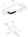
- FIG. 2 is a view explaining the cylindrical member 200 used for the electrode roll 600 according to the embodiment of the present invention.
- the cylindrical member 200 is a member formed into a cylindrical shape having a through hole 210 as illustrated.
- a material of the cylindrical member 200 is not especially limited as long as the cylindrical member 200 has a predetermined strength that resists deformation when the electrode is wound therearound under a tension and may be a metal, such as aluminum or a stainless steel, resin such as ABS or polycarbonate, plastic, paper, a material obtained by combining them or mixing fabrics. Among them, the resin or a reinforced plastic is preferable in terms of weight and strength and, for example, the cylindrical member 200 may be suitably formed of ABS resin.
- a width A of a peripheral surface 220 of the cylindrical member 200 around which the sheet-like electrode base material 500 is wound may be arbitrarily set.
- the width A of the peripheral surface 220, an outer diameter of the cylindrical member 200, and an inner diameter of the through hole 210 may be set to 800 mm, 180 mm ⁇ , and 150 mm ⁇ , respectively.
- the sheet-like electrode base material 500 having a width smaller than the width A of the peripheral surface 220 is wound around the thus configured cylindrical member 200, whereby the electrode roll is obtained.
- the cylindrical member 200 is repeatedly used, so that if the active material particles are adhered to the cylindrical member 200, they may be drawn in the sheet-like electrode base material 500 next time when the sheet-like electrode base material 500 is wound around the cylindrical member 200.
- the sheet-like electrode base material 500 is wound while pressing the active material particles, the following problems may occur: shapes of the active material particles are transferred onto the sheet-like electrode base material 500; the active material particles are adhered to the sheet-like electrode base material 500; and the sheet-like electrode base material 500 is damaged by the active material particles.
- a removable flexible film 400 is provided on the peripheral surface 220 of the cylindrical member 200, and then the sheet-like electrode base material 500 is wound on the removable flexible film 400.
- the active material particles are adhered to the flexible film 400 during repeated use of the cylindrical member 200, a part of the flexible film that corresponds to active material adhered portion is removed to expose a flexible film surface onto which the active material is not adhered, or the flexible film 400 itself is replaced with a new one.
- FIG. 3 is a view illustrating a manufacturing process of the electrode roll 600 according to the embodiment of the present invention.
- an adhesive portion for fixing the flexible film 400 to the cylindrical member 200 is provided in a width direction of the cylindrical member 200.
- the adhesive portion may be realized by application of a pasty material or double-sided tape.
- a double-sided tape 300 is preferably used.
- a dimension of the double-sided tape 300 is not especially limited as long as the flexible film can be fixed. For example, a length in the direction of the width A of the cylindrical member may be set to about 500 mm to 600 mm, and a tape width in a circumferential direction may be set to about 20 mm.
- FIG. 4 is a view schematically illustrating a cross section of the double-sided tape 300 used for the electrode roll 600 according to the embodiment of the present invention.
- the double-sided tape 300 includes a base material 310, a first adhesive layer 311, and a second adhesive layer 312.
- the base material is formed of PET, and first and second adhesive layers 311 and 312 are formed of acrylic adhesive applied onto front and back surfaces of the base material 310.
- the first and second adhesive layers 311 and 312 have different adhesive strengths. For example, when the first adhesive layer 311 is lower in adhesive strength than the second adhesive layer 312, the flexible film 400 is provided on the periphery of the cylindrical member 200 with the first adhesive layer 311 having a lower adhesive strength contacting the peripheral surface 220 of the cylindrical member 200 and second adhesive layer 312 having a higher adhesive strength contacting the flexible film 400.
- the double-sided tape 300 is easily peeled off from the peripheral surface 220 of the cylindrical member 200, thereby enhancing replaceability of the flexible film 400. Further, it is possible to eliminate disadvantage that a component of the first adhesive layer 311 remains on the peripheral surface 220 of the cylindrical member 200 when the double-sided tape 300 is peeled off from the peripheral surface 220 of the cylindrical member 200.
- the flexible film 400 may be formed of, e.g., paper, metal, resin, plastic, or the like and formed into a sheet of a thickness of about 5 ⁇ m to 1 mm. Considering dust-proof performance or handleability, it is preferable that a PET film is used as the flexible film 400 and that the thickness thereof is set to about 50 ⁇ m to 250 ⁇ m.
- a length in a width direction of the cylindrical member is preferably equal to or less than the width A of the cylindrical member, and a length in a circumferential direction of the cylindrical member is equal to or more than the circumferential length of the cylindrical member. Assuming that the width A of the peripheral surface 220 of the cylindrical member is 800 mm and that the outer diameter thereof is ⁇ 180, a 700 mm ⁇ 700 mm flexible film may be used.
- the first adhesive layer 311 of the double-sided tape 300 is stuck to the peripheral surface 220, and the second adhesive layer 312 is stuck to the flexible film 400. Then, as illustrated in FIG. 5 , the flexible film 400 is wound around the cylindrical member 200 by one or more turns, and a state illustrated in FIG. 6 is obtained, whereby preparation of winding the sheet-like electrode base material 500 around the cylindrical member 200 is completed.
- the sheet-like electrode base material 500 to be wound around the cylindrical member 200 is manufactured as follows.
- a composite material of lithiummanganate and lithium nickelate as the positive electrode active material, carbon black as a conductive agent, polyvinylidene fluoride as a binder, and N-methyl-2-pyrrolidone (NMP) solution as a solvent are mixed to prepare a positive electrode slurry.
- the thus prepared positive electrode slurry is intermittently or continuously applied onto both surfaces of an aluminum foil (thickness: 20 ⁇ m) as a positive electrode collector, followed by heating to remove the solvent, followed by pressuring with a roller so as to make the thickness of the sheet-like electrode base material 500 for positive electrode be about 200 ⁇ m.
- the sheet-like electrode base material 500 for negative electrode graphite powder as the negative electrode active material, polyvinylidene fluoride as a binder, and NMP solution as a solvent are mixed to prepare a negative electrode slurry. Then, the prepared negative electrode slurry is intermittently or continuously applied onto both surfaces of a copper foil as a negative electrode collector, followed by heating to remove the solvent, followed by pressuring with a roller.
- both the sheet-like electrode base material 500 for positive electrode and that for negative electrode can be used as the sheet-like electrode base material 500 to be wound around the electrode roll 600.
- FIG. 7 illustrates the electrode roll 600 according to the present invention obtained by winding the thus manufactured sheet-like electrode base material 500 around the cylindrical member 200.
- the electrode roll 600 thus obtained is attached to a not illustrated delivery device and a not illustrated cutting device. Then, for example, as illustrated in FIG. 8 , the sheet-like electrode base material 500 is cut along a line A-A' while being drawn in a direction of an arrow, followed by cutting along lines B-B', whereby the plurality of the sheet-like positive electrodes and plurality of the sheet-like negative electrodes used for the electrode laminate 60 of the unit battery 100 can be obtained.
- processing may be performed in which the sheet-like electrode base material 500 is cut along the B-B' line in a longitudinal direction thereof, followed by cutting along the A-A' line.
- the flexible film 400 is detachably provided on the peripheral surface 220 of the cylindrical member 200.
- the sheet-like electrode base material 500 even when particles of the positive electrode active material fall from the sheet-like electrode base material 500, it is possible to prevent a problem in that shapes of the active material particles that have fallen are transferred onto the sheet-like electrode base material 500 when the sheet-like electrode base material 500 is wound around the cylindrical member 200 to form irregularities in the active material, the adhered active material remaining on the sheet-like electrode base material 500, or sheet-like electrode base material 500 is damaged by the active material particles by removing a part of the flexible film 400 that corresponds to active material adhered portion to expose a flexible film surface onto which the active material is not adhered, or by replacing the flexible film 400 itself with a new one, thus providing an electrode roll manufacturing method capable of improving production efficiency.
- the double-sided tape 300 or flexible film 400 is stuck to the cylindrical member 200 and, thereby, a level difference is caused.
- the level difference is constant in both the width and length directions of the sheet-like base material, so that, unlike a local level difference caused due to foreign matters, it can be alleviated by winding a collector foil having no electrode active material on the innermost peripheral side of the electrode roll by one or more turns, thereby preventing adverse effect on battery characteristics or reliability.
- the electrode roll 600 of the present invention there can be provided the electrode roll 600 from which it is possible to manufacture a battery having stable electric characteristics and excellent in reliability while preventing shapes of the active material particles that have fallen from being transferred onto the sheet-like electrode base material 500 or preventing the sheet-like electrode base material 500 from being damaged by the active material particles.
- the electrode roll of the present invention even when the active material particles fall from the sheet-like electrode material, adverse effect caused by the particles can be eliminated by replacing the detachable flexible film with a new one, thereby improving production efficiency. Thus, the industrial applicability of the present invention is considerable.
Landscapes
- Engineering & Computer Science (AREA)
- Chemical & Material Sciences (AREA)
- Manufacturing & Machinery (AREA)
- Chemical Kinetics & Catalysis (AREA)
- Electrochemistry (AREA)
- General Chemical & Material Sciences (AREA)
- Materials Engineering (AREA)
- Battery Electrode And Active Subsutance (AREA)
- Secondary Cells (AREA)
Abstract
Description
- The present invention relates to an electrode roll used for manufacturing of a secondary unit battery such as a lithium ion battery and a manufacturing method thereof.
- Recently, as a solution for environmental problems, clean energy which can be obtained by wind power generation, solar power generation, or the like and can be used for household uses (for detached houses, etc.) or for industrial uses (for transport equipment, construction equipment, etc.) is attracting attention. However, the clean energy has a disadvantage in that output variation becomes large depending on the situation. For example, energy by the solar power generation can be obtained in the daytime where the sun is shining, while it cannot be obtained at night where the sun is down.
- To stabilize the output of the clean energy, technology that temporarily stores the clean energy in a battery is used. For example, solar energy thus stored in the battery becomes available at night where the sun is down. In general, a lead battery has been used as a battery for storing the clean energy; however, the lead battery has a disadvantage in that it is generally large in size and low in energy density.
- Thus, recently, a lithium ion secondary battery capable of operating at normal temperature and having a high energy density is attracting attention. In addition to the high energy density, the lithium ion secondary battery has a low impedance and is thus excellent in responsiveness.
- As an example of an internal structure of such a lithium ion secondary battery, there is known a structure in which an electrode laminate obtained by laminating a plurality of sheet-like positive electrodes and a plurality of sheet-like negative electrodes through separators and electrolyte are housed in a laminate film exterior material having a rectangular shape in a plan view (refer to, e.g., Patent Document 1).
[Patent Document 1]
JP2012-54198A - The sheet-like positive electrode or sheet-like negative electrode is cut out from a long sheet member (sheet-like electrode base material) serving as a base material thereof. The sheet-like electrode base material has an area larger than that of the sheet-like positive electrode or sheet-like negative electrode and has a predetermined width.
- The above sheet-like electrode base material is prepared in a state of being wound around a cylindrical member when being subjected to cut-out process.
- For example, a sheet-like electrode base material for positive electrode is obtained by applying a positive electrode active material composed of lithium manganate to both front and back surfaces of an aluminum base material. Here there is a problem in that while a sheet-like electrode base material having a width smaller than a width of the cylindrical member is wound around the cylindrical member or while the sheet-like electrode base material is delivered from the cylindrical member, particles of the positive electrode active material falling from the sheet-like electrode base material may be adhered to the cylindrical member.
- The cylindrical member is repeatedly used, so that if the active material particles are adhered to the cylindrical member, they may be drawn in the sheet-like electrode base material by static electricity or vibration next time when the sheet-like electrode base material is wound around the cylindrical member. When the sheet-like electrode base material is wound while pressing the active material particles, the following problems may occur: shapes of the active material particles are transferred onto the sheet-like electrode base material; the sheet-like electrode base material is subjected to lamination for formation of a battery with the active material adhered thereto; and the sheet-like electrode base material is damaged by the active material particles. As a result, the number of conforming articles of the electrode that can be cut out from the sheet-like electrode base material is reduced, thus deteriorating production efficiency.
- The present invention has been made to solve the above problem, and an electrode roll according to the present invention is an electrode roll in which a sheet-like electrode base material which is subjected to cutting to be an electrode used for an electrochemical element is rolled, including a resin cylindrical member having a peripheral surface with a predetermined width, a flexible film to be attached/detached with respect to the peripheral surface, and the sheet-like electrode base material wound on the flexible film.
- In the electrode roll according to the present invention, the flexible film is fixed onto the peripheral surface by a double-side tape.
- In the electrode roll according to the present invention, front and back adhesive layers of the double-sided tape have different adhesive strengths, and the adhesive layer having a lower adhesive strength is brought into contact with the peripheral surface.
- A manufacturing method according to the present invention is a manufacturing method for an electrode roll which is a sheet-like electrode base material which is subjected to cutting to be an electrode used for an electrochemical element and includes an attachment step of attaching a flexible film to a peripheral surface of a resin cylindrical member, the peripheral surface having a predetermined width, and a winding step of winding the sheet-like electrode base material on the flexible film.
- In the electrode roll manufacturing method according to the present invention, in the attachment step, the flexible film is fixed onto the peripheral surface by a double-side tape.
- In the electrode roll manufacturing method according to the present invention, front and back adhesive layers of the double-sided tape have different adhesive strengths, and the adhesive layer having a lower adhesive strength is brought into contact with the peripheral surface.
- According to the electrode roll of the present invention, the flexible film is detachably provided on the peripheral surface of the cylindrical member. Thus, even when particles of the positive electrode active material fall from the sheet-like electrode base material, it is possible to prevent, by replacing the flexible film with a new one, a problem in that shapes of the active material particles that have fallen are transferred onto the sheet-like electrode base material when the sheet-like electrode base material is wound around the cylindrical member, or sheet-like electrode base material is damaged by the active material particles, thereby improving production efficiency.
- Further, according to the electrode roll manufacturing method of the present invention, there can be provided the electrode roll from which it is possible to manufacture a battery having stable electric characteristics and excellent in reliability while preventing shapes of the active material particles that have fallen from being transferred onto the sheet-like electrode base material or preventing the sheet-like electrode base material from being damaged by the active material particles.
-
-
FIG. 1 is a view explaining an internal structure of aunit battery 100 manufactured using anelectrode roll 600 according to an embodiment of the present invention; -
FIG. 2 is a view explaining acylindrical member 200 used for theelectrode roll 600 according to the embodiment of the present invention; -
FIG. 3 is a view illustrating a manufacturing process of theelectrode roll 600 according to the embodiment of the present invention; -
FIG. 4 is a view schematically illustrating a cross section of a double-sided tape 300 used for theelectrode roll 600 according to the embodiment of the present invention; -
FIG. 5 is a view illustrating a manufacturing process of theelectrode roll 600 according to the embodiment of the present invention; -
FIG. 6 is a view illustrating a manufacturing process of theelectrode roll 600 according to the embodiment of the present invention; -
FIG. 7 is a view illustrating theelectrode roll 600 according to the embodiment of the present invention; and -
FIG. 8 is a view explaining a process of cutting a sheet-like electrode from theelectrode roll 600 according to the embodiment of the present invention. - An embodiment of the present invention will be described below with reference to the drawings.
FIG. 1 is a view explaining an internal structure of aunit battery 100 manufactured using an electrode roll according to the embodiment of the present invention. - In the present embodiment, as the
unit battery 100, a lithium ion secondary battery as a kind of an electrochemical element, in which lithium ion is moved between positive and negative electrode to perform charging and discharging is used. -
FIG. 1 is a perspective view illustrating theunit battery 100 in a partially transparent manner. - A
battery body 110 of theunit battery 100 has a structure in which anelectrode laminate 60 obtained by laminating a plurality of sheet-like positive electrodes and a plurality of sheet-like negative electrodes through separators and electrolyte (not illustrated) are housed in a laminate filmexterior material 90 having a rectangular shape in a plan view. - The sheet-like positive electrodes are each conductively connected to a positive electrode lead-out
tab 120 through a not illustrated collector. Similarly, the sheet-like negative electrodes are each conductively connected to a negative electrode lead-outtab 130 through a not illustrated collector. - The positive electrode lead-out
tab 120 and the negative electrode lead-outtab 130 are drawn, respectively, from one end portion (side) of thebattery body 110 and the other end portion (side) opposite to the one end portion. - The positive electrode lead-out
tab 120 and the negative electrode lead-outtab 130 each have a planar shape and are connected, inside the laminate filmexterior material 90, to the sheet-like positive electrodes and the sheet-like negative electrodes, respectively, directly or through a collector. - The laminate film
exterior material 90 is constituted by a metal laminate film having a heat sealing resin layer. More specifically, for example, two metal laminate film are put one over the other with the heat sealing resin layers facing each other to form the laminate filmexterior material 90, and an outer periphery of the laminate filmexterior material 90 is heat-sealed with theelectrode laminate 60 including the sheet-like positive electrodes, sheet-like negative electrodes, and separators and electrolyte housed inside the laminate filmexterior material 90, whereby the laminate filmexterior material 90 is internally hermetically sealed. - Here, a metal piece such as the positive electrode lead-out
tab 120 or the negative electrode lead-outtab 130 drawn from thebattery body 110 including the laminate filmexterior material 90 is referred to as "lead-out tab", and the sheet-like positive electrode or the sheet-like negative electrode laminated to each other through the separators inside the laminate filmexterior material 90 is referred to as "electrode". - The
electrode laminate 60 includes, in addition to the above electrode laminate obtained by laminating the plurality of sheet-like positive electrodes and plurality of sheet-like negative electrodes through the separators, an electrode laminate obtained by rolling and compressing a laminated body obtained by laminating the plurality of sheet-like positive electrodes and plurality of sheet-like negative electrodes through the separators. - Generally, in the
unit battery 100 as described above, aluminum or an aluminum alloy is used as a material of the positive electrode lead-outtab 120; and nickel, a material (nickel plating material (e.g., nickel-plated copper)) obtained by applying nickel-plating to metal other than the nickel, or a clad (nickel clad material (e.g., nickel-copper clad)) of nickel and metal other than the nickel is used as a material of the negative electrode lead-outtab 130. In the present embodiment, the positive electrode lead-outtab 120 is made of aluminum, and the negative electrode lead-outtab 130 is made of nickel-plated copper. - The following describes an
electrode roll 600 used in manufacturing process of theabove unit battery 100. - The
electrode roll 600 is obtained by winding, in a roll shape, a sheet-likeelectrode base material 500 serving as a base material from which the sheet-like positive or negative electrode used for theunit battery 100 is cut out. The sheet-likeelectrode base material 500 has an area larger than that of the individual sheet-like positive or negative electrode and has a predetermined width. Acylindrical member 200 is used for winding the sheet-likeelectrode base material 500. The electrode roll in the present invention refers to a body including not only the sheet-like electrode, but also the cylindrical member. -
FIG. 2 is a view explaining thecylindrical member 200 used for theelectrode roll 600 according to the embodiment of the present invention. - The
cylindrical member 200 is a member formed into a cylindrical shape having a throughhole 210 as illustrated. A material of thecylindrical member 200 is not especially limited as long as thecylindrical member 200 has a predetermined strength that resists deformation when the electrode is wound therearound under a tension and may be a metal, such as aluminum or a stainless steel, resin such as ABS or polycarbonate, plastic, paper, a material obtained by combining them or mixing fabrics. Among them, the resin or a reinforced plastic is preferable in terms of weight and strength and, for example, thecylindrical member 200 may be suitably formed of ABS resin. A width A of aperipheral surface 220 of thecylindrical member 200 around which the sheet-likeelectrode base material 500 is wound may be arbitrarily set. - For example, the width A of the
peripheral surface 220, an outer diameter of thecylindrical member 200, and an inner diameter of the throughhole 210 may be set to 800 mm, 180 mmϕ, and 150 mmϕ, respectively. - The sheet-like
electrode base material 500 having a width smaller than the width A of theperipheral surface 220 is wound around the thus configuredcylindrical member 200, whereby the electrode roll is obtained. - The
cylindrical member 200 is repeatedly used, so that if the active material particles are adhered to thecylindrical member 200, they may be drawn in the sheet-likeelectrode base material 500 next time when the sheet-likeelectrode base material 500 is wound around thecylindrical member 200. When the sheet-likeelectrode base material 500 is wound while pressing the active material particles, the following problems may occur: shapes of the active material particles are transferred onto the sheet-likeelectrode base material 500; the active material particles are adhered to the sheet-likeelectrode base material 500; and the sheet-likeelectrode base material 500 is damaged by the active material particles. - To prevent this, in the
electrode roll 600 according to the present invention, a removableflexible film 400 is provided on theperipheral surface 220 of thecylindrical member 200, and then the sheet-likeelectrode base material 500 is wound on the removableflexible film 400. - Thus, in the present invention, when the active material particles are adhered to the
flexible film 400 during repeated use of thecylindrical member 200, a part of the flexible film that corresponds to active material adhered portion is removed to expose a flexible film surface onto which the active material is not adhered, or theflexible film 400 itself is replaced with a new one. -
FIG. 3 is a view illustrating a manufacturing process of theelectrode roll 600 according to the embodiment of the present invention. As illustrated inFIG. 3 , before providing the removableflexible film 400 on theperipheral surface 220 of thecylindrical member 200, an adhesive portion for fixing theflexible film 400 to thecylindrical member 200 is provided in a width direction of thecylindrical member 200. The adhesive portion may be realized by application of a pasty material or double-sided tape. In terms of handling property to be described later, a double-sided tape 300 is preferably used. A dimension of the double-sided tape 300 is not especially limited as long as the flexible film can be fixed. For example, a length in the direction of the width A of the cylindrical member may be set to about 500 mm to 600 mm, and a tape width in a circumferential direction may be set to about 20 mm. - Front and back adhesive layers of the double-
side tape 300 used in manufacturing of theelectrode roll 600 preferably have different adhesive strengths.FIG. 4 is a view schematically illustrating a cross section of the double-sided tape 300 used for theelectrode roll 600 according to the embodiment of the present invention. - The double-
sided tape 300 includes abase material 310, a firstadhesive layer 311, and a secondadhesive layer 312. The base material is formed of PET, and first and secondadhesive layers base material 310. The first and secondadhesive layers adhesive layer 311 is lower in adhesive strength than the secondadhesive layer 312, theflexible film 400 is provided on the periphery of thecylindrical member 200 with the firstadhesive layer 311 having a lower adhesive strength contacting theperipheral surface 220 of thecylindrical member 200 and secondadhesive layer 312 having a higher adhesive strength contacting theflexible film 400. - With the above configuration, the double-
sided tape 300 is easily peeled off from theperipheral surface 220 of thecylindrical member 200, thereby enhancing replaceability of theflexible film 400. Further, it is possible to eliminate disadvantage that a component of the firstadhesive layer 311 remains on theperipheral surface 220 of thecylindrical member 200 when the double-sided tape 300 is peeled off from theperipheral surface 220 of thecylindrical member 200. - The
flexible film 400 may be formed of, e.g., paper, metal, resin, plastic, or the like and formed into a sheet of a thickness of about 5 µm to 1 mm. Considering dust-proof performance or handleability, it is preferable that a PET film is used as theflexible film 400 and that the thickness thereof is set to about 50 µm to 250 µm. As a dimension of theflexible film 400, a length in a width direction of the cylindrical member is preferably equal to or less than the width A of the cylindrical member, and a length in a circumferential direction of the cylindrical member is equal to or more than the circumferential length of the cylindrical member. Assuming that the width A of theperipheral surface 220 of the cylindrical member is 800 mm and that the outer diameter thereof is ϕ180, a 700 mm × 700 mm flexible film may be used. - The first
adhesive layer 311 of the double-sided tape 300 is stuck to theperipheral surface 220, and the secondadhesive layer 312 is stuck to theflexible film 400. Then, as illustrated inFIG. 5 , theflexible film 400 is wound around thecylindrical member 200 by one or more turns, and a state illustrated inFIG. 6 is obtained, whereby preparation of winding the sheet-likeelectrode base material 500 around thecylindrical member 200 is completed. - Taking the positive electrode as an example, the sheet-like
electrode base material 500 to be wound around thecylindrical member 200 is manufactured as follows. - First, a composite material of lithiummanganate and lithium nickelate as the positive electrode active material, carbon black as a conductive agent, polyvinylidene fluoride as a binder, and N-methyl-2-pyrrolidone (NMP) solution as a solvent are mixed to prepare a positive electrode slurry.
- The thus prepared positive electrode slurry is intermittently or continuously applied onto both surfaces of an aluminum foil (thickness: 20 µm) as a positive electrode collector, followed by heating to remove the solvent, followed by pressuring with a roller so as to make the thickness of the sheet-like
electrode base material 500 for positive electrode be about 200 µm. - On the other hand, in the case of the sheet-like
electrode base material 500 for negative electrode, graphite powder as the negative electrode active material, polyvinylidene fluoride as a binder, and NMP solution as a solvent are mixed to prepare a negative electrode slurry. Then, the prepared negative electrode slurry is intermittently or continuously applied onto both surfaces of a copper foil as a negative electrode collector, followed by heating to remove the solvent, followed by pressuring with a roller. - In the present invention, both the sheet-like
electrode base material 500 for positive electrode and that for negative electrode can be used as the sheet-likeelectrode base material 500 to be wound around theelectrode roll 600. -
FIG. 7 illustrates theelectrode roll 600 according to the present invention obtained by winding the thus manufactured sheet-likeelectrode base material 500 around thecylindrical member 200. - The
electrode roll 600 thus obtained is attached to a not illustrated delivery device and a not illustrated cutting device. Then, for example, as illustrated inFIG. 8 , the sheet-likeelectrode base material 500 is cut along a line A-A' while being drawn in a direction of an arrow, followed by cutting along lines B-B', whereby the plurality of the sheet-like positive electrodes and plurality of the sheet-like negative electrodes used for theelectrode laminate 60 of theunit battery 100 can be obtained. Alternatively, to obtain the plurality of sheet-like positive electrodes and plurality of sheet-like negative electrodes, processing may be performed in which the sheet-likeelectrode base material 500 is cut along the B-B' line in a longitudinal direction thereof, followed by cutting along the A-A' line. - According to the
electrode roll 600 of the present invention, theflexible film 400 is detachably provided on theperipheral surface 220 of thecylindrical member 200. Thus, even when particles of the positive electrode active material fall from the sheet-likeelectrode base material 500, it is possible to prevent a problem in that shapes of the active material particles that have fallen are transferred onto the sheet-likeelectrode base material 500 when the sheet-likeelectrode base material 500 is wound around thecylindrical member 200 to form irregularities in the active material, the adhered active material remaining on the sheet-likeelectrode base material 500, or sheet-likeelectrode base material 500 is damaged by the active material particles by removing a part of theflexible film 400 that corresponds to active material adhered portion to expose a flexible film surface onto which the active material is not adhered, or by replacing theflexible film 400 itself with a new one, thus providing an electrode roll manufacturing method capable of improving production efficiency. - In the present invention, the double-
sided tape 300 orflexible film 400 is stuck to thecylindrical member 200 and, thereby, a level difference is caused. However, the level difference is constant in both the width and length directions of the sheet-like base material, so that, unlike a local level difference caused due to foreign matters, it can be alleviated by winding a collector foil having no electrode active material on the innermost peripheral side of the electrode roll by one or more turns, thereby preventing adverse effect on battery characteristics or reliability. - Further, according to the manufacturing method of the
electrode roll 600 of the present invention, there can be provided theelectrode roll 600 from which it is possible to manufacture a battery having stable electric characteristics and excellent in reliability while preventing shapes of the active material particles that have fallen from being transferred onto the sheet-likeelectrode base material 500 or preventing the sheet-likeelectrode base material 500 from being damaged by the active material particles. - According to the electrode roll of the present invention, even when the active material particles fall from the sheet-like electrode material, adverse effect caused by the particles can be eliminated by replacing the detachable flexible film with a new one, thereby improving production efficiency. Thus, the industrial applicability of the present invention is considerable.
-
- 60: Electrode laminate
- 90: Laminate film exterior material
- 100: Unit battery
- 110: Battery main body
- 120: Positive electrode lead-out tab
- 130: Negative electrode lead-out tab
- 200: Cylindrical member
- 210: Through hole
- 220: Peripheral surface
- 300: Double-side tape
- 310: Base material
- 311: First adhesive layer
- 312: Second adhesive layer
- 400: Flexible film
- 500: Sheet-like electrode base material
- 600: Electrode roll
Claims (6)
- An electrode roll in which a sheet-like electrode base material which is subjected to cutting to be an electrode used for an electrochemical element is rolled, characterized by comprising:a resin cylindrical member having a peripheral surface with a predetermined width;a flexible film to be attached/detached with respect to the peripheral surface; andthe sheet-like electrode base material wound on the flexible film.
- The electrode roll according to claim 1, characterized in that
the flexible film is fixed onto the peripheral surface by a double-sided tape. - The electrode roll according to claim 2, characterized in that
front and back adhesive layers of the double-sided tape have different adhesive strengths, and
the adhesive layer having a lower adhesive strength is brought into contact with the peripheral surface. - A manufacturing method for an electrode roll in which a sheet-like electrode base material which is subjected to cutting to be an electrode used for an electrochemical element is rolled, characterized by comprising:an attachment step of attaching a flexible film to a peripheral surface of a resin cylindrical member, the peripheral surface having a predetermined width; anda winding step of winding the sheet-like electrode base material on the flexible film.
- The electrode roll manufacturing method according to claim 4, characterized in that
in the attachment step, the flexible film is fixed onto the peripheral surface by a double-sided tape. - The electrode roll manufacturing method according to claim 5, characterized in that
front and back adhesive layers of the double-sided tape have different adhesive strengths, and
the adhesive layer having a lower adhesive strength is brought into contact with the peripheral surface.
Applications Claiming Priority (2)
| Application Number | Priority Date | Filing Date | Title |
|---|---|---|---|
| JP2012200371 | 2012-09-12 | ||
| PCT/JP2013/071336 WO2014041928A1 (en) | 2012-09-12 | 2013-08-07 | Electrode roll and method for producing electrode roll |
Publications (3)
| Publication Number | Publication Date |
|---|---|
| EP2897199A1 true EP2897199A1 (en) | 2015-07-22 |
| EP2897199A4 EP2897199A4 (en) | 2016-05-18 |
| EP2897199B1 EP2897199B1 (en) | 2024-06-26 |
Family
ID=50278054
Family Applications (1)
| Application Number | Title | Priority Date | Filing Date |
|---|---|---|---|
| EP13837998.7A Active EP2897199B1 (en) | 2012-09-12 | 2013-08-07 | Electrode roll and method for producing electrode roll |
Country Status (6)
| Country | Link |
|---|---|
| US (1) | US10424808B2 (en) |
| EP (1) | EP2897199B1 (en) |
| JP (2) | JP6202631B2 (en) |
| CN (1) | CN104620422B (en) |
| ES (1) | ES2983247T3 (en) |
| WO (1) | WO2014041928A1 (en) |
Families Citing this family (8)
| Publication number | Priority date | Publication date | Assignee | Title |
|---|---|---|---|---|
| KR102402804B1 (en) * | 2015-12-11 | 2022-05-27 | 히타치 긴조쿠 가부시키가이샤 | Electrode device and method for manufacturing metal foil using same |
| US11830672B2 (en) | 2016-11-23 | 2023-11-28 | KYOCERA AVX Components Corporation | Ultracapacitor for use in a solder reflow process |
| KR102104297B1 (en) * | 2016-11-30 | 2020-04-24 | 주식회사 엘지화학 | Device of Cleaning Protect Film for Preparation of Battery Cell Comprising Cleaning Roll |
| KR102501413B1 (en) * | 2021-06-23 | 2023-02-21 | 서정탁 | Tape having different adhesive strength on both sides and bulletin board using the same |
| EP4358205A4 (en) * | 2021-10-19 | 2025-02-19 | LG Energy Solution, Ltd. | ROLLER TYPE ELECTRODE BODY |
| CN117120353B (en) * | 2022-02-14 | 2026-01-02 | 株式会社Lg新能源 | Electrode connection membrane winding device, winding method and electrode roll |
| WO2024196498A1 (en) * | 2023-03-22 | 2024-09-26 | Zeta Energy Llc | Composite electrode roll for electrochemical cells |
| KR20250049638A (en) * | 2023-10-05 | 2025-04-14 | 주식회사 엘지에너지솔루션 | How to replace bobbins |
Family Cites Families (26)
| Publication number | Priority date | Publication date | Assignee | Title |
|---|---|---|---|---|
| JPS63228565A (en) * | 1987-03-17 | 1988-09-22 | Sanyo Electric Co Ltd | Manufacture of cartridge cell |
| JPH11144763A (en) | 1997-11-05 | 1999-05-28 | Toray Ind Inc | Battery |
| JP4714952B2 (en) | 1998-10-30 | 2011-07-06 | ソニー株式会社 | Lithium ion polymer secondary battery, manufacturing apparatus and manufacturing method thereof |
| US6145777A (en) | 1999-04-28 | 2000-11-14 | 3M Innovative Properties Company | Single station continuous log roll winder |
| JP2000345113A (en) | 1999-06-07 | 2000-12-12 | Toyo Ink Mfg Co Ltd | Double-sided tape and manufacturing method thereof |
| JP4617625B2 (en) | 2001-08-31 | 2011-01-26 | 宇部興産株式会社 | Winding core |
| JP2003242970A (en) | 2002-02-12 | 2003-08-29 | Japan Storage Battery Co Ltd | Battery |
| JP4737924B2 (en) | 2003-08-11 | 2011-08-03 | ノードソン コーポレーション | ELECTROLYTE MEMBRANE FOR FUEL CELL, ELECTROLYTE MEMBRANE COMPOSITION, METHOD FOR PRODUCING ROLL STOCK OF ELECTROLYTE MEMBRANE COMPOSITION, METHOD FOR PRODUCING ELECTROLYTE MEMBRANE / electrode assembly FOR FUEL CELL, AND METHOD FOR PRODUCING FUEL CELL |
| JP4522680B2 (en) | 2003-09-25 | 2010-08-11 | 大日本印刷株式会社 | Electrode plate tape roll manufacturing method |
| US7078082B2 (en) | 2004-01-15 | 2006-07-18 | Sonoco Development, Inc. | Dual-functioning mechanism for startup during winding of web material and for splicing during unwinding |
| JP2005255225A (en) | 2004-03-12 | 2005-09-22 | Dainippon Printing Co Ltd | Tape roll package and manufacturing method thereof |
| US20090065426A1 (en) | 2006-03-13 | 2009-03-12 | Nitto Denko Corporation | Spiral membrane element |
| KR100772265B1 (en) | 2006-03-15 | 2007-11-01 | 엘에스전선 주식회사 | Bobbin device for thin film winding and winding method of thin film using same |
| CN101501156A (en) | 2006-08-11 | 2009-08-05 | 日东电工株式会社 | Double-faced pressure-sensitive adhesive tape or sheet and roll of continuous strip |
| JP5135751B2 (en) | 2006-09-29 | 2013-02-06 | 大日本印刷株式会社 | Double-sided tape |
| JP4954129B2 (en) * | 2008-03-18 | 2012-06-13 | シーケーディ株式会社 | Method for manufacturing wound element |
| JP4964821B2 (en) | 2008-04-21 | 2012-07-04 | シーケーディ株式会社 | Winding device and winding element manufacturing method |
| CN101486850A (en) | 2009-02-09 | 2009-07-22 | 屠尖兵 | Two-faced adhesive tape and production method thereof |
| CN201397858Y (en) | 2009-03-26 | 2010-02-03 | 天津力神电池股份有限公司 | Novel square lithium ion battery capable of preventing glue overflow |
| EP2273601B1 (en) * | 2009-07-08 | 2018-05-23 | Samsung SDI Co., Ltd. | Secondary battery and production method thereof |
| JP2011252095A (en) * | 2010-06-02 | 2011-12-15 | Nitto Denko Corp | Double-coated pressure-sensitive adhesive tape |
| JP5717168B2 (en) | 2010-09-03 | 2015-05-13 | Necエナジーデバイス株式会社 | Negative electrode for nonaqueous electrolyte secondary battery, method for producing the same, and nonaqueous electrolyte secondary battery |
| CN201868529U (en) * | 2010-11-06 | 2011-06-15 | 合肥国轩高科动力能源有限公司 | Needle winding device for battery cell winding and hollow support tube used in conjunction with the winding needle |
| CN102079466A (en) | 2011-03-02 | 2011-06-01 | 深圳市三利谱光电科技股份有限公司 | Winding core covered with soft material |
| JP5595309B2 (en) | 2011-03-14 | 2014-09-24 | Ckd株式会社 | Winding device |
| CN102290607B (en) | 2011-06-27 | 2013-11-20 | 深圳市吉阳自动化科技有限公司 | Electrode plate-winding method and electrode plate winder |
-
2013
- 2013-08-07 US US14/420,577 patent/US10424808B2/en active Active
- 2013-08-07 ES ES13837998T patent/ES2983247T3/en active Active
- 2013-08-07 CN CN201380047326.3A patent/CN104620422B/en active Active
- 2013-08-07 EP EP13837998.7A patent/EP2897199B1/en active Active
- 2013-08-07 JP JP2014535448A patent/JP6202631B2/en active Active
- 2013-08-07 WO PCT/JP2013/071336 patent/WO2014041928A1/en not_active Ceased
-
2017
- 2017-08-04 JP JP2017151707A patent/JP6410331B2/en active Active
Also Published As
| Publication number | Publication date |
|---|---|
| JP6410331B2 (en) | 2018-10-24 |
| EP2897199B1 (en) | 2024-06-26 |
| EP2897199A4 (en) | 2016-05-18 |
| JPWO2014041928A1 (en) | 2016-08-18 |
| CN104620422A (en) | 2015-05-13 |
| CN104620422B (en) | 2018-06-29 |
| JP2017195207A (en) | 2017-10-26 |
| JP6202631B2 (en) | 2017-09-27 |
| US10424808B2 (en) | 2019-09-24 |
| ES2983247T3 (en) | 2024-10-22 |
| US20150200416A1 (en) | 2015-07-16 |
| WO2014041928A1 (en) | 2014-03-20 |
Similar Documents
| Publication | Publication Date | Title |
|---|---|---|
| EP2897199B1 (en) | Electrode roll and method for producing electrode roll | |
| US8956748B2 (en) | Battery | |
| CN111816909B (en) | Solid electrolyte sheet, all-solid battery, separator and lithium ion battery | |
| KR102426165B1 (en) | Electrical storage device and manufacturing method thereof | |
| CN108808059B (en) | Laminated secondary battery based on cross stacking and preparation method thereof | |
| US10777782B2 (en) | Thin electrochemical cell | |
| KR102303986B1 (en) | Thin type power storage device and method of manufacturing therof | |
| JP7220617B2 (en) | ALL-SOLID BATTERY AND METHOD FOR MANUFACTURING ALL-SOLID BATTERY | |
| EP2487747A2 (en) | Electrode assembly for a battery and method for manufacturing same | |
| JP4025930B2 (en) | Battery manufacturing method | |
| CN108376759A (en) | A kind of soft package lithium battery preparation method improving energy density | |
| KR101917661B1 (en) | Semi-automatic method for manufacturing an electrochemical Li-ion battery | |
| CN207861532U (en) | Secondary cell manufacture material attachment device | |
| JP7061588B2 (en) | Manufacturing method of all-solid-state battery and all-solid-state battery | |
| TW201419628A (en) | Electrode group, preparation method of electrode group, and electrochemical battery including electrode group | |
| CN111816926A (en) | Electrode group for battery, wound-type battery provided with the electrode group, and method for producing the electrode group for battery | |
| JP2012212506A (en) | Laminate type battery | |
| US10833370B2 (en) | Battery and battery manufacturing method | |
| WO2020007130A1 (en) | Negative electrode plate for lithium battery, and lithium battery | |
| CN111602280A (en) | Method for preparing electrochemical stack of metal ion battery using gel polymer electrolyte membrane and related battery | |
| JP2011150974A (en) | Electrode body, and method for manufacturing the same | |
| JP2020102311A (en) | Wound battery and method of manufacturing wound battery | |
| CN109088090B (en) | Button cell with winding mode and manufacturing method thereof | |
| JP4010521B2 (en) | Stacked battery | |
| CN108400386A (en) | Improve the preparation method of the flexible battery of bending property |
Legal Events
| Date | Code | Title | Description |
|---|---|---|---|
| PUAI | Public reference made under article 153(3) epc to a published international application that has entered the european phase |
Free format text: ORIGINAL CODE: 0009012 |
|
| 17P | Request for examination filed |
Effective date: 20150318 |
|
| AK | Designated contracting states |
Kind code of ref document: A1 Designated state(s): AL AT BE BG CH CY CZ DE DK EE ES FI FR GB GR HR HU IE IS IT LI LT LU LV MC MK MT NL NO PL PT RO RS SE SI SK SM TR |
|
| AX | Request for extension of the european patent |
Extension state: BA ME |
|
| DAX | Request for extension of the european patent (deleted) | ||
| RA4 | Supplementary search report drawn up and despatched (corrected) |
Effective date: 20160420 |
|
| RIC1 | Information provided on ipc code assigned before grant |
Ipc: H01M 4/139 20100101ALI20160414BHEP Ipc: H01M 4/04 20060101ALI20160414BHEP Ipc: H01M 4/88 20060101AFI20160414BHEP Ipc: H01M 4/13 20100101ALI20160414BHEP Ipc: H01M 4/02 20060101ALI20160414BHEP |
|
| STAA | Information on the status of an ep patent application or granted ep patent |
Free format text: STATUS: EXAMINATION IS IN PROGRESS |
|
| 17Q | First examination report despatched |
Effective date: 20180201 |
|
| RAP1 | Party data changed (applicant data changed or rights of an application transferred) |
Owner name: ENVISION AESC ENERGY DEVICES LTD. |
|
| P01 | Opt-out of the competence of the unified patent court (upc) registered |
Effective date: 20230428 |
|
| GRAP | Despatch of communication of intention to grant a patent |
Free format text: ORIGINAL CODE: EPIDOSNIGR1 |
|
| STAA | Information on the status of an ep patent application or granted ep patent |
Free format text: STATUS: GRANT OF PATENT IS INTENDED |
|
| RIC1 | Information provided on ipc code assigned before grant |
Ipc: H01M 10/0525 20100101ALI20240119BHEP Ipc: H01M 4/02 20060101ALI20240119BHEP Ipc: H01M 4/13 20100101ALI20240119BHEP Ipc: H01M 4/139 20100101ALI20240119BHEP Ipc: H01M 4/04 20060101ALI20240119BHEP Ipc: H01M 4/88 20060101AFI20240119BHEP |
|
| INTG | Intention to grant announced |
Effective date: 20240219 |
|
| P02 | Opt-out of the competence of the unified patent court (upc) changed |
Effective date: 20240326 |
|
| RAP1 | Party data changed (applicant data changed or rights of an application transferred) |
Owner name: AESC JAPAN LTD. |
|
| GRAS | Grant fee paid |
Free format text: ORIGINAL CODE: EPIDOSNIGR3 |
|
| GRAA | (expected) grant |
Free format text: ORIGINAL CODE: 0009210 |
|
| STAA | Information on the status of an ep patent application or granted ep patent |
Free format text: STATUS: THE PATENT HAS BEEN GRANTED |
|
| AK | Designated contracting states |
Kind code of ref document: B1 Designated state(s): AL AT BE BG CH CY CZ DE DK EE ES FI FR GB GR HR HU IE IS IT LI LT LU LV MC MK MT NL NO PL PT RO RS SE SI SK SM TR |
|
| REG | Reference to a national code |
Ref country code: GB Ref legal event code: FG4D |
|
| REG | Reference to a national code |
Ref country code: CH Ref legal event code: EP |
|
| REG | Reference to a national code |
Ref country code: DE Ref legal event code: R096 Ref document number: 602013085840 Country of ref document: DE |
|
| PG25 | Lapsed in a contracting state [announced via postgrant information from national office to epo] |
Ref country code: BG Free format text: LAPSE BECAUSE OF FAILURE TO SUBMIT A TRANSLATION OF THE DESCRIPTION OR TO PAY THE FEE WITHIN THE PRESCRIBED TIME-LIMIT Effective date: 20240626 |
|
| PG25 | Lapsed in a contracting state [announced via postgrant information from national office to epo] |
Ref country code: HR Free format text: LAPSE BECAUSE OF FAILURE TO SUBMIT A TRANSLATION OF THE DESCRIPTION OR TO PAY THE FEE WITHIN THE PRESCRIBED TIME-LIMIT Effective date: 20240626 Ref country code: FI Free format text: LAPSE BECAUSE OF FAILURE TO SUBMIT A TRANSLATION OF THE DESCRIPTION OR TO PAY THE FEE WITHIN THE PRESCRIBED TIME-LIMIT Effective date: 20240626 |
|
| REG | Reference to a national code |
Ref country code: LT Ref legal event code: MG9D |
|
| PG25 | Lapsed in a contracting state [announced via postgrant information from national office to epo] |
Ref country code: GR Free format text: LAPSE BECAUSE OF FAILURE TO SUBMIT A TRANSLATION OF THE DESCRIPTION OR TO PAY THE FEE WITHIN THE PRESCRIBED TIME-LIMIT Effective date: 20240927 |
|
| REG | Reference to a national code |
Ref country code: ES Ref legal event code: FG2A Ref document number: 2983247 Country of ref document: ES Kind code of ref document: T3 Effective date: 20241022 |
|
| PG25 | Lapsed in a contracting state [announced via postgrant information from national office to epo] |
Ref country code: LV Free format text: LAPSE BECAUSE OF FAILURE TO SUBMIT A TRANSLATION OF THE DESCRIPTION OR TO PAY THE FEE WITHIN THE PRESCRIBED TIME-LIMIT Effective date: 20240626 |
|
| REG | Reference to a national code |
Ref country code: NL Ref legal event code: MP Effective date: 20240626 |
|
| PG25 | Lapsed in a contracting state [announced via postgrant information from national office to epo] |
Ref country code: NO Free format text: LAPSE BECAUSE OF FAILURE TO SUBMIT A TRANSLATION OF THE DESCRIPTION OR TO PAY THE FEE WITHIN THE PRESCRIBED TIME-LIMIT Effective date: 20240926 Ref country code: LV Free format text: LAPSE BECAUSE OF FAILURE TO SUBMIT A TRANSLATION OF THE DESCRIPTION OR TO PAY THE FEE WITHIN THE PRESCRIBED TIME-LIMIT Effective date: 20240626 Ref country code: HR Free format text: LAPSE BECAUSE OF FAILURE TO SUBMIT A TRANSLATION OF THE DESCRIPTION OR TO PAY THE FEE WITHIN THE PRESCRIBED TIME-LIMIT Effective date: 20240626 Ref country code: GR Free format text: LAPSE BECAUSE OF FAILURE TO SUBMIT A TRANSLATION OF THE DESCRIPTION OR TO PAY THE FEE WITHIN THE PRESCRIBED TIME-LIMIT Effective date: 20240927 Ref country code: FI Free format text: LAPSE BECAUSE OF FAILURE TO SUBMIT A TRANSLATION OF THE DESCRIPTION OR TO PAY THE FEE WITHIN THE PRESCRIBED TIME-LIMIT Effective date: 20240626 Ref country code: BG Free format text: LAPSE BECAUSE OF FAILURE TO SUBMIT A TRANSLATION OF THE DESCRIPTION OR TO PAY THE FEE WITHIN THE PRESCRIBED TIME-LIMIT Effective date: 20240626 Ref country code: RS Free format text: LAPSE BECAUSE OF FAILURE TO SUBMIT A TRANSLATION OF THE DESCRIPTION OR TO PAY THE FEE WITHIN THE PRESCRIBED TIME-LIMIT Effective date: 20240926 |
|
| PG25 | Lapsed in a contracting state [announced via postgrant information from national office to epo] |
Ref country code: NL Free format text: LAPSE BECAUSE OF FAILURE TO SUBMIT A TRANSLATION OF THE DESCRIPTION OR TO PAY THE FEE WITHIN THE PRESCRIBED TIME-LIMIT Effective date: 20240626 |
|
| REG | Reference to a national code |
Ref country code: AT Ref legal event code: MK05 Ref document number: 1698461 Country of ref document: AT Kind code of ref document: T Effective date: 20240626 |
|
| PG25 | Lapsed in a contracting state [announced via postgrant information from national office to epo] |
Ref country code: NL Free format text: LAPSE BECAUSE OF FAILURE TO SUBMIT A TRANSLATION OF THE DESCRIPTION OR TO PAY THE FEE WITHIN THE PRESCRIBED TIME-LIMIT Effective date: 20240626 |
|
| PG25 | Lapsed in a contracting state [announced via postgrant information from national office to epo] |
Ref country code: PT Free format text: LAPSE BECAUSE OF FAILURE TO SUBMIT A TRANSLATION OF THE DESCRIPTION OR TO PAY THE FEE WITHIN THE PRESCRIBED TIME-LIMIT Effective date: 20241028 |
|
| PG25 | Lapsed in a contracting state [announced via postgrant information from national office to epo] |
Ref country code: PT Free format text: LAPSE BECAUSE OF FAILURE TO SUBMIT A TRANSLATION OF THE DESCRIPTION OR TO PAY THE FEE WITHIN THE PRESCRIBED TIME-LIMIT Effective date: 20241028 |
|
| PG25 | Lapsed in a contracting state [announced via postgrant information from national office to epo] |
Ref country code: PL Free format text: LAPSE BECAUSE OF FAILURE TO SUBMIT A TRANSLATION OF THE DESCRIPTION OR TO PAY THE FEE WITHIN THE PRESCRIBED TIME-LIMIT Effective date: 20240626 |
|
| PG25 | Lapsed in a contracting state [announced via postgrant information from national office to epo] |
Ref country code: EE Free format text: LAPSE BECAUSE OF FAILURE TO SUBMIT A TRANSLATION OF THE DESCRIPTION OR TO PAY THE FEE WITHIN THE PRESCRIBED TIME-LIMIT Effective date: 20240626 |
|
| PG25 | Lapsed in a contracting state [announced via postgrant information from national office to epo] |
Ref country code: AT Free format text: LAPSE BECAUSE OF FAILURE TO SUBMIT A TRANSLATION OF THE DESCRIPTION OR TO PAY THE FEE WITHIN THE PRESCRIBED TIME-LIMIT Effective date: 20240626 Ref country code: IS Free format text: LAPSE BECAUSE OF FAILURE TO SUBMIT A TRANSLATION OF THE DESCRIPTION OR TO PAY THE FEE WITHIN THE PRESCRIBED TIME-LIMIT Effective date: 20241026 |
|
| PG25 | Lapsed in a contracting state [announced via postgrant information from national office to epo] |
Ref country code: CZ Free format text: LAPSE BECAUSE OF FAILURE TO SUBMIT A TRANSLATION OF THE DESCRIPTION OR TO PAY THE FEE WITHIN THE PRESCRIBED TIME-LIMIT Effective date: 20240626 |
|
| PG25 | Lapsed in a contracting state [announced via postgrant information from national office to epo] |
Ref country code: RO Free format text: LAPSE BECAUSE OF FAILURE TO SUBMIT A TRANSLATION OF THE DESCRIPTION OR TO PAY THE FEE WITHIN THE PRESCRIBED TIME-LIMIT Effective date: 20240626 Ref country code: SK Free format text: LAPSE BECAUSE OF FAILURE TO SUBMIT A TRANSLATION OF THE DESCRIPTION OR TO PAY THE FEE WITHIN THE PRESCRIBED TIME-LIMIT Effective date: 20240626 |
|
| PG25 | Lapsed in a contracting state [announced via postgrant information from national office to epo] |
Ref country code: SM Free format text: LAPSE BECAUSE OF FAILURE TO SUBMIT A TRANSLATION OF THE DESCRIPTION OR TO PAY THE FEE WITHIN THE PRESCRIBED TIME-LIMIT Effective date: 20240626 |
|
| PG25 | Lapsed in a contracting state [announced via postgrant information from national office to epo] |
Ref country code: SM Free format text: LAPSE BECAUSE OF FAILURE TO SUBMIT A TRANSLATION OF THE DESCRIPTION OR TO PAY THE FEE WITHIN THE PRESCRIBED TIME-LIMIT Effective date: 20240626 Ref country code: SK Free format text: LAPSE BECAUSE OF FAILURE TO SUBMIT A TRANSLATION OF THE DESCRIPTION OR TO PAY THE FEE WITHIN THE PRESCRIBED TIME-LIMIT Effective date: 20240626 Ref country code: RO Free format text: LAPSE BECAUSE OF FAILURE TO SUBMIT A TRANSLATION OF THE DESCRIPTION OR TO PAY THE FEE WITHIN THE PRESCRIBED TIME-LIMIT Effective date: 20240626 Ref country code: PL Free format text: LAPSE BECAUSE OF FAILURE TO SUBMIT A TRANSLATION OF THE DESCRIPTION OR TO PAY THE FEE WITHIN THE PRESCRIBED TIME-LIMIT Effective date: 20240626 Ref country code: IS Free format text: LAPSE BECAUSE OF FAILURE TO SUBMIT A TRANSLATION OF THE DESCRIPTION OR TO PAY THE FEE WITHIN THE PRESCRIBED TIME-LIMIT Effective date: 20241026 Ref country code: EE Free format text: LAPSE BECAUSE OF FAILURE TO SUBMIT A TRANSLATION OF THE DESCRIPTION OR TO PAY THE FEE WITHIN THE PRESCRIBED TIME-LIMIT Effective date: 20240626 Ref country code: CZ Free format text: LAPSE BECAUSE OF FAILURE TO SUBMIT A TRANSLATION OF THE DESCRIPTION OR TO PAY THE FEE WITHIN THE PRESCRIBED TIME-LIMIT Effective date: 20240626 Ref country code: AT Free format text: LAPSE BECAUSE OF FAILURE TO SUBMIT A TRANSLATION OF THE DESCRIPTION OR TO PAY THE FEE WITHIN THE PRESCRIBED TIME-LIMIT Effective date: 20240626 |
|
| PG25 | Lapsed in a contracting state [announced via postgrant information from national office to epo] |
Ref country code: IT Free format text: LAPSE BECAUSE OF FAILURE TO SUBMIT A TRANSLATION OF THE DESCRIPTION OR TO PAY THE FEE WITHIN THE PRESCRIBED TIME-LIMIT Effective date: 20240626 |
|
| REG | Reference to a national code |
Ref country code: DE Ref legal event code: R097 Ref document number: 602013085840 Country of ref document: DE |
|
| REG | Reference to a national code |
Ref country code: CH Ref legal event code: PL |
|
| PG25 | Lapsed in a contracting state [announced via postgrant information from national office to epo] |
Ref country code: DK Free format text: LAPSE BECAUSE OF FAILURE TO SUBMIT A TRANSLATION OF THE DESCRIPTION OR TO PAY THE FEE WITHIN THE PRESCRIBED TIME-LIMIT Effective date: 20240626 |
|
| PG25 | Lapsed in a contracting state [announced via postgrant information from national office to epo] |
Ref country code: LU Free format text: LAPSE BECAUSE OF NON-PAYMENT OF DUE FEES Effective date: 20240807 |
|
| PG25 | Lapsed in a contracting state [announced via postgrant information from national office to epo] |
Ref country code: MC Free format text: LAPSE BECAUSE OF FAILURE TO SUBMIT A TRANSLATION OF THE DESCRIPTION OR TO PAY THE FEE WITHIN THE PRESCRIBED TIME-LIMIT Effective date: 20240626 Ref country code: CH Free format text: LAPSE BECAUSE OF NON-PAYMENT OF DUE FEES Effective date: 20240831 |
|
| PLBE | No opposition filed within time limit |
Free format text: ORIGINAL CODE: 0009261 |
|
| STAA | Information on the status of an ep patent application or granted ep patent |
Free format text: STATUS: NO OPPOSITION FILED WITHIN TIME LIMIT |
|
| 26N | No opposition filed |
Effective date: 20250327 |
|
| REG | Reference to a national code |
Ref country code: BE Ref legal event code: MM Effective date: 20240831 |
|
| PGFP | Annual fee paid to national office [announced via postgrant information from national office to epo] |
Ref country code: GB Payment date: 20250626 Year of fee payment: 13 |
|
| PG25 | Lapsed in a contracting state [announced via postgrant information from national office to epo] |
Ref country code: BE Free format text: LAPSE BECAUSE OF NON-PAYMENT OF DUE FEES Effective date: 20240831 |
|
| PGFP | Annual fee paid to national office [announced via postgrant information from national office to epo] |
Ref country code: FR Payment date: 20250623 Year of fee payment: 13 |
|
| PG25 | Lapsed in a contracting state [announced via postgrant information from national office to epo] |
Ref country code: IE Free format text: LAPSE BECAUSE OF NON-PAYMENT OF DUE FEES Effective date: 20240807 |
|
| PG25 | Lapsed in a contracting state [announced via postgrant information from national office to epo] |
Ref country code: SE Free format text: LAPSE BECAUSE OF FAILURE TO SUBMIT A TRANSLATION OF THE DESCRIPTION OR TO PAY THE FEE WITHIN THE PRESCRIBED TIME-LIMIT Effective date: 20240626 |
|
| PGFP | Annual fee paid to national office [announced via postgrant information from national office to epo] |
Ref country code: ES Payment date: 20250905 Year of fee payment: 13 |
|
| PGFP | Annual fee paid to national office [announced via postgrant information from national office to epo] |
Ref country code: DE Payment date: 20250624 Year of fee payment: 13 |
|
| PG25 | Lapsed in a contracting state [announced via postgrant information from national office to epo] |
Ref country code: CY Free format text: LAPSE BECAUSE OF FAILURE TO SUBMIT A TRANSLATION OF THE DESCRIPTION OR TO PAY THE FEE WITHIN THE PRESCRIBED TIME-LIMIT; INVALID AB INITIO Effective date: 20130807 |
|
| PG25 | Lapsed in a contracting state [announced via postgrant information from national office to epo] |
Ref country code: HU Free format text: LAPSE BECAUSE OF FAILURE TO SUBMIT A TRANSLATION OF THE DESCRIPTION OR TO PAY THE FEE WITHIN THE PRESCRIBED TIME-LIMIT; INVALID AB INITIO Effective date: 20130807 |