EP2896951A1 - Vehicle drive system testing apparatus - Google Patents
Vehicle drive system testing apparatus Download PDFInfo
- Publication number
- EP2896951A1 EP2896951A1 EP14004392.8A EP14004392A EP2896951A1 EP 2896951 A1 EP2896951 A1 EP 2896951A1 EP 14004392 A EP14004392 A EP 14004392A EP 2896951 A1 EP2896951 A1 EP 2896951A1
- Authority
- EP
- European Patent Office
- Prior art keywords
- operation amount
- input part
- amount input
- drive system
- vehicle drive
- Prior art date
- Legal status (The legal status is an assumption and is not a legal conclusion. Google has not performed a legal analysis and makes no representation as to the accuracy of the status listed.)
- Granted
Links
Images

Classifications
-
- G—PHYSICS
- G01—MEASURING; TESTING
- G01M—TESTING STATIC OR DYNAMIC BALANCE OF MACHINES OR STRUCTURES; TESTING OF STRUCTURES OR APPARATUS, NOT OTHERWISE PROVIDED FOR
- G01M13/00—Testing of machine parts
- G01M13/02—Gearings; Transmission mechanisms
- G01M13/025—Test-benches with rotational drive means and loading means; Load or drive simulation
-
- B—PERFORMING OPERATIONS; TRANSPORTING
- B60—VEHICLES IN GENERAL
- B60K—ARRANGEMENT OR MOUNTING OF PROPULSION UNITS OR OF TRANSMISSIONS IN VEHICLES; ARRANGEMENT OR MOUNTING OF PLURAL DIVERSE PRIME-MOVERS IN VEHICLES; AUXILIARY DRIVES FOR VEHICLES; INSTRUMENTATION OR DASHBOARDS FOR VEHICLES; ARRANGEMENTS IN CONNECTION WITH COOLING, AIR INTAKE, GAS EXHAUST OR FUEL SUPPLY OF PROPULSION UNITS IN VEHICLES
- B60K35/00—Instruments specially adapted for vehicles; Arrangement of instruments in or on vehicles
- B60K35/10—Input arrangements, i.e. from user to vehicle, associated with vehicle functions or specially adapted therefor
-
- B—PERFORMING OPERATIONS; TRANSPORTING
- B60—VEHICLES IN GENERAL
- B60K—ARRANGEMENT OR MOUNTING OF PROPULSION UNITS OR OF TRANSMISSIONS IN VEHICLES; ARRANGEMENT OR MOUNTING OF PLURAL DIVERSE PRIME-MOVERS IN VEHICLES; AUXILIARY DRIVES FOR VEHICLES; INSTRUMENTATION OR DASHBOARDS FOR VEHICLES; ARRANGEMENTS IN CONNECTION WITH COOLING, AIR INTAKE, GAS EXHAUST OR FUEL SUPPLY OF PROPULSION UNITS IN VEHICLES
- B60K35/00—Instruments specially adapted for vehicles; Arrangement of instruments in or on vehicles
- B60K35/20—Output arrangements, i.e. from vehicle to user, associated with vehicle functions or specially adapted therefor
- B60K35/21—Output arrangements, i.e. from vehicle to user, associated with vehicle functions or specially adapted therefor using visual output, e.g. blinking lights or matrix displays
- B60K35/215—Output arrangements, i.e. from vehicle to user, associated with vehicle functions or specially adapted therefor using visual output, e.g. blinking lights or matrix displays characterised by the combination of multiple visual outputs, e.g. combined instruments with analogue meters and additional displays
-
- B—PERFORMING OPERATIONS; TRANSPORTING
- B60—VEHICLES IN GENERAL
- B60K—ARRANGEMENT OR MOUNTING OF PROPULSION UNITS OR OF TRANSMISSIONS IN VEHICLES; ARRANGEMENT OR MOUNTING OF PLURAL DIVERSE PRIME-MOVERS IN VEHICLES; AUXILIARY DRIVES FOR VEHICLES; INSTRUMENTATION OR DASHBOARDS FOR VEHICLES; ARRANGEMENTS IN CONNECTION WITH COOLING, AIR INTAKE, GAS EXHAUST OR FUEL SUPPLY OF PROPULSION UNITS IN VEHICLES
- B60K26/00—Arrangement or mounting of propulsion-unit control devices in vehicles
- B60K26/02—Arrangement or mounting of propulsion-unit control devices in vehicles of initiating means or elements
- B60K2026/025—Input devices for controlling electric drive motors
-
- B—PERFORMING OPERATIONS; TRANSPORTING
- B60—VEHICLES IN GENERAL
- B60K—ARRANGEMENT OR MOUNTING OF PROPULSION UNITS OR OF TRANSMISSIONS IN VEHICLES; ARRANGEMENT OR MOUNTING OF PLURAL DIVERSE PRIME-MOVERS IN VEHICLES; AUXILIARY DRIVES FOR VEHICLES; INSTRUMENTATION OR DASHBOARDS FOR VEHICLES; ARRANGEMENTS IN CONNECTION WITH COOLING, AIR INTAKE, GAS EXHAUST OR FUEL SUPPLY OF PROPULSION UNITS IN VEHICLES
- B60K26/00—Arrangement or mounting of propulsion-unit control devices in vehicles
- B60K26/02—Arrangement or mounting of propulsion-unit control devices in vehicles of initiating means or elements
- B60K2026/029—Joystick type control devices for acceleration
-
- B—PERFORMING OPERATIONS; TRANSPORTING
- B60—VEHICLES IN GENERAL
- B60K—ARRANGEMENT OR MOUNTING OF PROPULSION UNITS OR OF TRANSMISSIONS IN VEHICLES; ARRANGEMENT OR MOUNTING OF PLURAL DIVERSE PRIME-MOVERS IN VEHICLES; AUXILIARY DRIVES FOR VEHICLES; INSTRUMENTATION OR DASHBOARDS FOR VEHICLES; ARRANGEMENTS IN CONNECTION WITH COOLING, AIR INTAKE, GAS EXHAUST OR FUEL SUPPLY OF PROPULSION UNITS IN VEHICLES
- B60K26/00—Arrangement or mounting of propulsion-unit control devices in vehicles
- B60K26/02—Arrangement or mounting of propulsion-unit control devices in vehicles of initiating means or elements
- B60K26/021—Arrangement or mounting of propulsion-unit control devices in vehicles of initiating means or elements with means for providing feel, e.g. by changing pedal force characteristics
-
- B—PERFORMING OPERATIONS; TRANSPORTING
- B60—VEHICLES IN GENERAL
- B60L—PROPULSION OF ELECTRICALLY-PROPELLED VEHICLES; SUPPLYING ELECTRIC POWER FOR AUXILIARY EQUIPMENT OF ELECTRICALLY-PROPELLED VEHICLES; ELECTRODYNAMIC BRAKE SYSTEMS FOR VEHICLES IN GENERAL; MAGNETIC SUSPENSION OR LEVITATION FOR VEHICLES; MONITORING OPERATING VARIABLES OF ELECTRICALLY-PROPELLED VEHICLES; ELECTRIC SAFETY DEVICES FOR ELECTRICALLY-PROPELLED VEHICLES
- B60L15/00—Methods, circuits, or devices for controlling the traction-motor speed of electrically-propelled vehicles
- B60L15/20—Methods, circuits, or devices for controlling the traction-motor speed of electrically-propelled vehicles for control of the vehicle or its driving motor to achieve a desired performance, e.g. speed, torque, programmed variation of speed
-
- B—PERFORMING OPERATIONS; TRANSPORTING
- B60—VEHICLES IN GENERAL
- B60L—PROPULSION OF ELECTRICALLY-PROPELLED VEHICLES; SUPPLYING ELECTRIC POWER FOR AUXILIARY EQUIPMENT OF ELECTRICALLY-PROPELLED VEHICLES; ELECTRODYNAMIC BRAKE SYSTEMS FOR VEHICLES IN GENERAL; MAGNETIC SUSPENSION OR LEVITATION FOR VEHICLES; MONITORING OPERATING VARIABLES OF ELECTRICALLY-PROPELLED VEHICLES; ELECTRIC SAFETY DEVICES FOR ELECTRICALLY-PROPELLED VEHICLES
- B60L15/00—Methods, circuits, or devices for controlling the traction-motor speed of electrically-propelled vehicles
- B60L15/20—Methods, circuits, or devices for controlling the traction-motor speed of electrically-propelled vehicles for control of the vehicle or its driving motor to achieve a desired performance, e.g. speed, torque, programmed variation of speed
- B60L15/2009—Methods, circuits, or devices for controlling the traction-motor speed of electrically-propelled vehicles for control of the vehicle or its driving motor to achieve a desired performance, e.g. speed, torque, programmed variation of speed for braking
-
- B—PERFORMING OPERATIONS; TRANSPORTING
- B60—VEHICLES IN GENERAL
- B60L—PROPULSION OF ELECTRICALLY-PROPELLED VEHICLES; SUPPLYING ELECTRIC POWER FOR AUXILIARY EQUIPMENT OF ELECTRICALLY-PROPELLED VEHICLES; ELECTRODYNAMIC BRAKE SYSTEMS FOR VEHICLES IN GENERAL; MAGNETIC SUSPENSION OR LEVITATION FOR VEHICLES; MONITORING OPERATING VARIABLES OF ELECTRICALLY-PROPELLED VEHICLES; ELECTRIC SAFETY DEVICES FOR ELECTRICALLY-PROPELLED VEHICLES
- B60L2250/00—Driver interactions
- B60L2250/24—Driver interactions by lever actuation
-
- B—PERFORMING OPERATIONS; TRANSPORTING
- B60—VEHICLES IN GENERAL
- B60L—PROPULSION OF ELECTRICALLY-PROPELLED VEHICLES; SUPPLYING ELECTRIC POWER FOR AUXILIARY EQUIPMENT OF ELECTRICALLY-PROPELLED VEHICLES; ELECTRODYNAMIC BRAKE SYSTEMS FOR VEHICLES IN GENERAL; MAGNETIC SUSPENSION OR LEVITATION FOR VEHICLES; MONITORING OPERATING VARIABLES OF ELECTRICALLY-PROPELLED VEHICLES; ELECTRIC SAFETY DEVICES FOR ELECTRICALLY-PROPELLED VEHICLES
- B60L2260/00—Operating Modes
- B60L2260/20—Drive modes; Transition between modes
- B60L2260/26—Transition between different drive modes
-
- B—PERFORMING OPERATIONS; TRANSPORTING
- B60—VEHICLES IN GENERAL
- B60L—PROPULSION OF ELECTRICALLY-PROPELLED VEHICLES; SUPPLYING ELECTRIC POWER FOR AUXILIARY EQUIPMENT OF ELECTRICALLY-PROPELLED VEHICLES; ELECTRODYNAMIC BRAKE SYSTEMS FOR VEHICLES IN GENERAL; MAGNETIC SUSPENSION OR LEVITATION FOR VEHICLES; MONITORING OPERATING VARIABLES OF ELECTRICALLY-PROPELLED VEHICLES; ELECTRIC SAFETY DEVICES FOR ELECTRICALLY-PROPELLED VEHICLES
- B60L7/00—Electrodynamic brake systems for vehicles in general
- B60L7/24—Electrodynamic brake systems for vehicles in general with additional mechanical or electromagnetic braking
- B60L7/26—Controlling the braking effect
-
- B—PERFORMING OPERATIONS; TRANSPORTING
- B60—VEHICLES IN GENERAL
- B60W—CONJOINT CONTROL OF VEHICLE SUB-UNITS OF DIFFERENT TYPE OR DIFFERENT FUNCTION; CONTROL SYSTEMS SPECIALLY ADAPTED FOR HYBRID VEHICLES; ROAD VEHICLE DRIVE CONTROL SYSTEMS FOR PURPOSES NOT RELATED TO THE CONTROL OF A PARTICULAR SUB-UNIT
- B60W10/00—Conjoint control of vehicle sub-units of different type or different function
- B60W10/02—Conjoint control of vehicle sub-units of different type or different function including control of driveline clutches
-
- B—PERFORMING OPERATIONS; TRANSPORTING
- B60—VEHICLES IN GENERAL
- B60W—CONJOINT CONTROL OF VEHICLE SUB-UNITS OF DIFFERENT TYPE OR DIFFERENT FUNCTION; CONTROL SYSTEMS SPECIALLY ADAPTED FOR HYBRID VEHICLES; ROAD VEHICLE DRIVE CONTROL SYSTEMS FOR PURPOSES NOT RELATED TO THE CONTROL OF A PARTICULAR SUB-UNIT
- B60W10/00—Conjoint control of vehicle sub-units of different type or different function
- B60W10/18—Conjoint control of vehicle sub-units of different type or different function including control of braking systems
-
- B—PERFORMING OPERATIONS; TRANSPORTING
- B60—VEHICLES IN GENERAL
- B60W—CONJOINT CONTROL OF VEHICLE SUB-UNITS OF DIFFERENT TYPE OR DIFFERENT FUNCTION; CONTROL SYSTEMS SPECIALLY ADAPTED FOR HYBRID VEHICLES; ROAD VEHICLE DRIVE CONTROL SYSTEMS FOR PURPOSES NOT RELATED TO THE CONTROL OF A PARTICULAR SUB-UNIT
- B60W10/00—Conjoint control of vehicle sub-units of different type or different function
- B60W10/18—Conjoint control of vehicle sub-units of different type or different function including control of braking systems
- B60W10/184—Conjoint control of vehicle sub-units of different type or different function including control of braking systems with wheel brakes
-
- B—PERFORMING OPERATIONS; TRANSPORTING
- B60—VEHICLES IN GENERAL
- B60W—CONJOINT CONTROL OF VEHICLE SUB-UNITS OF DIFFERENT TYPE OR DIFFERENT FUNCTION; CONTROL SYSTEMS SPECIALLY ADAPTED FOR HYBRID VEHICLES; ROAD VEHICLE DRIVE CONTROL SYSTEMS FOR PURPOSES NOT RELATED TO THE CONTROL OF A PARTICULAR SUB-UNIT
- B60W50/00—Details of control systems for road vehicle drive control not related to the control of a particular sub-unit, e.g. process diagnostic or vehicle driver interfaces
- B60W50/08—Interaction between the driver and the control system
- B60W50/14—Means for informing the driver, warning the driver or prompting a driver intervention
- B60W2050/146—Display means
-
- B—PERFORMING OPERATIONS; TRANSPORTING
- B60—VEHICLES IN GENERAL
- B60W—CONJOINT CONTROL OF VEHICLE SUB-UNITS OF DIFFERENT TYPE OR DIFFERENT FUNCTION; CONTROL SYSTEMS SPECIALLY ADAPTED FOR HYBRID VEHICLES; ROAD VEHICLE DRIVE CONTROL SYSTEMS FOR PURPOSES NOT RELATED TO THE CONTROL OF A PARTICULAR SUB-UNIT
- B60W2540/00—Input parameters relating to occupants
- B60W2540/10—Accelerator pedal position
-
- B—PERFORMING OPERATIONS; TRANSPORTING
- B60—VEHICLES IN GENERAL
- B60W—CONJOINT CONTROL OF VEHICLE SUB-UNITS OF DIFFERENT TYPE OR DIFFERENT FUNCTION; CONTROL SYSTEMS SPECIALLY ADAPTED FOR HYBRID VEHICLES; ROAD VEHICLE DRIVE CONTROL SYSTEMS FOR PURPOSES NOT RELATED TO THE CONTROL OF A PARTICULAR SUB-UNIT
- B60W2540/00—Input parameters relating to occupants
- B60W2540/10—Accelerator pedal position
- B60W2540/103—Accelerator thresholds, e.g. kickdown
-
- B—PERFORMING OPERATIONS; TRANSPORTING
- B60—VEHICLES IN GENERAL
- B60W—CONJOINT CONTROL OF VEHICLE SUB-UNITS OF DIFFERENT TYPE OR DIFFERENT FUNCTION; CONTROL SYSTEMS SPECIALLY ADAPTED FOR HYBRID VEHICLES; ROAD VEHICLE DRIVE CONTROL SYSTEMS FOR PURPOSES NOT RELATED TO THE CONTROL OF A PARTICULAR SUB-UNIT
- B60W2540/00—Input parameters relating to occupants
- B60W2540/12—Brake pedal position
-
- B—PERFORMING OPERATIONS; TRANSPORTING
- B60—VEHICLES IN GENERAL
- B60W—CONJOINT CONTROL OF VEHICLE SUB-UNITS OF DIFFERENT TYPE OR DIFFERENT FUNCTION; CONTROL SYSTEMS SPECIALLY ADAPTED FOR HYBRID VEHICLES; ROAD VEHICLE DRIVE CONTROL SYSTEMS FOR PURPOSES NOT RELATED TO THE CONTROL OF A PARTICULAR SUB-UNIT
- B60W2540/00—Input parameters relating to occupants
- B60W2540/215—Selection or confirmation of options
-
- B—PERFORMING OPERATIONS; TRANSPORTING
- B60—VEHICLES IN GENERAL
- B60W—CONJOINT CONTROL OF VEHICLE SUB-UNITS OF DIFFERENT TYPE OR DIFFERENT FUNCTION; CONTROL SYSTEMS SPECIALLY ADAPTED FOR HYBRID VEHICLES; ROAD VEHICLE DRIVE CONTROL SYSTEMS FOR PURPOSES NOT RELATED TO THE CONTROL OF A PARTICULAR SUB-UNIT
- B60W2710/00—Output or target parameters relating to a particular sub-units
- B60W2710/08—Electric propulsion units
- B60W2710/083—Torque
-
- Y—GENERAL TAGGING OF NEW TECHNOLOGICAL DEVELOPMENTS; GENERAL TAGGING OF CROSS-SECTIONAL TECHNOLOGIES SPANNING OVER SEVERAL SECTIONS OF THE IPC; TECHNICAL SUBJECTS COVERED BY FORMER USPC CROSS-REFERENCE ART COLLECTIONS [XRACs] AND DIGESTS
- Y02—TECHNOLOGIES OR APPLICATIONS FOR MITIGATION OR ADAPTATION AGAINST CLIMATE CHANGE
- Y02T—CLIMATE CHANGE MITIGATION TECHNOLOGIES RELATED TO TRANSPORTATION
- Y02T10/00—Road transport of goods or passengers
- Y02T10/60—Other road transportation technologies with climate change mitigation effect
- Y02T10/72—Electric energy management in electromobility
-
- Y—GENERAL TAGGING OF NEW TECHNOLOGICAL DEVELOPMENTS; GENERAL TAGGING OF CROSS-SECTIONAL TECHNOLOGIES SPANNING OVER SEVERAL SECTIONS OF THE IPC; TECHNICAL SUBJECTS COVERED BY FORMER USPC CROSS-REFERENCE ART COLLECTIONS [XRACs] AND DIGESTS
- Y10—TECHNICAL SUBJECTS COVERED BY FORMER USPC
- Y10T—TECHNICAL SUBJECTS COVERED BY FORMER US CLASSIFICATION
- Y10T74/00—Machine element or mechanism
- Y10T74/20—Control lever and linkage systems
- Y10T74/20012—Multiple controlled elements
- Y10T74/20018—Transmission control
Definitions
- the present invention relates to a vehicle drive system testing apparatus for testing a vehicle drive system such as a power train that transmits an engine to be mounted on a vehicle or a power of the engine to a wheel.
- a load device such as a dynamometer is coupled to an output shaft of a power train and the load device is controlled by a control device to thereby simulate a load in an actual running to perform a test of the power train.
- the control of the load device by the control device is performed by inputting load data of a predetermined running model obtained by simulating an actual running.
- This load data is, for example, time-series data of a running resistance acting on a tire in an actual running and this load data is stored in an internal memory, an external memory and so forth of the control device.
- the test is performed by inputting the condition using, for example, a keyboard or a mouse provided in the control device.
- the present invention has been made in order to solve the above problems, and an essential object thereof is to provide a vehicle drive system testing apparatus with good usability for a user while facilitating intuitive understanding of a relationship between a handle operation and an accelerator operation or a brake operation in an actual running and allowing to simultaneously input a plurality of operating amounts thereof.
- a vehicle drive system testing apparatus is adapted to test a vehicle drive system by connecting a load device to the vehicle drive system and applying a load to the vehicle drive system.
- This vehicle drive system testing apparatus includes:
- the vehicle drive system can be tested while the operation amounts corresponding to the handle operation and the accelerator operation or brake operation in an actual running are simultaneously inputted by the handle operation amount input part, accelerator operation amount input part and brake operation amount input part.
- the vehicle drive system testing apparatus can be tested while inputting a complex driving operation (driving condition) that is a combination of an operation of turning the handlebars and an operation of stepping on the brake or stepping on the accelerator and further continuously changing the driving operations thereof.
- the handle operation amount input part includes a steering wheel
- the accelerator operation amount input part includes an accelerator pedal
- the brake operation amount input part includes a brake pedal
- the vehicle drive system testing apparatus further includes a clutch operation amount input part for inputting a clutch operation amount corresponding to a clutch operation of the vehicle.
- a first load device is connected to a first output shaft to which one of left and right wheels or one of front and rear wheels is connected and a second load device is connected to a second output shaft to which the other of the left and right wheels or the other of the front and rear wheels is connected in the vehicle drive system, and the control part controls the first load device and the second load device based on the handle operation amount so as to simulate a revolution number difference and/or torque difference caused between the two wheels.
- the testing apparatus of the vehicle drive system including the first and second output shafts to which the left and right wheels are respectively connected, it is possible to simulate a revolution number difference and/or torque difference caused by a speed difference (revolution number difference) between the left wheel and the right wheel in accordance with a handle operation amount (steering angle). Further, in the testing apparatus of the vehicle drive system including the first and second output shafts to which the front and rear wheels are respectively connected, it is possible to simulate a revolution number difference and/or torque difference caused by an inner wheel difference between the front wheel and the rear wheel in accordance with a handle operation amount (steering angle).
- the vehicle drive system testing apparatus since at least two of the handle operation, brake operation and accelerator operation are allowed to be simultaneously inputted, it becomes possible to provide the vehicle drive system testing apparatus with good usability for a user by facilitating intuitive understanding of a relationship between the handle operation and the accelerator operation or the brake operation in an actual running while allowing to simultaneously input these plurality of operating amounts.
- a vehicle drive system testing apparatus 100 of the present embodiment is intended to perform a test of a power train (also referred to as "drive line”) such as a transmission (manual, automatic or CVT), differential gear, axle and a drive shaft.
- a power train also referred to as "drive line”
- CVT automatic, automatic or CVT
- differential gear differential gear
- axle axle
- drive shaft a drive shaft
- a vehicle drive test includes: a gear change / gear synchro test; a shift calibration of an automatic transmission; check of main components (such as a clutch, torque converter, differential gear, power unit, damper, electronic control device, suspension and exhaust system); an endurance test / life test of a drive system and drive system components; a noise / vibration test; a performance / efficiency test; a functional test, and the like.
- main components such as a clutch, torque converter, differential gear, power unit, damper, electronic control device, suspension and exhaust system
- main components such as a clutch, torque converter, differential gear, power unit, damper, electronic control device, suspension and exhaust system
- an endurance test / life test of a drive system and drive system components such as a clutch, torque converter, differential gear, power unit, damper, electronic control device, suspension and exhaust system
- an endurance test / life test of a drive system and drive system components such as a clutch, torque converter, differential gear, power unit, damper, electronic control device, suspension and exhaust system
- this vehicle drive system testing apparatus 100 is provided with: a first load device 2 and a second load device 3 respectively coupled to a first output shaft PT1 and a second output shaft PT2 of the power train PT; a drive device 4 coupled to an input side of the power train PT (specifically, an input shaft TM1 of the transmission); and a control device 5 for controlling each of the load devices 2 and 3 and the drive device 4.
- a testing apparatus of the power train PT including an automatic transmission or CVT.
- the power train PT serving as a test specimen, each of the load devices 2 and 3 and the drive device 4 are arranged in a test room, and the control device 5 is arranged in a control room separated from the test room.
- the first load device 2 and the second load device 3 are intended to simulate a running resistance acting on wheels connected to each of the output shafts PT1 and PT2, and each of the first and second load devices 2 and 3 is configured of an absorption dynamometer (respectively, referred to as "first absorption dynamometer 2 and second absorption dynamometer 3" in distinction, hereinafter).
- the two output shafts PT1 and PT2 are the shafts which are connected to each other via the differential gear DF, and one of the left and right wheels is to be connected to the first output shaft PT1 and the other of the left and right wheels is to be connected to the second output shaft PT2.
- the drive device 4 is intended to simulate a behavior of an engine and this drive device 4 is configured of a drive dynamometer.
- the control device 5 is intended to control the first absorption dynamometer 2, second absorption dynamometer 3 and drive dynamometer 4 under a predetermined condition. As shown in Fig. 2 , this control device 5 is provided with: an input part 51 for inputting an operation amount corresponding to a handle operation, an accelerator operation and a brake operation of the vehicle; a reception part 52 for receiving the input from the input part 51; a control part 53 for controlling each of the dynamometers 2 to 4 based on each of the operation amounts received by the reception part 52; and a display part 54 for displaying operation contents of the operation amounts and the like received by the reception part 52 and such as control contents of each of the dynamometers 2 to 4 controlled by the control part 53 on a display DP.
- this control device 5 implemented by a dedicated or general-purpose computer equipped with: a CPU; an internal memory; an AD converter; an input/output interface; inputting means such as a mouse, keyboard or the like; and display means such as the display DP and the like.
- the input part 51 includes: a handle operation amount input part 51a for inputting a handle operation amount corresponding to a handle operation of the vehicle; an accelerator operation amount input part 51b for inputting an accelerator operation amount corresponding to an accelerator operation of the vehicle; and a brake operation amount input part 51c for inputting a brake operation amount corresponding to a brake operation of the vehicle.
- the input part 51 may also include a shift lever operation input part for inputting a shift lever (select lever) operation.
- the handle operation amount input part 51a is a handle controller including a steering wheel that simulates an actual steering wheel of the vehicle and it is configured to output an output signal based on a rotation angle (steering angle) from a neutral rotation position.
- This handle operation amount input part 51a is placed on, for example, a desk top plate and manually operated by an operator.
- the accelerator operation amount input part 51b includes an accelerator pedal that simulates an actual accelerator pedal of the vehicle and it is configured to output an output signal based on a stepping amount of the accelerator pedal.
- the brake operation amount input part 51c includes a brake pedal that simulates an actual brake pedal of the vehicle and it is configured to output an output signal based on a stepping amount of the brake pedal.
- the accelerator operation amount input part 51b and the brake operation amount input part 51c are integrally mounted on a common base member.
- these parts 51b and 51c are placed under a desk and operated by a foot of an operator.
- the reception part 52 includes: a handle operation amount reception part 52a for receiving an output signal of an operation amount from the handle operation amount input part 51a; an accelerator operation amount reception part 52b for receiving an output signal of an operation amount from the accelerator operation amount input part 51b; and a brake operation amount reception part 52c for receiving an output signal of an operation amount from the brake operation amount input part 51c.
- the reception part 52 includes a shift lever operation reception part for receiving an output signal indicative of an operation of the shift lever.
- Each of these reception parts 52a to 52c outputs each of the received output signals to the control part 53.
- the control part 53 is configured to control the absorption dynamometers 2 and 3 and the drive dynamometer 4 based on the operation amounts simultaneously inputted by at least two of the handle operation amount input part 51a, accelerator operation amount input part 51b and brake operation amount input part 51c.
- control part 53 inputs a control signal indicative of a torque command value or a revolution number command value to the absorption dynamometers 2 and 3 and the drive dynamometer 4 based on the operation amounts simultaneously inputted by at least two of the handle operation amount input part 51a, accelerator operation amount input part 51b and brake operation amount input part 51c.
- control part 53 inputs a command value to the drive dynamometer 4 based on the accelerator operation amount (stepping amount of the accelerator pedal) inputted by the accelerator operation amount input part 51b.
- the control part 53 inputs command values to the absorption dynamometers 2 and 3 based on the accelerator operation amount and the handle operation amount (steering angle of the handle) inputted by the handle operation amount input part 51a.
- the control part 53 sets the command values to the left and right absorption dynamometers 2 and 3 so as to simulate a revolution number difference and/or torque difference caused by a speed difference (revolution number difference) between the left and right wheels based on the handle operation amount (steering angle of the handle) inputted by the handle operation amount input part 51a. More specifically, the control part 53 inputs the command values to be inputted to the left and right two dynamometers 2 and 3 with a revolution number difference and/or torque difference therebetween based on the handle operation amount.
- a relationship between the handle operation amount and the revolution number difference and/or torque difference at a command value is preset and relationship-associated data indicative of the relationship is stored in an internal memory or external memory.
- the control part 53 sets the command values to be inputted to the left and right absorption dynamometers 2 and 3 based on the handle operation amount inputted by the handle operation amount input part 51a and the relationship-associated data.
- the relationship-associated data it may be considered to associate a predetermined relationship with the command values to be inputted to the left and right absorption dynamometers 2 and 3 in accordance with the handle operation amount irrespective of the accelerator operation amount (accelerator stepping amount) or the brake operation amount (brake stepping amount).
- the predetermined relationship implies that, for example, a ratio of the revolution numbers and/or torques to be inputted to the left and right dynamometers is proportionally increased (or decreased) or the difference therebetween is increased as the handle operation amount is increased, and so on.
- relationship-associated data it may be also considered to associate a predetermined relationship with the command values to be inputted to the left and right absorption dynamometers 2 and 3 using the accelerator operation amount (accelerator stepping amount) or the brake operation amount (brake stepping amount) in addition to the handle operation amount as parameters.
- the operation contents such as each of the operation amounts and the like inputted by the handle operation amount input part 51a, accelerator operation amount input part 51b, brake operation amount input part 51c and the like in this way are displayed on the display device.
- an operator can operate each of the operation amount input parts 51a to 51c so that, for example, the operation amount becomes a predetermined operation amount such that the operation amount is kept constant and the like while monitoring the operation contents displayed on the display device.
- control part 53 can also control each of the dynamometers 2 to 4 based on load data of a predetermined running model previously stored in the internal memory or external memory of the control device 5.
- the load data of the predetermined running model is the data obtained by simulating an actual running, for example, time-series data of a running resistance acting on a tire in the actual running.
- control part 53 can also control each of the dynamometers 2 to 4 based on specific test conditions inputted by input means such as a keyboard or a mouse by a user.
- a torque meter 6 (or a revolution number meter) is attached to a coupling shaft coupled to each of the output shafts PT1 and PT2 of the power train PT or each of the output shafts PT1 and PT2 of the absorption dynamometers 2 and 3, and a test of the power train PT is performed using the output value of the from the torque meter 6 (or the revolution number meter).
- the vehicle drive system testing apparatus 100 since the control part 53 controls each of the dynamometers 2 to 4 based on the operation amounts simultaneously inputted by at least two of the handle operation amount input part 51a, accelerator operation amount input part 51b and brake operation amount input part 51c, the vehicle drive system can be tested while simultaneously inputting the operation amounts corresponding to the handle operation, accelerator operation or brake operation in an actual running by the handle operation amount input part 51a, accelerator operation amount input part 51b and brake operation amount input part 51c.
- the vehicle drive system testing apparatus with good usability for a user while facilitating intuitive understanding of a relationship between a handle operation and an accelerator operation or a brake operation in an actual running and allowing to simultaneously input the plurality of operating amounts thereof.
- the vehicle drive system can be tested while inputting a complex driving operation (driving condition) that is a combination of an operation of turning the handlebars and an operation of stepping on the brake or stepping on the accelerator and further continuously changing the driving operations thereof.
- a complex driving operation driving condition
- the handle operation amount input part 51a includes the steering wheel
- the accelerator operation amount input part 51b includes the accelerator pedal
- the brake operation amount input part 51c includes the brake pedal
- the work of largely changing each of the operation amounts is extremely easy. That is, referring to the handle operation amount input part 51a, it is possible to continuously (analogously) change from a state of turning to the right to a state of instantaneously turning to the left.
- the accelerator operation amount input part 51b it is possible to continuously (analogously) perform the operation of largely stepping (kicking down) the accelerator pedal.
- the brake operation amount input part 51c it is possible to continuously (analogously) perform the operation of largely stepping (suddenly braking) the brake pedal.
- the description is made as to an aspect of performing a test of the power train PT while inputting a power to the power train PT using the drive dynamometer 4, it may be also possible to perform a test of the power train PT or a test of such as fuel efficiency of an actual engine while inputting a power to the power train PT using the actual engine.
- the power train PT includes a manual transmission
- the load device of the embodiment uses the absorption dynamometer, the other absorption motor may be used.
- the load devices 2 and 3 are respectively coupled to the two output shafts PT1 and PT2 which are connected to the left and right two wheels serving as drive wheels, it may be also possible to couple the load devices to the two output shafts which are respectively coupled to the front and rear two wheels to perform a test.
- the control part 53 sets the command values to the front and rear load devices so as to simulate a revolution number difference and/or torque difference caused by an inner wheels difference between the front wheel and the rear wheel based on the handle operation amount (steering angle of the handle) inputted by the handle operation amount input part 51a.
- control part 53 inputs the command values to be inputted to the front and rear two load devices with a revolution number difference and/or torque difference therebetween based on the handle operation amount. Further, it may be also possible to respectively couple the load devices to four output shafts to which the front and rear and left and right four wheels are connected.
- the handle operation amount of the present embodiment may be associated with a gradient change of a road surface on which a vehicle runs. That is, it may be configured so that the gradient is changed to a plus (ascending) side when turning the handlebar to the right and the gradient is changed to a minus (descending) side when turning the handlebar to the left.
- gradient conditions can be easily inputted by simply operating the steering wheel and also the gradient can be continuously changed.
Landscapes
- Engineering & Computer Science (AREA)
- Chemical & Material Sciences (AREA)
- Combustion & Propulsion (AREA)
- Transportation (AREA)
- Mechanical Engineering (AREA)
- Physics & Mathematics (AREA)
- General Physics & Mathematics (AREA)
- Testing Of Engines (AREA)
- Testing Of Devices, Machine Parts, Or Other Structures Thereof (AREA)
- Control Of Vehicle Engines Or Engines For Specific Uses (AREA)
- Electric Propulsion And Braking For Vehicles (AREA)
Abstract
Description
- The present invention relates to a vehicle drive system testing apparatus for testing a vehicle drive system such as a power train that transmits an engine to be mounted on a vehicle or a power of the engine to a wheel.
- As a conventional vehicle drive system testing apparatus, as shown in Patent Literature 1, a load device such as a dynamometer is coupled to an output shaft of a power train and the load device is controlled by a control device to thereby simulate a load in an actual running to perform a test of the power train.
- In this arrangement, the control of the load device by the control device is performed by inputting load data of a predetermined running model obtained by simulating an actual running. This load data is, for example, time-series data of a running resistance acting on a tire in an actual running and this load data is stored in an internal memory, an external memory and so forth of the control device. In the case of performing a test under a specific condition, the test is performed by inputting the condition using, for example, a keyboard or a mouse provided in the control device.
- However, in a test using previously stored load data, it is difficult to change a test condition and it is necessary to change the load data in order to change a test condition. This results in bad usability for a user wishing to instantly change the test condition.
- Meanwhile, in the case of inputting a specific test condition using, for example, a keyboard, mouse and the like, it is difficult to continuously change a test condition and the input of the condition becomes complicated. Further, since numeric values are inputted, there is a problem that a relationship with respect to an actual running (a relationship with respect to a handle operation, brake operation or accelerator operation) is difficult to understand.
-
- Patent Literature 1:
JP2006-170741A - Patent Literature 2:
JP2005-83848A - Therefore, the present invention has been made in order to solve the above problems, and an essential object thereof is to provide a vehicle drive system testing apparatus with good usability for a user while facilitating intuitive understanding of a relationship between a handle operation and an accelerator operation or a brake operation in an actual running and allowing to simultaneously input a plurality of operating amounts thereof. Solution to Problem
- That is, a vehicle drive system testing apparatus according to in one aspect of the present invention is adapted to test a vehicle drive system by connecting a load device to the vehicle drive system and applying a load to the vehicle drive system. This vehicle drive system testing apparatus includes:
- a handle operation amount input part for inputting a handle operation amount corresponding to a handle operation of a vehicle;
- an accelerator operation amount input part for inputting an accelerator operation amount corresponding to an accelerator operation of the vehicle;
- a brake operation amount input part for inputting a brake operation amount corresponding to a brake operation of the vehicle; and
- a control part for controlling the load device based on the operation amounts simultaneously inputted by at least two of the handle operation amount input part, accelerator operation amount input part and brake operation amount input part.
- With this configuration, since the control part controls the load device based on operation amounts simultaneously inputted by at least two of the handle operation amount input part, accelerator operation amount input part and brake operation amount input part, the vehicle drive system can be tested while the operation amounts corresponding to the handle operation and the accelerator operation or brake operation in an actual running are simultaneously inputted by the handle operation amount input part, accelerator operation amount input part and brake operation amount input part. Thus, it becomes possible to provide the vehicle drive system testing apparatus with good usability for a user by facilitating intuitive understanding of a relationship between the handle operation and the accelerator operation or the brake operation in an actual running while allowing to simultaneously input these plurality of operating amounts. For example, the vehicle drive system can be tested while inputting a complex driving operation (driving condition) that is a combination of an operation of turning the handlebars and an operation of stepping on the brake or stepping on the accelerator and further continuously changing the driving operations thereof.
- In order to be able to input a driving condition in the same sense as an actual vehicle, it is preferable that the handle operation amount input part includes a steering wheel, the accelerator operation amount input part includes an accelerator pedal and the brake operation amount input part includes a brake pedal.
- In the case where the vehicle drive system includes a manual transmission, it is preferable that the vehicle drive system testing apparatus further includes a clutch operation amount input part for inputting a clutch operation amount corresponding to a clutch operation of the vehicle.
- As a specific aspect for carrying out the present invention, it is preferable that a first load device is connected to a first output shaft to which one of left and right wheels or one of front and rear wheels is connected and a second load device is connected to a second output shaft to which the other of the left and right wheels or the other of the front and rear wheels is connected in the vehicle drive system, and
the control part controls the first load device and the second load device based on the handle operation amount so as to simulate a revolution number difference and/or torque difference caused between the two wheels. - Specifically, in the testing apparatus of the vehicle drive system including the first and second output shafts to which the left and right wheels are respectively connected, it is possible to simulate a revolution number difference and/or torque difference caused by a speed difference (revolution number difference) between the left wheel and the right wheel in accordance with a handle operation amount (steering angle). Further, in the testing apparatus of the vehicle drive system including the first and second output shafts to which the front and rear wheels are respectively connected, it is possible to simulate a revolution number difference and/or torque difference caused by an inner wheel difference between the front wheel and the rear wheel in accordance with a handle operation amount (steering angle).
- According to the present invention configured as described above, since at least two of the handle operation, brake operation and accelerator operation are allowed to be simultaneously inputted, it becomes possible to provide the vehicle drive system testing apparatus with good usability for a user by facilitating intuitive understanding of a relationship between the handle operation and the accelerator operation or the brake operation in an actual running while allowing to simultaneously input these plurality of operating amounts.
-
-
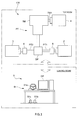
Fig. 1 is a schematic diagram showing a configuration of a vehicle drive system testing apparatus of the present embodiment; and -
Fig. 2 is a diagram showing a functional configuration of a control device of the same embodiment. - The following describes one embodiment of a vehicle drive system testing apparatus according to the present invention with reference to the accompanying drawings.
- A vehicle drive
system testing apparatus 100 of the present embodiment is intended to perform a test of a power train (also referred to as "drive line") such as a transmission (manual, automatic or CVT), differential gear, axle and a drive shaft. - Here, a vehicle drive test includes: a gear change / gear synchro test; a shift calibration of an automatic transmission; check of main components (such as a clutch, torque converter, differential gear, power unit, damper, electronic control device, suspension and exhaust system); an endurance test / life test of a drive system and drive system components; a noise / vibration test; a performance / efficiency test; a functional test, and the like.
- Specifically, as shown in
Fig. 1 , this vehicle drivesystem testing apparatus 100 is provided with: afirst load device 2 and asecond load device 3 respectively coupled to a first output shaft PT1 and a second output shaft PT2 of the power train PT; adrive device 4 coupled to an input side of the power train PT (specifically, an input shaft TM1 of the transmission); and acontrol device 5 for controlling each of theload devices drive device 4. Note that the following describes a testing apparatus of the power train PT including an automatic transmission or CVT. The power train PT serving as a test specimen, each of theload devices drive device 4 are arranged in a test room, and thecontrol device 5 is arranged in a control room separated from the test room. - The
first load device 2 and thesecond load device 3 are intended to simulate a running resistance acting on wheels connected to each of the output shafts PT1 and PT2, and each of the first andsecond load devices first absorption dynamometer 2 andsecond absorption dynamometer 3" in distinction, hereinafter). Here, the two output shafts PT1 and PT2 are the shafts which are connected to each other via the differential gear DF, and one of the left and right wheels is to be connected to the first output shaft PT1 and the other of the left and right wheels is to be connected to the second output shaft PT2. Further, thedrive device 4 is intended to simulate a behavior of an engine and thisdrive device 4 is configured of a drive dynamometer. - The
control device 5 is intended to control thefirst absorption dynamometer 2,second absorption dynamometer 3 and drivedynamometer 4 under a predetermined condition. As shown inFig. 2 , thiscontrol device 5 is provided with: aninput part 51 for inputting an operation amount corresponding to a handle operation, an accelerator operation and a brake operation of the vehicle; areception part 52 for receiving the input from theinput part 51; acontrol part 53 for controlling each of thedynamometers 2 to 4 based on each of the operation amounts received by thereception part 52; and adisplay part 54 for displaying operation contents of the operation amounts and the like received by thereception part 52 and such as control contents of each of thedynamometers 2 to 4 controlled by thecontrol part 53 on a display DP. Note that thiscontrol device 5 implemented by a dedicated or general-purpose computer equipped with: a CPU; an internal memory; an AD converter; an input/output interface; inputting means such as a mouse, keyboard or the like; and display means such as the display DP and the like. - As shown in
Fig. 1 , theinput part 51 includes: a handle operationamount input part 51a for inputting a handle operation amount corresponding to a handle operation of the vehicle; an accelerator operationamount input part 51b for inputting an accelerator operation amount corresponding to an accelerator operation of the vehicle; and a brake operationamount input part 51c for inputting a brake operation amount corresponding to a brake operation of the vehicle. In this configuration, theinput part 51 may also include a shift lever operation input part for inputting a shift lever (select lever) operation. - The handle operation
amount input part 51a is a handle controller including a steering wheel that simulates an actual steering wheel of the vehicle and it is configured to output an output signal based on a rotation angle (steering angle) from a neutral rotation position. This handle operationamount input part 51a is placed on, for example, a desk top plate and manually operated by an operator. - The accelerator operation
amount input part 51b includes an accelerator pedal that simulates an actual accelerator pedal of the vehicle and it is configured to output an output signal based on a stepping amount of the accelerator pedal. - The brake operation
amount input part 51c includes a brake pedal that simulates an actual brake pedal of the vehicle and it is configured to output an output signal based on a stepping amount of the brake pedal. - In the present embodiment, the accelerator operation
amount input part 51b and the brake operationamount input part 51c are integrally mounted on a common base member. For example, theseparts - The
reception part 52 includes: a handle operationamount reception part 52a for receiving an output signal of an operation amount from the handle operationamount input part 51a; an accelerator operationamount reception part 52b for receiving an output signal of an operation amount from the accelerator operationamount input part 51b; and a brake operationamount reception part 52c for receiving an output signal of an operation amount from the brake operationamount input part 51c. Note that, in the case of including the shift lever (select lever), thereception part 52 includes a shift lever operation reception part for receiving an output signal indicative of an operation of the shift lever. Each of thesereception parts 52a to 52c outputs each of the received output signals to thecontrol part 53. - The
control part 53 is configured to control theabsorption dynamometers drive dynamometer 4 based on the operation amounts simultaneously inputted by at least two of the handle operationamount input part 51a, accelerator operationamount input part 51b and brake operationamount input part 51c. - Specifically, the
control part 53 inputs a control signal indicative of a torque command value or a revolution number command value to theabsorption dynamometers drive dynamometer 4 based on the operation amounts simultaneously inputted by at least two of the handle operationamount input part 51a, accelerator operationamount input part 51b and brake operationamount input part 51c. For example, thecontrol part 53 inputs a command value to thedrive dynamometer 4 based on the accelerator operation amount (stepping amount of the accelerator pedal) inputted by the accelerator operationamount input part 51b. Similarly, thecontrol part 53 inputs command values to theabsorption dynamometers amount input part 51a. - Thus, in the present embodiment, the
control part 53 sets the command values to the left andright absorption dynamometers amount input part 51a. More specifically, thecontrol part 53 inputs the command values to be inputted to the left and right twodynamometers control part 53 sets the command values to be inputted to the left andright absorption dynamometers amount input part 51a and the relationship-associated data. - As the relationship-associated data, it may be considered to associate a predetermined relationship with the command values to be inputted to the left and
right absorption dynamometers right absorption dynamometers - The operation contents such as each of the operation amounts and the like inputted by the handle operation
amount input part 51a, accelerator operationamount input part 51b, brake operationamount input part 51c and the like in this way are displayed on the display device. By displaying each of the operation contents and the like on the display device in this way, an operator can operate each of the operationamount input parts 51a to 51c so that, for example, the operation amount becomes a predetermined operation amount such that the operation amount is kept constant and the like while monitoring the operation contents displayed on the display device. - In addition, the
control part 53 can also control each of thedynamometers 2 to 4 based on load data of a predetermined running model previously stored in the internal memory or external memory of thecontrol device 5. Here, the load data of the predetermined running model is the data obtained by simulating an actual running, for example, time-series data of a running resistance acting on a tire in the actual running. Further, thecontrol part 53 can also control each of thedynamometers 2 to 4 based on specific test conditions inputted by input means such as a keyboard or a mouse by a user. - In the vehicle drive
system testing apparatus 100 configured like this, a torque meter 6 (or a revolution number meter) is attached to a coupling shaft coupled to each of the output shafts PT1 and PT2 of the power train PT or each of the output shafts PT1 and PT2 of theabsorption dynamometers - According to the vehicle drive
system testing apparatus 100 configured like this, since thecontrol part 53 controls each of thedynamometers 2 to 4 based on the operation amounts simultaneously inputted by at least two of the handle operationamount input part 51a, accelerator operationamount input part 51b and brake operationamount input part 51c, the vehicle drive system can be tested while simultaneously inputting the operation amounts corresponding to the handle operation, accelerator operation or brake operation in an actual running by the handle operationamount input part 51a, accelerator operationamount input part 51b and brake operationamount input part 51c. Thus, it is possible to make the vehicle drive system testing apparatus with good usability for a user while facilitating intuitive understanding of a relationship between a handle operation and an accelerator operation or a brake operation in an actual running and allowing to simultaneously input the plurality of operating amounts thereof. For example, the vehicle drive system (power train) can be tested while inputting a complex driving operation (driving condition) that is a combination of an operation of turning the handlebars and an operation of stepping on the brake or stepping on the accelerator and further continuously changing the driving operations thereof. - Further, since the handle operation
amount input part 51a includes the steering wheel, the accelerator operationamount input part 51b includes the accelerator pedal and the brake operationamount input part 51c includes the brake pedal, the work of largely changing each of the operation amounts is extremely easy. That is, referring to the handle operationamount input part 51a, it is possible to continuously (analogously) change from a state of turning to the right to a state of instantaneously turning to the left. Referring to the accelerator operationamount input part 51b, it is possible to continuously (analogously) perform the operation of largely stepping (kicking down) the accelerator pedal. Referring to the brake operationamount input part 51c, it is possible to continuously (analogously) perform the operation of largely stepping (suddenly braking) the brake pedal. - Note that the present invention should not be limited to the above embodiment.
- For example, in the embodiment, although the description is made as to an aspect of performing a test of the power train PT while inputting a power to the power train PT using the
drive dynamometer 4, it may be also possible to perform a test of the power train PT or a test of such as fuel efficiency of an actual engine while inputting a power to the power train PT using the actual engine. - Further, in the case where the power train PT includes a manual transmission, it may be also possible to further include a clutch operation amount input part for inputting a clutch operation amount for operating the clutch of the manual transmission.
- Further, although the load device of the embodiment uses the absorption dynamometer, the other absorption motor may be used.
- Moreover, in the embodiment, although the
load devices control part 53 sets the command values to the front and rear load devices so as to simulate a revolution number difference and/or torque difference caused by an inner wheels difference between the front wheel and the rear wheel based on the handle operation amount (steering angle of the handle) inputted by the handle operationamount input part 51a. More specifically, thecontrol part 53 inputs the command values to be inputted to the front and rear two load devices with a revolution number difference and/or torque difference therebetween based on the handle operation amount. Further, it may be also possible to respectively couple the load devices to four output shafts to which the front and rear and left and right four wheels are connected. - In addition, the handle operation amount of the present embodiment may be associated with a gradient change of a road surface on which a vehicle runs. That is, it may be configured so that the gradient is changed to a plus (ascending) side when turning the handlebar to the right and the gradient is changed to a minus (descending) side when turning the handlebar to the left. With this configuration, gradient conditions can be easily inputted by simply operating the steering wheel and also the gradient can be continuously changed.
- In addition, the present invention is not limited to the above embodiments and it is needless to say that various modifications thereof can be made in a range without departing from the spirit thereof.
-
- 100
- Vehicle drive system testing apparatus
- PT
- Vehicle drive system (power train)
- TM
- Transmission
- 2
- First load device (absorption dynamometer)
- 3
- Second load device (absorption dynamometer)
- 4
- Drive device (drive dynamometer)
- 51a
- Handle operation amount input part
- 51b
- Accelerator operation amount input part
- 51c
- Brake operation amount input part
- 52a
- Handle operation amount reception part
- 52b
- Accelerator operation amount reception part
- 52c
- Brake operation amount reception part
- 53
- Control part
Claims (5)
- A vehicle drive system testing apparatus adapted to test a vehicle drive system by connecting a load device to the vehicle drive system and applying a load to the vehicle drive system, comprising:a handle operation amount input part for inputting a handle operation amount corresponding to a handle operation of a vehicle;an accelerator operation amount input part for inputting an accelerator operation amount corresponding to an accelerator operation of the vehicle;a brake operation amount input part for inputting a brake operation amount corresponding to a brake operation of the vehicle; anda control part for controlling the load device based on the operation amounts simultaneously inputted by at least two of the handle operation amount input part, the accelerator operation amount input part and the brake operation amount input part.
- The vehicle drive system testing apparatus according to claim 1, wherein the handle operation amount input part includes a steering wheel, the accelerator operation amount input part includes an accelerator pedal and the brake operation amount input part includes a brake pedal.
- The vehicle drive system testing apparatus according to claim 1 further comprising a clutch operation amount input part for inputting a clutch operation amount corresponding to a clutch operation of the vehicle.
- The vehicle drive system testing apparatus according to claim 1, wherein a first load device is connected to a first output shaft to which one of left and right wheels or one of front and rear wheels is connected and a second load device is connected to a second output shaft to which the other of the left and right wheels or the other of the front and rear wheels is connected in the vehicle drive system, and wherein
the control part controls the first load device and the second load device based on the handle operation amount so as to simulate a revolution number difference and/or torque difference caused between the two wheels. - A vehicle drive system testing control device for use in a vehicle drive system testing apparatus adapted to test a vehicle drive system by connecting a load device to the vehicle drive system and applying a load to the vehicle drive system, comprising:a handle operation amount input part for inputting a handle operation amount corresponding to a handle operation of a vehicle;an accelerator operation amount input part for inputting an accelerator operation amount corresponding to an accelerator operation of the vehicle;a brake operation amount input part for inputting a brake operation amount corresponding to a brake operation of the vehicle; anda control part for controlling the load device based on the operation amounts simultaneously inputted by at least two of the handle operation amount input part, the accelerator operation amount input part and the brake operation amount input part.
Applications Claiming Priority (1)
| Application Number | Priority Date | Filing Date | Title |
|---|---|---|---|
| JP2013272744A JP6346437B2 (en) | 2013-12-27 | 2013-12-27 | Vehicle drive system test equipment |
Publications (2)
| Publication Number | Publication Date |
|---|---|
| EP2896951A1 true EP2896951A1 (en) | 2015-07-22 |
| EP2896951B1 EP2896951B1 (en) | 2019-03-27 |
Family
ID=52282373
Family Applications (1)
| Application Number | Title | Priority Date | Filing Date |
|---|---|---|---|
| EP14004392.8A Not-in-force EP2896951B1 (en) | 2013-12-27 | 2014-12-23 | Vehicle drive system testing apparatus |
Country Status (4)
| Country | Link |
|---|---|
| US (1) | US9841350B2 (en) |
| EP (1) | EP2896951B1 (en) |
| JP (1) | JP6346437B2 (en) |
| CN (1) | CN104748973B (en) |
Cited By (1)
| Publication number | Priority date | Publication date | Assignee | Title |
|---|---|---|---|---|
| CN108762229A (en) * | 2018-05-28 | 2018-11-06 | 湖南汽车工程职业学院 | A kind of detection adjustment method of autonomous driving vehicle throttle control system |
Families Citing this family (7)
| Publication number | Priority date | Publication date | Assignee | Title |
|---|---|---|---|---|
| JP6770309B2 (en) * | 2015-12-15 | 2020-10-14 | 株式会社堀場製作所 | Fuel cell vehicle test system |
| JP6747143B2 (en) * | 2016-07-28 | 2020-08-26 | 富士電機株式会社 | Dynamometer system |
| JP6868642B2 (en) * | 2016-12-15 | 2021-05-12 | 株式会社堀場製作所 | Vehicle performance evaluation system, information processing device for vehicle performance evaluation system, vehicle performance evaluation method, and recording medium for vehicle performance evaluation system |
| WO2018110118A1 (en) * | 2016-12-15 | 2018-06-21 | 株式会社堀場製作所 | Vehicle test system, control device for vehicle test system, control method for vehicle test system, and program for vehicle test system |
| JP6913550B2 (en) | 2017-07-14 | 2021-08-04 | 株式会社堀場製作所 | Vehicle drive system test system and vehicle drive system test method |
| CN112161801A (en) * | 2020-08-29 | 2021-01-01 | 盛瑞传动股份有限公司 | Test method and test device for automatic transmission differential assembly |
| JP7180734B1 (en) * | 2021-09-06 | 2022-11-30 | 株式会社明電舎 | Control device for dynamometer system |
Citations (4)
| Publication number | Priority date | Publication date | Assignee | Title |
|---|---|---|---|---|
| JP2005083848A (en) | 2003-09-08 | 2005-03-31 | Mitsubishi Motors Corp | Powertrain bench test equipment |
| JP2006170741A (en) | 2004-12-15 | 2006-06-29 | Meidensha Corp | Abnormality detector for motive power measurement system |
| CN201348567Y (en) * | 2008-04-29 | 2009-11-18 | 重庆长安汽车股份有限公司 | Hybrid vehicle performance test simulation operation device |
| CN203148676U (en) * | 2013-03-11 | 2013-08-21 | 河南科技大学 | Vehicle transmission system testing stand |
Family Cites Families (9)
| Publication number | Priority date | Publication date | Assignee | Title |
|---|---|---|---|---|
| US5323644A (en) * | 1992-07-06 | 1994-06-28 | Ford Motor Company | Traction control road simulator |
| JP3424458B2 (en) * | 1996-09-27 | 2003-07-07 | トヨタ自動車株式会社 | Vehicle drivability evaluation device |
| JP3463859B2 (en) * | 1998-09-18 | 2003-11-05 | 日産自動車株式会社 | Inspection method for hybrid vehicles |
| JP4082101B2 (en) * | 2002-06-18 | 2008-04-30 | トヨタ自動車株式会社 | Chassis dynamo device and vehicle test method |
| JP4546752B2 (en) * | 2004-03-24 | 2010-09-15 | 株式会社日本自動車部品総合研究所 | Vehicle running state simulation apparatus equipped with drive motor and method thereof |
| EP2246686A1 (en) * | 2009-05-01 | 2010-11-03 | Froude Hofmann Limited | Vehicle test apparatus and method |
| JP2011038929A (en) * | 2009-08-12 | 2011-02-24 | Yokogawa Electric Corp | Testing apparatus for hybrid vehicle |
| SE535471C2 (en) * | 2010-10-18 | 2012-08-21 | Method and apparatus for dynamometer testing of a motor vehicle | |
| DE202011050806U1 (en) * | 2011-07-26 | 2011-10-26 | Dspace Digital Signal Processing And Control Engineering Gmbh | Remote controlled steering tester |
-
2013
- 2013-12-27 JP JP2013272744A patent/JP6346437B2/en active Active
-
2014
- 2014-12-23 US US14/581,345 patent/US9841350B2/en not_active Expired - Fee Related
- 2014-12-23 EP EP14004392.8A patent/EP2896951B1/en not_active Not-in-force
- 2014-12-23 CN CN201410812436.0A patent/CN104748973B/en not_active Expired - Fee Related
Patent Citations (4)
| Publication number | Priority date | Publication date | Assignee | Title |
|---|---|---|---|---|
| JP2005083848A (en) | 2003-09-08 | 2005-03-31 | Mitsubishi Motors Corp | Powertrain bench test equipment |
| JP2006170741A (en) | 2004-12-15 | 2006-06-29 | Meidensha Corp | Abnormality detector for motive power measurement system |
| CN201348567Y (en) * | 2008-04-29 | 2009-11-18 | 重庆长安汽车股份有限公司 | Hybrid vehicle performance test simulation operation device |
| CN203148676U (en) * | 2013-03-11 | 2013-08-21 | 河南科技大学 | Vehicle transmission system testing stand |
Cited By (2)
| Publication number | Priority date | Publication date | Assignee | Title |
|---|---|---|---|---|
| CN108762229A (en) * | 2018-05-28 | 2018-11-06 | 湖南汽车工程职业学院 | A kind of detection adjustment method of autonomous driving vehicle throttle control system |
| CN108762229B (en) * | 2018-05-28 | 2020-10-30 | 湖南汽车工程职业学院 | Detection and debugging method for accelerator control system of automatic driving automobile |
Also Published As
| Publication number | Publication date |
|---|---|
| CN104748973B (en) | 2019-01-04 |
| JP2015127651A (en) | 2015-07-09 |
| US9841350B2 (en) | 2017-12-12 |
| JP6346437B2 (en) | 2018-06-20 |
| EP2896951B1 (en) | 2019-03-27 |
| CN104748973A (en) | 2015-07-01 |
| US20150185110A1 (en) | 2015-07-02 |
Similar Documents
| Publication | Publication Date | Title |
|---|---|---|
| EP2896951B1 (en) | Vehicle drive system testing apparatus | |
| KR101779355B1 (en) | Apparatus for Car's Drive Performance Test using Electronic type Accelerator Pedal | |
| CN101476985B (en) | Hardware-in-loop semi-physical vehicle transmission-integrated simulation experiment bench | |
| US9512916B2 (en) | Customizable drive function mode system and method | |
| JP2016001174A (en) | Vehicle test system | |
| KR20160006057A (en) | Apparatus for driving simulatation of vehicle and method thereof | |
| CN103196669B (en) | Double-clutch automatic gearbox hardware-in-loop dynamic test rack | |
| US11037381B2 (en) | Vehicle drive train test system and vehicle drive train test method | |
| CN103884511B (en) | Full server automobile air outlet force measuring machine | |
| JP7103951B2 (en) | Vehicle test system, control device for vehicle test system, vehicle test system control method, and program for vehicle test system | |
| EP3705867B1 (en) | Specimen test apparatus | |
| CN116381367A (en) | Automobile dynamic electric performance test system and test method | |
| CN201364241Y (en) | Hardware-in-the-loop semi-physical automobile drive-brake comprehensive simulation experiment table | |
| CN109656235B (en) | Vehicle controller-in-the-loop simulation test system and its control method | |
| JP2021043070A (en) | Mode driving auxiliary system for vehicle | |
| KR100882258B1 (en) | Vehicle display device and display method thereof | |
| CN205706662U (en) | A kind of sensor-based driver behavior modeling system | |
| KR101265773B1 (en) | Pto load simulating apparatus for a working vehicle | |
| EP4729916A1 (en) | Test specimen testing system, test specimen driving system, test specimen testing method, and test specimen testing program | |
| Zhou et al. | Data acquisition system based on LabVIEW for ABS dynamic simulation test stand | |
| CN206609624U (en) | A kind of automobile electric power-assisted steering testing stand auxiliary route sense control system | |
| CN203561880U (en) | Detection system of automobile AMT system main control panel | |
| CN114677871B (en) | Method and device for controlling simulated engine speed | |
| CN104635716A (en) | Detecting system of master control board of automobile AMT (advanced manufacturing technology) system | |
| CN209542106U (en) | Detection controller of limited-slip differential performance test bench with road condition simulation |
Legal Events
| Date | Code | Title | Description |
|---|---|---|---|
| PUAI | Public reference made under article 153(3) epc to a published international application that has entered the european phase |
Free format text: ORIGINAL CODE: 0009012 |
|
| 17P | Request for examination filed |
Effective date: 20141223 |
|
| AK | Designated contracting states |
Kind code of ref document: A1 Designated state(s): AL AT BE BG CH CY CZ DE DK EE ES FI FR GB GR HR HU IE IS IT LI LT LU LV MC MK MT NL NO PL PT RO RS SE SI SK SM TR |
|
| AX | Request for extension of the european patent |
Extension state: BA ME |
|
| 17P | Request for examination filed |
Effective date: 20160121 |
|
| RBV | Designated contracting states (corrected) |
Designated state(s): AL AT BE BG CH CY CZ DE DK EE ES FI FR GB GR HR HU IE IS IT LI LT LU LV MC MK MT NL NO PL PT RO RS SE SI SK SM TR |
|
| STAA | Information on the status of an ep patent application or granted ep patent |
Free format text: STATUS: EXAMINATION IS IN PROGRESS |
|
| 17Q | First examination report despatched |
Effective date: 20180315 |
|
| GRAP | Despatch of communication of intention to grant a patent |
Free format text: ORIGINAL CODE: EPIDOSNIGR1 |
|
| STAA | Information on the status of an ep patent application or granted ep patent |
Free format text: STATUS: GRANT OF PATENT IS INTENDED |
|
| INTG | Intention to grant announced |
Effective date: 20181002 |
|
| GRAS | Grant fee paid |
Free format text: ORIGINAL CODE: EPIDOSNIGR3 |
|
| GRAA | (expected) grant |
Free format text: ORIGINAL CODE: 0009210 |
|
| STAA | Information on the status of an ep patent application or granted ep patent |
Free format text: STATUS: THE PATENT HAS BEEN GRANTED |
|
| AK | Designated contracting states |
Kind code of ref document: B1 Designated state(s): AL AT BE BG CH CY CZ DE DK EE ES FI FR GB GR HR HU IE IS IT LI LT LU LV MC MK MT NL NO PL PT RO RS SE SI SK SM TR |
|
| REG | Reference to a national code |
Ref country code: GB Ref legal event code: FG4D |
|
| REG | Reference to a national code |
Ref country code: CH Ref legal event code: EP |
|
| REG | Reference to a national code |
Ref country code: AT Ref legal event code: REF Ref document number: 1113673 Country of ref document: AT Kind code of ref document: T Effective date: 20190415 |
|
| REG | Reference to a national code |
Ref country code: IE Ref legal event code: FG4D |
|
| REG | Reference to a national code |
Ref country code: DE Ref legal event code: R096 Ref document number: 602014043497 Country of ref document: DE |
|
| PG25 | Lapsed in a contracting state [announced via postgrant information from national office to epo] |
Ref country code: SE Free format text: LAPSE BECAUSE OF FAILURE TO SUBMIT A TRANSLATION OF THE DESCRIPTION OR TO PAY THE FEE WITHIN THE PRESCRIBED TIME-LIMIT Effective date: 20190327 Ref country code: LT Free format text: LAPSE BECAUSE OF FAILURE TO SUBMIT A TRANSLATION OF THE DESCRIPTION OR TO PAY THE FEE WITHIN THE PRESCRIBED TIME-LIMIT Effective date: 20190327 Ref country code: NO Free format text: LAPSE BECAUSE OF FAILURE TO SUBMIT A TRANSLATION OF THE DESCRIPTION OR TO PAY THE FEE WITHIN THE PRESCRIBED TIME-LIMIT Effective date: 20190627 Ref country code: FI Free format text: LAPSE BECAUSE OF FAILURE TO SUBMIT A TRANSLATION OF THE DESCRIPTION OR TO PAY THE FEE WITHIN THE PRESCRIBED TIME-LIMIT Effective date: 20190327 |
|
| REG | Reference to a national code |
Ref country code: NL Ref legal event code: MP Effective date: 20190327 |
|
| PG25 | Lapsed in a contracting state [announced via postgrant information from national office to epo] |
Ref country code: BG Free format text: LAPSE BECAUSE OF FAILURE TO SUBMIT A TRANSLATION OF THE DESCRIPTION OR TO PAY THE FEE WITHIN THE PRESCRIBED TIME-LIMIT Effective date: 20190627 Ref country code: RS Free format text: LAPSE BECAUSE OF FAILURE TO SUBMIT A TRANSLATION OF THE DESCRIPTION OR TO PAY THE FEE WITHIN THE PRESCRIBED TIME-LIMIT Effective date: 20190327 Ref country code: LV Free format text: LAPSE BECAUSE OF FAILURE TO SUBMIT A TRANSLATION OF THE DESCRIPTION OR TO PAY THE FEE WITHIN THE PRESCRIBED TIME-LIMIT Effective date: 20190327 Ref country code: NL Free format text: LAPSE BECAUSE OF FAILURE TO SUBMIT A TRANSLATION OF THE DESCRIPTION OR TO PAY THE FEE WITHIN THE PRESCRIBED TIME-LIMIT Effective date: 20190327 Ref country code: GR Free format text: LAPSE BECAUSE OF FAILURE TO SUBMIT A TRANSLATION OF THE DESCRIPTION OR TO PAY THE FEE WITHIN THE PRESCRIBED TIME-LIMIT Effective date: 20190628 Ref country code: HR Free format text: LAPSE BECAUSE OF FAILURE TO SUBMIT A TRANSLATION OF THE DESCRIPTION OR TO PAY THE FEE WITHIN THE PRESCRIBED TIME-LIMIT Effective date: 20190327 |
|
| REG | Reference to a national code |
Ref country code: AT Ref legal event code: MK05 Ref document number: 1113673 Country of ref document: AT Kind code of ref document: T Effective date: 20190327 |
|
| PG25 | Lapsed in a contracting state [announced via postgrant information from national office to epo] |
Ref country code: IT Free format text: LAPSE BECAUSE OF FAILURE TO SUBMIT A TRANSLATION OF THE DESCRIPTION OR TO PAY THE FEE WITHIN THE PRESCRIBED TIME-LIMIT Effective date: 20190327 Ref country code: SK Free format text: LAPSE BECAUSE OF FAILURE TO SUBMIT A TRANSLATION OF THE DESCRIPTION OR TO PAY THE FEE WITHIN THE PRESCRIBED TIME-LIMIT Effective date: 20190327 Ref country code: PT Free format text: LAPSE BECAUSE OF FAILURE TO SUBMIT A TRANSLATION OF THE DESCRIPTION OR TO PAY THE FEE WITHIN THE PRESCRIBED TIME-LIMIT Effective date: 20190727 Ref country code: AL Free format text: LAPSE BECAUSE OF FAILURE TO SUBMIT A TRANSLATION OF THE DESCRIPTION OR TO PAY THE FEE WITHIN THE PRESCRIBED TIME-LIMIT Effective date: 20190327 Ref country code: EE Free format text: LAPSE BECAUSE OF FAILURE TO SUBMIT A TRANSLATION OF THE DESCRIPTION OR TO PAY THE FEE WITHIN THE PRESCRIBED TIME-LIMIT Effective date: 20190327 Ref country code: ES Free format text: LAPSE BECAUSE OF FAILURE TO SUBMIT A TRANSLATION OF THE DESCRIPTION OR TO PAY THE FEE WITHIN THE PRESCRIBED TIME-LIMIT Effective date: 20190327 Ref country code: CZ Free format text: LAPSE BECAUSE OF FAILURE TO SUBMIT A TRANSLATION OF THE DESCRIPTION OR TO PAY THE FEE WITHIN THE PRESCRIBED TIME-LIMIT Effective date: 20190327 Ref country code: RO Free format text: LAPSE BECAUSE OF FAILURE TO SUBMIT A TRANSLATION OF THE DESCRIPTION OR TO PAY THE FEE WITHIN THE PRESCRIBED TIME-LIMIT Effective date: 20190327 |
|
| PG25 | Lapsed in a contracting state [announced via postgrant information from national office to epo] |
Ref country code: SM Free format text: LAPSE BECAUSE OF FAILURE TO SUBMIT A TRANSLATION OF THE DESCRIPTION OR TO PAY THE FEE WITHIN THE PRESCRIBED TIME-LIMIT Effective date: 20190327 Ref country code: PL Free format text: LAPSE BECAUSE OF FAILURE TO SUBMIT A TRANSLATION OF THE DESCRIPTION OR TO PAY THE FEE WITHIN THE PRESCRIBED TIME-LIMIT Effective date: 20190327 |
|
| PG25 | Lapsed in a contracting state [announced via postgrant information from national office to epo] |
Ref country code: IS Free format text: LAPSE BECAUSE OF FAILURE TO SUBMIT A TRANSLATION OF THE DESCRIPTION OR TO PAY THE FEE WITHIN THE PRESCRIBED TIME-LIMIT Effective date: 20190727 Ref country code: AT Free format text: LAPSE BECAUSE OF FAILURE TO SUBMIT A TRANSLATION OF THE DESCRIPTION OR TO PAY THE FEE WITHIN THE PRESCRIBED TIME-LIMIT Effective date: 20190327 |
|
| REG | Reference to a national code |
Ref country code: DE Ref legal event code: R097 Ref document number: 602014043497 Country of ref document: DE |
|
| PG25 | Lapsed in a contracting state [announced via postgrant information from national office to epo] |
Ref country code: DK Free format text: LAPSE BECAUSE OF FAILURE TO SUBMIT A TRANSLATION OF THE DESCRIPTION OR TO PAY THE FEE WITHIN THE PRESCRIBED TIME-LIMIT Effective date: 20190327 |
|
| PGFP | Annual fee paid to national office [announced via postgrant information from national office to epo] |
Ref country code: DE Payment date: 20191210 Year of fee payment: 6 |
|
| PLBE | No opposition filed within time limit |
Free format text: ORIGINAL CODE: 0009261 |
|
| STAA | Information on the status of an ep patent application or granted ep patent |
Free format text: STATUS: NO OPPOSITION FILED WITHIN TIME LIMIT |
|
| PG25 | Lapsed in a contracting state [announced via postgrant information from national office to epo] |
Ref country code: SI Free format text: LAPSE BECAUSE OF FAILURE TO SUBMIT A TRANSLATION OF THE DESCRIPTION OR TO PAY THE FEE WITHIN THE PRESCRIBED TIME-LIMIT Effective date: 20190327 |
|
| PGFP | Annual fee paid to national office [announced via postgrant information from national office to epo] |
Ref country code: FR Payment date: 20191115 Year of fee payment: 6 |
|
| 26N | No opposition filed |
Effective date: 20200103 |
|
| PG25 | Lapsed in a contracting state [announced via postgrant information from national office to epo] |
Ref country code: TR Free format text: LAPSE BECAUSE OF FAILURE TO SUBMIT A TRANSLATION OF THE DESCRIPTION OR TO PAY THE FEE WITHIN THE PRESCRIBED TIME-LIMIT Effective date: 20190327 |
|
| PGFP | Annual fee paid to national office [announced via postgrant information from national office to epo] |
Ref country code: GB Payment date: 20191219 Year of fee payment: 6 |
|
| REG | Reference to a national code |
Ref country code: CH Ref legal event code: PL |
|
| REG | Reference to a national code |
Ref country code: BE Ref legal event code: MM Effective date: 20191231 |
|
| PG25 | Lapsed in a contracting state [announced via postgrant information from national office to epo] |
Ref country code: MC Free format text: LAPSE BECAUSE OF FAILURE TO SUBMIT A TRANSLATION OF THE DESCRIPTION OR TO PAY THE FEE WITHIN THE PRESCRIBED TIME-LIMIT Effective date: 20190327 |
|
| PG25 | Lapsed in a contracting state [announced via postgrant information from national office to epo] |
Ref country code: LU Free format text: LAPSE BECAUSE OF NON-PAYMENT OF DUE FEES Effective date: 20191223 Ref country code: IE Free format text: LAPSE BECAUSE OF NON-PAYMENT OF DUE FEES Effective date: 20191223 |
|
| PG25 | Lapsed in a contracting state [announced via postgrant information from national office to epo] |
Ref country code: CH Free format text: LAPSE BECAUSE OF NON-PAYMENT OF DUE FEES Effective date: 20191231 Ref country code: LI Free format text: LAPSE BECAUSE OF NON-PAYMENT OF DUE FEES Effective date: 20191231 Ref country code: BE Free format text: LAPSE BECAUSE OF NON-PAYMENT OF DUE FEES Effective date: 20191231 |
|
| PG25 | Lapsed in a contracting state [announced via postgrant information from national office to epo] |
Ref country code: CY Free format text: LAPSE BECAUSE OF FAILURE TO SUBMIT A TRANSLATION OF THE DESCRIPTION OR TO PAY THE FEE WITHIN THE PRESCRIBED TIME-LIMIT Effective date: 20190327 |
|
| REG | Reference to a national code |
Ref country code: DE Ref legal event code: R119 Ref document number: 602014043497 Country of ref document: DE |
|
| PG25 | Lapsed in a contracting state [announced via postgrant information from national office to epo] |
Ref country code: MT Free format text: LAPSE BECAUSE OF FAILURE TO SUBMIT A TRANSLATION OF THE DESCRIPTION OR TO PAY THE FEE WITHIN THE PRESCRIBED TIME-LIMIT Effective date: 20190327 Ref country code: HU Free format text: LAPSE BECAUSE OF FAILURE TO SUBMIT A TRANSLATION OF THE DESCRIPTION OR TO PAY THE FEE WITHIN THE PRESCRIBED TIME-LIMIT; INVALID AB INITIO Effective date: 20141223 |
|
| GBPC | Gb: european patent ceased through non-payment of renewal fee |
Effective date: 20201223 |
|
| PG25 | Lapsed in a contracting state [announced via postgrant information from national office to epo] |
Ref country code: FR Free format text: LAPSE BECAUSE OF NON-PAYMENT OF DUE FEES Effective date: 20201231 |
|
| PG25 | Lapsed in a contracting state [announced via postgrant information from national office to epo] |
Ref country code: DE Free format text: LAPSE BECAUSE OF NON-PAYMENT OF DUE FEES Effective date: 20210701 Ref country code: GB Free format text: LAPSE BECAUSE OF NON-PAYMENT OF DUE FEES Effective date: 20201223 |
|
| PG25 | Lapsed in a contracting state [announced via postgrant information from national office to epo] |
Ref country code: MK Free format text: LAPSE BECAUSE OF FAILURE TO SUBMIT A TRANSLATION OF THE DESCRIPTION OR TO PAY THE FEE WITHIN THE PRESCRIBED TIME-LIMIT Effective date: 20190327 |