EP2896838A1 - Coupling between a centrifugal fan and the suction inlet thereof - Google Patents
Coupling between a centrifugal fan and the suction inlet thereof Download PDFInfo
- Publication number
- EP2896838A1 EP2896838A1 EP13836478.1A EP13836478A EP2896838A1 EP 2896838 A1 EP2896838 A1 EP 2896838A1 EP 13836478 A EP13836478 A EP 13836478A EP 2896838 A1 EP2896838 A1 EP 2896838A1
- Authority
- EP
- European Patent Office
- Prior art keywords
- suction inlet
- centrifugal fan
- coupling
- flanges
- flow
- Prior art date
- Legal status (The legal status is an assumption and is not a legal conclusion. Google has not performed a legal analysis and makes no representation as to the accuracy of the status listed.)
- Withdrawn
Links
- 230000008878 coupling Effects 0.000 title claims abstract description 47
- 238000010168 coupling process Methods 0.000 title claims abstract description 47
- 238000005859 coupling reaction Methods 0.000 title claims abstract description 47
- 239000012530 fluid Substances 0.000 claims abstract description 19
- 239000000463 material Substances 0.000 claims description 5
- 239000000945 filler Substances 0.000 claims description 4
- 230000000694 effects Effects 0.000 description 4
- 230000002093 peripheral effect Effects 0.000 description 4
- 230000007547 defect Effects 0.000 description 1
- 229920001296 polysiloxane Polymers 0.000 description 1
- 238000007789 sealing Methods 0.000 description 1
Images


Classifications
-
- F—MECHANICAL ENGINEERING; LIGHTING; HEATING; WEAPONS; BLASTING
- F04—POSITIVE - DISPLACEMENT MACHINES FOR LIQUIDS; PUMPS FOR LIQUIDS OR ELASTIC FLUIDS
- F04D—NON-POSITIVE-DISPLACEMENT PUMPS
- F04D29/00—Details, component parts, or accessories
- F04D29/08—Sealings
- F04D29/16—Sealings between pressure and suction sides
- F04D29/161—Sealings between pressure and suction sides especially adapted for elastic fluid pumps
- F04D29/162—Sealings between pressure and suction sides especially adapted for elastic fluid pumps of a centrifugal flow wheel
-
- F—MECHANICAL ENGINEERING; LIGHTING; HEATING; WEAPONS; BLASTING
- F04—POSITIVE - DISPLACEMENT MACHINES FOR LIQUIDS; PUMPS FOR LIQUIDS OR ELASTIC FLUIDS
- F04D—NON-POSITIVE-DISPLACEMENT PUMPS
- F04D17/00—Radial-flow pumps, e.g. centrifugal pumps; Helico-centrifugal pumps
- F04D17/08—Centrifugal pumps
- F04D17/10—Centrifugal pumps for compressing or evacuating
-
- F—MECHANICAL ENGINEERING; LIGHTING; HEATING; WEAPONS; BLASTING
- F04—POSITIVE - DISPLACEMENT MACHINES FOR LIQUIDS; PUMPS FOR LIQUIDS OR ELASTIC FLUIDS
- F04D—NON-POSITIVE-DISPLACEMENT PUMPS
- F04D29/00—Details, component parts, or accessories
- F04D29/40—Casings; Connections of working fluid
- F04D29/42—Casings; Connections of working fluid for radial or helico-centrifugal pumps
- F04D29/4206—Casings; Connections of working fluid for radial or helico-centrifugal pumps especially adapted for elastic fluid pumps
- F04D29/4213—Casings; Connections of working fluid for radial or helico-centrifugal pumps especially adapted for elastic fluid pumps suction ports
-
- F—MECHANICAL ENGINEERING; LIGHTING; HEATING; WEAPONS; BLASTING
- F04—POSITIVE - DISPLACEMENT MACHINES FOR LIQUIDS; PUMPS FOR LIQUIDS OR ELASTIC FLUIDS
- F04D—NON-POSITIVE-DISPLACEMENT PUMPS
- F04D29/00—Details, component parts, or accessories
- F04D29/60—Mounting; Assembling; Disassembling
- F04D29/62—Mounting; Assembling; Disassembling of radial or helico-centrifugal pumps
- F04D29/624—Mounting; Assembling; Disassembling of radial or helico-centrifugal pumps especially adapted for elastic fluid pumps
- F04D29/626—Mounting or removal of fans
Definitions
- the present invention relates to driving gaseous fluids for applications of any type, proposing a coupling between a centrifugal fan and a suction inlet with a closure "sealing" in said coupling conferring advantageous features with respect to the current state of the art.
- a type of apparatus commonly used for driving gaseous fluids in domestic, industrial or commercial applications are those formed by a centrifugal fan with backward-curved blades connected to a suction inlet.
- the centrifugal fan defines a peripheral outlet, forming a coupling with an axial suction inlet, such that when the centrifugal fan rotates, the blades thereof suction the gaseous fluid to be driven through the suction inlet, expelling it through the peripheral outlet.
- the suction inlet is fixed and the centrifugal fan is rotary, such that between said suction inlet and the centrifugal fan a coupling which allows rotation of the centrifugal fan must be formed; said coupling must, however, have play to prevent friction.
- That play of the coupling between the centrifugal fan and the fixed suction inlet causes the ingress of a flow of disturbing fluid through said coupling because the action of the centrifugal fan inside the assembly causes negative pressure, which results in disturbance of the main suction flow, causing a distortion thereof, while at the same time producing more noise in the apparatus due to turbulences of the fluid circulating therethrough.
- the solution conventionally adopted for reducing those problems is to minimize the play of the coupling between the centrifugal fan and the suction inlet, but this has a limitation due to variations in diameters and roundness and concentricity defects between parts, so the play cannot be less than a specific value.
- the purpose of the invention is to reduce the flow of disturbing fluid in the mentioned apparatus, defining to that end the coupling between the centrifugal fan and the suction inlet in the form of a labyrinth, such that it is harder for the flow of disturbing fluid to pass through the coupling, significantly reducing the flow thereof.
- said coupling between the centrifugal fan and the suction inlet is defined by fitting together concentric flanges of both parts, play being generated between said concentric flanges forming the coupling, preventing friction therebetween, but the fitting arrangement forms a path between flanges that obstructs the passage of the flow of disturbing fluid.
- the coupling between the centrifugal fan and the suction inlet can define two or more concentric flanges of each of the parts being fitted together, whereby a labyrinthine path that obstructs the passage of disturbing flow through the coupling to a greater extent is formed, said obstruction of passage of the disturbing flow increasing the greater the number of concentric flanges forming the fitting of the coupling.
- said coupling object of the invention has very advantageous features for the suction performance of the apparatus of application, this coupling acquiring its own identity and preferred character with respect to conventional solutions in apparatus of the same type.
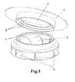
- the present invention relates to a coupling between a suction inlet (1) defining an opening (2) and a centrifugal fan (3) defining peripheral openings (4), such that in the functional arrangement, the suction inlet (1) is fixed, the centrifugal fan (3) being rotatably mounted with respect to said suction inlet (1), such that rotation of the centrifugal fan (3) causes suction of a flow of fluid (A) through the opening (2) of the suction inlet (1), to expel it through the peripheral openings (4).
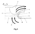
- a coupling is formed around the mentioned opening (2) between the centrifugal fan (3) and the suction inlet (1) by means of respective concentric flanges (5 and 6) of both parts, said coupling having the function of defining a closure to prevent the ingress of disturbing flow (B) therethrough, since said disturbing flow (B) causes turbulence (C) in the interior which produces loss of the effect of the sought action of suctioning the flow of fluid (A) through the opening (2) of the suction inlet (1).
- the centrifugal fan (3) must have freedom of rotation for its function, so there must be play preventing friction between the concentric flanges (5 and 6) forming the coupling around the central opening (2) between said centrifugal fan (3) and the suction inlet (1), which results in a passage between said flanges (5 and 6) of the coupling through which ingress of disturbing flow (B) causing turbulence (C) in the interior occurs, as seen in Figure 3 .
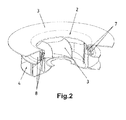
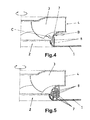
- the coupling around the opening (2) is formed by fitting together flanges (7) of the centrifugal fan (3) and flanges (8) of the suction inlet (1), as depicted in Figure 2 , whereby there is a labyrinthine passage between said flanges (7 and 8) that obstructs the ingress of disturbing flow (B) through the coupling, and therefore reduces turbulence (C) in the interior, as seen in Figure 4 .
- the labyrinthine passage for obstructing the ingress of disturbing flow (B) can be defined by fitting together a flange (7) of the centrifugal fan (3) and two flanges (8) of the suction inlet (1), like in the embodiments of Figures 4 and 7 , or conversely, like the embodiment of Figure 6 ; but the greater the number of flanges (7) and flanges (8) that are fit together, the more effective the obstruction of passage of the disturbing flow (B) through the coupling defined around the opening (2), and therefore the lower the loss of performance for suctioning the flow of fluid (A) through the suction inlet (1).
- flanges (7) of the centrifugal fan (3) and flanges (8) of the suction inlet (1) can furthermore be fitted together in the axial direction of suction, like the mentioned examples of Figures 5 to 9 ; but they can also be fitted together in the radial direction, like the examples of Figures 10 and 11 , which are also non-limiting, the concept of the invention remaining unaltered as regards defining a labyrinthine passage that obstructs the ingress of disturbing flow (B) through the coupling defined around the opening (2) of the suction inlet (1).
- the inclusion of a filler in the labyrinthine passage of the coupling with a soft moldable material, such as gel, silicone, etc. is envisaged, whereby achieving a closure that prevents almost entirely the passage of air or any other gaseous fluid through the coupling.
- the filler material does not obstruct the rotational movement of the centrifugal fan (3), because since it is a soft moldable material, when said centrifugal fan (3) rotates, it will make a channel in said filler material that allows free rotation with virtually no friction.
Landscapes
- Engineering & Computer Science (AREA)
- Mechanical Engineering (AREA)
- General Engineering & Computer Science (AREA)
- Structures Of Non-Positive Displacement Pumps (AREA)
- Nozzles For Electric Vacuum Cleaners (AREA)
Abstract
Description
- The present invention relates to driving gaseous fluids for applications of any type, proposing a coupling between a centrifugal fan and a suction inlet with a closure "sealing" in said coupling conferring advantageous features with respect to the current state of the art.
- A type of apparatus commonly used for driving gaseous fluids in domestic, industrial or commercial applications are those formed by a centrifugal fan with backward-curved blades connected to a suction inlet.
- In said apparatus, the centrifugal fan defines a peripheral outlet, forming a coupling with an axial suction inlet, such that when the centrifugal fan rotates, the blades thereof suction the gaseous fluid to be driven through the suction inlet, expelling it through the peripheral outlet.
- In the functional arrangement of said apparatus, the suction inlet is fixed and the centrifugal fan is rotary, such that between said suction inlet and the centrifugal fan a coupling which allows rotation of the centrifugal fan must be formed; said coupling must, however, have play to prevent friction.
- That play of the coupling between the centrifugal fan and the fixed suction inlet causes the ingress of a flow of disturbing fluid through said coupling because the action of the centrifugal fan inside the assembly causes negative pressure, which results in disturbance of the main suction flow, causing a distortion thereof, while at the same time producing more noise in the apparatus due to turbulences of the fluid circulating therethrough.
- The solution conventionally adopted for reducing those problems is to minimize the play of the coupling between the centrifugal fan and the suction inlet, but this has a limitation due to variations in diameters and roundness and concentricity defects between parts, so the play cannot be less than a specific value.
- The purpose of the invention is to reduce the flow of disturbing fluid in the mentioned apparatus, defining to that end the coupling between the centrifugal fan and the suction inlet in the form of a labyrinth, such that it is harder for the flow of disturbing fluid to pass through the coupling, significantly reducing the flow thereof.
- To that end, said coupling between the centrifugal fan and the suction inlet is defined by fitting together concentric flanges of both parts, play being generated between said concentric flanges forming the coupling, preventing friction therebetween, but the fitting arrangement forms a path between flanges that obstructs the passage of the flow of disturbing fluid.
- Loss of the suction effect produced by the action of the centrifugal fan in relation to the suction inlet is therefore reduced, as the centrifugal fan is not affected by the braking effect in relation to the suction inlet, such that actuation of the rotational operation of said centrifugal fan is used more effectively for the suction effect that is sought through the suction inlet, the functional performance of said suction therefore being greater.
- In that sense, the coupling between the centrifugal fan and the suction inlet can define two or more concentric flanges of each of the parts being fitted together, whereby a labyrinthine path that obstructs the passage of disturbing flow through the coupling to a greater extent is formed, said obstruction of passage of the disturbing flow increasing the greater the number of concentric flanges forming the fitting of the coupling.
- As a result, said coupling object of the invention has very advantageous features for the suction performance of the apparatus of application, this coupling acquiring its own identity and preferred character with respect to conventional solutions in apparatus of the same type.
-
-
Figure 1 shows a perspective view of an assembly of a centrifugal fan and a suction inlet that are coupled according to the invention, the centrifugal fan and suction inlet being depicted separated, in a position facing one another. -
Figure 2 shows a perspective view of the assembly of the preceding figure coupled to one another with a section that allows seeing the coupling between the centrifugal fan and suction inlet. -
Figure 3 is an enlarged partial detail of an assembly of a centrifugal fan and suction inlet connected to one another by means of a conventional coupling, depicting the main flow of fluid entering through the suction inlet and the disturbing flow entering through the coupling between the centrifugal fan and the suction inlet. -
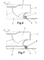
Figures 4 to 9 show different embodiments of the coupling between a centrifugal fan and a suction inlet according to the invention, fitting together concentric flanges that are axially oriented in the direction of suction. -
Figures 10 and 11 show other embodiments of the coupling between a centrifugal fan and a suction inlet according to the invention, fitting together flanges that are radially oriented with respect to the direction of suction. - The present invention relates to a coupling between a suction inlet (1) defining an opening (2) and a centrifugal fan (3) defining peripheral openings (4), such that in the functional arrangement, the suction inlet (1) is fixed, the centrifugal fan (3) being rotatably mounted with respect to said suction inlet (1), such that rotation of the centrifugal fan (3) causes suction of a flow of fluid (A) through the opening (2) of the suction inlet (1), to expel it through the peripheral openings (4).
- To favor that suction of the flow of fluid (A) through the opening (2), a coupling is formed around the mentioned opening (2) between the centrifugal fan (3) and the suction inlet (1) by means of respective concentric flanges (5 and 6) of both parts, said coupling having the function of defining a closure to prevent the ingress of disturbing flow (B) therethrough, since said disturbing flow (B) causes turbulence (C) in the interior which produces loss of the effect of the sought action of suctioning the flow of fluid (A) through the opening (2) of the suction inlet (1).
- Nevertheless, the centrifugal fan (3) must have freedom of rotation for its function, so there must be play preventing friction between the concentric flanges (5 and 6) forming the coupling around the central opening (2) between said centrifugal fan (3) and the suction inlet (1), which results in a passage between said flanges (5 and 6) of the coupling through which ingress of disturbing flow (B) causing turbulence (C) in the interior occurs, as seen in
Figure 3 . - To reduce that ingress of disturbing flow (B), the coupling around the opening (2) is formed by fitting together flanges (7) of the centrifugal fan (3) and flanges (8) of the suction inlet (1), as depicted in
Figure 2 , whereby there is a labyrinthine passage between said flanges (7 and 8) that obstructs the ingress of disturbing flow (B) through the coupling, and therefore reduces turbulence (C) in the interior, as seen inFigure 4 . - In a simple embodiment, the labyrinthine passage for obstructing the ingress of disturbing flow (B) can be defined by fitting together a flange (7) of the centrifugal fan (3) and two flanges (8) of the suction inlet (1), like in the embodiments of
Figures 4 and7 , or conversely, like the embodiment ofFigure 6 ; but the greater the number of flanges (7) and flanges (8) that are fit together, the more effective the obstruction of passage of the disturbing flow (B) through the coupling defined around the opening (2), and therefore the lower the loss of performance for suctioning the flow of fluid (A) through the suction inlet (1). - According to the foregoing, embodiments of different forms in which flanges (7) of the centrifugal fan (3) are fitted together with flanges (8) of the suction inlet (1), such as the embodiments of
Figures 5 ,8 and 9 , which are only non-limiting, representative examples. - For that purpose, flanges (7) of the centrifugal fan (3) and flanges (8) of the suction inlet (1) can furthermore be fitted together in the axial direction of suction, like the mentioned examples of
Figures 5 to 9 ; but they can also be fitted together in the radial direction, like the examples ofFigures 10 and 11 , which are also non-limiting, the concept of the invention remaining unaltered as regards defining a labyrinthine passage that obstructs the ingress of disturbing flow (B) through the coupling defined around the opening (2) of the suction inlet (1). - To achieve a more effective closure in the sense of preventing the ingress of disturbing flow (B) through the coupling between the centrifugal fan (3) and the suction inlet (1), the inclusion of a filler in the labyrinthine passage of the coupling with a soft moldable material, such as gel, silicone, etc., is envisaged, whereby achieving a closure that prevents almost entirely the passage of air or any other gaseous fluid through the coupling. In this case, the filler material does not obstruct the rotational movement of the centrifugal fan (3), because since it is a soft moldable material, when said centrifugal fan (3) rotates, it will make a channel in said filler material that allows free rotation with virtually no friction.
Claims (4)
- A coupling between a centrifugal fan and the suction inlet thereof, comprising a suction inlet (1) defining an opening (2) for the passage of a flow of fluid (A) and a centrifugal fan (3) rotatably mounted with respect to said suction inlet (1) for driving the flow of fluid (A), a closure coupling being formed around the opening (2), between the centrifugal fan (3) and the suction inlet (1), by means of respective concentric flanges between which there is play for freedom of rotation of the centrifugal fan (3), characterized in that the closure coupling around the opening (2) fits together flanges (7) of the centrifugal fan (3) and flanges (8) of the suction inlet (1), which flanges define therebetween a labyrinthine passage that obstructs the ingress of disturbing flow (B) through the coupling.
- The coupling between a centrifugal fan and the suction inlet thereof according to claim 1, characterized in that the closure coupling around the opening (2) is defined by means of flanges (7) of the centrifugal fan (3) and flanges (8) of the suction inlet (1), fitting them together in the axial direction of suction of the flow of fluid (A).
- The coupling between a centrifugal fan and the suction inlet thereof according to claim 1, characterized in that the closure coupling around the opening (2) is defined by means of flanges (7) of the centrifugal fan (3) and flanges (8) of the suction inlet (1), fitting them together in the radial direction of suction of the flow of fluid (A).
- The coupling between a centrifugal fan and the suction inlet thereof according to claim 1, characterized in that a filler with a soft moldable material is included in the labyrinthine passage defining the fitting together of flanges (7) of the centrifugal fan (3) and flanges (8) of the suction inlet (1).
Applications Claiming Priority (2)
| Application Number | Priority Date | Filing Date | Title |
|---|---|---|---|
| ES201231407A ES2455065B1 (en) | 2012-09-12 | 2012-09-12 | COUPLING BETWEEN A CENTRIFUGAL RODETE AND ITS SUCTION MOUTH |
| PCT/ES2013/070525 WO2014041223A1 (en) | 2012-09-12 | 2013-07-18 | Coupling between a centrifugal fan and the suction inlet thereof |
Publications (2)
| Publication Number | Publication Date |
|---|---|
| EP2896838A1 true EP2896838A1 (en) | 2015-07-22 |
| EP2896838A4 EP2896838A4 (en) | 2016-06-29 |
Family
ID=50277672
Family Applications (1)
| Application Number | Title | Priority Date | Filing Date |
|---|---|---|---|
| EP13836478.1A Withdrawn EP2896838A4 (en) | 2012-09-12 | 2013-07-18 | Coupling between a centrifugal fan and the suction inlet thereof |
Country Status (4)
| Country | Link |
|---|---|
| US (1) | US20150211541A1 (en) |
| EP (1) | EP2896838A4 (en) |
| ES (1) | ES2455065B1 (en) |
| WO (1) | WO2014041223A1 (en) |
Cited By (4)
| Publication number | Priority date | Publication date | Assignee | Title |
|---|---|---|---|---|
| EP3647603A1 (en) * | 2018-10-31 | 2020-05-06 | Carrier Corporation | Arrangement of centrifugal impeller of a fan for reducing noise |
| CN113357736A (en) * | 2020-03-05 | 2021-09-07 | Lg电子株式会社 | Air purifier |
| WO2022238685A1 (en) * | 2021-05-13 | 2022-11-17 | Dyson Technology Limited | A compressor |
| US12480515B2 (en) | 2021-05-13 | 2025-11-25 | Dyson Technology Limited | Compressor |
Families Citing this family (3)
| Publication number | Priority date | Publication date | Assignee | Title |
|---|---|---|---|---|
| JP6260481B2 (en) * | 2013-10-21 | 2018-01-17 | 株式会社デンソー | Centrifugal blower |
| CN114718888A (en) * | 2021-01-04 | 2022-07-08 | 青岛海尔滚筒洗衣机有限公司 | Centrifugal fan and washing equipment with same |
| FR3124558A1 (en) * | 2021-06-24 | 2022-12-30 | Airinspace | Pavilion for fan |
Family Cites Families (12)
| Publication number | Priority date | Publication date | Assignee | Title |
|---|---|---|---|---|
| US3842902A (en) * | 1973-07-05 | 1974-10-22 | Hayes Albion Corp | Labyrinthian fan |
| JPS56118593A (en) * | 1980-02-25 | 1981-09-17 | Hitachi Ltd | Blower |
| US5489186A (en) * | 1991-08-30 | 1996-02-06 | Airflow Research And Manufacturing Corp. | Housing with recirculation control for use with banded axial-flow fans |
| DE69333845T2 (en) * | 1992-05-15 | 2006-04-27 | Siemens Vdo Automotive Inc., Chatham | Axial |
| JP3649815B2 (en) * | 1996-08-14 | 2005-05-18 | カルソニックカンセイ株式会社 | Centrifugal blower |
| US6508624B2 (en) * | 2001-05-02 | 2003-01-21 | Siemens Automotive, Inc. | Turbomachine with double-faced rotor-shroud seal structure |
| JP2004092583A (en) * | 2002-09-03 | 2004-03-25 | Japan Servo Co Ltd | Centrifugal fan |
| US7883312B2 (en) * | 2005-03-31 | 2011-02-08 | Mitsubishi Heavy Industries, Ltd. | Centrifugal blower |
| JP4865497B2 (en) * | 2006-10-19 | 2012-02-01 | 三菱重工業株式会社 | Centrifugal blower |
| US8568095B2 (en) * | 2006-12-29 | 2013-10-29 | Carrier Corporation | Reduced tip clearance losses in axial flow fans |
| US8167550B2 (en) * | 2007-12-18 | 2012-05-01 | Denso Corporation | Blower unit |
| JP5486943B2 (en) * | 2010-01-29 | 2014-05-07 | 株式会社東芝 | Electric blower |
-
2012
- 2012-09-12 ES ES201231407A patent/ES2455065B1/en active Active
-
2013
- 2013-07-18 EP EP13836478.1A patent/EP2896838A4/en not_active Withdrawn
- 2013-07-18 WO PCT/ES2013/070525 patent/WO2014041223A1/en not_active Ceased
- 2013-07-18 US US14/424,299 patent/US20150211541A1/en not_active Abandoned
Cited By (8)
| Publication number | Priority date | Publication date | Assignee | Title |
|---|---|---|---|---|
| EP3647603A1 (en) * | 2018-10-31 | 2020-05-06 | Carrier Corporation | Arrangement of centrifugal impeller of a fan for reducing noise |
| US11566634B2 (en) | 2018-10-31 | 2023-01-31 | Carrier Corporation | Arrangement of centrifugal impeller of a fan for reducing noise |
| CN113357736A (en) * | 2020-03-05 | 2021-09-07 | Lg电子株式会社 | Air purifier |
| EP3875768A1 (en) * | 2020-03-05 | 2021-09-08 | LG Electronics Inc. | Air purifier |
| WO2022238685A1 (en) * | 2021-05-13 | 2022-11-17 | Dyson Technology Limited | A compressor |
| GB2606557B (en) * | 2021-05-13 | 2024-07-24 | Dyson Technology Ltd | A compressor |
| US12480516B2 (en) | 2021-05-13 | 2025-11-25 | Dyson Technology Limited | Compressor |
| US12480515B2 (en) | 2021-05-13 | 2025-11-25 | Dyson Technology Limited | Compressor |
Also Published As
| Publication number | Publication date |
|---|---|
| US20150211541A1 (en) | 2015-07-30 |
| EP2896838A4 (en) | 2016-06-29 |
| ES2455065B1 (en) | 2014-11-04 |
| ES2455065A1 (en) | 2014-04-14 |
| WO2014041223A1 (en) | 2014-03-20 |
Similar Documents
| Publication | Publication Date | Title |
|---|---|---|
| US20150211541A1 (en) | Coupling between a centrifugal fan and the suction inlet thereof | |
| CN107061320B (en) | Electric fan and vacuum cleaner having the same | |
| JP6229141B2 (en) | Blower | |
| US11332052B2 (en) | Centrifugal blower device | |
| JP7529598B2 (en) | Blowers and ventilation fans | |
| CN104295531A (en) | Centrifugal fan and air conditioner | |
| JP6332546B2 (en) | Centrifugal blower | |
| JP5682751B2 (en) | Multi-blade blower | |
| JP6580144B2 (en) | Centrifugal blower and ventilation fan | |
| JP2010133297A (en) | Centrifugal blower | |
| JP4830519B2 (en) | Centrifugal fan | |
| KR101716356B1 (en) | Collected and discharged in a highly efficient integrated fan | |
| KR20170050309A (en) | Axial Flow Type Blower for Air Cleaner | |
| US20170175764A1 (en) | Centrifugal blower | |
| US12140155B2 (en) | Blower | |
| JP2016017500A (en) | Centrifugal blower | |
| KR20160135992A (en) | Centrifugal fan | |
| JP2004092583A (en) | Centrifugal fan | |
| JP2015102068A (en) | Centrifugal fan | |
| CN112145458A (en) | Fan and electromechanical device | |
| JP2020020286A (en) | Air conditioner | |
| JP5076324B2 (en) | Centrifugal fan | |
| JP2008180164A (en) | Electric blower and electric vacuum cleaner using it | |
| JP6089556B2 (en) | Sirocco fan | |
| JP2020063679A (en) | Centrifugal blower |
Legal Events
| Date | Code | Title | Description |
|---|---|---|---|
| PUAI | Public reference made under article 153(3) epc to a published international application that has entered the european phase |
Free format text: ORIGINAL CODE: 0009012 |
|
| 17P | Request for examination filed |
Effective date: 20150402 |
|
| AK | Designated contracting states |
Kind code of ref document: A1 Designated state(s): AL AT BE BG CH CY CZ DE DK EE ES FI FR GB GR HR HU IE IS IT LI LT LU LV MC MK MT NL NO PL PT RO RS SE SI SK SM TR |
|
| AX | Request for extension of the european patent |
Extension state: BA ME |
|
| DAX | Request for extension of the european patent (deleted) | ||
| RA4 | Supplementary search report drawn up and despatched (corrected) |
Effective date: 20160527 |
|
| RIC1 | Information provided on ipc code assigned before grant |
Ipc: F04D 29/62 20060101ALI20160520BHEP Ipc: F04D 29/16 20060101AFI20160520BHEP Ipc: F04D 29/42 20060101ALI20160520BHEP |
|
| STAA | Information on the status of an ep patent application or granted ep patent |
Free format text: STATUS: THE APPLICATION HAS BEEN WITHDRAWN |
|
| 18W | Application withdrawn |
Effective date: 20161110 |