EP2896825A1 - Renewable energy power generation device - Google Patents
Renewable energy power generation device Download PDFInfo
- Publication number
- EP2896825A1 EP2896825A1 EP12890329.1A EP12890329A EP2896825A1 EP 2896825 A1 EP2896825 A1 EP 2896825A1 EP 12890329 A EP12890329 A EP 12890329A EP 2896825 A1 EP2896825 A1 EP 2896825A1
- Authority
- EP
- European Patent Office
- Prior art keywords
- disposed
- hub
- nacelle
- power generating
- generating apparatus
- Prior art date
- Legal status (The legal status is an assumption and is not a legal conclusion. Google has not performed a legal analysis and makes no representation as to the accuracy of the status listed.)
- Granted
Links
- 238000010248 power generation Methods 0.000 title description 2
- 238000007599 discharging Methods 0.000 claims description 7
- 238000012423 maintenance Methods 0.000 description 22
- 238000004891 communication Methods 0.000 description 7
- 238000012546 transfer Methods 0.000 description 5
- 230000002093 peripheral effect Effects 0.000 description 4
- 239000000470 constituent Substances 0.000 description 3
- 238000004519 manufacturing process Methods 0.000 description 3
- 230000005540 biological transmission Effects 0.000 description 2
- 230000003247 decreasing effect Effects 0.000 description 2
- 238000010586 diagram Methods 0.000 description 2
- 238000009434 installation Methods 0.000 description 2
- 230000006835 compression Effects 0.000 description 1
- 238000007906 compression Methods 0.000 description 1
- 230000000694 effects Effects 0.000 description 1
- 230000007613 environmental effect Effects 0.000 description 1
- 239000000463 material Substances 0.000 description 1
- 238000000034 method Methods 0.000 description 1
- 238000012986 modification Methods 0.000 description 1
- 230000004048 modification Effects 0.000 description 1
Images





Classifications
-
- F—MECHANICAL ENGINEERING; LIGHTING; HEATING; WEAPONS; BLASTING
- F03—MACHINES OR ENGINES FOR LIQUIDS; WIND, SPRING, OR WEIGHT MOTORS; PRODUCING MECHANICAL POWER OR A REACTIVE PROPULSIVE THRUST, NOT OTHERWISE PROVIDED FOR
- F03D—WIND MOTORS
- F03D13/00—Assembly, mounting or commissioning of wind motors; Arrangements specially adapted for transporting wind motor components
- F03D13/20—Arrangements for mounting or supporting wind motors; Masts or towers for wind motors
-
- F—MECHANICAL ENGINEERING; LIGHTING; HEATING; WEAPONS; BLASTING
- F03—MACHINES OR ENGINES FOR LIQUIDS; WIND, SPRING, OR WEIGHT MOTORS; PRODUCING MECHANICAL POWER OR A REACTIVE PROPULSIVE THRUST, NOT OTHERWISE PROVIDED FOR
- F03D—WIND MOTORS
- F03D9/00—Adaptations of wind motors for special use; Combinations of wind motors with apparatus driven thereby; Wind motors specially adapted for installation in particular locations
- F03D9/20—Wind motors characterised by the driven apparatus
- F03D9/25—Wind motors characterised by the driven apparatus the apparatus being an electrical generator
-
- F—MECHANICAL ENGINEERING; LIGHTING; HEATING; WEAPONS; BLASTING
- F03—MACHINES OR ENGINES FOR LIQUIDS; WIND, SPRING, OR WEIGHT MOTORS; PRODUCING MECHANICAL POWER OR A REACTIVE PROPULSIVE THRUST, NOT OTHERWISE PROVIDED FOR
- F03D—WIND MOTORS
- F03D9/00—Adaptations of wind motors for special use; Combinations of wind motors with apparatus driven thereby; Wind motors specially adapted for installation in particular locations
- F03D9/20—Wind motors characterised by the driven apparatus
- F03D9/28—Wind motors characterised by the driven apparatus the apparatus being a pump or a compressor
-
- F—MECHANICAL ENGINEERING; LIGHTING; HEATING; WEAPONS; BLASTING
- F05—INDEXING SCHEMES RELATING TO ENGINES OR PUMPS IN VARIOUS SUBCLASSES OF CLASSES F01-F04
- F05B—INDEXING SCHEME RELATING TO WIND, SPRING, WEIGHT, INERTIA OR LIKE MOTORS, TO MACHINES OR ENGINES FOR LIQUIDS COVERED BY SUBCLASSES F03B, F03D AND F03G
- F05B2260/00—Function
- F05B2260/40—Transmission of power
- F05B2260/406—Transmission of power through hydraulic systems
-
- Y—GENERAL TAGGING OF NEW TECHNOLOGICAL DEVELOPMENTS; GENERAL TAGGING OF CROSS-SECTIONAL TECHNOLOGIES SPANNING OVER SEVERAL SECTIONS OF THE IPC; TECHNICAL SUBJECTS COVERED BY FORMER USPC CROSS-REFERENCE ART COLLECTIONS [XRACs] AND DIGESTS
- Y02—TECHNOLOGIES OR APPLICATIONS FOR MITIGATION OR ADAPTATION AGAINST CLIMATE CHANGE
- Y02B—CLIMATE CHANGE MITIGATION TECHNOLOGIES RELATED TO BUILDINGS, e.g. HOUSING, HOUSE APPLIANCES OR RELATED END-USER APPLICATIONS
- Y02B10/00—Integration of renewable energy sources in buildings
- Y02B10/30—Wind power
-
- Y—GENERAL TAGGING OF NEW TECHNOLOGICAL DEVELOPMENTS; GENERAL TAGGING OF CROSS-SECTIONAL TECHNOLOGIES SPANNING OVER SEVERAL SECTIONS OF THE IPC; TECHNICAL SUBJECTS COVERED BY FORMER USPC CROSS-REFERENCE ART COLLECTIONS [XRACs] AND DIGESTS
- Y02—TECHNOLOGIES OR APPLICATIONS FOR MITIGATION OR ADAPTATION AGAINST CLIMATE CHANGE
- Y02E—REDUCTION OF GREENHOUSE GAS [GHG] EMISSIONS, RELATED TO ENERGY GENERATION, TRANSMISSION OR DISTRIBUTION
- Y02E10/00—Energy generation through renewable energy sources
- Y02E10/70—Wind energy
- Y02E10/72—Wind turbines with rotation axis in wind direction
-
- Y—GENERAL TAGGING OF NEW TECHNOLOGICAL DEVELOPMENTS; GENERAL TAGGING OF CROSS-SECTIONAL TECHNOLOGIES SPANNING OVER SEVERAL SECTIONS OF THE IPC; TECHNICAL SUBJECTS COVERED BY FORMER USPC CROSS-REFERENCE ART COLLECTIONS [XRACs] AND DIGESTS
- Y02—TECHNOLOGIES OR APPLICATIONS FOR MITIGATION OR ADAPTATION AGAINST CLIMATE CHANGE
- Y02E—REDUCTION OF GREENHOUSE GAS [GHG] EMISSIONS, RELATED TO ENERGY GENERATION, TRANSMISSION OR DISTRIBUTION
- Y02E10/00—Energy generation through renewable energy sources
- Y02E10/70—Wind energy
- Y02E10/728—Onshore wind turbines
-
- Y—GENERAL TAGGING OF NEW TECHNOLOGICAL DEVELOPMENTS; GENERAL TAGGING OF CROSS-SECTIONAL TECHNOLOGIES SPANNING OVER SEVERAL SECTIONS OF THE IPC; TECHNICAL SUBJECTS COVERED BY FORMER USPC CROSS-REFERENCE ART COLLECTIONS [XRACs] AND DIGESTS
- Y02—TECHNOLOGIES OR APPLICATIONS FOR MITIGATION OR ADAPTATION AGAINST CLIMATE CHANGE
- Y02P—CLIMATE CHANGE MITIGATION TECHNOLOGIES IN THE PRODUCTION OR PROCESSING OF GOODS
- Y02P80/00—Climate change mitigation technologies for sector-wide applications
- Y02P80/10—Efficient use of energy, e.g. using compressed air or pressurized fluid as energy carrier
Definitions
- a renewable energy power generating apparatus utilizes renewable energy such as wind, tidal current, ocean current, and river current.
- renewable energy such as wind, tidal current, ocean current, and river current.
- a wind turbine power generating apparatus, a tidal current power generating apparatus, an ocean current power generating apparatus, a river current power generating apparatus, or the like can be mentioned as an example of a renewable energy power generating apparatus.
- a wind turbine power generating apparatus generally includes a rotor in which a plurality of blades is attached to a hub.
- the rotor is mounted to a nacelle disposed on a tower built on the ground or on the ocean.
- the rotor rotates upon receiving wind at the blades, so that rotation of the rotor is transmitted to a generator housed in the nacelle by a drivetrain part, the generator thereby generating electric power.
- Patent Document 1 discloses a wind turbine power generating apparatus using a hydraulic pump and a hydraulic motor as a drivetrain part.
- the hydraulic pump is driven by a hub so that pressurized oil is produced, and this pressurized oil drives the hydraulic motor.
- a generator coupled to the hydraulic motor rotation energy inputted from the hydraulic motor is converted into electric energy, and thereby electric power is generated.
- Patent Document 1 discloses a rotor shaft disposed between a hub and a hydraulic pump and supported by two bearings, the rotor shaft having an end coupled to a rotor part of the hydraulic pump.
- Patent Document 1 also discloses a shortened rotor shaft and a rotor part of the hydraulic pump fixed to the hub, the rotor part being supported by two bearings.
- Patent Documents 2 to 4 disclose a typical configuration example of a hub and a hub peripheral area of a wind turbine power generating apparatus.
- renewable energy power generating apparatuses such as a wind turbine power generating apparatus have been increased in size from the perspective of improving the power generation capacity.
- a drivetrain part of a renewable energy power generating apparatus tends to increase in size and weight to transmit large torque.
- a nacelle base plate supporting the drivetrain part has increased in size, and the increased weight of a nacelle results in an increase in the manufacture cost of a renewable energy power generating apparatus. It is desirable to develop a supporting structure for a drivetrain part, including a nacelle base plate whereby the weight of a nacelle can be reduced.
- Patent Document 1 does not disclose a support part for supporting a rotor shaft and a hydraulic pump on a nacelle base plate, in the first place. Furthermore, Patent Document 1 does not disclose or suggest a configuration for supporting a rotor shaft and a hydraulic pump on a nacelle base plate to reduce the weight of a nacelle with such a support part without interrupting maintainability of devices disposed inside the nacelle.
- Patent Documents 2 to 4 are not related to a wind turbine power generating apparatus with a drivetrain part including a hydraulic pump and a hydraulic motor.
- An object of at least one embodiment of the present invention is to provide a renewable energy power generating apparatus which has great maintainability and whereby the weight of a nacelle can be reduced.
- a renewable energy power generating apparatus includes: at least one blade; a hub to which the at least one blade is mounted; a hydraulic pump including a rotor part fixed to the hub and configured to rotate with the hub, a pressurized-oil generation mechanism configured to produce pressurized oil by rotation of the rotor part, a stator part which forms a pump interior space for accommodating the pressurized-oil generation mechanism with the rotor part, and at least one pump bearing disposed between the rotor part and the stator part; a nacelle for housing at least the hydraulic pump; a tower for supporting the nacelle; a yaw rotation bearing for rotatably supporting a nacelle base plate of the nacelle on the tower; at least one support part for supporting the stator part of the hydraulic pump on the nacelle base plate of the nacelle; at least one hydraulic motor configured to be driven by the pressurized oil produced by the pressurized-oil generation mechanism; and a generator configured to be driven by the at
- the rotor part is supported to the nacelle base plate exclusively by the at least one pump bearing so as to be rotatable.
- the at least one support part is configured to support the stator part on the nacelle base plate so that the hydraulic pump is disposed between the hub and a center axis of the yaw rotation bearing.
- the at least one support part includes an access passage for connecting a first space and a second space.
- the first space is disposed in the nacelle and accommodates the hydraulic pump.
- the second space is disposed in the nacelle and at an opposite side of the at least one support part from the first space.
- the rotor part of the hydraulic pump being supported "exclusively" by the at least one pump bearing means that the pump bearing of the hydraulic pump is the only bearing supporting the rotor part to be rotatable.
- the pump bearing does not support the rotor part "exclusively", because the rotor part of the hydraulic pump is rotatably supported not only by the pump bearing, but also by the main bearing.
- the rotor part is supported to the nacelle base plate exclusively by the at least one pump bearing so as to be rotatable.
- the shaft system of the above renewable energy power generating apparatus may be designed to be short as compared to a shaft system where the rotor part is not exclusively supported to be rotatable by the pump bearing.
- the hydraulic pump it is possible to dispose the hydraulic pump closer to the hub as compared to a case where the rotor part is not exclusively supported to be rotatable by the pump bearing, and between the hub and the center axis of the yaw rotation bearing.
- the stator part of the hydraulic pump is supported on the nacelle base plate by the at least one support part so that the hydraulic pump is disposed between the hub and the center axis of the yaw rotation bearing.
- the at least one support part includes the access passage, which makes it possible for a worker or a component to transfer between the first space and the second space in the nacelle via the access passage.
- the stator part is disposed radially inside the rotor part.
- the at least one support part is a tubular member including a bend portion which extends from the nacelle base plate toward the hub.
- the bend portion has a distal end connected to an end of the stator part which is remote from the hub.
- the tubular member includes an opening disposed on an outer side of a curved cross-sectional shape of the bend portion, the opening serving as the access passage.
- stator part is disposed radially inside the rotor part, providing a hollow part inside the stationary stator part makes it possible to arrange objects in the hollow part so that the objects arranged in the hollow part are supported on the stator part.
- the stator part includes a hollow part accommodating at least one of a device, a cable, or a pipe in the nacelle.
- the at least one hydraulic motor is disposed in the hollow part of the stator part.
- the stator part includes an inner flow channel for supplying or discharging working oil to or from the pressurized-oil generation mechanism.
- the inner flow channel extends radially inward from the pressurized-oil generation mechanism.
- An oil pipe for transferring the working oil is disposed in the hollow part and between the hydraulic pump and the at least one hydraulic motor. The oil pipe has an end connected to the inner flow channel.
- the oil pipe disposed between the hydraulic motor and the hydraulic pump is disposed in the hollow part of the stator part, which makes it possible to further reduce the size of the nacelle, and to further reduce the weight of the nacelle.
- the pressurized-oil generation mechanism includes: at least one ring cam disposed on an inner circumferential surface of the rotor part and configured to rotate with the rotor part, the at least one ring cam including a plurality of projections and recesses arranged in a circumferential direction; a plurality of cylinders disposed on a stator part side and arranged radially on an inner side of the at least one ring cam; a plurality of pistons each configured to be driven by the projections and recesses of the at least one ring cam to slide within corresponding one of the cylinders; and low pressure valves and high pressure valves for supplying and discharging working oil to and from hydraulic chambers each defined by corresponding one of the cylinders and corresponding one of the pistons disposed in the cylinder.
- the stator part is disposed radially outside the rotor part.
- the at least one support part includes a first support part and a second support part.
- the first support part is disposed on a front region of the nacelle base plate which is adjacent to the hub.
- the first support part supports an end surface of a lower part of the stator part which is adjacent to the hub.
- the second support part is disposed on a rear region of the nacelle base plate which is remote from the hub.
- the second support part supports an end surface of an upper part of the stator part which is remote from the hub.
- the moment load caused by the weight of the hub is applied to the first support part and the second support part supporting the stator part of the hydraulic pump fixed to the hub.
- supporting the stator part of the hydraulic pump with the first support part and the second support part makes it possible to support the stator part of the hydraulic pump at two supporting points, which makes it possible to support the hydraulic pump more stably.
- the stator part is disposed radially outside the rotor part.
- the at least one support part is a tubular member which includes a bend portion extending from the nacelle base plate toward the hub to reach an end surface of the stator part which is adjacent to the hub so as to surround the hydraulic pump.
- the bend portion has a distal end connected to the end surface of the stator part adjacent to the hub.
- the tubular member includes an opening disposed on an outer side of a curved cross-sectional shape of the bend portion, the opening serving as the access passage.
- the members which require maintenance and produce pressurized oil, are incorporated in the stator part disposed radially outside the rotor part.
- the support part (tubular member) is surrounding the hydraulic pump.
- the stator part is disposed radially outside the rotor part.
- the at least one support part is a tubular member which includes a bend portion extending from the nacelle base plate toward the hub to reach an end surface of the stator part which is remote from the hub.
- the bend portion has a distal end connected to the end surface of the stator part remote from the hub.
- the tubular member includes an opening disposed on an outer side of a curved cross-sectional shape of the bend portion, the opening serving as the access passage.
- the members which require maintenance and produce pressurized oil, are incorporated in the stator part disposed radially outside the rotor part.
- the distal end of the bend portion constituting a part of the support part is connected to the end surface of the stator part remote from the hub.
- the stator part of the hydraulic pump is disposed outside the support part (tubular member).
- the rotor part includes a hollow part capable of accommodating at least one of a device, a cable, or a pipe in the nacelle, the hollow part being disposed inside the rotor part.
- At least one of a device, a cable, or a pipe in the nacelle is accommodated inside the hollow part of the rotor part, which makes it possible to reduce the size of the nacelle, and to reduce the weight of the nacelle even further.
- the hollow part accommodates a slip ring for electrically connecting a stationary cable and a rotary cable which rotates with the rotor part.
- a slip ring for electrically connecting a stationary cable and a rotary cable is disposed inside the hollow part of the stator part, which makes it possible to reduce the size of the nacelle, and to reduce the weight of the nacelle even further.
- the pressurized-oil generation mechanism includes: at least one ring cam disposed on an outer circumferential surface of the rotor part and configured to rotate with the rotor part, the at least one ring cam including a plurality of projections and recesses arranged in a circumferential direction; a plurality of cylinders disposed on a stator part side and arranged radially on an outer side of the at least one ring cam; a plurality of pistons each configured to be driven by the projections and recesses of the at least one ring cam to slide within respective one of the cylinders; and low pressure valves and high pressure valves for supplying and discharging working oil to and from hydraulic chambers each defined by corresponding one of the cylinders and corresponding one of the pistons disposed in the cylinder.
- the support part includes a cast formed integrally with the nacelle base plate. In this way, it is possible to reduce the manufacture cost of the support part.
- the renewable energy power generating apparatus is a wind turbine power generating apparatus which generates electric power in the generator by utilizing wind energy received by the at least one blade from wind serving as a renewable energy source.
- a renewable energy power generating apparatus Described below is a renewable energy power generating apparatus according to one embodiment. While a wind turbine power generating apparatus is described herein as an example of a renewable energy power generating apparatus, the shaft-system assembly method according to embodiments of the present invention may be applied to other renewable energy power generating apparatuses such as a tidal current power generating apparatus, an ocean current power generating apparatus, and a river current power generating apparatus.
- FIG. 1 is a schematic diagram of an overall configuration of a wind turbine power generating apparatus 2 according to one embodiment of the present invention.
- the wind turbine power generating apparatus 2 includes at least one blade 4, a hub 6 to which the at least one blade 4 is attached, a nacelle 10, and a tower 12 for supporting the nacelle 10.
- the wind turbine power generating apparatus 2 includes a hydraulic pump 8 driven by the hub 6, a hydraulic motor 14, oil piping 15 disposed between the hydraulic pump 8 and the hydraulic motor 14, and a generator 16 connected to a rotation shaft 14A of the hydraulic motor 14 and driven by the hydraulic motor 14.
- the oil piping 15 includes a high pressure oil pipe 15A and a low pressure oil pipe 15B.
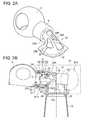
- FIG. 2A is a perspective view of a configuration example of the hub 6, the hydraulic pump 8, and a support part 30 of the wind turbine power generating apparatus 2 according to one embodiment.
- FIG. 2B is a cross-sectional view of the hub 6, the hydraulic pump 8, and the support part 30 of the wind turbine power generating apparatus 2 taken from FIG. 2A .
- the wind turbine power generating apparatus 2 further includes a yaw rotation bearing 28 for rotatably supporting a nacelle base plate 10A of the nacelle 10 on the tower 12, and at least one support part 30 for supporting a stator part 22 of the hydraulic pump 8, which will be described below, on the nacelle base plate 10A of the nacelle 10.
- the at least one support part 30 supports the stator part 22 on the nacelle base plate 10A so that the hydraulic pump 8 is disposed between the hub 6 and the center axis O of the yaw rotation bearing 28.
- the nacelle base plate 10A is a member supporting a drivetrain part including the hydraulic pump 8 and other devices in the nacelle 10.
- the nacelle base plate 10A is connected to the tower 12 via the yaw rotation bearing 28.
- the support part 30 includes an access passage 32 (32A, 32B) connecting the first space SP1 and the second space SP2.
- the first space SP1 is in the nacelle 10 and accommodates the hydraulic pump 8, while the second space SP2 is in the nacelle 10 and disposed on the opposite side of the support part 30 from the first space SP1. In this way, it is possible for a worker to access the first space SP1 via the access passage 32 (32A, 32B) from the second space SP2 in the nacelle 10 to perform maintenance on the hydraulic pump 8.
- the support part 30 may be disposed integrally with the nacelle base plate 10A.
- the support part 30 and the nacelle base plate 10A may be a cast formed as one piece.
- the access passage 32 (32A, 32B) is disposed so as to connect the first space SP1 in the nacelle 10 and the second space SP2 in the nacelle 10.
- the access passage 32 includes an opening 32A disposed on a part of the support part 30 that faces the second space SP2, and openings 32B disposed on lateral sides of the support part 30 (opposite sides of a vertical plane including a rotational center axis of the hydraulic pump 8).
- the access passage 32 includes only the opening 32A disposed on a part of the support part 30 that faces the second space SP2. In this case, it is possible to reduce the opening area on the support part 30 and improve rigidity of the support part 30, without interrupting smooth transfer of a worker between the first space SP1 and the second space SP2.
- the access passage 32 includes only the openings 32B disposed on the lateral sides of the support part 30. In this case, no opening is disposed on a part that greatly affects the rigidity of the support part 30 against a moment load caused by the weight of the blade 4 and the hub 6, (which is a part of the support part 30 that faces the second space SP2). Thus, it is possible to improve rigidity of the support part 30.
- the hydraulic pump 8 includes a rotor part 18 fixed to the hub 6 so as to rotate with the hub 6, a pressurized-oil generation mechanism 20 configured to produce pressurized oil from rotation of the rotor part 18, and the stator part 22 forming a pump interior space that accommodates the pressurized-oil generation mechanism 20 with the rotor part 18.
- the hydraulic pump 8 also includes at least one pump bearing 24 disposed between the rotor part 18 and the stator part 22.
- the rotor part 18 of the hydraulic pump 8 is supported to the nacelle base plate 10A so as to be rotatable, exclusively by the at least one pump bearing 24.
- the at least pump bearing 24 is the only bearing supporting the rotor part 18 rotatably.
- the rotor part 18 is supported to the nacelle base plate 10A exclusively by a pair of pump bearings 24.
- alignment operation is normally required for matching the axial centers of the respective bearings.
- alignment is normally carried out for a pair of main bearings during installation of a shaft system onto a nacelle base plate.
- the stator part 22 is disposed radially inside the rotor part 18.
- the at least one support part 30 is a tubular member 36 that includes a bend portion 30D extending from the nacelle base plate 10A toward the hub 6.
- the bend portion 30D which constitutes a part of the support part 30, has a distal end connected to an end of the stator part 22 that is remote from the hub 6.
- the support part 30 (tubular member 36) includes the opening 32A serving as the access passage 32 disposed on the outer side of the curved cross-sectional shape (see FIG. 2B ) of the bend portion 30D. That is, the opening 32A is disposed on a part of the support part 30 that faces the second space SP2.
- stator part 22 is disposed radially inside the rotor part 18, providing a hollow part 22A inside the stationary stator part 22 makes it possible to arrange objects in the hollow part 22A so that the arranged objects are supported on the stator part 22.
- the hollow part 22A inside the stationary stator part 22 accommodates at least one of a device, a cable, or a pipe in the nacelle 10. In another embodiment, the hollow part 22A inside the stator part 22 accommodates the hydraulic motor 14, which is one of the devices in the nacelle 10.
- the stator part 22 includes an internal flow channel 40 for supplying or discharging working oil to or from the pressurized-oil generation mechanism 20.
- the internal flow channel 40 extends from the pressurized-oil generation mechanism 20 radially inward.
- the hollow part 22A includes at least one length of the oil piping 15 (at least one of the high pressure oil pipe 15A or the low pressure oil pipe 15B) disposed between the hydraulic pump 8 and the at least one hydraulic motor 14 and connected to the internal flow channel 40 at one end.
- FIG. 2B only illustrates one pipe as the oil piping 15, the oil piping 15 may include two pipes that form the high pressure oil pipe 15A and the low pressure oil pipe 15B, respectively.
- the oil piping 15 including the at least one pipe disposed between the hydraulic motor 14 and the hydraulic pump 8 is disposed inside the hollow part 22A of the stator part 22, which makes it possible to reduce the size of the nacelle 10 even further, and to further reduce the weight of the nacelle 10.
- FIG. 3 is a cross-sectional view of a hydraulic pump 8 and its peripheral area taken in the radial direction of the hydraulic pump 8 of the wind turbine power generating apparatus 2 in FIG. 2 .
- the pressurized-oil generation mechanism 20 includes at least one ring cam 45, a plurality of cylinders 44, a plurality of pistons 46, low pressure valves 50, and high pressure valves 52.
- the at least one ring cam 45 includes a plurality of projections and recesses arranged in the circumferential direction (i.e. lobe).
- the ring cam 45 is disposed on the inner circumferential surface of the rotor part 18 so as to rotate with the rotor part 18.
- the plurality of cylinders 44 are disposed on the stator part 22 side and arranged radially on the inner side of the at least one ring cam 45.
- each cylinder 44 is disposed in the radial direction of the ring cam 45, the center axis of each cylinder is slightly inclined from the radial direction in some embodiments.
- the plurality of pistons 46 is driven by the projections and recesses of the at least one ring cam 45 and slides inside the respective cylinders 44.
- Each piston 46 includes a piston body 46A and a roller 46B.
- the low pressure valves 50 and the high pressure valves 52 each have a supply function and a discharge function, respectively, of working oil to and from a hydraulic chamber 48 defined by the corresponding cylinder 44 and the corresponding piston 46 disposed inside the cylinder 44.
- the hydraulic chambers 48 are connected to the high pressure oil pipe 15A via respective high pressure communication channels 56, and to the low pressure oil pipe 15B via respective low pressure communication channels 54.
- the plurality of projections and recesses (lobe) of the ring cam 45 presses the rollers 46B of the pistons 46, so that the piston bodies 46A repeatedly reciprocate in the axial direction of the cylinders 44.
- the volume of each hydraulic chamber 48 formed by the corresponding piston body 46A and cylinder 44 is cyclically varied.
- the volume of each hydraulic chamber 48 is reduced, the working oil in the hydraulic chamber 48 is compressed so that the compressed working oil is turned into high pressure oil and discharged to the high pressure oil pipe (compression stroke).
- the volume of each hydraulic chamber 48 is increased, the working oil is suctioned into the hydraulic chamber 48 (intake stroke).
- the high pressure oil is supplied to the hydraulic motor 14 via the high pressure oil pipe 15A.
- the hydraulic motor 14 is driven by the hydraulic pressure of the high pressure oil so that the rotation shaft 14A of the hydraulic motor 14 rotates. Rotation of the rotation shaft 14A of the hydraulic motor 14 transmits to the rotation shaft of the generator 16, and the rotation shaft of the generator 16 rotates.
- the generator 16 converts kinetic energy of its rotation shaft into electric energy, thereby generating electric power.
- the high pressure oil After performing work for the hydraulic motor 14, the high pressure oil has its pressure decreased and turns into low pressure oil.
- the low pressure oil is supplied to the hydraulic pump 8 from the hydraulic motor 14 via the low pressure oil pipe 15B.
- the low pressure oil supplied to the hydraulic pump 8 has it pressure increased again by the hydraulic pump 8 and turns into high pressure oil to be supplied again to the hydraulic motor 14.
- FIG. 4A is a perspective view of a configuration example of the hub 6, the hydraulic pump 8, and the support part 30 of the wind turbine power generating apparatus 2 according to one embodiment.
- FIG. 4B is a cross-sectional view of the hub 6, the hydraulic pump 8, and the support part 30 of the wind turbine power generating apparatus 2 taken from FIG. 4A .
- the stator part 22 is disposed radially outside the rotor part 18.
- the at least one support part 30 includes the first support part 30A and the second support part 30B.
- the first support part 30A is disposed on a front region of the nacelle base plate 10A that is adjacent to the hub 6, so as to support an end surface of the lower part of the stator part 22 that is adjacent to the hub 6.
- the second support part 30B includes an opening 32A serving as the access passage 32.
- the second support part 30B is disposed on a rear region of the nacelle base plate 10A that is remote from the hub 6, so as to support an end surface of the upper part of the stator part 22 that is remote from the hub 6.
- the support part 30 supports the stator part 22 of the hydraulic pump 8 on the nacelle base plate 10A so that the hydraulic pump 8 is disposed between the hub 6 and the center axis O of the yaw rotation bearing 28.
- the rotor part 18 is supported so as to be rotatable on the nacelle base plate 10A side exclusively by the pump bearings 24.
- first support part 30A and the second support part 30B no support part is disposed on the lateral sides of the hydraulic pump 8.
- a pair of passage spaces 32B is disposed on the opposite sides of the hydraulic pump 8, serving as the access passage 32. In this way, it is possible for a worker to move between the first space SP1 and the second space SP2 via the passage spaces 32B.
- the pair of passage spaces 32B alone is disposed as the access passage 32. In this case, it is possible to improve the rigidity of the second support part 30B while maintaining accessibility between the first space SP1 and the second space SP2 with the passage spaces 32B.
- the moment load caused by the weight of the hub 6 is applied to the first support part 30A and the second support part 30B supporting the stator part 22 of the hydraulic pump 8 fixed to the hub 6.
- supporting the stator part 22 of the hydraulic pump 8 with the first support part 30A and the second support part 30B makes it possible to support the stator part 22 of the hydraulic pump 8 at two supporting points, which makes it possible to support the hydraulic pump 8 more stably.
- first end plate 38A and second end plate 38B is disposed on the opposite ends of the stator part 22 so as to cover the outer circumferential surface of the pressurized-oil generation mechanism 20.
- the first end plate 38A adjacent to the hub 6 and the second end plate 38B remote from the hub 6 are each supported on the outer circumference of the rotor part 18 via corresponding one of the pump bearings 24.
- the first end plate 38A includes the internal flow channel 40 through which the high pressure oil produced in the hydraulic chambers 48 flows toward the high pressure oil pipe 15A.
- the internal flow channel 40 communicates with the hydraulic chambers 48 via the high pressure communication channels 56.
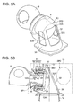
- FIG. 5A is a perspective view of a configuration example of the hub 6, the hydraulic pump 8, and the support part 30 of the wind turbine power generating apparatus 2 according to one embodiment.
- FIG. 5B is a cross-sectional view of the hub 6, the hydraulic pump 8, and the support part 30 of the wind turbine power generating apparatus 2 taken from FIG. 5A .
- the stator part 22 is disposed radially outside of the rotor part 18.
- the at least one support part 30 is a tubular member 36 including a bend portion 30D that extends from the nacelle base plate 10A toward the hub 6 to reach an end surface of the stator part 22 that is adjacent to the hub 6 so as to surround the hydraulic pump 8.
- the support part 30 supports the stator part 22 of the hydraulic pump 8 on the nacelle base plate 10A so that the hydraulic pump 8 is disposed between the hub 6 and the center axis O of the yaw rotation bearing 28.
- the rotor part 18 is supported so as to be rotatable on the nacelle base plate 10A side exclusively by the pump bearings 24.
- the bend portion 30D constituting a part of the support part 30 has a distal end connected to an end surface of the stator part 22 that is adjacent to the hub 6, and the support part 30 (tubular member 36) includes an opening 32A serving as the access passage 32 disposed on the outer side of the curved cross-sectional shape of the bend portion 30D.
- the lateral portions of the support part 30, which are portions on the opposite sides of the vertical plane including the rotational center axis of the hydraulic pump 8, also include a pair of openings 32A that serves as the access passage 32.
- the access passage 32 includes only the opening 32A disposed on a part of the support part 30 that faces the second space SP2. In this case, it is possible to reduce the opening area on the support part 30 to improve rigidity of the support part 30, without interrupting smooth transfer of a worker between the first space SP1 and the second space SP2.
- the access passage 32 includes only the openings 32B disposed on the lateral sides of the support part 30. In this case, no opening is disposed on a part that greatly affects rigidity of the support part 30 against a moment load caused by the weight of the blade 4 and the hub 6, which is a part of the support part 30 facing the second space SP2. Thus, it is possible to improve rigidity of the support part 30.
- the constituent members for producing pressurized oil such as valves like the low pressure valves 50 and the high pressure valves 52 and members including a sliding part like the pistons 46 and the cylinders 44.
- Such constituent members are normally incorporated in the stator part 22 of the hydraulic pump 8.
- the stator part 22 is disposed radially outside of the rotor part 18, and the support part 30 (tubular member 36) is surrounding the hydraulic pump 8.
- the support part 30 tubular member 36
- FIG. 6A is a perspective view of a configuration example of the hub 6, the hydraulic pump 8, and the support part 30 of the wind turbine power generating apparatus 2 according to one embodiment.
- FIG. 6B is a cross-sectional view of the hub 6, the hydraulic pump 8, and the support part 30 of the wind turbine power generating apparatus 2 taken from FIG. 6A .
- the stator part 22 is disposed radially outside the rotor part 18.
- the at least one support part 30 is a tubular member 36 including a bend portion 30D that extends from the nacelle base plate 10A toward the hub 6 to reach an end surface of the stator part 22 that is remote from the hub 6.
- the support part 30 supports the stator part 22 of the hydraulic pump 8 on the nacelle base plate 10A so that the hydraulic pump 8 is disposed between the hub 6 and the center axis O of the yaw rotation bearing 28.
- the rotor part 18 is supported so as to be rotatable on the nacelle base plate 10A exclusively by the pump bearings 24.
- the bend portion 30D constituting a part of the support part 30 has a distal end connected to an end surface of the stator part 22 that is remote from the hub 6, and the support part 30 (tubular member 36) includes an opening 32A serving as the access passage 32 disposed on the outer side of the curved cross-sectional shape of the bend portion 30D.
- the lateral portions of the support part 30, which are portions on the opposite sides of the vertical plane including the rotational center axis of the hydraulic pump 8, also include a pair of openings 32A that serves as the access passage 32.
- the access passage 32 includes only the opening 32A disposed on a part of the support part 30 that faces the second space SP2. In this case, it is possible to reduce the opening area on the support part 30 to improve rigidity of the support part 30, without interrupting smooth transfer of a worker between the first space SP1 and the second space SP2.
- the access passage 32 includes only the openings 32B disposed on the lateral sides of the support part 30. In this case, no opening is disposed on a part that greatly affects rigidity of the support part 30 against a moment load caused by the weight of the blade 4 and the hub 6, which is a part of the support part 30 that faces the second space SP2. Thus, it is possible to improve rigidity of the support part 30.
- the hydraulic pump 8 Since the distal end of the bend portion 30D constituting a part of the support part 30 is connected to the end surface of the stator part 22 of the hydraulic pump 8 remote from the hub 6, the hydraulic pump 8 is disposed outside of the support part 30 (tubular member 36). As a result, it is possible to complete maintenance of the hydraulic pump 8 outside the support part 30 (tubular member 36), depending on the contents of the maintenance work (see FIG. 6A ).
- devices for controlling operation of the wind turbine power generating apparatus 2, which require maintenance are disposed inside the support part 30 (tubular member 36).
- a maintenance worker to enter the support part 30 (tubular member 36) via the access passage 32 disposed on the support part 30 (tubular member 36) to perform maintenance on the above devices.
- the rotor part 18 includes a hollow part 18A inside, and the hollow part 18A may accommodate at least one of a device, a cable or a pipe in the nacelle 10. Further, the hollow part 18A of the rotor part 18 may accommodate a slip ring (not illustrated) for electrically connecting the stationary cables and the rotary cables rotating with the rotor part 18.
- FIG. 7 is a cross-sectional view of a hydraulic pump 8 and its peripheral area along the radial direction of the hydraulic pump 8 of the wind turbine power generating apparatus 2 taken from FIG. 6 .
- the pressurized-oil generation mechanism 20 includes at least one ring cam 45, a plurality of cylinders 44, a plurality of pistons 46, low pressure valves 50 and high pressure valves 52.
- the at least one ring cam 45 includes a plurality of projections and recesses arranged in the circumferential direction (i.e. lobe).
- the ring cam 45 is disposed on the outer circumferential surface of the rotor part 18 so as to rotate with the rotor part 18.
- the plurality of cylinders 44 are disposed on the stator part 22 side and arranged radially on the outer side of the at least one ring cam 45.
- the plurality of pistons 46 is driven by the projections and recesses of the at least one ring cam 45 and slides inside the respective cylinders 44.
- Each piston 46 includes a piston body 46A and a roller 46B.
- the low pressure valves 50 and the high pressure valves 52 each have a supply function and a discharge function, respectively, of working oil to and from a hydraulic chamber 48 defined by the corresponding cylinder 44 and the corresponding piston 46 disposed inside the cylinder 44.
- the hydraulic chambers 48 are connected to the high pressure oil pipe 15A via respective high pressure communication channels 56, and to the low pressure oil pipe 15B via respective low pressure communication channels 54.
- the blade 4 When the blade 4 receives wind, the blade 4 rotates.
- the rotor part 18 of the hydraulic pump 8 mounted to the hub 6 rotates, and thereby rotation of the rotor part 18 rotates the ring cam 45 mounted to the outer circumferential surface of the rotor part 18.
- each hydraulic chamber 48 Due to the reciprocating motion of the piston bodies 46A, the volume of each hydraulic chamber 48 is cyclically varied. When the volume of each hydraulic chamber 48 is reduced, the working oil in the hydraulic chamber 48 is compressed so that the compressed working oil turns into high pressure oil to be discharged to the high pressure oil pipe 15A. When the volume of each hydraulic chamber 48 is increased, the working oil is suctioned into the hydraulic chamber 48.
- the high pressure oil is supplied to the hydraulic motor 14 via the high pressure oil pipe 15A.
- the hydraulic motor 14 is driven by the hydraulic pressure of the high pressure oil so that the rotation shaft 14A of the hydraulic motor 14 rotates. Rotation of the rotation shaft 14A of the hydraulic motor 14 transmits to the rotation shaft (not illustrated) of the generator 16, and the rotation shaft of the generator 16 rotates.
- the generator 16 converts the kinetic energy of its rotation shaft into electric energy, thereby generating electric power.
- the high pressure oil After performing work for the hydraulic motor 14, the high pressure oil has its pressure decreased and turns into low pressure oil.
- the low pressure oil is supplied to the hydraulic pump 8 from the hydraulic motor 14 via the low pressure oil pipe 15B.
- the low pressure oil supplied to the hydraulic pump 8 has its pressure increased again by the hydraulic pump 8 and turns into high pressure oil to be supplied again to the hydraulic motor 14.
- the at least one pump bearing exclusively supports the rotor part 18 of the hydraulic pump 8 so as to be rotatable on the nacelle base plate 10A side.
- the shaft system of the above renewable energy power generating apparatus may be designed to be short as compared to a shaft system where the rotor part 18 is not exclusively supported to be rotatable by the pump bearing 24.
- the stator part 22 of the hydraulic pump 8 is supported on the nacelle base plate 10A by the at least one support part 30 so that the hydraulic pump 8 is disposed between the hub 6 and the center axis O of the yaw rotation bearing 28.
- the at least one support part 30 includes the access passage 32, which makes it possible for a worker or a component to transfer between the first space and the second space in the nacelle 10 via the access passage 32.
Landscapes
- Engineering & Computer Science (AREA)
- Life Sciences & Earth Sciences (AREA)
- Sustainable Development (AREA)
- Sustainable Energy (AREA)
- Chemical & Material Sciences (AREA)
- Combustion & Propulsion (AREA)
- Mechanical Engineering (AREA)
- General Engineering & Computer Science (AREA)
- Power Engineering (AREA)
- Wind Motors (AREA)
Abstract

Description
- The present disclosure relates to renewable energy power generating apparatuses. A renewable energy power generating apparatus utilizes renewable energy such as wind, tidal current, ocean current, and river current. A wind turbine power generating apparatus, a tidal current power generating apparatus, an ocean current power generating apparatus, a river current power generating apparatus, or the like can be mentioned as an example of a renewable energy power generating apparatus.
- In view of the increasing environmental awareness, a wind turbine power generating apparatus has drawn attention in recent years as a renewable energy power generating apparatus. A wind turbine power generating apparatus generally includes a rotor in which a plurality of blades is attached to a hub. The rotor is mounted to a nacelle disposed on a tower built on the ground or on the ocean. In a wind turbine power generating apparatus of this type, the rotor rotates upon receiving wind at the blades, so that rotation of the rotor is transmitted to a generator housed in the nacelle by a drivetrain part, the generator thereby generating electric power.
-
Patent Document 1 discloses a wind turbine power generating apparatus using a hydraulic pump and a hydraulic motor as a drivetrain part. In this wind turbine power generating apparatus, the hydraulic pump is driven by a hub so that pressurized oil is produced, and this pressurized oil drives the hydraulic motor. Then, in a generator coupled to the hydraulic motor, rotation energy inputted from the hydraulic motor is converted into electric energy, and thereby electric power is generated. Further, as a specific example of a shaft system of the drivetrain part,Patent Document 1 discloses a rotor shaft disposed between a hub and a hydraulic pump and supported by two bearings, the rotor shaft having an end coupled to a rotor part of the hydraulic pump.Patent Document 1 also discloses a shortened rotor shaft and a rotor part of the hydraulic pump fixed to the hub, the rotor part being supported by two bearings. - Although not related to a wind turbine power generating apparatus including a hydraulic pump and a hydraulic motor as a drivetrain part,
Patent Documents 2 to 4 disclose a typical configuration example of a hub and a hub peripheral area of a wind turbine power generating apparatus. -
- Patent Document 1:
US Patent Application Pub. No. 2010/0032959 - Patent Document 2:
DE 102008063874A - Patent Document 3: Japanese Patent Unexamined Application Pub. No.
2005-337267 - Patent Document 4: Japanese Patent Unexamined Application Pub. No.
2009-162380 - Meanwhile, renewable energy power generating apparatuses such as a wind turbine power generating apparatus have been increased in size from the perspective of improving the power generation capacity. Thus, a drivetrain part of a renewable energy power generating apparatus tends to increase in size and weight to transmit large torque. As a result, a nacelle base plate supporting the drivetrain part has increased in size, and the increased weight of a nacelle results in an increase in the manufacture cost of a renewable energy power generating apparatus. It is desirable to develop a supporting structure for a drivetrain part, including a nacelle base plate whereby the weight of a nacelle can be reduced.
- In this regard,
Patent Document 1 does not disclose a support part for supporting a rotor shaft and a hydraulic pump on a nacelle base plate, in the first place. Furthermore,Patent Document 1 does not disclose or suggest a configuration for supporting a rotor shaft and a hydraulic pump on a nacelle base plate to reduce the weight of a nacelle with such a support part without interrupting maintainability of devices disposed inside the nacelle. - Further, in the first place,
Patent Documents 2 to 4 are not related to a wind turbine power generating apparatus with a drivetrain part including a hydraulic pump and a hydraulic motor. - An object of at least one embodiment of the present invention is to provide a renewable energy power generating apparatus which has great maintainability and whereby the weight of a nacelle can be reduced.
- A renewable energy power generating apparatus according to at least one embodiment of the present invention includes: at least one blade; a hub to which the at least one blade is mounted; a hydraulic pump including a rotor part fixed to the hub and configured to rotate with the hub, a pressurized-oil generation mechanism configured to produce pressurized oil by rotation of the rotor part, a stator part which forms a pump interior space for accommodating the pressurized-oil generation mechanism with the rotor part, and at least one pump bearing disposed between the rotor part and the stator part; a nacelle for housing at least the hydraulic pump; a tower for supporting the nacelle; a yaw rotation bearing for rotatably supporting a nacelle base plate of the nacelle on the tower; at least one support part for supporting the stator part of the hydraulic pump on the nacelle base plate of the nacelle; at least one hydraulic motor configured to be driven by the pressurized oil produced by the pressurized-oil generation mechanism; and a generator configured to be driven by the at least one hydraulic motor. The rotor part is supported to the nacelle base plate exclusively by the at least one pump bearing so as to be rotatable. The at least one support part is configured to support the stator part on the nacelle base plate so that the hydraulic pump is disposed between the hub and a center axis of the yaw rotation bearing. The at least one support part includes an access passage for connecting a first space and a second space. The first space is disposed in the nacelle and accommodates the hydraulic pump. The second space is disposed in the nacelle and at an opposite side of the at least one support part from the first space.
- In the present specification, the rotor part of the hydraulic pump being supported "exclusively" by the at least one pump bearing means that the pump bearing of the hydraulic pump is the only bearing supporting the rotor part to be rotatable. For example, in a case where the rotor part of the hydraulic pump is connected to a main shaft that is supported on a nacelle base plate via a main bearing to rotate with a hub, the pump bearing does not support the rotor part "exclusively", because the rotor part of the hydraulic pump is rotatably supported not only by the pump bearing, but also by the main bearing.
- In the above renewable energy power generating apparatus, the rotor part is supported to the nacelle base plate exclusively by the at least one pump bearing so as to be rotatable. Thus, it is possible to shorten the shaft system for power transmission from the hub to the hydraulic pump. Specifically, the shaft system of the above renewable energy power generating apparatus may be designed to be short as compared to a shaft system where the rotor part is not exclusively supported to be rotatable by the pump bearing. As a result, it is possible to dispose the hydraulic pump closer to the hub as compared to a case where the rotor part is not exclusively supported to be rotatable by the pump bearing, and between the hub and the center axis of the yaw rotation bearing. Such layout of the hydraulic pump contributes to considerable reduction in the size and weight of the nacelle that accommodates the hydraulic pump. Thus, in order to achieve the above layout of the hydraulic pump, in the above renewable energy power generating apparatus, the stator part of the hydraulic pump is supported on the nacelle base plate by the at least one support part so that the hydraulic pump is disposed between the hub and the center axis of the yaw rotation bearing. Here, the at least one support part includes the access passage, which makes it possible for a worker or a component to transfer between the first space and the second space in the nacelle via the access passage. Thus, it is possible to reduce the weight of the nacelle while ensuring maintainability.
- In some embodiments, the stator part is disposed radially inside the rotor part. The at least one support part is a tubular member including a bend portion which extends from the nacelle base plate toward the hub. The bend portion has a distal end connected to an end of the stator part which is remote from the hub. The tubular member includes an opening disposed on an outer side of a curved cross-sectional shape of the bend portion, the opening serving as the access passage.
- In this way, with the opening serving as the access passage disposed on the outer side of the curved cross-sectional shape of the bend portion, it is possible for a maintenance worker to move in and out of the support part (tubular member) via the access passage more easily, which makes it possible to perform maintenance on the hydraulic pump efficiently. Thus, the maintainability of the hydraulic pump is improved.
- Further, since the stator part is disposed radially inside the rotor part, providing a hollow part inside the stationary stator part makes it possible to arrange objects in the hollow part so that the objects arranged in the hollow part are supported on the stator part.
- In some embodiments, the stator part includes a hollow part accommodating at least one of a device, a cable, or a pipe in the nacelle. In some embodiments, the at least one hydraulic motor is disposed in the hollow part of the stator part.
- In one embodiment, the stator part includes an inner flow channel for supplying or discharging working oil to or from the pressurized-oil generation mechanism. The inner flow channel extends radially inward from the pressurized-oil generation mechanism. An oil pipe for transferring the working oil is disposed in the hollow part and between the hydraulic pump and the at least one hydraulic motor. The oil pipe has an end connected to the inner flow channel.
- As described above, the oil pipe disposed between the hydraulic motor and the hydraulic pump is disposed in the hollow part of the stator part, which makes it possible to further reduce the size of the nacelle, and to further reduce the weight of the nacelle.
- In some embodiments, the pressurized-oil generation mechanism includes: at least one ring cam disposed on an inner circumferential surface of the rotor part and configured to rotate with the rotor part, the at least one ring cam including a plurality of projections and recesses arranged in a circumferential direction; a plurality of cylinders disposed on a stator part side and arranged radially on an inner side of the at least one ring cam; a plurality of pistons each configured to be driven by the projections and recesses of the at least one ring cam to slide within corresponding one of the cylinders; and low pressure valves and high pressure valves for supplying and discharging working oil to and from hydraulic chambers each defined by corresponding one of the cylinders and corresponding one of the pistons disposed in the cylinder.
- In some embodiments, the stator part is disposed radially outside the rotor part. The at least one support part includes a first support part and a second support part. The first support part is disposed on a front region of the nacelle base plate which is adjacent to the hub. The first support part supports an end surface of a lower part of the stator part which is adjacent to the hub. The second support part is disposed on a rear region of the nacelle base plate which is remote from the hub. The second support part supports an end surface of an upper part of the stator part which is remote from the hub.
- The moment load caused by the weight of the hub is applied to the first support part and the second support part supporting the stator part of the hydraulic pump fixed to the hub. Here, supporting the stator part of the hydraulic pump with the first support part and the second support part makes it possible to support the stator part of the hydraulic pump at two supporting points, which makes it possible to support the hydraulic pump more stably.
- In some embodiments, the stator part is disposed radially outside the rotor part. The at least one support part is a tubular member which includes a bend portion extending from the nacelle base plate toward the hub to reach an end surface of the stator part which is adjacent to the hub so as to surround the hydraulic pump. The bend portion has a distal end connected to the end surface of the stator part adjacent to the hub. The tubular member includes an opening disposed on an outer side of a curved cross-sectional shape of the bend portion, the opening serving as the access passage.
- The members, which require maintenance and produce pressurized oil, are incorporated in the stator part disposed radially outside the rotor part. On the other hand, the support part (tubular member) is surrounding the hydraulic pump. Thus, it is possible to access and perform maintenance on the stator part disposed radially outside of the rotor part from a space between the support part (tubular member) and the hydraulic pump. As a result, it is possible to complete maintenance of the hydraulic pump inside the support part (tubular member), depending on the contents of the maintenance work.
- In some embodiments, the stator part is disposed radially outside the rotor part. The at least one support part is a tubular member which includes a bend portion extending from the nacelle base plate toward the hub to reach an end surface of the stator part which is remote from the hub. The bend portion has a distal end connected to the end surface of the stator part remote from the hub. The tubular member includes an opening disposed on an outer side of a curved cross-sectional shape of the bend portion, the opening serving as the access passage.
- The members, which require maintenance and produce pressurized oil, are incorporated in the stator part disposed radially outside the rotor part. On the other hand, the distal end of the bend portion constituting a part of the support part is connected to the end surface of the stator part remote from the hub. Thus, the stator part of the hydraulic pump is disposed outside the support part (tubular member). As a result, it is possible to complete maintenance of the hydraulic pump outside the support part (tubular member), depending on the contents of the maintenance work.
- In some embodiments, the rotor part includes a hollow part capable of accommodating at least one of a device, a cable, or a pipe in the nacelle, the hollow part being disposed inside the rotor part.
- In this way, at least one of a device, a cable, or a pipe in the nacelle is accommodated inside the hollow part of the rotor part, which makes it possible to reduce the size of the nacelle, and to reduce the weight of the nacelle even further.
- In some embodiments, the hollow part accommodates a slip ring for electrically connecting a stationary cable and a rotary cable which rotates with the rotor part.
- In this way, a slip ring for electrically connecting a stationary cable and a rotary cable is disposed inside the hollow part of the stator part, which makes it possible to reduce the size of the nacelle, and to reduce the weight of the nacelle even further.
- In some embodiments, the pressurized-oil generation mechanism includes: at least one ring cam disposed on an outer circumferential surface of the rotor part and configured to rotate with the rotor part, the at least one ring cam including a plurality of projections and recesses arranged in a circumferential direction; a plurality of cylinders disposed on a stator part side and arranged radially on an outer side of the at least one ring cam; a plurality of pistons each configured to be driven by the projections and recesses of the at least one ring cam to slide within respective one of the cylinders; and low pressure valves and high pressure valves for supplying and discharging working oil to and from hydraulic chambers each defined by corresponding one of the cylinders and corresponding one of the pistons disposed in the cylinder.
- In some embodiments, the support part includes a cast formed integrally with the nacelle base plate. In this way, it is possible to reduce the manufacture cost of the support part.
- In some embodiments, the renewable energy power generating apparatus is a wind turbine power generating apparatus which generates electric power in the generator by utilizing wind energy received by the at least one blade from wind serving as a renewable energy source.
- According to the present invention, it is possible to provide a renewable energy power generating apparatus which has a great maintainability and whereby the weight of a nacelle can be reduced.
-
-
FIG. 1 is a schematic diagram of an overall configuration of a wind turbine power generating apparatus according to one embodiment of the present invention. -
FIGs. 2A ,4A ,5A ,6A are each a perspective view of a configuration example of a hub, a hydraulic pump, and a support part of a wind turbine power generating apparatus according to one embodiment.FIGs. 2B ,4B ,5B ,6B are each a cross-sectional view of the hub, the hydraulic pump, and the support part of the wind turbine power generating apparatus taken fromFIGs. 2A ,4A ,5A , and6A , respectively. -
FIGs. 3 and7 are each a cross-sectional view of a hydraulic pump and its peripheral area taken in the radial direction of the hydraulic pump of the wind turbine power generating apparatus inFIGs. 2 and6 , respectively. - Embodiments of the present invention will now be described in detail with reference to the accompanying drawings. It is intended, however, that unless particularly specified, dimensions, materials, shapes, relative positions and the like of components described in the embodiments shall be interpreted as illustrative only and not limitative of the scope of the present invention.
- Described below is a renewable energy power generating apparatus according to one embodiment. While a wind turbine power generating apparatus is described herein as an example of a renewable energy power generating apparatus, the shaft-system assembly method according to embodiments of the present invention may be applied to other renewable energy power generating apparatuses such as a tidal current power generating apparatus, an ocean current power generating apparatus, and a river current power generating apparatus.
-
FIG. 1 is a schematic diagram of an overall configuration of a wind turbinepower generating apparatus 2 according to one embodiment of the present invention. As illustrated in the drawing, the wind turbinepower generating apparatus 2 includes at least oneblade 4, ahub 6 to which the at least oneblade 4 is attached, anacelle 10, and atower 12 for supporting thenacelle 10. - Further, the wind turbine
power generating apparatus 2 includes ahydraulic pump 8 driven by thehub 6, ahydraulic motor 14, oil piping 15 disposed between thehydraulic pump 8 and thehydraulic motor 14, and agenerator 16 connected to arotation shaft 14A of thehydraulic motor 14 and driven by thehydraulic motor 14. Theoil piping 15 includes a highpressure oil pipe 15A and a lowpressure oil pipe 15B. -
FIG. 2A is a perspective view of a configuration example of thehub 6, thehydraulic pump 8, and asupport part 30 of the wind turbinepower generating apparatus 2 according to one embodiment.FIG. 2B is a cross-sectional view of thehub 6, thehydraulic pump 8, and thesupport part 30 of the wind turbinepower generating apparatus 2 taken fromFIG. 2A . - As illustrated in
FIG. 2B , the wind turbinepower generating apparatus 2 according to one embodiment further includes a yaw rotation bearing 28 for rotatably supporting anacelle base plate 10A of thenacelle 10 on thetower 12, and at least onesupport part 30 for supporting astator part 22 of thehydraulic pump 8, which will be described below, on thenacelle base plate 10A of thenacelle 10. - The at least one
support part 30 supports thestator part 22 on thenacelle base plate 10A so that thehydraulic pump 8 is disposed between thehub 6 and the center axis O of theyaw rotation bearing 28. Here, thenacelle base plate 10A is a member supporting a drivetrain part including thehydraulic pump 8 and other devices in thenacelle 10. Thenacelle base plate 10A is connected to thetower 12 via theyaw rotation bearing 28. - The
support part 30 includes an access passage 32 (32A, 32B) connecting the first space SP1 and the second space SP2. The first space SP1 is in thenacelle 10 and accommodates thehydraulic pump 8, while the second space SP2 is in thenacelle 10 and disposed on the opposite side of thesupport part 30 from the first space SP1. In this way, it is possible for a worker to access the first space SP1 via the access passage 32 (32A, 32B) from the second space SP2 in thenacelle 10 to perform maintenance on thehydraulic pump 8. - Here, the
support part 30 may be disposed integrally with thenacelle base plate 10A. For instance, thesupport part 30 and thenacelle base plate 10A may be a cast formed as one piece. - The access passage 32 (32A, 32B) is disposed so as to connect the first space SP1 in the
nacelle 10 and the second space SP2 in thenacelle 10. In one embodiment, as illustrated inFIGs. 2A and 2B , theaccess passage 32 includes anopening 32A disposed on a part of thesupport part 30 that faces the second space SP2, andopenings 32B disposed on lateral sides of the support part 30 (opposite sides of a vertical plane including a rotational center axis of the hydraulic pump 8). - In another embodiment, the
access passage 32 includes only theopening 32A disposed on a part of thesupport part 30 that faces the second space SP2. In this case, it is possible to reduce the opening area on thesupport part 30 and improve rigidity of thesupport part 30, without interrupting smooth transfer of a worker between the first space SP1 and the second space SP2. - In yet another embodiment, the
access passage 32 includes only theopenings 32B disposed on the lateral sides of thesupport part 30. In this case, no opening is disposed on a part that greatly affects the rigidity of thesupport part 30 against a moment load caused by the weight of theblade 4 and thehub 6, (which is a part of thesupport part 30 that faces the second space SP2). Thus, it is possible to improve rigidity of thesupport part 30. - Further, as illustrated in
FIG. 2B , thehydraulic pump 8 includes arotor part 18 fixed to thehub 6 so as to rotate with thehub 6, a pressurized-oil generation mechanism 20 configured to produce pressurized oil from rotation of therotor part 18, and thestator part 22 forming a pump interior space that accommodates the pressurized-oil generation mechanism 20 with therotor part 18. Thehydraulic pump 8 also includes at least onepump bearing 24 disposed between therotor part 18 and thestator part 22. - The
rotor part 18 of thehydraulic pump 8 is supported to thenacelle base plate 10A so as to be rotatable, exclusively by the at least onepump bearing 24. In other words, the at least pump bearing 24 is the only bearing supporting therotor part 18 rotatably. - In some embodiments, as illustrated in
FIG. 2B , therotor part 18 is supported to thenacelle base plate 10A exclusively by a pair ofpump bearings 24. In a case where a plurality of bearings supports a rotation shaft, alignment operation is normally required for matching the axial centers of the respective bearings. In a typical wind turbine power generating apparatus where a pair of main bearings supports a main shaft rotating with a hub on a nacelle base plate, alignment is normally carried out for a pair of main bearings during installation of a shaft system onto a nacelle base plate. In view of this, if therotor part 18 is to be supported to thenacelle base plate 10A exclusively by the pair ofpump bearings 24 incorporated in thehydraulic pump 8, it would be possible to perform alignment on thepump bearings 24 in advance during assembly of thehydraulic pump 8 in a manufacturing plant. As a result, it is possible to dispense with alignment operation of bearings carried out at an installation site of the wind turbinepower generating apparatus 2. - As illustrated in
FIGs. 2A and 2B , in one embodiment, thestator part 22 is disposed radially inside therotor part 18. The at least onesupport part 30 is atubular member 36 that includes abend portion 30D extending from thenacelle base plate 10A toward thehub 6. Thebend portion 30D, which constitutes a part of thesupport part 30, has a distal end connected to an end of thestator part 22 that is remote from thehub 6. The support part 30 (tubular member 36) includes theopening 32A serving as theaccess passage 32 disposed on the outer side of the curved cross-sectional shape (seeFIG. 2B ) of thebend portion 30D. That is, theopening 32A is disposed on a part of thesupport part 30 that faces the second space SP2. - In this way, with the
opening 32A serving as theaccess passage 32 disposed on the outer side of the curved cross-sectional shape of thebend portion 30D, it is possible for a maintenance worker to move in and out of the support part 30 (tubular member 36) via theaccess passage 32 more easily, which makes it possible to perform maintenance on thehydraulic pump 8 efficiently. Thus, the maintainability of thehydraulic pump 8 is improved. - Further, since the
stator part 22 is disposed radially inside therotor part 18, providing ahollow part 22A inside thestationary stator part 22 makes it possible to arrange objects in thehollow part 22A so that the arranged objects are supported on thestator part 22. - In one embodiment, the
hollow part 22A inside thestationary stator part 22 accommodates at least one of a device, a cable, or a pipe in thenacelle 10. In another embodiment, thehollow part 22A inside thestator part 22 accommodates thehydraulic motor 14, which is one of the devices in thenacelle 10. - As illustrated in
FIG. 2B , in one embodiment, thestator part 22 includes aninternal flow channel 40 for supplying or discharging working oil to or from the pressurized-oil generation mechanism 20. Theinternal flow channel 40 extends from the pressurized-oil generation mechanism 20 radially inward. On the other hand, thehollow part 22A includes at least one length of the oil piping 15 (at least one of the highpressure oil pipe 15A or the lowpressure oil pipe 15B) disposed between thehydraulic pump 8 and the at least onehydraulic motor 14 and connected to theinternal flow channel 40 at one end. Here, whileFIG. 2B only illustrates one pipe as theoil piping 15, theoil piping 15 may include two pipes that form the highpressure oil pipe 15A and the lowpressure oil pipe 15B, respectively. - As described above, the oil piping 15 including the at least one pipe disposed between the
hydraulic motor 14 and thehydraulic pump 8 is disposed inside thehollow part 22A of thestator part 22, which makes it possible to reduce the size of thenacelle 10 even further, and to further reduce the weight of thenacelle 10. -
FIG. 3 is a cross-sectional view of ahydraulic pump 8 and its peripheral area taken in the radial direction of thehydraulic pump 8 of the wind turbinepower generating apparatus 2 inFIG. 2 . As illustrated in the drawing, the pressurized-oil generation mechanism 20 includes at least onering cam 45, a plurality ofcylinders 44, a plurality ofpistons 46,low pressure valves 50, andhigh pressure valves 52. - The at least one
ring cam 45 includes a plurality of projections and recesses arranged in the circumferential direction (i.e. lobe). Thering cam 45 is disposed on the inner circumferential surface of therotor part 18 so as to rotate with therotor part 18. The plurality ofcylinders 44 are disposed on thestator part 22 side and arranged radially on the inner side of the at least onering cam 45. Here, while eachcylinder 44 is disposed in the radial direction of thering cam 45, the center axis of each cylinder is slightly inclined from the radial direction in some embodiments. - The plurality of
pistons 46 is driven by the projections and recesses of the at least onering cam 45 and slides inside therespective cylinders 44. Eachpiston 46 includes apiston body 46A and aroller 46B. Thelow pressure valves 50 and thehigh pressure valves 52 each have a supply function and a discharge function, respectively, of working oil to and from ahydraulic chamber 48 defined by the correspondingcylinder 44 and thecorresponding piston 46 disposed inside thecylinder 44. In some embodiments, thehydraulic chambers 48 are connected to the highpressure oil pipe 15A via respective highpressure communication channels 56, and to the lowpressure oil pipe 15B via respective lowpressure communication channels 54. - When the
blade 4 receives wind, a lift applied to theblade 4 generates a component of moment about an X axis (torque), which has a function of rotating theblade 4. When theblade 4 rotates, thehub 6 to which theblade 4 is mounted also rotates (seeFIG. 1 ). - Due to the rotation of the
hub 6, therotor part 18 of thehydraulic pump 8 attached to thehub 6 rotates (seeFIG. 2B ). Due to the rotation of therotor part 18, thering cam 45 attached to the inner circumferential surface of therotor part 18 rotates (seeFIG. 3 ). - Then, due to the rotation of the
ring cam 45, the plurality of projections and recesses (lobe) of thering cam 45 presses therollers 46B of thepistons 46, so that thepiston bodies 46A repeatedly reciprocate in the axial direction of thecylinders 44. Due to the reciprocating motion of thepiston bodies 46A, the volume of eachhydraulic chamber 48 formed by thecorresponding piston body 46A andcylinder 44 is cyclically varied. When the volume of eachhydraulic chamber 48 is reduced, the working oil in thehydraulic chamber 48 is compressed so that the compressed working oil is turned into high pressure oil and discharged to the high pressure oil pipe (compression stroke). When the volume of eachhydraulic chamber 48 is increased, the working oil is suctioned into the hydraulic chamber 48 (intake stroke). - Once the high pressure oil is discharged into the high
pressure oil pipe 15A, the high pressure oil is supplied to thehydraulic motor 14 via the highpressure oil pipe 15A. Thehydraulic motor 14 is driven by the hydraulic pressure of the high pressure oil so that therotation shaft 14A of thehydraulic motor 14 rotates. Rotation of therotation shaft 14A of thehydraulic motor 14 transmits to the rotation shaft of thegenerator 16, and the rotation shaft of thegenerator 16 rotates. Thegenerator 16 converts kinetic energy of its rotation shaft into electric energy, thereby generating electric power. - After performing work for the
hydraulic motor 14, the high pressure oil has its pressure decreased and turns into low pressure oil. The low pressure oil is supplied to thehydraulic pump 8 from thehydraulic motor 14 via the lowpressure oil pipe 15B. The low pressure oil supplied to thehydraulic pump 8 has it pressure increased again by thehydraulic pump 8 and turns into high pressure oil to be supplied again to thehydraulic motor 14. -
FIG. 4A is a perspective view of a configuration example of thehub 6, thehydraulic pump 8, and thesupport part 30 of the wind turbinepower generating apparatus 2 according to one embodiment.FIG. 4B is a cross-sectional view of thehub 6, thehydraulic pump 8, and thesupport part 30 of the wind turbinepower generating apparatus 2 taken fromFIG. 4A . - As illustrated in
FIGs. 4A and 4B , in one embodiment, thestator part 22 is disposed radially outside therotor part 18. The at least onesupport part 30 includes thefirst support part 30A and thesecond support part 30B. Thefirst support part 30A is disposed on a front region of thenacelle base plate 10A that is adjacent to thehub 6, so as to support an end surface of the lower part of thestator part 22 that is adjacent to thehub 6. Thesecond support part 30B includes anopening 32A serving as theaccess passage 32. Thesecond support part 30B is disposed on a rear region of thenacelle base plate 10A that is remote from thehub 6, so as to support an end surface of the upper part of thestator part 22 that is remote from thehub 6. In this way, thesupport part 30 supports thestator part 22 of thehydraulic pump 8 on thenacelle base plate 10A so that thehydraulic pump 8 is disposed between thehub 6 and the center axis O of theyaw rotation bearing 28. On the other hand, therotor part 18 is supported so as to be rotatable on thenacelle base plate 10A side exclusively by thepump bearings 24. - Further, between the
first support part 30A and thesecond support part 30B, no support part is disposed on the lateral sides of thehydraulic pump 8. Thus, a pair ofpassage spaces 32B is disposed on the opposite sides of thehydraulic pump 8, serving as theaccess passage 32. In this way, it is possible for a worker to move between the first space SP1 and the second space SP2 via thepassage spaces 32B. - In another embodiment, the pair of
passage spaces 32B alone is disposed as theaccess passage 32. In this case, it is possible to improve the rigidity of thesecond support part 30B while maintaining accessibility between the first space SP1 and the second space SP2 with thepassage spaces 32B. - The moment load caused by the weight of the
hub 6 is applied to thefirst support part 30A and thesecond support part 30B supporting thestator part 22 of thehydraulic pump 8 fixed to thehub 6. Here, supporting thestator part 22 of thehydraulic pump 8 with thefirst support part 30A and thesecond support part 30B makes it possible to support thestator part 22 of thehydraulic pump 8 at two supporting points, which makes it possible to support thehydraulic pump 8 more stably. - As illustrated in the drawing, a pair of
first end plate 38A andsecond end plate 38B is disposed on the opposite ends of thestator part 22 so as to cover the outer circumferential surface of the pressurized-oil generation mechanism 20. Thefirst end plate 38A adjacent to thehub 6 and thesecond end plate 38B remote from thehub 6 are each supported on the outer circumference of therotor part 18 via corresponding one of thepump bearings 24. Thefirst end plate 38A includes theinternal flow channel 40 through which the high pressure oil produced in thehydraulic chambers 48 flows toward the highpressure oil pipe 15A. Theinternal flow channel 40 communicates with thehydraulic chambers 48 via the highpressure communication channels 56. -
FIG. 5A is a perspective view of a configuration example of thehub 6, thehydraulic pump 8, and thesupport part 30 of the wind turbinepower generating apparatus 2 according to one embodiment.FIG. 5B is a cross-sectional view of thehub 6, thehydraulic pump 8, and thesupport part 30 of the wind turbinepower generating apparatus 2 taken fromFIG. 5A . - As illustrated in
FIGs. 5A and 5B , in one embodiment, thestator part 22 is disposed radially outside of therotor part 18. The at least onesupport part 30 is atubular member 36 including abend portion 30D that extends from thenacelle base plate 10A toward thehub 6 to reach an end surface of thestator part 22 that is adjacent to thehub 6 so as to surround thehydraulic pump 8. Thesupport part 30 supports thestator part 22 of thehydraulic pump 8 on thenacelle base plate 10A so that thehydraulic pump 8 is disposed between thehub 6 and the center axis O of theyaw rotation bearing 28. On the other hand, therotor part 18 is supported so as to be rotatable on thenacelle base plate 10A side exclusively by thepump bearings 24. - The
bend portion 30D constituting a part of thesupport part 30 has a distal end connected to an end surface of thestator part 22 that is adjacent to thehub 6, and the support part 30 (tubular member 36) includes anopening 32A serving as theaccess passage 32 disposed on the outer side of the curved cross-sectional shape of thebend portion 30D. Further, the lateral portions of thesupport part 30, which are portions on the opposite sides of the vertical plane including the rotational center axis of thehydraulic pump 8, also include a pair ofopenings 32A that serves as theaccess passage 32. - In another embodiment, the
access passage 32 includes only theopening 32A disposed on a part of thesupport part 30 that faces the second space SP2. In this case, it is possible to reduce the opening area on thesupport part 30 to improve rigidity of thesupport part 30, without interrupting smooth transfer of a worker between the first space SP1 and the second space SP2. - In yet another embodiment, the
access passage 32 includes only theopenings 32B disposed on the lateral sides of thesupport part 30. In this case, no opening is disposed on a part that greatly affects rigidity of thesupport part 30 against a moment load caused by the weight of theblade 4 and thehub 6, which is a part of thesupport part 30 facing the second space SP2. Thus, it is possible to improve rigidity of thesupport part 30. - Maintenance needs to be performed on the constituent members for producing pressurized oil, such as valves like the
low pressure valves 50 and thehigh pressure valves 52 and members including a sliding part like thepistons 46 and thecylinders 44. Such constituent members are normally incorporated in thestator part 22 of thehydraulic pump 8. In the present embodiment, thestator part 22 is disposed radially outside of therotor part 18, and the support part 30 (tubular member 36) is surrounding thehydraulic pump 8. Thus, it is possible to access and perform maintenance on the constituent members requiring maintenance incorporated in thestator part 22 disposed radially outside of therotor part 18 from a space between the support part 30 (tubular member 36) and thehydraulic pump 8. As a result, it is possible to complete maintenance of thehydraulic pump 8 inside the support part 30 (tubular member 36), depending on the contents of the maintenance work. -
FIG. 6A is a perspective view of a configuration example of thehub 6, thehydraulic pump 8, and thesupport part 30 of the wind turbinepower generating apparatus 2 according to one embodiment.FIG. 6B is a cross-sectional view of thehub 6, thehydraulic pump 8, and thesupport part 30 of the wind turbinepower generating apparatus 2 taken fromFIG. 6A . - As illustrated in
FIGs. 6A and 6B , in one embodiment, thestator part 22 is disposed radially outside therotor part 18. The at least onesupport part 30 is atubular member 36 including abend portion 30D that extends from thenacelle base plate 10A toward thehub 6 to reach an end surface of thestator part 22 that is remote from thehub 6. Thesupport part 30 supports thestator part 22 of thehydraulic pump 8 on thenacelle base plate 10A so that thehydraulic pump 8 is disposed between thehub 6 and the center axis O of theyaw rotation bearing 28. On the other hand, therotor part 18 is supported so as to be rotatable on thenacelle base plate 10A exclusively by thepump bearings 24. - The
bend portion 30D constituting a part of thesupport part 30 has a distal end connected to an end surface of thestator part 22 that is remote from thehub 6, and the support part 30 (tubular member 36) includes anopening 32A serving as theaccess passage 32 disposed on the outer side of the curved cross-sectional shape of thebend portion 30D. Further, the lateral portions of thesupport part 30, which are portions on the opposite sides of the vertical plane including the rotational center axis of thehydraulic pump 8, also include a pair ofopenings 32A that serves as theaccess passage 32. - In another embodiment, the
access passage 32 includes only theopening 32A disposed on a part of thesupport part 30 that faces the second space SP2. In this case, it is possible to reduce the opening area on thesupport part 30 to improve rigidity of thesupport part 30, without interrupting smooth transfer of a worker between the first space SP1 and the second space SP2. - In yet another embodiment, the
access passage 32 includes only theopenings 32B disposed on the lateral sides of thesupport part 30. In this case, no opening is disposed on a part that greatly affects rigidity of thesupport part 30 against a moment load caused by the weight of theblade 4 and thehub 6, which is a part of thesupport part 30 that faces the second space SP2. Thus, it is possible to improve rigidity of thesupport part 30. - Since the distal end of the
bend portion 30D constituting a part of thesupport part 30 is connected to the end surface of thestator part 22 of thehydraulic pump 8 remote from thehub 6, thehydraulic pump 8 is disposed outside of the support part 30 (tubular member 36). As a result, it is possible to complete maintenance of thehydraulic pump 8 outside the support part 30 (tubular member 36), depending on the contents of the maintenance work (seeFIG. 6A ). - Furthermore, devices for controlling operation of the wind turbine
power generating apparatus 2, which require maintenance, are disposed inside the support part 30 (tubular member 36). In this way, it is possible for a maintenance worker to enter the support part 30 (tubular member 36) via theaccess passage 32 disposed on the support part 30 (tubular member 36) to perform maintenance on the above devices. - Further, the
rotor part 18 includes ahollow part 18A inside, and thehollow part 18A may accommodate at least one of a device, a cable or a pipe in thenacelle 10. Further, thehollow part 18A of therotor part 18 may accommodate a slip ring (not illustrated) for electrically connecting the stationary cables and the rotary cables rotating with therotor part 18. -
FIG. 7 is a cross-sectional view of ahydraulic pump 8 and its peripheral area along the radial direction of thehydraulic pump 8 of the wind turbinepower generating apparatus 2 taken fromFIG. 6 . As illustrated in the drawing, the pressurized-oil generation mechanism 20 includes at least onering cam 45, a plurality ofcylinders 44, a plurality ofpistons 46,low pressure valves 50 andhigh pressure valves 52. The at least onering cam 45 includes a plurality of projections and recesses arranged in the circumferential direction (i.e. lobe). Thering cam 45 is disposed on the outer circumferential surface of therotor part 18 so as to rotate with therotor part 18. The plurality ofcylinders 44 are disposed on thestator part 22 side and arranged radially on the outer side of the at least onering cam 45. - The plurality of
pistons 46 is driven by the projections and recesses of the at least onering cam 45 and slides inside therespective cylinders 44. Eachpiston 46 includes apiston body 46A and aroller 46B. Thelow pressure valves 50 and thehigh pressure valves 52 each have a supply function and a discharge function, respectively, of working oil to and from ahydraulic chamber 48 defined by the correspondingcylinder 44 and thecorresponding piston 46 disposed inside thecylinder 44. Thehydraulic chambers 48 are connected to the highpressure oil pipe 15A via respective highpressure communication channels 56, and to the lowpressure oil pipe 15B via respective lowpressure communication channels 54. - When the
blade 4 receives wind, theblade 4 rotates. Thehub 6, to which theblade 4 is mounted, also rotates. When thehub 6 rotates, therotor part 18 of thehydraulic pump 8 mounted to thehub 6 rotates, and thereby rotation of therotor part 18 rotates thering cam 45 mounted to the outer circumferential surface of therotor part 18. - Then, due to the rotation of the
ring cam 45, the plurality of projections and recesses of thering cam 45 presses therollers 46B, so that thepiston bodies 46A repeatedly reciprocate in the axial direction of thecylinders 44. - Due to the reciprocating motion of the
piston bodies 46A, the volume of eachhydraulic chamber 48 is cyclically varied. When the volume of eachhydraulic chamber 48 is reduced, the working oil in thehydraulic chamber 48 is compressed so that the compressed working oil turns into high pressure oil to be discharged to the highpressure oil pipe 15A. When the volume of eachhydraulic chamber 48 is increased, the working oil is suctioned into thehydraulic chamber 48. - Once the high pressure oil is discharged into the high
pressure oil pipe 15A, the high pressure oil is supplied to thehydraulic motor 14 via the highpressure oil pipe 15A. Thehydraulic motor 14 is driven by the hydraulic pressure of the high pressure oil so that therotation shaft 14A of thehydraulic motor 14 rotates. Rotation of therotation shaft 14A of thehydraulic motor 14 transmits to the rotation shaft (not illustrated) of thegenerator 16, and the rotation shaft of thegenerator 16 rotates. Thegenerator 16 converts the kinetic energy of its rotation shaft into electric energy, thereby generating electric power. - After performing work for the
hydraulic motor 14, the high pressure oil has its pressure decreased and turns into low pressure oil. The low pressure oil is supplied to thehydraulic pump 8 from thehydraulic motor 14 via the lowpressure oil pipe 15B. The low pressure oil supplied to thehydraulic pump 8 has its pressure increased again by thehydraulic pump 8 and turns into high pressure oil to be supplied again to thehydraulic motor 14. - As described above, in the above renewable energy power generating apparatus, the at least one pump bearing exclusively supports the
rotor part 18 of thehydraulic pump 8 so as to be rotatable on thenacelle base plate 10A side. Thus, it is possible to shorten the shaft system for power transmission from thehub 6 to thehydraulic pump 8. Specifically, the shaft system of the above renewable energy power generating apparatus may be designed to be short as compared to a shaft system where therotor part 18 is not exclusively supported to be rotatable by thepump bearing 24. As a result, it is possible to dispose thehydraulic pump 8 closer to thehub 6 as compared to a case where therotor part 18 is not exclusively supported to be rotatable by thepump bearing 24, and between thehub 6 and the center axis O of theyaw rotation bearing 28. Such layout of thehydraulic pump 8 contributes to considerable reduction in the size and weight of thenacelle 10 housing thehydraulic pump 8. - Thus, in order to achieve the above layout of the
hydraulic pump 8, in the above renewable energy power generating apparatus, thestator part 22 of thehydraulic pump 8 is supported on thenacelle base plate 10A by the at least onesupport part 30 so that thehydraulic pump 8 is disposed between thehub 6 and the center axis O of theyaw rotation bearing 28. Here, the at least onesupport part 30 includes theaccess passage 32, which makes it possible for a worker or a component to transfer between the first space and the second space in thenacelle 10 via theaccess passage 32. Thus, it is possible to reduce the weight of thenacelle 10 while ensuring maintainability. - Embodiments of the present invention were described in detail above, but the present invention is not limited thereto, and various amendments and modifications may be implemented within a scope that does not depart from the present invention. For instance, the above embodiments may be suitably combined.
-
- 2
- Wind turbine power generating apparatus (Renewable energy power generating apparatus)
- 4
- Blade
- 6
- Hub
- 8
- Hydraulic pump
- 10
- Nacelle
- 10A
- Nacelle base plate
- 12
- Tower
- 14
- Hydraulic motor
- 14A
- Rotation shaft
- 15
- Oil piping
- 15A
- High pressure oil pipe
- 15B
- Low pressure oil pipe
- 16
- Generator
- 18
- Rotor part
- 18A
- Hollow part
- 20
- Pressurized-oil generation part
- 22
- Stator part
- 22A
- Hollow part
- 24
- Pump bearings
- 28
- Yaw rotation bearing
- 30
- Support part
- 30A
- First support part
- 30B
- Second support part
- 30D
- Bend portion
- 32
- Access passage
- 36
- Tubular member
- 38A
- First end plate
- 38B
- Second end plate
- 40
- Internal flow channel
- 44
- Cylinder
- 45
- Ring cam
- 46
- Piston
- 46A
- Piston body
- 46B
- Roller
- 48
- Hydraulic chambers
- 50
- Low pressure valve
- 52
- High pressure valve
- 54
- Low pressure communication channel
- 56
- High pressure communication channel
- O
- Center axis
- SP1
- First space
- SP2
- Second space
Claims (14)
- A renewable energy power generating apparatus, comprising:at least one blade;a hub to which the at least one blade is mounted;a hydraulic pump including a rotor part fixed to the hub and configured to rotate with the hub, a pressurized-oil generation mechanism configured to produce pressurized oil by rotation of the rotor part, a stator part which forms a pump interior space for accommodating the pressurized-oil generation mechanism with the rotor part, and at least one pump bearing disposed between the rotor part and the stator part;a nacelle for housing at least the hydraulic pump;a tower for supporting the nacelle;a yaw rotation bearing for rotatably supporting a nacelle base plate of the nacelle on the tower;at least one support part for supporting the stator part of the hydraulic pump on the nacelle base plate of the nacelle;at least one hydraulic motor configured to be driven by the pressurized oil produced by the pressurized-oil generation mechanism; anda generator configured to be driven by the at least one hydraulic motor,wherein the rotor part is supported to the nacelle base plate exclusively by the at least one pump bearing so as to be rotatable,wherein the at least one support part is configured to support the stator part on the nacelle base plate so that the hydraulic pump is disposed between the hub and a center axis of the yaw rotation bearing, andwherein the at least one support part includes an access passage for connecting a first space and a second space, the first space being disposed in the nacelle and accommodating the hydraulic pump, and the second space being disposed in the nacelle and at an opposite side of the at least one support part from the first space.
- The renewable energy power generating apparatus according to claim 1,
wherein the stator part is disposed radially inside the rotor part,
wherein the at least one support part is a tubular member including a bend portion which extends from the nacelle base plate toward the hub,
wherein the bend portion has a distal end connected to an end of the stator part which is remote from the hub, and
wherein the tubular member includes an opening disposed on an outer side of a curved cross-sectional shape of the bend portion, the opening serving as the access passage. - The renewable energy power generating apparatus according to claim 2,
wherein the stator part includes a hollow part capable of accommodating at least one of a device, a cable, or a pipe in the nacelle, the hollow part being disposed inside the stator part. - The renewable energy power generating apparatus according to claim 3,
wherein the at least one hydraulic motor is disposed in the hollow part of the stator part. - The renewable energy power generating apparatus according to claim 4,
wherein the stator part includes an inner flow channel for supplying or discharging working oil to or from the pressurized-oil generation mechanism, the inner flow channel extending radially inward from the pressurized-oil generation mechanism, and
wherein an oil pipe for transferring the working oil is disposed in the hollow part and between the hydraulic pump and the at least one hydraulic motor, the oil pipe having an end connected to the inner flow channel. - The renewable energy power generating apparatus according to any one of claims 2 to 5, wherein the pressurized-oil generation mechanism includes:at least one ring cam disposed on an inner circumferential surface of the rotor part and configured to rotate with the rotor part, the at least one ring cam including a plurality of projections and recesses arranged in a circumferential direction;a plurality of cylinders disposed on a stator part side and arranged radially on an inner side of the at least one ring cam;a plurality of pistons each configured to be driven by the projections and recesses of the at least one ring cam to slide within corresponding one of the cylinders; andlow pressure valves and high pressure valves for supplying and discharging working oil to and from hydraulic chambers each defined by corresponding one of the cylinders and corresponding one of the pistons disposed in the cylinder.
- The renewable energy power generating apparatus according to claim 1,
wherein the stator part is disposed radially outside of the rotor part, and
wherein the at least one support part includes a first support part and a second support part, the first support part being disposed on a front region of the nacelle base plate which is adjacent to the hub and supporting an end surface of a lower part of the stator part which is adjacent to the hub, and the second support part being disposed on a rear region of the nacelle base plate which is remote from the hub and supporting an end surface of an upper part of the stator part which is remote from the hub. - The renewable energy power generating apparatus according to claim 1,
wherein the stator part is disposed radially outside of the rotor part, and
wherein the at least one support part is a tubular member including a bend portion which extends from the nacelle base plate toward the hub to reach an end surface of the stator part which is adjacent to the hub so as to surround the hydraulic pump,
wherein the bend portion has a distal end connected to the end surface of the stator part adjacent to the hub, and
wherein the tubular member includes an opening disposed on an outer side of a curved cross-sectional shape of the bend portion, the opening serving as the access passage. - The renewable energy power generating apparatus according to claim 1,
wherein the stator part is disposed radially outside of the rotor part, and
wherein the at least one support part is a tubular member including a bend portion which extends from the nacelle base plate toward the hub to reach an end surface of the stator part which is remote from the hub,
wherein the bend portion has a distal end connected to an end surface of the stator part which is remote from the hub, and
wherein the tubular member includes an opening disposed on an outer side of a curved cross-sectional shape of the bend portion, the opening serving as the access passage. - The renewable energy power generating apparatus according to any one of claims 7 to 9,
wherein the rotor part includes a hollow part capable of accommodating at least one of a device, a cable, or a pipe in the nacelle, the hollow part being disposed inside the rotor part. - The renewable energy power generating apparatus according to claim 10,
wherein the hollow part accommodates a slip ring for electrically connecting a stationary cable and a rotary cable which rotates with the rotor part. - The renewable energy power generating apparatus according to any one of claims 7 to 11,
wherein the pressurized-oil generation mechanism includes:at least one ring cam disposed on an outer circumferential surface of the rotor part and configured to rotate with the rotor part, the at least one ring cam including a plurality of projections and recesses arranged in a circumferential direction;a plurality of cylinders disposed on a stator part side and arranged radially on an outer side of the at least one ring cam;a plurality of pistons each configured to be driven by the projections and recesses of the at least one ring cam to slide within respective one of the cylinders; andlow pressure valves and high pressure valves for supplying and discharging working oil to and from hydraulic chambers each defined by corresponding one of the cylinders and corresponding one of the pistons disposed in the cylinder. - The renewable energy power generating apparatus according to any one of claims 1 to 12,
wherein the support part includes a cast formed integrally with the nacelle base plate. - The renewable energy power generating apparatus according to any one of claims 1 to 13,
wherein the renewable energy power generating apparatus is a wind turbine power generating apparatus which generates electric power in the generator by utilizing wind energy received by at least one blade from wind serving as a renewable energy source.
Applications Claiming Priority (1)
| Application Number | Priority Date | Filing Date | Title |
|---|---|---|---|
| PCT/JP2012/082937 WO2014097427A1 (en) | 2012-12-19 | 2012-12-19 | Renewable energy power generation device |
Publications (3)
| Publication Number | Publication Date |
|---|---|
| EP2896825A1 true EP2896825A1 (en) | 2015-07-22 |
| EP2896825A4 EP2896825A4 (en) | 2015-11-04 |
| EP2896825B1 EP2896825B1 (en) | 2018-10-31 |
Family
ID=50977810
Family Applications (1)
| Application Number | Title | Priority Date | Filing Date |
|---|---|---|---|
| EP12890329.1A Not-in-force EP2896825B1 (en) | 2012-12-19 | 2012-12-19 | Renewable energy power generation device |
Country Status (3)
| Country | Link |
|---|---|
| EP (1) | EP2896825B1 (en) |
| JP (1) | JP6045605B2 (en) |
| WO (1) | WO2014097427A1 (en) |
Families Citing this family (2)
| Publication number | Priority date | Publication date | Assignee | Title |
|---|---|---|---|---|
| JP6321390B2 (en) * | 2014-02-05 | 2018-05-09 | 三菱重工業株式会社 | Renewable energy type power generator and method for assembling renewable energy type power generator |
| CN112145368B (en) * | 2020-09-01 | 2022-04-29 | 中车株洲电力机车研究所有限公司 | Compatible supporting and fixing method for finished product of wind generating set cabin |
Family Cites Families (10)
| Publication number | Priority date | Publication date | Assignee | Title |
|---|---|---|---|---|
| FR2810374B1 (en) * | 2000-06-19 | 2004-09-03 | Jeumont Ind | DEVICE FOR PRODUCING ELECTRIC CURRENT FROM WIND ENERGY |
| DK174085B1 (en) * | 2001-04-02 | 2002-06-03 | Vestas Wind Sys As | Wind turbine with planetary gear |
| JP4031747B2 (en) * | 2003-09-30 | 2008-01-09 | 三菱重工業株式会社 | Wind turbine for wind power generation |
| JP4533642B2 (en) | 2004-02-20 | 2010-09-01 | 三菱重工業株式会社 | Winding wheel bearing structure for windmill |
| BE1017866A3 (en) | 2007-12-06 | 2009-09-01 | Hansen Transmissions Int | WIND TURBINE DRIVE. |
| US20100032959A1 (en) * | 2008-08-08 | 2010-02-11 | General Electric Company | Wind turbine system |
| DE102008063874A1 (en) | 2008-12-19 | 2010-07-01 | Robert Bosch Gmbh | Wind energy plant, has rotor blades that are arranged in hub, and generator that stays in connection with hub, where hub is designed as axially open hollow shaft and wall thickness of hollow shaft is adapted to torque distribution |
| EP2650533B1 (en) * | 2010-11-30 | 2015-09-02 | Mitsubishi Heavy Industries, Ltd. | Power generating apparatus of renewable energy type |
| CA2724564A1 (en) * | 2010-11-30 | 2012-05-30 | Mitsubishi Heavy Industries, Ltd. | Wind turbine generator comprising a hydraulic transmission |
| CN102822513A (en) * | 2011-04-05 | 2012-12-12 | 三菱重工业株式会社 | Renewable energy generator device |
-
2012
- 2012-12-19 EP EP12890329.1A patent/EP2896825B1/en not_active Not-in-force
- 2012-12-19 WO PCT/JP2012/082937 patent/WO2014097427A1/en not_active Ceased
- 2012-12-19 JP JP2014552817A patent/JP6045605B2/en not_active Expired - Fee Related
Also Published As
| Publication number | Publication date |
|---|---|
| EP2896825B1 (en) | 2018-10-31 |
| EP2896825A4 (en) | 2015-11-04 |
| JP6045605B2 (en) | 2016-12-14 |
| JPWO2014097427A1 (en) | 2017-01-12 |
| WO2014097427A1 (en) | 2014-06-26 |
Similar Documents
| Publication | Publication Date | Title |
|---|---|---|
| US8358024B2 (en) | Wind turbine generator and tidal current generator with a hydraulic transmission | |
| WO2013031072A1 (en) | Method and apparatus for performing maintenance on hydraulic pump, and power generating apparatus of renewable energy type | |
| WO2013080399A2 (en) | Power generating apparatus of renewable energy and method of attaching a hydraulic pump thereof | |
| EP3318753B1 (en) | Renewable-energy type power generating apparatus and method of assembling the same | |
| EP2896825B1 (en) | Renewable energy power generation device | |
| EP2913519B1 (en) | Wind turbine power generation apparatus | |
| JP6106697B2 (en) | Wind power generator | |
| US20200072196A1 (en) | Piston Pump with a High Delivery Rate at a Low Rotational Speed and Use of a Piston Pump in a Wind Turbine | |
| EP2786018B1 (en) | Power generating apparatus of renewable energy and method of attaching a hydraulic pump thereof | |
| EP2905465B1 (en) | Renewable energy-type power generator | |
| EP2749768B1 (en) | Radial piston hydraulic machine and wind turbine generator | |
| CN104564584B (en) | The machine of driving unit and the fast turn-around with this driving unit | |
| NO20111049A1 (en) | Integrated hydraulic transmission for a nacelle | |
| JP2014526006A (en) | Regenerative energy type power generator and its hydraulic pump mounting method | |
| EP3318752B1 (en) | Renewable-energy type power generating apparatus | |
| EP3218621B1 (en) | Hydraulic transmission and a method of transmitting hydraulic fluid | |
| EP2781744A2 (en) | Radial piston hydraulic machine and wind turbine generator | |
| KR20130067467A (en) | Device for increasing torque |
Legal Events
| Date | Code | Title | Description |
|---|---|---|---|
| PUAI | Public reference made under article 153(3) epc to a published international application that has entered the european phase |
Free format text: ORIGINAL CODE: 0009012 |
|
| 17P | Request for examination filed |
Effective date: 20150331 |
|
| AK | Designated contracting states |
Kind code of ref document: A1 Designated state(s): AL AT BE BG CH CY CZ DE DK EE ES FI FR GB GR HR HU IE IS IT LI LT LU LV MC MK MT NL NO PL PT RO RS SE SI SK SM TR |
|
| AX | Request for extension of the european patent |
Extension state: BA ME |
|
| RA4 | Supplementary search report drawn up and despatched (corrected) |
Effective date: 20151001 |
|
| RIC1 | Information provided on ipc code assigned before grant |
Ipc: F03D 11/04 20060101ALI20150925BHEP Ipc: F03D 9/00 20060101AFI20150925BHEP |
|
| DAX | Request for extension of the european patent (deleted) | ||
| REG | Reference to a national code |
Ref country code: DE Ref legal event code: R079 Ref document number: 602012053044 Country of ref document: DE Free format text: PREVIOUS MAIN CLASS: F03D0009000000 Ipc: F03D0080500000 |
|
| GRAP | Despatch of communication of intention to grant a patent |
Free format text: ORIGINAL CODE: EPIDOSNIGR1 |
|
| RIC1 | Information provided on ipc code assigned before grant |
Ipc: F03D 80/50 20160101AFI20180424BHEP Ipc: F03D 9/28 20160101ALI20180424BHEP |
|
| INTG | Intention to grant announced |
Effective date: 20180531 |
|
| GRAS | Grant fee paid |
Free format text: ORIGINAL CODE: EPIDOSNIGR3 |
|
| GRAA | (expected) grant |
Free format text: ORIGINAL CODE: 0009210 |
|
| AK | Designated contracting states |
Kind code of ref document: B1 Designated state(s): AL AT BE BG CH CY CZ DE DK EE ES FI FR GB GR HR HU IE IS IT LI LT LU LV MC MK MT NL NO PL PT RO RS SE SI SK SM TR |
|
| REG | Reference to a national code |
Ref country code: CH Ref legal event code: EP Ref country code: GB Ref legal event code: FG4D |
|
| REG | Reference to a national code |
Ref country code: AT Ref legal event code: REF Ref document number: 1059730 Country of ref document: AT Kind code of ref document: T Effective date: 20181115 |
|
| REG | Reference to a national code |
Ref country code: DE Ref legal event code: R096 Ref document number: 602012053044 Country of ref document: DE |
|
| REG | Reference to a national code |
Ref country code: IE Ref legal event code: FG4D |
|
| PGFP | Annual fee paid to national office [announced via postgrant information from national office to epo] |
Ref country code: DE Payment date: 20181211 Year of fee payment: 7 |
|
| PGFP | Annual fee paid to national office [announced via postgrant information from national office to epo] |
Ref country code: FR Payment date: 20181220 Year of fee payment: 7 Ref country code: GB Payment date: 20181218 Year of fee payment: 7 |
|
| REG | Reference to a national code |
Ref country code: NL Ref legal event code: MP Effective date: 20181031 |
|
| REG | Reference to a national code |
Ref country code: LT Ref legal event code: MG4D |
|
| REG | Reference to a national code |
Ref country code: AT Ref legal event code: MK05 Ref document number: 1059730 Country of ref document: AT Kind code of ref document: T Effective date: 20181031 |
|
| PG25 | Lapsed in a contracting state [announced via postgrant information from national office to epo] |
Ref country code: NO Free format text: LAPSE BECAUSE OF FAILURE TO SUBMIT A TRANSLATION OF THE DESCRIPTION OR TO PAY THE FEE WITHIN THE PRESCRIBED TIME-LIMIT Effective date: 20190131 Ref country code: LT Free format text: LAPSE BECAUSE OF FAILURE TO SUBMIT A TRANSLATION OF THE DESCRIPTION OR TO PAY THE FEE WITHIN THE PRESCRIBED TIME-LIMIT Effective date: 20181031 Ref country code: FI Free format text: LAPSE BECAUSE OF FAILURE TO SUBMIT A TRANSLATION OF THE DESCRIPTION OR TO PAY THE FEE WITHIN THE PRESCRIBED TIME-LIMIT Effective date: 20181031 Ref country code: LV Free format text: LAPSE BECAUSE OF FAILURE TO SUBMIT A TRANSLATION OF THE DESCRIPTION OR TO PAY THE FEE WITHIN THE PRESCRIBED TIME-LIMIT Effective date: 20181031 Ref country code: ES Free format text: LAPSE BECAUSE OF FAILURE TO SUBMIT A TRANSLATION OF THE DESCRIPTION OR TO PAY THE FEE WITHIN THE PRESCRIBED TIME-LIMIT Effective date: 20181031 Ref country code: HR Free format text: LAPSE BECAUSE OF FAILURE TO SUBMIT A TRANSLATION OF THE DESCRIPTION OR TO PAY THE FEE WITHIN THE PRESCRIBED TIME-LIMIT Effective date: 20181031 Ref country code: BG Free format text: LAPSE BECAUSE OF FAILURE TO SUBMIT A TRANSLATION OF THE DESCRIPTION OR TO PAY THE FEE WITHIN THE PRESCRIBED TIME-LIMIT Effective date: 20190131 Ref country code: PL Free format text: LAPSE BECAUSE OF FAILURE TO SUBMIT A TRANSLATION OF THE DESCRIPTION OR TO PAY THE FEE WITHIN THE PRESCRIBED TIME-LIMIT Effective date: 20181031 Ref country code: AT Free format text: LAPSE BECAUSE OF FAILURE TO SUBMIT A TRANSLATION OF THE DESCRIPTION OR TO PAY THE FEE WITHIN THE PRESCRIBED TIME-LIMIT Effective date: 20181031 Ref country code: IS Free format text: LAPSE BECAUSE OF FAILURE TO SUBMIT A TRANSLATION OF THE DESCRIPTION OR TO PAY THE FEE WITHIN THE PRESCRIBED TIME-LIMIT Effective date: 20190228 |
|
| PG25 | Lapsed in a contracting state [announced via postgrant information from national office to epo] |
Ref country code: PT Free format text: LAPSE BECAUSE OF FAILURE TO SUBMIT A TRANSLATION OF THE DESCRIPTION OR TO PAY THE FEE WITHIN THE PRESCRIBED TIME-LIMIT Effective date: 20190301 Ref country code: RS Free format text: LAPSE BECAUSE OF FAILURE TO SUBMIT A TRANSLATION OF THE DESCRIPTION OR TO PAY THE FEE WITHIN THE PRESCRIBED TIME-LIMIT Effective date: 20181031 Ref country code: GR Free format text: LAPSE BECAUSE OF FAILURE TO SUBMIT A TRANSLATION OF THE DESCRIPTION OR TO PAY THE FEE WITHIN THE PRESCRIBED TIME-LIMIT Effective date: 20190201 Ref country code: NL Free format text: LAPSE BECAUSE OF FAILURE TO SUBMIT A TRANSLATION OF THE DESCRIPTION OR TO PAY THE FEE WITHIN THE PRESCRIBED TIME-LIMIT Effective date: 20181031 Ref country code: SE Free format text: LAPSE BECAUSE OF FAILURE TO SUBMIT A TRANSLATION OF THE DESCRIPTION OR TO PAY THE FEE WITHIN THE PRESCRIBED TIME-LIMIT Effective date: 20181031 Ref country code: AL Free format text: LAPSE BECAUSE OF FAILURE TO SUBMIT A TRANSLATION OF THE DESCRIPTION OR TO PAY THE FEE WITHIN THE PRESCRIBED TIME-LIMIT Effective date: 20181031 |
|
| PG25 | Lapsed in a contracting state [announced via postgrant information from national office to epo] |
Ref country code: DK Free format text: LAPSE BECAUSE OF FAILURE TO SUBMIT A TRANSLATION OF THE DESCRIPTION OR TO PAY THE FEE WITHIN THE PRESCRIBED TIME-LIMIT Effective date: 20181031 Ref country code: IT Free format text: LAPSE BECAUSE OF FAILURE TO SUBMIT A TRANSLATION OF THE DESCRIPTION OR TO PAY THE FEE WITHIN THE PRESCRIBED TIME-LIMIT Effective date: 20181031 Ref country code: CZ Free format text: LAPSE BECAUSE OF FAILURE TO SUBMIT A TRANSLATION OF THE DESCRIPTION OR TO PAY THE FEE WITHIN THE PRESCRIBED TIME-LIMIT Effective date: 20181031 |
|
| REG | Reference to a national code |
Ref country code: CH Ref legal event code: PL |
|
| REG | Reference to a national code |
Ref country code: DE Ref legal event code: R097 Ref document number: 602012053044 Country of ref document: DE |
|
| PG25 | Lapsed in a contracting state [announced via postgrant information from national office to epo] |
Ref country code: MC Free format text: LAPSE BECAUSE OF FAILURE TO SUBMIT A TRANSLATION OF THE DESCRIPTION OR TO PAY THE FEE WITHIN THE PRESCRIBED TIME-LIMIT Effective date: 20181031 Ref country code: LU Free format text: LAPSE BECAUSE OF NON-PAYMENT OF DUE FEES Effective date: 20181219 Ref country code: SK Free format text: LAPSE BECAUSE OF FAILURE TO SUBMIT A TRANSLATION OF THE DESCRIPTION OR TO PAY THE FEE WITHIN THE PRESCRIBED TIME-LIMIT Effective date: 20181031 Ref country code: RO Free format text: LAPSE BECAUSE OF FAILURE TO SUBMIT A TRANSLATION OF THE DESCRIPTION OR TO PAY THE FEE WITHIN THE PRESCRIBED TIME-LIMIT Effective date: 20181031 Ref country code: SM Free format text: LAPSE BECAUSE OF FAILURE TO SUBMIT A TRANSLATION OF THE DESCRIPTION OR TO PAY THE FEE WITHIN THE PRESCRIBED TIME-LIMIT Effective date: 20181031 Ref country code: EE Free format text: LAPSE BECAUSE OF FAILURE TO SUBMIT A TRANSLATION OF THE DESCRIPTION OR TO PAY THE FEE WITHIN THE PRESCRIBED TIME-LIMIT Effective date: 20181031 |
|
| PLBE | No opposition filed within time limit |
Free format text: ORIGINAL CODE: 0009261 |
|
| STAA | Information on the status of an ep patent application or granted ep patent |
Free format text: STATUS: NO OPPOSITION FILED WITHIN TIME LIMIT |
|
| REG | Reference to a national code |
Ref country code: IE Ref legal event code: MM4A |
|
| REG | Reference to a national code |
Ref country code: BE Ref legal event code: MM Effective date: 20181231 |
|
| 26N | No opposition filed |
Effective date: 20190801 |
|
| PG25 | Lapsed in a contracting state [announced via postgrant information from national office to epo] |
Ref country code: SI Free format text: LAPSE BECAUSE OF FAILURE TO SUBMIT A TRANSLATION OF THE DESCRIPTION OR TO PAY THE FEE WITHIN THE PRESCRIBED TIME-LIMIT Effective date: 20181031 Ref country code: IE Free format text: LAPSE BECAUSE OF NON-PAYMENT OF DUE FEES Effective date: 20181219 |
|
| PG25 | Lapsed in a contracting state [announced via postgrant information from national office to epo] |
Ref country code: BE Free format text: LAPSE BECAUSE OF NON-PAYMENT OF DUE FEES Effective date: 20181231 |
|
| PG25 | Lapsed in a contracting state [announced via postgrant information from national office to epo] |
Ref country code: LI Free format text: LAPSE BECAUSE OF NON-PAYMENT OF DUE FEES Effective date: 20181231 Ref country code: CH Free format text: LAPSE BECAUSE OF NON-PAYMENT OF DUE FEES Effective date: 20181231 |
|
| PG25 | Lapsed in a contracting state [announced via postgrant information from national office to epo] |
Ref country code: MT Free format text: LAPSE BECAUSE OF NON-PAYMENT OF DUE FEES Effective date: 20181219 |
|
| PG25 | Lapsed in a contracting state [announced via postgrant information from national office to epo] |
Ref country code: TR Free format text: LAPSE BECAUSE OF FAILURE TO SUBMIT A TRANSLATION OF THE DESCRIPTION OR TO PAY THE FEE WITHIN THE PRESCRIBED TIME-LIMIT Effective date: 20181031 |
|
| PG25 | Lapsed in a contracting state [announced via postgrant information from national office to epo] |
Ref country code: CY Free format text: LAPSE BECAUSE OF FAILURE TO SUBMIT A TRANSLATION OF THE DESCRIPTION OR TO PAY THE FEE WITHIN THE PRESCRIBED TIME-LIMIT Effective date: 20181031 Ref country code: MK Free format text: LAPSE BECAUSE OF NON-PAYMENT OF DUE FEES Effective date: 20181031 Ref country code: HU Free format text: LAPSE BECAUSE OF FAILURE TO SUBMIT A TRANSLATION OF THE DESCRIPTION OR TO PAY THE FEE WITHIN THE PRESCRIBED TIME-LIMIT; INVALID AB INITIO Effective date: 20121219 |
|
| REG | Reference to a national code |
Ref country code: DE Ref legal event code: R119 Ref document number: 602012053044 Country of ref document: DE |
|
| GBPC | Gb: european patent ceased through non-payment of renewal fee |
Effective date: 20191219 |
|
| PG25 | Lapsed in a contracting state [announced via postgrant information from national office to epo] |
Ref country code: DE Free format text: LAPSE BECAUSE OF NON-PAYMENT OF DUE FEES Effective date: 20200701 Ref country code: GB Free format text: LAPSE BECAUSE OF NON-PAYMENT OF DUE FEES Effective date: 20191219 Ref country code: FR Free format text: LAPSE BECAUSE OF NON-PAYMENT OF DUE FEES Effective date: 20191231 |