EP2781744A2 - Radial piston hydraulic machine and wind turbine generator - Google Patents
Radial piston hydraulic machine and wind turbine generator Download PDFInfo
- Publication number
- EP2781744A2 EP2781744A2 EP14160384.5A EP14160384A EP2781744A2 EP 2781744 A2 EP2781744 A2 EP 2781744A2 EP 14160384 A EP14160384 A EP 14160384A EP 2781744 A2 EP2781744 A2 EP 2781744A2
- Authority
- EP
- European Patent Office
- Prior art keywords
- pistons
- roller
- hydraulic machine
- cylinder
- cylinders
- Prior art date
- Legal status (The legal status is an assumption and is not a legal conclusion. Google has not performed a legal analysis and makes no representation as to the accuracy of the status listed.)
- Withdrawn
Links
Images


Classifications
-
- F—MECHANICAL ENGINEERING; LIGHTING; HEATING; WEAPONS; BLASTING
- F04—POSITIVE - DISPLACEMENT MACHINES FOR LIQUIDS; PUMPS FOR LIQUIDS OR ELASTIC FLUIDS
- F04B—POSITIVE-DISPLACEMENT MACHINES FOR LIQUIDS; PUMPS
- F04B1/00—Multi-cylinder machines or pumps characterised by number or arrangement of cylinders
- F04B1/04—Multi-cylinder machines or pumps characterised by number or arrangement of cylinders having cylinders in star- or fan-arrangement
- F04B1/0404—Details or component parts
- F04B1/0413—Cams
- F04B1/0417—Cams consisting of two or more cylindrical elements, e.g. rollers
-
- F—MECHANICAL ENGINEERING; LIGHTING; HEATING; WEAPONS; BLASTING
- F03—MACHINES OR ENGINES FOR LIQUIDS; WIND, SPRING, OR WEIGHT MOTORS; PRODUCING MECHANICAL POWER OR A REACTIVE PROPULSIVE THRUST, NOT OTHERWISE PROVIDED FOR
- F03C—POSITIVE-DISPLACEMENT ENGINES DRIVEN BY LIQUIDS
- F03C1/00—Reciprocating-piston liquid engines
- F03C1/02—Reciprocating-piston liquid engines with multiple-cylinders, characterised by the number or arrangement of cylinders
- F03C1/04—Reciprocating-piston liquid engines with multiple-cylinders, characterised by the number or arrangement of cylinders with cylinders in star or fan arrangement
- F03C1/0403—Details, component parts specially adapted of such engines
- F03C1/0409—Cams
- F03C1/0412—Cams consisting of several cylindrical elements, e.g. rollers
-
- F—MECHANICAL ENGINEERING; LIGHTING; HEATING; WEAPONS; BLASTING
- F03—MACHINES OR ENGINES FOR LIQUIDS; WIND, SPRING, OR WEIGHT MOTORS; PRODUCING MECHANICAL POWER OR A REACTIVE PROPULSIVE THRUST, NOT OTHERWISE PROVIDED FOR
- F03C—POSITIVE-DISPLACEMENT ENGINES DRIVEN BY LIQUIDS
- F03C1/00—Reciprocating-piston liquid engines
- F03C1/02—Reciprocating-piston liquid engines with multiple-cylinders, characterised by the number or arrangement of cylinders
- F03C1/04—Reciprocating-piston liquid engines with multiple-cylinders, characterised by the number or arrangement of cylinders with cylinders in star or fan arrangement
- F03C1/047—Reciprocating-piston liquid engines with multiple-cylinders, characterised by the number or arrangement of cylinders with cylinders in star or fan arrangement the pistons co-operating with an actuated element at the outer ends of the cylinders
- F03C1/0474—Reciprocating-piston liquid engines with multiple-cylinders, characterised by the number or arrangement of cylinders with cylinders in star or fan arrangement the pistons co-operating with an actuated element at the outer ends of the cylinders with two or more radial piston/cylinder units in series
- F03C1/0476—Reciprocating-piston liquid engines with multiple-cylinders, characterised by the number or arrangement of cylinders with cylinders in star or fan arrangement the pistons co-operating with an actuated element at the outer ends of the cylinders with two or more radial piston/cylinder units in series directly located side by side
-
- F—MECHANICAL ENGINEERING; LIGHTING; HEATING; WEAPONS; BLASTING
- F04—POSITIVE - DISPLACEMENT MACHINES FOR LIQUIDS; PUMPS FOR LIQUIDS OR ELASTIC FLUIDS
- F04B—POSITIVE-DISPLACEMENT MACHINES FOR LIQUIDS; PUMPS
- F04B1/00—Multi-cylinder machines or pumps characterised by number or arrangement of cylinders
- F04B1/04—Multi-cylinder machines or pumps characterised by number or arrangement of cylinders having cylinders in star- or fan-arrangement
- F04B1/053—Multi-cylinder machines or pumps characterised by number or arrangement of cylinders having cylinders in star- or fan-arrangement with actuating or actuated elements at the inner ends of the cylinders
- F04B1/0536—Multi-cylinder machines or pumps characterised by number or arrangement of cylinders having cylinders in star- or fan-arrangement with actuating or actuated elements at the inner ends of the cylinders with two or more serially arranged radial piston-cylinder units
- F04B1/0538—Multi-cylinder machines or pumps characterised by number or arrangement of cylinders having cylinders in star- or fan-arrangement with actuating or actuated elements at the inner ends of the cylinders with two or more serially arranged radial piston-cylinder units located side-by-side
Definitions
- the present disclosure relates to a radial piston hydraulic machine which is applicable to a hydraulic pump, a hydraulic motor or the like, as well as a wind turbine generator equipped with the radial piston hydraulic machine.
- a wind turbine generator which converts wind energy into rotational energy of a rotor and further converts the rotational energy into electric power by means of a generator.
- a rated rotation speed of the rotor is relatively small compared to a rated rotation speed of the generator and thus, a mechanical speed increaser (gear type) is provided between the rotor and the generator.
- a wind turbine generator adopting a hydraulic transmission configured by a hydraulic pump and a hydraulic motor, instead of a mechanical speed increaser.
- this type of hydraulic transmission is provided with a hydraulic pump driven by rotation of a rotor, a hydraulic motor coupled to a generator, and a hydraulic pipe for circulating pressurized oil between the hydraulic pump and the hydraulic motor.
- a wind turbine generator configured to transmit rotational energy of a rotor rotated by wind power to a generator via a hydraulic transmission.
- a radial piston hydraulic machine having a plurality of pistons arranged radially.
- a radial piston hydraulic pump used for a power transmission apparatus is disclosed in Patent Document 2.
- This hydraulic pump is provided with an outer race having a cam face on an inner peripheral surface and an inner race having a plurality of cylinders arranged radially to face the outer race.
- the plurality of cylinders of the inner race has a plurality of pistons configured to be slidable therein, and to each of the pistons, a ball is attached so as to contact the cam face.
- Patent Document 3 discloses a radial piston hydraulic machine which serves as a drive train for a wind turbine generator. This radial piston hydraulic machine is provided with a piston which is reciprocable in a cylinder, a roller attached to the piston and a cam having a cam face contacting the roller.
- a radial piston hydraulic machine comprises a rotation shaft, a plurality of cylinders radially arranged around the rotation shaft, a plurality of pistons being reciprocable inside the plurality of cylinders, and a member, such as a cam, for transmitting a motion between the rotation shaft and the piston.
- the hydraulic pump is configured to discharge high pressure operating oil by rotating the rotation shaft using an external force and converting rotational motion of the rotation shaft into reciprocating motion of the piston.
- the hydraulic motor is configured to rotate the rotation shaft using the reciprocating motion of the piston which is supplied with the high pressure operating oil.
- a radial piston hydraulic machine comprises:
- each of the rollers is supported by the pistons at two or more points that are different in the axial direction of the hydraulic machine.
- the conventional single-point supporting method for supporting the roller by the piston at one point there is a room for rotational movement of the roller around the axis of the piston.
- the rotational movement of the roller is suppressed. This effectively suppresses generation of the skew phenomenon of the roller.
- This enables smooth transmission of the power between the cam and the roller.
- by supporting the roller at two or more supporting points in the axial direction it is possible to effectively increase a load carrying capacity of the roller between the supporting points. Thus, even if the length of the roller is increased in the axial direction, it is possible to support the roller reliably.
- the above hydraulic machine is includes a hydraulic pump and a hydraulic motor, and the present invention is applicable to both the hydraulic pump and the hydraulic motor. Further, there are a hydraulic machine which has a rotation part inside the cylinder block and a hydraulic machine which has a rotation part outside the cylinder block.
- the ring cam is an outward ring cam having a cam face facing outward.
- the ring cam is an inward ring cam having a cam face facing inward. The present invention is applicable to both of these.
- the piston is arranged in the cylinder to reciprocate along the radial direction of the hydraulic machine.
- the cam is a ring cam having a plurality of lobes disposed along a circumferential direction of the hydraulic machine, the ring cam being arranged to face the plurality of pistons and being configured rotatable so that the lobes move relative to the plurality of pistons in the circumferential direction, the plurality of cylinders includes a cylinder array that is formed by n cylinders of the plurality of cylinders arranged along the axial direction corresponding to the n pistons, and the plurality of lobes extends linearly in the axial direction over an area in the axial direction occupied by the cylinder array.
- the plurality of lobes extends linearly in the axial direction over the area in the axial direction occupied by the cylinder array. This enables smooth relative rotation of the roller relative to the lobes, the roller corresponding to the n cylinders aligned in the axial direction in the same manner as the plurality of lobes. Further, as the plurality of lobes extends linearly in the axial direction over the area in the axial direction occupied by the cylinder array, it simplifies the configuration of the ring cam and also facilitates work for installing the ring cam. Therefore, it is possible to improve productivity of the radial piston hydraulic machine.
- each of the at least one roller includes a cylindrical part extending along the axial direction over a region where the n pistons are provided, and the cylindrical part is configured to contact the cam over the region in the axial direction.
- the contact area of the roller with respect to the cam face can be increased in the axial direction of the roller, it is possible to reduce a contact surface pressure per unit contact area of the roller with respect to the cam face. Therefore, in these embodiments, it is possible to prevent fatigue fracture of the roller, the ring cam, the pistons and the like, in addition to the skew suppressing effect.
- each of the at least one roller includes at least one contact part configured to contact and engage with the cam and at least one engagement part having a diameter smaller than the at least one contact part and the engagement part being configured to engage with the n pistons.
- each of the at least one roller includes a cylindrical member which is fixed to the n pistons and at least one ring member configured to contact the cam at an outer periphery and to rotate around the cylindrical member, and each of the at least one ring member includes a lubrication part to be supplied with lubricating oil, the lubrication part being provided on an inner periphery of said ring member.
- the cylindrical member is supported by the ring member via an oil film of the lubricating oil.
- This allows, to some extent, for a relative movement of the cylindrical member relative to the ring member (e.g. tilting of the cylindrical member relative to the ring member, where the axis of the cylindrical member tilts relative to the axis of the ring member).
- this difference in size and dimension can be absorbed by the relative movement between the ring member and the cylindrical member so that the n pistons can be reciprocated smoothly in the n cylinders.
- a supply line is provided for supplying operating oil of a hydraulic chamber formed by the piston and the cylinder as the lubricating oil to the lubrication part.
- the supply line for supplying the lubricating oil to the lubrication part can be formed in the piston and in the cylindrical part, instead of outside the cylinder. As a result, it is possible to attain the above effect of smooth reciprocating of the n pistons in the n cylinders, with a simple configuration.
- Each of the aforesaid n pistons has a piston circumferential surface which is crowned so that an outer diameter of an end of the piston in an axial direction of the piston is smaller than an outer diameter of a center of the piston in the axial direction.
- an oil supply valve is also provided to collectively change a supply state of operating oil to n hydraulic chambers formed by the n pistons and n cylinders of the plurality of cylinders corresponding to the n pistons, respectively.
- the cylinder block comprises: a cylinder cartridge having at least one cylinder of n cylinders of the plurality of cylinders corresponding to the n pistons; a cylinder block body having a cartridge hole into which the cylinder cartridge is inserted, and the hydraulic machine further comprises a cover member attached to the cylinder block body so as to restrict the cylinder cartridge inserted in the cartridge hole, so to prevent it from coming out from the cylinder block body along the radial direction.
- the cylinder block comprises: a cylinder cartridge having n cylinders of the plurality of cylinders corresponding to the n pistons; and a cylinder block body having a cartridge hole into which the cylinder cartridge is inserted, and the cylinder cartridge is configured to be removable from and insertable into the cylinder block body in such a state that the n pistons are integrated with the roller corresponding to the n pistons.
- roller or the n pistons need to be replaced due to influence of the frictional wear or the like, the roller and the n pistons can be replaced in a unitized state. This reduces workload for replacing the parts and also facilitates maintenance of the hydraulic machine.
- the cylinder cartridge is configured removable from the cylinder block body to an opposite side of the cam in a radial direction of the hydraulic machine in such a state that the cylinder cartridge is integrated with a valve for controlling a state of communication between a hydraulic chamber formed by the piston and the cylinder and an outside of the hydraulic chamber.
- the valve is replaced in the state where the cylinder cartridge is integrated with the valve. This reduces workload for replacing the valve and also facilitates maintenance of the hydraulic machine. Further, the cylinder cartridge can be removed without removing the cam from the hydraulic machine and without causing interference between the cylinder cartridge and the cam. This further facilitates the replacement work of the cylinder cartridge.
- the cylinder block is configured to be separable into a plurality of segments each of which includes n cylinders of the plurality of cylinders corresponding to the n pistons.
- cylinder block which is separable per each of the segments which includes n cylinders associated with one roller that is shared by n pistons as described above, one roller, n pistons and one segment of the cylinder block holding the roller and the n pistons can be integrally removed and attached at the replacement thereof. Therefore, this facilitates assembling and disassembling of the cylinder block including the rollers, the pistons and the cylinders. This also facilitates maintenance and inspection of the roller, the piston and the like.
- the cylinder block body is formed in a continuous manner over an entire circumference in a circumferential direction of the hydraulic machine.
- the hydraulic machine constitutes a hydraulic machine for a drive train of a wind turbine generator
- the wind load acts on the cylinder block to some extent.
- the positions of remaining segments are slightly displaced. This makes it difficult to mount a new segment.
- by forming the cylinder block body in a continuous manner over the entire circumference in the circumferential direction of the hydraulic machine it is possible to solve problems resulting from assembling of the segments.
- the plurality of cylinders is provided on a moving path of n cylinders of the plurality of cylinders corresponding to the n pistons when the n cylinders are (virtually) moved in a spiral or spiral-like manner around an axis of the hydraulic machine.
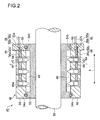
- FIG.2 is a longitudinal section of a hydraulic machine according to one embodiment.
- a hydraulic machine 40 illustrated in FIG.2 configures the hydraulic pump 22 or the hydraulic motor 28.
- the hydraulic machine 40 comprises a plurality of cylinders 42 formed along the radial direction of the hydraulic machine 40, a plurality of pistons provided slidably in the plurality of cylinders 42, respectively, and a cylinder block in which the plurality of cylinders 42 is provided.
- the cylinders 42 are disposed at equal intervals in the circumferential direction and axial direction (arrow a) of the cylinder block 48.
- Each of the pistons 44 is configured to reciprocate in the cylinder 42 along the radial direction of the hydraulic machine 40. In response to the reciprocating motion of each of the piston 44, volume of a hydraulic chamber r formed by the piston 44 and the cylinder 42 changes cyclically.
- the cylinder block 48 As some of the functions that the cylinder block 48 is expected to serve, there are the function of forming the cylinder 24 as the slide part for guiding the piston 44 slidably and the function of forming a structure for supporting the cylinder 42.
- the cylinder sleeve 64 and the cylinder block body 66 can share the functions expected in the cylinder block 48 (formation of the cylinder 42 and formation of the structure). This enables designing of the cylinder sleeve 64 and the cylinder block body 66 according to their respective functions, hence achieving reduced weight of the cylinder block 48 as a whole.
- an operating oil space s2 is formed.
- the hydraulic pressure acting on the valve element 99 via the operating oil space s2 exceeds the pressing force of the spring 100, the spring type on-off valve is released and hence the operating oil space s2 communicates with the high-pressure oil discharge pipe 96.
- the casing 94 for the high-pressure valve block 92 and the casing 106 for the low-pressure valve block 104 are configured such that a top cover 103 belonging to the casing 94 and a top cover 116 belonging to the casing 106 are formed separately from the casing body and mounted on the casing body by fastening embers (e.g. bolts) 118.
- fastening embers e.g. bolts
- the projection 148 is inserted in the small diameter section 142 to prevent the axial movement of the roller 46.
- the restraining arm 90 illustrated in FIG.9 in the piston 44 Therefore, it is not necessary to adapt the axial direction dimension of the roller 46 to the restraining arm 90. This enhances the degree of freedom in designing the roller 46.
- a supply line 156 is formed to supply the operating oil as lubricating oil to the lubrication part from the hydraulic chamber r formed by the piston 44 and the cylinder 42.
- the supply line 156 for supplying the lubricating oil to the lubrication part 154 can be formed in the piston 44 and in the cylindrical part 150 instead of outside the cylinder 42. As a result, it is possible to achieve smooth rotation of the ring member 152 relative to the cylindrical member 150 with a simple configuration.
- the distance between two pistons 44 in the axial direction of the roller 46 is 6x, whereas the distance between a supporting point of the piston 44 and the edge of the roller 46 is x.
- the following relationship is satisfied, (the distance between the support areas of the pistons 44 in the axial direction of the roller 46) > (a distance twice as large as the distance between the edge of the roller 46 and the support area of the piston 44).
- the pistons 44 are configured so that a load at a position which is 3x apart from the support area of the piston 44 supporting the roller 46 toward the roller center in the axial direction of the roller 46 equals to a load at a position which is x apart from the support area toward the outside in the axial direction.
Abstract
Description
- The present disclosure relates to a radial piston hydraulic machine which is applicable to a hydraulic pump, a hydraulic motor or the like, as well as a wind turbine generator equipped with the radial piston hydraulic machine.
- From the perspective of preserving the global environment, power generating apparatuses which use renewable energy such as solar power and wind power are becoming popular. For instance, there is a wind turbine generator which converts wind energy into rotational energy of a rotor and further converts the rotational energy into electric power by means of a generator. In a conventional wind turbine generator, a rated rotation speed of the rotor is relatively small compared to a rated rotation speed of the generator and thus, a mechanical speed increaser (gear type) is provided between the rotor and the generator.
- Meanwhile, wind turbine generators are progressively made larger to improve power generation efficiency, and accordingly a speed increaser becomes heavier and more expensive. Thus, it is becoming popular to use a wind turbine generator adopting a hydraulic transmission configured by a hydraulic pump and a hydraulic motor, instead of a mechanical speed increaser. Normally, this type of hydraulic transmission is provided with a hydraulic pump driven by rotation of a rotor, a hydraulic motor coupled to a generator, and a hydraulic pipe for circulating pressurized oil between the hydraulic pump and the hydraulic motor. For instance, disclosed in
Patent Document 1 is a wind turbine generator configured to transmit rotational energy of a rotor rotated by wind power to a generator via a hydraulic transmission. - There is also a radial piston hydraulic machine having a plurality of pistons arranged radially. For instance, a radial piston hydraulic pump used for a power transmission apparatus is disclosed in
Patent Document 2. This hydraulic pump is provided with an outer race having a cam face on an inner peripheral surface and an inner race having a plurality of cylinders arranged radially to face the outer race. The plurality of cylinders of the inner race has a plurality of pistons configured to be slidable therein, and to each of the pistons, a ball is attached so as to contact the cam face. - Patent Document 3 discloses a radial piston hydraulic machine which serves as a drive train for a wind turbine generator. This radial piston hydraulic machine is provided with a piston which is reciprocable in a cylinder, a roller attached to the piston and a cam having a cam face contacting the roller.
-
- [Patent Document 1]
WO 2010/033035 - [Patent Document 2]
JP 2010-19192 A - [Patent Document 3]
US 2010/0040470 A - A radial piston hydraulic machine comprises a rotation shaft, a plurality of cylinders radially arranged around the rotation shaft, a plurality of pistons being reciprocable inside the plurality of cylinders, and a member, such as a cam, for transmitting a motion between the rotation shaft and the piston. The hydraulic pump is configured to discharge high pressure operating oil by rotating the rotation shaft using an external force and converting rotational motion of the rotation shaft into reciprocating motion of the piston. The hydraulic motor is configured to rotate the rotation shaft using the reciprocating motion of the piston which is supplied with the high pressure operating oil.
- During operation of the hydraulic machine, a moment around the shaft is sometimes generated at the piston due to the load transmitted from the cam. This moment may results in generation of a phenomenon called skew in which the piston rotates around the cylinder axis with the roller. Once this phenomenon occurs, the shaft direction of the roller does coincide with the axial direction of the cam and thus, a high stress is generated in part between the roller and the cam. This makes it difficult to smoothly transmit the power between the roller and the cam, which can result in performance decrement of the radial piston hydraulic machine.
- It is an object of at least one embodiment of the present invention to suppress generation of the skew phenomenon of the roller in the radial piston hydraulic machine.
- To achieve the above object, a radial piston hydraulic machine according to at least one embodiment of the present invention comprises:
- a plurality of pistons;
- at least one roller;
- a cylinder block comprising a plurality of cylinders configured to guide the plurality of pistons reciprocably along a radial direction of the hydraulic machine, respectively;
- a cam configured to contact each of the at least one roller,
- wherein each of the at least one roller is provided for n pistons of the plurality of pistons, the n pistons being aligned along an axial direction of the hydraulic machine to share said each of the at least one roller, n being an integer not less than two.
- In these embodiments, each of the rollers is supported by the pistons at two or more points that are different in the axial direction of the hydraulic machine. In the conventional single-point supporting method for supporting the roller by the piston at one point, there is a room for rotational movement of the roller around the axis of the piston. However, by supporting the roller at two or more points in the axial direction, the rotational movement of the roller is suppressed. This effectively suppresses generation of the skew phenomenon of the roller. As a result, it is possible to prevent generation of partial stress between the cam and the roller. This enables smooth transmission of the power between the cam and the roller. Further, by supporting the roller at two or more supporting points in the axial direction, it is possible to effectively increase a load carrying capacity of the roller between the supporting points. Thus, even if the length of the roller is increased in the axial direction, it is possible to support the roller reliably.
- The above hydraulic machine is includes a hydraulic pump and a hydraulic motor, and the present invention is applicable to both the hydraulic pump and the hydraulic motor. Further, there are a hydraulic machine which has a rotation part inside the cylinder block and a hydraulic machine which has a rotation part outside the cylinder block. In the former hydraulic machine, the ring cam is an outward ring cam having a cam face facing outward. In the latter hydraulic machine, the ring cam is an inward ring cam having a cam face facing inward. The present invention is applicable to both of these.
- Further, the piston is arranged in the cylinder to reciprocate along the radial direction of the hydraulic machine. The term "along", however, not just refers to a state of being strictly parallel in a geometric sense with respect to a reference direction or object as a reference but also includes a state of being at an angle to a certain extent with respect the radial direction of the hydraulic machine (e.g. 30° or less).
- In some embodiments, the cam is a ring cam having a plurality of lobes disposed along a circumferential direction of the hydraulic machine, the ring cam being arranged to face the plurality of pistons and being configured rotatable so that the lobes move relative to the plurality of pistons in the circumferential direction, the plurality of cylinders includes a cylinder array that is formed by n cylinders of the plurality of cylinders arranged along the axial direction corresponding to the n pistons, and the plurality of lobes extends linearly in the axial direction over an area in the axial direction occupied by the cylinder array.
- In the above radial piston hydraulic machine, the plurality of lobes extends linearly in the axial direction over the area in the axial direction occupied by the cylinder array. This enables smooth relative rotation of the roller relative to the lobes, the roller corresponding to the n cylinders aligned in the axial direction in the same manner as the plurality of lobes. Further, as the plurality of lobes extends linearly in the axial direction over the area in the axial direction occupied by the cylinder array, it simplifies the configuration of the ring cam and also facilitates work for installing the ring cam. Therefore, it is possible to improve productivity of the radial piston hydraulic machine.
- In some embodiments, each of the at least one roller includes a cylindrical part extending along the axial direction over a region where the n pistons are provided, and the cylindrical part is configured to contact the cam over the region in the axial direction. As are result, the contact area of the roller with respect to the cam face can be increased in the axial direction of the roller, it is possible to reduce a contact surface pressure per unit contact area of the roller with respect to the cam face. Therefore, in these embodiments, it is possible to prevent fatigue fracture of the roller, the ring cam, the pistons and the like, in addition to the skew suppressing effect.
- In some embodiments, each of the at least one roller includes at least one contact part configured to contact and engage with the cam and at least one engagement part having a diameter smaller than the at least one contact part and the engagement part being configured to engage with the n pistons. In these embodiments, in addition to the skew suppressing effect, there are following advantages. As the engagement part of the roller with respect to the piston has a small diameter, it is possible to arrange the cylinder near the rotation part. This has the advantage of compact configuration of the cylinder block accommodating the cylinder.
- In some embodiments, each of the at least one roller includes a cylindrical member which is fixed to the n pistons and at least one ring member configured to contact the cam at an outer periphery and to rotate around the cylindrical member, and each of the at least one ring member includes a lubrication part to be supplied with lubricating oil, the lubrication part being provided on an inner periphery of said ring member.
- In this case, the cylindrical member is supported by the ring member via an oil film of the lubricating oil. This allows, to some extent, for a relative movement of the cylindrical member relative to the ring member (e.g. tilting of the cylindrical member relative to the ring member, where the axis of the cylindrical member tilts relative to the axis of the ring member). Thus, even if there is difference in position or dimension among the n pistons and the n cylinders due to manufacture tolerance, this difference in size and dimension can be absorbed by the relative movement between the ring member and the cylindrical member so that the n pistons can be reciprocated smoothly in the n cylinders.
- In each of the aforesaid n pistons and the cylindrical member, a supply line is provided for supplying operating oil of a hydraulic chamber formed by the piston and the cylinder as the lubricating oil to the lubrication part.
- By using as the lubricating oil the operating oil of the hydraulic chamber formed by the piston and the cylinder in the above manner, the supply line for supplying the lubricating oil to the lubrication part can be formed in the piston and in the cylindrical part, instead of outside the cylinder. As a result, it is possible to attain the above effect of smooth reciprocating of the n pistons in the n cylinders, with a simple configuration.
- Each of the aforesaid n pistons has a piston circumferential surface which is crowned so that an outer diameter of an end of the piston in an axial direction of the piston is smaller than an outer diameter of a center of the piston in the axial direction.
- With this configuration of the
piston 44, even when the axes of the n pistons sharing the one roller are tilted relative to the axes of the n cylinders, respectively, it is possible to prevent contact (seizure) of an edge part of the piston head belonging to each of the pistons with respect to the inner peripheral surface of the cylinder. Thus, even if there is difference in position or dimension among a plurality of the cylinders and a plurality of the pistons due to manufacture tolerance, assembling thereof can be easy. Further, even if there is difference in position or dimension among a plurality of the cylinders and a plurality of the pistons due to manufacture tolerance, the pistons can be reciprocated smoothly in the cylinders, respectively. - In some embodiments, an oil supply valve is also provided to collectively change a supply state of operating oil to n hydraulic chambers formed by the n pistons and n cylinders of the plurality of cylinders corresponding to the n pistons, respectively. With this configuration, only one oil supply valve is needed for supplying the operating oil to the n hydraulic chambers and thus, the number of the oil supply valves can be reduced. As a result, it is possible to simply the configuration of the hydraulic machine.
- In some embodiments, the cylinder block comprises: a cylinder cartridge having at least one cylinder of n cylinders of the plurality of cylinders corresponding to the n pistons; a cylinder block body having a cartridge hole into which the cylinder cartridge is inserted, and the hydraulic machine further comprises a cover member attached to the cylinder block body so as to restrict the cylinder cartridge inserted in the cartridge hole, so to prevent it from coming out from the cylinder block body along the radial direction.
- By mounting the cover member on the cylinder block body, it is easy to restrict the cylinder cartridge from coming out from the cylinder block body.
- In some embodiments, the cylinder block comprises: a cylinder cartridge having n cylinders of the plurality of cylinders corresponding to the n pistons; and a cylinder block body having a cartridge hole into which the cylinder cartridge is inserted, and the cylinder cartridge is configured to be removable from and insertable into the cylinder block body in such a state that the n pistons are integrated with the roller corresponding to the n pistons.
- When the roller or the n pistons need to be replaced due to influence of the frictional wear or the like, the roller and the n pistons can be replaced in a unitized state. This reduces workload for replacing the parts and also facilitates maintenance of the hydraulic machine.
- In some embodiments, the cylinder cartridge is configured removable from the cylinder block body to an opposite side of the cam in a radial direction of the hydraulic machine in such a state that the cylinder cartridge is integrated with a valve for controlling a state of communication between a hydraulic chamber formed by the piston and the cylinder and an outside of the hydraulic chamber.
- At the replacement of the valve, the valve is replaced in the state where the cylinder cartridge is integrated with the valve. This reduces workload for replacing the valve and also facilitates maintenance of the hydraulic machine. Further, the cylinder cartridge can be removed without removing the cam from the hydraulic machine and without causing interference between the cylinder cartridge and the cam. This further facilitates the replacement work of the cylinder cartridge.
- In some embodiments, the cylinder block is configured to be separable into a plurality of segments each of which includes n cylinders of the plurality of cylinders corresponding to the n pistons.
- By using the cylinder block which is separable per each of the segments which includes n cylinders associated with one roller that is shared by n pistons as described above, one roller, n pistons and one segment of the cylinder block holding the roller and the n pistons can be integrally removed and attached at the replacement thereof. Therefore, this facilitates assembling and disassembling of the cylinder block including the rollers, the pistons and the cylinders. This also facilitates maintenance and inspection of the roller, the piston and the like.
- In some embodiments, the cylinder block body is formed in a continuous manner over an entire circumference in a circumferential direction of the hydraulic machine.
- For instance, in the case where the hydraulic machine constitutes a hydraulic machine for a drive train of a wind turbine generator, when replacing a part of the segments at the site, the wind load acts on the cylinder block to some extent. Thus, immediately after the segment is removed, the positions of remaining segments are slightly displaced. This makes it difficult to mount a new segment. In view of this, by forming the cylinder block body in a continuous manner over the entire circumference in the circumferential direction of the hydraulic machine, it is possible to solve problems resulting from assembling of the segments.
- In some embodiments, the plurality of cylinders is provided on a moving path of n cylinders of the plurality of cylinders corresponding to the n pistons when the n cylinders are (virtually) moved in a spiral or spiral-like manner around an axis of the hydraulic machine.
- By arranging a plurality of the cylinders in this manner, a contact position of the cam and an edge of each roller supporting the n pistons can be easily distributed in the axial direction of the hydraulic machine. Thus, even if the contact surface pressure between the cam and the roller is locally high near the edge of the roller, as the contact position of the edge of each roller and the cam is distributed in the axial direction, it is possible to effectively suppress generation of scratches and friction wear on the cam surface.
- A wind turbine generator according to some embodiments of the present invention comprises:
- at least one blade;
- a hub on which the at least one blade is mounted;
- a hydraulic pump configured to be driven by rotation of the hub;
- a hydraulic motor configured to be driven by pressurized oil generated by the hydraulic pump; and
- a generator configured to be driven by the hydraulic motor,
- wherein at least one of the hydraulic pump or the hydraulic motor is a radial piston hydraulic machine,
- wherein the radial piston hydraulic machine comprises: a plurality of pistons; at least one roller; a cylinder block comprising a plurality of cylinders configured to guide the plurality of pistons reciprocably along a radial direction of the hydraulic machine, respectively; and a cam configured to contact each of the at least one roller, and
- wherein each of the at least one roller is provided for n pistons of the plurality of pistons, the n pistons being arranged along an axial direction of the hydraulic machine to share said each of the at least one roller, n being an integer not less than two.
- As a result, by supporting the roller by at least two points that are apart in the axial direction, it is possible to effectively suppress generation of the skew phenomenon at the roller. Therefore, it is possible to suppress generation of partial stress between the cam and the roller. This enables smooth transmission of the power between the cam and the roller. Further, by supporting the roller at two or more supporting points in the axial direction, it is possible to effectively increase a load carrying capacity of the roller between the supporting points. Thus, even if the length of the roller is increased in the axial direction, it is possible to support the roller reliably. Therefore, it is possible to achieve smooth operation of the radial piston hydraulic machine and also to improve power generation efficiency of the wind turbine generator.
- According to some embodiments of the present invention, each roller is provided for n pistons that are aligned along an axial direction of the hydraulic machine, n being an integer not less than two and thus, the roller is supported at two or more points that are apart from each other in the axial direction. This effectively suppresses generation of the skew phenomenon at the roller. As a result, it is possible to suppress generation of partial stress between the cam and the roller and also to prevent generation of partial stress between the cam and the roller. This enables smooth transmission of the power between the cam and the roller. Further, by supporting the roller at two or more supporting points that are apart in the axial direction, it is possible to effectively increase a load carrying capacity of the roller between the supporting points. Thus, even if the length of the roller is increased in the axial direction, it is possible to support the roller reliably.
-
- [
FIG.1 ]
FIG.1 is an illustration of a wind turbine generator to which a radial piston hydraulic machine according to one embodiment is applied. - [
FIG.2 ]
FIG.2 is a cross-sectional view of a hydraulic machine according to one embodiment. - [
FIG.3 ]
FIG.3 is a schematic view of oil paths of the hydraulic machine according to one embodiment. - [
FIG.4 ]
FIG.4 is an oblique view of a part of a cylinder block of the hydraulic machine according to one embodiment. - [
FIG.5 ]
FIG.5 is an oblique view of a modification example of the cylinder block. - [
FIG.6 ]
FIG.6 is an oblique view of a part of the cylinder block according to one embodiment. - [
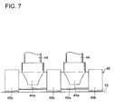
FIG.7 ]
FIG.7 is a front view of a configuration example of a piston and a roller according one embodiment. - [
FIG.8 ]
FIG.8 is a cross-sectional view of a cylinder block body and a cylinder assembly according to one embodiment. - [
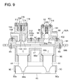
FIG.9 ]
FIG.9 is a cross-sectional view of the cylinder assembly according to one embodiment. - [
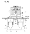
FIG.10 ]
FIG.10 is a cross-sectional view of the cylinder assembly according to one embodiment. - [
FIG.11 ]
FIG.11 is a cross-sectional view of a part of the cylinder block according to one embodiment. - [
FIG.12 ]
FIG. 12 is a front view of a configuration example of the piston and the roller according one embodiment. - [
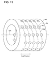
FIG.13 ]
FIG. 13 is an oblique view of the cylinder block according to one embodiment. - [
FIG.14 ]
FIG. 14 is an expansion view of the cylinder block according to one embodiment. - [
FIG.15 ]
FIG.15 is a local sectional view of a configuration example of the piston and the roller according to one embodiment. - [
FIG.16 ]
FIG. 16 is an illustration of a configuration example of the piston and the roller according to one embodiment, showing load distribution at positions in an axial direction of the roller. - Embodiments of the present invention will now be described in detail with reference to the accompanying drawings. It is intended, however, that unless particularly specified, dimensions, materials, shapes, relative positions and the like of components described in the embodiments shall be interpreted as illustrative only and not limitative of the scope of the present invention.
- First, some embodiments are now described in reference to
FIG.1 to FIG.4 . -
FIG.1 is a schematic illustration of a configuration example of a wind turbine generator to which a radial piston hydraulic machine according to one embodiment is applicable. Awind turbine generator 10 illustrated inFIG.1 comprises arotor 12 configured by at least one and typically at least twoblades 14 and ahub 16 to which theblades 14 are radially connected. Thehub 16 may be covered by ahub cover 18. Ahydraulic pump 22 is connected to therotor 12 via arotation shaft 12. Ahydraulic motor 28 is connected to thehydraulic pump 22 via a highpressure oil line 24 and a lowpressure oil line 26. More specifically, an outlet of thehydraulic pump 22 is connected to an inlet of thehydraulic motor 28 via the highpressure oil line 24, while an inlet of thehydraulic pump 22 is connected to an outlet of thehydraulic motor 28 via the lowpressure oil line 26. - The
hydraulic pump 22 is driven by therotation shaft 20 to pressurize operating oil, thereby generating high pressure operating oil (pressurized oil). The pressurized oil generated by thehydraulic pump 22 is supplied to thehydraulic motor 28 via the highpressure oil line 24 to drive thehydraulic motor 28. The operating oil having performed work in thehydraulic motor 28 turns into low pressure operating oil. This low pressure operating oil is returned to thehydraulic pump 22 via the lowpressure oil line 26. - Further, a
generator 30 is connected to thehydraulic motor 28. Thegenerator 30 is a synchronous generator configured to be driven by thehydraulic motor 28 and is connected to a grid not shown. - The
rotor shaft 20 is at least in part covered by anacelle 32. Thehydraulic pump 22, thehydraulic motor 28 and thegenerator 30 are installed inside thenacelle 32 installed to an upper end of thetower 34. In this embodiment and other embodiments described below, at least one of thehydraulic pump 22 or thehydraulic motor 28 is the radial piston hydraulic machine which is described hereinafter. -
FIG.2 is a longitudinal section of a hydraulic machine according to one embodiment. Ahydraulic machine 40 illustrated inFIG.2 configures thehydraulic pump 22 or thehydraulic motor 28. Thehydraulic machine 40 comprises a plurality ofcylinders 42 formed along the radial direction of thehydraulic machine 40, a plurality of pistons provided slidably in the plurality ofcylinders 42, respectively, and a cylinder block in which the plurality ofcylinders 42 is provided. Thecylinders 42 are disposed at equal intervals in the circumferential direction and axial direction (arrow a) of thecylinder block 48. Each of thepistons 44 is configured to reciprocate in thecylinder 42 along the radial direction of thehydraulic machine 40. In response to the reciprocating motion of each of thepiston 44, volume of a hydraulic chamber r formed by thepiston 44 and thecylinder 42 changes cyclically. - A
rotation shaft 50 is centrally arranged inside thecylinder block 48. In the case where thehydraulic machine 40 is thehydraulic pump 22, therotation shaft 50 is provided integrally with therotor shaft 20 or configured to rotate in interlink with therotor shaft 20. Aring cam 52 is mounted to an outer peripheral surface of therotation shaft 50. Thering cam 52 is configured to rotate with therotation shaft 50 and has a cam face contacting aroller 46 provided to thepiston 44. In this case, to cause a relative rotational motion of thering cam 52 relative to theroller 46, at least onebearing 54a may be provided between thecylinder block 26 and thering cam 52. - The reciprocating motion of the
piston 44 which accompanies cyclic volume change of the hydraulic chamber r is convertible into a rotational motion of thering cam 52, and vice versa. For instance, in the case where thehydraulic machine 40 is thehydraulic pump 22, the rotational motion of thering cam 52 rotating with therotation shaft 50 is converted into a reciprocating motion of thepiston 44. As a result, the volume of the hydraulic chamber r changes cyclically, thereby generating high pressure operating oil in the hydraulic chamber r. This high pressure oil is used to drive thehydraulic motor 28. - In the case where the
hydraulic machine 40 is thehydraulic motor 28, the reciprocating motion of thepiston 44 occurs in response to feeding of this high pressure oil to thehydraulic motor 28 from thehydraulic pump 22. Then, the reciprocating motion of thepiston 44 is converted into the rotational motion of thering cam 52. As a result, therotation shaft 50 of thehydraulic machine 40 rotates with thering cam 52. In this manner, by the movement of thering cam 52, the energy is converted between rotational energy (mechanical energy) of therotation shaft 50 of thehydraulic machine 40 and fluid energy of the operating oil. Therefore, thehydraulic machine 40 is capable of serving an intended function as thehydraulic pump 22 or thehydraulic motor 28. - In the
cylinder block 48, at least one inner oil path 56 (56a, 56b) communicating with a plurality of the hydraulic chambers r is formed. In one embodiment, a plurality of the inner oil paths 56 (56a, 56b) is provided along the axial direction of thehydraulic machine 40. Further, anend plate 60 is provided at one end face of thecylinder block 48. Theend plate 60 is an annular plate member. An annular collecting path 58 (58a, 58b) communicating with the plurality of inner oil paths 56 (56a, 56b) is formed in theendplate 60. In one embodiment, thebearing 54b is provided between theendplate 60 and thering cam 52, and theendplate 60 can be maintained in a stationary state without being affected by the rotational motion of thering cam 52. - The annular collecting paths 58 (58a, 58b) are respectively connected to outer pipes 62 (62a, 62b). In this manner, each of the hydraulic chambers r is configured to communicate with the outer pipes 62 (62a, 62b) via the inner oil paths 56 (56a, 56b) and the annular collecting paths 58 (58a, 58b). In some embodiments, the
cylinder block 48 includes a plurality ofcylinder sleeves 64 as cylinder cartridges which formcylinders 42, and acylinder block body 66 having a plurality ofsleeve holes 66a into which the plurality ofcylinder sleeves 64 is inserted, respectively. - As some of the functions that the
cylinder block 48 is expected to serve, there are the function of forming thecylinder 24 as the slide part for guiding thepiston 44 slidably and the function of forming a structure for supporting thecylinder 42. By providing thecylinder sleeve 64 and thecylinder block body 66 separately as described above, thecylinder sleeve 64 and thecylinder block body 66 can share the functions expected in the cylinder block 48 (formation of thecylinder 42 and formation of the structure). This enables designing of thecylinder sleeve 64 and thecylinder block body 66 according to their respective functions, hence achieving reduced weight of thecylinder block 48 as a whole. -
FIG.3 is a schematic view of oil paths for supplying or discharging the operating oil with respect to thehydraulic machine 40. InFIG.3 ,branch oil paths valves 72a, 72b are provided in thebranch oil paths inner oil paths inner oil paths - The on-off
valves 72a, 72b are controlled so as to open or close in synchronization with the rotational motion of thering cam 52 in the circumferential direction. Specifically, in a cycle where theroller 46 contacting the cam face of thering cam 52 moves from a bottom dead center toward the top dead center, the on-off valve provided in the oil discharge path is opened while the on-off valve provided in the oil supply path is closed. Further, in a cycle where theroller 46 moves from the top dead center toward the bottom dead center, the on-off valve provided in the oil supply path is opened while the on-off valve provided in the oil discharge path is closed. As the on-offvalves 72a, 72b, electromagnetic valves or spring-type on-off valves may be used, for instance. The spring-type on-off valve is provided with a spring for energizing a valve element toward a seat surface and is configured to move the valve element between an closed position and an open position by using a hydraulic pressure of the hydraulic chamber r and a balance between an elastic force of the spring and the hydraulic pressure. - In an exemplary embodiment illustrated in
FIG.3 , thering cam 52 has a plurality of crest portions (a plurality of lobes) 74a disposed along a circumferential direction of thehydraulic machine 20 to contact therollers 46. On the cam face of thering cam 52, the plurality of crest portions (the plurality of lobes) 74a and a plurality oftrough portions 74b are alternately arranged along the circumferential direction. Thelobes 74a move in the circumferential direction in response to rotation of thering cam 52. -
FIG.4 is an oblique view of a part of thecylinder block 48. Thecylinder block 48 is configured to be separable into a plurality ofsegments 48a in the circumferential direction. In onesegment 48a,n cylinder sleeves 64 are arranged corresponding to n pistons (n being an integer not less than 2). Specifically, acylinder array 76 is disposed in onesegment 48a, and thecylinder array 76 is formed by n cylinders 42 (seeFIG.2 ) disposed in the axial direction in correspondence to the n pistons. A holdingpart 44a is formed at an end of thepiston 44 provided in each of then cylinder sleeves 64 so as to surround theroller 46 from both sides. Oneroller 46 having a cylindrical shape is rotatably held by a plurality of the holdingparts 44a belonging, respectively, to the plurality ofpistons 44. The outer peripheral surface of thepiston 44 has a stepless configuration without step difference. Then cylinder sleeves 64 are aligned in the axial direction of the cylinder sleeve 64 (in the direction of arrow a), and theroller 46 extends along the axial direction. An arc-shapednotch 64a is formed at an end of thecylinder sleeve 64 so that theroller 46 enters thenotch 64a when thepiston 44 reaches the top dead center. - The
lobe 74a of thering cam 52 is configured to extend linearly in the axial direction over an axial area L occupied by thecylinder array 76. Further, theroller 46 is disposed along the extending direction of thelobe 74a and contacts the cam face. Theroller 46 has a cylindrical shape, and its outer peripheral surface has a stepless configuration to contact the cam face of thering cam 52 across the entire area in the axial direction. - As illustrated in
FIG.5 , in the case where the number of thecylinder sleeves 64 in the axial direction is large, thecylinder block 48 may be formed bysegments 48a so that thecylinder block 48 is separable into thesegments 48a not only in the circumferential direction but in the axial direction. - The
cylinder block 48 may have the configuration which his not separable into segments in the circumferential direction or the axial direction. Specifically, thecylinder block body 66 may be formed to be continuous across the entire circumference in the circumferential direction (the direction of arrow b ofFIG.4 ) of thehydraulic machine 40. For instance, in the case where thehydraulic machine 40 constitutes a hydraulic machine for a drive train of a wind turbine generator, when thesegments 48a needs to be partially replaced at the site, the wind load impinges on thecylinder block 48 to some extent. Thus, immediately after thesegment 48a is removed, the positions of remaining segments are slightly displaced. This makes it difficult to mount a new segment. In view of this, by forming thecylinder block body 66 in a continuous manner over the entire circumference in the circumferential direction of thehydraulic machine 40, it is possible to solve problems resulting from assembling of thesegments 48a. - In the embodiment illustrated in
FIG.4 andFIG.5 , theroller 46 is provided for the n pistons aligned in the axial direction of the hydraulic machine in the axial direction of the roller 46). Specifically, theroller 46 is held at multiple places that are apart from one another in the axial direction of theroller 46, by means of then pistons 44. Thus, it is possible to prevent the axis of theroller 48 from moving away from a ridge line direction of thelobe 74a. This suppresses generation of the skew phenomenon of theroller 46. Further, by supporting theroller 46 at multiple points, theroller 46 can be supported reliably. As a result, it is possible to suppress generation of partial stress between thering cam 52 and theroller 46. This enables smooth transmission and conversion of the power and prevents performance decrement of thehydraulic machine 40. Further, as theroller 46 contact the cam face over the entire axial area of theroller 46, the contact area of theroller 46 with respect to the cam face can be increased in the axial direction. Thus, it is possible to reduce the contact surface pressure between theroller 46 and the cam face. Even if the diameter of theroller 46 is relatively small, it is possible to keep the contact surface pressure in an appropriate range and also possible to prevent fatigue fracture of theroller 46, thering cam 52, thepistons 44 and the like. - As it is possible to reduce the contact surface pressure of the
roller 46 with respect to the cam face, it is no longer necessary to increase a diameter of a roller-side section of thepiston 44. Thus, the outer diameter of thepiston 44 can be the same on the hydraulic chamber side and on the roller side. This allows the stepless configuration of the outer peripheral surface of thepiston 44. Therefore, it is possible to facilitate machining of thepiston 44 and thecylinder sleeve 64 and also to achieve reduced cost. Further, thelobe 74a of thering cam 52 is configured to extend linearly in the axial direction and thus, it is possible to improve the degree of freedom in arranging theroller 46 which is provided for then pistons 44 aligned in the axial direction of thehydraulic machine 40. - As the
cylinder block 48 is separable by eachsegment 48a, it is easy to assemble and disassemble thecylinder block 48. This makes it easy to perform maintenance and replace parts that are arranged inside thecylinder block 48. Further, by configuring thecylinder sleeve 64 to be removable from thecylinder block 48, it is easy to attach and remove thecylinder sleeve 64 and also to perform maintenance and inspection of thecylinder sleeve 64. - Next, another configuration example of the
n pistons 44 and theroller 46 is described in reference toFIG.6 andFIG.7 . Theroller 46 illustrated inFIG.6 andFIG.7 has asection 46a and anothersection 46b. Thesection 46a is held by the holdingpart 44a of thepiston 44 and has a diameter different from that of thesection 46b. Specifically, the diameter of thesection 46a is smaller than the diameter of thesection 46b. The small-diameter section 46a and the large-diameter section 46b are concentrically arranged, and a stepped portion is formed between the small-diameter section 46a and the large-diameter section 46b. The small-diameter section 46a (an engagement part) is configured to engage with thepiston 44. The large-diameter section 46b is configured so that the outer periphery contacts the cam face4. The rest of the configuration is substantially the same as the embodiment described in reference toFIG.1 to FIG.4 . - With the above configuration, it is possible to arrange the
cylinder sleeve 64 and thepiston 44 closer to thering cam 52. Thus, it has the advantage of compact configuration of thecylinder block 48 accommodating thecylinder sleeve 64. - Next, a configuration example in which the
n pistons 44 and theroller 46 are configured as a cartridge is described in reference toFIG.8 andFIG.9 . The embodiment illustrated inFIG.8 andFIG.9 is one example in which thehydraulic machine 40 composes thehydraulic pump 22. As illustrated inFIG.8 , a plurality of cartridge holes 80 having an oval shape is formed in thecylinder block body 66 in the circumferential direction. Acylinder assembly 82A is installed in each of the cartridge holes 80. The configuration of thecylinder assembly 82A is explained below. - As illustrated in
FIG.8 andFIG.9 , thecylinder assembly 82A has anoval base plate 84. The area of thebase plate 84 is larger than the area of thecartridge hole 80, and thebase plate 84 has an oval shape similar to the shape of thecartridge hole 80. As illustrated inFIG.9 , acylinder cartridge 86 is mounted on thebase plate 84. In thecylinder cartridge 86 as a cylinder casing, n hydraulic chambers r (n being an integer not smaller than 2) are formed. Thecylinder cartridge 86 is mounted on one surface of thebase plate 84 and fastened to thebase plate 84 by fastening members 88 (e.g. bolts). - In the
cylinder cartridge 86a, between the chambers r of thecylinder cartridge 86a, apartition wall 86a is formed at a position nearer to thebase plate 84 than a position of apressure receiving face 44b of thepiston 44 at the top dead center. Between thepartition wall 86a and thebase plate 84, an operating oil space s1 is formed to communicate with each of the hydraulic chambers r of thecylinder cartridge 86a. Preferably each of the hydraulic chambers r is at the same distance from the operating oil space s1. Thebase plate 84 has acommunication hole 84a formed therein. Thecommunication hole 84a is preferably arranged in a center region of thebase plate 84 and to face the operating oil space s1. The end of each of thepistons 44 clasps onecommon roller 46 from both sides and has a holdingpart 44a for rotatably holding theroller 46. - A retaining
arm 90 is integrally provided in the holdingpart 44a of thepiston 44 disposed on each side of theroller 46. A needle-like retaining end 90a projecting from the retainingarm 90 contacts the center of theroller 46 to restrict movement of theroller 46 in the axial direction. As the center of theroller 46 does not rotate, there is no friction between the retainingend 90a and theroller 46. Therefore, there is no frictional wear between these parts. In this manner, the movement of theroller 46 in the axial direction is restricted by the retainingarms 90. - On the other surface of the
base plate 84, a highpressure valve block 92 and a lowpressure valve block 104 are mounted. Acasing 94 which forms the highpressure valve block 92 is detachably mounted on thebase plate 84 by fastening members (e.g. bolts) 102. A high-pressureoil discharge pipe 96 is provided in thecasing 94. In a space formed inside thecasing 94, a spring-type on-offvalve 98 is provided. The spring type on-offvalve 98 is configured by aspherical valve element 99 and acoil spring 100. Avalve seat 94a is formed on an inner wall of thecasing 94. Thecoil spring 100 is configured to apply a pressing force for pressing thevalve element 99 to thevalve seat 94a. Between thevalve seat 94a and thecommunication hole 84a, an operating oil space s2 is formed. When the hydraulic pressure acting on thevalve element 99 via the operating oil space s2 exceeds the pressing force of thespring 100, the spring type on-off valve is released and hence the operating oil space s2 communicates with the high-pressureoil discharge pipe 96. - A
casing 106 which forms the lowpressure valve block 104 is detachably mounted on thebase plate 84 by fastening members (e.g. bolts) 115. A low-pressure oil supply pipe 108 is connected to thecasing 106. In thecasing 106, anelectromagnetic valve 110 is provided. A coil 114 is provided around avalve rod 112 of theelectromagnetic valve 110. The electric current flowing in the coil 114 generates a force that moves thevalve rod 112. Avalve seat 106a is formed inside thecasing 106, and acoil spring 113 is provided inside the coil 114. When the electric current flows through the coil 114, a force in the direction of approaching thevalve seat 106a acts on thevalve element 111 of theelectromagnetic valve 110 to block communication between the operating oil space s2 and the low-pressure oil supply pipe 108. When the electric current does not flow in the coil 114, the valve element 11 is unseated from thevalve seat 106a by the spring force of thecoil spring 113, and hence the low-pressure oil supply pipe 108 communicates with the operating oil space s2. -
Holes 84b are formed in thebase plate 84 near its outer edge, and thecylinder assembly 82A is inserted in thecartridge hole 80 of thecylinder block 66 and then installed in thecylinder block body 66 by fastening members (e.g. bolts) via theholes 84b. In a plurality of thecylinder assemblies 82A installed in thecylinder block body 66, the reciprocating motion of thepiston 44 causes the high pressure oil to be discharged from the hydraulic chamber r to the high-pressureoil discharge pipe 96 and the operating oil to be supplied to the low-pressure oil supply pipe 108 from the hydraulic chamber r. - In the
cylinder assembly 82A, anelectromagnetic valve 110 is provided as an oil supply valve to collectively change a supply state of the operating oil to n hydraulic chambers r formed by then pistons 44 and then cylinder cartridges 86, respectively. As a result, only one oil supply valve is needed for the n hydraulic chambers r and thus, the number of the oil supply valves can be reduced and thecylinder block 48 can be reduced in size and cost. - Further, in the
cylinder assembly 82A, a spring-type on-off valve is provided as an oil discharge valve to collectively change a discharge state of the operating oil from the n hydraulic chambers r formed by then pistons 44 and then cylinder cartridges 86, respectively. As a result, only one oil discharge valve is needed for the n hydraulic chambers r and thus, the number of the oil discharge valves can be reduced and thecylinder block 48 can be reduced in size and cost. - The
n pistons 44 and theroller 46 illustrated inFIG.8 andFIG.9 constitute thecylinder assembly 82A as a cartridge which is detachable integrally with the cylinder casing with respect to thecylinder block body 66. As a result, when theroller 46 or then pistons 44 need to be replaced due to influence of the frictional wear or the like, thecylinder assembly 82A can be replaced simply by removing thecylinder assembly 82A from thecylinder block body 66 and installing anew cylinder assembly 82A. This facilitates maintenance of thehydraulic machine 40. - The
cylinder assembly 82A is configured removable from thecylinder block body 66 to an opposite side of thecam 52 in the radial direction of the hydraulic machine 40 (the direction of arrow P). As a result, to replace thecylinder assembly 82A, thecylinder assembly 82A alone can be removed without removing thecam 52 from thehydraulic machine 40 and this causes no interference between thecylinder assembly 82A and thecam 52. As a result, this further facilitates the replacement work of thecylinder assembly 82A. - As for the
cylinder assembly 82A, the operating oil spaces s1 and s2 are formed in communication with each of the hydraulic chambers r, an inlet of the high-pressure valve block 92 and an inlet of the low-pressure valve block 104 face the operating oil space s2, and these valve blocks are arranged with the same distance from thecommunication hole 84a. This makes it possible to supply or discharge the operating oil equally with respect to each of the hydraulic chambers r and these valve blocks. Therefore, the surface pressure can be generated equally over the entire contact area of the axiallylong roller 46 with respect to the cam face. As a result, thehydraulic machine 40 can operate smoothly, and uneven wear does not occur on thelobe 74a and the cam face of thering cam 52, which result in enhanced life of these parts. - Further, as for the
cylinder assembly 82A, thecasing 94 for the high-pressure valve block 92 and thecasing 106 for the low-pressure valve block 104 are configured such that atop cover 103 belonging to thecasing 94 and atop cover 116 belonging to thecasing 106 are formed separately from the casing body and mounted on the casing body by fastening embers (e.g. bolts) 118. Thus, at the maintenance and inspection, the top covers 103, 116 can be removed to facilitates the maintenance and inspection of the components arranged in the casing. - Next a
cylinder assembly 82B which is a modified example of thecylinder assembly 82A is described in reference toFIG.10. FIG.10 illustrates one example in which thehydraulic machine 40 composes thehydraulic pump 22. As for thecylinder assembly 82B of the embodiment illustrated inFIG.10 , thecylinder cartridge 86, thepiston 44 and therollers 46 which have the same configuration as those of the embodiment illustrated usingFIG.8 andFIG.9 , are mounted on one surface of abase plate 120. Thus, these components are given the same reference numerals as those of the embodiment illustrated usingFIG.8 andFIG.9 and are not explained further. - The common operating oil space s1 is formed to communicate with each of the hydraulic chambers r. The
base plate 120 has acommunication hole 120a formed in its center region. On the outer edge of thebase plate 120,holes 120b are formed. Thebase plate 120 is mounted on thecylinder block body 66 using fastening members (e.g. bolts) via theholes 120b. - On the other surface of the
base plate 120, a spring-type on-offvalve 126 having the same configuration as the spring-type on-offvalve 98 illustrated inFIG.9 and anelectromagnetic valve 128 having the same configuration as theelectromagnetic valve 110 illustrated inFIG.9 are aligned along the radial direction of the hydraulic machine 40 (a direction of arrow c). On the other surface of thebase plate 120, acasing 122 and acasing 124 are arranged along the radial direction of thehydraulic machine 40 and are joined together by a fastening member. The on-offvalve 126 is provided in thecasing 122, and theelectromagnetic valve 128 is provided in thecasing 124. The operating oil space s2 is formed between thebase plate 120 and the spring-type on-offvalve 126, and an inlet of theelectromagnetic valve 128 communicates with the operating oil space s2 via anoil path 130 formed in thecasing 122. - In the
casing 122, a high pressureoil discharge path 132 is formed communicating with the operating oil space s2 via the on-offvalve 126. In thecasing 124, a low pressureoil supply path 134 is formed communicating with theoil path 130 via theelectromagnetic valve 128. A plurality of thepistons 44 connected to oneroller 46 move in synchronization. When each of thepistons 44 approaches the top dead center and each of the hydraulic chambers 3 becomes pressurized, the spring-type on-offvalve 126 opens to discharge the high pressure oil to the high pressureoil discharge path 132. When each of thepistons 44 approaches the bottom dead center, theelectromagnetic valve 128 opens to supply the low pressure oil to each of the hydraulic chambers r from the low pressureoil discharge path 134. - According to this embodiment, in addition to the effects similar to those obtained in the embodiment illustrated by
FIG.8 andFIG.9 , it is possible to downsize the casings which incorporate the spring-type on-offvalve 126 and theelectromagnetic valve 128, as thecasings hydraulic machine 40 can accommodate the spring-type on-offvalve 126 and theelectromagnetic valve 128. Therefore, it is possible to downsize the valve block arranged on the outer side of thecylinder block body 66. - In the embodiment illustrated in
FIG.10 , thebase plate 120 and thecylinder block body 66 are joined together by fastening members penetrating theholes 120b formed in thebase plate 120. Alternatively, as illustrated inFIG.11 , acover member 129 may be provided to cover thewhole cylinder assembly 82B, and thecover member 129 and thecylinder block body 66 may be joined together by fasteningmembers penetrating holes 129a formed in thecover member 129. Thecover member 129 is configured to restrict thecylinder assembly 82B inserted in thecartridge hole 80 formed in thecylinder block body 66 from coming out from thecylinder block body 66 along the radial direction. By mounting thecover member 129 on thecylinder block body 66, it is possible to easily restrict thecylinder assembly 82B from coming out from thecylinder block body 66. Further, thecover member 129 covers thewhole cylinder assembly 82B and thus, it is possible to effectively restrict thecylinder assembly 82B from coming out from thecylinder block body 66. - Another configuration example of the
roller 46 and thepiston 44 is described in reference toFIG.12. FIG.12 is an illustration of the configuration example for preventing the roller from moving in the axial direction. In the embodiment illustrated inFIG.12 , in the same manner as the foregoing embodiments, oneroller 46 is rotatably held by the holdingparts 44a of thepistons 44. Theroller 46 has a steppedportion 140 in a region between thepistons 44, and this region forms asmall diameter section 142. In other region of theroller 46, alarge diameter section 144 which is larger in diameter than thesmall diameter section 142. Thelarge diameter section 144 contacts the cam face. Aframe 146 is provided between thepistons 44 and adjacent to the outer periphery of theroller 46. In theframe 146, aprojection 148 is formed, which projects toward theroller 46 and is freely fitted to the steppedportion 140. - In the embodiment illustrated in
FIG.12 , theprojection 148 is inserted in thesmall diameter section 142 to prevent the axial movement of theroller 46. Thus, it is not necessary to provide the restrainingarm 90 illustrated inFIG.9 in thepiston 44. Therefore, it is not necessary to adapt the axial direction dimension of theroller 46 to the restrainingarm 90. This enhances the degree of freedom in designing theroller 46. - In reference to
FIG.13 andFIG.14 , a disposition example of thecylinders 42 is described.FIG.13 is an oblique view of thecylinder block 48, andFIG.14 is an expansion view of thecylinder block 48 illustrated inFIG.13 . In some embodiments, thehydraulic machine 40 can be configured similarly to the configuration described in reference toFIG.1 to FIG.4 , except for the disposition of thecylinders 42 illustrated inFIG.13 andFIG.14 . - As for the
cylinder block 48 illustrated inFIG. 13 andFIG. 14 , a plurality of thecylinders 42 is provided on a movingpath 102 of thecylinder array 76 when thecylinder array 76 is moved in a spiral or spiral-like manner around anaxis 101 of thehydraulic machine 40. Thecylinder array 76 is formed byn cylinders 42 aligned along the axial direction of thehydraulic machine 40 corresponding to n pistons. By arranging a plurality of thecylinders 42 in this manner, a contact position Q (seeFIG.4 ) between an edge of theroller 46 supporting then pistons 44 and thecam 52 can be easily distributed in the axial direction of thehydraulic machine 40. Thus, even if the contact surface pressure between thecam 52 and theroller 46 is locally high near the edge of theroller 46, as the contact position Q between the edge of eachroller 46 and thecam 56 is distributed in the axial direction, it is possible to effectively suppress generation of scratches and friction wear on the cam surface. - Next, another configuration example of the
roller 46 and thepiston 44 is described in reference toFIG.15 . Theroller 46 illustrated inFIG.15 includes acylindrical member 150 which is fixed ton pistons 44 and aring member 152 configured to contact the cam at a peripheral surface and to rotate around thecylindrical member 150. Herein, thecylindrical member 150 is fixed to thepistons 44 so as not to rotate relative to thepistons 44. Thering member 152 includes alubrication part 154 on an inner periphery of thering member 152 to be supplied with lubricating oil. In this case, thecylindrical member 150 is supported by thering member 152 via an oil film of the lubricating oil. This allows, to some extent, for the movement of thecylindrical member 150 relative to the ring member 152 (e.g. tilting of thecylindrical member 150 relative to thering member 152, where the axis of thecylindrical member 152 tilts relative to the axis of the ring member 152). Thus, even if there is difference in position or dimension among then pistons 44 sharing the oneroller 46 and then cylinders 42 corresponding to then pistons 44 due to manufacture tolerance, this difference in size and dimension can be absorbed by the relative movement between thering member 152 and thecylindrical member 150 so that then pistons 44 can be reciprocated smoothly in then cylinders 42. - Inside each of the
n pistons 44 and inside thecylindrical member 150 that are illustrated inFIG.15 , asupply line 156 is formed to supply the operating oil as lubricating oil to the lubrication part from the hydraulic chamber r formed by thepiston 44 and thecylinder 42. - By using as the lubricating oil the operating oil of the hydraulic chamber r formed by the
piston 44 and thecylinder 42, thesupply line 156 for supplying the lubricating oil to thelubrication part 154 can be formed in thepiston 44 and in thecylindrical part 150 instead of outside thecylinder 42. As a result, it is possible to achieve smooth rotation of thering member 152 relative to thecylindrical member 150 with a simple configuration. - On the peripheral surface of the
cylindrical member 150 illustrated inFIG.15 , asupply port 158 is provided to supply the lubricating oil from thesupply line 156 to thelubrication part 154. Thesupply port 158 is provided in the peripheral surface of thecylindrical member 150 on a side (thecam 52 side) opposite to the hydraulic chamber r. As a result, the pressure of the oil film acts on thering member 152 against the force that thering member 152 receives from thecam 52. Thus, even if the force that thering member 152 receives from thecam 52 changes due to a pressure change in the hydraulic chamber r, it is possible to maintain the oil film between thering member 152 and thecylindrical member 150. This action works strongly in the period when the pressure in the hydraulic chamber is relatively high and the oil film is prone to deficiency. Thus, it is possible to favorably maintain the oil film even when the pressure in the hydraulic chamber changes. - The
supply line 156 illustrated inFIG.15 is provided with a seal member 159 in a boundary area between thepiston 44 and thecylindrical member 150. As a result, even in the case where thesupply line 156 is provided inside thepiston 44 and inside thecylindrical member 150, it is possible to supply the lubricating oil from the hydraulic chamber r to thesupply port 158 while preventing leaking of the lubricating oil in the boundary area between thepiston 44 and thecylindrical member 150 by means of the seal member 159. - As described above, the
roller 46 illustrated inFIG.15 comprises acylindrical member 150 which is fixed to thepiston 44 and does not rotate, and aring member 152 which is rotatable around thecylindrical member 150. Specifically, theroller 46 is configured such that theentire roller 46 does not rotate but at least a part of theroller 46 rotates. - Next, an example shape of the
piston 44 is described in reference toFIG.16 . Thepiston 44 illustrated inFIG. 16 is formed into a shape of a barrel. In other words, thepiston 44 includes a pistonperipheral surface 160 which is crowned such that an outer diameter R2 of an axial direction end of the piston 44 (a piston head) is smaller than an outer diameter R1 of an axial direction center part of thepiston 44. - With this configuration of the
piston 44, even when the axes of then pistons 44 sharing the oneroller 46 are tilted relative to the axes of then cylinders 42 respectively, it is possible to prevent contact (seizure) of an edge part of the piston head belonging to each of thepistons 44 with respect to the inner peripheral surface of thecylinder 42. Thus, even if there is difference in position or dimension among a plurality of thecylinders 42 and a plurality of thepistons 44 due to manufacture tolerance, assembling thereof can be easy. Further, even if there is difference in position or dimension among a plurality of thecylinders 42 and a plurality of thepistons 44 due to manufacture tolerance, thepistons 44 can be reciprocated smoothly in thecylinders 42, respectively. - The shape of the
piston 44 illustrated inFIG.16 (the outer diameter R2 of the piston head being smaller than the outer diameter R1 of the axial direction center part of the piston 44) is also applicable to pistons of any one of the embodiments described in reference to other drawings. The shapes of thepistons 44 may be made different from one another. For instance, in the case where threepistons 44 are provided for oneroller 46 and aligned in the axial direction of theroller 46, thepistons 44 may have the following configurations. The pistonperipheral surfaces 160 of these threepistons 44 may be configured such that a ratio (R2/R1) of the outer diameter R2 of the piston head to the outer diameter R1 of the piston axial center part is greater in onepiston 44 disposed in the middle than other two pistons. In this case, the force (a side force) along the circumferential direction of thehydraulic machine 40 concentrates on themiddle piston 44 among these threepistons 44 and the other twopistons 44 is not subjected to a large force. Therefore, themiddle piston 44 bears the side force and the other twopistons 44 stabilize supporting of theroller 46 supported by the threepistons 44. - Further, a distance between support areas of adjacent two of the
n pistons 44 in the axial direction of theroller 46 may be made more than two times as large as a distance between the edge of theroller 46 and an end of the support area of thepiston 44 disposed at each end of theroller 46. The support area of thepiston 44 indicates the area where theroller 46 is supported by thispiston 44. - In the exemplary embodiment illustrated in
FIG.16 , the distance between twopistons 44 in the axial direction of theroller 46 is 6x, whereas the distance between a supporting point of thepiston 44 and the edge of theroller 46 is x. In other words, the following relationship is satisfied, (the distance between the support areas of thepistons 44 in the axial direction of the roller 46) > (a distance twice as large as the distance between the edge of theroller 46 and the support area of the piston 44). In this case, as illustrated inFIG.16 , thepistons 44 are configured so that a load at a position which is 3x apart from the support area of thepiston 44 supporting theroller 46 toward the roller center in the axial direction of theroller 46 equals to a load at a position which is x apart from the support area toward the outside in the axial direction. - As described above, by supporting the
roller 46 by at least two places that are apart in the axial direction, it is possible to effectively increase a load capacity of theroller 46 between the support areas. Thus, it is possible to support theroller 46 in a stable manner even in the case where the axial length of theroller 46 is increased for the purpose of reducing the contact surface pressure between theroller 46 and thecam 52, or the like. -
- 10
- Wind turbine generator
- 12
- Rotor
- 14
- Blade
- 16
- Hub
- 18
- Hub cover
- 20
- Rotor shaft
- 22
- Hydraulic pump
- 24
- High pressure oil line
- 26
- Low pressure oil line
- 28
- Hydraulic motor
- 30
- Generator
- 32
- Nacelle
- 34
- Tower
- 40
- Hydraulic machine
- 42
- Cylinder
- 44
- Piston
- 44a
- Holding part
- 46
- Roller
- 46a, 142
- Small-diameter section
- 46b, 144
- Large-diameter section
- 48
- Cylinder block
- 50
- Rotation shaft
- 52
- Ring cam
- 54a, 54b
- Bearing
- 56, 56a, 56b
- Inner oil path
- 58, 58a, 58b
- Annular collecting oil path
- 60
- End plate
- 62, 62a, 62b
- Outer pipe
- 64
- Cylinder sleeve
- 64a
- Notch
- 66
- Cylinder block body
- 66a
- Sleeve hole
- 70a, 70b
- Branch oil path
- 72a, 72b
- On-off valve
- 74a
- Crest portion
- 74b
- Trough portion
- 80
- Cartridge hole
- 82A, 82B
- Cylinder assembly
- 84, 120
- Base plate
- 84a
- Communication hole
- 86
- Cylinder casing
- 86a
- Partition wall
- 88, 102
- Fastening member
- 90
- Arm
- 90a
- Retaining end
- 92
- High-pressure valve block
- 94, 106, 122, 124
- Casing
- 94a
- Valve seat
- 96
- High-pressure oil discharge pipe
- 98, 126
- Spring-type on-off valve
- 99
- Valve element
- 100
- Coil spring
- 103, 116
- Top cover
- 104
- Low-pressure valve block
- 108
- Low-pressure oil supply pipe
- 110, 128
- Electromagnetic valve
- 111
- Valve element
- 112
- Valve rod
- 113
- Coil spring
- 114
- Coil
- 129
- Cover member
- 129a
- Hole
- 130
- Oil path
- 132
- High-pressure oil discharge path
- 134
- Low-pressure oil supply path
- 140
- Stepped portion
- 142
- Cylinder array
- 146
- Frame
- 148
- Projection
- 150
- Cylindrical member
- 152
- Ring member
- 154
- Lubrication part
- 156
- Supply line
- 158
- Supply port
- 160
- Piston peripheral surface
- 164
- Seal member
- r
- Hydraulic chamber
- s1, s2
- Operating oil space
Claims (15)
- A radial piston hydraulic machine comprising:a plurality of pistons;at least one roller;a cylinder block comprising a plurality of cylinders configured to guide the plurality of pistons reciprocably along a radial direction of the hydraulic machine, respectively;a cam configured to contact each of the at least one roller,wherein each of the at least one roller is provided for n pistons of the plurality of pistons, the n pistons being aligned along an axial direction of the hydraulic machine to share said each of the at least one roller, n being an integer not less than two.
- The radial piston hydraulic machine according to claim 1,
wherein the cam is a ring cam having a plurality of lobes disposed along a circumferential direction of the hydraulic machine, the ring cam being arranged to face the plurality of pistons and being configured rotatable so that the lobes move relative to the plurality of pistons in the circumferential direction,
wherein the plurality of cylinders includes a cylinder array that is formed by n cylinders of the plurality of cylinders arranged along the axial direction corresponding to the n pistons, and
wherein the plurality of lobes extends linearly in the axial direction over an area in the axial direction occupied by the cylinder array. - The radial piston hydraulic machine according to claim 1 or 2,
wherein said each of the at least one roller includes a cylindrical part extending along the axial direction over a region where the n pistons are provided, and
wherein the cylindrical part is configured to contact the cam over the region in the axial direction. - The radial piston hydraulic machine according to claim 1 or 2,
wherein each of the at least one roller includes at least one contact part configured to contact and engage with the cam and at least one engagement part having a diameter smaller than the at least one contact part and the engagement part being configured to engage with the n pistons. - The radial piston hydraulic machine according to claim 1 or 2,
wherein each of the at least one roller includes a cylindrical member which is fixed to the n pistons and at least one ring member configured to contact the cam at an outer periphery and to rotate around the cylindrical member, and
wherein each of the at least one ring member includes a lubrication part to be supplied with lubricating oil, the lubrication part being provided on an inner periphery of said ring member. - The radial piston hydraulic machine according to claim 5,
wherein, in each of the n pistons and the cylindrical member, a supply line is provided for supplying operating oil of a hydraulic chamber formed by the piston and the cylinder as the lubricating oil to the lubrication part. - The radial piston hydraulic machine according to any one of claims 1 to 6,
wherein each of the n pistons has a piston circumferential surface which is crowned so that an outer diameter of an end of the piston in an axial direction of the piston is smaller than an outer diameter of a center of the piston in the axial direction. - The radial piston hydraulic machine according to any one of claims 1 through 7, further comprising:an oil supply valve for collectively changing a supply state of operating oil to n hydraulic chambers formed by the n pistons and n cylinders of the plurality of cylinders corresponding to the n pistons, respectively.
- The radial piston hydraulic machine according to any one of claims 1 through 8,
wherein the cylinder block comprises:a cylinder cartridge having at least one cylinder of n cylinders of the plurality of cylinders corresponding to the n pistons; anda cylinder block body having a cartridge hole into which the cylinder cartridge is inserted, andwherein the hydraulic machine further comprises a cover member attached to the cylinder block body so as to restrict the cylinder cartridge inserted in the cartridge hole, so to prevent it from coming out from the cylinder block body along the radial direction. - The radial piston hydraulic machine according to any one of claims 1 through 8,
wherein the cylinder block comprises:a cylinder cartridge having n cylinders of the plurality of cylinders corresponding to the n pistons; anda cylinder block body having a cartridge hole into which the cylinder cartridge is inserted, andwherein the cylinder cartridge is configured to be removable from and insertable into the cylinder block body in such a state that the n pistons are integrated with the roller corresponding to the n pistons. - The radial piston hydraulic machine according to claim 9 or 10,
wherein the cylinder cartridge is configured removable from the cylinder block body to an opposite side of the cam in a radial direction of the hydraulic machine in such a state that the cylinder cartridge is integrated with a valve for controlling a state of communication between a hydraulic chamber formed by the piston and the cylinder and an outside of the hydraulic chamber. - The radial piston hydraulic machine according to any one of claims 1 to 11,
wherein the cylinder block is configured to be separable into a plurality of segments each of which includes n cylinders of the plurality of cylinders corresponding to the n pistons. - The radial piston hydraulic machine according to any one of claims 9 to 11,
wherein the cylinder block body is formed in a continuous manner over an entire circumference in a circumferential direction of the hydraulic machine. - The radial piston hydraulic machine according to any one of claims 1 to 13,
wherein the plurality of cylinders is provided on a moving path of n cylinders of the plurality of cylinders corresponding to the n pistons when the n cylinders are moved in a spiral or spiral-like manner around an axis of the hydraulic machine. - A wind turbine generator comprising:at least one blade;a hub on which the at least one blade is mounted;a hydraulic pump configured to be driven by rotation of the hub;a hydraulic motor configured to be driven by pressurized oil generated by the hydraulic pump; anda generator configured to be driven by the hydraulic motor,wherein at least one of the hydraulic pump or the hydraulic motor is a radial piston hydraulic machine,wherein the radial piston hydraulic machine comprises:a plurality of pistons;at least one roller;a cylinder block comprising a plurality of cylinders configured to guide the plurality of pistons reciprocably along a radial direction of the hydraulic machine, respectively; anda cam configured to contact each of the at least one roller, andwherein each of the at least one roller is provided for n pistons of the plurality of pistons, the n pistons being arranged along an axial direction of the hydraulic machine to share said each of the at least one roller, n being an integer not less than two.
Applications Claiming Priority (2)
| Application Number | Priority Date | Filing Date | Title |
|---|---|---|---|
| JP2013055062A JP2014181578A (en) | 2013-03-18 | 2013-03-18 | Radial piston type hydraulic machine and wind power generation apparatus |
| JP2013267219A JP2015124609A (en) | 2013-12-25 | 2013-12-25 | Radial piston type hydraulic machine and wind power generation device |
Publications (2)
| Publication Number | Publication Date |
|---|---|
| EP2781744A2 true EP2781744A2 (en) | 2014-09-24 |
| EP2781744A3 EP2781744A3 (en) | 2014-10-29 |
Family
ID=50289488
Family Applications (1)
| Application Number | Title | Priority Date | Filing Date |
|---|---|---|---|
| EP14160384.5A Withdrawn EP2781744A3 (en) | 2013-03-18 | 2014-03-17 | Radial piston hydraulic machine and wind turbine generator |
Country Status (1)
| Country | Link |
|---|---|
| EP (1) | EP2781744A3 (en) |
Citations (3)
| Publication number | Priority date | Publication date | Assignee | Title |
|---|---|---|---|---|
| JP2010019192A (en) | 2008-07-11 | 2010-01-28 | Toyota Motor Corp | Piston pump and power transmission device equipped therewith, and piston motor |
| US20100040470A1 (en) | 2008-08-13 | 2010-02-18 | Jacob Johannes Nies | Wind energy system with fluid-working machine with non-symmetric actuation |
| WO2010033035A1 (en) | 2008-09-17 | 2010-03-25 | Chapdrive As | Turbine speed stabilisation control system |
Family Cites Families (1)
| Publication number | Priority date | Publication date | Assignee | Title |
|---|---|---|---|---|
| GB1085338A (en) * | 1965-07-02 | 1967-09-27 | Cessna Aircraft Co | Improvements in and relating to hydraulic reciprocating motors |
-
2014
- 2014-03-17 EP EP14160384.5A patent/EP2781744A3/en not_active Withdrawn
Patent Citations (3)
| Publication number | Priority date | Publication date | Assignee | Title |
|---|---|---|---|---|
| JP2010019192A (en) | 2008-07-11 | 2010-01-28 | Toyota Motor Corp | Piston pump and power transmission device equipped therewith, and piston motor |
| US20100040470A1 (en) | 2008-08-13 | 2010-02-18 | Jacob Johannes Nies | Wind energy system with fluid-working machine with non-symmetric actuation |
| WO2010033035A1 (en) | 2008-09-17 | 2010-03-25 | Chapdrive As | Turbine speed stabilisation control system |
Also Published As
| Publication number | Publication date |
|---|---|
| EP2781744A3 (en) | 2014-10-29 |
Similar Documents
| Publication | Publication Date | Title |
|---|---|---|
| US8358024B2 (en) | Wind turbine generator and tidal current generator with a hydraulic transmission | |
| CN102482957B (en) | Control valve | |
| EP2766601B1 (en) | Wind turbine generator | |
| EP2781744A2 (en) | Radial piston hydraulic machine and wind turbine generator | |
| EP2726737B1 (en) | Hydraulic motor or pump and wind turbine generator | |
| EP2770203A1 (en) | Radial piston fluid machine and power generating apparatus of renewable energy type | |
| JP2015124609A (en) | Radial piston type hydraulic machine and wind power generation device | |
| EP3141748B1 (en) | Hydraulic machine of radial-piston type and wind turbine power generating apparatus | |
| EP2749768B1 (en) | Radial piston hydraulic machine and wind turbine generator | |
| EP2896825B1 (en) | Renewable energy power generation device | |
| JP2014181578A (en) | Radial piston type hydraulic machine and wind power generation apparatus | |
| US20040255773A1 (en) | Rotary radial piston machine | |
| JP2023532674A (en) | multistage compressor | |
| EP2749769B1 (en) | Radial piston hydraulic machine and wind turbine generator | |
| EP2770201A1 (en) | Valve cylinder interface, assembling method for valve cylinder interface and power generating apparatus of renewable energy type | |
| EP3104006B1 (en) | Hydraulic machine and power generating apparatus of renewable energy type | |
| JP6363148B2 (en) | Renewable energy generator | |
| EP2739846B1 (en) | Fluid working machine and wind turbine generator | |
| JP2014129770A (en) | Radial piston type hydraulic machine, method for assembling the same, and wind power generation device | |
| EP2770202B1 (en) | Control valve, assembly method of control valve, and power generating apparatus of renewable energy type | |
| BR112013032575B1 (en) | downhole hydraulic pump | |
| JP2014129772A (en) | Radial piston type hydraulic machine and wind power generation device | |
| RU2258144C2 (en) | Multistage rotary machine | |
| JP2014129782A (en) | Radial piston type hydraulic machine and wind power generation device | |
| JP2014129775A (en) | Radial piston type hydraulic machine and wind power generation device |
Legal Events
| Date | Code | Title | Description |
|---|---|---|---|
| PUAI | Public reference made under article 153(3) epc to a published international application that has entered the european phase |
Free format text: ORIGINAL CODE: 0009012 |
|
| 17P | Request for examination filed |
Effective date: 20140317 |
|
| AK | Designated contracting states |
Kind code of ref document: A2 Designated state(s): AL AT BE BG CH CY CZ DE DK EE ES FI FR GB GR HR HU IE IS IT LI LT LU LV MC MK MT NL NO PL PT RO RS SE SI SK SM TR |
|
| AX | Request for extension of the european patent |
Extension state: BA ME |
|
| PUAL | Search report despatched |
Free format text: ORIGINAL CODE: 0009013 |
|
| AK | Designated contracting states |
Kind code of ref document: A3 Designated state(s): AL AT BE BG CH CY CZ DE DK EE ES FI FR GB GR HR HU IE IS IT LI LT LU LV MC MK MT NL NO PL PT RO RS SE SI SK SM TR |
|
| AX | Request for extension of the european patent |
Extension state: BA ME |
|
| RIC1 | Information provided on ipc code assigned before grant |
Ipc: F04B 1/04 20060101AFI20140924BHEP Ipc: F03C 1/047 20060101ALI20140924BHEP Ipc: F03C 1/30 20060101ALI20140924BHEP Ipc: F04B 1/053 20060101ALI20140924BHEP |
|
| STAA | Information on the status of an ep patent application or granted ep patent |
Free format text: STATUS: THE APPLICATION IS DEEMED TO BE WITHDRAWN |
|
| 18D | Application deemed to be withdrawn |
Effective date: 20150430 |