EP2896496A1 - Method and system for determining and verifying ply orientation of a composite laminate - Google Patents
Method and system for determining and verifying ply orientation of a composite laminate Download PDFInfo
- Publication number
- EP2896496A1 EP2896496A1 EP15151541.8A EP15151541A EP2896496A1 EP 2896496 A1 EP2896496 A1 EP 2896496A1 EP 15151541 A EP15151541 A EP 15151541A EP 2896496 A1 EP2896496 A1 EP 2896496A1
- Authority
- EP
- European Patent Office
- Prior art keywords
- see
- composite laminate
- light source
- scanned image
- prepared edge
- Prior art date
- Legal status (The legal status is an assumption and is not a legal conclusion. Google has not performed a legal analysis and makes no representation as to the accuracy of the status listed.)
- Granted
Links
Images



Classifications
-
- G—PHYSICS
- G01—MEASURING; TESTING
- G01N—INVESTIGATING OR ANALYSING MATERIALS BY DETERMINING THEIR CHEMICAL OR PHYSICAL PROPERTIES
- G01N21/00—Investigating or analysing materials by the use of optical means, i.e. using sub-millimetre waves, infrared, visible or ultraviolet light
- G01N21/84—Systems specially adapted for particular applications
- G01N21/88—Investigating the presence of flaws or contamination
- G01N21/89—Investigating the presence of flaws or contamination in moving material, e.g. running paper or textiles
- G01N21/892—Investigating the presence of flaws or contamination in moving material, e.g. running paper or textiles characterised by the flaw, defect or object feature examined
- G01N21/898—Irregularities in textured or patterned surfaces, e.g. textiles, wood
-
- G—PHYSICS
- G01—MEASURING; TESTING
- G01N—INVESTIGATING OR ANALYSING MATERIALS BY DETERMINING THEIR CHEMICAL OR PHYSICAL PROPERTIES
- G01N21/00—Investigating or analysing materials by the use of optical means, i.e. using sub-millimetre waves, infrared, visible or ultraviolet light
- G01N21/84—Systems specially adapted for particular applications
- G01N21/88—Investigating the presence of flaws or contamination
- G01N21/8851—Scan or image signal processing specially adapted therefor, e.g. for scan signal adjustment, for detecting different kinds of defects, for compensating for structures, markings, edges
-
- B—PERFORMING OPERATIONS; TRANSPORTING
- B29—WORKING OF PLASTICS; WORKING OF SUBSTANCES IN A PLASTIC STATE IN GENERAL
- B29C—SHAPING OR JOINING OF PLASTICS; SHAPING OF MATERIAL IN A PLASTIC STATE, NOT OTHERWISE PROVIDED FOR; AFTER-TREATMENT OF THE SHAPED PRODUCTS, e.g. REPAIRING
- B29C70/00—Shaping composites, i.e. plastics material comprising reinforcements, fillers or preformed parts, e.g. inserts
- B29C70/04—Shaping composites, i.e. plastics material comprising reinforcements, fillers or preformed parts, e.g. inserts comprising reinforcements only, e.g. self-reinforcing plastics
- B29C70/06—Fibrous reinforcements only
- B29C70/10—Fibrous reinforcements only characterised by the structure of fibrous reinforcements, e.g. hollow fibres
- B29C70/16—Fibrous reinforcements only characterised by the structure of fibrous reinforcements, e.g. hollow fibres using fibres of substantial or continuous length
- B29C70/20—Fibrous reinforcements only characterised by the structure of fibrous reinforcements, e.g. hollow fibres using fibres of substantial or continuous length oriented in a single direction, e.g. roofing or other parallel fibres
- B29C70/202—Fibrous reinforcements only characterised by the structure of fibrous reinforcements, e.g. hollow fibres using fibres of substantial or continuous length oriented in a single direction, e.g. roofing or other parallel fibres arranged in parallel planes or structures of fibres crossing at substantial angles, e.g. cross-moulding compound [XMC]
-
- B—PERFORMING OPERATIONS; TRANSPORTING
- B29—WORKING OF PLASTICS; WORKING OF SUBSTANCES IN A PLASTIC STATE IN GENERAL
- B29C—SHAPING OR JOINING OF PLASTICS; SHAPING OF MATERIAL IN A PLASTIC STATE, NOT OTHERWISE PROVIDED FOR; AFTER-TREATMENT OF THE SHAPED PRODUCTS, e.g. REPAIRING
- B29C70/00—Shaping composites, i.e. plastics material comprising reinforcements, fillers or preformed parts, e.g. inserts
- B29C70/04—Shaping composites, i.e. plastics material comprising reinforcements, fillers or preformed parts, e.g. inserts comprising reinforcements only, e.g. self-reinforcing plastics
- B29C70/28—Shaping operations therefor
- B29C70/30—Shaping by lay-up, i.e. applying fibres, tape or broadsheet on a mould, former or core; Shaping by spray-up, i.e. spraying of fibres on a mould, former or core
-
- G—PHYSICS
- G01—MEASURING; TESTING
- G01B—MEASURING LENGTH, THICKNESS OR SIMILAR LINEAR DIMENSIONS; MEASURING ANGLES; MEASURING AREAS; MEASURING IRREGULARITIES OF SURFACES OR CONTOURS
- G01B11/00—Measuring arrangements characterised by the use of optical techniques
- G01B11/26—Measuring arrangements characterised by the use of optical techniques for measuring angles or tapers; for testing the alignment of axes
- G01B11/27—Measuring arrangements characterised by the use of optical techniques for measuring angles or tapers; for testing the alignment of axes for testing the alignment of axes
- G01B11/272—Measuring arrangements characterised by the use of optical techniques for measuring angles or tapers; for testing the alignment of axes for testing the alignment of axes using photoelectric detection means
-
- B—PERFORMING OPERATIONS; TRANSPORTING
- B29—WORKING OF PLASTICS; WORKING OF SUBSTANCES IN A PLASTIC STATE IN GENERAL
- B29C—SHAPING OR JOINING OF PLASTICS; SHAPING OF MATERIAL IN A PLASTIC STATE, NOT OTHERWISE PROVIDED FOR; AFTER-TREATMENT OF THE SHAPED PRODUCTS, e.g. REPAIRING
- B29C70/00—Shaping composites, i.e. plastics material comprising reinforcements, fillers or preformed parts, e.g. inserts
- B29C70/04—Shaping composites, i.e. plastics material comprising reinforcements, fillers or preformed parts, e.g. inserts comprising reinforcements only, e.g. self-reinforcing plastics
- B29C70/28—Shaping operations therefor
- B29C70/54—Component parts, details or accessories; Auxiliary operations, e.g. feeding or storage of prepregs or SMC after impregnation or during ageing
-
- G—PHYSICS
- G01—MEASURING; TESTING
- G01N—INVESTIGATING OR ANALYSING MATERIALS BY DETERMINING THEIR CHEMICAL OR PHYSICAL PROPERTIES
- G01N21/00—Investigating or analysing materials by the use of optical means, i.e. using sub-millimetre waves, infrared, visible or ultraviolet light
- G01N21/84—Systems specially adapted for particular applications
- G01N21/8422—Investigating thin films, e.g. matrix isolation method
- G01N2021/8438—Mutilayers
-
- G—PHYSICS
- G01—MEASURING; TESTING
- G01N—INVESTIGATING OR ANALYSING MATERIALS BY DETERMINING THEIR CHEMICAL OR PHYSICAL PROPERTIES
- G01N21/00—Investigating or analysing materials by the use of optical means, i.e. using sub-millimetre waves, infrared, visible or ultraviolet light
- G01N21/84—Systems specially adapted for particular applications
- G01N2021/8472—Investigation of composite materials
Definitions
- the disclosure relates generally to methods and systems for analyzing composite structures, and more particularly, to methods and systems for determining and verifying ply orientation of composite laminates used in composite structures, such as aircraft composite structures.
- Composite structures may be used in a wide variety of applications, including in the manufacture of aircraft, spacecraft, rotorcraft, watercraft, automobiles, and other vehicles and structures, due to their high strength-to-weight ratios, corrosion resistance and other favorable properties.
- composite structures may be used to form the tail sections, wings, fuselage and other component parts of the aircraft.
- Composite laminates used to form composite structures may be manufactured by laying up or stacking multiple layers or "plies" together and curing the lay-up.
- a single layer or ply typically consists of reinforcing fibers in a matrix material.
- the composite laminates may be stacked with plies of different ply orientations in a defined sequence per design and/or quality requirements to optimize performance, such as load-carrying capacity.
- the ply orientations may typically include 0° (zero degree) ply orientation, 90° (ninety degree) ply orientation, +45° (plus forty-five degree) / -45° (minus forty-five degree) ply orientation, or another suitable ply orientation. Determining the ply orientation of the composite laminates is important in optimizing composite laminate designs, as well as in complying with composite laminate design and/or quality requirements.
- inconsistencies may occur during the lay-up or stacking of the plies, such as, for example, misoriented plies, gaps, overlaps, or other inconsistencies.
- Methods and systems for determining and verifying ply orientation may be used to analyze the composite laminates for any possible inconsistencies and to ensure that the composite laminates manufactured by the lay-up or stacking process meet the design and/or quality requirements pertaining to ply orientation.
- Known methods and systems for determining and verifying ply orientation exist.
- such known methods and systems may require an extensive and time consuming polishing process of an edge or portion of a sample composite laminate to be analyzed.
- Such polishing process may be needed to obtain sufficient visibility of the fiber orientation of the composite laminate plies.
- the polishing process may require mounting the sample in an epoxy resin material, or a similar material, so that the sample may be secured in place during the polishing process. Such mounting process may be difficult with large samples that require polishing.
- such known methods and systems for determining and verifying ply orientation may require the use of a high magnification microscope, i.e., 100x or greater, to observe the individual fibers of the composite laminate plies of the sample. If the sample to be analyzed is larger than the field of view of the microscope, this may require obtaining multiple images of the composite laminate plies and editing the images together with a known photo editing software to obtain a continuous view of the sample under the microscope. This image preparation process may be time consuming and labor intensive.
- such known methods and systems for determining and verifying ply orientation may require additional cutting, polishing, and image processing steps to analyze fibers of the sample composite laminate having a +45° (plus forty-five degree) ply orientation and a -45° (minus forty-five degree) ply orientation.
- a second cut of the sample composite laminate may need to be made and the processes of mounting, polishing, and image processing may need to be performed for both cuts of the +45° (plus forty-five degree) ply orientation and the -45° (minus forty-five degree) ply orientation.
- the additional work needed to analyze +/-45° (plus/minus forty-five degree) plies may increase the overall time and costs of manufacturing.
- Example implementations of the present disclosure provide an improved method and system for determining and verifying ply orientation of a composite laminate to overcome the laborious nature of existing solutions. As discussed in the below detailed description, embodiments of the improved method and system for determining and verifying ply orientation of a composite laminate may provide significant advantages over existing methods and systems.
- a method for determining and verifying ply orientation of a composite laminate comprises the step of performing a first scan of a prepared edge of the composite laminate using an off-axis inclined light source directing light at a first angle to a first area on the prepared edge to produce a first scanned image.
- the method further comprises the step of rotating an orientation of the off-axis inclined light source relative to the prepared edge.
- the method further comprises the step of performing a second scan of the prepared edge using the off-axis inclined light source directing light at a second angle to the first area on the prepared edge to produce a second scanned image.
- the method further comprises the step of comparing the first scanned image and the second scanned image to determine a ply orientation of each ply of the composite laminate.
- the ply orientation is preferably determined based on light source reflections of the off-axis inclined light source.
- the steps of performing the first scan of the prepared edge and performing the second scan of the prepared edge comprise using a scanning device having an optical resolution of 1200 dpi (dots per inch) or greater. More preferably, the step of comparing the first scanned image and the second scanned image to determine the ply orientation comprises using a manual visual comparison of the light source reflections of the first scanned image and the second scanned image.
- the method further comprises the step of verifying the ply orientation of the composite laminate against a baseline ply orientation of a baseline composite laminate.
- the step of verifying the ply orientation of the composite laminate comprises verifying that a plurality of plies of the composite laminate are laid up correctly as intended by design.
- a method for determining and verifying ply orientation of a composite laminate of an aircraft composite structure comprises the step of preparing an edge of the composite laminate to obtain a prepared edge.
- the method further comprises the step of performing with a scanning device having at least one off-axis inclined light source a first scan of the prepared edge using the at least one off-axis inclined light source to direct light at a first angle to a first area on the prepared edge to produce a first scanned image.
- the method further comprises the step of rotating 180 degrees an orientation of the at least one off-axis inclined light source relative to the prepared edge, such that the off-axis inclined light source directs light at a second acute angle symmetrically opposite the first acute angle.
- the method further comprises the step of performing with the scanning device a second scan of the prepared edge using the at least one off-axis inclined light source to direct light at the symmetrically opposite second acute angle to the first area on the prepared edge to produce a second scanned image.
- the method further comprises the step of transferring the first scanned image and the second scanned image from the scanning device to a processing device for processing.
- the method further comprises the step of comparing the first scanned image and the second scanned image to determine a ply orientation of each ply of the composite laminate.
- the step of comparing the first scanned image and the second scanned image to determine the ply orientation comprises using at least one of a manual visual comparison and an automated comparison with a process software, of the light source reflections of the first scanned image and the second scanned image.
- the ply orientation is preferably determined based on light source reflections of the at least one off-axis inclined light source.
- the steps of performing the first scan (104) of the prepared edge (92a) and performing the second scan (126) of the prepared edge (92a) comprise performing with the scanning device (102) having a 45° (forty-five degree) light source (106a) and an optical resolution (122) of 1200 dpi (dots per inch) or greater.
- the method further comprises the step of preparing a baseline matrix comprising a baseline ply orientation of a baseline composite laminate of the aircraft composite structure.
- the method further comprises the step of verifying the ply orientation of the composite laminate against the baseline ply orientation of the baseline matrix.
- the step of comparing the first scanned image and the second scanned image to determine the ply orientation comprises determining the ply orientation based on light source reflections comprising bright/dark transition reflections in +/- 45° (plus/minus forty-five) degree plies to a cross-section surface of the prepared edge, dark reflections for plies normal to the cross-section surface of the prepared edge, and bright reflections for plies parallel to the cross-section surface of the prepared edge.
- a system for determining and verifying ply orientation of a composite laminate comprises a composite laminate that is cured and comprises at least one prepared edge and a plurality of plies, each ply having a ply orientation.
- the system further comprises a scanning assembly.
- the scanning assembly comprises a scanning device having at least one off-axis inclined light source configured to direct light at a first angle to a first area on the prepared edge of the composite laminate to illuminate and capture a first scanned image.
- the at least one off-axis inclined light source is further configured to direct light at a second angle to the first area on the prepared edge to illuminate and capture a second scanned image.
- the scanning assembly further comprises a processing device coupled to the scanning device. The processing device is configured to receive and process the first scanned image and the second scanned image from the scanning device.
- the composite laminate is a fiber-reinforced composite laminate comprised of continuous fibers
- the scanning device has an optical resolution of 1200 dpi (dots per inch) or greater.
- the scanning assembly further comprises a baseline matrix comprising a baseline ply orientation of a baseline composite laminate.
- the system provides a ply orientation determination of each ply of the composite laminate based on light source reflections of the at least one off-axis inclined light source and a comparison of the first scanned image and the second scanned image.
- the system further provides a ply orientation verification of the composite laminate using the baseline matrix.
- the processing device comprises a computer having process software to process the first scanned image and the second scanned image to enable comparison of the first scanned image and the second scanned image against each other and against the baseline matrix.
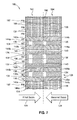
- FIG. 1 is an illustration of a perspective view of an aircraft 10 having one or more composite structures 12.
- the aircraft 10 comprises a fuselage 14, a nose 16, wings 18, engines 20, and an empennage 22 comprising horizontal stabilizers 24 and a vertical stabilizer 26.
- the one or more composite structures 12 may comprise a composite laminate 28.
- the composite laminate 28 (see FIG. 1 ), discussed in further detail below, is cured and is in the form of a fiber-reinforced composite laminate 28a (see FIG. 1 ).
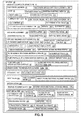
- Embodiments of the disclosure provide a method 66 (see FIG. 4A ) for determining and verifying ply orientation of the composite laminate 28 (see FIGS. 1 , 5 ), provide a method 80 (see FIG. 4B ) for determining and verifying ply orientation of the composite laminate 28 of the aircraft composite structure 12, and provide a system 90 (see FIG. 5 ) for determining and verifying ply orientation of the composite laminate 28 (see FIGS. 1 , 5 ).
- FIG. 2 is an illustration of a flow diagram of an embodiment of an aircraft manufacturing and service method 30.
- FIG. 3 is an illustration of a functional block diagram of an embodiment of an aircraft 50. Referring to FIGS. 2-3 , embodiments of the disclosure may be described in the context of the aircraft manufacturing and service method 30, as shown in FIG. 2 , and the aircraft 50, as shown in FIG. 3 .
- the exemplary aircraft manufacturing and service method 30 may include specification and design 32 (see FIG. 2 ) of the aircraft 50 (see FIG. 3 ) and material procurement 34 (see FIG. 2 ).
- component and subassembly manufacturing 36 see FIG. 2
- system integration 38 see FIG. 2
- the aircraft 50 (see FIG. 3 ) takes place. Thereafter, the aircraft 50 (see FIG. 3 ) may go through certification and delivery 40 (see FIG. 2 ) in order to be placed in service 42 (see FIG. 2 ). While in service 42 (see FIG. 2 ) by a customer, the aircraft 50 (see FIG. 3 ) may be scheduled for routine maintenance and service 44 (see FIG. 2 ), which may also include modification, reconfiguration, refurbishment, and other suitable services.
- Each of the processes of the aircraft manufacturing and service method 30 may be performed or carried out by a system integrator, a third party, and/or an operator (e.g., a customer).
- a system integrator may include, without limitation, any number of aircraft manufacturers and major-system subcontractors
- a third party may include, without limitation, any number of vendors, subcontractors, and suppliers
- an operator may include an airline, leasing company, military entity, service organization, and other suitable operators.
- the aircraft 50 produced by the exemplary aircraft manufacturing and service method 30 may include an airframe 52 with a plurality of systems 54 and an interior 56.
- examples of the systems 54 may include one or more of a propulsion system 58, an electrical system 60, a hydraulic system 62, and an environmental system 64. Any number of other systems may be included.
- an aerospace example is shown, the principles of the disclosure may be applied to other industries, such as the automotive industry.
- Methods and systems embodied herein may be employed during any one or more of the stages of the aircraft manufacturing and service method 30 (see FIG. 2 ).
- components or subassemblies corresponding to component and subassembly manufacturing 36 may be fabricated or manufactured in a manner similar to components or subassemblies produced while the aircraft 50 (see FIG. 3 ) is in service 42 (see FIG. 2 ).
- one or more apparatus embodiments, method embodiments, or a combination thereof may be utilized during component and subassembly manufacturing 36 (see FIG. 2 ) and system integration 38 (see FIG. 2 ), for example, by substantially expediting assembly of or reducing the cost of the aircraft 50 (see FIG. 3 ).
- apparatus embodiments, method embodiments, or a combination thereof may be utilized while the aircraft 50 (see FIG. 3 ) is in service 42 (see FIG. 2 ), for example and without limitation, to maintenance and service 44 (see FIG. 2 ).
- FIG. 4A in an embodiment of the disclosure, there is provided a method 66 for determining and verifying a ply orientation 98 (see FIG. 5 ) of the composite laminate 28 (see FIGS. 1 , 5 ).
- FIG. 4A is an illustration of a flow diagram of one of the embodiments of the method 66 for determining and verifying ply orientation 98 (see FIG. 5 ) of the composite laminate 28 (see FIG. 5 ).
- FIG. 4B in another embodiment of the disclosure, there is provided a method 80 for determining and verifying ply orientation 98 (see FIG. 5 ) of the composite laminate 28 (see FIGS. 1 , 5 ) of the aircraft composite structure 12 (see FIGS. 1 , 5 ).
- FIG. 4B is an illustration of a flow diagram of one of the embodiments of the method 80 for determining and verifying ply orientation 98 (see FIG. 5 ) of the composite laminate 28 (see FIG. 5 ) of the aircraft composite structure 12 (see FIGS. 1 , 5 ).
- FIG. 5 in another embodiment of the disclosure, there is provided a system 90 for determining and verifying ply orientation 98 of the composite laminate 28.
- FIG. 5 is an illustration of a functional block diagram of an embodiment of the system 90 for determining and verifying ply orientation 98 of the composite laminate 28.
- the method 66 comprises optional step 68 of preparing an edge 92 (see FIG. 5 ) of the composite laminate 28 (see FIG. 5 ) to obtain a prepared edge 92a (see FIG. 5 ).
- one or more edges 92 (see FIG. 5 ) of the composite laminate 28 (see FIG. 5 ) may become rough and may require one or more preparation treatments 93 (see FIG. 5 ), in order to obtain a prepared edge 92a (see FIG. 5 ) that is smooth or polished prior to undergoing the scanning steps of the method 66 (see FIG. 4A ), discussed below.
- the preparation treatments 93 see FIG.
- the preparation treatments 93 may be performed via a manual process, for example, manually by rubbing the edge 92 (see FIG. 5 ) with sandpaper or another abrading device, with a polishing or cleaning solution or device, or with another suitable manual preparation treatment.
- the preparation treatments 93 may be performed via an automated process, or via a combination of manual and automated processes.
- the step 68 of preparing the edge 92 may be performed in a short period of time, and preferably, in about ten (10) minutes to thirty (30) minutes, and more preferably, in about ten (10) minutes.
- This short preparation treatment time for preparing the edge 92 is advantageous, as compared to the mounting and polishing processes required in known methods for determining and verifying ply orientation, which may take hours or days to complete.
- the composite laminate 28 (see FIGS. 1 , 5 ) is preferably in the form of a fiber-reinforced composite laminate 28a (see FIGS. 1 , 5 ) comprised of a plurality of plies 94 (see FIG. 5 ).
- Preparing the edge 92 (see FIG. 5 ) of the composite laminate 28 (see FIGS. 1 , 5 ) to obtain the prepared edge 92a (see FIG. 5 ) preferably facilitates visibility of the plurality of plies 94 (see FIG. 5 ) at the prepared edge 92a (see FIG. 5 ), in scanned images of the prepared edge 92a, after the prepared edge 92a has been scanned, as discussed below.
- the plurality of plies 94 preferably comprise continuous fibers 96 (see FIG. 5 ) in a resin matrix material 97 (see FIG. 5 ).
- Continuous fibers 96 are preferred over discontinuous or chopped fibers. With continuous fibers 96 (see FIG. 5 ), there may be few, if any, breaks in the reinforcements, and continuous fibers 96 may provide improved performance properties of the composite laminate 28 (see FIG. 5 ).
- the continuous fibers 96 comprising the plurality of plies 94 (see FIG. 5 ) preferably comprise reinforcement or high-strength fibers made of one or more materials, such as carbon, glass, fiberglass, graphite, boron, aromatic polyamide, silicon carbide, or another suitable reinforcement or high-strength material.
- the resin matrix material 97 may comprise polymeric, ceramic, metallic or other matrix materials, such as epoxy, polyester, vinyl ester resins, polyetheretherketone polymer (PEEK), polyetherketoneketone polymer (PEKK), polyimides, bismaleimide, aluminum, titanium, alumina, or another suitable matrix material.
- "cured” means undergoing a full or partial hardening process, with or without heat, for example, the resin matrix material hardening to form a strong, rigid, fiber-reinforced composite laminate.
- the plurality of plies 94 (see FIG. 5 ) of the composite laminate 28 (see FIGS. 1 , 5 ) may comprise a prepreg unidirectional tape, a unidirectional fiber tape, a carbon fiber-reinforced plastic (CFRP) tape, or another suitable tape; a carbon fiber-reinforced plastic (CFRP) fabric, a prepreg fabric, a woven fabric including a woven carbon fiber fabric, or another suitable fabric; a combination of a tape or a fabric thereof; or another suitable composite material.
- CFRP carbon fiber-reinforced plastic
- the composite laminate 28 may be formed of a composite material by any suitable means including, but not limited to, hand lay up, automated lay up, or another suitable forming process.
- Each ply 94 (see FIG. 5 ) preferably has a ply orientation 98 (see FIG. 5 ).
- the ply orientation 98 (see FIG. 5 ) may be tailored to any ply direction desired.
- the ply orientation 98 (see FIG. 5 ) may include, without limitation, such ply orientations as: 0° (zero degree) ply orientation, where a ply orientation angle 190 (see FIG. 5 ) of the fiber is 0° (zero degrees) or parallel to a cross-section surface 114 (see FIGS.
- the fiber is +45° (plus forty-five degrees) / -45° (minus forty-five degrees) to the cross-section surface 114 (see FIGS. 5 , 6A ) of the prepared edge 92a (see FIG. 5 ), or another suitable ply orientation.
- ply orientation angle means the angle that the fibers of a ply make with a cross-section surface of a prepared edge of a composite laminate, or alternatively, the angle that the fibers of a ply make with a surface of a scanning device that a sample of the composite laminate is positioned on for image scanning.
- +45° (plus forty-five degrees) means that a ply is rotated 45° (forty-five degrees) clockwise relative to the orientation of an adjacent ply layer
- -45° (minus forty-five degrees) means that a ply is rotated 45° (forty-five degrees) counterclockwise relative to the orientation of an adjacent ply layer.
- the method 66 further comprises step 70 of performing a first scan 104 (see FIGS. 5 , 6A ) of the prepared edge 92a (see FIG. 5 ) of the composite laminate 28 (see FIG. 5 ).
- the first scan 104 (see FIG. 5 ) is preferably performed using an off-axis inclined light source 106 (i.e., a light source that is not perpendicular to the prepared edge 92a as shown in FIG. 5 ).
- the off-axis inclined light source 106 preferably directs light 108 (see FIG. 5 ) at a first acute angle 110 relative to the prepared edge 92a (i.e., an angle that is not perpendicular to the prepared surface as shown in FIG.
- the off-axis inclined light source 106 (see FIG. 5 ) illuminates the first area 112 (see FIG. 5 ) on the prepared edge 92a (see FIG. 5 ).
- the method 66 further comprises step 72 of rotating an orientation 117 (see FIG. 5 ) of the off-axis inclined light source 106 (see FIG. 5 ) at a rotation 125 (see FIG. 5 ) relative to the prepared edge 92a (see FIG. 5 ) of the composite laminate 28 (see FIG. 5 ).
- the step 72 of rotating the orientation 117 (see FIG. 5 ) of the off-axis inclined light source 106 (see FIG. 5 ) preferably comprises rotating the orientation 117 (see FIG. 5 ) of the off-axis inclined light source 106 in a 180 degree rotation 125a (see FIG. 5 ) relative to the prepared edge 92a (see FIG. 5 ) of the composite laminate 28 (see FIG. 5 ).
- the method 66 further comprises step 74 of performing a second scan 126 (see FIG. 5 ) of the prepared edge 92a (see FIG. 5 ) of the composite laminate 28 (see FIG. 5 ).
- the second scan 126 is preferably performed with the orientation of the off-axis inclined light source 106 (see FIG. 5 ) rotated 180 degrees from that of the first scan.
- the off-axis inclined light source 106 With the orientation of the off-axis inclined light source rotated 180 degrees relative that of the first scan, the off-axis inclined light source 106 (see FIG. 5 ) preferably directs light 108 (see FIG. 5 ) at a second acute angle 130 relative to the prepared edge 92a that is symmetrically opposite the first acute angle 110 (see FIG. 5 ), to direct light at a symmetrically opposite second acute angle 110 to the first area 112 (see FIG. 5 ) on the prepared edge 92a to produce a second scanned image 128 (see FIG. 5 ).
- the step 70 (see FIG. 4A ) of performing the first scan 104 (see FIG. 5 ) of the prepared edge 92a (see FIG. 5 ) and the step 74 (see FIG. 4A ) of performing the second scan 126 (see FIG. 5 ) of the prepared edge 92a (see FIG. 5 ) preferably comprise using a scanning device 102 (see FIG. 5 ) having a light source 106a (see FIG.
- first acute angle 110 is about 45° (forty-five degree) relative to the prepared surface and light directed at the second acute angle 130 is about 45° (forty-five degree) relative to the prepared surface and symmetrically opposite the first acute angle 110.
- the scanning device 102 is preferably a flatbed color image scanning device or another suitable scanning device.
- the scanning device 102 preferably has one or more off-axis inclined light sources 106 (see FIG. 5 ) housed within a housing 164 (see FIG. 6A ) of the scanning device 102 (see FIG. 6A ).
- the off-axis inclined light source 106 may comprise a fluorescent light source, such as a fluorescent lamp or a cold cathode fluorescent lamp; a xenon light source, such as a xenon lamp; LED (light-emitting diode) lights, or another suitable light source.
- the off-axis inclined light source 106 may be connected to a voltage regulator (not shown) to ensure consistency of light over the scan pass.
- the scanning device 102 may preferably have one off-axis inclined light source 106 (see FIG. 5 ).
- the scanning device 102 may have more than one off-axis inclined light source 106 (see FIG. 5 ), such as two off-axis inclined light sources 106 (see FIG. 5 ).
- the off-axis inclined light sources 106 see FIG. 5 for scanning of the composite laminate 28 (see FIG. 5 ) with the scanning device 102 (see FIG. 5 ) having two off-axis inclined light sources 106 (see FIG. 5 ).
- first off-axis inclined light source may be controlled so that a first off-axis inclined light source is turned on and a second off-axis inclined light source is turned off during the first scan 104 (see FIG. 5 ). Then, with the second scan 126 (see FIG. 5 ), the first off-axis inclined light source is turned off and the second off-axis inclined light source is turned on.
- the off-axis inclined light source 106 may direct light 108, for example, at a +45° (plus forty-five degree) angle to the first area 112 (see FIG. 5 ) on the prepared edge 92a (see FIG. 5 ).
- the orientation 117 (see FIG. 5 ) of the off-axis inclined light source 106 (see FIG. 5 ) may then be rotated preferably in a 180 degree rotation 125a (see FIG. 5 ) relative to the prepared edge 92a (see FIG. 5 ) of the composite laminate 28 (see FIG. 5 ).
- the off-axis inclined light source 106 may direct light 108 (see FIG. 5 ), for example, at a -45° (minus forty-five degree) angle to the first area 112 (see FIG. 5 ) on the prepared edge 92a (see FIG. 5 ).
- the off-axis inclined light source 106 may direct light 108, for example, at a +45° (plus forty-five degree) angle to the first area 112 (see FIG. 5 ) on the prepared edge 92a (see FIG. 5 ). Then, the composite laminate 28 (see FIG. 5 ) may be physically rotated 180 degrees and scanned, such that during the second scan 126 (see FIG. 5 ), the off-axis inclined light source 106 (see FIG. 5 ) directs light 108 (see FIG. 5 ), for example, at a -45° (minus forty-five degree) angle to the first area 112 (see FIG. 5 ) on the prepared edge 92a (see FIG. 5 ).
- the orientation 117 (see FIG. 5 ) of the off-axis inclined light source 106 (see FIG. 5 ) is effectively also rotated 180 degrees relative to the prepared edge 92a (see FIG. 5 ) of the composite laminate 28 (see FIG. 5 ).
- the step 70 (see FIG. 4A ) of performing the first scan 104 (see FIG. 5 ) of the prepared edge 92a (see FIG. 5 ) and the step 74 (see FIG. 4A ) of performing the second scan 126 (see FIG. 5 ) of the prepared edge 92a (see FIG. 5 ) preferably comprise using the scanning device 102 (see FIG. 5 ) having an optical resolution 122 (see FIG. 5 ) of 1200 dpi (dots per inch), or greater.
- the scanning device 102 (see FIG. 4A ) of performing the first scan 104 (see FIG. 5 ) of the prepared edge 92a (see FIG. 5 ) and the step 74 (see FIG. 4A ) of performing the second scan 126 (see FIG. 5 ) of the prepared edge 92a (see FIG. 5 ) preferably comprise using the scanning device 102 (see FIG. 5 ) having an optical resolution 122 (see FIG. 5 ) of 1200 dpi (dots per inch
- the scanning device 102 may have other suitable resolutions and speeds.
- An example of a scanning device that may be used with the method 66 (see FIG. 4A ), the method 80 (see FIG. 4B ), and the system 90 (see FIG. 5 ) disclosed herein, includes, but is not limited to, an EPSON flatbed scanning device from Epson America, Inc. of Long Beach, California. (EPSON is a registered trademark of Seiko Epson Kabushiki Kaisha DBA Seiko Epson Corporation of Tokyo, Japan.) However, other suitable scanning devices may also be used.
- the method 66 further comprises step 76 of comparing the first scanned image 116 (see FIG. 5 ) and the second scanned image 128 (see FIG. 5 ) to determine the ply orientation 98 (see FIG. 5 ) of each ply 94 (see FIG. 5 ) of the composite laminate 28 (see FIG. 5 ).
- the ply orientation 98 (see FIG. 5 ) is preferably determined based on light source reflections 124 (see FIG. 5 ) of the off-axis inclined light source 106 (see FIG. 5 ).
- the step 76 (see FIG. 4A ) of comparing the first scanned image 116 (see FIG. 5 ) and the second scanned image 128 (see FIG. 5 ) to determine the ply orientation 98 (see FIG. 5 ) comprises a manual visual comparison 146a (see FIG. 5 ) of the light source reflections 124 (see FIG. 5 ) of the first scanned image 116 (see FIG. 5 ) and the second scanned image 128 (see FIG. 5 ).
- the manual visual comparison 146a is performed by one or more operators of the method 66 (see FIG. 4A ).
- the step 76 (see FIG. 4A ) of comparing the first scanned image 116 (see FIG. 5 ) and the second scanned image 128 (see FIG. 5 ) to determine the ply orientation 98 (see FIG. 5 ) comprises using an automated comparison 146b (see FIG. 5 ) with a process software 154 (see FIG. 5 ) to compare the light source reflections 124 (see FIG. 5 ) of the first scanned image 116 (see FIG. 5 ) and the second scanned image 128 (see FIG. 5 ).
- the ply orientation 98 may comprise using a combination of the manual visual comparison 146a (see FIG. 5 ) and the automated comparison 146b (see FIG. 5 ) with the process software 154 (see FIG. 5 ).
- the step 76 (see FIG. 4A ) of comparing the first scanned image (see FIG. 5 ) and the second scanned image 128 (see FIG. 5 ) to determine the ply orientation 98 (see FIG. 5 ) preferably comprises determining the ply orientation 98 (see FIG. 5 ) based on light source reflections 124 (see FIG. 5 ).
- the light source reflections 124 comprise bright/dark transition reflections 144a, 144b (see FIG. 5 ) in plies 142 (see FIG. 5 ) off-axis to the cross-section surface 114 (see FIG. 5 ) of the prepared edge 92a (see FIG.
- the light source reflections 124 further comprise dark reflections 136 (see FIG. 5 ) for plies 134 (see FIG. 5 ) normal or perpendicular to the cross-section surface 114 (see FIG. 5 ) of the prepared edge 92a (see FIG. 5 ), such as 90° (ninety degree) plies.
- the light source reflections 124 further comprise bright reflections 140 (see FIG. 5 ) for plies 138 (see FIG. 5 ) parallel to the cross-section surface 114 (see FIG. 5 ) of the prepared edge 92a (see FIG. 5 ), such as 0° (zero degree) plies.
- the method 66 further comprises step 78 of verifying the ply orientation 98 (see FIG. 5 ) of the composite laminate 28 (see FIG. 5 ) against one or more baseline ply orientations 99 (see FIG. 5 ) of a baseline composite laminate 29 (see FIG. 5 ), and preferably against baseline ply orientations 99 (see FIG. 5 ) of a plurality of baseline plies 95 (see FIG. 5 ) of the baseline composite laminate 29 (see FIG. 5 ).
- the step 78 (see FIG. 4A ) of verifying the ply orientation 98 (see FIG. 5 ) of the composite laminate 28 (see FIG. 5 ) comprises verifying that the plurality of plies 94 (see FIG.
- the method 66 may further optionally comprise prior to the verifying step 78 (see FIG. 4A ), the step of preparing the baseline matrix 148 (see FIG. 5 ) comprising the baseline ply orientation 99 (see FIG. 5 ) of the plurality of baseline plies 95 (see FIG. 5 ) of the baseline composite laminate 29 (see FIG. 5 ).
- the baseline matrix 148 an example of which is shown in FIG. 8 , may be prepared using a known composite laminate or known composite laminates with known ply orientations.
- FIG. 4B shows the method 80 for determining and verifying ply orientation 98 (see FIG. 5 ) of the composite laminate 28 (see FIGS. 1 , 5 ) of an aircraft composite structure 12 (see FIG. 1 ).
- the method 80 comprises step 82 of preparing the edge 92 (see FIG. 5 ) of the composite laminate 28 (see FIG. 5 ) to obtain the prepared edge 92a (see FIG. 5 ).
- One or more edges 92 (see FIG. 5 ) of the composite laminate 28 (see FIGS. 1 , 5 ) may require one or more preparation treatments 93 (see FIG. 5 ) in order to obtain the prepared edge 92a that is smooth or polished prior to undergoing the method 80 (see FIG. 4B ).
- the preparation treatments 93 comprise one or more procedures, such as smoothing, polishing, abrading, finishing, cleaning, or another suitable preparation treatment for the edge 92a (see FIG. 5 ) of the composite laminate 28 (see FIG. 5 ).
- the preparation treatments 93 may be performed manually or via automation, as discussed above.
- the one or more preparation treatments 93 (see FIG. 5 ) of the edge 92 (see FIG. 5 ) facilitate visibility of the plurality of plies 94 (see FIG. 5 ) at the prepared edge 92a (see FIG. 5 ) in images of the prepared edge 92a, after the prepared edge 92a has been scanned.
- the composite laminate 28 is preferably in the form of a fiber-reinforced composite laminate 28a (see FIGS. 1 , 5 ) comprised of a plurality of plies 94 (see FIG. 5 ).
- the plurality of plies 94 preferably comprise continuous fibers 96 (see FIG. 5 ) in a resin matrix material 97 (see FIG. 5 ).
- the method 80 further comprises step 83 of performing with the scanning device 102 (see FIG. 5 ) having at least one off-axis inclined light source 106 (see FIG. 5 ), a first scan 104 (see FIG. 5 ) of the prepared edge 92a (see FIG. 5 ) of the composite laminate 28 (see FIG. 5 ).
- the first scan 104 (see FIGS. 5 , 6A ) preferably uses the at least one off-axis inclined light source 106 (see FIG. 5 ) to direct light 108 (see FIG. 5 ) at the first acute angle 110 relative to the prepared edge 92a (see FIG. 5 ), to direct light 108 to the first area 112 (see FIG. 5 ) on the prepared edge 92a (see FIG. 5 ) to produce the first scanned image 116 (see FIG. 5 ).
- the method 80 further comprises step 84 of rotating 180 degrees an orientation 117 (see FIG. 5 ) of the at least one off-axis inclined light source 106 (see FIG. 5 ) at a rotation 125 (see FIG. 5 ) relative to the prepared edge 92a (see FIG. 5 ) of the composite laminate 28 (see FIG. 5 ).
- the method 80 further comprises step 85 of performing with the scanning device 102 (see FIG. 5 ) a second scan 126 (see FIG. 5 ) of the prepared edge 92a (see FIG. 5 ) of the composite laminate 28 (see FIG. 5 ).
- the second scan 126 uses the at least one off-axis inclined light source 106 (see FIG. 5 ) to direct light 108 (see FIG. 5 ) at the second acute angle 130 relative to the prepared edge 92a that is symmetrically opposite the first acute angle 110 (see FIG. 5 ), to direct light at a symmetrically opposite second acute angle 130 to the first area 112 (see FIG. 5 ) on the prepared edge 92a (see FIG. 5 ) to produce the second scanned image 128 (see FIG. 5 ).
- the off-axis inclined light source 106 may direct light 108 (see FIG. 5 ), for example, at a +45° (plus forty-five degree) angle to the first area 112 (see FIG. 5 ) on the prepared edge 92a (see FIG. 5 ).
- the orientation 117 (see FIG. 5 ) of the off-axis inclined light source 106 may then be rotated preferably in a 180 degree rotation 125a (see FIG. 5 ) relative to the prepared edge 92a (see FIG. 5 ) of the composite laminate 28 (see FIG. 5 ). Then, during the second scan 126 (see FIG.
- the off-axis inclined light source 106 (see FIG. 5 ) rotated 180 degrees may direct light 108 (see FIG. 5 ), for example, at a -45° (minus forty-five degree) angle to the first area 112 (see FIG. 5 ) on the prepared edge 92a (see FIG. 5 ) that is symmetrically opposite to that employed in the first scan 104.
- the off-axis inclined light source 106 may direct light 108 (see FIG. 5 ), for example, at a +45° (plus forty-five degree) angle to the first area 112 (see FIG. 5 ) on the prepared edge 92a (see FIG. 5 ).
- the composite laminate 28 is physically rotated preferably 180 degrees on the scanning device 102 (see FIG. 5 ) and scanned, such that during the second scan 126 (see FIG. 5 ), the off-axis inclined light source 106 (see FIG. 5 ) directs light 108(see FIG. 5 ), for example, at a -45° (minus forty-five degree) angle to the first area 112 (see FIG. 5 ) on the prepared edge 92a (see FIG. 5 ).
- the step 83 (see FIG. 4B ) of performing the first scan 104 (see FIG. 5 ) of the prepared edge 92a (see FIG. 5 ) and the step 85 of performing the second scan 126 (see FIG. 5 ) of the prepared edge 92a (see FIG. 5 ) preferably comprise using the scanning device 102 (see FIG. 5 ) having a 45° (forty-five degree) light source 106a (see FIG. 5 ) and having an optical resolution 122 (see FIG. 5 ) of 1200 dpi (dots per inch), or greater.
- the specifics of the scanning device 102 (see FIG. 5 ) used in the method 66 (see FIG. 4A ), as discussed above, apply equally to the scanning device 102 (see FIG. 5 ) used in the method 80 (see FIG. 4B ).
- the method 80 further comprises step 86 of transferring the first scanned image 116 (see FIG. 5 ) and the second scanned image 128 (see FIG. 5 ) from the scanning device 102 (see FIG. 5 ) to a processing device 150 (see FIG. 5 ) for processing.
- the first scanned image 116 (see FIG. 5 ) and the second scanned image 128 (see FIG. 5 ) may be converted into digital pixel information that may be transferred via one or more connection elements 152 (see FIG. 5 ) to the processing device 150 (see FIG. 5 ), such as in the form of a computer 150a (see FIG. 5 ), and saved as a digital file on the processing device 150 (see FIG. 5 ).
- connection elements 152 may comprise wired cable connections or wireless connections.
- the digital file or files of the first scanned image 116 (see FIG. 5 ) and the second scanned image 128 (see FIG. 5 ) may, for example, be opened, saved, edited, deleted or printed.
- the method 80 further comprises step 87 of comparing the first scanned image (see FIG. 5 ) and the second scanned image 128 (see FIG. 5 ) to determine the ply orientation 98 (see FIG. 5 ) of each ply 94 (see FIG. 5 ) of the composite laminate 28 (see FIG. 5 ).
- the ply orientation 98 (see FIG. 5 ) is preferably determined based on the light source reflections 124 (see FIG. 5 ) of the at least one off-axis inclined light source 106 (see FIG. 5 ).
- the step 87 (see FIG. 4B ) of comparing the first scanned image 116 (see FIG. 5 ) and the second scanned image 128 (see FIG. 5 ) to determine the ply orientation 98 (see FIG. 5 ) comprises using at least one of a manual visual comparison 146a (see FIG. 5 ) and/or an automated comparison 146b (see FIG. 5 ) with the process software 154 (see FIG. 5 ), to compare the light source reflections 124 (see FIG. 5 ) of the first scanned image 116 (see FIG. 5 ) and the second scanned image 128 (see FIG. 5 ).
- the manual visual comparison 146a is performed by one or more operators of the method 80 (see FIG. 4B ).
- the step 87 (see FIG. 4B ) of comparing the first scanned image (see FIG. 5 ) and the second scanned image 128 (see FIG. 5 ) to determine the ply orientation 98 (see FIG. 5 ) preferably comprises determining the ply orientation 98 (see FIG. 5 ) based on light source reflections 124 (see FIG. 5 ).
- the light source reflections 124 comprise bright/dark transition reflections 144a, 144b (see FIG. 5 ) in plies 142 (see FIG. 5 ) off-axis to the cross-section surface 114 (see FIG. 5 ) of the prepared edge 92a (see FIG.
- the light source reflections 124 further comprise dark reflections 136 (see FIG. 5 ) for plies 134 (see FIG. 5 ) normal or perpendicular to the cross-section surface 114 (see FIG. 5 ) of the prepared edge 92a (see FIG. 5 ), such as 90° (ninety degree) plies.
- the light source reflections 124 comprise bright reflections 140 (see FIG. 5 ) for plies 138 (see FIG. 5 ) parallel to the cross-section surface 114 (see FIG. 5 ) of the prepared edge 92a (see FIG. 5 ), such as 0° (zero degree) plies.
- the method 80 further comprises step 88 of preparing the baseline matrix 148 (see FIG. 5 ) comprising the one or more baseline ply orientations 99 (see FIG. 5 ) of the baseline composite laminate 29 (see FIG. 5 ) of the aircraft composite structure 12 (see FIGS. 1 , 5 ), and preferably, comprising the baseline ply orientations 99 (see FIG. 5 ) of a plurality of baseline plies 95 (see FIG. 5 ) of the baseline composite laminate 29 (see FIG. 5 ) of the aircraft composite structure 12 (see FIGS. 1 , 5 ).
- the method 80 further comprises step 89 of verifying the ply orientations 98 (see FIG. 5 ) of the composite laminate 28 (see FIG. 5 ) against the baseline ply orientation 99 (See FIG. 5 ) of the baseline matrix 148 (see FIG. 5 ), and in particular, against the baseline ply orientations 99 (see FIG. 5 ) of the plurality of baseline plies 95 (see FIG. 5 ) of the baseline composite laminate 29 (see FIG. 5 ).
- the step 89 (see FIG. 4B ) of verifying the ply orientations 98 (see FIG. 5 ) of the composite laminate 28 (see FIG. 5 ) comprises verifying that the plurality of plies 94 (see FIG.
- FIG. 5 shows the system 90 for determining and verifying ply orientation 98 of the composite laminate 28.
- the system 90 comprises the composite laminate 28 (see FIG. 5 ) that is cured.
- the composite laminate 28 comprises at least one prepared edge 92a and the plurality of plies 94.
- Each ply 94 has a ply orientation 98 (see FIG. 5 ).
- the composite laminate 28 is preferably a fiber-reinforced composite laminate 28a (see FIG. 5 ) comprised of continuous fibers 96 (see FIG. 5 ) in a resin matrix material 97 (see FIG. 5 ).
- the composite laminate 28 may have one or more edges 92 (see FIG. 5 ) that may require one or more preparation treatments 93 (see FIG. 5 ) in order to obtain the prepared edge 92a (see FIG. 5 ) that is smooth or polished prior to being scanned and analyzed.
- the preparation treatments 93 comprise one or more procedures such as smoothing, polishing, abrading, finishing, cleaning or another suitable preparation treatment for the edge 92a (see FIG. 5 ) of the composite laminate 28 (see FIG. 5 ).
- the preparation treatments 93 may be performed manually or via automation, as discussed above.
- the prepared edge 92a facilitates visibility of the plurality of plies 94 (see FIG. 5 ) at the prepared edge 92a (see FIG. 5 ) after the prepared edge 92a is scanned.
- the system 90 further comprises a scanning assembly 100.
- the scanning assembly 100 comprises the scanning device 102 (see FIG. 5 ) having at least one off-axis inclined light source 106 (see FIG. 5 ).
- the at least one off-axis inclined light source 106 comprises at least one 45° (forty-five degree) light source 106a (see FIG. 5 ).
- the scanning device 102 is preferably a flatbed color scanning device, as discussed above, and preferably has an optical resolution 122 (see FIG. 5 ) of 1200 dpi (dots per inch), or greater.
- the at least one off-axis inclined light source 106 is preferably configured to direct light 108 (see FIG. 5 ) at the first angle 110 (see FIG. 5 ) to the first area 112 (see FIG. 5 ) on the prepared edge 92a (see FIG. 5 ) of the composite laminate 28 (see FIG. 5 ) to illuminate and capture the first scanned image 116 (see FIG. 5 ).
- the first scan 104 produces the first scanned image 116, such as in the form of a first cross-sectional scanned image 116a.
- the off-axis inclined light source 106 (see FIG. 5 ) of the scanning device 102 (see FIG. 5 ) is further configured to direct light 108 (see FIG. 5 ) at the second angle 130 (see FIG. 5 ) to the first area 112 (see FIG. 5 ) on the prepared edge 92a (see FIG. 5 ) to illuminate and capture the second scanned image 128 (see FIG. 5 ).
- the second scan 126 produces the second scanned image 128, such as in the form of a second cross-sectional scanned image 128a.
- the scanning device 102 performs the first scan 104 and the second scan 126 in a scan direction 120 (see FIG. 5 ).
- the off-axis inclined light source 106 moves along a light source travel path 118 (see FIG. 5 ) to illuminate and capture the first scanned image 116 (see FIG. 5 ).
- the off-axis inclined light source 106 moves along the light source travel path 118 (see FIG. 5 ) to illuminate and capture the second scanned image 128 (see FIG. 5 ).
- FIG. 5 shows that the off-axis inclined light source 106 moves along the light source travel path 118 (see FIG. 5 ) to illuminate and capture the second scanned image 128 (see FIG. 5 ).
- the orientation 117 of the at least one off-axis inclined light source 106 is rotated at a rotation 125, preferably a 180 degree rotation 125a, relative to the prepared edge 92a of the composite laminate 28.
- the scanning assembly 100 further comprises the processing device 150 coupled to the scanning device 102.
- the processing device 150 (see FIG. 5 ) is preferably configured to receive and process the first scanned image 116 (see FIG. 5 ) and the second scanned image 128 (see FIG. 5 ) via one or more connection elements 152 (see FIG. 5 ) from the scanning device 102 (see FIG. 5 ).
- the processing device 150 is preferably in the form of a computer 150a.
- the processing software 154, storage media 156, and a printing mechanism 158 may also be used with the processing device 150 to process, store, and print the first scanned image 116 and the second scanned image 128.
- the processing device 150 may comprise any of a wide variety of computers 150a (see FIG. 5 ) now known in the art or that may be developed in the future.
- the computer 150a may consist of a personal computer, including a desktop computer, a laptop computer, a notebook computer, or another suitable computer.
- the processing device 150 may preferably additionally include various other components and features known in the art, such as a central processing unit (CPU), system memory, an operating system, a plurality of applications, one or more input/output interfaces(s) that interface with corresponding input/output device(s), one or more communications interface(s) that may interface with other computer system(s) or computer networks, or other suitable components.
- the storage media 156 may comprise computer readable storage media for storing such items as process data, an algorithm, a computer readable software program (code), or other suitable items.
- the storage media 156 may comprise any suitable computer readable storage media, such as read only memory (ROM), random access memory (RAM), video memory (VRAM), hard disk, floppy diskette, compact disc (CD), magnetic tape, a combination thereof, or another suitable computer readable storage device.
- the printing mechanism 158 preferably comprises a printer or other suitable output device for displaying or outputting the first scanned image 116 and the second scanned image 128, whether textually or graphically.
- any number of suitable peripheral devices e.g., monitor, printer, keyboard, mouse, or other devices may be connected to the processing device 150, either directly or indirectly.
- the process software 154 may implement an algorithm designed to be used in conjunction with the processing device 150 (see FIG. 5 ), such as the computer 150a (hardware).
- the algorithm of the process software 154 may facilitate processing of the first scanned image 116 and the second scanned image 128.
- algorithm means a set of instructions or list of steps for performing a task or solving a problem.
- FIG. 5 further shows the scanning assembly 100 comprising one or more controllers 160 for controlling the scanning device 102 and/or the processing device 150.
- the controllers 160 may comprise motor controllers, electrical controllers, software control systems, or other suitable controller devices or mechanisms.
- FIG. 5 further shows the scanning assembly 100 comprising one or more power sources 162 for providing power to the scanning device 102 and/or the processing device 150.
- the power sources 162 may comprise motors, batteries, electrical power systems, or other suitable power sources.
- FIG. 5 further shows the scanning assembly 100 comprising the baseline matrix 148 (see also FIG. 8 ) comprising the baseline ply orientation(s) 99 of the plurality of baseline plies 95 of the baseline composite laminate 29.
- the processing device 150 (see FIG. 5 ) preferably processes the first scanned image 116 (see FIG. 5 ) and the second scanned image 128 (see FIG. 5 ) to enable comparison of the first scanned image 116 (see FIG. 5 ) and the second scanned image 128 (see FIG. 5 ) against each other and against the baseline matrix 148 (see FIG. 5 ).
- the system 90 provides a ply orientation determination 146 of each ply 94 of the composite laminate 28 based on light source reflections 124 of the at least one off-axis inclined light source 106 and a comparison of the first scanned image 116 and the second scanned image 126.
- the ply orientation determination 146 may be determined using a manual visual comparison 146a (see FIG. 5 ) and/or an automated comparison 146b (see FIG. 5 ) with the process software 154 (see FIG. 5 ), to compare the light source reflections 124 (see FIG. 5 ) of the first scanned image 116 (see FIG. 5 ) and the second scanned image 128 (see FIG. 5 ).
- the manual visual comparison 146a is performed by one or more operators of the system 90 (see FIG. 5 ).
- the ply orientation determination 146 is preferably based on light source reflections 124 (see FIG. 5 ).
- the light source reflections 124 comprise bright/dark transition reflections 144a, 144b (see FIG. 5 ) in plies 142 (see FIG. 5 ) off-axis to the cross-section surface 114 (see FIG. 5 ) of the prepared edge 92a (see FIG. 5 ), such as +/- 45° (plus/minus forty-five degree) plies 142a, 142b.
- the light source reflections 124 further comprise dark reflections 136 (see FIG. 5 ) for plies 134 (see FIG.
- the light source reflections 124 further comprise bright reflections 140 (see FIG. 5 ) for plies 138 (see FIG. 5 ) parallel to the cross-section surface 114 (see FIG. 5 ) of the prepared edge 92a (see FIG. 5 ), such as 0° (zero degree) plies.
- the ply orientation 98 may cause a differential scanning brightness 132 (see FIG. 5 ) of the plurality of plies 94 (see FIG. 5 ) at the prepared edge 92a (see FIG. 5 ) when the prepared edge 92a (see FIG. 5 ) of the composite laminate 28 (see FIG. 5 ) is scanned.
- the differential scanning brightness 132 (see FIG. 5 ) of the plurality of plies 94 may result in scanned images showing dark plies, bright plies, brightest plies, or another variation of brightness or darkness of the plies.
- the differential scanning brightness 132 may be used to verify ply orientation 98 (see FIG. 5 ).
- the system 90 further provides a ply orientation verification 147 of the composite laminate 28 using the baseline matrix 148.
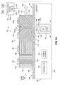
- FIG. 6A is a schematic illustration of a side view of an embodiment of the system 90 for determining and verifying ply orientation 98 (see FIG. 5 ) of the composite laminate 28, where the composite laminate 28 is undergoing a first scan 104.
- the system 90 comprises the composite laminate 28 having a prepared edge 92a that is to be scanned and analyzed with the scanning assembly 100.
- the composite laminate 28 (see FIG. 6A ) is preferably in the form of a sample portion or coupon.
- the composite laminate 28 is positioned on the scanning device 102 of the scanning assembly 100.
- the scanning device 102 (see FIG. 6A ) is preferably a flatbed color scanning device or other suitable scanning device, as discussed above.
- the processing device 150 (see FIG. 6A ) is connected to the scanning device 102 (see FIG. 6A ) via connection element 152 (see FIG. 6A ).
- the scanning device 102 includes a housing 164 that houses the controller 160, the power source 162, such as in the form of a motor, and a movable carrier 176.
- the off-axis inclined light source 106 (see FIG. 6A ), such as in the form of a 45° (forty-five degree) light source 106a (see FIG. 6A ), is shown mounted on the movable carrier 176, along with an image capture assembly 172.
- the movable carrier 176 (see FIG. 6A ) preferably moves up and down the length of the scanning device 102 at a constant rate and is preferably driven by the motor.
- the image capture assembly 172 may include one or more image sensors 174 (see FIG. 6A ) and/or other various components (not shown), such as an optical assembly of reflective mirrors and a lens unit, as known in the art.
- the one or more image sensors 174 may comprise a charge coupled device (CCD) array, a complementary metal-oxide semiconductor (CMOS) type image sensor, a contact image sensor (CIS), or another suitable image sensor.
- CMOS complementary metal-oxide semiconductor
- CIS contact image sensor
- the one or more image sensors 174 preferably contain light-sensitive diodes that convert analog light waves into digital signals and that enable conversion of the light source reflections 124 (see FIG. 6A ) into digital pixel information that is transferred as the first scanned image 116 (see FIG. 5 ) and the second scanned image 128 (see FIG. 5 ) to the processing device 150 (see FIGS. 6A , 6B ).
- the scanning device 102 further comprises a glass plate 166 (see FIG. 6A ).
- the prepared edge 92a of the composite laminate 28, in the form of a sample to be analyzed and scanned, is placed on a top surface 168 of the glass plate 166.
- a lid (not shown) of the scanning device 102 may be closed over the composite laminate 28 or may be left open during scanning of the composite laminate 28.
- FIG. 6A shows the composite laminate 28 with sides 178 and positioned in at a forward direction 202 in the scan direction 120.
- the sides 178 (see FIG. 6A ) of the fibers in the plurality of plies 94 (see FIG. 5 ) reflect more light than the fiber ends.
- the off-axis inclined light source 106 directs light 108 at a first angle 110, such as in the form of a 45° (forty-five degree) angle, to the first area 112 on the prepared edge 92a.
- the light 108 (see FIG. 6A ) illuminating the first area 112 (see FIG. 6A ) reflects back as a light source reflection 124 (see FIG. 6A ).
- the image sensors 174 sense the light source reflection 124 (see FIG. 6A ) and convert the light source reflection 124 (see FIG. 6A ) into digital pixel information that is transferred as the first scanned image 116 (see FIG.
- the first scanned image 116 (see FIG. 5 ) is preferably processed with process software 154 (see FIG. 6A ) and may be stored in storage media 156 (see FIG. 6A ) and/or printed with a printing mechanism 158 (see FIG. 6A ).
- the composite laminate 28 includes plies 134, such as 90° (ninety degree) plies, normal or perpendicular to the cross-section surface 114 of the prepared edge 92a, and also normal or perpendicular to the surface 168 of the glass plate 166.
- the plies 134 such as 90° (ninety degree) plies, exhibited dark reflections 136 when scanned in the first scan 104.
- the composite laminate 28 further includes plies 138, such as 0° (zero degree) plies, parallel to the cross-section surface 114 of the prepared edge 92a, and also parallel to the surface 168 of the glass plate 166.
- the plies 138 such as 0° (zero degree) plies, exhibited bright reflections 140 when scanned in the first scan 104.
- the composite laminate 28 further includes plies 142, such as -45° (minus forty-five degree) plies 142b and 45° (forty-five degree) plies 142a, off-axis to the cross-section surface 114 of the prepared edge 92a, and also off-axis to the surface 168 of the glass plate 166.
- the plies 142b such as -45° (minus forty-five degree) plies, exhibited dark transition reflections 144b when scanned in the first scan 104.
- the plies 142a such as 45° (forty-five degree) plies, exhibited brightest transition reflections 144a when scanned in the first scan 104.
- FIG. 6B is a schematic illustration of a side view of the system 90 for determining and verifying ply orientation 98 (see FIG. 5 ) of the composite laminate 28 of FIG. 6A , where the composite laminate 28 is undergoing a second scan 126.
- the system 90 includes the composite laminate 28 positioned on the scanning device 102 of the scanning assembly 100 of FIG. 6A , and the processing device 150 connected to the scanning device 102 via connection element 152.
- the components of the system 90 in FIG. 6B are identical to FIG. 6A except that the orientation 117 (see FIG. 5 ) of the off-axis inclined light source 106 (see FIG. 6B ) is now rotated in a 180 degree rotation 125a (see FIG.
- the orientation 117 (see FIG. 5 ) of the off-axis inclined light source 106 (see FIG. 5 ) is rotated at a rotation 125 (see FIG. 5 ), such as a 180 degree rotation 125a (see FIG. 5 ), relative to the prepared edge 92a (see FIG. 6B ) of the composite laminate 28 (see FIG. 6B ).
- the off-axis inclined light source 106 such as the 45° (forty-five degree) light source 106a, directs light 108 at a second angle 130, such as in the form of a -45° (minus forty-five degree) angle, to the first area 112 on the prepared edge 92a.
- the light 108 (see FIG. 6B ) illuminating the first area 112 (see FIG. 6B ) reflects back as the light source reflection 124 (see FIG. 6B ).
- the image sensors 174 sense the light source reflection 124 (see FIG. 6B ) and convert the light source reflection 124 (see FIG.
- the second scanned image 128 (see FIG. 5 ) is preferably processed with the process software 154 (see FIG. 6B ) and may be stored in storage media 156 (see FIG. 6B ) and/or printed with the printing mechanism 158 (see FIG. 6B ).
- the composite laminate 28 includes plies 134, such as 90° (ninety degree) plies, normal or perpendicular to the cross-section surface 114 of the prepared edge 92a, and normal or perpendicular to the surface 168 of the glass plate 166.
- the plies 134 such as 90° (ninety degree) plies, exhibited dark reflections 136 when scanned with the second scan 126.
- the composite laminate 28 further includes plies 138, such as 0° (zero degree) plies, parallel to the cross-section surface 114 of the prepared edge 92a, and parallel to the surface 168 of the glass plate 166.
- the plies 138 such as 0° (zero degree) plies, exhibited bright reflections 140 when scanned with the second scan 126.
- the composite laminate 28 further includes plies 142, such as-45° (minus forty-five degree) plies 142b and 45° (forty-five degree) plies 142a, off-axis to the cross-section surface 114 of the prepared edge 92a, and off-axis to the surface 168 of the glass plate 166.
- the plies 142b such as -45° (minus forty-five degree) plies, exhibited brightest transition reflections 144a when scanned with the second scan 126.
- the plies 142a such as 45° (forty-five degree) plies, exhibited dark transition reflections 144b when scanned with the second scan 126.
- both the first scan 104 and the second scan 126 that both 0° (zero degree) plies and 90° (ninety degree) plies parallel to the surface 168 (see FIG. 6A ) of the glass plate 166 (see FIG. 6A ) always appeared bright with streaks and exhibited bright reflections 140 when scanned.
- orientation in a crown direction 198 (see FIG. 8 ) or orientation in a forward direction 202 (see FIGS. 6A-6B , 8 ).
- FIG. 7 is a schematic illustration of side-by-side scanned images 180 of first scanned images 116, such as in the form of first cross-sectional scanned images 116a, taken by first scans 104, and second scanned images 128, such as in the form of second cross-sectional scanned images 128a, taken by second scans 126.
- Both the first scans 104 and the second scans 126 were taken of the prepared edge 92a (see FIGS. 6A-6B ) of the composite laminate 28 (see FIGS. 6A-6B ) obtained using one of the embodiments of the method 66 (see FIG. 4A ), the method 80 (see FIG. 4B ), and the system 90 (see FIG.
- the side-by-side scanned images 180 comprise a first half 182 consisting of the first scanned images 116, and a second half 184 consisting of the second scanned images 128.
- the first scanned images 116 and the second scanned images 128 are divided by a dotted line 186.
- sample coupons of the composite laminate 28 were cut with a mill saw at a longitudinal cut 200 (see FIG. 8 ) at a 0° (zero degree) ply orientation angle 190 (see FIG. 5 ).
- An edge 92 (see FIG. 5 ) of the cut composite laminate 28 (see FIG. 5 ) was prepared by a preparation treatment 93 (see FIG. 5 ) consisting of polishing the edge 92 for about 10 (ten) minutes.
- the first scans 104 and the second scans 126 were taken with cross-section surfaces 114 (see FIG. 5 ) of the composite laminate 28 samples parallel to the scan direction 120 (see FIGS. 5 , 6A ).
- the first scanned images 116 and the second scanned images 128 included scanned images of plies 138, such as 0° (zero degree) plies, parallel to the cross-section surface 114 (see FIGS. 6A-6B ) of the prepared edge 92a (see FIG. 5 ).
- plies 138 such as 0° (zero degree) plies
- both the first scan 104 of the 0° (zero degree) plies and the second scan 126 of the 0° (zero degree) plies exhibited bright reflections 140.
- the first scanned images 116 and the second scanned images 128 included scanned images of plies 134, such as 90° (ninety degree) plies, normal to the cross-section surface 114 (see FIGS. 6A-6B ) of the prepared edge 92a (see FIG. 5 ).
- plies 134 such as 90° (ninety degree) plies
- both the first scan 104 of the 90° (ninety degree) plies and the second scan 126 of the 90° (ninety degree) plies exhibited dark reflections 140.
- the first scanned images 116 and the second scanned images 128 included scanned images of 45° (forty-five degree) plies 142a off-axis to the cross-section surface 114 (see FIGS. 6A-6B ) of the prepared edge 92a (see FIG. 5 ).
- the first scan 104 of the 45° (forty-five degree) plies 142a exhibited brightest reflections 144a
- the second scan 126 of the 45° (forty-five degree) plies exhibited dark reflections 144b.
- the first scanned images 116 and the second scanned images 128 included scanned images of -45° (minus forty-five degree) plies 142b off-axis to the cross-section surface 114 (see FIGS. 6A-6B ) of the prepared edge 92a (see FIG. 5 ).
- the first scan 104 of the -45° (minus forty-five degree) plies 142b exhibited dark reflections 144b
- the second scan 126 of the -45° (minus forty-five degree) plies exhibited brightest reflections 144a.
- FIG. 7 shows the first scanned images 116 and the second scanned images 128 included PW plies 187.
- PW plies 187 comprise a type of woven fabric consisting of a mixture of plies 134, such as 90° (ninety degree) plies, normal to the cross-section surface 114 (see FIGS. 6A-6B ) of the prepared edge 92a (see FIG. 5 ), and plies 138, such as 0° (zero degree) plies, parallel to the cross-section surface 114 (see FIGS. 6A-6B ) of the prepared edge 92a (see FIG. 5 ).
- both the first scan 104 of the PW plies 187 and the second scan 126 of the PW plies 187 exhibited speckled dark/bright mixture reflections 188.
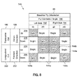
- FIG. 8 is an illustration of an embodiment of the baseline matrix 148 that was used as the ply orientation verification 147 (see FIG. 5 ) for the ply orientations 98 (see FIG. 5 ) of the plurality of plies 94 (see FIG. 5 ) shown in FIG. 7 .
- the baseline matrix 148 as shown in FIG. 8 , was created by using a known composite laminate or known composite laminates, such as composite skins, with known ply orientations, to verify the ply orientation 98 (see FIG. 5 ) determined from the first scans 104 and second scans 126 shown in FIG. 7 .
- the baseline matrix 148 may be modified depending on the baseline ply orientation 99 (see FIG. 8 ) and ply orientation angles 190 (see FIG. 8 ) of the plurality of baseline plies 95 (see FIG. 5 ) that make up the baseline composite laminate 29 (see FIG. 8 ) used as a baseline to verify a composite laminate 28 (see FIG. 5 ).
- the baseline matrix 148 shows the baseline ply orientation 99 having the ply orientation angles 190 of 45° (forty-five degrees) and -45° (minus forty-five degrees).
- the baseline matrix 148 shows the baseline composite laminate 29 (see FIG. 5 ) samples were obtained from the left side 192 and the right side 194 of the aircraft 10 (see FIG. 1 ).
- the baseline matrix 148 shows the baseline composite laminate 29 samples were cut at a transverse cut 196 and a longitudinal cut 200 and were oriented in a crown direction 198, either up 204 of down 206, and were oriented in a forward direction 202, either up 204 of down 206.
- the light source reflections 124 (see FIG. 5 ) of the 45° (forty-five degree) plies exhibited both dark transition reflections 144b and bright transition reflections 144a on the left side 192 and the right side 194.
- the light source reflections 124 (see FIG. 5 ) of the -45° (minus forty-five degree) plies exhibited both bright transition reflections 144a and dark transition reflections 144b on the left side 192 and on the right side 194.
- the baseline matrix 148 shows the differential scanning brightness 132 (see FIG. 5 ) of the each of the +/-45° (plus/minus forty-five degree) plies with the bright/dark transition reflections 144a, 144b.
- the differential scanning brightness 132 may also be used to verify the ply orientation 98 (see FIG. 5 )
- Disclosed embodiments of the method 66 (see FIG. 4A ), the method 80 (see FIG. 4B ), and the system 90 (see FIG. 5 ) provide numerous advantages over known methods and systems, including providing a quick process for determining and verifying the ply orientation 98 (see FIG. 5 ) of composite laminates 28 (see FIG. 5 ) that are cured, so as to maintain uniformity and consistency of the composite laminates 28 (see FIG. 5 ) and to comply with design and/or quality requirements for the composite laminates 28 (see FIG. 5 ).
- disclosed embodiments of the method 66 (see FIG. 4A ), the method 80 (see FIG. 4B ), and the system 90 (see FIG.
- disclosed embodiments of the method 66 involve performing a first scan 104 and a second scan 126 of just the prepared edge 92a the composite material 28 (see FIG. 5 ) to determine the ply orientation 98 (see FIG. 5 ) of the plurality of plies 94 (see FIG. 5 ) which make up the composite laminate 28 (see FIG. 5 ).
- the prepared edge 92a is preferably scanned from two different angles, including a first angle 110 (see FIGS. 5 , 6A ) and a second angle 130 (see FIGS. 5 , 6B ).
- disclosed embodiments of the method 66 do not require extensive polishing of the edge 92 (see FIG. 5 ) of the composite laminate 28 (see FIG. 5 ) prior to scanning, do not require mounting of the composite laminate 28 (see FIG. 5 ) in order to be polished, do not require a plurality of microscopic images be taken and edited together to enable sufficient visibility under a microscope, and do not require labor intensive analysis of each ply to discern the difference between 0° (zero degree) plies and +/-45° (plus/minus forty-five degree) plies.
- disclosed embodiments of the method 66 do not require a second cut be made of the composite laminate 28 (see FIG. 5 ) sample coupon, and do not require a repeat process and analysis of the second cut to sufficiently distinguish between +/-45° (plus/minus forty-five degree) plies to comply with qualification requirements.
- disclosed embodiments of the method 66 (see FIG. 4A ), the method 80 (see FIG. 4B ), and the system 90 (see FIG. 5 ) utilize a 45° (forty-five degree) light source 106a (see FIG. 5 ) from a scanning device 102 (see FIG. 5 ) and images the composite laminate 28 (see FIG. 5 ) oriented transverse to the light source travel path 118 (see FIG. 5 ) twice, with a 180 degree rotation 125a (see FIG. 5 ) between scanning of the first scanned image 116 and scanning of the second scanned image 128.
- the first scanned image 116 (see FIG. 5 ) and the second scanned image 128 see FIG.
- disclosed embodiments of the method 66 (see FIG. 4A ), the method 80 (see FIG. 4B ) and the system 90 (see FIG. 5 ) provide an efficient process where the number of polishing and preparing steps for preparing an edge 92 (see FIG. 5 ) prior to scanning may be reduced and a lower polish finish may be obtained from a typical 240 grit sandpaper with a 0.05 *m (micron) finish to a 600 grit sandpaper with a 0.06 *m (micron) finish, as the shape of the fiber at the cross-section is no longer being interrogated. Rather, the light source reflections 124 (see FIG. 5 ) from two opposite angled off-axis inclined light source scans or passes may be used.
- a scanning device 102 with a 45° (forty-five degree) light source 106a (see FIG. 5 ) may be used to image the entire thickness of the composite laminate 28 (see FIG. 5 ).
- the scanning device 102 has two off-axis inclined light sources 106 (see FIG. 5 )
- a layer of tape may be placed over one off-axis inclined light source 106 (see FIG. 5 )
- the scanning device 102 may be used to image the entire thickness of the composite laminate 28 (see FIG. 5 ).
- Multiple composite laminates 28 may be imaged simultaneously, and may be constrained only by the size of the scanning device 102 (see FIG. 5 ).
- disclosed embodiments of the method 66 may be polished much faster than the polishing procedures required with known methods and systems, may require only one single cut of the composite laminate 28 sample rather than two, may not require mounting in order to be polished, may not require composite imaging, and may significantly reduce the difficulty of visual methods of ply orientation determination.
Landscapes
- Engineering & Computer Science (AREA)
- Textile Engineering (AREA)
- Life Sciences & Earth Sciences (AREA)
- Chemical & Material Sciences (AREA)
- General Physics & Mathematics (AREA)
- Physics & Mathematics (AREA)
- Biochemistry (AREA)
- Analytical Chemistry (AREA)
- Health & Medical Sciences (AREA)
- General Health & Medical Sciences (AREA)
- Immunology (AREA)
- Pathology (AREA)
- Wood Science & Technology (AREA)
- Composite Materials (AREA)
- Mechanical Engineering (AREA)
- Computer Vision & Pattern Recognition (AREA)
- Signal Processing (AREA)
- Length Measuring Devices By Optical Means (AREA)
- Investigating Or Analysing Materials By Optical Means (AREA)
Abstract
Description
- The disclosure relates generally to methods and systems for analyzing composite structures, and more particularly, to methods and systems for determining and verifying ply orientation of composite laminates used in composite structures, such as aircraft composite structures.
- Composite structures may be used in a wide variety of applications, including in the manufacture of aircraft, spacecraft, rotorcraft, watercraft, automobiles, and other vehicles and structures, due to their high strength-to-weight ratios, corrosion resistance and other favorable properties. In particular, in aircraft construction, composite structures may be used to form the tail sections, wings, fuselage and other component parts of the aircraft.
- Composite laminates used to form composite structures may be manufactured by laying up or stacking multiple layers or "plies" together and curing the lay-up. A single layer or ply typically consists of reinforcing fibers in a matrix material. The composite laminates may be stacked with plies of different ply orientations in a defined sequence per design and/or quality requirements to optimize performance, such as load-carrying capacity. For example, the ply orientations may typically include 0° (zero degree) ply orientation, 90° (ninety degree) ply orientation, +45° (plus forty-five degree) / -45° (minus forty-five degree) ply orientation, or another suitable ply orientation. Determining the ply orientation of the composite laminates is important in optimizing composite laminate designs, as well as in complying with composite laminate design and/or quality requirements.
- In addition, during the composite laminate manufacturing process, inconsistencies may occur during the lay-up or stacking of the plies, such as, for example, misoriented plies, gaps, overlaps, or other inconsistencies. Methods and systems for determining and verifying ply orientation may be used to analyze the composite laminates for any possible inconsistencies and to ensure that the composite laminates manufactured by the lay-up or stacking process meet the design and/or quality requirements pertaining to ply orientation.
- Known methods and systems for determining and verifying ply orientation exist. However, such known methods and systems may require an extensive and time consuming polishing process of an edge or portion of a sample composite laminate to be analyzed. Such polishing process may be needed to obtain sufficient visibility of the fiber orientation of the composite laminate plies. The polishing process may require mounting the sample in an epoxy resin material, or a similar material, so that the sample may be secured in place during the polishing process. Such mounting process may be difficult with large samples that require polishing.
- Further, such known methods and systems for determining and verifying ply orientation may require the use of a high magnification microscope, i.e., 100x or greater, to observe the individual fibers of the composite laminate plies of the sample. If the sample to be analyzed is larger than the field of view of the microscope, this may require obtaining multiple images of the composite laminate plies and editing the images together with a known photo editing software to obtain a continuous view of the sample under the microscope. This image preparation process may be time consuming and labor intensive.
- Moreover, such known methods and systems for determining and verifying ply orientation may require additional cutting, polishing, and image processing steps to analyze fibers of the sample composite laminate having a +45° (plus forty-five degree) ply orientation and a -45° (minus forty-five degree) ply orientation. To sufficiently distinguish between a +45° (plus forty-five degree) ply orientation and a -45° (minus forty-five degree) ply orientation, a second cut of the sample composite laminate may need to be made and the processes of mounting, polishing, and image processing may need to be performed for both cuts of the +45° (plus forty-five degree) ply orientation and the -45° (minus forty-five degree) ply orientation. The additional work needed to analyze +/-45° (plus/minus forty-five degree) plies may increase the overall time and costs of manufacturing.
- Thus, such known methods and systems for determining and verifying ply orientation may be very time consuming, labor intensive, and tedious, and may, in turn, result in increased manufacturing time and costs. For example, a known process for determining and verifying ply orientation that includes mounting, polishing, and image processing steps may take several days to complete.
- Accordingly, there is a need in the art for an improved method and system for determining and verifying ply orientation of a composite laminate that provide advantages over known methods and systems.
- Example implementations of the present disclosure provide an improved method and system for determining and verifying ply orientation of a composite laminate to overcome the laborious nature of existing solutions. As discussed in the below detailed description, embodiments of the improved method and system for determining and verifying ply orientation of a composite laminate may provide significant advantages over existing methods and systems.
- In an embodiment of the disclosure, there is provided a method for determining and verifying ply orientation of a composite laminate. The method comprises the step of performing a first scan of a prepared edge of the composite laminate using an off-axis inclined light source directing light at a first angle to a first area on the prepared edge to produce a first scanned image. The method further comprises the step of rotating an orientation of the off-axis inclined light source relative to the prepared edge. The method further comprises the step of performing a second scan of the prepared edge using the off-axis inclined light source directing light at a second angle to the first area on the prepared edge to produce a second scanned image.
- The method further comprises the step of comparing the first scanned image and the second scanned image to determine a ply orientation of each ply of the composite laminate. The ply orientation is preferably determined based on light source reflections of the off-axis inclined light source. Preferably, the steps of performing the first scan of the prepared edge and performing the second scan of the prepared edge comprise using a scanning device having an optical resolution of 1200 dpi (dots per inch) or greater. More preferably, the step of comparing the first scanned image and the second scanned image to determine the ply orientation comprises using a manual visual comparison of the light source reflections of the first scanned image and the second scanned image. The method further comprises the step of verifying the ply orientation of the composite laminate against a baseline ply orientation of a baseline composite laminate. Preferably, the step of verifying the ply orientation of the composite laminate comprises verifying that a plurality of plies of the composite laminate are laid up correctly as intended by design.
- In another embodiment of the disclosure, there is provided a method for determining and verifying ply orientation of a composite laminate of an aircraft composite structure. The method comprises the step of preparing an edge of the composite laminate to obtain a prepared edge. The method further comprises the step of performing with a scanning device having at least one off-axis inclined light source a first scan of the prepared edge using the at least one off-axis inclined light source to direct light at a first angle to a first area on the prepared edge to produce a first scanned image. The method further comprises the step of rotating 180 degrees an orientation of the at least one off-axis inclined light source relative to the prepared edge, such that the off-axis inclined light source directs light at a second acute angle symmetrically opposite the first acute angle. The method further comprises the step of performing with the scanning device a second scan of the prepared edge using the at least one off-axis inclined light source to direct light at the symmetrically opposite second acute angle to the first area on the prepared edge to produce a second scanned image.
- The method further comprises the step of transferring the first scanned image and the second scanned image from the scanning device to a processing device for processing. The method further comprises the step of comparing the first scanned image and the second scanned image to determine a ply orientation of each ply of the composite laminate. Preferably, the step of comparing the first scanned image and the second scanned image to determine the ply orientation comprises using at least one of a manual visual comparison and an automated comparison with a process software, of the light source reflections of the first scanned image and the second scanned image.The ply orientation is preferably determined based on light source reflections of the at least one off-axis inclined light source. Preferably, the steps of performing the first scan (104) of the prepared edge (92a) and performing the second scan (126) of the prepared edge (92a) comprise performing with the scanning device (102) having a 45° (forty-five degree) light source (106a) and an optical resolution (122) of 1200 dpi (dots per inch) or greater. The method further comprises the step of preparing a baseline matrix comprising a baseline ply orientation of a baseline composite laminate of the aircraft composite structure. The method further comprises the step of verifying the ply orientation of the composite laminate against the baseline ply orientation of the baseline matrix. Preferably, the step of comparing the first scanned image and the second scanned image to determine the ply orientation comprises determining the ply orientation based on light source reflections comprising bright/dark transition reflections in +/- 45° (plus/minus forty-five) degree plies to a cross-section surface of the prepared edge, dark reflections for plies normal to the cross-section surface of the prepared edge, and bright reflections for plies parallel to the cross-section surface of the prepared edge.
- In another embodiment of the disclosure, there is provided a system for determining and verifying ply orientation of a composite laminate. The system comprises a composite laminate that is cured and comprises at least one prepared edge and a plurality of plies, each ply having a ply orientation.
- The system further comprises a scanning assembly. The scanning assembly comprises a scanning device having at least one off-axis inclined light source configured to direct light at a first angle to a first area on the prepared edge of the composite laminate to illuminate and capture a first scanned image. The at least one off-axis inclined light source is further configured to direct light at a second angle to the first area on the prepared edge to illuminate and capture a second scanned image. The scanning assembly further comprises a processing device coupled to the scanning device. The processing device is configured to receive and process the first scanned image and the second scanned image from the scanning device. Preferably, the composite laminate is a fiber-reinforced composite laminate comprised of continuous fibers, and the scanning device has an optical resolution of 1200 dpi (dots per inch) or greater. The scanning assembly further comprises a baseline matrix comprising a baseline ply orientation of a baseline composite laminate.
- The system provides a ply orientation determination of each ply of the composite laminate based on light source reflections of the at least one off-axis inclined light source and a comparison of the first scanned image and the second scanned image. The system further provides a ply orientation verification of the composite laminate using the baseline matrix. Preferably, the processing device comprises a computer having process software to process the first scanned image and the second scanned image to enable comparison of the first scanned image and the second scanned image against each other and against the baseline matrix.
- The features, functions, and advantages that have been discussed can be achieved independently in various embodiments of the disclosure or may be combined in yet other embodiments further details of which can be seen with reference to the following description and drawings.
- The disclosure can be better understood with reference to the following detailed description taken in conjunction with the accompanying drawings which illustrate preferred and exemplary embodiments, but which are not necessarily drawn to scale, wherein:
-
FIG. 1 is an illustration of a perspective view of an aircraft having one or more composite structures that may be scanned and verified using embodiments of a method and a system of the disclosure; -
FIG. 2 is an illustration of a flow diagram of an embodiment of an aircraft manufacturing and service method; -
FIG. 3 is an illustration of a functional block diagram of an embodiment of an aircraft -
FIG. 4A is an illustration of a flow diagram of one of the embodiments of a method for determining and verifying ply orientation of a composite laminate of the disclosure; -
FIG. 4B is an illustration of a flow diagram of one of the embodiments of a method for determining and verifying ply orientation of a composite laminate of an aircraft composite structure of the disclosure; -
FIG. 5 is an illustration of a functional block diagram of an embodiment of a system for determining and verifying ply orientation of a composite laminate of the disclosure; -
FIG. 6A is a schematic illustration of a side view of an embodiment of a system for determining and verifying ply orientation of a composite laminate, where the composite laminate is undergoing a first scan; -
FIG. 6B is a schematic illustration of a side view of the system for determining and verifying ply orientation of the composite laminate ofFIG. 6A , where the composite laminate is undergoing a second scan; -
FIG. 7 is a schematic illustration of side-by-side scanned images of first scanned images taken by first scans and second scanned images taken by second scans of a prepared edge of a composite laminate obtained using one of the embodiments of a method and a system of the disclosure; and, -
FIG. 8 is an illustration of an embodiment of a baseline matrix that may be used in one of the embodiments of a method and a system for determining and verifying ply orientation of the composite laminate of the disclosure. - Disclosed embodiments will now be described more fully hereinafter with reference to the accompanying drawings, in which some, but not all of the disclosed embodiments are shown. Indeed, several different embodiments may be provided and should not be construed as limited to the embodiments set forth herein. Rather, these embodiments are provided so that this disclosure will be thorough and will fully convey the scope of the disclosure to those skilled in the art.
- Now referring to the Figures,
FIG. 1 is an illustration of a perspective view of anaircraft 10 having one or morecomposite structures 12. As further shown inFIG. 1 , theaircraft 10 comprises afuselage 14, anose 16,wings 18,engines 20, and anempennage 22 comprisinghorizontal stabilizers 24 and avertical stabilizer 26. As further shown inFIG. 1 , the one or morecomposite structures 12 may comprise acomposite laminate 28. Preferably, the composite laminate 28 (seeFIG. 1 ), discussed in further detail below, is cured and is in the form of a fiber-reinforcedcomposite laminate 28a (seeFIG. 1 ). - Embodiments of the disclosure, discussed in detail below, provide a method 66 (see
FIG. 4A ) for determining and verifying ply orientation of the composite laminate 28 (seeFIGS. 1 ,5 ), provide a method 80 (seeFIG. 4B ) for determining and verifying ply orientation of thecomposite laminate 28 of the aircraftcomposite structure 12, and provide a system 90 (seeFIG. 5 ) for determining and verifying ply orientation of the composite laminate 28 (seeFIGS. 1 ,5 ). -
FIG. 2 is an illustration of a flow diagram of an embodiment of an aircraft manufacturing andservice method 30.FIG. 3 is an illustration of a functional block diagram of an embodiment of anaircraft 50. Referring toFIGS. 2-3 , embodiments of the disclosure may be described in the context of the aircraft manufacturing andservice method 30, as shown inFIG. 2 , and theaircraft 50, as shown inFIG. 3 . During pre-production, the exemplary aircraft manufacturing and service method 30 (seeFIG. 2 ) may include specification and design 32 (seeFIG. 2 ) of the aircraft 50 (seeFIG. 3 ) and material procurement 34 (seeFIG. 2 ). During manufacturing, component and subassembly manufacturing 36 (seeFIG. 2 ) and system integration 38 (seeFIG. 2 ) of the aircraft 50 (seeFIG. 3 ) takes place. Thereafter, the aircraft 50 (seeFIG. 3 ) may go through certification and delivery 40 (seeFIG. 2 ) in order to be placed in service 42 (seeFIG. 2 ). While in service 42 (seeFIG. 2 ) by a customer, the aircraft 50 (seeFIG. 3 ) may be scheduled for routine maintenance and service 44 (seeFIG. 2 ), which may also include modification, reconfiguration, refurbishment, and other suitable services. - Each of the processes of the aircraft manufacturing and service method 30 (see
FIG. 2 ) may be performed or carried out by a system integrator, a third party, and/or an operator (e.g., a customer). For the purposes of this description, a system integrator may include, without limitation, any number of aircraft manufacturers and major-system subcontractors; a third party may include, without limitation, any number of vendors, subcontractors, and suppliers; and an operator may include an airline, leasing company, military entity, service organization, and other suitable operators. - As shown in
FIG. 3 , theaircraft 50 produced by the exemplary aircraft manufacturing andservice method 30 may include anairframe 52 with a plurality ofsystems 54 and an interior 56. As further shown inFIG. 3 , examples of thesystems 54 may include one or more of apropulsion system 58, anelectrical system 60, ahydraulic system 62, and anenvironmental system 64. Any number of other systems may be included. Although an aerospace example is shown, the principles of the disclosure may be applied to other industries, such as the automotive industry. - Methods and systems embodied herein may be employed during any one or more of the stages of the aircraft manufacturing and service method 30 (see
FIG. 2 ). For example, components or subassemblies corresponding to component and subassembly manufacturing 36 (seeFIG. 2 ) may be fabricated or manufactured in a manner similar to components or subassemblies produced while the aircraft 50 (seeFIG. 3 ) is in service 42 (seeFIG. 2 ). Also, one or more apparatus embodiments, method embodiments, or a combination thereof, may be utilized during component and subassembly manufacturing 36 (seeFIG. 2 ) and system integration 38 (seeFIG. 2 ), for example, by substantially expediting assembly of or reducing the cost of the aircraft 50 (seeFIG. 3 ). Similarly, one or more of apparatus embodiments, method embodiments, or a combination thereof, may be utilized while the aircraft 50 (seeFIG. 3 ) is in service 42 (seeFIG. 2 ), for example and without limitation, to maintenance and service 44 (seeFIG. 2 ). - Referring to
FIG. 4A , in an embodiment of the disclosure, there is provided amethod 66 for determining and verifying a ply orientation 98 (seeFIG. 5 ) of the composite laminate 28 (seeFIGS. 1 ,5 ).FIG. 4A is an illustration of a flow diagram of one of the embodiments of themethod 66 for determining and verifying ply orientation 98 (seeFIG. 5 ) of the composite laminate 28 (seeFIG. 5 ). - Referring to
FIG. 4B , in another embodiment of the disclosure, there is provided amethod 80 for determining and verifying ply orientation 98 (seeFIG. 5 ) of the composite laminate 28 (seeFIGS. 1 ,5 ) of the aircraft composite structure 12 (seeFIGS. 1 ,5 ).FIG. 4B is an illustration of a flow diagram of one of the embodiments of themethod 80 for determining and verifying ply orientation 98 (seeFIG. 5 ) of the composite laminate 28 (seeFIG. 5 ) of the aircraft composite structure 12 (seeFIGS. 1 ,5 ). - Referring to
FIG. 5 , in another embodiment of the disclosure, there is provided asystem 90 for determining and verifying ply orientation 98 of thecomposite laminate 28.FIG. 5 is an illustration of a functional block diagram of an embodiment of thesystem 90 for determining and verifying ply orientation 98 of thecomposite laminate 28. - In the below discussion of the
method 66 shown inFIG. 4A , reference will be made to various components of therelated system 90 ofFIG. 5 . Similarly, in the below discussion of themethod 80 shown inFIG. 4B , reference will be made to the various components of therelated system 90 ofFIG. 5 . - As shown in
FIG. 4A , themethod 66 comprisesoptional step 68 of preparing an edge 92 (seeFIG. 5 ) of the composite laminate 28 (seeFIG. 5 ) to obtain aprepared edge 92a (seeFIG. 5 ). During manufacture of the composite laminate 28 (seeFIG. 5 ), one or more edges 92 (seeFIG. 5 ) of the composite laminate 28 (seeFIG. 5 ) may become rough and may require one or more preparation treatments 93 (seeFIG. 5 ), in order to obtain aprepared edge 92a (seeFIG. 5 ) that is smooth or polished prior to undergoing the scanning steps of the method 66 (seeFIG. 4A ), discussed below. Preferably, the preparation treatments 93 (seeFIG. 5 ) comprise one or more procedures, such as smoothing, polishing, abrading, finishing, cleaning, or another suitable preparation treatment of theedge 92a (seeFIG. 5 ) of the composite laminate 28 (seeFIG. 5 ). The preparation treatments 93 (seeFIG. 5 ) may be performed via a manual process, for example, manually by rubbing the edge 92 (seeFIG. 5 ) with sandpaper or another abrading device, with a polishing or cleaning solution or device, or with another suitable manual preparation treatment. Alternatively, the preparation treatments 93 (seeFIG. 5 ) may be performed via an automated process, or via a combination of manual and automated processes. - The
step 68 of preparing the edge 92 (seeFIG. 5 ) may be performed in a short period of time, and preferably, in about ten (10) minutes to thirty (30) minutes, and more preferably, in about ten (10) minutes. This short preparation treatment time for preparing the edge 92 (seeFIG. 5 ) is advantageous, as compared to the mounting and polishing processes required in known methods for determining and verifying ply orientation, which may take hours or days to complete. - The composite laminate 28 (see
FIGS. 1 ,5 ) is preferably in the form of a fiber-reinforcedcomposite laminate 28a (seeFIGS. 1 ,5 ) comprised of a plurality of plies 94 (seeFIG. 5 ). Preparing the edge 92 (seeFIG. 5 ) of the composite laminate 28 (seeFIGS. 1 ,5 ) to obtain theprepared edge 92a (seeFIG. 5 ) preferably facilitates visibility of the plurality of plies 94 (seeFIG. 5 ) at theprepared edge 92a (seeFIG. 5 ), in scanned images of theprepared edge 92a, after theprepared edge 92a has been scanned, as discussed below. - The plurality of plies 94 (see
FIG. 5 ) preferably comprise continuous fibers 96 (seeFIG. 5 ) in a resin matrix material 97 (seeFIG. 5 ). Continuous fibers 96 (seeFIG. 5 ) are preferred over discontinuous or chopped fibers. With continuous fibers 96 (seeFIG. 5 ), there may be few, if any, breaks in the reinforcements, and continuous fibers 96 may provide improved performance properties of the composite laminate 28 (seeFIG. 5 ). - The continuous fibers 96 (see
FIG. 5 ) comprising the plurality of plies 94 (seeFIG. 5 ) preferably comprise reinforcement or high-strength fibers made of one or more materials, such as carbon, glass, fiberglass, graphite, boron, aromatic polyamide, silicon carbide, or another suitable reinforcement or high-strength material. The resin matrix material 97 (seeFIG. 5 ) may comprise polymeric, ceramic, metallic or other matrix materials, such as epoxy, polyester, vinyl ester resins, polyetheretherketone polymer (PEEK), polyetherketoneketone polymer (PEKK), polyimides, bismaleimide, aluminum, titanium, alumina, or another suitable matrix material. As used herein, "cured" means undergoing a full or partial hardening process, with or without heat, for example, the resin matrix material hardening to form a strong, rigid, fiber-reinforced composite laminate. - The plurality of plies 94 (see
FIG. 5 ) of the composite laminate 28 (seeFIGS. 1 ,5 ) may comprise a prepreg unidirectional tape, a unidirectional fiber tape, a carbon fiber-reinforced plastic (CFRP) tape, or another suitable tape; a carbon fiber-reinforced plastic (CFRP) fabric, a prepreg fabric, a woven fabric including a woven carbon fiber fabric, or another suitable fabric; a combination of a tape or a fabric thereof; or another suitable composite material. - The composite laminate 28 (see
FIG. 5 ) may be formed of a composite material by any suitable means including, but not limited to, hand lay up, automated lay up, or another suitable forming process. Each ply 94 (seeFIG. 5 ) preferably has a ply orientation 98 (seeFIG. 5 ). The ply orientation 98 (seeFIG. 5 ) may be tailored to any ply direction desired. For example, the ply orientation 98 (seeFIG. 5 ) may include, without limitation, such ply orientations as: 0° (zero degree) ply orientation, where a ply orientation angle 190 (seeFIG. 5 ) of the fiber is 0° (zero degrees) or parallel to a cross-section surface 114 (seeFIGS. 5 ,6A ) of theprepared edge 92a (seeFIGS. 5 ,6A ); 90° (ninety degree) ply orientation, where the ply orientation angle 190 (seeFIG. 5 ) of the fiber is 90° (ninety degrees) or perpendicular or normal to the cross-section surface 114 (seeFIGS. 5 ,6A ) of theprepared edge 92a (seeFIGS. 5 ,6A ); +45° (plus forty-five degree) / -45° (minus forty-five degree) ply orientation, where the ply orientation angle 190 (seeFIG. 5 ) of the fiber is +45° (plus forty-five degrees) / -45° (minus forty-five degrees) to the cross-section surface 114 (seeFIGS. 5 ,6A ) of theprepared edge 92a (seeFIG. 5 ), or another suitable ply orientation. - As used herein, "ply orientation angle" means the angle that the fibers of a ply make with a cross-section surface of a prepared edge of a composite laminate, or alternatively, the angle that the fibers of a ply make with a surface of a scanning device that a sample of the composite laminate is positioned on for image scanning. Further, by way of example, as used herein, "+45° (plus forty-five degrees)" means that a ply is rotated 45° (forty-five degrees) clockwise relative to the orientation of an adjacent ply layer and "-45° (minus forty-five degrees)" means that a ply is rotated 45° (forty-five degrees) counterclockwise relative to the orientation of an adjacent ply layer.
- As shown in
FIG. 4A , themethod 66 further comprisesstep 70 of performing a first scan 104 (seeFIGS. 5 ,6A ) of theprepared edge 92a (seeFIG. 5 ) of the composite laminate 28 (seeFIG. 5 ). The first scan 104 (seeFIG. 5 ) is preferably performed using an off-axis inclined light source 106 (i.e., a light source that is not perpendicular to theprepared edge 92a as shown inFIG. 5 ). The off-axis inclined light source 106 (seeFIG. 5 ) preferably directs light 108 (seeFIG. 5 ) at a firstacute angle 110 relative to theprepared edge 92a (i.e., an angle that is not perpendicular to the prepared surface as shown inFIG. 5 ), to direct light 108 to a first area 112 (seeFIG. 5 ) on theprepared edge 92a (seeFIG. 5 ) to produce a first scanned image 116 (seeFIG. 5 ). The off-axis inclined light source 106 (seeFIG. 5 ) illuminates the first area 112 (seeFIG. 5 ) on theprepared edge 92a (seeFIG. 5 ). - As shown in
FIG. 4A , themethod 66 further comprisesstep 72 of rotating an orientation 117 (seeFIG. 5 ) of the off-axis inclined light source 106 (seeFIG. 5 ) at a rotation 125 (seeFIG. 5 ) relative to theprepared edge 92a (seeFIG. 5 ) of the composite laminate 28 (seeFIG. 5 ). Thestep 72 of rotating the orientation 117 (seeFIG. 5 ) of the off-axis inclined light source 106 (seeFIG. 5 ) preferably comprises rotating the orientation 117 (seeFIG. 5 ) of the off-axis inclinedlight source 106 in a 180degree rotation 125a (seeFIG. 5 ) relative to theprepared edge 92a (seeFIG. 5 ) of the composite laminate 28 (seeFIG. 5 ). - As shown in
FIG. 4A , themethod 66 further comprisesstep 74 of performing a second scan 126 (seeFIG. 5 ) of theprepared edge 92a (seeFIG. 5 ) of the composite laminate 28 (seeFIG. 5 ). The second scan 126 (seeFIG. 5 ) is preferably performed with the orientation of the off-axis inclined light source 106 (seeFIG. 5 ) rotated 180 degrees from that of the first scan. With the orientation of the off-axis inclined light source rotated 180 degrees relative that of the first scan, the off-axis inclined light source 106 (seeFIG. 5 ) preferably directs light 108 (seeFIG. 5 ) at a secondacute angle 130 relative to theprepared edge 92a that is symmetrically opposite the first acute angle 110 (seeFIG. 5 ), to direct light at a symmetrically opposite secondacute angle 110 to the first area 112 (seeFIG. 5 ) on theprepared edge 92a to produce a second scanned image 128 (seeFIG. 5 ). - The step 70 (see
FIG. 4A ) of performing the first scan 104 (seeFIG. 5 ) of theprepared edge 92a (seeFIG. 5 ) and the step 74 (seeFIG. 4A ) of performing the second scan 126 (seeFIG. 5 ) of theprepared edge 92a (seeFIG. 5 ) preferably comprise using a scanning device 102 (seeFIG. 5 ) having alight source 106a (seeFIG. 5 ) oriented at an angle of 45° (forty-five degree) relative to the prepared surface, such that light directed at the firstacute angle 110 is about 45° (forty-five degree) relative to the prepared surface and light directed at the secondacute angle 130 is about 45° (forty-five degree) relative to the prepared surface and symmetrically opposite the firstacute angle 110. - The scanning device 102 (see
FIG. 5 ) is preferably a flatbed color image scanning device or another suitable scanning device. The scanning device 102 (seeFIG. 5 ) preferably has one or more off-axis inclined light sources 106 (seeFIG. 5 ) housed within a housing 164 (seeFIG. 6A ) of the scanning device 102 (seeFIG. 6A ). The off-axis inclined light source 106 (seeFIG. 5 ) may comprise a fluorescent light source, such as a fluorescent lamp or a cold cathode fluorescent lamp; a xenon light source, such as a xenon lamp; LED (light-emitting diode) lights, or another suitable light source. The off-axis inclined light source 106 (seeFIG. 5 ) may be connected to a voltage regulator (not shown) to ensure consistency of light over the scan pass. - The scanning device 102 (see
FIG. 5 ) may preferably have one off-axis inclined light source 106 (seeFIG. 5 ). Alternatively, the scanning device 102 (seeFIG. 5 ) may have more than one off-axis inclined light source 106 (seeFIG. 5 ), such as two off-axis inclined light sources 106 (seeFIG. 5 ). For example, for scanning of the composite laminate 28 (seeFIG. 5 ) with the scanning device 102 (seeFIG. 5 ) having two off-axis inclined light sources 106 (seeFIG. 5 ), the off-axis inclined light sources 106 (seeFIG. 5 ) may be controlled so that a first off-axis inclined light source is turned on and a second off-axis inclined light source is turned off during the first scan 104 (seeFIG. 5 ). Then, with the second scan 126 (seeFIG. 5 ), the first off-axis inclined light source is turned off and the second off-axis inclined light source is turned on. - In one embodiment, during the
first scan 104, the off-axis inclinedlight source 106 may direct light 108, for example, at a +45° (plus forty-five degree) angle to the first area 112 (seeFIG. 5 ) on theprepared edge 92a (seeFIG. 5 ). The orientation 117 (seeFIG. 5 ) of the off-axis inclined light source 106 (seeFIG. 5 ) may then be rotated preferably in a 180degree rotation 125a (seeFIG. 5 ) relative to theprepared edge 92a (seeFIG. 5 ) of the composite laminate 28 (seeFIG. 5 ). Then, during the second scan 126 (seeFIG. 5 ), the off-axis inclined light source 106 (seeFIG. 5 ) may direct light 108 (seeFIG. 5 ), for example, at a -45° (minus forty-five degree) angle to the first area 112 (seeFIG. 5 ) on theprepared edge 92a (seeFIG. 5 ). - Alternatively, during the
first scan 104, the off-axis inclinedlight source 106 may direct light 108, for example, at a +45° (plus forty-five degree) angle to the first area 112 (seeFIG. 5 ) on theprepared edge 92a (seeFIG. 5 ). Then, the composite laminate 28 (seeFIG. 5 ) may be physically rotated 180 degrees and scanned, such that during the second scan 126 (seeFIG. 5 ), the off-axis inclined light source 106 (seeFIG. 5 ) directs light 108 (seeFIG. 5 ), for example, at a -45° (minus forty-five degree) angle to the first area 112 (seeFIG. 5 ) on theprepared edge 92a (seeFIG. 5 ). By rotating the composite laminate 28 (seeFIG. 5 ) 180 degrees and then scanning, the orientation 117 (seeFIG. 5 ) of the off-axis inclined light source 106 (seeFIG. 5 ) is effectively also rotated 180 degrees relative to theprepared edge 92a (seeFIG. 5 ) of the composite laminate 28 (seeFIG. 5 ). - The step 70 (see
FIG. 4A ) of performing the first scan 104 (seeFIG. 5 ) of theprepared edge 92a (seeFIG. 5 ) and the step 74 (seeFIG. 4A ) of performing the second scan 126 (seeFIG. 5 ) of theprepared edge 92a (seeFIG. 5 ) preferably comprise using the scanning device 102 (seeFIG. 5 ) having an optical resolution 122 (seeFIG. 5 ) of 1200 dpi (dots per inch), or greater. The scanning device 102 (seeFIG. 5 ) preferably has a hardware resolution of 1200 x 1200 dpi, or greater; a maximum resolution of 9600 x 9600 dpi, or greater; a scanning speed of 1.6 msec/line (milliseconds per line), or greater, for a black and white scan at 1200 dpi; and a scanning speed of 4.9 msec/line (milliseconds per line), or greater, for a color scan at 1200 dpi. However, the scanning device 102 (seeFIG. 5 ) may have other suitable resolutions and speeds. - An example of a scanning device that may be used with the method 66 (see
FIG. 4A ), the method 80 (seeFIG. 4B ), and the system 90 (seeFIG. 5 ) disclosed herein, includes, but is not limited to, an EPSON flatbed scanning device from Epson America, Inc. of Long Beach, California. (EPSON is a registered trademark of Seiko Epson Kabushiki Kaisha DBA Seiko Epson Corporation of Tokyo, Japan.) However, other suitable scanning devices may also be used. - As shown in
FIG. 4A , themethod 66 further comprisesstep 76 of comparing the first scanned image 116 (seeFIG. 5 ) and the second scanned image 128 (seeFIG. 5 ) to determine the ply orientation 98 (seeFIG. 5 ) of each ply 94 (seeFIG. 5 ) of the composite laminate 28 (seeFIG. 5 ). The ply orientation 98 (seeFIG. 5 ) is preferably determined based on light source reflections 124 (seeFIG. 5 ) of the off-axis inclined light source 106 (seeFIG. 5 ). - In one embodiment, the step 76 (see
FIG. 4A ) of comparing the first scanned image 116 (seeFIG. 5 ) and the second scanned image 128 (seeFIG. 5 ) to determine the ply orientation 98 (seeFIG. 5 ) comprises a manualvisual comparison 146a (seeFIG. 5 ) of the light source reflections 124 (seeFIG. 5 ) of the first scanned image 116 (seeFIG. 5 ) and the second scanned image 128 (seeFIG. 5 ). Preferably, the manualvisual comparison 146a is performed by one or more operators of the method 66 (seeFIG. 4A ). - In another embodiment, the step 76 (see
FIG. 4A ) of comparing the first scanned image 116 (seeFIG. 5 ) and the second scanned image 128 (seeFIG. 5 ) to determine the ply orientation 98 (seeFIG. 5 ) comprises using anautomated comparison 146b (seeFIG. 5 ) with a process software 154 (seeFIG. 5 ) to compare the light source reflections 124 (seeFIG. 5 ) of the first scanned image 116 (seeFIG. 5 ) and the second scanned image 128 (seeFIG. 5 ). In yet another embodiment, the step 76 (seeFIG. 4A ) of comparing the first scanned image 116 (seeFIG. 5 ) and the second scanned image 128 (seeFIG. 5 ) to determine the ply orientation 98 (seeFIG. 5 ) may comprise using a combination of the manualvisual comparison 146a (seeFIG. 5 ) and theautomated comparison 146b (seeFIG. 5 ) with the process software 154 (seeFIG. 5 ). - The step 76 (see
FIG. 4A ) of comparing the first scanned image (seeFIG. 5 ) and the second scanned image 128 (seeFIG. 5 ) to determine the ply orientation 98 (seeFIG. 5 ) preferably comprises determining the ply orientation 98 (seeFIG. 5 ) based on light source reflections 124 (seeFIG. 5 ). Preferably, the light source reflections 124 (seeFIG. 5 ) comprise bright/dark transition reflections FIG. 5 ) in plies 142 (seeFIG. 5 ) off-axis to the cross-section surface 114 (seeFIG. 5 ) of theprepared edge 92a (seeFIG. 5 ), such as +/- 45° (plus/minus forty-five degree) plies 142a, 142b (seeFIG. 5 ) to the cross-section surface 114 (seeFIG. 5 ) of theprepared edge 92a (seeFIG. 5 ). Preferably, the light source reflections 124 (seeFIG. 5 ) further comprise dark reflections 136 (seeFIG. 5 ) for plies 134 (seeFIG. 5 ) normal or perpendicular to the cross-section surface 114 (seeFIG. 5 ) of theprepared edge 92a (seeFIG. 5 ), such as 90° (ninety degree) plies. Preferably, the light source reflections 124 (seeFIG. 5 ) further comprise bright reflections 140 (seeFIG. 5 ) for plies 138 (seeFIG. 5 ) parallel to the cross-section surface 114 (seeFIG. 5 ) of theprepared edge 92a (seeFIG. 5 ), such as 0° (zero degree) plies. - As shown in
FIG. 4A , themethod 66 further comprisesstep 78 of verifying the ply orientation 98 (seeFIG. 5 ) of the composite laminate 28 (seeFIG. 5 ) against one or more baseline ply orientations 99 (seeFIG. 5 ) of a baseline composite laminate 29 (seeFIG. 5 ), and preferably against baseline ply orientations 99 (seeFIG. 5 ) of a plurality of baseline plies 95 (seeFIG. 5 ) of the baseline composite laminate 29 (seeFIG. 5 ). The step 78 (seeFIG. 4A ) of verifying the ply orientation 98 (seeFIG. 5 ) of the composite laminate 28 (seeFIG. 5 ) comprises verifying that the plurality of plies 94 (seeFIG. 5 ) of the composite laminate 28 (seeFIG. 5 ) are laid up correctly as intended by design, such as a defined sequence of plies specified per design and/or quality requirements for the composite laminate 28 (seeFIG. 5 ), for example, to optimize performance, such as load-carrying capacity. - The method 66 (see
FIG. 4A ) may further optionally comprise prior to the verifying step 78 (seeFIG. 4A ), the step of preparing the baseline matrix 148 (seeFIG. 5 ) comprising the baseline ply orientation 99 (seeFIG. 5 ) of the plurality of baseline plies 95 (seeFIG. 5 ) of the baseline composite laminate 29 (seeFIG. 5 ). Thebaseline matrix 148, an example of which is shown inFIG. 8 , may be prepared using a known composite laminate or known composite laminates with known ply orientations. -
FIG. 4B shows themethod 80 for determining and verifying ply orientation 98 (seeFIG. 5 ) of the composite laminate 28 (seeFIGS. 1 ,5 ) of an aircraft composite structure 12 (seeFIG. 1 ). As shown inFIG. 4B , themethod 80 comprisesstep 82 of preparing the edge 92 (seeFIG. 5 ) of the composite laminate 28 (seeFIG. 5 ) to obtain theprepared edge 92a (seeFIG. 5 ). One or more edges 92 (seeFIG. 5 ) of the composite laminate 28 (seeFIGS. 1 ,5 ) may require one or more preparation treatments 93 (seeFIG. 5 ) in order to obtain theprepared edge 92a that is smooth or polished prior to undergoing the method 80 (seeFIG. 4B ). As discussed above, preferably, the preparation treatments 93 (seeFIG. 5 ) comprise one or more procedures, such as smoothing, polishing, abrading, finishing, cleaning, or another suitable preparation treatment for theedge 92a (seeFIG. 5 ) of the composite laminate 28 (seeFIG. 5 ). The preparation treatments 93 (seeFIG. 5 ) may be performed manually or via automation, as discussed above. Preferably, the one or more preparation treatments 93 (seeFIG. 5 ) of the edge 92 (seeFIG. 5 ) facilitate visibility of the plurality of plies 94 (seeFIG. 5 ) at theprepared edge 92a (seeFIG. 5 ) in images of theprepared edge 92a, after theprepared edge 92a has been scanned. - As discussed above, the composite laminate 28 (see
FIGS. 1 ,5 ) is preferably in the form of a fiber-reinforcedcomposite laminate 28a (seeFIGS. 1 ,5 ) comprised of a plurality of plies 94 (seeFIG. 5 ). The plurality of plies 94 (seeFIG. 5 ) preferably comprise continuous fibers 96 (seeFIG. 5 ) in a resin matrix material 97 (seeFIG. 5 ). - As shown in
FIG. 4B , themethod 80 further comprisesstep 83 of performing with the scanning device 102 (seeFIG. 5 ) having at least one off-axis inclined light source 106 (seeFIG. 5 ), a first scan 104 (seeFIG. 5 ) of theprepared edge 92a (seeFIG. 5 ) of the composite laminate 28 (seeFIG. 5 ). The first scan 104 (seeFIGS. 5 ,6A ) preferably uses the at least one off-axis inclined light source 106 (seeFIG. 5 ) to direct light 108 (seeFIG. 5 ) at the firstacute angle 110 relative to theprepared edge 92a (seeFIG. 5 ), to direct light 108 to the first area 112 (seeFIG. 5 ) on theprepared edge 92a (seeFIG. 5 ) to produce the first scanned image 116 (seeFIG. 5 ). - As shown in
FIG. 4B , themethod 80 further comprisesstep 84 of rotating 180 degrees an orientation 117 (seeFIG. 5 ) of the at least one off-axis inclined light source 106 (seeFIG. 5 ) at a rotation 125 (seeFIG. 5 ) relative to theprepared edge 92a (seeFIG. 5 ) of the composite laminate 28 (seeFIG. 5 ). As shown inFIG. 4B , themethod 80 further comprisesstep 85 of performing with the scanning device 102 (seeFIG. 5 ) a second scan 126 (seeFIG. 5 ) of theprepared edge 92a (seeFIG. 5 ) of the composite laminate 28 (seeFIG. 5 ). With the orientation of the off-axis inclined light source rotated 180 degrees relative that of the first scan, the second scan 126 (seeFIG. 5 ) uses the at least one off-axis inclined light source 106 (seeFIG. 5 ) to direct light 108 (seeFIG. 5 ) at the secondacute angle 130 relative to theprepared edge 92a that is symmetrically opposite the first acute angle 110 (seeFIG. 5 ), to direct light at a symmetrically opposite secondacute angle 130 to the first area 112 (seeFIG. 5 ) on theprepared edge 92a (seeFIG. 5 ) to produce the second scanned image 128 (seeFIG. 5 ). - As discussed above, in one embodiment, during the
first scan 104, the off-axis inclined light source 106 (seeFIG. 5 ) may direct light 108 (seeFIG. 5 ), for example, at a +45° (plus forty-five degree) angle to the first area 112 (seeFIG. 5 ) on theprepared edge 92a (seeFIG. 5 ). The orientation 117 (seeFIG. 5 ) of the off-axis inclined light source 106 (seeFIG. 5 ) may then be rotated preferably in a 180degree rotation 125a (seeFIG. 5 ) relative to theprepared edge 92a (seeFIG. 5 ) of the composite laminate 28 (seeFIG. 5 ). Then, during the second scan 126 (seeFIG. 5 ), the off-axis inclined light source 106 (seeFIG. 5 ) rotated 180 degrees may direct light 108 (seeFIG. 5 ), for example, at a -45° (minus forty-five degree) angle to the first area 112 (seeFIG. 5 ) on theprepared edge 92a (seeFIG. 5 ) that is symmetrically opposite to that employed in thefirst scan 104. - Alternatively, as discussed above, during the first scan 104 (see
FIG. 5 ), the off-axis inclined light source 106 (seeFIG. 5 ) may direct light 108 (seeFIG. 5 ), for example, at a +45° (plus forty-five degree) angle to the first area 112 (seeFIG. 5 ) on theprepared edge 92a (seeFIG. 5 ). Then, the composite laminate 28 (seeFIG. 5 ) is physically rotated preferably 180 degrees on the scanning device 102 (seeFIG. 5 ) and scanned, such that during the second scan 126 (seeFIG. 5 ), the off-axis inclined light source 106 (seeFIG. 5 ) directs light 108(seeFIG. 5 ), for example, at a -45° (minus forty-five degree) angle to the first area 112 (seeFIG. 5 ) on theprepared edge 92a (seeFIG. 5 ). - The step 83 (see
FIG. 4B ) of performing the first scan 104 (seeFIG. 5 ) of theprepared edge 92a (seeFIG. 5 ) and thestep 85 of performing the second scan 126 (seeFIG. 5 ) of theprepared edge 92a (seeFIG. 5 ) preferably comprise using the scanning device 102 (seeFIG. 5 ) having a 45° (forty-five degree)light source 106a (seeFIG. 5 ) and having an optical resolution 122 (seeFIG. 5 ) of 1200 dpi (dots per inch), or greater. The specifics of the scanning device 102 (seeFIG. 5 ) used in the method 66 (seeFIG. 4A ), as discussed above, apply equally to the scanning device 102 (seeFIG. 5 ) used in the method 80 (seeFIG. 4B ). - As shown in
FIG. 4B , themethod 80 further comprisesstep 86 of transferring the first scanned image 116 (seeFIG. 5 ) and the second scanned image 128 (seeFIG. 5 ) from the scanning device 102 (seeFIG. 5 ) to a processing device 150 (seeFIG. 5 ) for processing. The first scanned image 116 (seeFIG. 5 ) and the second scanned image 128 (seeFIG. 5 ) may be converted into digital pixel information that may be transferred via one or more connection elements 152 (seeFIG. 5 ) to the processing device 150 (seeFIG. 5 ), such as in the form of acomputer 150a (seeFIG. 5 ), and saved as a digital file on the processing device 150 (seeFIG. 5 ). The one or more connection elements 152 (seeFIG. 5 ) may comprise wired cable connections or wireless connections. After the transfer, the digital file or files of the first scanned image 116 (seeFIG. 5 ) and the second scanned image 128 (seeFIG. 5 ) may, for example, be opened, saved, edited, deleted or printed. - As shown in
FIG. 4B , themethod 80 further comprisesstep 87 of comparing the first scanned image (seeFIG. 5 ) and the second scanned image 128 (seeFIG. 5 ) to determine the ply orientation 98 (seeFIG. 5 ) of each ply 94 (seeFIG. 5 ) of the composite laminate 28 (seeFIG. 5 ). The ply orientation 98 (seeFIG. 5 ) is preferably determined based on the light source reflections 124 (seeFIG. 5 ) of the at least one off-axis inclined light source 106 (seeFIG. 5 ). - The step 87 (see
FIG. 4B ) of comparing the first scanned image 116 (seeFIG. 5 ) and the second scanned image 128 (seeFIG. 5 ) to determine the ply orientation 98 (seeFIG. 5 ) comprises using at least one of a manualvisual comparison 146a (seeFIG. 5 ) and/or anautomated comparison 146b (seeFIG. 5 ) with the process software 154 (seeFIG. 5 ), to compare the light source reflections 124 (seeFIG. 5 ) of the first scanned image 116 (seeFIG. 5 ) and the second scanned image 128 (seeFIG. 5 ). Preferably, the manualvisual comparison 146a is performed by one or more operators of the method 80 (seeFIG. 4B ). - The step 87 (see
FIG. 4B ) of comparing the first scanned image (seeFIG. 5 ) and the second scanned image 128 (seeFIG. 5 ) to determine the ply orientation 98 (seeFIG. 5 ) preferably comprises determining the ply orientation 98 (seeFIG. 5 ) based on light source reflections 124 (seeFIG. 5 ). Preferably, the light source reflections 124 (seeFIG. 5 ) comprise bright/dark transition reflections FIG. 5 ) in plies 142 (seeFIG. 5 ) off-axis to the cross-section surface 114 (seeFIG. 5 ) of theprepared edge 92a (seeFIG. 5 ), such as +/- 45° (plus/minus forty-five degree) plies 142a, 142b (seeFIG. 5 ) to the cross-section surface 114 (seeFIG. 5 ) of theprepared edge 92a (seeFIG. 5 ). Preferably, the light source reflections 124 (seeFIG. 5 ) further comprise dark reflections 136 (seeFIG. 5 ) for plies 134 (seeFIG. 5 ) normal or perpendicular to the cross-section surface 114 (seeFIG. 5 ) of theprepared edge 92a (seeFIG. 5 ), such as 90° (ninety degree) plies. Preferably, the light source reflections 124 (seeFIG. 5 ) comprise bright reflections 140 (seeFIG. 5 ) for plies 138 (seeFIG. 5 ) parallel to the cross-section surface 114 (seeFIG. 5 ) of theprepared edge 92a (seeFIG. 5 ), such as 0° (zero degree) plies. - As shown in
FIG. 4B , themethod 80 further comprisesstep 88 of preparing the baseline matrix 148 (seeFIG. 5 ) comprising the one or more baseline ply orientations 99 (seeFIG. 5 ) of the baseline composite laminate 29 (seeFIG. 5 ) of the aircraft composite structure 12 (seeFIGS. 1 ,5 ), and preferably, comprising the baseline ply orientations 99 (seeFIG. 5 ) of a plurality of baseline plies 95 (seeFIG. 5 ) of the baseline composite laminate 29 (seeFIG. 5 ) of the aircraft composite structure 12 (seeFIGS. 1 ,5 ). - As shown in
FIG. 4B , themethod 80 further comprisesstep 89 of verifying the ply orientations 98 (seeFIG. 5 ) of the composite laminate 28 (seeFIG. 5 ) against the baseline ply orientation 99 (SeeFIG. 5 ) of the baseline matrix 148 (seeFIG. 5 ), and in particular, against the baseline ply orientations 99 (seeFIG. 5 ) of the plurality of baseline plies 95 (seeFIG. 5 ) of the baseline composite laminate 29 (seeFIG. 5 ). The step 89 (seeFIG. 4B ) of verifying the ply orientations 98 (seeFIG. 5 ) of the composite laminate 28 (seeFIG. 5 ) comprises verifying that the plurality of plies 94 (seeFIG. 5 ) of the composite laminate 28 (seeFIG. 5 ) are laid up correctly as intended by design, such as a defined sequence of plies specified per design and/or quality requirements for the composite laminate 28 (seeFIG. 5 ), for example, to optimize performance, such as load-carrying capacity. -
FIG. 5 shows thesystem 90 for determining and verifying ply orientation 98 of thecomposite laminate 28. The system 90 (seeFIG. 5 ) comprises the composite laminate 28 (seeFIG. 5 ) that is cured. As shown inFIG. 5 , thecomposite laminate 28, comprises at least oneprepared edge 92a and the plurality ofplies 94. Each ply 94 (seeFIG. 5 ) has a ply orientation 98 (seeFIG. 5 ). The composite laminate 28 (seeFIG. 5 ) is preferably a fiber-reinforcedcomposite laminate 28a (seeFIG. 5 ) comprised of continuous fibers 96 (seeFIG. 5 ) in a resin matrix material 97 (seeFIG. 5 ). - As discussed above, the composite laminate 28 (see
FIG. 5 ) may have one or more edges 92 (seeFIG. 5 ) that may require one or more preparation treatments 93 (seeFIG. 5 ) in order to obtain theprepared edge 92a (seeFIG. 5 ) that is smooth or polished prior to being scanned and analyzed. Preferably, the preparation treatments 93 (seeFIG. 5 ) comprise one or more procedures such as smoothing, polishing, abrading, finishing, cleaning or another suitable preparation treatment for theedge 92a (seeFIG. 5 ) of the composite laminate 28 (seeFIG. 5 ). The preparation treatments 93 (seeFIG. 5 ) may be performed manually or via automation, as discussed above. Preferably, theprepared edge 92a (seeFIG. 5 ) facilitates visibility of the plurality of plies 94 (seeFIG. 5 ) at theprepared edge 92a (seeFIG. 5 ) after theprepared edge 92a is scanned. - As shown in
FIG. 5 , thesystem 90 further comprises ascanning assembly 100. The scanning assembly 100 (seeFIG. 5 ) comprises the scanning device 102 (seeFIG. 5 ) having at least one off-axis inclined light source 106 (seeFIG. 5 ). Preferably, the at least one off-axis inclined light source 106 (seeFIG. 5 ) comprises at least one 45° (forty-five degree)light source 106a (seeFIG. 5 ). The scanning device 102 (seeFIG. 5 ) is preferably a flatbed color scanning device, as discussed above, and preferably has an optical resolution 122 (seeFIG. 5 ) of 1200 dpi (dots per inch), or greater. - The at least one off-axis inclined light source 106 (see
FIG. 5 ) is preferably configured to direct light 108 (seeFIG. 5 ) at the first angle 110 (seeFIG. 5 ) to the first area 112 (seeFIG. 5 ) on theprepared edge 92a (seeFIG. 5 ) of the composite laminate 28 (seeFIG. 5 ) to illuminate and capture the first scanned image 116 (seeFIG. 5 ). As shown inFIG. 5 , thefirst scan 104 produces the first scannedimage 116, such as in the form of a first cross-sectional scannedimage 116a. - The off-axis inclined light source 106 (see
FIG. 5 ) of the scanning device 102 (seeFIG. 5 ) is further configured to direct light 108 (seeFIG. 5 ) at the second angle 130 (seeFIG. 5 ) to the first area 112 (seeFIG. 5 ) on theprepared edge 92a (seeFIG. 5 ) to illuminate and capture the second scanned image 128 (seeFIG. 5 ). As shown inFIG. 5 , thesecond scan 126 produces the second scannedimage 128, such as in the form of a second cross-sectional scannedimage 128a. - The scanning device 102 (see
FIG. 5 ) performs thefirst scan 104 and thesecond scan 126 in a scan direction 120 (seeFIG. 5 ). During the first scan 104 (seeFIG. 5 ), the off-axis inclined light source 106 (seeFIG. 5 ) moves along a light source travel path 118 (seeFIG. 5 ) to illuminate and capture the first scanned image 116 (seeFIG. 5 ). During the second scan 126 (seeFIG. 5 ), the off-axis inclined light source 106 (seeFIG. 5 ) moves along the light source travel path 118 (seeFIG. 5 ) to illuminate and capture the second scanned image 128 (seeFIG. 5 ). As shown inFIG. 5 , between thefirst scan 104 and thesecond scan 126, theorientation 117 of the at least one off-axis inclinedlight source 106 is rotated at arotation 125, preferably a 180degree rotation 125a, relative to theprepared edge 92a of thecomposite laminate 28. - As shown in
FIG. 5 , thescanning assembly 100 further comprises theprocessing device 150 coupled to thescanning device 102. The processing device 150 (seeFIG. 5 ) is preferably configured to receive and process the first scanned image 116 (seeFIG. 5 ) and the second scanned image 128 (seeFIG. 5 ) via one or more connection elements 152 (seeFIG. 5 ) from the scanning device 102 (seeFIG. 5 ). As shown inFIG. 5 , theprocessing device 150 is preferably in the form of acomputer 150a. As further shown inFIG. 5 , theprocessing software 154,storage media 156, and aprinting mechanism 158 may also be used with theprocessing device 150 to process, store, and print the first scannedimage 116 and the second scannedimage 128. - The processing device 150 (see
FIG. 5 ) may comprise any of a wide variety ofcomputers 150a (seeFIG. 5 ) now known in the art or that may be developed in the future. By way of example only, thecomputer 150a may consist of a personal computer, including a desktop computer, a laptop computer, a notebook computer, or another suitable computer. - The processing device 150 (see
FIG. 5 ) may preferably additionally include various other components and features known in the art, such as a central processing unit (CPU), system memory, an operating system, a plurality of applications, one or more input/output interfaces(s) that interface with corresponding input/output device(s), one or more communications interface(s) that may interface with other computer system(s) or computer networks, or other suitable components. - The storage media 156 (see
FIG. 5 ) may comprise computer readable storage media for storing such items as process data, an algorithm, a computer readable software program (code), or other suitable items. Thestorage media 156 may comprise any suitable computer readable storage media, such as read only memory (ROM), random access memory (RAM), video memory (VRAM), hard disk, floppy diskette, compact disc (CD), magnetic tape, a combination thereof, or another suitable computer readable storage device. - The printing mechanism 158 (see
FIG. 5 ) preferably comprises a printer or other suitable output device for displaying or outputting the first scannedimage 116 and the second scannedimage 128, whether textually or graphically. In other embodiments, any number of suitable peripheral devices (e.g., monitor, printer, keyboard, mouse, or other devices) may be connected to theprocessing device 150, either directly or indirectly. - The process software 154 (see
FIG. 5 ) may implement an algorithm designed to be used in conjunction with the processing device 150 (seeFIG. 5 ), such as thecomputer 150a (hardware). The algorithm of the process software 154 (seeFIG. 5 ) may facilitate processing of the first scannedimage 116 and the second scannedimage 128. As used herein, "algorithm" means a set of instructions or list of steps for performing a task or solving a problem. -
FIG. 5 further shows thescanning assembly 100 comprising one ormore controllers 160 for controlling thescanning device 102 and/or theprocessing device 150. Thecontrollers 160 may comprise motor controllers, electrical controllers, software control systems, or other suitable controller devices or mechanisms.FIG. 5 further shows thescanning assembly 100 comprising one ormore power sources 162 for providing power to thescanning device 102 and/or theprocessing device 150. Thepower sources 162 may comprise motors, batteries, electrical power systems, or other suitable power sources. -
FIG. 5 further shows thescanning assembly 100 comprising the baseline matrix 148 (see alsoFIG. 8 ) comprising the baseline ply orientation(s) 99 of the plurality of baseline plies 95 of thebaseline composite laminate 29. The processing device 150 (seeFIG. 5 ) preferably processes the first scanned image 116 (seeFIG. 5 ) and the second scanned image 128 (seeFIG. 5 ) to enable comparison of the first scanned image 116 (seeFIG. 5 ) and the second scanned image 128 (seeFIG. 5 ) against each other and against the baseline matrix 148 (seeFIG. 5 ). - As shown in
FIG. 5 , thesystem 90 provides aply orientation determination 146 of each ply 94 of thecomposite laminate 28 based onlight source reflections 124 of the at least one off-axis inclinedlight source 106 and a comparison of the first scannedimage 116 and the second scannedimage 126. The ply orientation determination 146 (seeFIG. 5 ) may be determined using a manualvisual comparison 146a (seeFIG. 5 ) and/or anautomated comparison 146b (seeFIG. 5 ) with the process software 154 (seeFIG. 5 ), to compare the light source reflections 124 (seeFIG. 5 ) of the first scanned image 116 (seeFIG. 5 ) and the second scanned image 128 (seeFIG. 5 ). Preferably, the manualvisual comparison 146a is performed by one or more operators of the system 90 (seeFIG. 5 ). - The ply orientation determination 146 (see
FIG. 5 ) is preferably based on light source reflections 124 (seeFIG. 5 ). Preferably, the light source reflections 124 (seeFIG. 5 ) comprise bright/dark transition reflections FIG. 5 ) in plies 142 (seeFIG. 5 ) off-axis to the cross-section surface 114 (seeFIG. 5 ) of theprepared edge 92a (seeFIG. 5 ), such as +/- 45° (plus/minus forty-five degree) plies 142a, 142b. Preferably, the light source reflections 124 (seeFIG. 5 ) further comprise dark reflections 136 (seeFIG. 5 ) for plies 134 (seeFIG. 5 ) normal or perpendicular to the cross-section surface 114 (seeFIG. 5 ) of theprepared edge 92a (seeFIG. 5 ), such as 90° (ninety degree) plies. Preferably, the light source reflections 124 (seeFIG. 5 ) further comprise bright reflections 140 (seeFIG. 5 ) for plies 138 (seeFIG. 5 ) parallel to the cross-section surface 114 (seeFIG. 5 ) of theprepared edge 92a (seeFIG. 5 ), such as 0° (zero degree) plies. - The ply orientation 98 (see
FIG. 5 ) may cause a differential scanning brightness 132 (seeFIG. 5 ) of the plurality of plies 94 (seeFIG. 5 ) at theprepared edge 92a (seeFIG. 5 ) when theprepared edge 92a (seeFIG. 5 ) of the composite laminate 28 (seeFIG. 5 ) is scanned. The differential scanning brightness 132 (seeFIG. 5 ) of the plurality ofplies 94 may result in scanned images showing dark plies, bright plies, brightest plies, or another variation of brightness or darkness of the plies. The differential scanning brightness 132 (seeFIG. 5 ) may be used to verify ply orientation 98 (seeFIG. 5 ). As shown inFIG. 5 , thesystem 90 further provides aply orientation verification 147 of thecomposite laminate 28 using thebaseline matrix 148. -
FIG. 6A is a schematic illustration of a side view of an embodiment of thesystem 90 for determining and verifying ply orientation 98 (seeFIG. 5 ) of thecomposite laminate 28, where thecomposite laminate 28 is undergoing afirst scan 104. As shown inFIG. 6A , thesystem 90 comprises thecomposite laminate 28 having aprepared edge 92a that is to be scanned and analyzed with thescanning assembly 100. The composite laminate 28 (seeFIG. 6A ) is preferably in the form of a sample portion or coupon. As shown inFIG. 6A , thecomposite laminate 28 is positioned on thescanning device 102 of thescanning assembly 100. The scanning device 102 (seeFIG. 6A ) is preferably a flatbed color scanning device or other suitable scanning device, as discussed above. The processing device 150 (seeFIG. 6A ) is connected to the scanning device 102 (seeFIG. 6A ) via connection element 152 (seeFIG. 6A ). - As further shown in
FIG. 6A , thescanning device 102 includes ahousing 164 that houses thecontroller 160, thepower source 162, such as in the form of a motor, and amovable carrier 176. The off-axis inclined light source 106 (seeFIG. 6A ), such as in the form of a 45° (forty-five degree)light source 106a (seeFIG. 6A ), is shown mounted on themovable carrier 176, along with animage capture assembly 172. The movable carrier 176 (seeFIG. 6A ) preferably moves up and down the length of thescanning device 102 at a constant rate and is preferably driven by the motor. - The image capture assembly 172 (see
FIG. 6A ) may include one or more image sensors 174 (seeFIG. 6A ) and/or other various components (not shown), such as an optical assembly of reflective mirrors and a lens unit, as known in the art. The one or more image sensors 174 (seeFIG. 6A ) may comprise a charge coupled device (CCD) array, a complementary metal-oxide semiconductor (CMOS) type image sensor, a contact image sensor (CIS), or another suitable image sensor. The one or more image sensors 174 (seeFIG. 6A ) preferably contain light-sensitive diodes that convert analog light waves into digital signals and that enable conversion of the light source reflections 124 (seeFIG. 6A ) into digital pixel information that is transferred as the first scanned image 116 (seeFIG. 5 ) and the second scanned image 128 (seeFIG. 5 ) to the processing device 150 (seeFIGS. 6A ,6B ). - The scanning device 102 (see
FIG. 6A ) further comprises a glass plate 166 (seeFIG. 6A ). As shown inFIG. 6A , theprepared edge 92a of thecomposite laminate 28, in the form of a sample to be analyzed and scanned, is placed on atop surface 168 of theglass plate 166. A lid (not shown) of the scanning device 102 (seeFIG. 6A ) may be closed over thecomposite laminate 28 or may be left open during scanning of thecomposite laminate 28.FIG. 6A shows thecomposite laminate 28 withsides 178 and positioned in at aforward direction 202 in thescan direction 120. The sides 178 (seeFIG. 6A ) of the fibers in the plurality of plies 94 (seeFIG. 5 ) reflect more light than the fiber ends. - As shown in
FIG. 6A , during thefirst scan 104, the off-axis inclinedlight source 106 directs light 108 at afirst angle 110, such as in the form of a 45° (forty-five degree) angle, to thefirst area 112 on theprepared edge 92a. The light 108 (seeFIG. 6A ) illuminating the first area 112 (seeFIG. 6A ) reflects back as a light source reflection 124 (seeFIG. 6A ). The image sensors 174 (seeFIG. 6A ) sense the light source reflection 124 (seeFIG. 6A ) and convert the light source reflection 124 (seeFIG. 6A ) into digital pixel information that is transferred as the first scanned image 116 (seeFIG. 5 ) to the processing device 150 (seeFIG. 6A ), such as in the form ofcomputer 150a (seeFIG. 6A ). The first scanned image 116 (seeFIG. 5 ) is preferably processed with process software 154 (seeFIG. 6A ) and may be stored in storage media 156 (seeFIG. 6A ) and/or printed with a printing mechanism 158 (seeFIG. 6A ). - As shown in
FIG. 6A , thecomposite laminate 28 includesplies 134, such as 90° (ninety degree) plies, normal or perpendicular to thecross-section surface 114 of theprepared edge 92a, and also normal or perpendicular to thesurface 168 of theglass plate 166. As further shown inFIG. 6A , theplies 134, such as 90° (ninety degree) plies, exhibiteddark reflections 136 when scanned in thefirst scan 104. - As shown in
FIG. 6A , thecomposite laminate 28 further includesplies 138, such as 0° (zero degree) plies, parallel to thecross-section surface 114 of theprepared edge 92a, and also parallel to thesurface 168 of theglass plate 166. As further shown inFIG. 6A , theplies 138, such as 0° (zero degree) plies, exhibitedbright reflections 140 when scanned in thefirst scan 104. - As shown in
FIG. 6A , thecomposite laminate 28 further includesplies 142, such as -45° (minus forty-five degree) plies 142b and 45° (forty-five degree) plies 142a, off-axis to thecross-section surface 114 of theprepared edge 92a, and also off-axis to thesurface 168 of theglass plate 166. As further shown inFIG. 6A , theplies 142b, such as -45° (minus forty-five degree) plies, exhibiteddark transition reflections 144b when scanned in thefirst scan 104. As further shown inFIG. 6A , theplies 142a, such as 45° (forty-five degree) plies, exhibitedbrightest transition reflections 144a when scanned in thefirst scan 104. -
FIG. 6B is a schematic illustration of a side view of thesystem 90 for determining and verifying ply orientation 98 (seeFIG. 5 ) of thecomposite laminate 28 ofFIG. 6A , where thecomposite laminate 28 is undergoing asecond scan 126. As shown inFIG. 6B , thesystem 90 includes thecomposite laminate 28 positioned on thescanning device 102 of thescanning assembly 100 ofFIG. 6A , and theprocessing device 150 connected to thescanning device 102 viaconnection element 152. The components of thesystem 90 inFIG. 6B are identical toFIG. 6A except that the orientation 117 (seeFIG. 5 ) of the off-axis inclined light source 106 (seeFIG. 6B ) is now rotated in a 180degree rotation 125a (seeFIG. 5 ) relative to theprepared edge 92a (seeFIG. 6B ) of the composite laminate 28 (seeFIG. 6B ). Prior to performing thesecond scan 126, the orientation 117 (seeFIG. 5 ) of the off-axis inclined light source 106 (seeFIG. 5 ) is rotated at a rotation 125 (seeFIG. 5 ), such as a 180degree rotation 125a (seeFIG. 5 ), relative to theprepared edge 92a (seeFIG. 6B ) of the composite laminate 28 (seeFIG. 6B ). - As shown in
FIG. 6B , during thesecond scan 126, the off-axis inclinedlight source 106, such as the 45° (forty-five degree)light source 106a, directs light 108 at asecond angle 130, such as in the form of a -45° (minus forty-five degree) angle, to thefirst area 112 on theprepared edge 92a. The light 108 (seeFIG. 6B ) illuminating the first area 112 (seeFIG. 6B ) reflects back as the light source reflection 124 (seeFIG. 6B ). The image sensors 174 (seeFIG. 6B ) sense the light source reflection 124 (seeFIG. 6B ) and convert the light source reflection 124 (seeFIG. 6B ) into digital pixel information that is transferred as the second scanned image 128 (seeFIG. 5 ) to the processing device 150 (seeFIG. 6B ), such as in the form ofcomputer 150a (seeFIG. 6B ). The second scanned image 128 (seeFIG. 5 ) is preferably processed with the process software 154 (seeFIG. 6B ) and may be stored in storage media 156 (seeFIG. 6B ) and/or printed with the printing mechanism 158 (seeFIG. 6B ). - As shown in
FIG. 6B , thecomposite laminate 28 includesplies 134, such as 90° (ninety degree) plies, normal or perpendicular to thecross-section surface 114 of theprepared edge 92a, and normal or perpendicular to thesurface 168 of theglass plate 166. As further shown inFIG. 6B , theplies 134, such as 90° (ninety degree) plies, exhibiteddark reflections 136 when scanned with thesecond scan 126. - As shown in
FIG. 6B , thecomposite laminate 28 further includesplies 138, such as 0° (zero degree) plies, parallel to thecross-section surface 114 of theprepared edge 92a, and parallel to thesurface 168 of theglass plate 166. As further shown inFIG. 6B , theplies 138, such as 0° (zero degree) plies, exhibitedbright reflections 140 when scanned with thesecond scan 126. - As shown in
FIG. 6B , thecomposite laminate 28 further includesplies 142, such as-45° (minus forty-five degree) plies 142b and 45° (forty-five degree) plies 142a, off-axis to thecross-section surface 114 of theprepared edge 92a, and off-axis to thesurface 168 of theglass plate 166. As further shown inFIG. 6B , theplies 142b, such as -45° (minus forty-five degree) plies, exhibitedbrightest transition reflections 144a when scanned with thesecond scan 126. As further shown inFIG. 6B , theplies 142a, such as 45° (forty-five degree) plies, exhibiteddark transition reflections 144b when scanned with thesecond scan 126. - In an analysis of the first scanned images 116 (see
FIG. 5 ) from thefirst scan 104 as shown inFIG. 6A , and in an analysis of the second scanned images 128 (seeFIG. 5 ) from thesecond scan 126 as shown inFIG. 6B , it was found that in both thefirst scan 104 and thesecond scan 126, that both 0° (zero degree) plies and 90° (ninety degree) plies perpendicular to the surface 168 (seeFIG. 6A ) of the glass plate 166 (seeFIG. 6A ) always appeared dark and exhibiteddark reflections 136 when scanned. It was further found that in both thefirst scan 104 and thesecond scan 126, that both 0° (zero degree) plies and 90° (ninety degree) plies parallel to the surface 168 (seeFIG. 6A ) of the glass plate 166 (seeFIG. 6A ) always appeared bright with streaks and exhibitedbright reflections 140 when scanned. - It was further found that in both the
first scan 104 and thesecond scan 126, that the brightness of the +/-45° (plus/minus forty-five degree) plies depended on whether the ply was oriented parallel or perpendicular to the light 108 (seeFIGS. 6A-6B ) from the off-axis inclined light source 106 (seeFIGS. 6A-6B ). Which plies exhibited bright or dark reflections depended on whether thecomposite laminate 28 sample was cut at a transverse cut 196 (seeFIG. 8 ) or a longitudinal cut 200 (seeFIG. 8 ), depended on which side of the aircraft 10 (seeFIG. 1 ) thecomposite laminate 28 sample was obtained from, such as the left side 192 (seeFIG. 8 ) or the right side 194 (seeFIG. 8 ), and depended on the orientation of thecomposite laminate 28 sample, such as orientation in a crown direction 198 (seeFIG. 8 ) or orientation in a forward direction 202 (seeFIGS. 6A-6B ,8 ). -
FIG. 7 is a schematic illustration of side-by-side scannedimages 180 of first scannedimages 116, such as in the form of first cross-sectional scannedimages 116a, taken byfirst scans 104, and second scannedimages 128, such as in the form of second cross-sectional scannedimages 128a, taken bysecond scans 126. Both thefirst scans 104 and thesecond scans 126 were taken of theprepared edge 92a (seeFIGS. 6A-6B ) of the composite laminate 28 (seeFIGS. 6A-6B ) obtained using one of the embodiments of the method 66 (seeFIG. 4A ), the method 80 (seeFIG. 4B ), and the system 90 (seeFIG. 5 ) for determining and verifying ply orientation 98 (seeFIG. 5 ) of the composite laminate 28 (seeFIG. 5 ). As shown inFIG. 7 , the side-by-side scannedimages 180 comprise afirst half 182 consisting of the first scannedimages 116, and asecond half 184 consisting of the second scannedimages 128. As further shown inFIG. 7 , the first scannedimages 116 and the second scannedimages 128 are divided by a dottedline 186. - In obtaining the first scanned
images 116 and the second scannedimages 128 shown inFIG. 7 , sample coupons of the composite laminate 28 (seeFIG. 5 ) were cut with a mill saw at a longitudinal cut 200 (seeFIG. 8 ) at a 0° (zero degree) ply orientation angle 190 (seeFIG. 5 ). An edge 92 (seeFIG. 5 ) of the cut composite laminate 28 (seeFIG. 5 ) was prepared by a preparation treatment 93 (seeFIG. 5 ) consisting of polishing theedge 92 for about 10 (ten) minutes. Afirst scan 104 and asecond scan 126 for each ply orientation shown inFIG. 7 , i.e., 0°, 90°, 45°, -45° and PW, were taken, with the scanning device 102 (seeFIGS. 6A-6B ), and each scan was performed in about 5 (five) minutes. Thefirst scans 104 and thesecond scans 126 were taken with cross-section surfaces 114 (seeFIG. 5 ) of thecomposite laminate 28 samples parallel to the scan direction 120 (seeFIGS. 5 ,6A ). - As shown in
FIG. 7 , the first scannedimages 116 and the second scannedimages 128 included scanned images ofplies 138, such as 0° (zero degree) plies, parallel to the cross-section surface 114 (seeFIGS. 6A-6B ) of theprepared edge 92a (seeFIG. 5 ). As further shown inFIG. 7 , both thefirst scan 104 of the 0° (zero degree) plies and thesecond scan 126 of the 0° (zero degree) plies exhibitedbright reflections 140. - As further shown in
FIG. 7 , the first scannedimages 116 and the second scannedimages 128 included scanned images ofplies 134, such as 90° (ninety degree) plies, normal to the cross-section surface 114 (seeFIGS. 6A-6B ) of theprepared edge 92a (seeFIG. 5 ). As further shown inFIG. 7 , both thefirst scan 104 of the 90° (ninety degree) plies and thesecond scan 126 of the 90° (ninety degree) plies exhibiteddark reflections 140. - As further shown in
FIG. 7 , the first scannedimages 116 and the second scannedimages 128 included scanned images of 45° (forty-five degree) plies 142a off-axis to the cross-section surface 114 (seeFIGS. 6A-6B ) of theprepared edge 92a (seeFIG. 5 ). As further shown inFIG. 7 , thefirst scan 104 of the 45° (forty-five degree) plies 142a exhibitedbrightest reflections 144a, and thesecond scan 126 of the 45° (forty-five degree) plies exhibiteddark reflections 144b. - As further shown in
FIG. 7 , the first scannedimages 116 and the second scannedimages 128 included scanned images of -45° (minus forty-five degree) plies 142b off-axis to the cross-section surface 114 (seeFIGS. 6A-6B ) of theprepared edge 92a (seeFIG. 5 ). As further shown inFIG. 7 , thefirst scan 104 of the -45° (minus forty-five degree) plies 142b exhibiteddark reflections 144b, and thesecond scan 126 of the -45° (minus forty-five degree) plies exhibitedbrightest reflections 144a. -
FIG. 7 shows the first scannedimages 116 and the second scannedimages 128 included PW plies 187. PW plies 187 comprise a type of woven fabric consisting of a mixture ofplies 134, such as 90° (ninety degree) plies, normal to the cross-section surface 114 (seeFIGS. 6A-6B ) of theprepared edge 92a (seeFIG. 5 ), and plies 138, such as 0° (zero degree) plies, parallel to the cross-section surface 114 (seeFIGS. 6A-6B ) of theprepared edge 92a (seeFIG. 5 ). As shown inFIG. 7 , both thefirst scan 104 of the PW plies 187 and thesecond scan 126 of the PW plies 187 exhibited speckled dark/bright mixture reflections 188. -
FIG. 8 is an illustration of an embodiment of thebaseline matrix 148 that was used as the ply orientation verification 147 (seeFIG. 5 ) for the ply orientations 98 (seeFIG. 5 ) of the plurality of plies 94 (seeFIG. 5 ) shown inFIG. 7 . Thebaseline matrix 148, as shown inFIG. 8 , was created by using a known composite laminate or known composite laminates, such as composite skins, with known ply orientations, to verify the ply orientation 98 (seeFIG. 5 ) determined from thefirst scans 104 andsecond scans 126 shown inFIG. 7 . Thebaseline matrix 148 shown inFIG. 8 is merely an example of onebaseline matrix 148 that may be used with one of the embodiments of the method 66 (seeFIG. 4A ), the method 80 (seeFIG. 4B ), and the system 90 (seeFIG. 5 ) for determining and verifying ply orientation 98 (seeFIG. 5 ) of the composite laminate 28 (seeFIG. 5 ). The baseline matrix 148 (seeFIG. 8 ) may be modified depending on the baseline ply orientation 99 (seeFIG. 8 ) and ply orientation angles 190 (seeFIG. 8 ) of the plurality of baseline plies 95 (seeFIG. 5 ) that make up the baseline composite laminate 29 (seeFIG. 8 ) used as a baseline to verify a composite laminate 28 (seeFIG. 5 ). - As shown in
FIG. 8 , thebaseline matrix 148 shows thebaseline ply orientation 99 having the ply orientation angles 190 of 45° (forty-five degrees) and -45° (minus forty-five degrees). As further shown inFIG. 8 , thebaseline matrix 148 shows the baseline composite laminate 29 (seeFIG. 5 ) samples were obtained from theleft side 192 and theright side 194 of the aircraft 10 (seeFIG. 1 ). As further shown inFIG. 8 , thebaseline matrix 148 shows thebaseline composite laminate 29 samples were cut at atransverse cut 196 and alongitudinal cut 200 and were oriented in acrown direction 198, either up 204 of down 206, and were oriented in aforward direction 202, either up 204 ofdown 206. - As shown in
FIG. 8 , the light source reflections 124 (seeFIG. 5 ) of the 45° (forty-five degree) plies exhibited bothdark transition reflections 144b andbright transition reflections 144a on theleft side 192 and theright side 194. As further shown inFIG. 8 , the light source reflections 124 (seeFIG. 5 ) of the -45° (minus forty-five degree) plies exhibited bothbright transition reflections 144a anddark transition reflections 144b on theleft side 192 and on theright side 194. Thebaseline matrix 148 shows the differential scanning brightness 132 (seeFIG. 5 ) of the each of the +/-45° (plus/minus forty-five degree) plies with the bright/dark transition reflections differential scanning brightness 132 may also be used to verify the ply orientation 98 (seeFIG. 5 ) - Disclosed embodiments of the method 66 (see
FIG. 4A ), the method 80 (seeFIG. 4B ), and the system 90 (seeFIG. 5 ) provide numerous advantages over known methods and systems, including providing a quick process for determining and verifying the ply orientation 98 (seeFIG. 5 ) of composite laminates 28 (seeFIG. 5 ) that are cured, so as to maintain uniformity and consistency of the composite laminates 28 (seeFIG. 5 ) and to comply with design and/or quality requirements for the composite laminates 28 (seeFIG. 5 ). In addition, disclosed embodiments of the method 66 (seeFIG. 4A ), the method 80 (seeFIG. 4B ), and the system 90 (seeFIG. 5 ) provide a process and system that may substantially reduce the time, labor, equipment, and costs for determining and verifying ply orientation of composite laminates 28 (seeFIG. 5 ), as compared to known methods and systems for determining and verifying ply orientation. Known methods and systems may be very time consuming and may take several days to complete, may be labor intensive and tedious, and may require increased equipment, all which may, in turn, result in increased manufacturing time and expense. - Moreover, disclosed embodiments of the method 66 (see
FIG. 4A ), the method 80 (seeFIG. 4B ), and the system 90 (seeFIG. 5 ) involve performing afirst scan 104 and asecond scan 126 of just theprepared edge 92a the composite material 28 (seeFIG. 5 ) to determine the ply orientation 98 (seeFIG. 5 ) of the plurality of plies 94 (seeFIG. 5 ) which make up the composite laminate 28 (seeFIG. 5 ). Theprepared edge 92a (seeFIG. 5 ) is preferably scanned from two different angles, including a first angle 110 (seeFIGS. 5 ,6A ) and a second angle 130 (seeFIGS. 5 ,6B ). Unlike known methods and systems for determining and verifying ply orientation, disclosed embodiments of the method 66 (seeFIG. 4A ), the method 80 (seeFIG. 4B ), and the system 90 (seeFIG. 5 ) do not require extensive polishing of the edge 92 (seeFIG. 5 ) of the composite laminate 28 (seeFIG. 5 ) prior to scanning, do not require mounting of the composite laminate 28 (seeFIG. 5 ) in order to be polished, do not require a plurality of microscopic images be taken and edited together to enable sufficient visibility under a microscope, and do not require labor intensive analysis of each ply to discern the difference between 0° (zero degree) plies and +/-45° (plus/minus forty-five degree) plies. Further, unlike known methods and systems for determining and verifying ply orientation, disclosed embodiments of the method 66 (seeFIG. 4A ), the method 80 (seeFIG. 4B ), and the system 90 (seeFIG. 5 ) do not require a second cut be made of the composite laminate 28 (seeFIG. 5 ) sample coupon, and do not require a repeat process and analysis of the second cut to sufficiently distinguish between +/-45° (plus/minus forty-five degree) plies to comply with qualification requirements. - In addition, disclosed embodiments of the method 66 (see
FIG. 4A ), the method 80 (seeFIG. 4B ), and the system 90 (seeFIG. 5 ) utilize a 45° (forty-five degree)light source 106a (seeFIG. 5 ) from a scanning device 102 (seeFIG. 5 ) and images the composite laminate 28 (seeFIG. 5 ) oriented transverse to the light source travel path 118 (seeFIG. 5 ) twice, with a 180degree rotation 125a (seeFIG. 5 ) between scanning of the first scannedimage 116 and scanning of the second scannedimage 128. The first scanned image 116 (seeFIG. 5 ) and the second scanned image 128 (seeFIG. 5 ) preferably provide opposite bright/dark transition reflections FIG. 5 ) in plies +/-45° (plus/minus forty-five degrees) from the cross-section surface 114 (seeFIG. 5 ) of theprepared edge 92a (seeFIG. 5 ), while maintainingdark reflections 136 for plies 134 (seeFIG. 5 ) normal to the cross-section surface 114 (seeFIG. 5 ) of theprepared edge 92a (seeFIG. 5 ), and bright reflections 140 (seeFIG. 5 ) for plies 138 (seeFIG. 5 ) parallel to the cross-section surface 114 (seeFIG. 5 ) of theprepared edge 92a (seeFIG. 5 ). Using the process software 154 (seeFIG. 5 ), a complete ply orientation 98 (seeFIG. 5 ) of the composite laminate 28 (seeFIG. 5 ) may be determined. - Further, disclosed embodiments of the method 66 (see
FIG. 4A ), the method 80 (seeFIG. 4B ) and the system 90 (seeFIG. 5 ) provide an efficient process where the number of polishing and preparing steps for preparing an edge 92 (seeFIG. 5 ) prior to scanning may be reduced and a lower polish finish may be obtained from a typical 240 grit sandpaper with a 0.05 *m (micron) finish to a 600 grit sandpaper with a 0.06 *m (micron) finish, as the shape of the fiber at the cross-section is no longer being interrogated. Rather, the light source reflections 124 (seeFIG. 5 ) from two opposite angled off-axis inclined light source scans or passes may be used. A scanning device 102 (seeFIG. 5 ) with a 45° (forty-five degree)light source 106a (seeFIG. 5 ) may be used to image the entire thickness of the composite laminate 28 (seeFIG. 5 ). Alternatively, if the scanning device 102 (seeFIG. 5 ) has two off-axis inclined light sources 106 (seeFIG. 5 ), a layer of tape may be placed over one off-axis inclined light source 106 (seeFIG. 5 ), and the scanning device 102 (seeFIG. 5 ) may be used to image the entire thickness of the composite laminate 28 (seeFIG. 5 ). Multiple composite laminates 28 (seeFIG. 5 ) may be imaged simultaneously, and may be constrained only by the size of the scanning device 102 (seeFIG. 5 ). - Thus, disclosed embodiments of the method 66 (see
FIG. 4A ), the method 80 (seeFIG. 4B ) and the system 90 (seeFIG. 5 ) may be polished much faster than the polishing procedures required with known methods and systems, may require only one single cut of thecomposite laminate 28 sample rather than two, may not require mounting in order to be polished, may not require composite imaging, and may significantly reduce the difficulty of visual methods of ply orientation determination. - Many modifications and other embodiments of the disclosure will come to mind to one skilled in the art to which this disclosure pertains having the benefit of the teachings presented in the foregoing descriptions and the associated drawings. The embodiments described herein are meant to be illustrative and are not intended to be limiting or exhaustive. Although specific terms are employed herein, they are used in a generic and descriptive sense only and not for purposes of limitation.
Claims (15)
- A method (66) for determining and verifying ply orientation (98) of a composite laminate (28), the method (66) comprising the steps of:performing a first scan (104) of a prepared edge (92a) of the composite laminate (28) using an off-axis inclined light source (106) directing light (108) at a first acute angle (110) to a first area (112) on the prepared edge (92a) to produce a first scanned image (116);rotating an orientation (117) of the off-axis inclined light source 106 relative to the prepared edge (92a), such that the off-axis inclined light source (106) directs light at a second acute angle (130) symmetrically opposite the first acute angle (110);performing a second scan (126) of the prepared edge (92a) using the off-axis inclined light source (106) directing light (108) at the symmetrically opposite second acute angle (130) to the first area (112) on the prepared edge (92a) to produce a second scanned image (128);comparing the first scanned image (116) and the second scanned image (128) to determine a ply orientation (98) of each ply (94) of the composite laminate (28), wherein the ply orientation (98) is determined based on light source reflections (124) of the off-axis inclined light source (106); and,verifying the ply orientation (98) of the composite laminate (28) against a baseline ply orientation (99) of a baseline composite laminate (29).
- The method (66) of claim 1 further comprising before the step of performing the first scan (104) of the prepared edge (92a), the step of preparing an edge (92) of the composite laminate (28) to obtain the prepared edge (92a), wherein preparing the edge (92) comprises one or more of smoothing, polishing, abrading, finishing, and cleaning the edge of the composite laminate (28).
- The method (66) according to either claim 1 or claim 2, wherein the steps of performing the first scan (104) of the prepared edge (92a) and performing the second scan (126) of the prepared edge (92a) comprise using a scanning device (102) having a 45° (forty-five degree) light source (106a).
- The method (66) according to any of claims 1 - 3 wherein the steps of performing the first scan (104) of the prepared edge (92a) and performing the second scan (126) of the prepared edge (92a) comprise using a scanning device (102) having an optical resolution (122) of 1200 dpi (dots per inch) or greater.
- The method (66) according to any of claims 1-3, wherein the step of rotating the orientation (117) of the off-axis inclined light source (106) relative to the prepared edge (92a) comprises rotating the orientation (117) of the off-axis inclined light source (106) 180 degrees relative to the prepared edge (92a).
- The method (66) according to any of claims 1-5 wherein the step of comparing the first scanned image (116) and the second scanned image (128) to determine the ply orientation (98) comprises using a manual visual comparison (146a) of the light source reflections (124) of the first scanned image (116) and the second scanned image (128).
- The method (66) according to any of claims 1 - 6 wherein the step of comparing the first scanned image (116) and the second scanned image (128) to determine the ply orientation (98) comprises using an automated comparison (146b) with a process software (154) to compare the light source reflections (124) of the first scanned image (116) and the second scanned image (128).
- The method (66) of according to any of claims 1 - 7 wherein the step of comparing the first scanned image (116) and the second scanned image (128) to determine the ply orientation (98) comprises determining the ply orientation (98) based on light source reflections (124) comprising bright/dark transition reflections (144a, 144b) in +/- 45° (plus/minus forty-five) degree to a cross-section surface (134) of the prepared edge (92a), dark reflections (136) for plies normal to the cross-section surface (134) of the prepared edge (92a), and bright reflections (140) for plies parallel to the cross-section surface (138) of the prepared edge (92a).
- The method (66) according to any of claims 1 - 8 wherein the step of verifying the ply orientation (98) of the composite laminate (28) comprises verifying that a plurality of plies (94) of the composite laminate (28) are laid up correctly as intended by design.
- The method (66) according to any of claims 1 - 9, further comprising prior to the verifying step, the step of preparing a baseline matrix (148) comprising the baseline ply orientation (99) of a plurality of baseline plies (95) of the baseline composite laminate (29).
- A system (90) for determining and verifying ply orientation (98) of a composite laminate (28), the system (90) comprising:a composite laminate (28) that is cured and comprises at least one prepared edge (92a) and a plurality of plies (94), each ply (94) having a ply orientation (98); anda scanning assembly (100) comprising:a scanning device (102) having at least one off-axis inclined light source (106) configured to direct light (108) at a first acute angle 110) to a first area (112) on the prepared edge (92a) of the composite laminate (28) to illuminate and capture a first scanned image (116), and further configured to reorient the direction of the off-axis light source (106) to a second acute angle (130) symmetrically opposite the first acute angle (110), to direct light (108) at a symmetrically opposite second acute angle (130) to the first area (112) on the prepared edge (92a) to illuminate and capture a second scanned image (128);a processing device (150) coupled to the scanning device (102), the processing device (150) configured to receive and process the first scanned image (116) and the second scanned image (128) from the scanning device (102); anda baseline matrix (148) comprising a baseline ply orientation (99) of a baseline composite laminate (29),wherein the system (90) provides a ply orientation determination (146) of each ply (94) of the composite laminate (28) based on light source reflections (124) of the at least one off-axis inclined light source (106) and a comparison of the first scanned image (116) and the second scanned image (128), and further wherein the system (90) provides a ply orientation verification (146) of the composite laminate (28) using the baseline matrix (148).
- The system (90) of claim 11 wherein the composite laminate (28) is a fiber-reinforced composite laminate (28a) comprised of continuous fibers (96).
- The system (90) according to either claim 11 or claim 12 wherein the at least one off-axis inclined light source (106) comprises a light source (106a) oriented at 45° (forty-five degree) relative to the prepared edge (92a).
- The system (90) according to any of claims 11 - 13 wherein the processing device (150) comprises a computer (150a) having process software (154) to process the first scanned image (116) and the second scanned image (128) to enable comparison of the first scanned image (116) and the second scanned image (128) against each other and against the baseline matrix (148).
- The system (90) according to any of claims 11 - 14 wherein the light source reflections (124) comprise bright/dark transition reflections (144a. 144b) in +/-45° (plus/minus forty-five degree) plies (142a, 142b) to a cross-section surface (114) of the prepared edge (92a), dark reflections (136) for plies normal to the cross-section surface (134) of the prepared edge (92a), and bright reflections (140) for plies parallel to the cross-section surface (138) of the prepared edge (92a).
Applications Claiming Priority (1)
| Application Number | Priority Date | Filing Date | Title |
|---|---|---|---|
| US14/158,762 US9897440B2 (en) | 2014-01-17 | 2014-01-17 | Method and system for determining and verifying ply orientation of a composite laminate |
Publications (2)
| Publication Number | Publication Date |
|---|---|
| EP2896496A1 true EP2896496A1 (en) | 2015-07-22 |
| EP2896496B1 EP2896496B1 (en) | 2020-10-21 |
Family
ID=52465177
Family Applications (1)
| Application Number | Title | Priority Date | Filing Date |
|---|---|---|---|
| EP15151541.8A Active EP2896496B1 (en) | 2014-01-17 | 2015-01-16 | Method and system for determining and verifying ply orientation of a composite laminate |
Country Status (5)
| Country | Link |
|---|---|
| US (1) | US9897440B2 (en) |
| EP (1) | EP2896496B1 (en) |
| CN (1) | CN104960317B (en) |
| BR (1) | BR102015000999B1 (en) |
| CA (1) | CA2872026C (en) |
Cited By (3)
| Publication number | Priority date | Publication date | Assignee | Title |
|---|---|---|---|---|
| FR3044767A1 (en) * | 2015-12-08 | 2017-06-09 | Techni-Modul Eng | MEANS FOR PRODUCING AND / OR CONTROLLING A PIECE OF COMPOSITE MATERIALS |
| WO2018109286A1 (en) * | 2016-12-14 | 2018-06-21 | Techni-Modul Engineering | Means for producing and/or checking a part made of composite materials |
| EP3599457A1 (en) * | 2018-07-23 | 2020-01-29 | The Boeing Company | Characterization of melted veil strand ratios in plies of fiber material |
Families Citing this family (11)
| Publication number | Priority date | Publication date | Assignee | Title |
|---|---|---|---|---|
| CN105235223A (en) * | 2015-11-19 | 2016-01-13 | 吴江中瑞机电科技有限公司 | Random-angle scanning path method controlling stress deformation of additive manufacturing |
| US10562244B2 (en) * | 2017-01-23 | 2020-02-18 | The Boeing Company | Systems and methods for forming a composite part based on volume |
| US10066929B1 (en) * | 2017-04-25 | 2018-09-04 | The Boeing Company | Method for measuring residual strain for cured composite part |
| GB2573764A (en) * | 2018-05-15 | 2019-11-20 | Rolls Royce Plc | Method of evaluating a composite sample |
| US11198260B2 (en) | 2019-03-04 | 2021-12-14 | The Boeing Company | Thermographic inspection for tape layup machines |
| US11141814B2 (en) | 2019-03-04 | 2021-10-12 | The Boeing Company | Thermographic inspection for tape layup machines |
| US11192665B2 (en) * | 2019-03-04 | 2021-12-07 | The Boeing Company | Thermographic inspection of lanes of tape laid-up by tape layup machines, based on acquired thermographic images |
| US11040500B2 (en) * | 2019-03-04 | 2021-06-22 | The Boeing Company | Thermographic inspection for tape layup machines |
| US10996177B2 (en) * | 2019-07-03 | 2021-05-04 | The Boeing Company | Automated inspection system for composite structures |
| US11938689B2 (en) | 2020-11-18 | 2024-03-26 | The Boeing Company | Apparatus and method for processing a composite structure |
| JP2022080871A (en) | 2020-11-18 | 2022-05-30 | ザ・ボーイング・カンパニー | Apparatus and method for processing composite structure |
Citations (8)
| Publication number | Priority date | Publication date | Assignee | Title |
|---|---|---|---|---|
| US5281798A (en) * | 1991-12-24 | 1994-01-25 | Maxwell Laboratories, Inc. | Method and system for selective removal of material coating from a substrate using a flashlamp |
| US5317387A (en) * | 1989-04-14 | 1994-05-31 | Hengel Cornelis G Van | Method of and apparatus for non-destructive composite laminate characterization |
| US5640244A (en) * | 1995-11-02 | 1997-06-17 | Abb Industrial Systems, Inc. | Method and apparatus for on-line determination of fiber orientation and anisotropy in a non-woven web |
| US20050047643A1 (en) * | 2003-08-29 | 2005-03-03 | Lowe Elvin P. | Automated laminate inspection method |
| US20050117793A1 (en) * | 2003-12-02 | 2005-06-02 | Engelbart Roger W. | Systems and methods for determining defect characteristics of a composite structure |
| US20060237156A1 (en) * | 2005-04-21 | 2006-10-26 | Honeywell International Inc. | Method and apparatus for measuring fiber orientation of a moving web |
| US20080281554A1 (en) * | 2007-05-08 | 2008-11-13 | Spirit Aerosystems, Inc. | System and method for repairing composite parts |
| FR2989621A1 (en) * | 2012-04-20 | 2013-10-25 | Jedo Technologies | METHOD AND SYSTEM FOR FOLDING PLI A PIECE OF COMPOSITE MATERIAL BY POWER SUPPLY |
Family Cites Families (7)
| Publication number | Priority date | Publication date | Assignee | Title |
|---|---|---|---|---|
| FI45799C (en) | 1971-03-23 | 1972-09-11 | Valmet Oy | A method for determining the orientation of paper or a similar fiber by means of light reflected from paper. |
| US5127726A (en) * | 1989-05-19 | 1992-07-07 | Eastman Kodak Company | Method and apparatus for low angle, high resolution surface inspection |
| DE4434475C2 (en) * | 1994-09-27 | 1998-05-28 | Basler Gmbh | Method and device for quality control of an object, in particular a compact disc |
| US20040032581A1 (en) * | 2002-01-15 | 2004-02-19 | Mehrdad Nikoonahad | Systems and methods for inspection of specimen surfaces |
| US7039485B2 (en) * | 2004-03-12 | 2006-05-02 | The Boeing Company | Systems and methods enabling automated return to and/or repair of defects with a material placement machine |
| US9355440B1 (en) * | 2012-10-10 | 2016-05-31 | Kla-Tencor Corp. | Detection of selected defects in relatively noisy inspection data |
| TWI490471B (en) * | 2013-01-28 | 2015-07-01 | Univ Nat Taiwan | Apparatus and method for non-destructive evaluation of composite materials |
-
2014
- 2014-01-17 US US14/158,762 patent/US9897440B2/en active Active
- 2014-11-21 CA CA2872026A patent/CA2872026C/en active Active
-
2015
- 2015-01-15 BR BR102015000999-2A patent/BR102015000999B1/en active IP Right Grant
- 2015-01-16 EP EP15151541.8A patent/EP2896496B1/en active Active
- 2015-01-16 CN CN201510023349.1A patent/CN104960317B/en active Active
Patent Citations (8)
| Publication number | Priority date | Publication date | Assignee | Title |
|---|---|---|---|---|
| US5317387A (en) * | 1989-04-14 | 1994-05-31 | Hengel Cornelis G Van | Method of and apparatus for non-destructive composite laminate characterization |
| US5281798A (en) * | 1991-12-24 | 1994-01-25 | Maxwell Laboratories, Inc. | Method and system for selective removal of material coating from a substrate using a flashlamp |
| US5640244A (en) * | 1995-11-02 | 1997-06-17 | Abb Industrial Systems, Inc. | Method and apparatus for on-line determination of fiber orientation and anisotropy in a non-woven web |
| US20050047643A1 (en) * | 2003-08-29 | 2005-03-03 | Lowe Elvin P. | Automated laminate inspection method |
| US20050117793A1 (en) * | 2003-12-02 | 2005-06-02 | Engelbart Roger W. | Systems and methods for determining defect characteristics of a composite structure |
| US20060237156A1 (en) * | 2005-04-21 | 2006-10-26 | Honeywell International Inc. | Method and apparatus for measuring fiber orientation of a moving web |
| US20080281554A1 (en) * | 2007-05-08 | 2008-11-13 | Spirit Aerosystems, Inc. | System and method for repairing composite parts |
| FR2989621A1 (en) * | 2012-04-20 | 2013-10-25 | Jedo Technologies | METHOD AND SYSTEM FOR FOLDING PLI A PIECE OF COMPOSITE MATERIAL BY POWER SUPPLY |
Non-Patent Citations (1)
| Title |
|---|
| GADALA-MARIA F ET AL: "Measurement of Fiber Orientation in Short-Fiber Composites Using Digital Image Processing", POLYMER COMPOSITES, JOHN WILEY & SONS, HOBOKEN, NJ, US, vol. 14, no. 2, 1 April 1993 (1993-04-01), pages 126 - 131, XP002383082, ISSN: 0272-8397 * |
Cited By (9)
| Publication number | Priority date | Publication date | Assignee | Title |
|---|---|---|---|---|
| FR3044767A1 (en) * | 2015-12-08 | 2017-06-09 | Techni-Modul Eng | MEANS FOR PRODUCING AND / OR CONTROLLING A PIECE OF COMPOSITE MATERIALS |
| WO2018109286A1 (en) * | 2016-12-14 | 2018-06-21 | Techni-Modul Engineering | Means for producing and/or checking a part made of composite materials |
| EP3599457A1 (en) * | 2018-07-23 | 2020-01-29 | The Boeing Company | Characterization of melted veil strand ratios in plies of fiber material |
| KR20200010996A (en) * | 2018-07-23 | 2020-01-31 | 더 보잉 컴파니 | Characterization of melted veil strand ratios in plies of fiber material |
| CN110749554A (en) * | 2018-07-23 | 2020-02-04 | 波音公司 | Characterization of the ratio of melted tissue strands in a layer of fibrous material |
| JP2020056144A (en) * | 2018-07-23 | 2020-04-09 | ザ・ボーイング・カンパニーThe Boeing Company | Characterization of the proportion of dissolved bale strands in a ply of fibrous material |
| US10896498B2 (en) | 2018-07-23 | 2021-01-19 | The Boeing Company | Characterization of melted veil strand ratios in plies of fiber material |
| CN110749554B (en) * | 2018-07-23 | 2024-07-19 | 波音公司 | Characterization of the ratio of molten chiffon strands in a fibrous material layer |
| JP7802450B2 (en) | 2018-07-23 | 2026-01-20 | ザ・ボーイング・カンパニー | Characterization of the proportion of molten bale strands in a ply of fibrous material. |
Also Published As
| Publication number | Publication date |
|---|---|
| BR102015000999B1 (en) | 2020-09-15 |
| CN104960317B (en) | 2018-12-18 |
| CA2872026A1 (en) | 2015-07-17 |
| BR102015000999A2 (en) | 2015-09-22 |
| EP2896496B1 (en) | 2020-10-21 |
| CN104960317A (en) | 2015-10-07 |
| US20160102973A1 (en) | 2016-04-14 |
| US9897440B2 (en) | 2018-02-20 |
| CA2872026C (en) | 2017-09-05 |
Similar Documents
| Publication | Publication Date | Title |
|---|---|---|
| CA2872026C (en) | Method and system for determining and verifying ply orientation of a composite laminate | |
| Hiken | The evolution of the composite fuselage-a manufacturing perspective | |
| US8752293B2 (en) | Method of fabricating structures using composite modules and structures made thereby | |
| US10647406B2 (en) | Closed-angle composite airfoil spar and method of fabricating the same | |
| EP3599457B1 (en) | Characterization of melted veil strand ratios in plies of fiber material | |
| JP2009137578A (en) | Modular composite manufacturing method | |
| Kim et al. | Three-dimensional carbon fiber composite printer for CFRP repair | |
| Cichosz | Experimental characterization and numerical modeling of the mechanical response for biaxial braided composites | |
| US12202216B2 (en) | Patch material | |
| CA2985314C (en) | Carbon fiber reinforced polymer cargo beam with integrated cargo stanchions and c-splices | |
| Lindbäck et al. | New Automated Composite Manufacturing Process:: Is it possible to find a cost effective manufacturing method with the use of robotic equipment? | |
| US10201959B2 (en) | Gradient curing of composite laminate parts | |
| AU2021202137A1 (en) | Interlayer and associated reinforcement structure, composite, and method | |
| JP2007187545A (en) | Method for evaluating fiber orientation direction and contour of anisotropic fiber sheet, and anisotropic fiber sheet laminating apparatus | |
| US20250170786A1 (en) | Ceramic composite manufacturing systems and methods | |
| EP4563296A1 (en) | Methods for operation of layup cell during composite manufacturing and associated layup cells | |
| EP4563331A1 (en) | Ceramic composite manufacturing systems and methods | |
| US20260001308A1 (en) | Fabric and adhesive layup with inspection | |
| US20250170758A1 (en) | Ceramic matrix composite structures and methods for manufacture thereof | |
| EP4563332B1 (en) | Ceramic matrix composite structures and methods for manufacture thereof | |
| US20250170787A1 (en) | Methods for operation of layup cell during composite manufacturing and associated layup cells | |
| US12194651B2 (en) | Cut-out processes for moving-line structure assembly | |
| NL2036865B1 (en) | Methods for operation of layup cell during composite manufacturing and associated layup cells | |
| US20250058489A1 (en) | Cut-Out Processes for Moving-Line Structure Assembly | |
| US20250170754A1 (en) | Automated systems and methods for manufacturing ceramic matrix composites |
Legal Events
| Date | Code | Title | Description |
|---|---|---|---|
| PUAI | Public reference made under article 153(3) epc to a published international application that has entered the european phase |
Free format text: ORIGINAL CODE: 0009012 |
|
| 17P | Request for examination filed |
Effective date: 20150116 |
|
| AK | Designated contracting states |
Kind code of ref document: A1 Designated state(s): AL AT BE BG CH CY CZ DE DK EE ES FI FR GB GR HR HU IE IS IT LI LT LU LV MC MK MT NL NO PL PT RO RS SE SI SK SM TR |
|
| AX | Request for extension of the european patent |
Extension state: BA ME |
|
| STAA | Information on the status of an ep patent application or granted ep patent |
Free format text: STATUS: EXAMINATION IS IN PROGRESS |
|
| 17Q | First examination report despatched |
Effective date: 20180724 |
|
| REG | Reference to a national code |
Ref country code: DE Ref legal event code: R079 Ref document number: 602015060674 Country of ref document: DE Free format text: PREVIOUS MAIN CLASS: B29C0070200000 Ipc: B29C0070540000 |
|
| GRAP | Despatch of communication of intention to grant a patent |
Free format text: ORIGINAL CODE: EPIDOSNIGR1 |
|
| STAA | Information on the status of an ep patent application or granted ep patent |
Free format text: STATUS: GRANT OF PATENT IS INTENDED |
|
| RIC1 | Information provided on ipc code assigned before grant |
Ipc: G01N 21/898 20060101ALI20200429BHEP Ipc: B29C 70/30 20060101ALI20200429BHEP Ipc: B29C 70/54 20060101AFI20200429BHEP Ipc: G01N 21/84 20060101ALI20200429BHEP |
|
| INTG | Intention to grant announced |
Effective date: 20200527 |
|
| RIN1 | Information on inventor provided before grant (corrected) |
Inventor name: JACKSON, DAVID C. Inventor name: KENDALL, JAMES R. Inventor name: GONZE, THOMAS J. |
|
| GRAS | Grant fee paid |
Free format text: ORIGINAL CODE: EPIDOSNIGR3 |
|
| GRAA | (expected) grant |
Free format text: ORIGINAL CODE: 0009210 |
|
| STAA | Information on the status of an ep patent application or granted ep patent |
Free format text: STATUS: THE PATENT HAS BEEN GRANTED |
|
| AK | Designated contracting states |
Kind code of ref document: B1 Designated state(s): AL AT BE BG CH CY CZ DE DK EE ES FI FR GB GR HR HU IE IS IT LI LT LU LV MC MK MT NL NO PL PT RO RS SE SI SK SM TR |
|
| REG | Reference to a national code |
Ref country code: GB Ref legal event code: FG4D |
|
| REG | Reference to a national code |
Ref country code: CH Ref legal event code: EP |
|
| REG | Reference to a national code |
Ref country code: IE Ref legal event code: FG4D |
|
| REG | Reference to a national code |
Ref country code: DE Ref legal event code: R096 Ref document number: 602015060674 Country of ref document: DE |
|
| REG | Reference to a national code |
Ref country code: AT Ref legal event code: REF Ref document number: 1325415 Country of ref document: AT Kind code of ref document: T Effective date: 20201115 |
|
| REG | Reference to a national code |
Ref country code: AT Ref legal event code: MK05 Ref document number: 1325415 Country of ref document: AT Kind code of ref document: T Effective date: 20201021 |
|
| REG | Reference to a national code |
Ref country code: NL Ref legal event code: MP Effective date: 20201021 |
|
| PG25 | Lapsed in a contracting state [announced via postgrant information from national office to epo] |
Ref country code: RS Free format text: LAPSE BECAUSE OF FAILURE TO SUBMIT A TRANSLATION OF THE DESCRIPTION OR TO PAY THE FEE WITHIN THE PRESCRIBED TIME-LIMIT Effective date: 20201021 Ref country code: FI Free format text: LAPSE BECAUSE OF FAILURE TO SUBMIT A TRANSLATION OF THE DESCRIPTION OR TO PAY THE FEE WITHIN THE PRESCRIBED TIME-LIMIT Effective date: 20201021 Ref country code: NO Free format text: LAPSE BECAUSE OF FAILURE TO SUBMIT A TRANSLATION OF THE DESCRIPTION OR TO PAY THE FEE WITHIN THE PRESCRIBED TIME-LIMIT Effective date: 20210121 Ref country code: PT Free format text: LAPSE BECAUSE OF FAILURE TO SUBMIT A TRANSLATION OF THE DESCRIPTION OR TO PAY THE FEE WITHIN THE PRESCRIBED TIME-LIMIT Effective date: 20210222 Ref country code: NL Free format text: LAPSE BECAUSE OF FAILURE TO SUBMIT A TRANSLATION OF THE DESCRIPTION OR TO PAY THE FEE WITHIN THE PRESCRIBED TIME-LIMIT Effective date: 20201021 Ref country code: GR Free format text: LAPSE BECAUSE OF FAILURE TO SUBMIT A TRANSLATION OF THE DESCRIPTION OR TO PAY THE FEE WITHIN THE PRESCRIBED TIME-LIMIT Effective date: 20210122 |
|
| REG | Reference to a national code |
Ref country code: LT Ref legal event code: MG4D |
|
| PG25 | Lapsed in a contracting state [announced via postgrant information from national office to epo] |
Ref country code: AT Free format text: LAPSE BECAUSE OF FAILURE TO SUBMIT A TRANSLATION OF THE DESCRIPTION OR TO PAY THE FEE WITHIN THE PRESCRIBED TIME-LIMIT Effective date: 20201021 Ref country code: ES Free format text: LAPSE BECAUSE OF FAILURE TO SUBMIT A TRANSLATION OF THE DESCRIPTION OR TO PAY THE FEE WITHIN THE PRESCRIBED TIME-LIMIT Effective date: 20201021 Ref country code: BG Free format text: LAPSE BECAUSE OF FAILURE TO SUBMIT A TRANSLATION OF THE DESCRIPTION OR TO PAY THE FEE WITHIN THE PRESCRIBED TIME-LIMIT Effective date: 20210121 Ref country code: IS Free format text: LAPSE BECAUSE OF FAILURE TO SUBMIT A TRANSLATION OF THE DESCRIPTION OR TO PAY THE FEE WITHIN THE PRESCRIBED TIME-LIMIT Effective date: 20210221 Ref country code: LV Free format text: LAPSE BECAUSE OF FAILURE TO SUBMIT A TRANSLATION OF THE DESCRIPTION OR TO PAY THE FEE WITHIN THE PRESCRIBED TIME-LIMIT Effective date: 20201021 Ref country code: PL Free format text: LAPSE BECAUSE OF FAILURE TO SUBMIT A TRANSLATION OF THE DESCRIPTION OR TO PAY THE FEE WITHIN THE PRESCRIBED TIME-LIMIT Effective date: 20201021 Ref country code: SE Free format text: LAPSE BECAUSE OF FAILURE TO SUBMIT A TRANSLATION OF THE DESCRIPTION OR TO PAY THE FEE WITHIN THE PRESCRIBED TIME-LIMIT Effective date: 20201021 |
|
| PG25 | Lapsed in a contracting state [announced via postgrant information from national office to epo] |
Ref country code: HR Free format text: LAPSE BECAUSE OF FAILURE TO SUBMIT A TRANSLATION OF THE DESCRIPTION OR TO PAY THE FEE WITHIN THE PRESCRIBED TIME-LIMIT Effective date: 20201021 |
|
| REG | Reference to a national code |
Ref country code: DE Ref legal event code: R097 Ref document number: 602015060674 Country of ref document: DE |
|
| PG25 | Lapsed in a contracting state [announced via postgrant information from national office to epo] |
Ref country code: SK Free format text: LAPSE BECAUSE OF FAILURE TO SUBMIT A TRANSLATION OF THE DESCRIPTION OR TO PAY THE FEE WITHIN THE PRESCRIBED TIME-LIMIT Effective date: 20201021 Ref country code: RO Free format text: LAPSE BECAUSE OF FAILURE TO SUBMIT A TRANSLATION OF THE DESCRIPTION OR TO PAY THE FEE WITHIN THE PRESCRIBED TIME-LIMIT Effective date: 20201021 Ref country code: LT Free format text: LAPSE BECAUSE OF FAILURE TO SUBMIT A TRANSLATION OF THE DESCRIPTION OR TO PAY THE FEE WITHIN THE PRESCRIBED TIME-LIMIT Effective date: 20201021 Ref country code: CZ Free format text: LAPSE BECAUSE OF FAILURE TO SUBMIT A TRANSLATION OF THE DESCRIPTION OR TO PAY THE FEE WITHIN THE PRESCRIBED TIME-LIMIT Effective date: 20201021 Ref country code: EE Free format text: LAPSE BECAUSE OF FAILURE TO SUBMIT A TRANSLATION OF THE DESCRIPTION OR TO PAY THE FEE WITHIN THE PRESCRIBED TIME-LIMIT Effective date: 20201021 Ref country code: SM Free format text: LAPSE BECAUSE OF FAILURE TO SUBMIT A TRANSLATION OF THE DESCRIPTION OR TO PAY THE FEE WITHIN THE PRESCRIBED TIME-LIMIT Effective date: 20201021 |
|
| PLBE | No opposition filed within time limit |
Free format text: ORIGINAL CODE: 0009261 |
|
| STAA | Information on the status of an ep patent application or granted ep patent |
Free format text: STATUS: NO OPPOSITION FILED WITHIN TIME LIMIT |
|
| PG25 | Lapsed in a contracting state [announced via postgrant information from national office to epo] |
Ref country code: DK Free format text: LAPSE BECAUSE OF FAILURE TO SUBMIT A TRANSLATION OF THE DESCRIPTION OR TO PAY THE FEE WITHIN THE PRESCRIBED TIME-LIMIT Effective date: 20201021 Ref country code: MC Free format text: LAPSE BECAUSE OF FAILURE TO SUBMIT A TRANSLATION OF THE DESCRIPTION OR TO PAY THE FEE WITHIN THE PRESCRIBED TIME-LIMIT Effective date: 20201021 |
|
| REG | Reference to a national code |
Ref country code: CH Ref legal event code: PL |
|
| 26N | No opposition filed |
Effective date: 20210722 |
|
| PG25 | Lapsed in a contracting state [announced via postgrant information from national office to epo] |
Ref country code: LU Free format text: LAPSE BECAUSE OF NON-PAYMENT OF DUE FEES Effective date: 20210116 |
|
| REG | Reference to a national code |
Ref country code: BE Ref legal event code: MM Effective date: 20210131 |
|
| PG25 | Lapsed in a contracting state [announced via postgrant information from national office to epo] |
Ref country code: AL Free format text: LAPSE BECAUSE OF FAILURE TO SUBMIT A TRANSLATION OF THE DESCRIPTION OR TO PAY THE FEE WITHIN THE PRESCRIBED TIME-LIMIT Effective date: 20201021 |
|
| PG25 | Lapsed in a contracting state [announced via postgrant information from national office to epo] |
Ref country code: LI Free format text: LAPSE BECAUSE OF NON-PAYMENT OF DUE FEES Effective date: 20210131 Ref country code: SI Free format text: LAPSE BECAUSE OF FAILURE TO SUBMIT A TRANSLATION OF THE DESCRIPTION OR TO PAY THE FEE WITHIN THE PRESCRIBED TIME-LIMIT Effective date: 20201021 Ref country code: CH Free format text: LAPSE BECAUSE OF NON-PAYMENT OF DUE FEES Effective date: 20210131 |
|
| PG25 | Lapsed in a contracting state [announced via postgrant information from national office to epo] |
Ref country code: IE Free format text: LAPSE BECAUSE OF NON-PAYMENT OF DUE FEES Effective date: 20210116 |
|
| PG25 | Lapsed in a contracting state [announced via postgrant information from national office to epo] |
Ref country code: IS Free format text: LAPSE BECAUSE OF FAILURE TO SUBMIT A TRANSLATION OF THE DESCRIPTION OR TO PAY THE FEE WITHIN THE PRESCRIBED TIME-LIMIT Effective date: 20210221 |
|
| PG25 | Lapsed in a contracting state [announced via postgrant information from national office to epo] |
Ref country code: BE Free format text: LAPSE BECAUSE OF NON-PAYMENT OF DUE FEES Effective date: 20210131 |
|
| PG25 | Lapsed in a contracting state [announced via postgrant information from national office to epo] |
Ref country code: HU Free format text: LAPSE BECAUSE OF FAILURE TO SUBMIT A TRANSLATION OF THE DESCRIPTION OR TO PAY THE FEE WITHIN THE PRESCRIBED TIME-LIMIT; INVALID AB INITIO Effective date: 20150116 |
|
| P01 | Opt-out of the competence of the unified patent court (upc) registered |
Effective date: 20230516 |
|
| PG25 | Lapsed in a contracting state [announced via postgrant information from national office to epo] |
Ref country code: CY Free format text: LAPSE BECAUSE OF FAILURE TO SUBMIT A TRANSLATION OF THE DESCRIPTION OR TO PAY THE FEE WITHIN THE PRESCRIBED TIME-LIMIT Effective date: 20201021 |
|
| PG25 | Lapsed in a contracting state [announced via postgrant information from national office to epo] |
Ref country code: MK Free format text: LAPSE BECAUSE OF FAILURE TO SUBMIT A TRANSLATION OF THE DESCRIPTION OR TO PAY THE FEE WITHIN THE PRESCRIBED TIME-LIMIT Effective date: 20201021 |
|
| PG25 | Lapsed in a contracting state [announced via postgrant information from national office to epo] |
Ref country code: MT Free format text: LAPSE BECAUSE OF FAILURE TO SUBMIT A TRANSLATION OF THE DESCRIPTION OR TO PAY THE FEE WITHIN THE PRESCRIBED TIME-LIMIT Effective date: 20201021 |
|
| PG25 | Lapsed in a contracting state [announced via postgrant information from national office to epo] |
Ref country code: TR Free format text: LAPSE BECAUSE OF FAILURE TO SUBMIT A TRANSLATION OF THE DESCRIPTION OR TO PAY THE FEE WITHIN THE PRESCRIBED TIME-LIMIT Effective date: 20201021 |
|
| PGFP | Annual fee paid to national office [announced via postgrant information from national office to epo] |
Ref country code: GB Payment date: 20260127 Year of fee payment: 12 |
|
| PGFP | Annual fee paid to national office [announced via postgrant information from national office to epo] |
Ref country code: DE Payment date: 20260128 Year of fee payment: 12 |
|
| PGFP | Annual fee paid to national office [announced via postgrant information from national office to epo] |
Ref country code: IT Payment date: 20260121 Year of fee payment: 12 |
|
| PGFP | Annual fee paid to national office [announced via postgrant information from national office to epo] |
Ref country code: FR Payment date: 20260126 Year of fee payment: 12 |