EP2896465B1 - Reel for winding up material in strip form - Google Patents
Reel for winding up material in strip form Download PDFInfo
- Publication number
- EP2896465B1 EP2896465B1 EP15150604.5A EP15150604A EP2896465B1 EP 2896465 B1 EP2896465 B1 EP 2896465B1 EP 15150604 A EP15150604 A EP 15150604A EP 2896465 B1 EP2896465 B1 EP 2896465B1
- Authority
- EP
- European Patent Office
- Prior art keywords
- reel
- mandrel
- coupling
- shaft
- coiler mandrel
- Prior art date
- Legal status (The legal status is an assumption and is not a legal conclusion. Google has not performed a legal analysis and makes no representation as to the accuracy of the status listed.)
- Active
Links
- 239000000463 material Substances 0.000 title claims description 5
- 238000004804 winding Methods 0.000 title claims description 5
- 238000010168 coupling process Methods 0.000 claims description 59
- 230000008878 coupling Effects 0.000 claims description 49
- 238000005859 coupling reaction Methods 0.000 claims description 49
- 238000003780 insertion Methods 0.000 claims description 4
- 230000037431 insertion Effects 0.000 claims description 4
- 238000005096 rolling process Methods 0.000 description 7
- 238000003892 spreading Methods 0.000 description 7
- 230000007480 spreading Effects 0.000 description 7
- 230000005540 biological transmission Effects 0.000 description 6
- 238000000034 method Methods 0.000 description 4
- 230000008569 process Effects 0.000 description 4
- 238000005452 bending Methods 0.000 description 3
- 238000006073 displacement reaction Methods 0.000 description 3
- 238000004519 manufacturing process Methods 0.000 description 3
- 230000015572 biosynthetic process Effects 0.000 description 2
- 230000004913 activation Effects 0.000 description 1
- 238000002360 preparation method Methods 0.000 description 1
- 230000009467 reduction Effects 0.000 description 1
- 238000004904 shortening Methods 0.000 description 1
- 239000007858 starting material Substances 0.000 description 1
Images


Classifications
-
- B—PERFORMING OPERATIONS; TRANSPORTING
- B21—MECHANICAL METAL-WORKING WITHOUT ESSENTIALLY REMOVING MATERIAL; PUNCHING METAL
- B21C—MANUFACTURE OF METAL SHEETS, WIRE, RODS, TUBES OR PROFILES, OTHERWISE THAN BY ROLLING; AUXILIARY OPERATIONS USED IN CONNECTION WITH METAL-WORKING WITHOUT ESSENTIALLY REMOVING MATERIAL
- B21C47/00—Winding-up, coiling or winding-off metal wire, metal band or other flexible metal material characterised by features relevant to metal processing only
- B21C47/28—Drums or other coil-holders
- B21C47/30—Drums or other coil-holders expansible or contractible
-
- B—PERFORMING OPERATIONS; TRANSPORTING
- B65—CONVEYING; PACKING; STORING; HANDLING THIN OR FILAMENTARY MATERIAL
- B65H—HANDLING THIN OR FILAMENTARY MATERIAL, e.g. SHEETS, WEBS, CABLES
- B65H18/00—Winding webs
- B65H18/02—Supporting web roll
- B65H18/04—Interior-supporting
-
- B—PERFORMING OPERATIONS; TRANSPORTING
- B65—CONVEYING; PACKING; STORING; HANDLING THIN OR FILAMENTARY MATERIAL
- B65H—HANDLING THIN OR FILAMENTARY MATERIAL, e.g. SHEETS, WEBS, CABLES
- B65H75/00—Storing webs, tapes, or filamentary material, e.g. on reels
- B65H75/02—Cores, formers, supports, or holders for coiled, wound, or folded material, e.g. reels, spindles, bobbins, cop tubes, cans, mandrels or chucks
- B65H75/18—Constructional details
- B65H75/24—Constructional details adjustable in configuration, e.g. expansible
- B65H75/242—Expansible spindles, mandrels or chucks, e.g. for securing or releasing cores, holders or packages
- B65H75/248—Expansible spindles, mandrels or chucks, e.g. for securing or releasing cores, holders or packages expansion caused by actuator movable in axial direction
- B65H75/2484—Expansible spindles, mandrels or chucks, e.g. for securing or releasing cores, holders or packages expansion caused by actuator movable in axial direction movable actuator including wedge-like or lobed member
Definitions
- the invention relates to a reel for winding strip-shaped material according to the preamble of claim 1.
- Reels of the type mentioned are used, for example, in strip production in a rolling process, where regularly in a one-way or reversing the tape unwound with a defined strip tension of a first reel, moved through a nip of a roller device and wound on another reel with defined strip tension is then to be wound up in a subsequent rolling pass after repeated repeated passage through the roller means on the reel until the desired rolled strip thickness is reached.
- Starting material for such a rolling process is a rolled strip with a relatively large thickness, which must be taken at the beginning of the rolling process on the first reel and must be removed after completion of the rolling process as a rolled strip of the desired thickness of the reel.
- the known reels have for this purpose a reel mandrel, which is moved translationally from one side into the coil or the Rohbund, so that the free axial end of the coiler mandrel must be moved over the entire length of the coil or the Rohbundes. Since in this process coils are moved with large masses, the movement is relatively slow, so that for a so-called "Bundatory" in which a coil or a coil is exchanged for another, correspondingly long travel times for retracting and extending the coiler mandrel needed become. This is associated with corresponding downtime of the rolling plants, resulting in a reduction in productivity.
- the invention has for its object to provide a reel that allows the transmission of greater forces on the Sp Schwarzsegmentan empen without the risk of component failure.
- the reel mandrel is axially divided and has a first and a second coiler mandrel element, which are arranged on a common reel axis, wherein the coiler mandrel elements mutually opposite coupling ends axially movable relative to each other and by means of a formed between the coupling ends shaft coupling with each other.
- the formation of the coiler mandrel of two co-moving coiler mandrel elements enables a two-sided recording or support of the coil, so that a symmetrical support and thus a much greater smoothness of the coil is made possible during a winding process.
- the spool arranged on the over the shaft coupling axially interconnected coiler mandrel elements relieves the reel mandrel shaft of the induced by the weight of the coil bending moment.
- the reel mandrel according to the invention with retracted on both sides in the coil reel mandrel elements, the bending moment of taken up the coil.
- the reel mandrel or the reel mandrel elements must therefore be dimensioned only according to the torque acting on them.
- the formation of the coiler mandrel from two coiler mandrel elements with comparably large spreading forces enables a transmission of substantially greater torques to produce the strip pulls required for the rolling process from the coiler mandrel to the reel, as is the case with a coiler mandrel inserted into the reel on one side.
- the reel mandrel elements are each arranged in an axially displaceable frame device, wherein the reel mandrel elements each have a coiler mandrel part shaft on which a spreading segment arrangement is arranged, wherein the coiler mandrel part shafts can be moved relative to the spreading segment arrangement by means of a translation device arranged on the frame device.
- the coupling ends are formed on the coiler mandrel sub-shafts, and the production of an axial connection between the coupling ends for torque transmission between the coiler mandrel sub-waves and the coil by means of the translation means.
- the translation devices are not only for the radial process of Sp Drsegmente, ie for performing the spreading process, but also at the same time for the preparation of the coupling process, so that despite the two-part design of the coiler mandrel no special means for carrying out the coupling process are needed.
- the shaft coupling is designed as a plug-in coupling with a arranged at a coupling end of a coiler mandrel part shaft plug part of the shaft coupling, which is retractable by means of the translation device for torque transmission in a socket part of the shaft coupling at the coupling end of the second coiler mandrel sub-section with a defined depth of entry.
- the desired radial prestressing can be generated solely by executing the coupling process.
- the translation devices are arranged as coaxial with the coiler mandrel sub-waves, on the Coupling ends of the coiler mandrel part shafts opposite shaft ends of the coiler mandrel part shafts acting piston / cylinder units designed so that a particularly compact design of the translation devices is possible.
- the translation means can be designed to act in opposite directions, so that the coupling ends of the coiler mandrel sub-shafts are moved towards each other for performing the coupling operation, or the translation means can be designed to act in the same direction, so that the coupling ends of the coiler mandrel sub-shafts are moved in the same direction to perform the coupling operation.
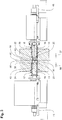
- Fig. 1 shows a reel 10 with a arranged on a reel axis 11 coiler mandrel 12, which is executed axially divided and a first Has coiler mandrel element 13 and a second coiler mandrel element 14.
- the reel mandrel elements each have a coiler mandrel sub-shaft 15, 16, which in turn are in each case displaceable relative to a spreading segment arrangement 17, 18.
- the coiler mandrel sub-shafts 15, 16 are connected to one another at their coupling ends 19, 20 via a shaft coupling 21.
- the shaft coupling 21 is formed in the case of the illustrated embodiment as a plug coupling and has a connected to the coupling end 20 of the coiler mandrel shaft 16 plug part 22, which serves for axial engagement in a arranged at the coupling end 19 of the coiler mandrel shaft 15 female part 23 of the shaft coupling 21.
- the reel 10 has two frame means 24, 25 which serve respectively for receiving and supporting a coiler mandrel element 13, 14.
- the left frame device 24 is provided with a drive gear 26 which is connected on the input side with a drive motor, not shown, and the output side via a arranged on the coiler mandrel element 13 gear 29, the transmission of a drive torque to one in the frame device 24 in coiler mandrel bearings 30 rotatable stored reel mandrel sheath 31 makes it possible.
- the coiler mandrel element 13 of the frame device 24 which is mounted rotatably in the frame device 25 via a coiler mandrel 32, is not provided with a drive device in the exemplary embodiment shown.
- the coiler mandrel elements 13, 14 are each constructed so that the coiler mandrel sheath 31, 32 serves to receive the coiler mandrel sub-shaft 15, 16, wherein the coiler mandrel sub-shaft 15, 16 axially slidably housed in the coiler mandrel sheath 31, 32 and the transmission of a Torque between the coiler mandrel sheath 31, 32 and the coiler mandrel element 13, 14 allows.
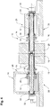
- the coiler mandrel sub-shafts 15, 16 are each provided at their end opposite the coupling end 19, 20 with a translation device 33 designed here as a hydraulic piston / cylinder unit. From the illustration in Fig. 4 It is clear that the operation of the translation device 33 causes a corresponding axial displacement of the reel mandrel shafts 15, 16 relative to the Sp Schwarzsegmentan extracten 17, 18, which are fixed axially to the coiler mandrel sheath 31, 32.
- the shows Fig. 1 the coiler mandrel elements 13, 14 in the engaged state, in which arranged on the coupling end 20 of the right coiler mandrel part shaft 15 plug part 22 of the shaft coupling 21 completely in the arranged on the coupling end 19 of the coiler mandrel shaft part 15 socket part 23 of the shaft coupling 21st engages, so that in the frame means 24 on the in Fig. 1 left coiler mandrel element 13 transmitted drive torque by means of the shaft coupling 21 is transmitted to the right reel mandrel element 14 of the frame means 25.
- Fig. 2 shows the reel 10 immediately before receiving a coil 40 arranged on a coil 40, wherein the coil 39 is disposed between the reel members 13, 14 on the reel axis 11.
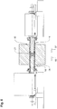
- left reel mandrel member 51 has a coiler mandrel sub-shaft 52, which, as Fig. 5 shows wedge surfaces 53 having a wedge surface arrangement 54 and a Sp Schwarzsegmentan Aunt 55 with wedge surfaces 58 having a wedge with the surfaces 43, 44 of the coiler mandrel element 14 matching wedge surface orientation.
- Fig. 5 shows wedge surfaces 53 having a wedge surface arrangement 54 and a Sp Schwarzsegmentan Aunt 55 with wedge surfaces 58 having a wedge with the surfaces 43, 44 of the coiler mandrel element 14 matching wedge surface orientation.
Description
Die Erfindung betrifft einen Haspel zum Aufwickeln von bandförmigem Material gemäß dem Oberbegriff des Anspruchs 1.
Haspeln der eingangs genannten Art werden beispielsweise bei der Bandherstellung in einem Walzverfahren eingesetzt, wo regelmäßig in einem Einweg- oder Reversierbetrieb das Band mit einem definierten Bandzug von einem ersten Haspel abgewickelt, durch einen Walzspalt einer Walzeneinrichtung hindurchbewegt und auf einem weiteren Haspel mit definiertem Bandzug aufgewickelt wird, um anschließend in einem nachfolgenden Walzgang nach mehrfach wiederholtem Durchlauf durch die Walzeneinrichtung auf den Haspel aufgewickelt zu werden bis die gewünschte Walzbandstärke erreicht ist. Ausgangsmaterial für ein derartiges Walzverfahren ist ein Walzband mit relativ großer Dicke, das zu Beginn des Walzverfahrens auf den ersten Haspel aufgenommen werden muss und nach Beendigung des Walzverfahrens als Walzband mit der gewünschten Dicke von dem Haspel abgenommen werden muss. Hiermit sind entsprechend häufig Beschickungsvorgänge verbunden, bei denen das bandförmige Material in Coilform auf einer Spule angeordnet vom Haspeldorn aufgenommen wird und nachfolgend eine Spreizung der Spreizsegmente zur Herstellung einer kraftschlüssigen Verbindung zwischen dem Haspeldorn und der Spule erfolgt.The invention relates to a reel for winding strip-shaped material according to the preamble of claim 1.
Reels of the type mentioned are used, for example, in strip production in a rolling process, where regularly in a one-way or reversing the tape unwound with a defined strip tension of a first reel, moved through a nip of a roller device and wound on another reel with defined strip tension is then to be wound up in a subsequent rolling pass after repeated repeated passage through the roller means on the reel until the desired rolled strip thickness is reached. Starting material for such a rolling process is a rolled strip with a relatively large thickness, which must be taken at the beginning of the rolling process on the first reel and must be removed after completion of the rolling process as a rolled strip of the desired thickness of the reel. This is correspondingly often associated with charging operations in which the band-shaped material arranged in coil form on a spool is taken up by the coiler mandrel and subsequently a spreading of the expansion segments for producing a frictional connection between the coiler mandrel and the coil.
Die bekannten Haspeln weisen hierzu einen Haspeldorn auf, der translatorisch von einer Seite in die Spule oder den Rohbund eingefahren wird, sodass das freie axiale Ende des Haspeldorns über die gesamte Länge der Spule oder des Rohbundes verfahren werden muss. Da bei diesem Vorgang Coils mit großen Massen bewegt werden, erfolgt die Verfahrbewegung relativ langsam, sodass für einen sogenannten "Bundwechsel", bei dem ein Coil bzw. eine Spule gegen eine andere ausgetauscht wird, entsprechend lange Verfahrzeiten für das Einfahren und Ausfahren des Haspeldorns benötigt werden. Hiermit sind entsprechende Stillstandzeiten der Walzanlagen verbunden, was zu einer Verringerung der Produktivität führt.The known reels have for this purpose a reel mandrel, which is moved translationally from one side into the coil or the Rohbund, so that the free axial end of the coiler mandrel must be moved over the entire length of the coil or the Rohbundes. Since in this process coils are moved with large masses, the movement is relatively slow, so that for a so-called "Bundwechsel" in which a coil or a coil is exchanged for another, correspondingly long travel times for retracting and extending the coiler mandrel needed become. This is associated with corresponding downtime of the rolling plants, resulting in a reduction in productivity.
Aus der
Der Erfindung liegt die Aufgabe zugrunde, einen Haspel vorzuschlagen, der die Übertragung größerer Kräfte auf die Spreizsegmentanordnungen ohne die Gefahr eines Bauteilversagens ermöglicht.The invention has for its object to provide a reel that allows the transmission of greater forces on the Spreizsegmentanordnungen without the risk of component failure.
Zur Lösung weist der erfindungsgemäße Haspel die Merkmale des Anspruchs 1 auf.To solve the reel invention has the features of claim 1.
Bei dem erfindungsgemäßen Haspel ist der Haspeldorn axial geteilt ausgeführt und weist ein erstes und ein zweites Haspeldornelement auf, die auf einer gemeinsamen Haspelachse angeordnet sind, wobei die Haspeldornelemente miteinander gegenüberliegenden Kupplungsenden axial gegeneinander verfahrbar und mittels einer zwischen den Kupplungsenden ausgebildeten Wellenkupplung miteinander verbindbar sind.In the reel according to the invention the reel mandrel is axially divided and has a first and a second coiler mandrel element, which are arranged on a common reel axis, wherein the coiler mandrel elements mutually opposite coupling ends axially movable relative to each other and by means of a formed between the coupling ends shaft coupling with each other.
Eine derartige zweigeteilte Ausführung des Haspeldorns mit zwei Haspeldornelementen, die daher von einander gegenüberliegenden Enden der Spule gegeneinander verfahren werden können, ermöglicht eine Verkürzung der Verfahrzeit auf die Hälfte der bislang benötigten Zeit. Darüber hinaus ermöglicht die Ausbildung des Haspeldorns aus zwei gegeneinander verfahrbaren Haspeldornelementen eine beidseitige Aufnahme bzw. Abstützung des Coils, sodass eine symmetrische Abstützung und damit auch eine wesentlich größere Laufruhe des Coils bei einem Wickelvorgang ermöglicht wird.Such a two-part design of the coiler mandrel with two coiler mandrel elements, which can therefore be moved from opposite ends of the coil against each other, allows a shortening of the travel time to half the time previously required. In addition, the formation of the coiler mandrel of two co-moving coiler mandrel elements enables a two-sided recording or support of the coil, so that a symmetrical support and thus a much greater smoothness of the coil is made possible during a winding process.
Insbesondere dann, wenn das Coil auf einer Spule aufgenommen ist, entlastet die auf den über die Wellenkupplung axial miteinander verbundenen Haspeldornelementen angeordnete Spule die Haspeldornwelle von dem durch das Gewicht des Coils induzierten Biegemoment. Im Gegensatz zu einer Haspel mit Gegenlager, bei dem das Coil von einem einseitig in das Coil eingefahrenen Haspeldorn aufgenommen wird, der somit durch das Gewicht des Coils auf Biegung belastet wird, wird bei dem erfindungsgemäßen Haspeldorn mit beidseitig in die Spule eingefahrenen Haspeldornelementen das Biegemoment von der Spule aufgenommen. Der Haspeldorn bzw. die Haspeldornelemente müssen daher lediglich entsprechend des auf sie wirkenden Drehmoments dimensioniert werden.In particular, when the coil is accommodated on a spool, the spool arranged on the over the shaft coupling axially interconnected coiler mandrel elements relieves the reel mandrel shaft of the induced by the weight of the coil bending moment. In contrast to a reel with an abutment, in which the coil is taken up by a unrolled in the coil coiler mandrel, which is thus loaded by the weight of the coil on bending, in the reel mandrel according to the invention with retracted on both sides in the coil reel mandrel elements, the bending moment of taken up the coil. The reel mandrel or the reel mandrel elements must therefore be dimensioned only according to the torque acting on them.
Darüber hinaus ermöglicht die Ausbildung des Haspeldorns aus zwei Haspeldornelementen bei vergleichbar großen Spreizkräften eine Übertragung wesentlich größerer Drehmomente zur Erzeugung der für den Walzprozess erforderlichen Bandzüge vom Haspeldorn auf die Spule als es bei einem einseitig in die Spule eingefahrenen Haspeldorn der Fall ist.In addition, the formation of the coiler mandrel from two coiler mandrel elements with comparably large spreading forces enables a transmission of substantially greater torques to produce the strip pulls required for the rolling process from the coiler mandrel to the reel, as is the case with a coiler mandrel inserted into the reel on one side.
Erfindungsgemäß sind die Haspeldornelemente jeweils in einer axial verfahrbaren Gestelleinrichtung angeordnet, wobei die Haspeldornelemente jeweils eine Haspeldornteilwelle aufweisen, auf der eine Spreizsegmentanordnung angeordnet ist, wobei die Haspeldornteilwellen mittels einer an der Gestelleinrichtung angeordneten Translationseinrichtung gegenüber der Spreizsegmentanordnung verfahrbar sind.According to the invention, the reel mandrel elements are each arranged in an axially displaceable frame device, wherein the reel mandrel elements each have a coiler mandrel part shaft on which a spreading segment arrangement is arranged, wherein the coiler mandrel part shafts can be moved relative to the spreading segment arrangement by means of a translation device arranged on the frame device.
Besonders bevorzugt ist es, wenn die Kupplungsenden an den Haspeldornteilwellen ausgebildet sind, und die Herstellung einer axialen Verbindung zwischen den Kupplungsenden zur Drehmomentübertragung zwischen den Haspeldornteilwellen und der Spule mittels der Translationseinrichtungen erfolgt. Damit dienen die Translationseinrichtungen nicht nur zum radialen Verfahren der Spreizsegmente, also zur Ausführung des Spreizvorgangs, sondern darüber hinaus auch gleichzeitig zur Herstellung des Kupplungsvorgangs, sodass trotz der zweigeteilten Ausgestaltung des Haspeldorns keine besonderen Einrichtungen zur Ausführung des Kupplungsvorgangs benötigt werden.It is particularly preferred if the coupling ends are formed on the coiler mandrel sub-shafts, and the production of an axial connection between the coupling ends for torque transmission between the coiler mandrel sub-waves and the coil by means of the translation means. Thus, the translation devices are not only for the radial process of Spreizsegmente, ie for performing the spreading process, but also at the same time for the preparation of the coupling process, so that despite the two-part design of the coiler mandrel no special means for carrying out the coupling process are needed.
Vorzugsweise ist die Wellenkupplung als Steckkupplung ausgebildet mit einem an einem Kupplungsende einer Haspeldornteilwelle angeordneten Steckerteil der Wellenkupplung, das mittels der Translationseinrichtung zur Drehmomentübertragung in ein Buchsenteil der Wellenkupplung am Kupplungsende der zweiten Haspeldornteilwelle mit definierter Einfahrtiefe einfahrbar ist.Preferably, the shaft coupling is designed as a plug-in coupling with a arranged at a coupling end of a coiler mandrel part shaft plug part of the shaft coupling, which is retractable by means of the translation device for torque transmission in a socket part of the shaft coupling at the coupling end of the second coiler mandrel sub-section with a defined depth of entry.
Wenn die Einfahrtiefe so definiert ist, dass die der Einfahrtiefe entsprechende Translationsbewegung der Haspeldornteilwellen jeweils die zur Erzeugung der gewünschten radial vorgespannten Aufnahme der Spule notwendige Radialbewegung bewirkt, kann allein mittels Ausführung des Kupplungsvorgangs die gewünschte radiale Vorspannung erzeugt werden.If the entry depth is defined such that the translational movement of the coiler mandrel part shafts corresponding to the entry depth respectively causes the radial movement necessary to produce the desired radially prestressed reception of the coil, the desired radial prestressing can be generated solely by executing the coupling process.
Gemäß einer vorteilhaften Ausführungsform sind die Translationseinrichtungen als koaxial zu den Haspeldornteilwellen angeordnete, auf den Kupplungsenden der Haspeldornteilwellen gegenüberliegende Wellenenden der Haspeldornteilwellen wirkende Kolben-/Zylinder- Einheiten ausgebildet, sodass eine besonders kompakte Ausgestaltung der Translationseinrichtungen möglich wird.According to an advantageous embodiment, the translation devices are arranged as coaxial with the coiler mandrel sub-waves, on the Coupling ends of the coiler mandrel part shafts opposite shaft ends of the coiler mandrel part shafts acting piston / cylinder units designed so that a particularly compact design of the translation devices is possible.
Die Translationseinrichtungen können gegensinnig wirkend ausgebildet sein, sodass also die Kupplungsenden der Haspeldornteilwellen zur Ausführung des Kupplungsvorgangs aufeinander zu bewegt werden, oder die Translationseinrichtungen können gleichsinnig wirkend ausgeführt sein, sodass die Kupplungsenden der Haspeldornteilwellen zur Ausführung des Kupplungsvorgangs in dieselbe Richtung bewegt werden.The translation means can be designed to act in opposite directions, so that the coupling ends of the coiler mandrel sub-shafts are moved towards each other for performing the coupling operation, or the translation means can be designed to act in the same direction, so that the coupling ends of the coiler mandrel sub-shafts are moved in the same direction to perform the coupling operation.
Nachfolgend wird eine bevorzugte Ausführungsform des Haspels anhand der Zeichnung näher erläutert.Hereinafter, a preferred embodiment of the reel will be explained with reference to the drawing.
Es zeigen
- Fig. 1
- einen Haspel mit über eine Wellenkupplung miteinander verbundenen Haspeldornelementen;
- Fig. 2
- den in
Fig. 1 dargestellten Haspel mit entkuppelten Haspeldornelementen vor Aufnahme eines Coils; - Fig. 3
- den in
Fig. 2 dargestellten Haspel nach Aufnahme des Coils während des Kupplungsvorgangs; - Fig. 4
- den in
Fig. 3 während des Kupplungsvorgangs dargestellten Haspel in Längsschnittdarstellung; - Fig. 5
- den in
Fig. 1 dargestellten Haspel mit alternativ ausgebildeten Haspeldornelementen während des Kupplungsvorgangs; - Fig. 6
- den in
Fig. 5 dargestellten Haspel nach Ausführung des Kupplungsvorgangs.
- Fig. 1
- a reel having reel mandrel members interconnected by a shaft coupling;
- Fig. 2
- the in
Fig. 1 shown reel with decoupled coiler mandrel elements before receiving a coil; - Fig. 3
- the in
Fig. 2 shown reel after receiving the coil during the coupling process; - Fig. 4
- the in
Fig. 3 during the coupling process shown reel in longitudinal section; - Fig. 5
- the in
Fig. 1 illustrated reel with alternately formed coiler mandrel elements during the coupling process; - Fig. 6
- the in
Fig. 5 shown reel after execution of the coupling process.
Zur Herstellung einer axialen, ein Drehmoment übertragenden Verbindung der Haspeldornelemente 13, 14 sind die Haspeldornteilwellen 15, 16 an ihren Kupplungsenden 19, 20 über eine Wellenkupplung 21 miteinander verbunden. Die Wellenkupplung 21 ist im Falle des dargestellten Ausführungsbeispiels als Steckerkupplung ausgebildet und weist ein mit dem Kupplungsende 20 der Haspeldornteilwelle 16 verbundenes Steckerteil 22 auf, das zum axialen Eingriff in ein am Kupplungsende 19 der Haspeldornteilwelle 15 angeordnetes Buchsenteil 23 der Wellenkupplung 21 dient.
Wie sich aus einer Zusammenschau der
Im Gegensatz zu dem Haspeldornelement 13 der Gestelleinrichtung 24 ist das Haspeldornelement 14, das über einen Haspeldornmantel 32 drehbar in der Gestelleinrichtung 25 gelagert ist, in dem dargestellten Ausführungsbeispiel nicht mit einer Antriebseinrichtung versehen. Übereinstimmend sind die Haspeldornelemente 13, 14 jeweils so aufgebaut, dass der Haspeldornmantel 31, 32 zur Aufnahme der Haspeldornteilwelle 15, 16 dient, wobei die Haspeldornteilwelle 15, 16 axial verschiebbar im Haspeldornmantel 31, 32 aufgenommen ist und die Übertragung eines Drehmoments zwischen dem Haspeldornmantel 31, 32 und dem Haspeldornelement 13, 14 ermöglicht.
To produce an axial, torque-transmitting connection of the
As can be seen from a synopsis of
In contrast to the
Zur Durchführung einer axialen Verschiebung in Richtung der Haspelachse 11 sind die Haspeldornteilwellen 15, 16 jeweils an ihrem dem Kupplungsende 19, 20 gegenüberliegenden Ende mit einer hier als hydraulische Kolben-/Zylinder-Einheit ausgeführten Translationseinrichtung 33 versehen. Aus der Darstellung in
Wie ferner eine Zusammenschau der
Wie bereits erwähnt, zeigt die
Wie
Ausgehend von der in
Abweichend von den übereinstimmend ausgebildeten Haspeldornteilwellen 15, 16 und Spreizsegmentanordnungen 17, 18 der Haspeldornelemente 13, 14 in den
Ausgehend von der in
Claims (7)
- A reel (10) for winding strip-shaped material on a reel mandrel (12, 50), which can be driven by means of a drive device and which is provided with expansion segments (35) for a radially pre-loaded reception of a spool (39), said expansion segments (35) being able to be radially spread apart so as to enlarge the diameter of the reel mandrel, which is axially divided and which comprises a first and a second reel-mandrel element (13, 14, 51) arranged on a shared reel axis (11), said reel-mandrel elements, which comprise coupling ends opposite each other, being able to axially displaced against each other and being able to be connected to each other by means of a shaft coupling (21) formed between the coupling ends, said reel-mandrel elements (13, 14, 51) each being arranged in an axially displaceable (45) framework device (24, 25), said reel-mandrel elements (13, 14, 51) each comprising a reel-mandrel partial shaft (15, 16, 52), on which an expansion-segment arrangement (17, 18, 55) comprising the corresponding expansion segments (35) is arranged,
characterized in that
the reel-mandrel partial shafts can be axially displaced with respect to the expansion-segment arrangement by means of a translation device (33) arranged on the framework device in order to enlarge the diameter of the reel mandrel. - The reel according to claim 1,
characterized in that
the coupling ends (19, 20) are formed on the reel-mandrel partial shafts (15, 16, 52) and an axial connection between the coupling ends for transferring torque between the reel-mandrel partial shafts is produced by means of the translation devices (33). - The reel according to claim 2,
characterized in that
the shaft coupling (21) is realized as a plug-in coupling having a plug part (22) of the shaft coupling (21) formed on a coupling end (20) of a reel-mandrel partial shaft (16), said plug part (22) being able to be inserted into a receiver part (23) of the shaft coupling at the coupling end (19) of the second reel-mandrel partial shaft (15) at a predefined insertion depth by means of the translation device (33) for transferring torque. - The reel according to claim 3,
characterized in that
the insertion depth is defined such that the translational movement of the reel-mandrel partial shafts (15, 16, 52) corresponding to the insertion depth causes the corresponding radial movement of the expansion segments (35) required for generating the desired radially pre-loaded reception of the spool (39) in each instance. - The reel according to any one of the preceding claims,
characterized in that
the translation devices (33) are realized as piston/cylinder units arranged coaxially to the reel-mandrel partial shafts (15, 16, 52) and acting on the shaft ends of the reel-mandrel partial shafts opposite the coupling ends of the reel-mandrel partial shafts. - The reel according to any one of the preceding claims,
characterized in that
the translation devices (33) act in opposite directions. - The reel according to any one of the preceding claims,
characterized in that
the translation devices (33) act in the same direction.
Applications Claiming Priority (1)
| Application Number | Priority Date | Filing Date | Title |
|---|---|---|---|
| DE102014200942.1A DE102014200942B4 (en) | 2014-01-20 | 2014-01-20 | Reel for winding strip-shaped material |
Publications (2)
| Publication Number | Publication Date |
|---|---|
| EP2896465A1 EP2896465A1 (en) | 2015-07-22 |
| EP2896465B1 true EP2896465B1 (en) | 2018-03-07 |
Family
ID=52292797
Family Applications (1)
| Application Number | Title | Priority Date | Filing Date |
|---|---|---|---|
| EP15150604.5A Active EP2896465B1 (en) | 2014-01-20 | 2015-01-09 | Reel for winding up material in strip form |
Country Status (3)
| Country | Link |
|---|---|
| EP (1) | EP2896465B1 (en) |
| CN (2) | CN104787605A (en) |
| DE (1) | DE102014200942B4 (en) |
Cited By (2)
| Publication number | Priority date | Publication date | Assignee | Title |
|---|---|---|---|---|
| WO2022156955A2 (en) | 2021-01-25 | 2022-07-28 | Achenbach Buschhütten GmbH & Co. KG | Reel for winding or unwinding material in strip form, and method |
| DE102021101531A1 (en) | 2021-01-25 | 2022-07-28 | Achenbach Buschhütten GmbH & Co. KG | Coil for winding or unwinding strip-shaped material and method |
Families Citing this family (2)
| Publication number | Priority date | Publication date | Assignee | Title |
|---|---|---|---|---|
| CN106429559A (en) * | 2016-11-01 | 2017-02-22 | 芜湖光荣网络科技有限公司 | Breathable tape production fixing device |
| CN115156334B (en) * | 2022-07-08 | 2023-04-07 | 智腾自动化科技河北有限公司 | Automatic power expansion and contraction uncoiler |
Citations (11)
| Publication number | Priority date | Publication date | Assignee | Title |
|---|---|---|---|---|
| US2117640A (en) | 1936-11-24 | 1938-05-17 | Wean Engineering Co Inc | Coiling reel |
| GB925755A (en) | 1960-11-18 | 1963-05-08 | August Schmitz | Unreeling apparatus for strip materials |
| US4105172A (en) | 1977-03-11 | 1978-08-08 | Mesta Machine Company | Tension reel for strip coiling |
| DE2818042A1 (en) | 1978-04-25 | 1979-11-08 | Schloemann Siemag Ag | PROCEDURE FOR OPERATING A ROLLED STRIP REEL AND ROLLED STRIP REEL FOR EXERCISING THE PROCESS |
| JPS5524713A (en) | 1978-08-09 | 1980-02-22 | Hitachi Ltd | Double mandrel type reel |
| DE3150319A1 (en) | 1981-12-18 | 1983-06-30 | Bajzur, Ljudmila Grigor'evna, Kramatorsk | Reel for metal strip |
| JPH01143716A (en) | 1987-11-30 | 1989-06-06 | Hitachi Ltd | Take-up machine, unwinding machine for steel strip coil |
| DE4335258A1 (en) | 1993-10-15 | 1995-04-20 | Hans Dr Ing Grimm | Pneumatic/mechanical clamping device for winding shafts, clamping heads and the like |
| JPH10137848A (en) | 1996-11-01 | 1998-05-26 | Ishikawajima Harima Heavy Ind Co Ltd | Coil take-up device |
| DE102006038493A1 (en) | 2006-08-16 | 2008-02-21 | Sms Demag Ag | Doppelspreizkopf-Karusselhaspel |
| DE102008053673A1 (en) | 2007-11-01 | 2009-05-14 | Fuji Tekko Co., Ltd., Neyagawa | Fabric winding process |
-
2014
- 2014-01-20 DE DE102014200942.1A patent/DE102014200942B4/en not_active Expired - Fee Related
-
2015
- 2015-01-09 EP EP15150604.5A patent/EP2896465B1/en active Active
- 2015-01-20 CN CN201510026656.5A patent/CN104787605A/en active Pending
- 2015-01-20 CN CN201520036063.2U patent/CN204896900U/en active Active
Patent Citations (11)
| Publication number | Priority date | Publication date | Assignee | Title |
|---|---|---|---|---|
| US2117640A (en) | 1936-11-24 | 1938-05-17 | Wean Engineering Co Inc | Coiling reel |
| GB925755A (en) | 1960-11-18 | 1963-05-08 | August Schmitz | Unreeling apparatus for strip materials |
| US4105172A (en) | 1977-03-11 | 1978-08-08 | Mesta Machine Company | Tension reel for strip coiling |
| DE2818042A1 (en) | 1978-04-25 | 1979-11-08 | Schloemann Siemag Ag | PROCEDURE FOR OPERATING A ROLLED STRIP REEL AND ROLLED STRIP REEL FOR EXERCISING THE PROCESS |
| JPS5524713A (en) | 1978-08-09 | 1980-02-22 | Hitachi Ltd | Double mandrel type reel |
| DE3150319A1 (en) | 1981-12-18 | 1983-06-30 | Bajzur, Ljudmila Grigor'evna, Kramatorsk | Reel for metal strip |
| JPH01143716A (en) | 1987-11-30 | 1989-06-06 | Hitachi Ltd | Take-up machine, unwinding machine for steel strip coil |
| DE4335258A1 (en) | 1993-10-15 | 1995-04-20 | Hans Dr Ing Grimm | Pneumatic/mechanical clamping device for winding shafts, clamping heads and the like |
| JPH10137848A (en) | 1996-11-01 | 1998-05-26 | Ishikawajima Harima Heavy Ind Co Ltd | Coil take-up device |
| DE102006038493A1 (en) | 2006-08-16 | 2008-02-21 | Sms Demag Ag | Doppelspreizkopf-Karusselhaspel |
| DE102008053673A1 (en) | 2007-11-01 | 2009-05-14 | Fuji Tekko Co., Ltd., Neyagawa | Fabric winding process |
Cited By (5)
| Publication number | Priority date | Publication date | Assignee | Title |
|---|---|---|---|---|
| WO2022156955A2 (en) | 2021-01-25 | 2022-07-28 | Achenbach Buschhütten GmbH & Co. KG | Reel for winding or unwinding material in strip form, and method |
| DE102021101531A1 (en) | 2021-01-25 | 2022-07-28 | Achenbach Buschhütten GmbH & Co. KG | Coil for winding or unwinding strip-shaped material and method |
| DE102021101530A1 (en) | 2021-01-25 | 2022-07-28 | Achenbach Buschhütten GmbH & Co. KG | Coil for winding or unwinding strip-shaped material and method |
| WO2022156957A1 (en) | 2021-01-25 | 2022-07-28 | Achenbach Buschhütten GmbH & Co. KG | Coiler for winding up or unwinding strip-shaped material, and method |
| DE102021101531B4 (en) | 2021-01-25 | 2022-10-20 | Achenbach Buschhütten GmbH & Co. KG | Coil for winding or unwinding strip-shaped material and method |
Also Published As
| Publication number | Publication date |
|---|---|
| EP2896465A1 (en) | 2015-07-22 |
| CN204896900U (en) | 2015-12-23 |
| DE102014200942A1 (en) | 2015-07-23 |
| DE102014200942B4 (en) | 2019-01-10 |
| CN104787605A (en) | 2015-07-22 |
Similar Documents
| Publication | Publication Date | Title |
|---|---|---|
| EP2896465B1 (en) | Reel for winding up material in strip form | |
| EP3804106B1 (en) | Insertion of coils into a laminated stator core | |
| DE1556444B2 (en) | LAPPIPE AND DEVICE FOR FORMING LAPPROUBE, IN PARTICULAR THOSE FOR USE IN THE SPACE INDUSTRY | |
| EP3031758A1 (en) | Winding shaft and method for inserting a winding shaft in a winding device | |
| DE102011077569A1 (en) | drum | |
| DE2527690B2 (en) | TAPE REEL FOR REWINDING AND UNWINDING METAL STRIP | |
| DE102014003602A1 (en) | Method for producing a winding | |
| EP2128877B1 (en) | Device and method for coiling a flat wire | |
| DE1948805A1 (en) | Method and device for producing ring-shaped blanks for toothed rims and other ring-shaped components | |
| DE102005034031A1 (en) | Rolling mill and method for producing a metal strip | |
| DE2721729A1 (en) | Winding mandrel for hot-rolled strip | |
| EP3052255B1 (en) | Device for winding a strip material into a coil | |
| EP1948422B1 (en) | Method and apparatus for manufacturing a wrap-around tube | |
| EP3025800B1 (en) | Reel for winding up material in strip form | |
| DE102014212436A1 (en) | Device for positioning a plurality of a recess for a shaft having functional elements | |
| EP2881185A1 (en) | Method and device for producing a metallic strip in casting and rolling | |
| DE102013224396A1 (en) | Circular bending device and method for forming band sections to round bodies, in particular sleeves, by bending around the peripheral surface of a round bending core | |
| DE102017124859A1 (en) | Method for producing an electric coil and winding device | |
| DE102010031105A1 (en) | Outer laminated core manufacturing method for electric machine, involves arranging teeth of strip in intermediate spaces between base elements such that normal vector of respective tooth comprises radial components | |
| DE102016123143B4 (en) | Winding device with a winding core that can be changed in diameter | |
| DE2905179A1 (en) | CONTINUOUS ROLLING MILL | |
| EP2138248B1 (en) | Bending method for cone-shaped pipes | |
| DE1752185C3 (en) | Reel for rolled strip | |
| DE102006062168A1 (en) | Method and device for drawing impact-welded pipes | |
| DE102018212958A1 (en) | Reversible reel and method for its operation |
Legal Events
| Date | Code | Title | Description |
|---|---|---|---|
| PUAI | Public reference made under article 153(3) epc to a published international application that has entered the european phase |
Free format text: ORIGINAL CODE: 0009012 |
|
| 17P | Request for examination filed |
Effective date: 20150130 |
|
| AK | Designated contracting states |
Kind code of ref document: A1 Designated state(s): AL AT BE BG CH CY CZ DE DK EE ES FI FR GB GR HR HU IE IS IT LI LT LU LV MC MK MT NL NO PL PT RO RS SE SI SK SM TR |
|
| AX | Request for extension of the european patent |
Extension state: BA ME |
|
| 17Q | First examination report despatched |
Effective date: 20150805 |
|
| STAA | Information on the status of an ep patent application or granted ep patent |
Free format text: STATUS: EXAMINATION IS IN PROGRESS |
|
| GRAP | Despatch of communication of intention to grant a patent |
Free format text: ORIGINAL CODE: EPIDOSNIGR1 |
|
| STAA | Information on the status of an ep patent application or granted ep patent |
Free format text: STATUS: GRANT OF PATENT IS INTENDED |
|
| INTG | Intention to grant announced |
Effective date: 20170918 |
|
| GRAS | Grant fee paid |
Free format text: ORIGINAL CODE: EPIDOSNIGR3 |
|
| GRAA | (expected) grant |
Free format text: ORIGINAL CODE: 0009210 |
|
| STAA | Information on the status of an ep patent application or granted ep patent |
Free format text: STATUS: THE PATENT HAS BEEN GRANTED |
|
| AK | Designated contracting states |
Kind code of ref document: B1 Designated state(s): AL AT BE BG CH CY CZ DE DK EE ES FI FR GB GR HR HU IE IS IT LI LT LU LV MC MK MT NL NO PL PT RO RS SE SI SK SM TR |
|
| REG | Reference to a national code |
Ref country code: GB Ref legal event code: FG4D Free format text: NOT ENGLISH |
|
| REG | Reference to a national code |
Ref country code: CH Ref legal event code: EP Ref country code: AT Ref legal event code: REF Ref document number: 975996 Country of ref document: AT Kind code of ref document: T Effective date: 20180315 |
|
| REG | Reference to a national code |
Ref country code: IE Ref legal event code: FG4D Free format text: LANGUAGE OF EP DOCUMENT: GERMAN |
|
| REG | Reference to a national code |
Ref country code: DE Ref legal event code: R096 Ref document number: 502015003276 Country of ref document: DE |
|
| REG | Reference to a national code |
Ref country code: NL Ref legal event code: MP Effective date: 20180307 |
|
| REG | Reference to a national code |
Ref country code: LT Ref legal event code: MG4D |
|
| PG25 | Lapsed in a contracting state [announced via postgrant information from national office to epo] |
Ref country code: ES Free format text: LAPSE BECAUSE OF FAILURE TO SUBMIT A TRANSLATION OF THE DESCRIPTION OR TO PAY THE FEE WITHIN THE PRESCRIBED TIME-LIMIT Effective date: 20180307 Ref country code: CY Free format text: LAPSE BECAUSE OF FAILURE TO SUBMIT A TRANSLATION OF THE DESCRIPTION OR TO PAY THE FEE WITHIN THE PRESCRIBED TIME-LIMIT Effective date: 20180307 Ref country code: NO Free format text: LAPSE BECAUSE OF FAILURE TO SUBMIT A TRANSLATION OF THE DESCRIPTION OR TO PAY THE FEE WITHIN THE PRESCRIBED TIME-LIMIT Effective date: 20180607 Ref country code: FI Free format text: LAPSE BECAUSE OF FAILURE TO SUBMIT A TRANSLATION OF THE DESCRIPTION OR TO PAY THE FEE WITHIN THE PRESCRIBED TIME-LIMIT Effective date: 20180307 Ref country code: LT Free format text: LAPSE BECAUSE OF FAILURE TO SUBMIT A TRANSLATION OF THE DESCRIPTION OR TO PAY THE FEE WITHIN THE PRESCRIBED TIME-LIMIT Effective date: 20180307 Ref country code: HR Free format text: LAPSE BECAUSE OF FAILURE TO SUBMIT A TRANSLATION OF THE DESCRIPTION OR TO PAY THE FEE WITHIN THE PRESCRIBED TIME-LIMIT Effective date: 20180307 |
|
| PG25 | Lapsed in a contracting state [announced via postgrant information from national office to epo] |
Ref country code: RS Free format text: LAPSE BECAUSE OF FAILURE TO SUBMIT A TRANSLATION OF THE DESCRIPTION OR TO PAY THE FEE WITHIN THE PRESCRIBED TIME-LIMIT Effective date: 20180307 Ref country code: GR Free format text: LAPSE BECAUSE OF FAILURE TO SUBMIT A TRANSLATION OF THE DESCRIPTION OR TO PAY THE FEE WITHIN THE PRESCRIBED TIME-LIMIT Effective date: 20180608 Ref country code: BG Free format text: LAPSE BECAUSE OF FAILURE TO SUBMIT A TRANSLATION OF THE DESCRIPTION OR TO PAY THE FEE WITHIN THE PRESCRIBED TIME-LIMIT Effective date: 20180607 Ref country code: SE Free format text: LAPSE BECAUSE OF FAILURE TO SUBMIT A TRANSLATION OF THE DESCRIPTION OR TO PAY THE FEE WITHIN THE PRESCRIBED TIME-LIMIT Effective date: 20180307 Ref country code: LV Free format text: LAPSE BECAUSE OF FAILURE TO SUBMIT A TRANSLATION OF THE DESCRIPTION OR TO PAY THE FEE WITHIN THE PRESCRIBED TIME-LIMIT Effective date: 20180307 |
|
| PG25 | Lapsed in a contracting state [announced via postgrant information from national office to epo] |
Ref country code: MT Free format text: LAPSE BECAUSE OF FAILURE TO SUBMIT A TRANSLATION OF THE DESCRIPTION OR TO PAY THE FEE WITHIN THE PRESCRIBED TIME-LIMIT Effective date: 20180307 |
|
| PG25 | Lapsed in a contracting state [announced via postgrant information from national office to epo] |
Ref country code: RO Free format text: LAPSE BECAUSE OF FAILURE TO SUBMIT A TRANSLATION OF THE DESCRIPTION OR TO PAY THE FEE WITHIN THE PRESCRIBED TIME-LIMIT Effective date: 20180307 Ref country code: NL Free format text: LAPSE BECAUSE OF FAILURE TO SUBMIT A TRANSLATION OF THE DESCRIPTION OR TO PAY THE FEE WITHIN THE PRESCRIBED TIME-LIMIT Effective date: 20180307 Ref country code: PL Free format text: LAPSE BECAUSE OF FAILURE TO SUBMIT A TRANSLATION OF THE DESCRIPTION OR TO PAY THE FEE WITHIN THE PRESCRIBED TIME-LIMIT Effective date: 20180307 Ref country code: EE Free format text: LAPSE BECAUSE OF FAILURE TO SUBMIT A TRANSLATION OF THE DESCRIPTION OR TO PAY THE FEE WITHIN THE PRESCRIBED TIME-LIMIT Effective date: 20180307 Ref country code: AL Free format text: LAPSE BECAUSE OF FAILURE TO SUBMIT A TRANSLATION OF THE DESCRIPTION OR TO PAY THE FEE WITHIN THE PRESCRIBED TIME-LIMIT Effective date: 20180307 |
|
| PG25 | Lapsed in a contracting state [announced via postgrant information from national office to epo] |
Ref country code: SM Free format text: LAPSE BECAUSE OF FAILURE TO SUBMIT A TRANSLATION OF THE DESCRIPTION OR TO PAY THE FEE WITHIN THE PRESCRIBED TIME-LIMIT Effective date: 20180307 Ref country code: SK Free format text: LAPSE BECAUSE OF FAILURE TO SUBMIT A TRANSLATION OF THE DESCRIPTION OR TO PAY THE FEE WITHIN THE PRESCRIBED TIME-LIMIT Effective date: 20180307 Ref country code: CZ Free format text: LAPSE BECAUSE OF FAILURE TO SUBMIT A TRANSLATION OF THE DESCRIPTION OR TO PAY THE FEE WITHIN THE PRESCRIBED TIME-LIMIT Effective date: 20180307 |
|
| REG | Reference to a national code |
Ref country code: DE Ref legal event code: R026 Ref document number: 502015003276 Country of ref document: DE |
|
| PLBI | Opposition filed |
Free format text: ORIGINAL CODE: 0009260 |
|
| PLAX | Notice of opposition and request to file observation + time limit sent |
Free format text: ORIGINAL CODE: EPIDOSNOBS2 |
|
| PG25 | Lapsed in a contracting state [announced via postgrant information from national office to epo] |
Ref country code: PT Free format text: LAPSE BECAUSE OF FAILURE TO SUBMIT A TRANSLATION OF THE DESCRIPTION OR TO PAY THE FEE WITHIN THE PRESCRIBED TIME-LIMIT Effective date: 20180709 |
|
| 26 | Opposition filed |
Opponent name: SMS GROUP GMBH Effective date: 20181207 |
|
| PG25 | Lapsed in a contracting state [announced via postgrant information from national office to epo] |
Ref country code: DK Free format text: LAPSE BECAUSE OF FAILURE TO SUBMIT A TRANSLATION OF THE DESCRIPTION OR TO PAY THE FEE WITHIN THE PRESCRIBED TIME-LIMIT Effective date: 20180307 |
|
| PG25 | Lapsed in a contracting state [announced via postgrant information from national office to epo] |
Ref country code: SI Free format text: LAPSE BECAUSE OF FAILURE TO SUBMIT A TRANSLATION OF THE DESCRIPTION OR TO PAY THE FEE WITHIN THE PRESCRIBED TIME-LIMIT Effective date: 20180307 |
|
| PLBB | Reply of patent proprietor to notice(s) of opposition received |
Free format text: ORIGINAL CODE: EPIDOSNOBS3 |
|
| PG25 | Lapsed in a contracting state [announced via postgrant information from national office to epo] |
Ref country code: MC Free format text: LAPSE BECAUSE OF FAILURE TO SUBMIT A TRANSLATION OF THE DESCRIPTION OR TO PAY THE FEE WITHIN THE PRESCRIBED TIME-LIMIT Effective date: 20180307 |
|
| REG | Reference to a national code |
Ref country code: CH Ref legal event code: PL |
|
| PG25 | Lapsed in a contracting state [announced via postgrant information from national office to epo] |
Ref country code: LU Free format text: LAPSE BECAUSE OF NON-PAYMENT OF DUE FEES Effective date: 20190109 |
|
| REG | Reference to a national code |
Ref country code: BE Ref legal event code: MM Effective date: 20190131 |
|
| REG | Reference to a national code |
Ref country code: IE Ref legal event code: MM4A |
|
| PG25 | Lapsed in a contracting state [announced via postgrant information from national office to epo] |
Ref country code: BE Free format text: LAPSE BECAUSE OF NON-PAYMENT OF DUE FEES Effective date: 20190131 |
|
| PG25 | Lapsed in a contracting state [announced via postgrant information from national office to epo] |
Ref country code: CH Free format text: LAPSE BECAUSE OF NON-PAYMENT OF DUE FEES Effective date: 20190131 Ref country code: LI Free format text: LAPSE BECAUSE OF NON-PAYMENT OF DUE FEES Effective date: 20190131 |
|
| PLCK | Communication despatched that opposition was rejected |
Free format text: ORIGINAL CODE: EPIDOSNREJ1 |
|
| PG25 | Lapsed in a contracting state [announced via postgrant information from national office to epo] |
Ref country code: IE Free format text: LAPSE BECAUSE OF NON-PAYMENT OF DUE FEES Effective date: 20190109 |
|
| REG | Reference to a national code |
Ref country code: DE Ref legal event code: R100 Ref document number: 502015003276 Country of ref document: DE |
|
| PLBN | Opposition rejected |
Free format text: ORIGINAL CODE: 0009273 |
|
| STAA | Information on the status of an ep patent application or granted ep patent |
Free format text: STATUS: OPPOSITION REJECTED |
|
| 27O | Opposition rejected |
Effective date: 20200202 |
|
| PG25 | Lapsed in a contracting state [announced via postgrant information from national office to epo] |
Ref country code: IS Free format text: LAPSE BECAUSE OF FAILURE TO SUBMIT A TRANSLATION OF THE DESCRIPTION OR TO PAY THE FEE WITHIN THE PRESCRIBED TIME-LIMIT Effective date: 20180707 |
|
| PG25 | Lapsed in a contracting state [announced via postgrant information from national office to epo] |
Ref country code: HU Free format text: LAPSE BECAUSE OF FAILURE TO SUBMIT A TRANSLATION OF THE DESCRIPTION OR TO PAY THE FEE WITHIN THE PRESCRIBED TIME-LIMIT; INVALID AB INITIO Effective date: 20150109 |
|
| PG25 | Lapsed in a contracting state [announced via postgrant information from national office to epo] |
Ref country code: MK Free format text: LAPSE BECAUSE OF FAILURE TO SUBMIT A TRANSLATION OF THE DESCRIPTION OR TO PAY THE FEE WITHIN THE PRESCRIBED TIME-LIMIT Effective date: 20180307 |
|
| PGFP | Annual fee paid to national office [announced via postgrant information from national office to epo] |
Ref country code: FR Payment date: 20230123 Year of fee payment: 9 Ref country code: AT Payment date: 20230118 Year of fee payment: 9 |
|
| PGFP | Annual fee paid to national office [announced via postgrant information from national office to epo] |
Ref country code: TR Payment date: 20230109 Year of fee payment: 9 Ref country code: IT Payment date: 20230131 Year of fee payment: 9 Ref country code: GB Payment date: 20230124 Year of fee payment: 9 Ref country code: DE Payment date: 20230320 Year of fee payment: 9 |
|
| P01 | Opt-out of the competence of the unified patent court (upc) registered |
Effective date: 20230527 |