EP2896372A1 - Image diagnosis device and image processing method - Google Patents
Image diagnosis device and image processing method Download PDFInfo
- Publication number
- EP2896372A1 EP2896372A1 EP12884676.3A EP12884676A EP2896372A1 EP 2896372 A1 EP2896372 A1 EP 2896372A1 EP 12884676 A EP12884676 A EP 12884676A EP 2896372 A1 EP2896372 A1 EP 2896372A1
- Authority
- EP
- European Patent Office
- Prior art keywords
- sectional image
- cross
- ultrasonic
- transceiver
- optical
- Prior art date
- Legal status (The legal status is an assumption and is not a legal conclusion. Google has not performed a legal analysis and makes no representation as to the accuracy of the status listed.)
- Granted
Links
Images





Classifications
-
- A—HUMAN NECESSITIES
- A61—MEDICAL OR VETERINARY SCIENCE; HYGIENE
- A61B—DIAGNOSIS; SURGERY; IDENTIFICATION
- A61B8/00—Diagnosis using ultrasonic, sonic or infrasonic waves
- A61B8/44—Constructional features of the ultrasonic, sonic or infrasonic diagnostic device
- A61B8/4416—Constructional features of the ultrasonic, sonic or infrasonic diagnostic device related to combined acquisition of different diagnostic modalities, e.g. combination of ultrasound and X-ray acquisitions
-
- A—HUMAN NECESSITIES
- A61—MEDICAL OR VETERINARY SCIENCE; HYGIENE
- A61B—DIAGNOSIS; SURGERY; IDENTIFICATION
- A61B5/00—Measuring for diagnostic purposes; Identification of persons
- A61B5/0033—Features or image-related aspects of imaging apparatus, e.g. for MRI, optical tomography or impedance tomography apparatus; Arrangements of imaging apparatus in a room
- A61B5/0035—Features or image-related aspects of imaging apparatus, e.g. for MRI, optical tomography or impedance tomography apparatus; Arrangements of imaging apparatus in a room adapted for acquisition of images from more than one imaging mode, e.g. combining MRI and optical tomography
-
- A—HUMAN NECESSITIES
- A61—MEDICAL OR VETERINARY SCIENCE; HYGIENE
- A61B—DIAGNOSIS; SURGERY; IDENTIFICATION
- A61B5/00—Measuring for diagnostic purposes; Identification of persons
- A61B5/0059—Measuring for diagnostic purposes; Identification of persons using light, e.g. diagnosis by transillumination, diascopy, fluorescence
- A61B5/0062—Arrangements for scanning
- A61B5/0066—Optical coherence imaging
-
- A—HUMAN NECESSITIES
- A61—MEDICAL OR VETERINARY SCIENCE; HYGIENE
- A61B—DIAGNOSIS; SURGERY; IDENTIFICATION
- A61B5/00—Measuring for diagnostic purposes; Identification of persons
- A61B5/02—Detecting, measuring or recording for evaluating the cardiovascular system, e.g. pulse, heart rate, blood pressure or blood flow
- A61B5/026—Measuring blood flow
- A61B5/0261—Measuring blood flow using optical means, e.g. infrared light
-
- A—HUMAN NECESSITIES
- A61—MEDICAL OR VETERINARY SCIENCE; HYGIENE
- A61B—DIAGNOSIS; SURGERY; IDENTIFICATION
- A61B8/00—Diagnosis using ultrasonic, sonic or infrasonic waves
- A61B8/08—Clinical applications
- A61B8/0891—Clinical applications for diagnosis of blood vessels
-
- A—HUMAN NECESSITIES
- A61—MEDICAL OR VETERINARY SCIENCE; HYGIENE
- A61B—DIAGNOSIS; SURGERY; IDENTIFICATION
- A61B8/00—Diagnosis using ultrasonic, sonic or infrasonic waves
- A61B8/12—Diagnosis using ultrasonic, sonic or infrasonic waves in body cavities or body tracts, e.g. by using catheters
-
- A—HUMAN NECESSITIES
- A61—MEDICAL OR VETERINARY SCIENCE; HYGIENE
- A61B—DIAGNOSIS; SURGERY; IDENTIFICATION
- A61B8/00—Diagnosis using ultrasonic, sonic or infrasonic waves
- A61B8/44—Constructional features of the ultrasonic, sonic or infrasonic diagnostic device
- A61B8/4444—Constructional features of the ultrasonic, sonic or infrasonic diagnostic device related to the probe
- A61B8/445—Details of catheter construction
-
- A—HUMAN NECESSITIES
- A61—MEDICAL OR VETERINARY SCIENCE; HYGIENE
- A61B—DIAGNOSIS; SURGERY; IDENTIFICATION
- A61B8/00—Diagnosis using ultrasonic, sonic or infrasonic waves
- A61B8/08—Clinical applications
- A61B8/0858—Clinical applications involving measuring tissue layers, e.g. skin, interfaces
-
- A—HUMAN NECESSITIES
- A61—MEDICAL OR VETERINARY SCIENCE; HYGIENE
- A61B—DIAGNOSIS; SURGERY; IDENTIFICATION
- A61B8/00—Diagnosis using ultrasonic, sonic or infrasonic waves
- A61B8/46—Ultrasonic, sonic or infrasonic diagnostic devices with special arrangements for interfacing with the operator or the patient
- A61B8/467—Ultrasonic, sonic or infrasonic diagnostic devices with special arrangements for interfacing with the operator or the patient characterised by special input means
- A61B8/469—Ultrasonic, sonic or infrasonic diagnostic devices with special arrangements for interfacing with the operator or the patient characterised by special input means for selection of a region of interest
-
- A—HUMAN NECESSITIES
- A61—MEDICAL OR VETERINARY SCIENCE; HYGIENE
- A61B—DIAGNOSIS; SURGERY; IDENTIFICATION
- A61B8/00—Diagnosis using ultrasonic, sonic or infrasonic waves
- A61B8/48—Diagnostic techniques
- A61B8/485—Diagnostic techniques involving measuring strain or elastic properties
-
- A—HUMAN NECESSITIES
- A61—MEDICAL OR VETERINARY SCIENCE; HYGIENE
- A61B—DIAGNOSIS; SURGERY; IDENTIFICATION
- A61B8/00—Diagnosis using ultrasonic, sonic or infrasonic waves
- A61B8/52—Devices using data or image processing specially adapted for diagnosis using ultrasonic, sonic or infrasonic waves
- A61B8/5207—Devices using data or image processing specially adapted for diagnosis using ultrasonic, sonic or infrasonic waves involving processing of raw data to produce diagnostic data, e.g. for generating an image
Definitions
- the disclosure here generally relates to an imaging apparatus for diagnosis and an image processing method.
- an imaging apparatus for diagnosis has been used for diagnosis of arteriosclerosis, preoperative diagnosis in performing endovascular treatment using a high-performance catheter such as a balloon catheter or a stent, or for confirmation of postoperative results.
- the imaging apparatus for diagnosis can include an intravascular ultrasound (IVUS) diagnosis apparatus and an optical coherence tomography (OCT) diagnosis apparatus, which respectively have different characteristics.
- IVUS intravascular ultrasound
- OCT optical coherence tomography
- an imaging apparatus for diagnosis (imaging apparatus for diagnosis which includes an ultrasonic transceiver capable of transmitting and receiving ultrasonic waves and an optical transceiver capable of transmitting and receiving light) which has an IVUS function and an OCT function in combination has also been proposed (for example, refer to Patent Documents 1 and 2).
- imaging apparatus for diagnosis single scanning can generate both a cross-sectional image utilizing IVUS characteristics, which can enable measurement for a very deep region and a cross-sectional image utilizing OCT characteristics, which can enable high resolution measurement.
- this range can be accurately and quickly set as a region of interest (ROI) in the cross-sectional images, the doctor can not only quickly analyze the range upon diagnosis, but also can obtain an objective analysis result without depending on doctors' different skills.
- ROI region of interest
- the present disclosure can enable a user to accurately and quickly set a region of interest in an imaging apparatus for diagnosis which can generate respective cross-sectional images by using a transceiver capable of transmitting and receiving ultrasonic waves and an optical transceiver capable of transmitting and receiving light.
- an imaging apparatus for diagnosis according to the present invention includes the following configurations.
- an imaging apparatus for diagnosis which has a transceiver in which an ultrasonic transceiver for transmitting and receiving ultrasonic waves and an optical transceiver for transmitting and receiving light are arranged, and which can generate an ultrasonic cross-sectional image and an optical cross-sectional image inside a blood vessel by transmitting the ultrasonic waves and the light while rotating the transceiver, and by using the reflected wave received by the ultrasonic transceiver and reflected from biological tissues and the reflected light received by the optical transceiver and reflected from the biological tissues while moving the transceiver into a blood vessel in an axial direction.
- the imaging apparatus for diagnosis can include a first generating means for generating a closed curve using the ultrasonic cross-sectional image at a predetermined position in the axial direction, a second generating means for generating a closed curve using the optical cross-sectional image at the predetermined position, and a setting means for setting a region between the closed curve generated by the first generating means and the closed curve generated by the second generating means as a region of interest in the ultrasonic cross-sectional image or the optical cross-sectional image, in a case where the ultrasonic cross-sectional image and the optical cross-sectional image are aligned and overlapped with each other at the predetermined position.
- a user can accurately and relatively quickly set a region of interest in an imaging apparatus for diagnosis, which can generate respective cross-sectional images by using an ultrasonic transceiver capable of transmitting and receiving ultrasonic waves and an optical transceiver capable of transmitting and receiving light.
- Fig. 1 is a view illustrating an external configuration of an imaging apparatus for diagnosis (imaging apparatus for diagnosis which includes an IVUS function and an OCT function) 100 according to an exemplary embodiment of the disclosure.
- the imaging apparatus for diagnosis 100 includes a probe unit 101, a scanner and pull-back unit 102, and an operation control device 103.
- the scanner and pull-back unit 102 and the operation control device 103 can be connected to each other by a signal line 104 so that various signals can be transmitted.
- the probe unit 101 has an internally inserted imaging core including an ultrasonic transceiver which is directly inserted into a blood vessel, which transmits ultrasonic waves into the blood vessel based on a pulse signal, and which receives reflected waves from the inside of the blood vessel, and an optical transceiver which continuously transmits transmitted light (measurement light) into the blood vessel and which continuously receives reflected light from the inside of the blood vessel.
- the imaging apparatus for diagnosis 100 measures an intravascular state by using the imaging core.
- the operation control device 103 can include a function for inputting various setting values upon each measurement, and a function for processing data obtained by the measurement and for displaying an intravascular cross-sectional image (horizontal cross-sectional image and vertical cross-sectional image).
- the reference numeral 111 represents a main body control unit which generates ultrasonic data based on the reflected waves obtained by the measurement, and which generates an ultrasonic cross-sectional image by processing line data generated based on the ultrasonic data. Furthermore, the main body control unit 111 generates interference light data by causing the reflected light obtained by the measurement to interfere with reference light obtained by separating the light from a light source, and generates an optical cross-sectional image by processing the generated line data based on the interference light data.
- the reference numeral 111-1 represents a printer and DVD recorder, which prints a processing result in the main body control unit 111 or stores the processing result as data.
- the reference numeral 112 represents an operation panel, and a user inputs various setting values and instructions via the operation panel 112.
- the reference numeral 113 represents an LCD monitor as a display device, which displays a cross-sectional image generated in the main body control unit 111.
- the connector unit 202 includes a sheath connector 202a configured to be integral with a proximal end of the catheter sheath 201, and a drive shaft connector 202b which is configured to rotatably fix the drive shaft 222 to the proximal end of the drive shaft 222.
- An anti-kink protector 211 is disposed in a boundary section between the sheath connector 202a and the catheter sheath 201, which can help maintain predetermined rigidity, and can help prevent bending (kinking) caused by a rapid change in physical properties.
- the proximal end of the drive shaft connector 202b is detachably attached to the scanner and pull-back unit 102.
- the imaging core 220 can include a housing 223 having the transceiver 221 in which the ultrasonic transceiver for transmitting and receiving the ultrasonic waves and the optical transceiver for transmitting and receiving the light are arranged, and can include the drive shaft 222 for transmitting the rotary drive power for rotating the housing 223 is inserted into the lumen of the catheter sheath 201 over substantially the entire length, thereby forming the probe unit 101.
- the drive shaft 222 can cause the transceiver 221 to perform a rotary operation and an axial operation with respect to the catheter sheath 201, and has a property which can be flexible and can transmit rotation well.
- the drive shaft 222 can be configured to have a multiplex and multilayer contact coil formed of a metal wire such as a stainless steel wire. Then, an electric signal cable and an optical fiber cable (optical fiber cable in a single mode) can be arranged inside the drive shaft 222.
- the housing 223 can have a shape in which a short cylindrical metal pipe partially has a cutout portion, and can be formed by being cut out from a metallic ingot, or can be molded by means of metal powder injection molding (MIM).
- MIM metal powder injection molding
- an elastic member 231 having a short coil shape can be disposed on the distal end side of the housing 223.
- the reference numeral 232 represents a reinforcement coil which is disposed in order to help prevent rapid bending of the distal end portion of the catheter sheath 201.
- the guidewire lumen tube 203 has a guidewire lumen into which a guidewire can be inserted.
- the guidewire lumen tube 203 can be used in receiving the guidewire inserted into the blood vessel in advance and allowing the guidewire to guide the catheter sheath 201 to a lesion.
- the ultrasonic transceiver 310 can be arranged on the distal end side of the probe unit 101, and the optical transceiver 320 can be arranged on the proximal end side of the probe unit 101.
- the ultrasonic transceiver 310 and the optical transceiver 320 are attached inside the housing 223 so that an ultrasonic transmitting direction (elevation angle direction) of the ultrasonic transceiver 310 and a light transmitting direction (elevation angle direction) of the optical transceiver 320 are respectively approximately 90° with respect to the axial direction of the drive shaft 222. It is desirable to attach the ultrasonic transceiver 310 can be attached to the optical transceiver 320 by causing each transmitting direction to be slightly deviated from 90° so as not to receive the reflection on a surface inside the lumen of the catheter sheath 201.
- An electric signal cable 311 connected to the ultrasonic transceiver 310 and an optical fiber cable 321 connected to the optical transceiver 320 are arranged inside the drive shaft 222.
- the electric signal cable 311 can be wound around the optical fiber cable 321 in a spiral shape.
- 3B of Fig. 3 is a cross-sectional view taken along a plane substantially orthogonal to the rotation center axis at an ultrasonic transmitting and receiving position. As illustrated in 3B of Fig. 3 , when a downward direction from the paper surface is zero degrees, the ultrasonic transmitting and receiving direction (rotation angle direction (also referred to as an azimuth angle direction)) of the ultrasonic transceiver 310 is ⁇ degrees.
- 3C of Fig. 3 is a cross-sectional view taken along a plane substantially orthogonal to the rotation center axis at an optical transmitting and receiving position.
- the light transmitting and receiving direction (rotation angle direction) of the optical transceiver 320 is zero degrees. That is, the ultrasonic transceiver 310 and the optical transceiver 320 are arranged so that the ultrasonic transmitting and receiving direction (rotation angle direction) of the ultrasonic transceiver 310 and the light transmitting and receiving direction (rotation angle direction) of the optical transceiver 320 are deviated from each other by ⁇ degrees.
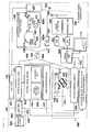
- FIG. 4 is a diagram illustrating the functional configuration of the imaging apparatus for diagnosis 100 which can include an IVUS function and an OCT function (here, a wavelength sweeping-type OCT as an example) in combination.
- An imaging apparatus for diagnosis including the IVUS function and other OCT functions in combination also has the same functional configuration. Therefore, description thereof will be omitted herein.
- the imaging core 220 can include the ultrasonic transceiver 310 inside the distal end of the image core 220.
- the ultrasonic transceiver 310 can transmit ultrasonic waves to biological tissues based on pulse waves transmitted by an ultrasonic signal transceiver 452, receives reflected waves (echoes)of the ultrasonic waves, and transmits the reflected waves to the ultrasonic signal transceiver 452 as an ultrasonic signal via an adapter 402 and a slip ring 451.
- a rotary drive portion side of the slip ring 451 is rotatably driven by a radial scanning motor 405 of a rotary drive device 404.
- a rotation angle of the radial scanning motor 405 is detected by an encoder unit 406.
- the scanning and pull-back unit 102 can include a linear drive device 407, and can regulate the axial operation of the imaging core 220 based on a signal from a signal processing unit 428.
- the ultrasonic signal transceiver 452 can include a transmitting wave circuit and a receiving wave circuit (not illustrated).
- the transmitting wave circuit transmits the pulse waves to the ultrasonic transceiver 310 inside the imaging core 220 based on a control signal transmitted from the signal processing unit 428.
- the receiving wave circuit receives an ultrasonic signal from the ultrasonic transceiver 310 inside the imaging core 220.
- the received ultrasonic signal can be amplified by an amplifier 453, and then is input to and detected by a wave detector 454.
- an A/D converter 455 generates digital data (ultrasonic data) of one line by sampling the ultrasonic signal output from the wave detector 454, for example, at 30.6 MHz by an amount of 200 points. Although 30.6 MHz is used here, this is calculated on the assumption that the sampling of 200 points is performed for a depth of 5 mm when sound velocity is set to 1530 m/sec. Therefore, the sampling frequency is not particularly limited thereto.
- the ultrasonic data in units of lines which is generated by the A/D converter 455 is input to the signal processing unit 428.
- the signal processing unit 428 converts the ultrasonic data into a gray scale, thereby generating an ultrasonic cross-sectional image at each position inside a blood vessel and outputting the ultrasonic cross-sectional image to an LCD monitor 113 at a predetermined frame rate.
- the signal processing unit 428 is connected to a motor control circuit 429, and receives a video synchronization signal of the motor control circuit 429.
- the signal processing unit 428 generates the ultrasonic cross-sectional image in synchronization with the received video synchronization signal.
- the video synchronization signal of the motor control circuit 429 is also transmitted to the rotary drive device 404, and the rotary drive device 404 outputs a drive signal synchronized with the video synchronization signal.
- the above-described processing in the signal processing unit 428 and image processing relating to a user interface in the imaging apparatus for diagnosis 100 can be realized in such a way that a predetermined program causes a computer to execute the processing in the signal processing unit 428.
- the reference numeral 408 represents a wavelength sweeping light source (swept laser), and is one type of an extended-cavity laser which can include an optical fiber 416 which is coupled to a semiconductor optical amplifier (SOA) 415 in a ring shape and a polygon scanning filter (408b).
- SOA semiconductor optical amplifier
- Light output from the SOA 415 proceeds to the optical fiber 416, and enters the polygon scanning filter 408b.
- the light whose wavelength is selected here is amplified by the SOA 415, and is finally output from a coupler 414.
- the polygon scanning filter 408b can select the wavelength in combination with a diffraction grating 412 for diffracting the light and a polygon mirror 409. Specifically, the light diffracted by the diffraction grating 412 can be concentrated on a surface of the polygon mirror 409 by two lenses (410 and 411). In this manner, only the light having a wavelength orthogonal to the polygon mirror 409 returns through the same optical path, and is output from the polygon scanning filter 408b. That is, time sweeping of the wavelength can be performed by rotating the polygon mirror 409.
- a 32-sided mirror can be used for the polygon mirror 409 whose rotation speed can be, for example, approximately 50000 rpm.
- the light of a wavelength sweeping light source 408 which is output from the coupler 414 is incident on one end of a first single mode fiber 440, and is transmitted to the distal end side.
- the first single mode fiber 440 can be optically coupled to a second single mode fiber 445 and a third single mode fiber 444 in an optical coupler 441 located in the middle therebetween. Therefore, the light incident on the first single mode fiber 440 is transmitted by being split into a maximum of three optical paths by the optical coupler 441.
- a fifth single mode fiber 443 of the probe unit 101 can be detachably connected via the adapter 402 to a distal end side of a fourth single mode fiber 442 inside the optical rotary joint (optical coupling unit) 403.
- the light from the wavelength sweeping light source 408 can be transmitted to the fifth single mode fiber 443 which can be inserted into the imaging core 220 and can be rotatably driven.
- the transmitted light is emitted from the optical transceiver 320 of the imaging core 220 to the biological tissues inside the blood vessel while a rotary operation and an axial operation are performed. Then, the reflected light scattered on a surface or inside the biological tissues is partially captured by the optical transceiver 320 of the imaging core 220, and returns to the first single mode fiber 440 side through a rearward optical path. Furthermore, the light is partially transferred to the second single mode fiber 445 side by the optical coupler 441, and is emitted from one end of the second single mode fiber 445. Thereafter, the light is received by an optical detector (for example, a photodiode 424).
- an optical detector for example, a photodiode 424
- the rotary drive unit side of the optical rotary joint 403 can be rotatably driven by the radial scanning motor 405 of the rotary drive device 404.
- an optical path length variable mechanism 432 for finely adjusting an optical path length of reference light can be disposed in the distal end opposite to the optical coupler 441 of the third single mode fiber 444.
- the optical path length variable mechanism 432 includes optical path length changing means for changing an optical path length corresponding to the variations in the length.
- the third single mode fiber 444 and a collimating lens 418 can be disposed on a one-axis stage 422 which is movable in an optical axis direction thereof as illustrated by an arrow 423, thereby forming the optical path length changing means.
- the one-axis stage 422 functions as the optical path length changing means having a variable enough range of the optical path length to absorb the variations in the optical path length of the probe unit 101 when the probe unit 101 is replaced.
- the one-axis stage 422 can also include an adjusting means for adjusting an offset. For example, even when the distal end of the probe unit 101 is not in close contact with the surface of the biological tissues, the one-axis stage can finely change the optical path length. In this manner, the optical path length can be set in a state of interfering with the reflected light from the surface position of the biological tissues.
- Interference light received by the photodiode 424 in this way can be photoelectrically converted, and can be input to a demodulator 426 after being amplified by the amplifier 425.
- the demodulator 426 performs demodulation processing for extracting only a signal portion of the interference light, and an output therefrom is input to the A/D converter 427 as an interference light signal.
- the A/D converter 427 performs sampling on the interference light signal, for example, at 180 MHz by an amount of 2048 points, and generates digital data (interference light data) of one line.
- the reason for setting the sampling frequency to 180 MHz is on the assumption that approximately 90% of wavelength sweeping cycles (12.5 ⁇ sec) is extracted as the digital data of 2048 points, when a repetition frequency of the wavelength sweeping is set to 40 kHz.
- the sampling frequency is not particularly limited thereto.
- the signal processing unit 428 is further connected to a control device of optical path length adjusting means 430.
- the signal processing unit 428 controls a position of the one-axis stage 422 via the control device of optical path length adjusting means 430.
- the processing in the signal processing unit 428 can also be realized in such a way that a predetermined program causes a computer to execute the processing.
- FIG. 5 is a diagram illustrating an example of an examplary user interface 500 displayed on the LCD monitor 113.
- the user interface 500 can include a horizontal cross-sectional image display region 510 for displaying a horizontal cross-sectional image generated by the signal processing unit 428, a vertical cross-sectional image display region 520 for displaying a vertical cross-sectional image generated by the signal processing unit 428, and an operation region 530 for performing various operations on the horizontal cross-sectional image and the vertical cross-sectional image which are respectively displayed on the horizontal cross-sectional image display region 510 and the vertical cross-sectional image display region 520.
- the horizontal cross-sectional image display region 510 can include an OCT cross-sectional image display region 511 for displaying an OCT cross-sectional image (optical cross-sectional image) generated by using an OCT function, and an IVUS cross-sectional image display region 512 for displaying an IVUS cross-sectional image (ultrasonic cross-sectional image) generated by using an IVUS function.
- the vertical cross-sectional image display region 520 displays a vertical cross-sectional image 521 generated based on multiple IVUS cross-sectional images.
- a designator 522 displayed on the vertical cross-sectional image display region 520 is to designate a predetermined position in the axial direction of the vertical cross-sectional image 521.
- the OCT cross-sectional image and the IVUS cross-sectional image at the positions respectively designated by the designator 522 are displayed on the OCT cross-sectional image display region 511 and the IVUS cross-sectional image display region 512 which are described above.
- the operation region 530 can include a horizontal cross-sectional image operation region 540 for operating the horizontal cross-sectional image inside the horizontal cross-sectional image display region 510, a vertical cross-sectional image operation region 550 for operating the vertical cross-sectional image inside the vertical cross-sectional image display region 520, and an image reproduction operation region 560 for continuously displaying (reproducing) the respective horizontal cross-sectional images inside the horizontal cross-sectional image display region 510.
- An "ROI designation” button 541 for designating a region of interest (ROI) in the horizontal cross-sectional image (OCT cross-sectional image and/or IVUS cross-sectional image), an "automatic” button 542 and a “manual” button 543 which can be selected when the "ROI designation” button 541 is pressed down are arranged in the horizontal cross-sectional image operation region 540.
- a process for automatically setting the ROI is performed by using the OCT cross-sectional image displayed on the OCT cross-sectional image display region 511 and the IVUS cross-sectional image displayed on the IVUS cross-sectional image display region 512.
- the ROI automatic setting process will be described in detail later.
- a user can manually set the ROI on either the OCT cross-sectional image of the OCT cross-sectional image display region 511 or the IVUS cross-sectional image of the IVUS cross-sectional image display region 512 by using an operation device such as a mouse or a trackball on the operation panel 112.
- a color mapping process can be performed on biological tissues included in the designated ROI by using a color allocated in advance depending on the hardness of the biological tissues.
- the hardness of the biological tissues can be calculated by using strength and attenuation of the received signal.
- an area of the designated ROI can be calculated.
- a "rewind” button 561, a “stop” button 562, and a “reproduction” button 563 can be arranged in the image reproduction operation region 560. If the "rewind” button 561 is pressed down, the horizontal cross-sectional images displayed on the horizontal cross-sectional image display region 510 can be sequentially switched over to the horizontal cross-sectional images which are older in the generation sequence. That is, the horizontal cross-sectional images when proceeding in the direction opposite to the axial direction are continuously displayed.
- the designator 522 is displayed on the vertical cross-sectional image display region 520, in synchronization with the switching of the horizontal cross-sectional images, the designator 522 is moved in the leftward direction of the user interface 500.
- the horizontal cross-sectional images displayed on the horizontal cross-sectional image display region 510 are sequentially switched over to the horizontal cross-sectional images which are newer in the generation sequence. That is, the horizontal cross-sectional images when proceeding in the axial direction are continuously displayed.
- the designator 522 is displayed on the vertical cross-sectional image display region 520, in synchronization with the switching of the horizontal cross-sectional images, the designator 522 is moved in the rightward direction of the user interface 500.
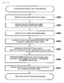
- Step S601 the IVUS cross-sectional image currently displayed on the IVUS cross-sectional image display region 512 is identified.
- Step S602 a blood vessel wall line is extracted from the identified IVUS cross-sectional image.
- the blood vessel wall line is a closed curve obtained by extracting blood vessel wall positions from the IVUS cross-sectional image and connecting the positions as a continuous line segment.
- the blood vessel wall positions are extracted by using a known method.
- the known method for extracting the blood vessel wall positions can include a method for extracting the blood vessel wall positions, in which positions where a value of each pixel data arrayed in the line direction increases steeply are respectively extracted as candidate points of the blood vessel wall positions with regard to each line data configuring the IVUS cross-sectional image, and then the candidate points where a deviation amount between the adjacent candidate points is equal to or greater than a predetermined value are excluded therefrom.
- the blood vessel wall line may generate the closed curve by connecting the extracted blood vessel wall positions using a straight line, or may generate the closed curve by calculating an approximate curve based on the extracted blood vessel wall positions.
- Step S603 the OCT cross-sectional image currently displayed on the OCT cross-sectional image display region 511 is identified.
- Step S604 a blood flow region boundary line is extracted from the identified OCT cross-sectional image.
- the blood flow region boundary line is a closed curve obtained by extracting boundary positions of a blood flow region from the OCT cross-sectional image and connecting the positions as a continuous line segment.
- the boundary positions of the blood flow region are extracted by using a known method.
- the known method for extracting the boundary positions of the blood flow region can include a method for extracting the boundary positions of the blood flow region, in which when a value of each pixel data arrayed in the line direction increases steeply and then decreases slowly, positions where the value increases steeply are respectively extracted as candidate points of the boundary positions of the blood flow region with regard to each line data configuring the OCT cross-sectional image, and then the candidate points where a deviation amount between the adjacent candidate points is equal to or greater than a predetermined value are excluded therefrom.
- the blood flow region boundary line may generate the closed curve by connecting the extracted boundary positions of the blood flow region using a straight line, or may generate the closed curve by calculating an approximate curve based on the extracted boundary positions of the blood flow region.
- a user interface 700 in Fig. 7 indicates a state where the extracted blood vessel wall line is displayed so as to be identifiable by superimposing the blood vessel wall line on the IVUS cross-sectional image displayed on the IVUS cross-sectional image display region 512.
- the user interface 700 can indicate a state where the extracted blood flow region boundary line is displayed so as to be identifiable by superimposing the blood flow region boundary line on the OCT cross-sectional image displayed on the OCT cross-sectional image display region 511.
- Step S605 the IVUS cross-sectional image displayed on the IVUS cross-sectional image display region 512 and the OCT cross-sectional image displayed on the OCT cross-sectional image display region 511 are aligned with each other so that the image centers thereof are coincident with each other.
- the blood vessel wall line and the blood flow region boundary line can be drawn on the same horizontal cross-sectional image (horizontal cross-sectional image of either the IVUS cross-sectional image obtained by extracting the blood vessel wall line or the OCT cross-sectional image obtained by extracting the blood flow region boundary line).
- Step S606 the ROI is set based on the blood vessel wall line and the blood flow region boundary line, which can be drawn on the same horizontal cross-sectional image. Specifically, an outer region of the blood flow region boundary line (region between the blood vessel wall line and the blood flow region boundary line) which is a region surrounded by the blood vessel wall line is set as the ROI.
- Step S607 the set ROI is displayed in a predetermined color so as to be identifiable by superimposing the ROI on the same horizontal cross-sectional image.
- a user interface 800 in Fig. 8 can indicate a state where the blood vessel wall line, the blood flow region boundary line, and the ROI are displayed so as to be identifiable in the IVUS cross-sectional image.
- the imaging apparatus for diagnosis 100 adopts a configuration in which the blood vessel wall line is extracted from the IVUS cross-sectional image by taking advantage of the IVUS characteristics which enable measurement for a very deep region, and in which the blood flow region boundary line is extracted from the OCT cross-sectional image by taking advantage of the OCT characteristics which enable high resolution measurement.
- the blood vessel wall line and the blood flow region boundary line which are the boundary positions within the most important range during diagnosis of the cross-sectional image.
- the blood vessel wall line and the blood flow region boundary line which are respectively extracted from the IVUS cross-sectional image and the OCT cross-sectional image are drawn on the same horizontal cross-sectional image, and the region surrounded by the blood vessel wall line and the blood flow region boundary line is set as the ROI, thereby enabling a user to accurately and quickly set the ROI.
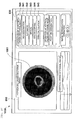
- Fig. 9 illustrates a state where a color mapping process is performed on the ROI set by the ROI automatic setting process depending on the hardness of biological tissues.
- the "color mapping" button 544 of the horizontal cross-sectional image operation region 540 is pressed down in a state where the ROI is displayed (refer to Fig. 8 ), the IVUS cross-sectional image inside the ROI is analyzed, and the hardness of the respective biological tissues inside the ROI is calculated.
- a known method is used as a method of calculating the hardness of the respective biological tissues based on the IVUS cross-sectional image.
- a user interface 900 in Fig. 9 indicates a state where the color mapping process is performed on the ROI by using a color allocated in advance depending on the hardness of the respective biological tissues.
- the imaging apparatus for diagnosis 100 adopts a configuration in which the ROI is set by extracting the blood vessel wall line from the IVUS cross-sectional image, extracting the blood flow region boundary line from the OCT cross-sectional image, and combining both of these with each other.
- the above-described first embodiment adopts a configuration of using the IVUS cross-sectional image when the blood vessel wall line and the blood flow region boundary line which are extracted are drawn on the same horizontal cross-sectional image.
- the disclose may be configured to use the OCT cross-sectional image, or may be configured to use the horizontal cross-sectional image obtained by synthesizing the IVUS cross-sectional image and the OCT cross-sectional image with each other.
- a configuration may be adopted so that the blood vessel wall line and the blood flow region boundary line are respectively drawn on the IVUS cross-sectional image and the OCT cross-sectional image.
- a configuration may be adopted so that a user can select whether the blood vessel wall line and the blood flow region boundary line are to be drawn on any horizontal cross-sectional images between the IVUS cross-sectional image and the OCT cross-sectional image.
- the above-described first embodiment adopts a configuration of displaying the ROI (refer to Fig. 8 ) after the blood vessel wall line and the blood flow region boundary line (refer to Fig. 7 ) are temporarily displayed.
- the image apparatus for diagnosis may adopt a configuration of directly displaying the ROI (refer to Fig. 8 ) when the "automatic" button 541 is pressed down.
- the above-described first embodiment adopts a configuration of automatically displaying the ROI (refer to Fig. 8 ) after the blood vessel wall line and the blood flow region boundary line (refer to Fig. 7 ) are displayed.
- the image apparatus for diagnosis may adopt a configuration of displaying the ROI, only when a user inputs a predetermined instruction after the user confirms whether the blood vessel wall line and the blood flow region boundary line (refer to Fig. 7 ) which are displayed are appropriate or not.
- the image apparatus for diagnosis may adopt a configuration so that correction can be manually added to the blood vessel wall line and the blood flow region boundary line (refer to Fig. 7 ) which are automatically extracted. In this case, a region surrounded by the blood vessel wall line and the blood flow region boundary line after the correction is made manually is set as the ROI.
- the above-described first embodiment adopts a configuration of displaying the color mapping inside the ROI when the color mapping is to be displayed, but the disclosure is not limited thereto.
- Fig. 10 is a diagram illustrating another display example in which the color mapping process is performed by pressing down the "color mapping" button 544.
- a configuration may be adopted in which an annular region 1001 having a predetermined width is displayed outside the ROI so that the color mapping inside the ROI is projected to and displayed on the annular region 1001.
- the hardness of the biological tissues inside the ROI can be relatively easily recognized and can be changed in the circumferential direction.
Landscapes
- Health & Medical Sciences (AREA)
- Life Sciences & Earth Sciences (AREA)
- Engineering & Computer Science (AREA)
- Surgery (AREA)
- General Health & Medical Sciences (AREA)
- Biophysics (AREA)
- Pathology (AREA)
- Veterinary Medicine (AREA)
- Biomedical Technology (AREA)
- Heart & Thoracic Surgery (AREA)
- Medical Informatics (AREA)
- Molecular Biology (AREA)
- Nuclear Medicine, Radiotherapy & Molecular Imaging (AREA)
- Animal Behavior & Ethology (AREA)
- Physics & Mathematics (AREA)
- Public Health (AREA)
- Radiology & Medical Imaging (AREA)
- Vascular Medicine (AREA)
- Hematology (AREA)
- Cardiology (AREA)
- Physiology (AREA)
- Ultra Sonic Daignosis Equipment (AREA)
- Endoscopes (AREA)
- Computer Vision & Pattern Recognition (AREA)
Abstract
Description
- The disclosure here generally relates to an imaging apparatus for diagnosis and an image processing method.
- In the related art, an imaging apparatus for diagnosis has been used for diagnosis of arteriosclerosis, preoperative diagnosis in performing endovascular treatment using a high-performance catheter such as a balloon catheter or a stent, or for confirmation of postoperative results.
- The imaging apparatus for diagnosis can include an intravascular ultrasound (IVUS) diagnosis apparatus and an optical coherence tomography (OCT) diagnosis apparatus, which respectively have different characteristics.
- In addition, an imaging apparatus for diagnosis (imaging apparatus for diagnosis which includes an ultrasonic transceiver capable of transmitting and receiving ultrasonic waves and an optical transceiver capable of transmitting and receiving light) which has an IVUS function and an OCT function in combination has also been proposed (for example, refer to Patent Documents 1 and 2). According to these imaging apparatus for diagnosis, single scanning can generate both a cross-sectional image utilizing IVUS characteristics, which can enable measurement for a very deep region and a cross-sectional image utilizing OCT characteristics, which can enable high resolution measurement.
-
- PTL 1:
JP-A-11-56752 - PTL 2:
JP-T-2010-508973 - When a doctor performs diagnosis using these generated cross-sectional images, it can become important for the doctor to observe a specific range from the outside of a blood flow region to a blood vessel wall in the respective cross-sectional images. The reason can be that distribution, a size, and hardness of biological tissues in the range become important indexes in determining an intravascular state.
- In accordance with an exemplary embodiment, for this reason, if this range can be accurately and quickly set as a region of interest (ROI) in the cross-sectional images, the doctor can not only quickly analyze the range upon diagnosis, but also can obtain an objective analysis result without depending on doctors' different skills.
- In accordance with an exemplary embodiment, the present disclosure can enable a user to accurately and quickly set a region of interest in an imaging apparatus for diagnosis which can generate respective cross-sectional images by using a transceiver capable of transmitting and receiving ultrasonic waves and an optical transceiver capable of transmitting and receiving light.
- In order to achieve the above-described object, an imaging apparatus for diagnosis according to the present invention includes the following configurations.
- That is, there is provided an imaging apparatus for diagnosis which has a transceiver in which an ultrasonic transceiver for transmitting and receiving ultrasonic waves and an optical transceiver for transmitting and receiving light are arranged, and which can generate an ultrasonic cross-sectional image and an optical cross-sectional image inside a blood vessel by transmitting the ultrasonic waves and the light while rotating the transceiver, and by using the reflected wave received by the ultrasonic transceiver and reflected from biological tissues and the reflected light received by the optical transceiver and reflected from the biological tissues while moving the transceiver into a blood vessel in an axial direction. The imaging apparatus for diagnosis can include a first generating means for generating a closed curve using the ultrasonic cross-sectional image at a predetermined position in the axial direction, a second generating means for generating a closed curve using the optical cross-sectional image at the predetermined position, and a setting means for setting a region between the closed curve generated by the first generating means and the closed curve generated by the second generating means as a region of interest in the ultrasonic cross-sectional image or the optical cross-sectional image, in a case where the ultrasonic cross-sectional image and the optical cross-sectional image are aligned and overlapped with each other at the predetermined position.
- In accordance with an exemplary embodiment, a user can accurately and relatively quickly set a region of interest in an imaging apparatus for diagnosis, which can generate respective cross-sectional images by using an ultrasonic transceiver capable of transmitting and receiving ultrasonic waves and an optical transceiver capable of transmitting and receiving light.
- Other characteristics and advantages of the disclosure will become apparent from the following description made with reference to the accompanying drawings. In the accompanying drawings, the same reference numerals are given to the same or similar configuration elements.
- The accompanying drawings are incorporated in the description, configure a part of the description, represent embodiments of the imaging apparatus, and are used to describe principles of the imaging apparatus together with the description.
- [
Fig. 1] Fig. 1 is a view illustrating an external configuration of an imaging apparatus fordiagnosis 100 according to an exemplary embodiment of the disclosure. - [
Fig. 2] Fig. 2 is a view illustrating an overall configuration of a probe unit and a cross-sectional configuration of a distal end portion. - [
Fig. 3] Fig. 3 is a diagram illustrating a cross-sectional configuration of an imaging core and an arrangement of an ultrasonic transceiver and an optical transceiver. - [
Fig. 4] Fig. 4 is a diagram illustrating an exemplary functional configuration of the imaging apparatus fordiagnosis 100. - [
Fig. 5] Fig. 5 is a diagram illustrating an example of a user interface of the imaging apparatus fordiagnosis 100. - [
Fig. 6] Fig. 6 is a flowchart illustrating flow in an automatic setting process for an ROI in the imaging apparatus fordiagnosis 100. - [
Fig. 7] Fig. 7 is a diagram illustrating an example of the exemplary user interface of the imaging apparatus fordiagnosis 100, and a diagram for illustrating a process of automatically setting the ROI. - [
Fig. 8] Fig. 8 is a diagram illustrating an example of the exemplary user interface of the imaging apparatus fordiagnosis 100, and a diagram illustrating a state where the ROI is automatically set. - [
Fig. 9] Fig. 9 is a diagram illustrating an example of the exemplary user interface of the imaging apparatus fordiagnosis 100, and a diagram illustrating an example of an analysis result in the ROI. - [
Fig. 10] Fig. 10 is a diagram illustrating an example of the user interface of the imaging apparatus fordiagnosis 100, and a diagram illustrating an example of an analysis result in the ROI. - Hereinafter, each exemplary embodiment will be described in detail with reference to the accompanying drawings. The embodiments described herein are only specific preferred examples, and thus various technically preferred limitations are imposed thereon. However, the scope of the present invention is not limited to these aspects of the embodiments unless otherwise described below in order to particularly limit the disclosure.
-
Fig. 1 is a view illustrating an external configuration of an imaging apparatus for diagnosis (imaging apparatus for diagnosis which includes an IVUS function and an OCT function) 100 according to an exemplary embodiment of the disclosure. - As illustrated in
Fig. 1 , the imaging apparatus fordiagnosis 100 includes aprobe unit 101, a scanner and pull-back unit 102, and anoperation control device 103. The scanner and pull-back unit 102 and theoperation control device 103 can be connected to each other by asignal line 104 so that various signals can be transmitted. - The
probe unit 101 has an internally inserted imaging core including an ultrasonic transceiver which is directly inserted into a blood vessel, which transmits ultrasonic waves into the blood vessel based on a pulse signal, and which receives reflected waves from the inside of the blood vessel, and an optical transceiver which continuously transmits transmitted light (measurement light) into the blood vessel and which continuously receives reflected light from the inside of the blood vessel. The imaging apparatus fordiagnosis 100 measures an intravascular state by using the imaging core. - The
probe unit 101 is detachably attached to the scanner and pull-back unit 102. A motor incorporated in the scanner and pull-back unit 102 is driven, thereby regulating an intravascular operation in the axial direction and an intravascular operation in the rotation direction of the imaging core which is internally inserted into theprobe unit 101. In addition, the scanner and pull-back unit 102 acquires the reflected wave received by the ultrasonic transceiver and the reflected light received by the optical transceiver, and transmits the reflected wave and the reflected light to theoperation control device 103. - The
operation control device 103 can include a function for inputting various setting values upon each measurement, and a function for processing data obtained by the measurement and for displaying an intravascular cross-sectional image (horizontal cross-sectional image and vertical cross-sectional image). - In the
operation control device 103, thereference numeral 111 represents a main body control unit which generates ultrasonic data based on the reflected waves obtained by the measurement, and which generates an ultrasonic cross-sectional image by processing line data generated based on the ultrasonic data. Furthermore, the mainbody control unit 111 generates interference light data by causing the reflected light obtained by the measurement to interfere with reference light obtained by separating the light from a light source, and generates an optical cross-sectional image by processing the generated line data based on the interference light data. - The reference numeral 111-1 represents a printer and DVD recorder, which prints a processing result in the main
body control unit 111 or stores the processing result as data. Thereference numeral 112 represents an operation panel, and a user inputs various setting values and instructions via theoperation panel 112. Thereference numeral 113 represents an LCD monitor as a display device, which displays a cross-sectional image generated in the mainbody control unit 111. - Next, an overall configuration of the
probe unit 101 and a cross-sectional configuration of a distal end portion will be described with reference toFig. 2 . As illustrated inFig. 2 , theprobe unit 101 is configured to include along catheter sheath 201 to be inserted into the blood vessel and aconnector unit 202 to be arranged on the front side of a user to be operated by the user without being inserted into the blood vessel. Aguidewire lumen tube 203 configuring a guidewire lumen is disposed in the distal end of thecatheter sheath 201. Thecatheter sheath 201 has a lumen which is continuously formed from a connection portion with theguidewire lumen tube 203 to a connection portion with theconnector unit 202. - An
imaging core 220 which internally includes atransceiver 221 in which the ultrasonic transceiver for transmitting and receiving the ultrasonic waves and the optical transceiver for transmitting and receiving the light are arranged, and which includes a coil-shaped drive shaft 222 internally including an electrical signal cable and an optical fiber cable and transmitting rotary drive power for rotating thetransceiver 221 is inserted into the lumen of thecatheter sheath 201 over substantially the entire length of thecatheter sheath 201. - The
connector unit 202 includes asheath connector 202a configured to be integral with a proximal end of thecatheter sheath 201, and adrive shaft connector 202b which is configured to rotatably fix thedrive shaft 222 to the proximal end of thedrive shaft 222. - An
anti-kink protector 211 is disposed in a boundary section between thesheath connector 202a and thecatheter sheath 201, which can help maintain predetermined rigidity, and can help prevent bending (kinking) caused by a rapid change in physical properties. - The proximal end of the
drive shaft connector 202b is detachably attached to the scanner and pull-back unit 102. - Next, the cross-sectional configuration of the distal end portion of the
probe unit 101 will be described. Theimaging core 220 can include ahousing 223 having thetransceiver 221 in which the ultrasonic transceiver for transmitting and receiving the ultrasonic waves and the optical transceiver for transmitting and receiving the light are arranged, and can include thedrive shaft 222 for transmitting the rotary drive power for rotating thehousing 223 is inserted into the lumen of thecatheter sheath 201 over substantially the entire length, thereby forming theprobe unit 101. - The
drive shaft 222 can cause thetransceiver 221 to perform a rotary operation and an axial operation with respect to thecatheter sheath 201, and has a property which can be flexible and can transmit rotation well. For example, thedrive shaft 222 can be configured to have a multiplex and multilayer contact coil formed of a metal wire such as a stainless steel wire. Then, an electric signal cable and an optical fiber cable (optical fiber cable in a single mode) can be arranged inside thedrive shaft 222. - The
housing 223 can have a shape in which a short cylindrical metal pipe partially has a cutout portion, and can be formed by being cut out from a metallic ingot, or can be molded by means of metal powder injection molding (MIM). In addition, anelastic member 231 having a short coil shape can be disposed on the distal end side of thehousing 223. - The
elastic member 231 can be obtained by forming a stainless steel wire into a coil shape. Theelastic member 231 is arranged on the distal end side, which can help prevent theimaging core 220 from being caught on the inside of thecatheter sheath 201 when theimaging core 220 is moved forward and rearward. - The
reference numeral 232 represents a reinforcement coil which is disposed in order to help prevent rapid bending of the distal end portion of thecatheter sheath 201. - The
guidewire lumen tube 203 has a guidewire lumen into which a guidewire can be inserted. Theguidewire lumen tube 203 can be used in receiving the guidewire inserted into the blood vessel in advance and allowing the guidewire to guide thecatheter sheath 201 to a lesion. - Next, a cross-sectional configuration of the
imaging core 220 and an arrangement for the ultrasonic transceiver and the optical transceiver will be described.Fig. 3 is a diagram illustrating the cross-sectional configuration of the imaging core and the arrangement for the ultrasonic transceiver and the optical transceiver. - As illustrated in 3A of
Fig. 3 , thetransceiver 221 arranged inside thehousing 223 can include anultrasonic transceiver 310 and anoptical transceiver 320. Theultrasonic transceiver 310 and theoptical transceiver 320 are respectively arranged along the axial direction on the rotation center axis (on the one-dot chain line in 3A) of thedrive shaft 222. - In both of these, the
ultrasonic transceiver 310 can be arranged on the distal end side of theprobe unit 101, and theoptical transceiver 320 can be arranged on the proximal end side of theprobe unit 101. - In addition, the
ultrasonic transceiver 310 and theoptical transceiver 320 are attached inside thehousing 223 so that an ultrasonic transmitting direction (elevation angle direction) of theultrasonic transceiver 310 and a light transmitting direction (elevation angle direction) of theoptical transceiver 320 are respectively approximately 90° with respect to the axial direction of thedrive shaft 222. It is desirable to attach theultrasonic transceiver 310 can be attached to theoptical transceiver 320 by causing each transmitting direction to be slightly deviated from 90° so as not to receive the reflection on a surface inside the lumen of thecatheter sheath 201. - An
electric signal cable 311 connected to theultrasonic transceiver 310 and anoptical fiber cable 321 connected to theoptical transceiver 320 are arranged inside thedrive shaft 222. Theelectric signal cable 311 can be wound around theoptical fiber cable 321 in a spiral shape. - 3B of
Fig. 3 is a cross-sectional view taken along a plane substantially orthogonal to the rotation center axis at an ultrasonic transmitting and receiving position. As illustrated in 3B ofFig. 3 , when a downward direction from the paper surface is zero degrees, the ultrasonic transmitting and receiving direction (rotation angle direction (also referred to as an azimuth angle direction)) of theultrasonic transceiver 310 is θ degrees. - 3C of
Fig. 3 is a cross-sectional view taken along a plane substantially orthogonal to the rotation center axis at an optical transmitting and receiving position. As illustrated in 3C ofFig. 3 , when the downward direction from the paper surface is zero degrees, the light transmitting and receiving direction (rotation angle direction) of theoptical transceiver 320 is zero degrees. That is, theultrasonic transceiver 310 and theoptical transceiver 320 are arranged so that the ultrasonic transmitting and receiving direction (rotation angle direction) of theultrasonic transceiver 310 and the light transmitting and receiving direction (rotation angle direction) of theoptical transceiver 320 are deviated from each other by θ degrees. - Next, a functional configuration of the imaging apparatus for
diagnosis 100 will be described.Fig. 4 is a diagram illustrating the functional configuration of the imaging apparatus fordiagnosis 100 which can include an IVUS function and an OCT function (here, a wavelength sweeping-type OCT as an example) in combination. An imaging apparatus for diagnosis including the IVUS function and other OCT functions in combination also has the same functional configuration. Therefore, description thereof will be omitted herein. - The
imaging core 220 can include theultrasonic transceiver 310 inside the distal end of theimage core 220. Theultrasonic transceiver 310 can transmit ultrasonic waves to biological tissues based on pulse waves transmitted by anultrasonic signal transceiver 452, receives reflected waves (echoes)of the ultrasonic waves, and transmits the reflected waves to theultrasonic signal transceiver 452 as an ultrasonic signal via anadapter 402 and aslip ring 451. - In the scanner and pull-back
unit 102, a rotary drive portion side of theslip ring 451 is rotatably driven by aradial scanning motor 405 of arotary drive device 404. In addition, a rotation angle of theradial scanning motor 405 is detected by anencoder unit 406. The scanning and pull-backunit 102 can include alinear drive device 407, and can regulate the axial operation of theimaging core 220 based on a signal from asignal processing unit 428. - The
ultrasonic signal transceiver 452 can include a transmitting wave circuit and a receiving wave circuit (not illustrated). The transmitting wave circuit transmits the pulse waves to theultrasonic transceiver 310 inside theimaging core 220 based on a control signal transmitted from thesignal processing unit 428. - In addition, the receiving wave circuit receives an ultrasonic signal from the
ultrasonic transceiver 310 inside theimaging core 220. The received ultrasonic signal can be amplified by anamplifier 453, and then is input to and detected by awave detector 454. - Furthermore, an A/
D converter 455 generates digital data (ultrasonic data) of one line by sampling the ultrasonic signal output from thewave detector 454, for example, at 30.6 MHz by an amount of 200 points. Although 30.6 MHz is used here, this is calculated on the assumption that the sampling of 200 points is performed for a depth of 5 mm when sound velocity is set to 1530 m/sec. Therefore, the sampling frequency is not particularly limited thereto. - The ultrasonic data in units of lines which is generated by the A/
D converter 455 is input to thesignal processing unit 428. Thesignal processing unit 428 converts the ultrasonic data into a gray scale, thereby generating an ultrasonic cross-sectional image at each position inside a blood vessel and outputting the ultrasonic cross-sectional image to anLCD monitor 113 at a predetermined frame rate. - The
signal processing unit 428 is connected to amotor control circuit 429, and receives a video synchronization signal of themotor control circuit 429. Thesignal processing unit 428 generates the ultrasonic cross-sectional image in synchronization with the received video synchronization signal. - In addition, the video synchronization signal of the
motor control circuit 429 is also transmitted to therotary drive device 404, and therotary drive device 404 outputs a drive signal synchronized with the video synchronization signal. - The above-described processing in the
signal processing unit 428 and image processing relating to a user interface in the imaging apparatus for diagnosis 100 (to be described later with reference toFigs. 6 to 10 ) can be realized in such a way that a predetermined program causes a computer to execute the processing in thesignal processing unit 428. - Next, a functional configuration of wavelength sweeping-type OCT will be described with reference to the same drawings. The
reference numeral 408 represents a wavelength sweeping light source (swept laser), and is one type of an extended-cavity laser which can include anoptical fiber 416 which is coupled to a semiconductor optical amplifier (SOA) 415 in a ring shape and a polygon scanning filter (408b). - Light output from the
SOA 415 proceeds to theoptical fiber 416, and enters thepolygon scanning filter 408b. The light whose wavelength is selected here is amplified by theSOA 415, and is finally output from acoupler 414. - The
polygon scanning filter 408b can select the wavelength in combination with adiffraction grating 412 for diffracting the light and apolygon mirror 409. Specifically, the light diffracted by thediffraction grating 412 can be concentrated on a surface of thepolygon mirror 409 by two lenses (410 and 411). In this manner, only the light having a wavelength orthogonal to thepolygon mirror 409 returns through the same optical path, and is output from thepolygon scanning filter 408b. That is, time sweeping of the wavelength can be performed by rotating thepolygon mirror 409. - For example, a 32-sided mirror can be used for the
polygon mirror 409 whose rotation speed can be, for example, approximately 50000 rpm. A wavelength sweeping system in which thepolygon mirror 409 and thediffraction grating 412 can be combined with each other, which can enable high speed and high output wavelength sweeping. - The light of a wavelength sweeping
light source 408 which is output from thecoupler 414 is incident on one end of a firstsingle mode fiber 440, and is transmitted to the distal end side. The firstsingle mode fiber 440 can be optically coupled to a secondsingle mode fiber 445 and a thirdsingle mode fiber 444 in anoptical coupler 441 located in the middle therebetween. Therefore, the light incident on the firstsingle mode fiber 440 is transmitted by being split into a maximum of three optical paths by theoptical coupler 441. - On the further distal end side than the
optical coupler 441 of the firstsingle mode fiber 440, an optical rotary joint (optical coupling unit) 403 which can transmit the light by coupling a non-rotating part (fixed portion) and a rotating part (rotary drive unit) to each other is disposed inside therotary drive device 404. - Furthermore, a fifth
single mode fiber 443 of theprobe unit 101 can be detachably connected via theadapter 402 to a distal end side of a fourthsingle mode fiber 442 inside the optical rotary joint (optical coupling unit) 403. In this manner, the light from the wavelength sweepinglight source 408 can be transmitted to the fifthsingle mode fiber 443 which can be inserted into theimaging core 220 and can be rotatably driven. - The transmitted light is emitted from the
optical transceiver 320 of theimaging core 220 to the biological tissues inside the blood vessel while a rotary operation and an axial operation are performed. Then, the reflected light scattered on a surface or inside the biological tissues is partially captured by theoptical transceiver 320 of theimaging core 220, and returns to the firstsingle mode fiber 440 side through a rearward optical path. Furthermore, the light is partially transferred to the secondsingle mode fiber 445 side by theoptical coupler 441, and is emitted from one end of the secondsingle mode fiber 445. Thereafter, the light is received by an optical detector (for example, a photodiode 424). - The rotary drive unit side of the optical rotary joint 403 can be rotatably driven by the
radial scanning motor 405 of therotary drive device 404. - On the other hand, an optical path length
variable mechanism 432 for finely adjusting an optical path length of reference light can be disposed in the distal end opposite to theoptical coupler 441 of the thirdsingle mode fiber 444. - In order for variations in the length of an
individual probe unit 101 to be absorbed when theprobe unit 101 is replaced and newly used, the optical path lengthvariable mechanism 432 includes optical path length changing means for changing an optical path length corresponding to the variations in the length. - The third
single mode fiber 444 and acollimating lens 418 can be disposed on a one-axis stage 422 which is movable in an optical axis direction thereof as illustrated by anarrow 423, thereby forming the optical path length changing means. - Specifically, the one-
axis stage 422 functions as the optical path length changing means having a variable enough range of the optical path length to absorb the variations in the optical path length of theprobe unit 101 when theprobe unit 101 is replaced. Furthermore, the one-axis stage 422 can also include an adjusting means for adjusting an offset. For example, even when the distal end of theprobe unit 101 is not in close contact with the surface of the biological tissues, the one-axis stage can finely change the optical path length. In this manner, the optical path length can be set in a state of interfering with the reflected light from the surface position of the biological tissues. - The optical path length is finely adjusted by the one-
axis stage 422. The light reflected on amirror 421 via agrating 419 and alens 420 is mixed with the light obtained from the firstsingle mode fiber 440 side by theoptical coupler 441 disposed in the middle of the thirdsingle mode fiber 444, and then is received by thephotodiode 424. - Interference light received by the
photodiode 424 in this way can be photoelectrically converted, and can be input to ademodulator 426 after being amplified by theamplifier 425. Thedemodulator 426 performs demodulation processing for extracting only a signal portion of the interference light, and an output therefrom is input to the A/D converter 427 as an interference light signal. - The A/
D converter 427 performs sampling on the interference light signal, for example, at 180 MHz by an amount of 2048 points, and generates digital data (interference light data) of one line. The reason for setting the sampling frequency to 180 MHz is on the assumption that approximately 90% of wavelength sweeping cycles (12.5 µsec) is extracted as the digital data of 2048 points, when a repetition frequency of the wavelength sweeping is set to 40 kHz. However, the sampling frequency is not particularly limited thereto. - The interference light data in the units of lines which is generated by the A/
D converter 427 is input to thesignal processing unit 428. Thesignal processing unit 428 generates data in a depth direction (line data) by performing frequency resolution on the interference light data using the fast Fourier transform (FFT), and the data is subjected to coordinate transformation. In this manner, an optical cross-sectional image is constructed at each intravascular position, and is output to theLCD monitor 113 at a predetermined frame rate. - The
signal processing unit 428 is further connected to a control device of optical path length adjusting means 430. Thesignal processing unit 428 controls a position of the one-axis stage 422 via the control device of optical path length adjusting means 430. - The processing in the
signal processing unit 428 can also be realized in such a way that a predetermined program causes a computer to execute the processing. - Next, a user interface displayed on the
LCD monitor 113 will be described.Fig. 5 is a diagram illustrating an example of anexamplary user interface 500 displayed on theLCD monitor 113. - As illustrated in
Fig. 5 , theuser interface 500 can include a horizontal cross-sectionalimage display region 510 for displaying a horizontal cross-sectional image generated by thesignal processing unit 428, a vertical cross-sectionalimage display region 520 for displaying a vertical cross-sectional image generated by thesignal processing unit 428, and anoperation region 530 for performing various operations on the horizontal cross-sectional image and the vertical cross-sectional image which are respectively displayed on the horizontal cross-sectionalimage display region 510 and the vertical cross-sectionalimage display region 520. - Furthermore, the horizontal cross-sectional
image display region 510 can include an OCT cross-sectionalimage display region 511 for displaying an OCT cross-sectional image (optical cross-sectional image) generated by using an OCT function, and an IVUS cross-sectionalimage display region 512 for displaying an IVUS cross-sectional image (ultrasonic cross-sectional image) generated by using an IVUS function. - The vertical cross-sectional
image display region 520 displays a verticalcross-sectional image 521 generated based on multiple IVUS cross-sectional images. Adesignator 522 displayed on the vertical cross-sectionalimage display region 520 is to designate a predetermined position in the axial direction of the verticalcross-sectional image 521. The OCT cross-sectional image and the IVUS cross-sectional image at the positions respectively designated by thedesignator 522 are displayed on the OCT cross-sectionalimage display region 511 and the IVUS cross-sectionalimage display region 512 which are described above. - The
operation region 530 can include a horizontal cross-sectionalimage operation region 540 for operating the horizontal cross-sectional image inside the horizontal cross-sectionalimage display region 510, a vertical cross-sectionalimage operation region 550 for operating the vertical cross-sectional image inside the vertical cross-sectionalimage display region 520, and an imagereproduction operation region 560 for continuously displaying (reproducing) the respective horizontal cross-sectional images inside the horizontal cross-sectionalimage display region 510. - An "ROI designation"
button 541 for designating a region of interest (ROI) in the horizontal cross-sectional image (OCT cross-sectional image and/or IVUS cross-sectional image), an "automatic"button 542 and a "manual"button 543 which can be selected when the "ROI designation"button 541 is pressed down are arranged in the horizontal cross-sectionalimage operation region 540. - If the "automatic"
button 542 is pressed down, a process for automatically setting the ROI (ROI automatic setting process) is performed by using the OCT cross-sectional image displayed on the OCT cross-sectionalimage display region 511 and the IVUS cross-sectional image displayed on the IVUS cross-sectionalimage display region 512. The ROI automatic setting process will be described in detail later. - On the other hand, if the "manual"
button 543 is pressed down, a user can manually set the ROI on either the OCT cross-sectional image of the OCT cross-sectionalimage display region 511 or the IVUS cross-sectional image of the IVUS cross-sectionalimage display region 512 by using an operation device such as a mouse or a trackball on theoperation panel 112. - A "color mapping"
button 544 and an "area calculation"button 545 can be further arranged in the horizontal cross-sectionalimage operation region 540. - If the "color mapping"
button 544 is pressed down, a color mapping process can be performed on biological tissues included in the designated ROI by using a color allocated in advance depending on the hardness of the biological tissues. The hardness of the biological tissues can be calculated by using strength and attenuation of the received signal. If the "area calculation"button 545 is pressed down, an area of the designated ROI can be calculated. - A "position designation"
button 551 for displaying thedesignator 522 inside the vertical cross-sectionalimage display region 520 can be arranged in the vertical cross-sectionalimage operation region 550. Thedesignator 522 can be displayed on the vertical cross-sectionalimage display region 520 by pressing down the "position designation"button 551. The horizontal cross-sectional image can be displayed at a desired position in the axial direction on the horizontal cross-sectionalimage display region 510 by using the operation device such as the mouse or the trackball on theoperation panel 112 to move thedesignator 522 in the horizontal direction of theuser interface 500. - A "rewind"
button 561, a "stop"button 562, and a "reproduction"button 563 can be arranged in the imagereproduction operation region 560. If the "rewind"button 561 is pressed down, the horizontal cross-sectional images displayed on the horizontal cross-sectionalimage display region 510 can be sequentially switched over to the horizontal cross-sectional images which are older in the generation sequence. That is, the horizontal cross-sectional images when proceeding in the direction opposite to the axial direction are continuously displayed. When thedesignator 522 is displayed on the vertical cross-sectionalimage display region 520, in synchronization with the switching of the horizontal cross-sectional images, thedesignator 522 is moved in the leftward direction of theuser interface 500. - If the "reproduction"
button 563 is pressed down, the horizontal cross-sectional images displayed on the horizontal cross-sectionalimage display region 510 are sequentially switched over to the horizontal cross-sectional images which are newer in the generation sequence. That is, the horizontal cross-sectional images when proceeding in the axial direction are continuously displayed. When thedesignator 522 is displayed on the vertical cross-sectionalimage display region 520, in synchronization with the switching of the horizontal cross-sectional images, thedesignator 522 is moved in the rightward direction of theuser interface 500. - If the "stop"
button 562 is pressed down, the switching of the horizontal cross-sectional images is stopped at the timing when pressed. - Next, in the
user interface 500, flow of the ROI automatic setting process which is performed by pressing down the "ROI designation"button 541 on the horizontal cross-sectionalimage operation region 540 and further pressing down the "automatic"button 542 will be described. -
Fig. 6 is a flowchart illustrating the flow of the ROI automatic setting process in the imaging apparatus fordiagnosis 100 according to an exemplary embodiment. - In Step S601, the IVUS cross-sectional image currently displayed on the IVUS cross-sectional
image display region 512 is identified. In Step S602, a blood vessel wall line is extracted from the identified IVUS cross-sectional image. The blood vessel wall line is a closed curve obtained by extracting blood vessel wall positions from the IVUS cross-sectional image and connecting the positions as a continuous line segment. The blood vessel wall positions are extracted by using a known method. - For example, the known method for extracting the blood vessel wall positions can include a method for extracting the blood vessel wall positions, in which positions where a value of each pixel data arrayed in the line direction increases steeply are respectively extracted as candidate points of the blood vessel wall positions with regard to each line data configuring the IVUS cross-sectional image, and then the candidate points where a deviation amount between the adjacent candidate points is equal to or greater than a predetermined value are excluded therefrom. The blood vessel wall line may generate the closed curve by connecting the extracted blood vessel wall positions using a straight line, or may generate the closed curve by calculating an approximate curve based on the extracted blood vessel wall positions.
- In Step S603, the OCT cross-sectional image currently displayed on the OCT cross-sectional
image display region 511 is identified. In Step S604, a blood flow region boundary line is extracted from the identified OCT cross-sectional image. The blood flow region boundary line is a closed curve obtained by extracting boundary positions of a blood flow region from the OCT cross-sectional image and connecting the positions as a continuous line segment. The boundary positions of the blood flow region are extracted by using a known method. - For example, the known method for extracting the boundary positions of the blood flow region can include a method for extracting the boundary positions of the blood flow region, in which when a value of each pixel data arrayed in the line direction increases steeply and then decreases slowly, positions where the value increases steeply are respectively extracted as candidate points of the boundary positions of the blood flow region with regard to each line data configuring the OCT cross-sectional image, and then the candidate points where a deviation amount between the adjacent candidate points is equal to or greater than a predetermined value are excluded therefrom. The blood flow region boundary line may generate the closed curve by connecting the extracted boundary positions of the blood flow region using a straight line, or may generate the closed curve by calculating an approximate curve based on the extracted boundary positions of the blood flow region.
- A
user interface 700 inFig. 7 indicates a state where the extracted blood vessel wall line is displayed so as to be identifiable by superimposing the blood vessel wall line on the IVUS cross-sectional image displayed on the IVUS cross-sectionalimage display region 512. In addition, theuser interface 700 can indicate a state where the extracted blood flow region boundary line is displayed so as to be identifiable by superimposing the blood flow region boundary line on the OCT cross-sectional image displayed on the OCT cross-sectionalimage display region 511. - In Step S605, the IVUS cross-sectional image displayed on the IVUS cross-sectional
image display region 512 and the OCT cross-sectional image displayed on the OCT cross-sectionalimage display region 511 are aligned with each other so that the image centers thereof are coincident with each other. In this manner, the blood vessel wall line and the blood flow region boundary line can be drawn on the same horizontal cross-sectional image (horizontal cross-sectional image of either the IVUS cross-sectional image obtained by extracting the blood vessel wall line or the OCT cross-sectional image obtained by extracting the blood flow region boundary line). - In Step S606, the ROI is set based on the blood vessel wall line and the blood flow region boundary line, which can be drawn on the same horizontal cross-sectional image. Specifically, an outer region of the blood flow region boundary line (region between the blood vessel wall line and the blood flow region boundary line) which is a region surrounded by the blood vessel wall line is set as the ROI.
- In Step S607, the set ROI is displayed in a predetermined color so as to be identifiable by superimposing the ROI on the same horizontal cross-sectional image.
- A
user interface 800 inFig. 8 can indicate a state where the blood vessel wall line, the blood flow region boundary line, and the ROI are displayed so as to be identifiable in the IVUS cross-sectional image. - As described above, the imaging apparatus for
diagnosis 100 according to the present embodiment adopts a configuration in which the blood vessel wall line is extracted from the IVUS cross-sectional image by taking advantage of the IVUS characteristics which enable measurement for a very deep region, and in which the blood flow region boundary line is extracted from the OCT cross-sectional image by taking advantage of the OCT characteristics which enable high resolution measurement. - In this manner, it becomes possible to reliably and uniquely extract the blood vessel wall line and the blood flow region boundary line which are the boundary positions within the most important range during diagnosis of the cross-sectional image. In addition, the blood vessel wall line and the blood flow region boundary line which are respectively extracted from the IVUS cross-sectional image and the OCT cross-sectional image are drawn on the same horizontal cross-sectional image, and the region surrounded by the blood vessel wall line and the blood flow region boundary line is set as the ROI, thereby enabling a user to accurately and quickly set the ROI. As a result, when the user performs various analyses using the ROI, as compared to a case of manually setting the ROI, the user can obtain an objective analysis result without depending on the user's skill.
- Next, an analysis example of the ROI set by the above-described ROI automatic setting process will be described.
Fig. 9 illustrates a state where a color mapping process is performed on the ROI set by the ROI automatic setting process depending on the hardness of biological tissues. - If the "color mapping"
button 544 of the horizontal cross-sectionalimage operation region 540 is pressed down in a state where the ROI is displayed (refer toFig. 8 ), the IVUS cross-sectional image inside the ROI is analyzed, and the hardness of the respective biological tissues inside the ROI is calculated. As a method of calculating the hardness of the respective biological tissues based on the IVUS cross-sectional image, a known method is used. - A
user interface 900 inFig. 9 indicates a state where the color mapping process is performed on the ROI by using a color allocated in advance depending on the hardness of the respective biological tissues. - In the example illustrated in
Fig. 9 , a case of pressing down the "color mapping"button 544 has been described. However, for example, when an "area calculation"button 545 is pressed down, the IVUS cross-sectional image inside the ROI is analyzed, and an area inside the ROI is calculated. - As is apparent from the above description, the imaging apparatus for
diagnosis 100 according to the present embodiment adopts a configuration in which the ROI is set by extracting the blood vessel wall line from the IVUS cross-sectional image, extracting the blood flow region boundary line from the OCT cross-sectional image, and combining both of these with each other. - As a result, it becomes possible to accurately and quickly set the ROI.
- The above-described first embodiment adopts a configuration of using the IVUS cross-sectional image when the blood vessel wall line and the blood flow region boundary line which are extracted are drawn on the same horizontal cross-sectional image. However, without being limited thereto, the disclose may be configured to use the OCT cross-sectional image, or may be configured to use the horizontal cross-sectional image obtained by synthesizing the IVUS cross-sectional image and the OCT cross-sectional image with each other. Alternatively, a configuration may be adopted so that the blood vessel wall line and the blood flow region boundary line are respectively drawn on the IVUS cross-sectional image and the OCT cross-sectional image. Alternatively, a configuration may be adopted so that a user can select whether the blood vessel wall line and the blood flow region boundary line are to be drawn on any horizontal cross-sectional images between the IVUS cross-sectional image and the OCT cross-sectional image.
- In addition, the above-described first embodiment adopts a configuration of displaying the ROI (refer to
Fig. 8 ) after the blood vessel wall line and the blood flow region boundary line (refer toFig. 7 ) are temporarily displayed. However, without being limited thereto, the image apparatus for diagnosis may adopt a configuration of directly displaying the ROI (refer toFig. 8 ) when the "automatic"button 541 is pressed down. - In addition, the above-described first embodiment adopts a configuration of automatically displaying the ROI (refer to
Fig. 8 ) after the blood vessel wall line and the blood flow region boundary line (refer toFig. 7 ) are displayed. However, without being limited thereto, the image apparatus for diagnosis may adopt a configuration of displaying the ROI, only when a user inputs a predetermined instruction after the user confirms whether the blood vessel wall line and the blood flow region boundary line (refer toFig. 7 ) which are displayed are appropriate or not. Furthermore, the image apparatus for diagnosis may adopt a configuration so that correction can be manually added to the blood vessel wall line and the blood flow region boundary line (refer toFig. 7 ) which are automatically extracted. In this case, a region surrounded by the blood vessel wall line and the blood flow region boundary line after the correction is made manually is set as the ROI. - The above-described first embodiment adopts a configuration of displaying the color mapping inside the ROI when the color mapping is to be displayed, but the disclosure is not limited thereto.
-
Fig. 10 is a diagram illustrating another display example in which the color mapping process is performed by pressing down the "color mapping"button 544. As illustrated in auser interface 1000 inFig. 10 , a configuration may be adopted in which anannular region 1001 having a predetermined width is displayed outside the ROI so that the color mapping inside the ROI is projected to and displayed on theannular region 1001. According to the color mapping, the hardness of the biological tissues inside the ROI can be relatively easily recognized and can be changed in the circumferential direction. - Without being limited to the above-described embodiment, the present invention can be changed and modified in various ways without departing from the spirit and the scope of the present invention. Therefore, in order to apprise the public of the scope of the present invention, the following Claims are appended herein.
Claims (7)
- An imaging apparatus for diagnosis which has a transceiver in which an ultrasonic transceiver for transmitting and receiving ultrasonic waves and an optical transceiver for transmitting and receiving light are arranged, and which generates an ultrasonic cross-sectional image and an optical cross-sectional image inside a blood vessel by transmitting the ultrasonic waves and the light while rotating the transceiver, and by using the reflected wave received by the ultrasonic transceiver and reflected from biological tissues and the reflected light received by the optical transceiver and reflected from the biological tissues while moving the transceiver into a blood vessel in an axial direction, the apparatus comprising:first generating means for generating a closed curve using the ultrasonic cross-sectional image at a predetermined position in the axial direction;second generating means for generating a closed curve using the optical cross-sectional image at the predetermined position; andsetting means for setting a region between the closed curve generated by the first generating means and the closed curve generated by the second generating means as a region of interest in the ultrasonic cross-sectional image or the optical cross-sectional image, in a case where the ultrasonic cross-sectional image and the optical cross-sectional image are aligned and overlapped with each other at the predetermined position.
- The imaging apparatus for diagnosis according to Claim 1,
wherein the closed curve generated by the first generating means indicates a blood vessel wall, and the closed curve generated by the second generating means indicates a boundary of a blood flow region. - The imaging apparatus for diagnosis according to Claim 2, further comprising:display means for identifiably displaying the region of interest set by the setting means in the ultrasonic cross-sectional image or the optical cross-sectional image by using a predetermined color.
- The imaging apparatus for diagnosis according to Claim 3,
wherein the display means further identifiably displays the closed curve generated by the first generating means and the closed curve generated by the second generating means in the ultrasonic cross-sectional image or the optical cross-sectional image by using a predetermined color. - The imaging apparatus for diagnosis according to Claim 1, further comprising:processing means for processing the region of interest set by the setting means in the ultrasonic cross-sectional image or the optical cross-sectional image.
- An image processing method in an imaging apparatus for diagnosis which has a transceiver in which an ultrasonic transceiver for transmitting and receiving ultrasonic waves and an optical transceiver for transmitting and receiving light are arranged, and which generates an ultrasonic cross-sectional image and an optical cross-sectional image inside a blood vessel by transmitting the ultrasonic waves and the light while rotating the transceiver, and by using the reflected wave received by the ultrasonic transceiver and reflected from biological tissues and the reflected light received by the optical transceiver and reflected from the biological tissues while moving the transceiver into a blood vessel in an axial direction, the method comprising:a first generating process of generating a closed curve using the ultrasonic cross-sectional image at a predetermined position in the axial direction;a second generating process of generating a closed curve using the optical cross-sectional image at the predetermined position; anda setting process of setting a region between the closed curve generated by the first generating means and the closed curve generated by the second generating means as a region of interest in the ultrasonic cross-sectional image or the optical cross-sectional image, in a case where the ultrasonic cross-sectional image and the optical cross-sectional image are aligned and overlapped with each other at the predetermined position.
- A program which causes a computer to execute each process of the image processing method according to Claim 6.
Applications Claiming Priority (1)
| Application Number | Priority Date | Filing Date | Title |
|---|---|---|---|
| PCT/JP2012/005749 WO2014041579A1 (en) | 2012-09-11 | 2012-09-11 | Image diagnosis device and image processing method |
Publications (3)
| Publication Number | Publication Date |
|---|---|
| EP2896372A1 true EP2896372A1 (en) | 2015-07-22 |
| EP2896372A4 EP2896372A4 (en) | 2016-06-01 |
| EP2896372B1 EP2896372B1 (en) | 2018-05-09 |
Family
ID=50277738
Family Applications (1)
| Application Number | Title | Priority Date | Filing Date |
|---|---|---|---|
| EP12884676.3A Active EP2896372B1 (en) | 2012-09-11 | 2012-09-11 | Image diagnosis device and image processing method |
Country Status (4)
| Country | Link |
|---|---|
| US (1) | US20150182192A1 (en) |
| EP (1) | EP2896372B1 (en) |
| JP (1) | JP5981557B2 (en) |
| WO (1) | WO2014041579A1 (en) |
Families Citing this family (14)
| Publication number | Priority date | Publication date | Assignee | Title |
|---|---|---|---|---|
| WO2015171480A1 (en) | 2014-05-06 | 2015-11-12 | Koninklijke Philips N.V. | Devices, systems, and methods for vessel assessment |
| EP4675259A3 (en) | 2015-08-31 | 2026-04-08 | Spryte Medical, Inc. | Imaging system includes imaging probe and delivery devices |
| JP7160935B2 (en) | 2017-11-28 | 2022-10-25 | ジェンテュイティ・リミテッド・ライアビリティ・カンパニー | Imaging system |
| KR102591371B1 (en) * | 2017-12-28 | 2023-10-19 | 삼성메디슨 주식회사 | Ultrasound imaging apparatus and control method for the same |
| WO2019182917A1 (en) | 2018-03-17 | 2019-09-26 | Canon U.S.A., Inc. | Method for virtual device positioning on skin surface in 3d medical image data |
| JP2022500174A (en) | 2018-09-17 | 2022-01-04 | ジェンテュイティ・リミテッド・ライアビリティ・カンパニーGentuity, LLC | Imaging system with optical path |
| WO2020223433A1 (en) | 2019-04-30 | 2020-11-05 | Gentuity, Llc | Imaging probe with fluid pressurization element |
| US12239412B2 (en) | 2019-05-21 | 2025-03-04 | Spryte Medical, Inc. | Systems and methods for OCT-guided treatment of a patient |
| CN110584710B (en) * | 2019-09-03 | 2022-05-31 | 杭州晟视科技有限公司 | Blood flow imaging method and device and storage medium |
| US12239420B2 (en) * | 2019-10-16 | 2025-03-04 | Canon U.S.A., Inc. | Image processing to determine longitudinal orientation and generate tomographic and longitudinal views |
| CN116419705A (en) * | 2020-09-29 | 2023-07-11 | 泰尔茂株式会社 | Information processing device, information processing method, and program |
| JP7623175B2 (en) * | 2021-03-22 | 2025-01-28 | テルモ株式会社 | Computer program, operation method of image processing device, and image processing device |
| CN113096056B (en) * | 2021-04-06 | 2022-04-12 | 全景恒升(北京)科学技术有限公司 | Intravascular image fusion method based on region complementation |
| WO2023132332A1 (en) * | 2022-01-06 | 2023-07-13 | テルモ株式会社 | Computer program, image processing method, and image processing device |
Family Cites Families (8)
| Publication number | Priority date | Publication date | Assignee | Title |
|---|---|---|---|---|
| JP3772002B2 (en) | 1997-08-28 | 2006-05-10 | オリンパス株式会社 | In-subject tomographic imaging system |
| DE10343808B4 (en) * | 2003-09-22 | 2017-06-01 | Siemens Healthcare Gmbh | Medical examination and / or treatment system |
| DE10354496B4 (en) * | 2003-11-21 | 2011-03-31 | Siemens Ag | Medical examination and / or treatment system |
| DE102005037427A1 (en) * | 2005-08-08 | 2007-02-15 | Siemens Ag | Method for recording and evaluating vascular examination data |
| JP2010508973A (en) * | 2006-11-08 | 2010-03-25 | ライトラブ イメージング, インコーポレイテッド | Photo-acoustic imaging device and method |
| CN103222846B (en) * | 2007-01-19 | 2017-04-26 | 桑尼布鲁克健康科学中心 | Scanning mechanisms for imaging probe |
| US10219780B2 (en) * | 2007-07-12 | 2019-03-05 | Volcano Corporation | OCT-IVUS catheter for concurrent luminal imaging |
| JP2010011964A (en) * | 2008-07-02 | 2010-01-21 | Toshiba Corp | Medical image processing apparatus and medical image processing program |
-
2012
- 2012-09-11 JP JP2014535234A patent/JP5981557B2/en active Active
- 2012-09-11 EP EP12884676.3A patent/EP2896372B1/en active Active
- 2012-09-11 WO PCT/JP2012/005749 patent/WO2014041579A1/en not_active Ceased
-
2015
- 2015-03-11 US US14/644,625 patent/US20150182192A1/en not_active Abandoned
Also Published As
| Publication number | Publication date |
|---|---|
| EP2896372B1 (en) | 2018-05-09 |
| JP5981557B2 (en) | 2016-08-31 |
| EP2896372A4 (en) | 2016-06-01 |
| JPWO2014041579A1 (en) | 2016-08-12 |
| WO2014041579A1 (en) | 2014-03-20 |
| US20150182192A1 (en) | 2015-07-02 |
Similar Documents
| Publication | Publication Date | Title |
|---|---|---|
| EP2896372B1 (en) | Image diagnosis device and image processing method | |
| US20150190054A1 (en) | Imaging apparatus for diagnosis and image processing method | |
| EP2832301B1 (en) | Probe and diagnostic imaging device | |
| EP2965682B1 (en) | Diagnostic imaging apparatus and information processing device | |
| US10271818B2 (en) | Image processing apparatus, method of controlling image processing apparatus, program, and storage medium | |
| JP6013502B2 (en) | Image diagnostic apparatus, information processing apparatus, and control method thereof | |
| JPWO2018061780A1 (en) | Control device, image diagnostic device, processing method of control device and program | |
| EP2832300B1 (en) | Tomographic image generation device | |
| JP6125615B2 (en) | Diagnostic imaging apparatus and program | |
| US20150196285A1 (en) | Calibration tool, imaging apparatus for diagnosis, and calibration method of imaging apparatus for diagnosis | |
| JP6637029B2 (en) | Image diagnostic apparatus, operating method thereof, program, and computer-readable storage medium | |
| EP2949259A1 (en) | Image diagnostic device and information processing device and control method therefor, program and computer-readable storage medium | |
| JP6284944B2 (en) | Diagnostic imaging apparatus, operating method thereof, and storage medium | |
| JPWO2013145635A1 (en) | Probe and diagnostic imaging apparatus | |
| JP6100911B2 (en) | Diagnostic imaging apparatus and operating method thereof | |
| JPWO2014049641A1 (en) | Diagnostic imaging apparatus, information processing apparatus, operating method thereof, program, and storage medium | |
| JP6809905B2 (en) | Diagnostic imaging device, operating method and program of diagnostic imaging device | |
| WO2014162366A1 (en) | Image diagnostic device, method for controlling same, program, and computer-readable storage medium |
Legal Events
| Date | Code | Title | Description |
|---|---|---|---|
| PUAI | Public reference made under article 153(3) epc to a published international application that has entered the european phase |
Free format text: ORIGINAL CODE: 0009012 |
|
| 17P | Request for examination filed |
Effective date: 20150227 |
|
| AK | Designated contracting states |
Kind code of ref document: A1 Designated state(s): AL AT BE BG CH CY CZ DE DK EE ES FI FR GB GR HR HU IE IS IT LI LT LU LV MC MK MT NL NO PL PT RO RS SE SI SK SM TR |
|
| AX | Request for extension of the european patent |
Extension state: BA ME |
|
| DAX | Request for extension of the european patent (deleted) | ||
| RA4 | Supplementary search report drawn up and despatched (corrected) |
Effective date: 20160504 |
|
| RIC1 | Information provided on ipc code assigned before grant |
Ipc: A61B 8/12 20060101AFI20160426BHEP Ipc: A61B 5/00 20060101ALI20160426BHEP Ipc: A61B 8/00 20060101ALI20160426BHEP Ipc: A61B 5/026 20060101ALI20160426BHEP Ipc: A61B 8/08 20060101ALI20160426BHEP |
|
| 17Q | First examination report despatched |
Effective date: 20170112 |
|
| GRAP | Despatch of communication of intention to grant a patent |
Free format text: ORIGINAL CODE: EPIDOSNIGR1 |
|
| INTG | Intention to grant announced |
Effective date: 20171221 |
|
| GRAS | Grant fee paid |
Free format text: ORIGINAL CODE: EPIDOSNIGR3 |
|
| GRAA | (expected) grant |
Free format text: ORIGINAL CODE: 0009210 |
|
| AK | Designated contracting states |
Kind code of ref document: B1 Designated state(s): AL AT BE BG CH CY CZ DE DK EE ES FI FR GB GR HR HU IE IS IT LI LT LU LV MC MK MT NL NO PL PT RO RS SE SI SK SM TR |
|
| REG | Reference to a national code |
Ref country code: GB Ref legal event code: FG4D |
|
| REG | Reference to a national code |
Ref country code: CH Ref legal event code: EP Ref country code: AT Ref legal event code: REF Ref document number: 996782 Country of ref document: AT Kind code of ref document: T Effective date: 20180515 |
|
| REG | Reference to a national code |
Ref country code: IE Ref legal event code: FG4D |
|
| REG | Reference to a national code |
Ref country code: DE Ref legal event code: R096 Ref document number: 602012046287 Country of ref document: DE |
|
| REG | Reference to a national code |
Ref country code: FR Ref legal event code: PLFP Year of fee payment: 7 |
|
| REG | Reference to a national code |
Ref country code: NL Ref legal event code: MP Effective date: 20180509 |
|
| REG | Reference to a national code |
Ref country code: LT Ref legal event code: MG4D |
|
| PG25 | Lapsed in a contracting state [announced via postgrant information from national office to epo] |
Ref country code: FI Free format text: LAPSE BECAUSE OF FAILURE TO SUBMIT A TRANSLATION OF THE DESCRIPTION OR TO PAY THE FEE WITHIN THE PRESCRIBED TIME-LIMIT Effective date: 20180509 Ref country code: BG Free format text: LAPSE BECAUSE OF FAILURE TO SUBMIT A TRANSLATION OF THE DESCRIPTION OR TO PAY THE FEE WITHIN THE PRESCRIBED TIME-LIMIT Effective date: 20180809 Ref country code: LT Free format text: LAPSE BECAUSE OF FAILURE TO SUBMIT A TRANSLATION OF THE DESCRIPTION OR TO PAY THE FEE WITHIN THE PRESCRIBED TIME-LIMIT Effective date: 20180509 Ref country code: SE Free format text: LAPSE BECAUSE OF FAILURE TO SUBMIT A TRANSLATION OF THE DESCRIPTION OR TO PAY THE FEE WITHIN THE PRESCRIBED TIME-LIMIT Effective date: 20180509 Ref country code: NO Free format text: LAPSE BECAUSE OF FAILURE TO SUBMIT A TRANSLATION OF THE DESCRIPTION OR TO PAY THE FEE WITHIN THE PRESCRIBED TIME-LIMIT Effective date: 20180809 Ref country code: ES Free format text: LAPSE BECAUSE OF FAILURE TO SUBMIT A TRANSLATION OF THE DESCRIPTION OR TO PAY THE FEE WITHIN THE PRESCRIBED TIME-LIMIT Effective date: 20180509 |
|
| PG25 | Lapsed in a contracting state [announced via postgrant information from national office to epo] |
Ref country code: GR Free format text: LAPSE BECAUSE OF FAILURE TO SUBMIT A TRANSLATION OF THE DESCRIPTION OR TO PAY THE FEE WITHIN THE PRESCRIBED TIME-LIMIT Effective date: 20180810 Ref country code: NL Free format text: LAPSE BECAUSE OF FAILURE TO SUBMIT A TRANSLATION OF THE DESCRIPTION OR TO PAY THE FEE WITHIN THE PRESCRIBED TIME-LIMIT Effective date: 20180509 Ref country code: RS Free format text: LAPSE BECAUSE OF FAILURE TO SUBMIT A TRANSLATION OF THE DESCRIPTION OR TO PAY THE FEE WITHIN THE PRESCRIBED TIME-LIMIT Effective date: 20180509 Ref country code: HR Free format text: LAPSE BECAUSE OF FAILURE TO SUBMIT A TRANSLATION OF THE DESCRIPTION OR TO PAY THE FEE WITHIN THE PRESCRIBED TIME-LIMIT Effective date: 20180509 Ref country code: LV Free format text: LAPSE BECAUSE OF FAILURE TO SUBMIT A TRANSLATION OF THE DESCRIPTION OR TO PAY THE FEE WITHIN THE PRESCRIBED TIME-LIMIT Effective date: 20180509 |
|
| REG | Reference to a national code |
Ref country code: AT Ref legal event code: MK05 Ref document number: 996782 Country of ref document: AT Kind code of ref document: T Effective date: 20180509 |
|
| PG25 | Lapsed in a contracting state [announced via postgrant information from national office to epo] |
Ref country code: DK Free format text: LAPSE BECAUSE OF FAILURE TO SUBMIT A TRANSLATION OF THE DESCRIPTION OR TO PAY THE FEE WITHIN THE PRESCRIBED TIME-LIMIT Effective date: 20180509 Ref country code: AT Free format text: LAPSE BECAUSE OF FAILURE TO SUBMIT A TRANSLATION OF THE DESCRIPTION OR TO PAY THE FEE WITHIN THE PRESCRIBED TIME-LIMIT Effective date: 20180509 Ref country code: EE Free format text: LAPSE BECAUSE OF FAILURE TO SUBMIT A TRANSLATION OF THE DESCRIPTION OR TO PAY THE FEE WITHIN THE PRESCRIBED TIME-LIMIT Effective date: 20180509 Ref country code: CZ Free format text: LAPSE BECAUSE OF FAILURE TO SUBMIT A TRANSLATION OF THE DESCRIPTION OR TO PAY THE FEE WITHIN THE PRESCRIBED TIME-LIMIT Effective date: 20180509 Ref country code: SK Free format text: LAPSE BECAUSE OF FAILURE TO SUBMIT A TRANSLATION OF THE DESCRIPTION OR TO PAY THE FEE WITHIN THE PRESCRIBED TIME-LIMIT Effective date: 20180509 Ref country code: RO Free format text: LAPSE BECAUSE OF FAILURE TO SUBMIT A TRANSLATION OF THE DESCRIPTION OR TO PAY THE FEE WITHIN THE PRESCRIBED TIME-LIMIT Effective date: 20180509 Ref country code: PL Free format text: LAPSE BECAUSE OF FAILURE TO SUBMIT A TRANSLATION OF THE DESCRIPTION OR TO PAY THE FEE WITHIN THE PRESCRIBED TIME-LIMIT Effective date: 20180509 |
|
| REG | Reference to a national code |
Ref country code: DE Ref legal event code: R097 Ref document number: 602012046287 Country of ref document: DE |
|
| PG25 | Lapsed in a contracting state [announced via postgrant information from national office to epo] |
Ref country code: SM Free format text: LAPSE BECAUSE OF FAILURE TO SUBMIT A TRANSLATION OF THE DESCRIPTION OR TO PAY THE FEE WITHIN THE PRESCRIBED TIME-LIMIT Effective date: 20180509 Ref country code: IT Free format text: LAPSE BECAUSE OF FAILURE TO SUBMIT A TRANSLATION OF THE DESCRIPTION OR TO PAY THE FEE WITHIN THE PRESCRIBED TIME-LIMIT Effective date: 20180509 |
|
| PLBE | No opposition filed within time limit |
Free format text: ORIGINAL CODE: 0009261 |
|
| STAA | Information on the status of an ep patent application or granted ep patent |
Free format text: STATUS: NO OPPOSITION FILED WITHIN TIME LIMIT |
|
| 26N | No opposition filed |
Effective date: 20190212 |
|
| PG25 | Lapsed in a contracting state [announced via postgrant information from national office to epo] |
Ref country code: MC Free format text: LAPSE BECAUSE OF FAILURE TO SUBMIT A TRANSLATION OF THE DESCRIPTION OR TO PAY THE FEE WITHIN THE PRESCRIBED TIME-LIMIT Effective date: 20180509 |
|
| REG | Reference to a national code |
Ref country code: CH Ref legal event code: PL |
|
| PG25 | Lapsed in a contracting state [announced via postgrant information from national office to epo] |
Ref country code: SI Free format text: LAPSE BECAUSE OF FAILURE TO SUBMIT A TRANSLATION OF THE DESCRIPTION OR TO PAY THE FEE WITHIN THE PRESCRIBED TIME-LIMIT Effective date: 20180509 |
|
| REG | Reference to a national code |
Ref country code: BE Ref legal event code: MM Effective date: 20180930 |
|
| REG | Reference to a national code |
Ref country code: IE Ref legal event code: MM4A |
|
| PG25 | Lapsed in a contracting state [announced via postgrant information from national office to epo] |
Ref country code: LU Free format text: LAPSE BECAUSE OF NON-PAYMENT OF DUE FEES Effective date: 20180911 |
|
| PG25 | Lapsed in a contracting state [announced via postgrant information from national office to epo] |
Ref country code: IE Free format text: LAPSE BECAUSE OF NON-PAYMENT OF DUE FEES Effective date: 20180911 |
|
| PG25 | Lapsed in a contracting state [announced via postgrant information from national office to epo] |
Ref country code: BE Free format text: LAPSE BECAUSE OF NON-PAYMENT OF DUE FEES Effective date: 20180930 Ref country code: CH Free format text: LAPSE BECAUSE OF NON-PAYMENT OF DUE FEES Effective date: 20180930 Ref country code: LI Free format text: LAPSE BECAUSE OF NON-PAYMENT OF DUE FEES Effective date: 20180930 |
|
| PG25 | Lapsed in a contracting state [announced via postgrant information from national office to epo] |
Ref country code: AL Free format text: LAPSE BECAUSE OF FAILURE TO SUBMIT A TRANSLATION OF THE DESCRIPTION OR TO PAY THE FEE WITHIN THE PRESCRIBED TIME-LIMIT Effective date: 20180509 |
|
| PG25 | Lapsed in a contracting state [announced via postgrant information from national office to epo] |
Ref country code: MT Free format text: LAPSE BECAUSE OF NON-PAYMENT OF DUE FEES Effective date: 20180911 |
|
| PG25 | Lapsed in a contracting state [announced via postgrant information from national office to epo] |
Ref country code: TR Free format text: LAPSE BECAUSE OF FAILURE TO SUBMIT A TRANSLATION OF THE DESCRIPTION OR TO PAY THE FEE WITHIN THE PRESCRIBED TIME-LIMIT Effective date: 20180509 |
|
| PG25 | Lapsed in a contracting state [announced via postgrant information from national office to epo] |
Ref country code: PT Free format text: LAPSE BECAUSE OF FAILURE TO SUBMIT A TRANSLATION OF THE DESCRIPTION OR TO PAY THE FEE WITHIN THE PRESCRIBED TIME-LIMIT Effective date: 20180509 |
|
| PG25 | Lapsed in a contracting state [announced via postgrant information from national office to epo] |
Ref country code: HU Free format text: LAPSE BECAUSE OF FAILURE TO SUBMIT A TRANSLATION OF THE DESCRIPTION OR TO PAY THE FEE WITHIN THE PRESCRIBED TIME-LIMIT; INVALID AB INITIO Effective date: 20120911 Ref country code: CY Free format text: LAPSE BECAUSE OF FAILURE TO SUBMIT A TRANSLATION OF THE DESCRIPTION OR TO PAY THE FEE WITHIN THE PRESCRIBED TIME-LIMIT Effective date: 20180509 Ref country code: MK Free format text: LAPSE BECAUSE OF NON-PAYMENT OF DUE FEES Effective date: 20180509 |
|
| PG25 | Lapsed in a contracting state [announced via postgrant information from national office to epo] |
Ref country code: IS Free format text: LAPSE BECAUSE OF FAILURE TO SUBMIT A TRANSLATION OF THE DESCRIPTION OR TO PAY THE FEE WITHIN THE PRESCRIBED TIME-LIMIT Effective date: 20180909 |
|
| PGFP | Annual fee paid to national office [announced via postgrant information from national office to epo] |
Ref country code: DE Payment date: 20250730 Year of fee payment: 14 |
|
| PGFP | Annual fee paid to national office [announced via postgrant information from national office to epo] |
Ref country code: GB Payment date: 20250731 Year of fee payment: 14 |
|
| PGFP | Annual fee paid to national office [announced via postgrant information from national office to epo] |
Ref country code: FR Payment date: 20250808 Year of fee payment: 14 |