EP2896324A1 - Schiebeanordnung - Google Patents
Schiebeanordnung Download PDFInfo
- Publication number
- EP2896324A1 EP2896324A1 EP14151723.5A EP14151723A EP2896324A1 EP 2896324 A1 EP2896324 A1 EP 2896324A1 EP 14151723 A EP14151723 A EP 14151723A EP 2896324 A1 EP2896324 A1 EP 2896324A1
- Authority
- EP
- European Patent Office
- Prior art keywords
- bracket
- rail
- rack
- slide assembly
- post
- Prior art date
- Legal status (The legal status is an assumption and is not a legal conclusion. Google has not performed a legal analysis and makes no representation as to the accuracy of the status listed.)
- Granted
Links
- 238000005452 bending Methods 0.000 claims 2
- 230000006378 damage Effects 0.000 description 2
- 208000027418 Wounds and injury Diseases 0.000 description 1
- 208000014674 injury Diseases 0.000 description 1
- 230000037431 insertion Effects 0.000 description 1
- 238000003780 insertion Methods 0.000 description 1
- 238000009434 installation Methods 0.000 description 1
- 230000000717 retained effect Effects 0.000 description 1
Images


Classifications
-
- H—ELECTRICITY
- H05—ELECTRIC TECHNIQUES NOT OTHERWISE PROVIDED FOR
- H05K—PRINTED CIRCUITS; CASINGS OR CONSTRUCTIONAL DETAILS OF ELECTRIC APPARATUS; MANUFACTURE OF ASSEMBLAGES OF ELECTRICAL COMPONENTS
- H05K7/00—Constructional details common to different types of electric apparatus
- H05K7/14—Mounting supporting structure in casing or on frame or rack
- H05K7/1485—Servers; Data center rooms, e.g. 19-inch computer racks
- H05K7/1488—Cabinets therefor, e.g. chassis or racks or mechanical interfaces between blades and support structures
- H05K7/1489—Cabinets therefor, e.g. chassis or racks or mechanical interfaces between blades and support structures characterized by the mounting of blades therein, e.g. brackets, rails, trays
-
- A—HUMAN NECESSITIES
- A47—FURNITURE; DOMESTIC ARTICLES OR APPLIANCES; COFFEE MILLS; SPICE MILLS; SUCTION CLEANERS IN GENERAL
- A47B—TABLES; DESKS; OFFICE FURNITURE; CABINETS; DRAWERS; GENERAL DETAILS OF FURNITURE
- A47B88/00—Drawers for tables, cabinets or like furniture; Guides for drawers
- A47B88/40—Sliding drawers; Slides or guides therefor
- A47B88/423—Fastening devices for slides or guides
- A47B88/43—Fastening devices for slides or guides at cabinet side
-
- H—ELECTRICITY
- H05—ELECTRIC TECHNIQUES NOT OTHERWISE PROVIDED FOR
- H05K—PRINTED CIRCUITS; CASINGS OR CONSTRUCTIONAL DETAILS OF ELECTRIC APPARATUS; MANUFACTURE OF ASSEMBLAGES OF ELECTRICAL COMPONENTS
- H05K7/00—Constructional details common to different types of electric apparatus
- H05K7/18—Construction of rack or frame
- H05K7/183—Construction of rack or frame support rails therefor
Definitions
- the present invention relates to a slide assembly, and more particularly, to a slide assembly for installing a chassis to a rack.
- US Patent No. 8,371,454 has disclosed a conventional rack system, which comprises a bracket assembly for installing a chassis to a rack, and is incorporated herein by reference.
- the rack of the conventional rack system has a plurality of holes
- the bracket assembly of the conventional rack system has a bracket, a base and a fastening member, wherein the bracket has a plurality of bracket holes.
- the base is securely connected to the bracket and has multiple connection members located corresponding to the bracket holes.
- the fastening member is pivotally connected to the bracket and includes a resilient leg and a fastening arm which has at least one fastening portion.
- One of the connection members of the base is inserted into one of the holes of the rack, and the fastening portion of the fastening arm is hooked to the rack.
- the conventional rack system lacks of a mechanism for installing the chassis to the rack, such that the chassis may slip off from the rack easily to damage the equipment or cause injury.
- the present invention intends to provide a slide assembly which is able to secure the chassis in the rack.
- the present invention relates to a slide assembly for installing a chassis to a rack, wherein the rack has a first post and a second post, and the first and second posts each have a plurality of holes.
- the chassis has a hook portion.
- the slide assembly of the present invention comprises a first rail having a first end and a second end which is located corresponding to the first end.
- the first rail defines a first slide path longitudinally therein.
- a second rail is slidable relative to the first slide path of the first rail.
- a first bracket has a first end connected adjacent to the first end of the first rail and a second end connected to the first post of the rack.
- a second bracket has a first end connected adjacent to the second end of the first rail and a second end connected to the second post of the rack.
- the first bracket has a bracket board which has a first portion and a second portion.
- the second portion bends and extends from an end of the first portion.
- An engaging member is pivotally connected to the bracket board and has a body portion, a first fastening portion and a second fastening portion.
- the first and second fastening portions are substantially and perpendicularly connected to an end of the body portion.
- the second fastening portion bends and extends from an end of the first fastening portion.
- An engaging space is bounded by the first post and the second fastening portion when the second end of the first bracket is connected to the first post of the rack.
- a resilient member provides a force to the engaging member to maintain the first fastening portion to be connected to the first post of the rack, wherein the hook portion of the chassis is inserted into the engaging space bounded between the first post and the second fastening portion, and contacts the second fastening portion, such that when the chassis is located in the rack, the chassis is not pulled out from the rack.
- a third rail is slidably connected between the first and second rails to form a three-stage slide assembly.
- a back board is fixed adjacent to the first end of the first rail.
- the back board defines a second slide path longitudinally therein.
- the bracket board of the first bracket is movably received by the second slide path of the back board such that the first bracket is longitudinally movable along the back board.
- the first bracket has at least one projecting member which is connected to the second portion of the bracket board.
- the at least one projecting member is inserted into one of the holes of the first post.
- the engaging member comprises an operation portion which is connected to the body portion.
- the bracket board has a slot which is located between the first and second portions thereof. When the operation portion of the engaging member is operated, the slot accommodates the operation portion.
- the present invention also provides a slide assembly which comprises a first rail, a second rail and a third rail.
- the first rail has a first end and a second end which is located corresponding to the first end.
- the third rail is slidably connected between the first and second rails.
- a first bracket is connected adjacent to the first end of the first rail.
- a second bracket is connected adjacent to the second end of the first rail.
- the first bracket has a bracket board which has a first portion and a second portion. The second portion bends and extends from an end of the first portion.
- At least one projecting member is connected to the second portion of the bracket board.
- An engaging member is pivotally connected to the bracket board and has a body portion, a first fastening portion and a second fastening portion.
- the first and second fastening portions are substantially and perpendicularly connected to an end of the body portion.
- the second fastening portion bends and extends from an end of the first fastening portion.
- a resilient member provides a force to the engaging member to maintain the first fastening portion to be positioned close to the at least one projecting member.
- a back board is fixed to the first rail.
- the bracket board is movably connected to the back board so that the first bracket is longitudinally movable along the back board.
- the engaging member comprises an operation portion which is connected to the body portion.
- the bracket board has a slot which is bounded by the first and second portions of the bracket board. When the operation portion of the engaging member is operated, the slot accommodates the operation portion.
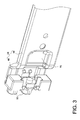
- a preferred embodiment of the present invention comprises a rack 10 and a slide assembly 12.
- the slide assembly 12 is used to install a chassis to the rack 10.
- the rack 10 at least comprises a first post 13 and a second post 14, wherein the first and second posts 13, 14 each have a plurality of holes 16.
- the slide assembly 12 is connected between the first and second posts 13, 14.
- the slide assembly 12 comprises a first rail 18, a second rail 26, a first bracket 28 and a second bracket 30.
- the first rail 18 has a first end 20 and a second end 22 which is located corresponding to the first end 20.
- the first rail 18 defines a first slide path 24 longitudinally therein.
- the second rail 26 is slidable relative to the first slide path 24 of the first rail 18.
- a third rail 29 is slidably connected between the first and second rails 18, 26 to form a three-stage slide assembly to extend the length of the slide assembly 12.
- first bracket 28 is connected adjacent to the first end 20 of the first rail 18, and the other end of the first bracket 28 is adapted to be connected to the first post 13 of the rack 10.
- One end of the second bracket 30 is connected adjacent to the second end 22 of the first rail 18, and the other end of the second bracket 30 is adapted to be connected to the second post 14 of the rack 10.
- the first bracket 28 comprises a bracket board 34, a connecting member 36, at least one projecting member 50 and an engaging member 58.
- the slide assembly 12 further has a back board 32.
- the back board 32 is connected to the first rail 18 such that the first bracket 28 can be connected to the first rail 18 by the back board 32.
- the back board 32 is fixedly connected adjacent to the first end 20 of the first rail 18 and has a top wall 40, a bottom wall 42 and a side wall 38.
- the side wall 38 extends between the top and bottom walls 40, 42 such that a second slide path 44 is bounded by the top wall 40, the bottom wall 42 and the side wall 38, and the bracket board 34 of the first bracket 28 is movably connected to the back board 32 so that the first bracket 28 can move longitudinally along the back board 32.
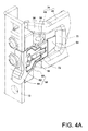
- the bracket board 34 has a first portion 46 and a second portion 48, wherein the second portion 48 bends and extends from one end of the first portion 46.
- the first portion 46 of the bracket board 34 is received by the second slide path 44 of the back board 32 such that the first bracket 28 is longitudinally movable along the back board 32.
- the connecting member 36 has a riveting portion 52, a pivoting portion 54 and a contact portion 56, wherein the connecting member 36 is fixedly connected to the second portion 48 of the bracket board 34 by the riveting portion 52 thereof.
- the at least one projecting member 50 of the firs bracket 28 is longitudinally connected to the second portion 48 of the bracket board 34, such that the bracket board 34 is able to connect one end of the slide assembly 12 to the first post 13 by insertion of the at least one projecting member 50 into one of the holes 16 of the first post 13.
- the second bracket 30 also has at least one projecting member 50 which is adapted to be inserted into one of the holes 16 of the second post 14 to connect the other end of the slide assembly 12 to the second post 14.
- the engaging member 58 can be pivotally connected to a position close to the second portion 48 of the bracket board 34, such as, be pivotally connected to the pivoting portion 54 of the connecting member 36.
- the engaging member 58 comprises a body portion 60, a first fastening portion 62 and a second fastening portion 64, wherein the first and second fastening portions 62, 64 are substantially and perpendicularly connected to one end of the body portion 60, and the second fastening portion 64 bends and extends from one end of the first fastening portion 62, whereby when the first bracket 28 is connected to the first post 13, the first fastening portion 62 contacts the first post 13, and an engaging space 66 is bounded by the first post 13 and the second fastening portion 64.
- the engaging space 66 has a width "D".
- the engaging member 58 further comprises an operation portion 68 which is connected to the body portion 60, and the bracket board 34 has a slot 70 which is bounded by the first and second portions 46, 48 of the bracket board 34.
- the slot 70 can accommodate the operation portion 68.
- the first bracket 28 further comprises a resilient member 72, wherein one end of the resilient member 72 is connected to the engaging member 58, and the other end of the resilient member 72 contacts against the contact portion 56 of the connecting member 36.
- the resilient member 72 provides a force to the engaging member 58 to maintain the first fastening portion 62 to be positioned close to the at least one projecting member 50 and to be securely connected to the first post 13.
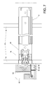
- FIGS. 5A , 5B and 5C show the installation of the first bracket 28 to the first post 13 of the rack 10.
- a force F1 is applied to the operation portion 68 of the engaging member 58 to let the first and second fastening portions 62, 64 of the engaging member 58 be away from the at least one projecting member 50 for a distance
- a force F2 is applied to the bracket board 34 to insert the at least one projecting member 50 into one of the holes 16 of the first post 13 (as shown in FIG. 5B ), and then the forces F1 and F2 are released at the same time (as shown in FIG.
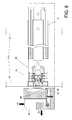
- a chassis 74 has one side thereof connected to the slide assembly 12.
- the chassis 74 has an engaging mechanism 80 which is located corresponding to the second fastening portion 64 of the engaging member 58 of the first bracket 28.
- the engaging mechanism 80 comprises a control portion 82 and a hook portion 84.
Landscapes
- Engineering & Computer Science (AREA)
- Microelectronics & Electronic Packaging (AREA)
- Computer Hardware Design (AREA)
- General Engineering & Computer Science (AREA)
- Drawers Of Furniture (AREA)
Priority Applications (1)
| Application Number | Priority Date | Filing Date | Title |
|---|---|---|---|
| EP14151723.5A EP2896324B1 (de) | 2014-01-20 | 2014-01-20 | Gestell umfassend eine Schiebeanordnung und ein Gehäuse |
Applications Claiming Priority (1)
| Application Number | Priority Date | Filing Date | Title |
|---|---|---|---|
| EP14151723.5A EP2896324B1 (de) | 2014-01-20 | 2014-01-20 | Gestell umfassend eine Schiebeanordnung und ein Gehäuse |
Publications (2)
| Publication Number | Publication Date |
|---|---|
| EP2896324A1 true EP2896324A1 (de) | 2015-07-22 |
| EP2896324B1 EP2896324B1 (de) | 2016-11-16 |
Family
ID=49958323
Family Applications (1)
| Application Number | Title | Priority Date | Filing Date |
|---|---|---|---|
| EP14151723.5A Active EP2896324B1 (de) | 2014-01-20 | 2014-01-20 | Gestell umfassend eine Schiebeanordnung und ein Gehäuse |
Country Status (1)
| Country | Link |
|---|---|
| EP (1) | EP2896324B1 (de) |
Cited By (3)
| Publication number | Priority date | Publication date | Assignee | Title |
|---|---|---|---|---|
| US9545153B2 (en) * | 2015-05-15 | 2017-01-17 | King Slide Works Co., Ltd. | Slide rail assembly |
| US20170020024A1 (en) * | 2015-07-15 | 2017-01-19 | King Slide Works Co., Ltd. | Slide rail assembly |
| US10595435B2 (en) * | 2018-06-01 | 2020-03-17 | Gslide Corporation | Server rail and server rack mounting structure |
Citations (6)
| Publication number | Priority date | Publication date | Assignee | Title |
|---|---|---|---|---|
| US20010040203A1 (en) * | 2000-03-17 | 2001-11-15 | Brock Patty J. | Computer server mounting apparatus |
| US20040079712A1 (en) * | 2002-10-28 | 2004-04-29 | Mayer David W. | Tool-less rack mounting system |
| DE202004018376U1 (de) * | 2003-12-30 | 2005-01-20 | King Slide Works Co., Ltd., Lu-Chu Hsiang | Trägerpositionierungsstruktur für Gleitschienen |
| US20110233355A1 (en) * | 2010-03-24 | 2011-09-29 | Hong Fu Jin Precision Industry (Shenzhen) Co., Ltd. | Mounting appratus for slide rail |
| US20110290746A1 (en) * | 2010-05-27 | 2011-12-01 | Hon Hai Precision Industry Co., Ltd. | Slide assembly |
| US8371454B2 (en) | 2008-09-25 | 2013-02-12 | King Slide Works Co., Ltd. | Bracket assembly for a rack |
-
2014
- 2014-01-20 EP EP14151723.5A patent/EP2896324B1/de active Active
Patent Citations (6)
| Publication number | Priority date | Publication date | Assignee | Title |
|---|---|---|---|---|
| US20010040203A1 (en) * | 2000-03-17 | 2001-11-15 | Brock Patty J. | Computer server mounting apparatus |
| US20040079712A1 (en) * | 2002-10-28 | 2004-04-29 | Mayer David W. | Tool-less rack mounting system |
| DE202004018376U1 (de) * | 2003-12-30 | 2005-01-20 | King Slide Works Co., Ltd., Lu-Chu Hsiang | Trägerpositionierungsstruktur für Gleitschienen |
| US8371454B2 (en) | 2008-09-25 | 2013-02-12 | King Slide Works Co., Ltd. | Bracket assembly for a rack |
| US20110233355A1 (en) * | 2010-03-24 | 2011-09-29 | Hong Fu Jin Precision Industry (Shenzhen) Co., Ltd. | Mounting appratus for slide rail |
| US20110290746A1 (en) * | 2010-05-27 | 2011-12-01 | Hon Hai Precision Industry Co., Ltd. | Slide assembly |
Cited By (4)
| Publication number | Priority date | Publication date | Assignee | Title |
|---|---|---|---|---|
| US9545153B2 (en) * | 2015-05-15 | 2017-01-17 | King Slide Works Co., Ltd. | Slide rail assembly |
| US20170020024A1 (en) * | 2015-07-15 | 2017-01-19 | King Slide Works Co., Ltd. | Slide rail assembly |
| US9848702B2 (en) * | 2015-07-15 | 2017-12-26 | King Slide Works Co., Ltd. | Slide rail assembly |
| US10595435B2 (en) * | 2018-06-01 | 2020-03-17 | Gslide Corporation | Server rail and server rack mounting structure |
Also Published As
| Publication number | Publication date |
|---|---|
| EP2896324B1 (de) | 2016-11-16 |
Similar Documents
| Publication | Publication Date | Title |
|---|---|---|
| US20150201754A1 (en) | Slide assembly | |
| EP3661340B1 (de) | Klammervorrichtung | |
| EP3197252A1 (de) | Gleitschienenanordnung und führungsmechanismus davon | |
| EP2632240A2 (de) | Anschlussvorrichtung für einen Kabelverwaltungsarm und Schubanordnung | |
| US20130233980A1 (en) | Connection device for cable management arm and slide assembly | |
| US9161625B2 (en) | Slide rail assembly | |
| US9237671B2 (en) | Slide rail assembly for rack system | |
| US9848702B2 (en) | Slide rail assembly | |
| US9474182B1 (en) | Slide rail assembly | |
| US20140265786A1 (en) | Support structure for support bracket and rail | |
| US20150296982A1 (en) | Mounting device for drawer system | |
| EP2896324B1 (de) | Gestell umfassend eine Schiebeanordnung und ein Gehäuse | |
| CN104735945A (zh) | 滑轨装置 | |
| EP2560470A2 (de) | Schiebeanordnung mit Positionierungsvorrichtung | |
| EP2893838B1 (de) | Schiebeanordnung mit einem verstellbaren Beschlag | |
| EP2870897A1 (de) | Schienenanordnung | |
| EP1720227A1 (de) | Befestigungsvorrichtung zum Befestigen einer Dose an einer Leiter | |
| CN105375338A (zh) | 电气设备 | |
| EP3076774A1 (de) | Schienenanordnung | |
| EP2540191B1 (de) | Tragemechanismus für Schiebeführung | |
| EP3045074A1 (de) | Gleitschienenanordnung und Montagevorrichtung davon | |
| EP2813161A1 (de) | Befestigungsvorrichtung für eine Schiebeanordnung | |
| US8245989B2 (en) | Device support structure | |
| EP2777431A1 (de) | Stützstruktur für Tragkonsole und -schiene | |
| US20090163060A1 (en) | Apparatus and Method for Retaining Option Card in a Computer System |
Legal Events
| Date | Code | Title | Description |
|---|---|---|---|
| PUAI | Public reference made under article 153(3) epc to a published international application that has entered the european phase |
Free format text: ORIGINAL CODE: 0009012 |
|
| 17P | Request for examination filed |
Effective date: 20141028 |
|
| AK | Designated contracting states |
Kind code of ref document: A1 Designated state(s): AL AT BE BG CH CY CZ DE DK EE ES FI FR GB GR HR HU IE IS IT LI LT LU LV MC MK MT NL NO PL PT RO RS SE SI SK SM TR |
|
| AX | Request for extension of the european patent |
Extension state: BA ME |
|
| 17Q | First examination report despatched |
Effective date: 20160408 |
|
| RIC1 | Information provided on ipc code assigned before grant |
Ipc: A47B 88/04 20060101AFI20160425BHEP Ipc: H05K 7/14 20060101ALI20160425BHEP Ipc: H05K 7/18 20060101ALI20160425BHEP |
|
| GRAP | Despatch of communication of intention to grant a patent |
Free format text: ORIGINAL CODE: EPIDOSNIGR1 |
|
| INTG | Intention to grant announced |
Effective date: 20160609 |
|
| GRAS | Grant fee paid |
Free format text: ORIGINAL CODE: EPIDOSNIGR3 |
|
| GRAA | (expected) grant |
Free format text: ORIGINAL CODE: 0009210 |
|
| AK | Designated contracting states |
Kind code of ref document: B1 Designated state(s): AL AT BE BG CH CY CZ DE DK EE ES FI FR GB GR HR HU IE IS IT LI LT LU LV MC MK MT NL NO PL PT RO RS SE SI SK SM TR |
|
| REG | Reference to a national code |
Ref country code: GB Ref legal event code: FG4D |
|
| REG | Reference to a national code |
Ref country code: DE Ref legal event code: R079 Ref document number: 602014004796 Country of ref document: DE Free format text: PREVIOUS MAIN CLASS: A47B0088040000 Ipc: A47B0088400000 |
|
| REG | Reference to a national code |
Ref country code: CH Ref legal event code: EP |
|
| REG | Reference to a national code |
Ref country code: IE Ref legal event code: FG4D |
|
| REG | Reference to a national code |
Ref country code: AT Ref legal event code: REF Ref document number: 845051 Country of ref document: AT Kind code of ref document: T Effective date: 20161215 |
|
| REG | Reference to a national code |
Ref country code: DE Ref legal event code: R096 Ref document number: 602014004796 Country of ref document: DE |
|
| REG | Reference to a national code |
Ref country code: NL Ref legal event code: FP |
|
| PG25 | Lapsed in a contracting state [announced via postgrant information from national office to epo] |
Ref country code: LV Free format text: LAPSE BECAUSE OF FAILURE TO SUBMIT A TRANSLATION OF THE DESCRIPTION OR TO PAY THE FEE WITHIN THE PRESCRIBED TIME-LIMIT Effective date: 20161116 |
|
| REG | Reference to a national code |
Ref country code: LT Ref legal event code: MG4D |
|
| REG | Reference to a national code |
Ref country code: AT Ref legal event code: MK05 Ref document number: 845051 Country of ref document: AT Kind code of ref document: T Effective date: 20161116 |
|
| PG25 | Lapsed in a contracting state [announced via postgrant information from national office to epo] |
Ref country code: SE Free format text: LAPSE BECAUSE OF FAILURE TO SUBMIT A TRANSLATION OF THE DESCRIPTION OR TO PAY THE FEE WITHIN THE PRESCRIBED TIME-LIMIT Effective date: 20161116 Ref country code: NO Free format text: LAPSE BECAUSE OF FAILURE TO SUBMIT A TRANSLATION OF THE DESCRIPTION OR TO PAY THE FEE WITHIN THE PRESCRIBED TIME-LIMIT Effective date: 20170216 Ref country code: LT Free format text: LAPSE BECAUSE OF FAILURE TO SUBMIT A TRANSLATION OF THE DESCRIPTION OR TO PAY THE FEE WITHIN THE PRESCRIBED TIME-LIMIT Effective date: 20161116 |
|
| PG25 | Lapsed in a contracting state [announced via postgrant information from national office to epo] |
Ref country code: PT Free format text: LAPSE BECAUSE OF FAILURE TO SUBMIT A TRANSLATION OF THE DESCRIPTION OR TO PAY THE FEE WITHIN THE PRESCRIBED TIME-LIMIT Effective date: 20170316 Ref country code: AT Free format text: LAPSE BECAUSE OF FAILURE TO SUBMIT A TRANSLATION OF THE DESCRIPTION OR TO PAY THE FEE WITHIN THE PRESCRIBED TIME-LIMIT Effective date: 20161116 Ref country code: ES Free format text: LAPSE BECAUSE OF FAILURE TO SUBMIT A TRANSLATION OF THE DESCRIPTION OR TO PAY THE FEE WITHIN THE PRESCRIBED TIME-LIMIT Effective date: 20161116 Ref country code: FI Free format text: LAPSE BECAUSE OF FAILURE TO SUBMIT A TRANSLATION OF THE DESCRIPTION OR TO PAY THE FEE WITHIN THE PRESCRIBED TIME-LIMIT Effective date: 20161116 Ref country code: HR Free format text: LAPSE BECAUSE OF FAILURE TO SUBMIT A TRANSLATION OF THE DESCRIPTION OR TO PAY THE FEE WITHIN THE PRESCRIBED TIME-LIMIT Effective date: 20161116 Ref country code: BE Free format text: LAPSE BECAUSE OF NON-PAYMENT OF DUE FEES Effective date: 20170131 Ref country code: RS Free format text: LAPSE BECAUSE OF FAILURE TO SUBMIT A TRANSLATION OF THE DESCRIPTION OR TO PAY THE FEE WITHIN THE PRESCRIBED TIME-LIMIT Effective date: 20161116 Ref country code: PL Free format text: LAPSE BECAUSE OF FAILURE TO SUBMIT A TRANSLATION OF THE DESCRIPTION OR TO PAY THE FEE WITHIN THE PRESCRIBED TIME-LIMIT Effective date: 20161116 |
|
| PG25 | Lapsed in a contracting state [announced via postgrant information from national office to epo] |
Ref country code: RO Free format text: LAPSE BECAUSE OF FAILURE TO SUBMIT A TRANSLATION OF THE DESCRIPTION OR TO PAY THE FEE WITHIN THE PRESCRIBED TIME-LIMIT Effective date: 20161116 Ref country code: CZ Free format text: LAPSE BECAUSE OF FAILURE TO SUBMIT A TRANSLATION OF THE DESCRIPTION OR TO PAY THE FEE WITHIN THE PRESCRIBED TIME-LIMIT Effective date: 20161116 Ref country code: EE Free format text: LAPSE BECAUSE OF FAILURE TO SUBMIT A TRANSLATION OF THE DESCRIPTION OR TO PAY THE FEE WITHIN THE PRESCRIBED TIME-LIMIT Effective date: 20161116 Ref country code: DK Free format text: LAPSE BECAUSE OF FAILURE TO SUBMIT A TRANSLATION OF THE DESCRIPTION OR TO PAY THE FEE WITHIN THE PRESCRIBED TIME-LIMIT Effective date: 20161116 Ref country code: SK Free format text: LAPSE BECAUSE OF FAILURE TO SUBMIT A TRANSLATION OF THE DESCRIPTION OR TO PAY THE FEE WITHIN THE PRESCRIBED TIME-LIMIT Effective date: 20161116 |
|
| REG | Reference to a national code |
Ref country code: DE Ref legal event code: R097 Ref document number: 602014004796 Country of ref document: DE |
|
| PG25 | Lapsed in a contracting state [announced via postgrant information from national office to epo] |
Ref country code: BE Free format text: LAPSE BECAUSE OF FAILURE TO SUBMIT A TRANSLATION OF THE DESCRIPTION OR TO PAY THE FEE WITHIN THE PRESCRIBED TIME-LIMIT Effective date: 20161116 Ref country code: BG Free format text: LAPSE BECAUSE OF FAILURE TO SUBMIT A TRANSLATION OF THE DESCRIPTION OR TO PAY THE FEE WITHIN THE PRESCRIBED TIME-LIMIT Effective date: 20170216 Ref country code: IT Free format text: LAPSE BECAUSE OF FAILURE TO SUBMIT A TRANSLATION OF THE DESCRIPTION OR TO PAY THE FEE WITHIN THE PRESCRIBED TIME-LIMIT Effective date: 20161116 Ref country code: SM Free format text: LAPSE BECAUSE OF FAILURE TO SUBMIT A TRANSLATION OF THE DESCRIPTION OR TO PAY THE FEE WITHIN THE PRESCRIBED TIME-LIMIT Effective date: 20161116 |
|
| REG | Reference to a national code |
Ref country code: CH Ref legal event code: PL |
|
| PLBE | No opposition filed within time limit |
Free format text: ORIGINAL CODE: 0009261 |
|
| STAA | Information on the status of an ep patent application or granted ep patent |
Free format text: STATUS: NO OPPOSITION FILED WITHIN TIME LIMIT |
|
| PG25 | Lapsed in a contracting state [announced via postgrant information from national office to epo] |
Ref country code: MC Free format text: LAPSE BECAUSE OF FAILURE TO SUBMIT A TRANSLATION OF THE DESCRIPTION OR TO PAY THE FEE WITHIN THE PRESCRIBED TIME-LIMIT Effective date: 20161116 |
|
| 26N | No opposition filed |
Effective date: 20170817 |
|
| REG | Reference to a national code |
Ref country code: FR Ref legal event code: ST Effective date: 20170929 |
|
| PG25 | Lapsed in a contracting state [announced via postgrant information from national office to epo] |
Ref country code: FR Free format text: LAPSE BECAUSE OF NON-PAYMENT OF DUE FEES Effective date: 20170131 Ref country code: CH Free format text: LAPSE BECAUSE OF NON-PAYMENT OF DUE FEES Effective date: 20170131 Ref country code: LI Free format text: LAPSE BECAUSE OF NON-PAYMENT OF DUE FEES Effective date: 20170131 |
|
| REG | Reference to a national code |
Ref country code: IE Ref legal event code: MM4A |
|
| PG25 | Lapsed in a contracting state [announced via postgrant information from national office to epo] |
Ref country code: LU Free format text: LAPSE BECAUSE OF NON-PAYMENT OF DUE FEES Effective date: 20170120 Ref country code: SI Free format text: LAPSE BECAUSE OF FAILURE TO SUBMIT A TRANSLATION OF THE DESCRIPTION OR TO PAY THE FEE WITHIN THE PRESCRIBED TIME-LIMIT Effective date: 20161116 |
|
| PG25 | Lapsed in a contracting state [announced via postgrant information from national office to epo] |
Ref country code: IE Free format text: LAPSE BECAUSE OF NON-PAYMENT OF DUE FEES Effective date: 20170120 |
|
| PG25 | Lapsed in a contracting state [announced via postgrant information from national office to epo] |
Ref country code: MT Free format text: LAPSE BECAUSE OF NON-PAYMENT OF DUE FEES Effective date: 20170120 |
|
| PG25 | Lapsed in a contracting state [announced via postgrant information from national office to epo] |
Ref country code: HU Free format text: LAPSE BECAUSE OF FAILURE TO SUBMIT A TRANSLATION OF THE DESCRIPTION OR TO PAY THE FEE WITHIN THE PRESCRIBED TIME-LIMIT; INVALID AB INITIO Effective date: 20140120 |
|
| PG25 | Lapsed in a contracting state [announced via postgrant information from national office to epo] |
Ref country code: CY Free format text: LAPSE BECAUSE OF FAILURE TO SUBMIT A TRANSLATION OF THE DESCRIPTION OR TO PAY THE FEE WITHIN THE PRESCRIBED TIME-LIMIT Effective date: 20161116 |
|
| PG25 | Lapsed in a contracting state [announced via postgrant information from national office to epo] |
Ref country code: MK Free format text: LAPSE BECAUSE OF FAILURE TO SUBMIT A TRANSLATION OF THE DESCRIPTION OR TO PAY THE FEE WITHIN THE PRESCRIBED TIME-LIMIT Effective date: 20161116 |
|
| PG25 | Lapsed in a contracting state [announced via postgrant information from national office to epo] |
Ref country code: TR Free format text: LAPSE BECAUSE OF FAILURE TO SUBMIT A TRANSLATION OF THE DESCRIPTION OR TO PAY THE FEE WITHIN THE PRESCRIBED TIME-LIMIT Effective date: 20161116 |
|
| PG25 | Lapsed in a contracting state [announced via postgrant information from national office to epo] |
Ref country code: GR Free format text: LAPSE BECAUSE OF FAILURE TO SUBMIT A TRANSLATION OF THE DESCRIPTION OR TO PAY THE FEE WITHIN THE PRESCRIBED TIME-LIMIT Effective date: 20161116 |
|
| PG25 | Lapsed in a contracting state [announced via postgrant information from national office to epo] |
Ref country code: AL Free format text: LAPSE BECAUSE OF FAILURE TO SUBMIT A TRANSLATION OF THE DESCRIPTION OR TO PAY THE FEE WITHIN THE PRESCRIBED TIME-LIMIT Effective date: 20161116 Ref country code: IS Free format text: LAPSE BECAUSE OF FAILURE TO SUBMIT A TRANSLATION OF THE DESCRIPTION OR TO PAY THE FEE WITHIN THE PRESCRIBED TIME-LIMIT Effective date: 20170316 |
|
| PGFP | Annual fee paid to national office [announced via postgrant information from national office to epo] |
Ref country code: NL Payment date: 20240110 Year of fee payment: 11 |
|
| PGFP | Annual fee paid to national office [announced via postgrant information from national office to epo] |
Ref country code: DE Payment date: 20240112 Year of fee payment: 11 Ref country code: GB Payment date: 20240108 Year of fee payment: 11 |