EP2895903B1 - Contact etanche en position deconnectee pour connecteur - Google Patents
Contact etanche en position deconnectee pour connecteur Download PDFInfo
- Publication number
- EP2895903B1 EP2895903B1 EP13785612.6A EP13785612A EP2895903B1 EP 2895903 B1 EP2895903 B1 EP 2895903B1 EP 13785612 A EP13785612 A EP 13785612A EP 2895903 B1 EP2895903 B1 EP 2895903B1
- Authority
- EP
- European Patent Office
- Prior art keywords
- contact
- ferrule
- seal
- connector
- sealing means
- Prior art date
- Legal status (The legal status is an assumption and is not a legal conclusion. Google has not performed a legal analysis and makes no representation as to the accuracy of the status listed.)
- Active
Links
Images
Classifications
-
- G—PHYSICS
- G02—OPTICS
- G02B—OPTICAL ELEMENTS, SYSTEMS OR APPARATUS
- G02B6/00—Light guides; Structural details of arrangements comprising light guides and other optical elements, e.g. couplings
- G02B6/24—Coupling light guides
- G02B6/36—Mechanical coupling means
- G02B6/38—Mechanical coupling means having fibre to fibre mating means
- G02B6/3807—Dismountable connectors, i.e. comprising plugs
- G02B6/3833—Details of mounting fibres in ferrules; Assembly methods; Manufacture
- G02B6/3847—Details of mounting fibres in ferrules; Assembly methods; Manufacture with means preventing fibre end damage, e.g. recessed fibre surfaces
- G02B6/3849—Details of mounting fibres in ferrules; Assembly methods; Manufacture with means preventing fibre end damage, e.g. recessed fibre surfaces using mechanical protective elements, e.g. caps, hoods, sealing membranes
-
- G—PHYSICS
- G02—OPTICS
- G02B—OPTICAL ELEMENTS, SYSTEMS OR APPARATUS
- G02B6/00—Light guides; Structural details of arrangements comprising light guides and other optical elements, e.g. couplings
- G02B6/24—Coupling light guides
- G02B6/36—Mechanical coupling means
- G02B6/38—Mechanical coupling means having fibre to fibre mating means
- G02B6/3807—Dismountable connectors, i.e. comprising plugs
- G02B6/3869—Mounting ferrules to connector body, i.e. plugs
-
- G—PHYSICS
- G02—OPTICS
- G02B—OPTICAL ELEMENTS, SYSTEMS OR APPARATUS
- G02B6/00—Light guides; Structural details of arrangements comprising light guides and other optical elements, e.g. couplings
- G02B6/24—Coupling light guides
- G02B6/36—Mechanical coupling means
- G02B6/38—Mechanical coupling means having fibre to fibre mating means
- G02B6/3807—Dismountable connectors, i.e. comprising plugs
- G02B6/381—Dismountable connectors, i.e. comprising plugs of the ferrule type, e.g. fibre ends embedded in ferrules, connecting a pair of fibres
- G02B6/3826—Dismountable connectors, i.e. comprising plugs of the ferrule type, e.g. fibre ends embedded in ferrules, connecting a pair of fibres characterised by form or shape
Definitions
- the present invention relates to connectors, in particular optical connectors.
- the present invention relates to optical connectors comprising contacts which retain sealing properties when they are disconnected in order to prevent materials and / or dust from damaging them.
- the solution found for the individual contacts is of the following type: the seal is fixed and the ferrule or part of the contact slides inside this seal.
- patent US 6,357,929 illustrates a connector in which the sealing at the contact level is maintained regardless of the position of said contact (connected or disconnected) so that such a mechanical connection is permanent with the negative consequences mentioned above.
- An aim of the invention is therefore to improve the known contacts and connectors.
- an object of the invention is to provide a contact, for example a contact for an optical connector, having simple and effective means for ensuring its tightness in the disconnected position.
- Another aim of the present invention is to provide a sealed contact guaranteeing compliance in the plugged-in / connected position.
- the aim is to ensure, for an individual contact, a seal in the disconnected state and a certain mobility in the connected state.
- the system developed to overcome the identified problems and achieve the aims of the invention is to make the seal and the ferrule integral and to allow the seal to move with the latter to have an effect or not depending on the effective position of the ferrule (corresponding in connected or disconnected state).
- the seal becomes a movable part which no longer hinders compliance in the plugged / connected position.
- the invention proposes an assembly of a seal (for example of the O-ring type) on an optical alignment ferrule making it possible to create a seal in the unconnected rest position.
- Said seal is linked to the ferrule and moves with the latter when removing said ferrule when plugging in the complete connector, making it possible not to degrade the precision of the alignment of the ferrule when it is inserted into the socket. alignment occurring when the complete system is connected.
- a disconnected and compliant sealed contact connected which comprises at least one contact body in which are positioned a transmission means held in a support at the end of which a ferrule is placed, a seal between the ferrule and the means of transmission being achieved by filling with sealant, in which a sealing means is provided between the ferrule and the contact body, said means creating a seal between the ferrule and the contact body when the contact is disconnected and allowing a mechanical isolation of the ferrule from the contact body when the contact is connected.
- the sealing means is a seal mounted on the ferrule.
- the seal is an O-ring.
- the sealing means is a flexible element added to the ferrule by overmolding.
- the sealing means is a flexible element added to the contact body by overmolding.
- the contact surfaces between the ferrule and the contact body at the level of the sealing means are flat or have complementary shapes.
- the contact surfaces between the ferrule, the contact body and the flexible element are flat or have complementary shapes.
- the transmission means is an optical fiber.
- the sealing means is epoxy
- the invention relates to a connector comprising at least one contact as defined in the present application.
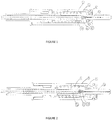
- the contact comprises a contact body 1 in which are positioned an optical fiber 11 held in a buffer 13 at the end of which (contact side) is a ferrule 3.
- the seal between the ferrule 3 and the optical fiber 11 is guaranteed by a filling of sealant (for example epoxy) 12 around the optical fiber 11 and the buffer of said fiber 13 or by other equivalent means.
- a means forming a seal 2 for example an O-Ring, is positioned on the ferrule 3 and makes it possible to create a tight barrier between said ferrule 3 and the contact body 1.
- the seal 2 is compressed between the body of contact 1 and ferrule 3 using the compressive force produced by a spring 4.
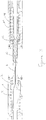
- the ferrule 3 moves back relative to the contact body 1 under the action of the opposite contact (for example an identical ferrule) to take its plugged-in position illustrated in figure 2 .
- the seal-forming means 2 keeps its initial position on the ferrule 3 due to a slight tightening of said seal 2 on said ferrule 3. Consequently, the seal 2 never worsens the dimensioned play around the ferrule which allows to said ferrule 3 to be mechanically isolated from the contact body 1.
- This mechanical insulation also called compliance, is, due to the relative movement of the seal 2, never hampered by said seal 2
- the ferrule 3 is isolated from any stress, vibrations, etc. which would be applied to the connector, which makes it possible to ensure good contact in the connection, for example ferrule against ferrule and therefore optical fiber against optical fiber.
- Such a ferrule-to-ferrule connected state is illustrated in the figure 3 .
- the contact on the left side is for example that described with reference to figures 1 and 2 above and its (connected) state therefore corresponds to the figure 2 , where seal 2 has moved with ferrule 3.
- the contact shown on the right side of the figure 3 is typically identical to that on the left side in that it comprises the same original means, namely in particular a body 11, a means forming a seal 12, a ferrule 13 and a pressure means such as a spring 14.
- the two contacts have in this state a compliance and are mechanically isolated from the connector which carries them.
- the use of a spring 4, 14 as illustrated advantageously makes it possible to improve the contact of the ferrules 3, 13 end to end since the two springs 4, 14 exert their return force against one another. They therefore make it possible to exert a certain pressure on the contact surfaces of the ferrules 3, 13, or even to maintain good contact whatever the external influences undergone by the connector (movements, vibrations, etc.).
- seal 2 is illustrated in the form of an O-ring but another equivalent seal is entirely possible.
- a joint of rectangular section It is also possible to envisage using complementary shapes between the ferrule 3 and the inside of the contact body to further improve the seal instead of the flat surfaces illustrated in the figures. figures 1 and 2 .
- the effect of the seal 2 can be achieved by covering the ferrule by overmolding a flexible element or by other covering process.
- the effect of the seal 2 can be achieved by covering the contact by overmolding a flexible element or another covering process.
- the spring 4 can also be replaced by another equivalent means fulfilling the same function.
- the contact according to the present invention is preferably an optical contact using an optical fiber.
- the principles of the present invention are applicable to other types of contact, for example electrical contacts.
Landscapes
- Physics & Mathematics (AREA)
- General Physics & Mathematics (AREA)
- Optics & Photonics (AREA)
- Mechanical Coupling Of Light Guides (AREA)
- Connector Housings Or Holding Contact Members (AREA)
Description
- La présente invention concerne les connecteurs, en particulier les connecteurs optiques.
- Plus précisément, la présente invention concerne des connecteurs optiques comportant des contacts qui conservent des propriétés d'étanchéité lorsqu'ils sont déconnectés afin d'éviter que des matières et/ou des poussières ne les abîment.
- Un exemple typique d'un tel contact/connecteur est donné dans le brevet
US 6,357,929 . - D'autres exemples de tels contacts/connecteurs sont commercialisés par les sociétés Glenair® ou Souriau® et sont décrits dans les pages internet aux adresses suivantes http://www.glenair.com/contacts/pdf/fiber optic 181 043.pdf http://www.glenair.com/contacts/pdf/fiber optic 181 050.pdf http://www.glenair.com/contacts/qpl_and_commercial_high_performance_fiber_optic_t ermini.htm http://www.souriau.com/fileadmin/Souriau/product_pdf/ELIO-Fiber-Optic-Contact.pdf
- Actuellement, il existe dans le domaine de la connectique fibre optique des contacts étanches déconnectés avec des O rings au niveau des ferrules. Cependant le fonctionnement de ces contacts peut être affecté par le joint O-Ring. En effet, le principe de base d'un contact fibre optique dans l'état de la technique est d'isoler mécaniquement les ferrules et la douille d'alignement du reste du connecteur.
- Dans des connecteurs connus la solution trouvée pour les contacts individuels est du type suivant: le joint est fixe et la ferrule ou une partie du contact coulisse à l'intérieur de ce joint.
- L'étanchéité est donc garantie quelle que soit la position de la ferrule. Cependant le fait d'avoir une liaison mécanique permanente sur toute la course du contact péjore sa compliance en position enfichée (c'est-à-dire en position connectée) et donc par conséquence sa stabilité et résistance aux différentes contraintes mécaniques (vibrations etc).
- A titre d'exemple, le brevet
US 6,357,929 illustre un connecteur dans lequel l'étanchéité au niveau du contact est maintenue quelle que soit la position dudit contact (connecté ou déconnecté) de sorte qu'une telle liaison mécanique est permanente avec les conséquences négatives mentionnées ci-dessus. - Un but de l'invention est par conséquent d'améliorer les contacts et les connecteurs connus.
- Plus précisément, un but de l'invention est de proposer un contact, par exemple un contact pour connecteur optique, possédant des moyens simples et efficaces pour assurer son étanchéité en position déconnectée.
- Un autre but de la présente invention est la réalisation d'un contact étanche garantissant une compliance en position enfichée/connectée.
- En particulier, selon l'invention, l'on s'est rendu compte qu'une étanchéité n'est pas nécessaire, voire même superflue, sur le contact en position enfichée (c'est-à-dire connectée) car l'étanchéité est assurée en fait par le boitier/assemblage fiche-connecteur dans cette configuration. Maintenir une étanchéité locale en position enfichée/connectée est donc inutile, voire désavantageux si l'on veut permettre une certaine mobilité des pièces (par exemple pour éviter une influence de vibrations externes), une fois la connexion effectuée, ce que l'on dénomme ici la "compliance".
- En d'autres termes, l'on cherche à assurer pour un contact individuel une étanchéité en état déconnecté et une certaine mobilité en état connecté.
- Le système développé pour surmonter les problèmes identifiés et atteindre les buts de l'invention est de rendre solidaires le joint et la ferrule et de permettre au joint de bouger avec cette dernière pour avoir un effet ou non selon la position effective de la ferrule (correspondant à l'état connecté ou déconnecté).
- De cette façon, le joint devient une partie mobile qui n'entrave plus la compliance en position enfichée/connectée.
- Par voie de conséquence l'étanchéité individuelle du contact n'est plus garantie en position enfichée, mais une telle étanchéité n'est concrètement pas nécessaire puisqu'elle est assurée au niveau du connecteur. Par contre grâce à l'utilisation de la force d'un ressort ou d'un autre moyen équivalent pour la compression du joint, le contact en position désenfichée devient étanche.
- De plus, l'utilisation d'un moyen de type ressort permet d'améliorer le contact de l'extrémité de la ferrule ce qui a un effet bénéfique pour le connecteur, comme on le comprendra dans la suite de la présente description.
- Dans un mode d'exécution, l'invention propose un assemblage d'un joint (par exemple de type O-ring) sur une ferrule d'alignement optique permettant de créer une étanchéité en position de repos non connecté. Ledit joint est lié à la ferrule et se déplace avec celle-ci lors du retrait de ladite ferrule lors de l'enfichage du connecteur complet, permettant de ne pas dégrader la précision de l'alignement de la ferrule lors de son insertion dans la douille d'alignement intervenant lors de la connexion du système complet.
- L'invention porte sur un contact étanche déconnecté et compliant connecté, qui comprend au moins un corps de contact dans lequel sont positionnés un moyen de transmission tenu dans un support au bout duquel une ferrule est placée, une étanchéité entre la ferrule et le moyen de transmission étant réalisée par un remplissage de produit de scellement, dans lequel un moyen d'étanchéité est prévu entre la ferrule et le corps de contact, ledit moyen créant une étanchéité entre la ferrule et le corps de contact lorsque le contact est déconnecté et permettant une isolation mécanique de la ferrule par rapport au corps de contact lorsque le contact et connecté.
- Dans un mode d'exécution, le moyen d'étanchéité est un joint monté sur la ferrule.
- Dans un mode d'exécution, le joint est un O-ring.
- Dans un mode d'exécution, le moyen d'étanchéité est un élément souple ajouté sur la ferrule par surmoulage.
- Dans un mode d'exécution, le moyen d'étanchéité est un élément souple ajouté sur le corps de contact par surmoulage.
- Dans un mode d'exécution, les surfaces de contact entre la ferrule et le corps de contact au niveau du moyen d'étanchéité sont planes ou ont des formes complémentaires.
- Dans un mode d'exécution, les surfaces de contact entre la ferrule, le corps de contact et l'élément souple sont planes ou ont des formes complémentaires.
- Dans un mode d'exécution, le moyen de transmission est une fibre optique.
- Dans un mode d'exécution, le moyen de scellement est de l'epoxy.
- Dans un mode d'exécution, l'invention concerne un connecteur comprenant au moins un contact tel que défini dans la présente demande.
- L'invention sera mieux comprise par la description de modes d'exécution et des figures qui s'y rapportent dans lesquelles
- La
figure 1 illustre en coupe un mode d'exécution d'un connecteur en état déconnecté; - La
figure 2 illustre en coupe un mode d'exécution d'un connecteur en état connecté. - La
figure 3 illustre en coupe un mode d'exécution de deux connecteur en état connecté l'un à l'autre. -
Figure 1 : Position au repos (désenfiché/déconnecté) - Dans cette position le contact est considéré comme étanche selon les principes de la présente invention.
- Plus précisément, le contact comprend un corps de contact 1 dans lequel sont positionnés une fibre optique 11 tenue dans un buffer 13 au bout duquel (côté contact) se situe une ferrule 3. L'étanchéité entre la ferrule 3 et la fibre optique 11 est garantie par un remplissage de produit de scellement (par exemple de l'epoxy) 12 autour de la fibre optique 11 et du buffer de ladite fibre 13 ou par d'autres moyens équivalents.
- Un moyen formant joint 2, par exemple un O-Ring, est positionné sur la ferrule 3 et permet de créer une barrière étanche entre ladite ferrule 3 et le corps de contact 1. Dans ce but, le joint 2 est comprimé entre le corps de contact 1 et la ferrule 3 en utilisant la force de compression produite par un ressort 4.
- Dans cet état "déconnecté", le contact est par conséquent étanche selon les principes exposés dans la présente demande.
-
Figure 2 : Position sous contrainte (enfiché/connecté) - Lorsque que l'on réalise un enfichage du contact, la ferrule 3 recule relativement au corps de contact 1 sous l'action du contact opposé (par exemple une ferrule identique) pour prendre sa position enfichée illustrée dans la
figure 2 . - Dans cette position, le moyen formant joint 2 garde sa position initiale sur la ferrule 3 du fait d'un léger serrement dudit joint 2 sur ladite ferrule 3. En conséquence, le joint 2 ne péjore jamais le jeu dimensionné autour de la ferrule qui permet à ladite ferrule 3 d'être isolée mécaniquement du corps de contact 1. Cette isolation mécanique également appelée compliance n'est, du fait du mouvement relatif du joint 2, jamais entravée par ledit joint 2
- Ainsi, la ferrule 3 est isolée de toute contrainte, vibrations etc qui seraient appliqués au connecteur ce qui permet d'assurer un bon contact dans la connection par exemple ferrule contre ferrule et par conséquent fibre optique contre fibre optique.
- Un tel état connecté ferrule contre ferrule est illustré dans la
figure 3 . Le contact du côté gauche est par exemple celui décrit en référence auxfigures 1 et 2 ci-dessus et son état (connecté) correspond donc à lafigure 2 , où le joint 2 s'est déplacé avec le ferrule 3. Le contact illustré sur le côté droit de lafigure 3 est typiquement identique à celui du côté gauche en ce sens qu'il comprend les mêmes moyens originaux, à savoir notamment un corps 11, un moyen formant joint 12, une ferrule 13 et un moyen de pression comme un ressort 14. Comme on le comprend aisément de la description ci-dessus, quand les deux contacts sont connectés l'un à l'autre, les deux ferrules 3 et 13 s'appliquent bout-à-bout l'une contre l'autre et, par ce contacte se repoussent mutuellement de sorte que les joints 2, 12 reculent également et n'assurent plus l'étanchéité. - Toutefois, selon les effets obtenus par la présente invention, les deux contacts possèdent dans cet état une compliance et sont isolés mécaniquement du connecteur qui les porte. De plus, l'utilisation d'un ressort 4, 14 tel qu'illustré permet de façon avantageuse d'améliorer le contact des ferrules 3, 13 bout à bout puisque les deux ressorts 4, 14 exercent leur force de rappel l'un contre l'autre. Ils permettent donc d'exercer une certaine pression sur les surfaces de contact des ferrules 3, 13, voir de maintenir un bon contact quelles que soit les influences extérieures subies par le connecteur (mouvements, vibrations etc.).
- Les modes d'exécution décrits sont des exemples illustratifs qui ne doivent pas être interprétés de façon limitative. Des variations sont possibles en faisant appel à des moyens équivalents pour obtenir le même résultat.
- Par exemple le joint 2 est illustré sous forme de O-ring mais un autre joint équivalent est tout à fait envisageable. Par exemple on peut imaginer un joint de section rectangulaire. On peut également envisager de faire appel à des formes complémentaires entre la ferrule 3 et l'intérieur du corps de contact pour améliorer encore l'étanchéité à la place des surfaces planes illustrées dans les
figures 1 et 2 . - Dans un autre mode d'exécution, l'effet du joint 2 peut être réalisé par recouvrement de la ferrule par surmoulage d'un élément souple ou autre procédé de recouvrement.
- Dans un autre mode d'exécution, l'effet du joint 2 peut être réalisé par recouvrement du contact par surmoulage d'un élément souple ou autre procédé de recouvrement.
- Ces deux modes d'exécution peuvent être combinés pour prévoir un élément souple surmoulé sur la ferrule et sur le corps de contact, avec des surfaces de contact planes ou complémentaires.
- Le ressort 4 peut lui aussi être remplacé par un autre moyen équivalent remplissant la même fonction.
- Le contact selon la présente invention est de préférence un contact optique utilisant une fibre optique. Toutefois, les principes de la présente invention sont applicables à d'autres types de contact, par exemple des contacts électriques.
Claims (10)
- Contact de connecteur, comprenant au moins un corps de contact (1), un moyen de transmission (11), un support (13) du moyen de transmission (11), ledit support (13) comprenant à son bout une ferrule (3), un ressort appliquant une force de compression sur la ferrule et un produit de scellement (12) réalisant une étanchéité entre la ferrule (3) et le moyen de transmission (11), caractérisé en ce que le contact comprend un moyen d'étanchéité (2) souple entre la ferrule (3) et le corps de contact (1) de manière à créer une étanchéité entre la ferrule (3) et le corps de contact (1) lorsque le contact est déconnecté et la ferrule soumise à la force du ressort (4) et lorsque le contact est connecté, la ferrule (3) est isolée de toute contrainte mécanique par rapport au corps de contact, ladite isolation mécanique n'étant pas entravée par ledit moyen d'étanchéité (2).
- Contact selon la revendication 1, dans lequel le moyen d'étanchéité comprend un joint (2) monté sur la ferrule (3).
- Contact selon la revendication 2, dans lequel le joint est un O-ring (2).
- Contact selon la revendication 1, dans lequel le moyen d'étanchéité est un élément ajouté sur la ferrule (3) par surmoulage.
- Contact selon l'une des revendications 1 ou 4, dans lequel le moyen d'étanchéité comprend un élément souple ajouté sur le corps de contact (1) par surmoulage.
- Contact selon la revendication 1, dans lequel les surfaces de contact entre la ferrule (3) et le corps de contact (1) au niveau du moyen d'étanchéité sont planes ou ont des formes complémentaires.
- Contact selon la revendication 4 ou 5, dans lequel les surfaces de contact entre la ferrule (3), le corps de contact (1) et l'élément souple sont planes ou ont des formes complémentaires.
- Contact selon l'une des revendications précédentes, dans lequel le moyen de transmission (11) est une fibre optique.
- Contact selon l'une des revendications précédentes, dans lequel le moyen de scellement (12) est de l'epoxy.
- Connecteur comprenant au moins un contact tel que défini dans l'une des revendications précédentes.
Applications Claiming Priority (2)
| Application Number | Priority Date | Filing Date | Title |
|---|---|---|---|
| CH01657/12A CH706931A1 (fr) | 2012-09-12 | 2012-09-12 | Contact étanche en position déconnectée pour connecteur. |
| PCT/IB2013/056832 WO2014041450A1 (fr) | 2012-09-12 | 2013-08-23 | Contact etanche en position deconnectee pour connecteur |
Publications (2)
| Publication Number | Publication Date |
|---|---|
| EP2895903A1 EP2895903A1 (fr) | 2015-07-22 |
| EP2895903B1 true EP2895903B1 (fr) | 2021-02-17 |
Family
ID=49515415
Family Applications (1)
| Application Number | Title | Priority Date | Filing Date |
|---|---|---|---|
| EP13785612.6A Active EP2895903B1 (fr) | 2012-09-12 | 2013-08-23 | Contact etanche en position deconnectee pour connecteur |
Country Status (6)
| Country | Link |
|---|---|
| US (1) | US9599777B2 (fr) |
| EP (1) | EP2895903B1 (fr) |
| CH (1) | CH706931A1 (fr) |
| HK (1) | HK1207688A1 (fr) |
| IL (1) | IL237419B (fr) |
| WO (1) | WO2014041450A1 (fr) |
Families Citing this family (3)
| Publication number | Priority date | Publication date | Assignee | Title |
|---|---|---|---|---|
| CN114488416A (zh) | 2020-08-27 | 2022-05-13 | 华为技术有限公司 | 光纤连接器插头、光纤适配器、连接器组件及通信设备 |
| DE102021111848B4 (de) | 2021-05-06 | 2026-05-13 | Odu Gmbh & Co. Kg | Steckervorrichtung, Steckverbinder und Anschlusskabel |
| US20260023222A1 (en) * | 2024-07-22 | 2026-01-22 | Corning Research & Development Corporation | Hollow-core optical fiber connector with one or more ferrule seals |
Citations (1)
| Publication number | Priority date | Publication date | Assignee | Title |
|---|---|---|---|---|
| US20010014197A1 (en) * | 2000-01-06 | 2001-08-16 | Silverio De Marchi | Plug part for an optical plug-and-socket connection and method for its assembly |
Family Cites Families (10)
| Publication number | Priority date | Publication date | Assignee | Title |
|---|---|---|---|---|
| GB1450760A (en) * | 1975-06-24 | 1976-09-29 | Standard Telephones Cables Ltd | Optical fibre multiway connector |
| US4190316A (en) * | 1978-02-02 | 1980-02-26 | The Deutsch Company | Lens connector for optical fibers |
| US4516829A (en) * | 1982-05-12 | 1985-05-14 | International Telephone & Telegraph Corporation | Fiber optic contact retention assembly |
| US5732175A (en) * | 1997-01-31 | 1998-03-24 | Litecom, Inc. | Connecting system for fiber optic termination |
| US6305849B1 (en) | 1999-02-09 | 2001-10-23 | Fiber Systems International | Multi-channel fiber optic connector |
| US7641395B2 (en) * | 2004-06-22 | 2010-01-05 | Halliburton Energy Serives, Inc. | Fiber optic splice housing and integral dry mate connector system |
| US7806599B2 (en) * | 2007-05-04 | 2010-10-05 | Illum Technologies, Inc. | Super miniature, single fiber optical interconnect system with parallel slider push-push type insertion/withdrawal mechanism and method for using same |
| EP2278367B1 (fr) * | 2008-04-28 | 2016-07-27 | Adamant Kogyo Co., Ltd. | Logement pour connecteur optique et connecteur optique |
| JP5857968B2 (ja) * | 2010-10-29 | 2016-02-10 | アダマンド株式会社 | 光ファイバコネクタ部品及びこの光ファイバコネクタ部品を備えた光ファイバコネクタ |
| US8636425B2 (en) * | 2011-03-15 | 2014-01-28 | Adc Telecommunications, Inc. | Fiber optic connector |
-
2012
- 2012-09-12 CH CH01657/12A patent/CH706931A1/fr unknown
-
2013
- 2013-08-23 EP EP13785612.6A patent/EP2895903B1/fr active Active
- 2013-08-23 US US14/422,994 patent/US9599777B2/en not_active Expired - Fee Related
- 2013-08-23 HK HK15108382.2A patent/HK1207688A1/xx unknown
- 2013-08-23 WO PCT/IB2013/056832 patent/WO2014041450A1/fr not_active Ceased
-
2015
- 2015-02-25 IL IL237419A patent/IL237419B/en active IP Right Grant
Patent Citations (1)
| Publication number | Priority date | Publication date | Assignee | Title |
|---|---|---|---|---|
| US20010014197A1 (en) * | 2000-01-06 | 2001-08-16 | Silverio De Marchi | Plug part for an optical plug-and-socket connection and method for its assembly |
Also Published As
| Publication number | Publication date |
|---|---|
| IL237419A0 (en) | 2015-04-30 |
| US9599777B2 (en) | 2017-03-21 |
| CH706931A1 (fr) | 2014-03-14 |
| IL237419B (en) | 2019-07-31 |
| EP2895903A1 (fr) | 2015-07-22 |
| WO2014041450A1 (fr) | 2014-03-20 |
| US20150212280A1 (en) | 2015-07-30 |
| HK1207688A1 (en) | 2016-02-05 |
Similar Documents
| Publication | Publication Date | Title |
|---|---|---|
| AU2014415442B2 (en) | Connecting member and optical fibre connector | |
| EP2569665A1 (fr) | Dispositif de raccordement de tubes de protection d'un cable a fibres optiques, tronçon d'un circuit de transmission optique comportant un tel dispositif et element d'etancheite pour un tel dispositif | |
| EP1621905B1 (fr) | Connecteur pour fibre optique | |
| EP2793063B1 (fr) | Adaptateur avec cage de maintien pour un connecteur multi-contacts et connecteur multi-contacts associé | |
| EP3789803A1 (fr) | Ensemble pour l'assemblage de fibre optique avec au moins deux couples de contacts mpo | |
| EP2895903A1 (fr) | Contact etanche en position deconnectee pour connecteur | |
| EP3267231B1 (fr) | Fiche de connexion a une embase de panneau de boitier d'equipement electronique, munie de moyens d'anti-casse de câble optique sur lequel la fiche est montee | |
| EP3078999B1 (fr) | Connecteur pour fibres optiques collimatées | |
| FR2937801A1 (fr) | Ensemble de connexion a verrouillage rapide et procede d'accouplement et de desaccouplement de l'ensemble | |
| WO2014041449A1 (fr) | Porte douille d'alignement monobloc avec verrouillage | |
| EP2491446B1 (fr) | Dispositif de connexion de fibres optiques | |
| CN203414630U (zh) | 熔合型光纤连接器 | |
| FR2837289A1 (fr) | Systeme de connecteur pour fibre optique | |
| EP3021147B1 (fr) | Boîtier pour connecteur optique à alignement automatique | |
| EP3443396A1 (fr) | Connecteur optique et élément contacteur pour connecteur optique | |
| EP4350404A1 (fr) | Contact electrique et/ou optique comprenant un corps et un manchon de cable configure pour eviter un deverrouillage intempestif de connexion, connecteur ou adaptateur logeant un tel contact | |
| WO2012126858A1 (fr) | Dispositif de raccordement de tube, pourvu interieurement d'une butee mobile | |
| FR3118498A1 (fr) | Dispositif pour le raccordement de deux fibres optiques et procédé de réparation d’une fibre optique au moyen dudit dispositif | |
| FR2965941A1 (fr) | Systeme de passage de cables de fibres optiques | |
| CN110618495A (zh) | 一种光纤连接器及其插芯部件 | |
| WO2026077927A1 (fr) | Connecteur compact monofibre optique pour les environnements hostiles et les applications spatiales | |
| WO1995002840A1 (fr) | Fiche de connexion optique a verrouillage axial et ensemble de connexion le comprenant | |
| FR2943429A1 (fr) | Contact optique souple | |
| FR2967262A1 (fr) | Connecteur micro-millimetrique | |
| FR2855882A1 (fr) | Procede et dispositif de fixation mecanique d'un composant optique |
Legal Events
| Date | Code | Title | Description |
|---|---|---|---|
| PUAI | Public reference made under article 153(3) epc to a published international application that has entered the european phase |
Free format text: ORIGINAL CODE: 0009012 |
|
| 17P | Request for examination filed |
Effective date: 20150408 |
|
| AK | Designated contracting states |
Kind code of ref document: A1 Designated state(s): AL AT BE BG CH CY CZ DE DK EE ES FI FR GB GR HR HU IE IS IT LI LT LU LV MC MK MT NL NO PL PT RO RS SE SI SK SM TR |
|
| AX | Request for extension of the european patent |
Extension state: BA ME |
|
| DAX | Request for extension of the european patent (deleted) | ||
| REG | Reference to a national code |
Ref country code: HK Ref legal event code: DE Ref document number: 1207688 Country of ref document: HK |
|
| 17Q | First examination report despatched |
Effective date: 20160706 |
|
| STAA | Information on the status of an ep patent application or granted ep patent |
Free format text: STATUS: EXAMINATION IS IN PROGRESS |
|
| GRAP | Despatch of communication of intention to grant a patent |
Free format text: ORIGINAL CODE: EPIDOSNIGR1 |
|
| STAA | Information on the status of an ep patent application or granted ep patent |
Free format text: STATUS: GRANT OF PATENT IS INTENDED |
|
| INTG | Intention to grant announced |
Effective date: 20201012 |
|
| GRAS | Grant fee paid |
Free format text: ORIGINAL CODE: EPIDOSNIGR3 |
|
| GRAA | (expected) grant |
Free format text: ORIGINAL CODE: 0009210 |
|
| STAA | Information on the status of an ep patent application or granted ep patent |
Free format text: STATUS: THE PATENT HAS BEEN GRANTED |
|
| AK | Designated contracting states |
Kind code of ref document: B1 Designated state(s): AL AT BE BG CH CY CZ DE DK EE ES FI FR GB GR HR HU IE IS IT LI LT LU LV MC MK MT NL NO PL PT RO RS SE SI SK SM TR |
|
| REG | Reference to a national code |
Ref country code: GB Ref legal event code: FG4D Free format text: NOT ENGLISH |
|
| REG | Reference to a national code |
Ref country code: CH Ref legal event code: NV Representative=s name: ANDRE ROLAND S.A., CH Ref country code: CH Ref legal event code: EP |
|
| REG | Reference to a national code |
Ref country code: DE Ref legal event code: R096 Ref document number: 602013075691 Country of ref document: DE |
|
| REG | Reference to a national code |
Ref country code: AT Ref legal event code: REF Ref document number: 1362206 Country of ref document: AT Kind code of ref document: T Effective date: 20210315 |
|
| REG | Reference to a national code |
Ref country code: IE Ref legal event code: FG4D Free format text: LANGUAGE OF EP DOCUMENT: FRENCH |
|
| REG | Reference to a national code |
Ref country code: LT Ref legal event code: MG9D |
|
| REG | Reference to a national code |
Ref country code: NL Ref legal event code: MP Effective date: 20210217 |
|
| PG25 | Lapsed in a contracting state [announced via postgrant information from national office to epo] |
Ref country code: NO Free format text: LAPSE BECAUSE OF FAILURE TO SUBMIT A TRANSLATION OF THE DESCRIPTION OR TO PAY THE FEE WITHIN THE PRESCRIBED TIME-LIMIT Effective date: 20210517 Ref country code: BG Free format text: LAPSE BECAUSE OF FAILURE TO SUBMIT A TRANSLATION OF THE DESCRIPTION OR TO PAY THE FEE WITHIN THE PRESCRIBED TIME-LIMIT Effective date: 20210517 Ref country code: LT Free format text: LAPSE BECAUSE OF FAILURE TO SUBMIT A TRANSLATION OF THE DESCRIPTION OR TO PAY THE FEE WITHIN THE PRESCRIBED TIME-LIMIT Effective date: 20210217 Ref country code: PT Free format text: LAPSE BECAUSE OF FAILURE TO SUBMIT A TRANSLATION OF THE DESCRIPTION OR TO PAY THE FEE WITHIN THE PRESCRIBED TIME-LIMIT Effective date: 20210617 Ref country code: FI Free format text: LAPSE BECAUSE OF FAILURE TO SUBMIT A TRANSLATION OF THE DESCRIPTION OR TO PAY THE FEE WITHIN THE PRESCRIBED TIME-LIMIT Effective date: 20210217 Ref country code: GR Free format text: LAPSE BECAUSE OF FAILURE TO SUBMIT A TRANSLATION OF THE DESCRIPTION OR TO PAY THE FEE WITHIN THE PRESCRIBED TIME-LIMIT Effective date: 20210518 Ref country code: HR Free format text: LAPSE BECAUSE OF FAILURE TO SUBMIT A TRANSLATION OF THE DESCRIPTION OR TO PAY THE FEE WITHIN THE PRESCRIBED TIME-LIMIT Effective date: 20210217 |
|
| REG | Reference to a national code |
Ref country code: AT Ref legal event code: MK05 Ref document number: 1362206 Country of ref document: AT Kind code of ref document: T Effective date: 20210217 |
|
| PG25 | Lapsed in a contracting state [announced via postgrant information from national office to epo] |
Ref country code: SE Free format text: LAPSE BECAUSE OF FAILURE TO SUBMIT A TRANSLATION OF THE DESCRIPTION OR TO PAY THE FEE WITHIN THE PRESCRIBED TIME-LIMIT Effective date: 20210217 Ref country code: LV Free format text: LAPSE BECAUSE OF FAILURE TO SUBMIT A TRANSLATION OF THE DESCRIPTION OR TO PAY THE FEE WITHIN THE PRESCRIBED TIME-LIMIT Effective date: 20210217 Ref country code: PL Free format text: LAPSE BECAUSE OF FAILURE TO SUBMIT A TRANSLATION OF THE DESCRIPTION OR TO PAY THE FEE WITHIN THE PRESCRIBED TIME-LIMIT Effective date: 20210217 Ref country code: NL Free format text: LAPSE BECAUSE OF FAILURE TO SUBMIT A TRANSLATION OF THE DESCRIPTION OR TO PAY THE FEE WITHIN THE PRESCRIBED TIME-LIMIT Effective date: 20210217 Ref country code: RS Free format text: LAPSE BECAUSE OF FAILURE TO SUBMIT A TRANSLATION OF THE DESCRIPTION OR TO PAY THE FEE WITHIN THE PRESCRIBED TIME-LIMIT Effective date: 20210217 |
|
| PG25 | Lapsed in a contracting state [announced via postgrant information from national office to epo] |
Ref country code: IS Free format text: LAPSE BECAUSE OF FAILURE TO SUBMIT A TRANSLATION OF THE DESCRIPTION OR TO PAY THE FEE WITHIN THE PRESCRIBED TIME-LIMIT Effective date: 20210617 |
|
| PG25 | Lapsed in a contracting state [announced via postgrant information from national office to epo] |
Ref country code: CZ Free format text: LAPSE BECAUSE OF FAILURE TO SUBMIT A TRANSLATION OF THE DESCRIPTION OR TO PAY THE FEE WITHIN THE PRESCRIBED TIME-LIMIT Effective date: 20210217 Ref country code: EE Free format text: LAPSE BECAUSE OF FAILURE TO SUBMIT A TRANSLATION OF THE DESCRIPTION OR TO PAY THE FEE WITHIN THE PRESCRIBED TIME-LIMIT Effective date: 20210217 Ref country code: AT Free format text: LAPSE BECAUSE OF FAILURE TO SUBMIT A TRANSLATION OF THE DESCRIPTION OR TO PAY THE FEE WITHIN THE PRESCRIBED TIME-LIMIT Effective date: 20210217 Ref country code: SM Free format text: LAPSE BECAUSE OF FAILURE TO SUBMIT A TRANSLATION OF THE DESCRIPTION OR TO PAY THE FEE WITHIN THE PRESCRIBED TIME-LIMIT Effective date: 20210217 |
|
| REG | Reference to a national code |
Ref country code: DE Ref legal event code: R097 Ref document number: 602013075691 Country of ref document: DE |
|
| PG25 | Lapsed in a contracting state [announced via postgrant information from national office to epo] |
Ref country code: SK Free format text: LAPSE BECAUSE OF FAILURE TO SUBMIT A TRANSLATION OF THE DESCRIPTION OR TO PAY THE FEE WITHIN THE PRESCRIBED TIME-LIMIT Effective date: 20210217 Ref country code: DK Free format text: LAPSE BECAUSE OF FAILURE TO SUBMIT A TRANSLATION OF THE DESCRIPTION OR TO PAY THE FEE WITHIN THE PRESCRIBED TIME-LIMIT Effective date: 20210217 Ref country code: ES Free format text: LAPSE BECAUSE OF FAILURE TO SUBMIT A TRANSLATION OF THE DESCRIPTION OR TO PAY THE FEE WITHIN THE PRESCRIBED TIME-LIMIT Effective date: 20210217 Ref country code: RO Free format text: LAPSE BECAUSE OF FAILURE TO SUBMIT A TRANSLATION OF THE DESCRIPTION OR TO PAY THE FEE WITHIN THE PRESCRIBED TIME-LIMIT Effective date: 20210217 |
|
| PLBE | No opposition filed within time limit |
Free format text: ORIGINAL CODE: 0009261 |
|
| STAA | Information on the status of an ep patent application or granted ep patent |
Free format text: STATUS: NO OPPOSITION FILED WITHIN TIME LIMIT |
|
| 26N | No opposition filed |
Effective date: 20211118 |
|
| PG25 | Lapsed in a contracting state [announced via postgrant information from national office to epo] |
Ref country code: AL Free format text: LAPSE BECAUSE OF FAILURE TO SUBMIT A TRANSLATION OF THE DESCRIPTION OR TO PAY THE FEE WITHIN THE PRESCRIBED TIME-LIMIT Effective date: 20210217 |
|
| PG25 | Lapsed in a contracting state [announced via postgrant information from national office to epo] |
Ref country code: SI Free format text: LAPSE BECAUSE OF FAILURE TO SUBMIT A TRANSLATION OF THE DESCRIPTION OR TO PAY THE FEE WITHIN THE PRESCRIBED TIME-LIMIT Effective date: 20210217 |
|
| REG | Reference to a national code |
Ref country code: HK Ref legal event code: WD Ref document number: 1207688 Country of ref document: HK |
|
| PG25 | Lapsed in a contracting state [announced via postgrant information from national office to epo] |
Ref country code: MC Free format text: LAPSE BECAUSE OF FAILURE TO SUBMIT A TRANSLATION OF THE DESCRIPTION OR TO PAY THE FEE WITHIN THE PRESCRIBED TIME-LIMIT Effective date: 20210217 |
|
| REG | Reference to a national code |
Ref country code: BE Ref legal event code: MM Effective date: 20210831 |
|
| PG25 | Lapsed in a contracting state [announced via postgrant information from national office to epo] |
Ref country code: IS Free format text: LAPSE BECAUSE OF FAILURE TO SUBMIT A TRANSLATION OF THE DESCRIPTION OR TO PAY THE FEE WITHIN THE PRESCRIBED TIME-LIMIT Effective date: 20210617 Ref country code: LU Free format text: LAPSE BECAUSE OF NON-PAYMENT OF DUE FEES Effective date: 20210823 |
|
| PG25 | Lapsed in a contracting state [announced via postgrant information from national office to epo] |
Ref country code: IE Free format text: LAPSE BECAUSE OF NON-PAYMENT OF DUE FEES Effective date: 20210823 Ref country code: BE Free format text: LAPSE BECAUSE OF NON-PAYMENT OF DUE FEES Effective date: 20210831 |
|
| REG | Reference to a national code |
Ref country code: DE Ref legal event code: R081 Ref document number: 602013075691 Country of ref document: DE Owner name: CONEXTIVITY GROUP SA, CH Free format text: FORMER OWNER: FISCHER CONNECTORS HOLDING S.A., ST-PREX, CH |
|
| REG | Reference to a national code |
Ref country code: GB Ref legal event code: 732E Free format text: REGISTERED BETWEEN 20230216 AND 20230222 |
|
| PG25 | Lapsed in a contracting state [announced via postgrant information from national office to epo] |
Ref country code: HU Free format text: LAPSE BECAUSE OF FAILURE TO SUBMIT A TRANSLATION OF THE DESCRIPTION OR TO PAY THE FEE WITHIN THE PRESCRIBED TIME-LIMIT; INVALID AB INITIO Effective date: 20130823 |
|
| PG25 | Lapsed in a contracting state [announced via postgrant information from national office to epo] |
Ref country code: CY Free format text: LAPSE BECAUSE OF FAILURE TO SUBMIT A TRANSLATION OF THE DESCRIPTION OR TO PAY THE FEE WITHIN THE PRESCRIBED TIME-LIMIT Effective date: 20210217 |
|
| PG25 | Lapsed in a contracting state [announced via postgrant information from national office to epo] |
Ref country code: MK Free format text: LAPSE BECAUSE OF FAILURE TO SUBMIT A TRANSLATION OF THE DESCRIPTION OR TO PAY THE FEE WITHIN THE PRESCRIBED TIME-LIMIT Effective date: 20210217 |
|
| PG25 | Lapsed in a contracting state [announced via postgrant information from national office to epo] |
Ref country code: MT Free format text: LAPSE BECAUSE OF FAILURE TO SUBMIT A TRANSLATION OF THE DESCRIPTION OR TO PAY THE FEE WITHIN THE PRESCRIBED TIME-LIMIT Effective date: 20210217 |
|
| PGFP | Annual fee paid to national office [announced via postgrant information from national office to epo] |
Ref country code: DE Payment date: 20250820 Year of fee payment: 13 |
|
| PGFP | Annual fee paid to national office [announced via postgrant information from national office to epo] |
Ref country code: IT Payment date: 20250825 Year of fee payment: 13 Ref country code: TR Payment date: 20250818 Year of fee payment: 13 |
|
| PGFP | Annual fee paid to national office [announced via postgrant information from national office to epo] |
Ref country code: GB Payment date: 20250821 Year of fee payment: 13 |
|
| PGFP | Annual fee paid to national office [announced via postgrant information from national office to epo] |
Ref country code: FR Payment date: 20250829 Year of fee payment: 13 |
|
| PGFP | Annual fee paid to national office [announced via postgrant information from national office to epo] |
Ref country code: CH Payment date: 20250901 Year of fee payment: 13 |