EP2895415B1 - Improvements in or relating to stairlifts - Google Patents
Improvements in or relating to stairlifts Download PDFInfo
- Publication number
- EP2895415B1 EP2895415B1 EP13766127.8A EP13766127A EP2895415B1 EP 2895415 B1 EP2895415 B1 EP 2895415B1 EP 13766127 A EP13766127 A EP 13766127A EP 2895415 B1 EP2895415 B1 EP 2895415B1
- Authority
- EP
- European Patent Office
- Prior art keywords
- carriage
- stairlift
- rail
- monitoring
- user
- Prior art date
- Legal status (The legal status is an assumption and is not a legal conclusion. Google has not performed a legal analysis and makes no representation as to the accuracy of the status listed.)
- Active
Links
Images

Classifications
-
- B—PERFORMING OPERATIONS; TRANSPORTING
- B66—HOISTING; LIFTING; HAULING
- B66B—ELEVATORS; ESCALATORS OR MOVING WALKWAYS
- B66B5/00—Applications of checking, fault-correcting, or safety devices in elevators
- B66B5/0006—Monitoring devices or performance analysers
- B66B5/0012—Devices monitoring the users of the elevator system
-
- B—PERFORMING OPERATIONS; TRANSPORTING
- B66—HOISTING; LIFTING; HAULING
- B66B—ELEVATORS; ESCALATORS OR MOVING WALKWAYS
- B66B9/00—Kinds or types of lifts in, or associated with, buildings or other structures
- B66B9/06—Kinds or types of lifts in, or associated with, buildings or other structures inclined, e.g. serving blast furnaces
- B66B9/08—Kinds or types of lifts in, or associated with, buildings or other structures inclined, e.g. serving blast furnaces associated with stairways, e.g. for transporting disabled persons
- B66B9/0807—Driving mechanisms
- B66B9/0815—Rack and pinion, friction rollers
Definitions
- This invention relates to stairlifts and has been devised, in particular, to provide a monitoring method and apparatus associated with a stairlift.
- Stairlifts are, in many instances, installed in residential properties for use by people having a physical impairment, but who wish to remain living independently.
- a user's desire for independence is countered by concern on the part of family, friends and/or care-providers that the user is safe and well, and not in need of external assistance.
- WO03/098908 presents a method and system for remote asset management with the intention of providing the basis for a diverse product group.
- WO2010/141865 discloses methods and systems for lift monitoring.
- WO2007/045837 discloses a system for monitoring a fault in a mobility aid including a fault detector for detecting a fault.
- a signal generator is provided for generating a signal representative of the fault which is wirelessly transmitted to a remote location. The person controlling the mobility aid, if unable to move, request assistance or call for help, thus may be able to alert a third party to the problem.
- WO2006/109050 discloses a monitoring system for monitoring an apparatus for raising and lowering a person such as an adjustable furniture weight item or a hoist.
- the monitoring system comprises a memory for recording information relating to the history of the monitored apparatus.
- the memory may record periods when power supply to an actuator of the apparatus exceeds a predefined threshold, and the number of operations performed by the apparatus. When the number of operations reaches a predetermined amount the system can inhibit operation of the device. This means that the apparatus can prevent a user from using apparatus beyond a point that a maintenance service is recommended.
- the invention provides a method of monitoring a stairlift user as defined in claim 1.
- Preferably said method includes generating a signal for reception at a remote location in the event of a change in the position of said carriage on said rail.
- Preferably said method includes generating a signal for reception at a remote location as to the position of said carriage on said rail at regular time intervals.
- the method further comprises generating a signal for reception at a remote location representative of the number of carriage movements in a prescribed time or the fact there have been no movements for a prescribed time.
- said signals are transmitted to said remote location, at least in part, wirelessly.
- Said method may comprise transmitting data associated with said signal(s) to authenticated devices over the internet using Hypertext Transfer Protocol or other suitable data transfer protocols.
- a facility is provided to monitor ambient conditions in the proximity of the stairlift and/or to monitor one or more physiological parameters of a user while using said stairlift, said method comprising generating one or more signals representative of said ambient conditions and/or said physiological parameters and transmitting said signals to a remote location.
- the invention provides a system for monitoring a stairlift user as defined in claim 8.
- the present invention relates to a system for monitoring a stairlift user by monitoring the activity of a stairlift used by that user.
- Stairlifts are commonly installed in residences occupied by persons having a degree of infirmity.
- the stairlift enhances the mobility of the user and enables the user to address a number of the consequences of their infirmity. Once installed, the stairlift quickly becomes a part of the user's life with the stairlift's movements reflecting the rhythms of the user's activity.
- a stairlift is installed to enable a user to continue living independently in their own home. Whilst this is of benefit to the stairlift user, family, friends and/or care-providers inevitably want assurance that the user is safe and able to function effectively when on their own.
- the present invention provides a method and system to not only endorse a stairlift user's desire for independence, but also to address the concerns of family, friends and/or care-providers.
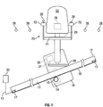
- a typical stairlift comprises a carriage 10 mounted on a rail 11 for movement along the rail between an upper end 12 and a lower end 13.
- the carriage includes a motor/gearbox unit 14 having a pinion 15 on the output thereof.
- the pinion engages a rack 16 extending along the underside of the rail.
- Mounted at each end of the rail 11 are limit switches 17. When engaged by the carriage as it reaches an end of the rail, the switches 17 cut power to the motor/gearbox 14.
- a chair 20 is mounted on the carriage 10 to accommodate a stairlift user.
- the chair 20 includes a chair base 21, a chair back 22, two spaced armrests 23 and a footrest 24.
- a hand control 25 is mounted on one of the armrests to allow the user to control movement of the carriage up and down the rail.
- ECU electronice control unit
- a monitoring system is applied to the stairlift to report information based on the position of the carriage 10 on the rail 11 and/or the activity of the carriage 10. For example, the system can generate an alert every time the carriage changes position and comes to rest. Alternatively, or in addition, the system can generate an alert reporting the position of the carriage at regular time intervals or at one or more prescribed times. Alternatively or in addition, the system might report the number of carriage movements in a prescribed time or the fact that there have been no movements for a prescribed time period.
- the system may report information relating to the ambient surroundings of the stairlift and/or the health of user.
- the system might be configured to generate data in a form so as to report a number of ambient conditions such as temperature, light level, carbon monoxide level, methane level, smoke presence, movement and/or a number of user parameters such as weight, temperature, heart rate, respiratory rate and/or galvanic response.
- the position of the carriage on the rail can be determined in any known manner including by the use of switches mounted on the rail 11 that are triggered when engaged by the carriage 10. Switches 17 could be used to determine the presence of the carriage at either end of the rail. Other position sensing technologies could include (but not be limited to) reed switches, mechanically actuated switches, ultrasound proximity sensors, optical-based sensors and near field identification systems. Position could also be determined by monitoring the rotation of the pinion 15 in a manner described in our European Patent No. 0 738 232 .
- a clock 27 may be incorporated in or associated with the ECU 26 to measure the time elapsing between stairlift movements and/or to record the number of carriage movements occurring within a prescribed period.
- the system is preferably configured to generate an alert in the event that the carriage changes position on the rail and/or after a prescribed period of time, say every five minutes, whether or not the carriage has moved.
- Other variations are within the scope of the invention including generating alerts of the position of the rail at one or more prescribed times during the day, and generating an alert in the event that the number of carriage movements in a prescribed period are less than a prescribed number.
- the system may include sensors 28 of any known form to collect data on the ambient conditions and to generate data representative of those conditions.
- the chair 20 may include sensors 29 in the chair base, backrest and/or armrests to capture user physiological data and to generate signals representative of that data.
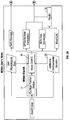
- Signals from the ECU 26, clock 27 and the position sensors are preferably collected in a micro controller 30 located in, or within the near vicinity of, the stairlift.
- the micro controller 30 may also collect data from the ambient surroundings sensors 28 and from the user physiological data sensors 29. Data from all sensors is configured by the micro controller 30 for delivery to central data service 31.
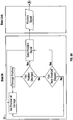
- FIG. 3 A possible operation of the microcontroller 30 is shown in Figure 3 .
- the microcontroller 30 monitors both carriage position and a time threshold. If there is a change of carriage position a position signal is generated and sent via a data link to a data service.
- the data service issues messages or alerts to authenticated devices as will be described in greater detail below. If a period of time has elapsed and that period of time exceeds a threshold defined in the microcontroller then, once again, a position signal is generated and sent via a data link to data service.
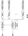
- the micro controller 30 may communicate with a remote central data service 31 in a number of alternative ways including by direct SMS or other mobile data link such as GSM, GPRS, 3G, 4G or via a wireless data or wired data link to a router 32 and thence via a broadband data link.
- the communication to the data service 31 could also be a combination of fixed-line using telephone lines or other cable-based networks, and wireless technologies.
- the micro-controller communicates wirelessly with a domestic broadband facility.
- the system might also employ a local receiver (not shown) to which data is communicated using Ethernet, BlueTooth, Zigbee, WiFi or other communication technology with the local receiver then passing on the data to the remote data service 31 using any suitable, compatible communication technology.
- a local receiver (not shown) to which data is communicated using Ethernet, BlueTooth, Zigbee, WiFi or other communication technology with the local receiver then passing on the data to the remote data service 31 using any suitable, compatible communication technology.
- the remote data service 31 is preferably a bespoke internet based application configured to receive data from the micro controller 30 in a number of suitable ways including GPRS/3G, 4G Wi-Fi and wired link via a Router.
- the data service 31 might also receive SMS messages converted as with other incoming data to HTTP format.
- the system according to the invention provides for the central data service 31 to relay information contained in the signals incoming from the ECU 26 or micro controller 30 to one or more subscribers via authenticated data receiving devices having installed thereon 'client' applications to enable interaction with the data service.
- authenticated data receiving devices include mobile telephones, tablet computers, personal computers, television sets and/or any other device or technology capable or imparting information to a human.
- the devices can be authenticated using Challenge-Handshake Authentication Protocol or other suitable authentication protocol.
- subscribers In order to exchange data with the data service, subscribers would have to be pre-authorized and log into the system using, for example, a user name and password.
- the precise configuration of the data service 31 is not essential to the invention. At its most simple the data service 31 would simply receive from the ECU 26 or micro controller 30, and pass on to subscribers, messages concerning stairlift activity. More sophisticated versions of the data service may be configured to discriminate between subscribers, passing certain types of information to some subscribers but not to others. The data service might also be configured to interpret more technical data into a form more easily understood by subscribers and even undertake analysis on data coming from the ECU or micro controller and decide whether or not (and in what form) such data should be passed on.
- the micro-controller may be configured to pass on a signal indicating carriage position every 5 minutes. If the data service does not receive a signal after a period of 5 minutes the data service may be configured to interpret this as a technical fault and to generate an appropriate alert to a specified subscriber. Assuming there is a constant flow of position information at 5 minute intervals, the data service may be configured not to pass this position information every 5 minutes but at longer periods, say every hour.
- the data service 30 would include a facility to communicate with media services such as (but not necessarily limited to) Twitter, Facebook and/or Google + to enable the distribution of data regarding stairlift activity via such media. SMS and e-mail are further options.
- a system according to the invention is configured to generate an alert or signal each time the carriage stops at the top or bottom of the rail. As the carriage 10 engages a switch 17 at the top or bottom of the rail a signal is sent to micro controller 30.
- the micro controller 30 includes a facility to connect to domestic wireless router and, through that, to an Internet data service.
- the incoming signals from the micro controller 30 are associated by the data service with the stairlift account and, once authorised, the signals are formatted appropriately and transmitted to native applications on phones and tablet computers or web applications accessible by browsers on computers, phones, tablets or other devices belonging to subscribers to the account.
- Followers or subscribers are limited to persons who elect to follow the stairlift and who are granted permission to do so by the account administrator. In this way subscribers, who may be relatives, friends or care-providers, can receive regular messages updating the position of the stairlift on its rail.
- the format of such updates may comprise, for example, '17.42 Went upstairs' or '18.12 Went downstairs'.
- the micro controller may also send a signal, say every 5 minutes, indicating stairlift position, which is interpreted by the data service and transmitted as a message to authenticated recipients in a form such as for example '9.05 Upstairs', at a longer time interval.
- telecommunications functionality is built into the ECU 26.
- the ECU is, in turn, configured in any known way to determine the position of the carriage 10 along the rail 11. This may be achieved by the use of switches along the rail feeding signals back to the ECU or may be achieved by electronically 'mapping' the rail using the technique described in our European Patent no. 0 738 232 .
- Telecommunications messages representing carriage position, time of movement, environmental conditions and/or user health are then sent using the facility in the ECU.
- the central data service 31 includes or comprises a bespoke application to receive and process messages from the stairlift and to generate and distribute ongoing messages to subscribers in the form of family, friends and/or care-providers.
- a bespoke application to receive and process messages from the stairlift and to generate and distribute ongoing messages to subscribers in the form of family, friends and/or care-providers.
- Associated with the data service 31 are 'client' applications for smartphone, tablets, computers and the like; as well as a web application viewable in a browser.
- Access by subscribers or followers would be by pre-authorized login.
- this example could still provide for alerts to be generated via media services such as Twitter, but other forms of message could be generated including, but not limited to, SMS and e-mail messages.
- the data service 31 may be configured to undertake some interpretation and/or discrimination, passing on some messages to some subscribers or followers, but not to others.
Landscapes
- Engineering & Computer Science (AREA)
- Transportation (AREA)
- Automation & Control Theory (AREA)
- Structural Engineering (AREA)
- Alarm Systems (AREA)
- Emergency Alarm Devices (AREA)
Description
- This invention relates to stairlifts and has been devised, in particular, to provide a monitoring method and apparatus associated with a stairlift.
- Stairlifts are, in many instances, installed in residential properties for use by people having a physical impairment, but who wish to remain living independently. However, inevitably a user's desire for independence is countered by concern on the part of family, friends and/or care-providers that the user is safe and well, and not in need of external assistance.
- Facilities for communication between remote parties are described in
WO03/098908 WO2010/141865 . -
WO03/098908 -
WO2010/141865 discloses methods and systems for lift monitoring. -
WO2007/045837 discloses a system for monitoring a fault in a mobility aid including a fault detector for detecting a fault. A signal generator is provided for generating a signal representative of the fault which is wirelessly transmitted to a remote location. The person controlling the mobility aid, if unable to move, request assistance or call for help, thus may be able to alert a third party to the problem. -
WO2006/109050 discloses a monitoring system for monitoring an apparatus for raising and lowering a person such as an adjustable furniture weight item or a hoist. The monitoring system comprises a memory for recording information relating to the history of the monitored apparatus. The memory may record periods when power supply to an actuator of the apparatus exceeds a predefined threshold, and the number of operations performed by the apparatus. When the number of operations reaches a predetermined amount the system can inhibit operation of the device. This means that the apparatus can prevent a user from using apparatus beyond a point that a maintenance service is recommended. - David Parkin: "Firm aims to increase jobs and turnover with intelligent home stairlift of future", Yorkshire Post, 2 November 2003 (2003-11-02), XP055246571, Retrieved from the Internet: URL:http://www.yorkshirepost.co.uk/news/firm-aims-to-increase-jobs-and-turnover-with-intelligent-home- stairlift-of-future-1 -2531627 [retrieved on 2016-02-01] discloses remote monitoring and diagnosis of faults in a stairlift to inform carers or contractors of immediate or future problems with stairlift equipment.
- It is an object of the invention to provide a method of, and/or apparatus for, addressing the desires and concerns expressed above; or which will at least offer a novel and useful choice.
- In one aspect the invention provides a method of monitoring a stairlift user as defined in
claim 1. - Preferably said method includes generating a signal for reception at a remote location in the event of a change in the position of said carriage on said rail.
- Preferably said method includes generating a signal for reception at a remote location as to the position of said carriage on said rail at regular time intervals.
- Preferably the method further comprises generating a signal for reception at a remote location representative of the number of carriage movements in a prescribed time or the fact there have been no movements for a prescribed time.
- Preferably said signals are transmitted to said remote location, at least in part, wirelessly.
- Said method may comprise transmitting data associated with said signal(s) to authenticated devices over the internet using Hypertext Transfer Protocol or other suitable data transfer protocols.
- Preferably a facility is provided to monitor ambient conditions in the proximity of the stairlift and/or to monitor one or more physiological parameters of a user while using said stairlift, said method comprising generating one or more signals representative of said ambient conditions and/or said physiological parameters and transmitting said signals to a remote location.
- In a second aspect the invention provides a system for monitoring a stairlift user as defined in claim 8.
- The various aspects of the invention will now described with reference to the accompanying drawings in which:
- Figure 1:
- shows a typical stairlift to which the invention may be applied;
- Figure 2:
- shows a schematic of the components of a system according to the invention; and
- Figure 3:
- shows a logic diagram of the system in operation.
- The present invention relates to a system for monitoring a stairlift user by monitoring the activity of a stairlift used by that user.
- Stairlifts are commonly installed in residences occupied by persons having a degree of infirmity. The stairlift enhances the mobility of the user and enables the user to address a number of the consequences of their infirmity. Once installed, the stairlift quickly becomes a part of the user's life with the stairlift's movements reflecting the rhythms of the user's activity.
- In a significant number of situations, a stairlift is installed to enable a user to continue living independently in their own home. Whilst this is of benefit to the stairlift user, family, friends and/or care-providers inevitably want assurance that the user is safe and able to function effectively when on their own.
- The present invention provides a method and system to not only endorse a stairlift user's desire for independence, but also to address the concerns of family, friends and/or care-providers.
- Referring to
Figure 1 a typical stairlift comprises acarriage 10 mounted on arail 11 for movement along the rail between anupper end 12 and alower end 13. To this end the carriage includes a motor/gearbox unit 14 having apinion 15 on the output thereof. The pinion engages arack 16 extending along the underside of the rail. Mounted at each end of therail 11 arelimit switches 17. When engaged by the carriage as it reaches an end of the rail, theswitches 17 cut power to the motor/gearbox 14. - In the conventional manner a
chair 20 is mounted on thecarriage 10 to accommodate a stairlift user. Thechair 20 includes achair base 21, a chair back 22, two spacedarmrests 23 and afootrest 24. Ahand control 25 is mounted on one of the armrests to allow the user to control movement of the carriage up and down the rail. - The various stairlift functions are typically placed under the control of an electronic control unit (ECU) 26 within the carriage.
- According to the present invention a monitoring system is applied to the stairlift to report information based on the position of the
carriage 10 on therail 11 and/or the activity of thecarriage 10. For example, the system can generate an alert every time the carriage changes position and comes to rest. Alternatively, or in addition, the system can generate an alert reporting the position of the carriage at regular time intervals or at one or more prescribed times. Alternatively or in addition, the system might report the number of carriage movements in a prescribed time or the fact that there have been no movements for a prescribed time period. - Alternatively, but preferably in addition, the system may report information relating to the ambient surroundings of the stairlift and/or the health of user. For example the system might be configured to generate data in a form so as to report a number of ambient conditions such as temperature, light level, carbon monoxide level, methane level, smoke presence, movement and/or a number of user parameters such as weight, temperature, heart rate, respiratory rate and/or galvanic response.
- The position of the carriage on the rail can be determined in any known manner including by the use of switches mounted on the
rail 11 that are triggered when engaged by thecarriage 10.Switches 17 could be used to determine the presence of the carriage at either end of the rail. Other position sensing technologies could include (but not be limited to) reed switches, mechanically actuated switches, ultrasound proximity sensors, optical-based sensors and near field identification systems. Position could also be determined by monitoring the rotation of thepinion 15 in a manner described in ourEuropean Patent No. 0 738 232 . - To determine stairlift activity a
clock 27 may be incorporated in or associated with theECU 26 to measure the time elapsing between stairlift movements and/or to record the number of carriage movements occurring within a prescribed period. However, and more simply, the system is preferably configured to generate an alert in the event that the carriage changes position on the rail and/or after a prescribed period of time, say every five minutes, whether or not the carriage has moved. Other variations are within the scope of the invention including generating alerts of the position of the rail at one or more prescribed times during the day, and generating an alert in the event that the number of carriage movements in a prescribed period are less than a prescribed number. - The system may include
sensors 28 of any known form to collect data on the ambient conditions and to generate data representative of those conditions. Similarly, thechair 20 may includesensors 29 in the chair base, backrest and/or armrests to capture user physiological data and to generate signals representative of that data. - Signals from the
ECU 26,clock 27 and the position sensors are preferably collected in amicro controller 30 located in, or within the near vicinity of, the stairlift. As can be seen fromFigure 2 , themicro controller 30 may also collect data from theambient surroundings sensors 28 and from the userphysiological data sensors 29. Data from all sensors is configured by themicro controller 30 for delivery to central data service 31. - A possible operation of the
microcontroller 30 is shown inFigure 3 . As can be seen themicrocontroller 30 monitors both carriage position and a time threshold. If there is a change of carriage position a position signal is generated and sent via a data link to a data service. The data service, in turn, issues messages or alerts to authenticated devices as will be described in greater detail below. If a period of time has elapsed and that period of time exceeds a threshold defined in the microcontroller then, once again, a position signal is generated and sent via a data link to data service. - The
micro controller 30 may communicate with a remote central data service 31 in a number of alternative ways including by direct SMS or other mobile data link such as GSM, GPRS, 3G, 4G or via a wireless data or wired data link to arouter 32 and thence via a broadband data link. The communication to the data service 31 could also be a combination of fixed-line using telephone lines or other cable-based networks, and wireless technologies. - In the preferred embodiment, the micro-controller communicates wirelessly with a domestic broadband facility.
- The system might also employ a local receiver (not shown) to which data is communicated using Ethernet, BlueTooth, Zigbee, WiFi or other communication technology with the local receiver then passing on the data to the remote data service 31 using any suitable, compatible communication technology.
- The remote data service 31 is preferably a bespoke internet based application configured to receive data from the
micro controller 30 in a number of suitable ways including GPRS/3G, 4G Wi-Fi and wired link via a Router. The data service 31 might also receive SMS messages converted as with other incoming data to HTTP format. - The system according to the invention provides for the central data service 31 to relay information contained in the signals incoming from the
ECU 26 ormicro controller 30 to one or more subscribers via authenticated data receiving devices having installed thereon 'client' applications to enable interaction with the data service. Examples of such devices include mobile telephones, tablet computers, personal computers, television sets and/or any other device or technology capable or imparting information to a human. The devices can be authenticated using Challenge-Handshake Authentication Protocol or other suitable authentication protocol. - In order to exchange data with the data service, subscribers would have to be pre-authorized and log into the system using, for example, a user name and password.
- The precise configuration of the data service 31 is not essential to the invention. At its most simple the data service 31 would simply receive from the
ECU 26 ormicro controller 30, and pass on to subscribers, messages concerning stairlift activity. More sophisticated versions of the data service may be configured to discriminate between subscribers, passing certain types of information to some subscribers but not to others. The data service might also be configured to interpret more technical data into a form more easily understood by subscribers and even undertake analysis on data coming from the ECU or micro controller and decide whether or not (and in what form) such data should be passed on. - By way of example, the micro-controller may be configured to pass on a signal indicating carriage position every 5 minutes. If the data service does not receive a signal after a period of 5 minutes the data service may be configured to interpret this as a technical fault and to generate an appropriate alert to a specified subscriber. Assuming there is a constant flow of position information at 5 minute intervals, the data service may be configured not to pass this position information every 5 minutes but at longer periods, say every hour.
- It is also envisaged that the
data service 30 would include a facility to communicate with media services such as (but not necessarily limited to) Twitter, Facebook and/or Google + to enable the distribution of data regarding stairlift activity via such media. SMS and e-mail are further options. - A system according to the invention is configured to generate an alert or signal each time the carriage stops at the top or bottom of the rail. As the
carriage 10 engages aswitch 17 at the top or bottom of the rail a signal is sent tomicro controller 30. Themicro controller 30 includes a facility to connect to domestic wireless router and, through that, to an Internet data service. - The incoming signals from the
micro controller 30 are associated by the data service with the stairlift account and, once authorised, the signals are formatted appropriately and transmitted to native applications on phones and tablet computers or web applications accessible by browsers on computers, phones, tablets or other devices belonging to subscribers to the account. - Followers or subscribers are limited to persons who elect to follow the stairlift and who are granted permission to do so by the account administrator. In this way subscribers, who may be relatives, friends or care-providers, can receive regular messages updating the position of the stairlift on its rail. The format of such updates may comprise, for example, '17.42 Went upstairs' or '18.12 Went downstairs'.
- The micro controller may also send a signal, say every 5 minutes, indicating stairlift position, which is interpreted by the data service and transmitted as a message to authenticated recipients in a form such as for example '9.05 Upstairs', at a longer time interval.
- In the stairlift shown in
Figure 1 , telecommunications functionality is built into theECU 26. The ECU is, in turn, configured in any known way to determine the position of thecarriage 10 along therail 11. This may be achieved by the use of switches along the rail feeding signals back to the ECU or may be achieved by electronically 'mapping' the rail using the technique described in ourEuropean Patent no. 0 738 232 . - Telecommunications messages representing carriage position, time of movement, environmental conditions and/or user health are then sent using the facility in the ECU.
- Messages are sent to a central data service 31 via the internet by any suitable communications technology/protocol. The central data service 31 includes or comprises a bespoke application to receive and process messages from the stairlift and to generate and distribute ongoing messages to subscribers in the form of family, friends and/or care-providers. Associated with the data service 31 are 'client' applications for smartphone, tablets, computers and the like; as well as a web application viewable in a browser.
- Access by subscribers or followers would be by pre-authorized login.
- In its simplest form this example could still provide for alerts to be generated via media services such as Twitter, but other forms of message could be generated including, but not limited to, SMS and e-mail messages.
- The data service 31 may be configured to undertake some interpretation and/or discrimination, passing on some messages to some subscribers or followers, but not to others.
- It will thus be appreciated that the invention described herein provides an effective means of monitoring the behaviour of a stairlift user and, thereby, enhances the independence of that use.
Claims (13)
- A method of monitoring a stairlift user, monitoring from a remote location the activity of a stairlift carriage (10) on a stairlift rail (11) when used by said user; characterized in that the method includes the following steps:i) monitoring the position of said carriage (10) on said rail (11);ii) monitoring each time the carriage (10) changes position on said rail (11) then comes to rest;iii) monitoring the position of said carriage (10) on said rail (11) at regular time intervals or at defined times;iv) monitoring the number of carriage (10) movements on said rail in a prescribed time or the fact that there have been no movements for a prescribed period.
- A method as claimed in claim 1 including generating a signal for reception at a remote location in the event of a change in the position of said carriage (10) on said rail (11).
- A method as claimed in claim 1 or claim 2 further comprising generating a signal for reception at a remote location as to the position of said carriage (10) on said rail (11) at regular time intervals or at defined times.
- A method as claimed in any of claims 1 to 3 further comprising generating a signal for reception at a remote location representative of the number of carriage (10) movements in a prescribed time or the fact there have been no movements for a prescribed time.
- A method as claimed in any one of claims 2 to 4 wherein said signal(s) are transmitted to said remote location, at least in part, wirelessly.
- A method as claimed in any one of claims 2 to 5 comprising distributing data representing said signal(s) to authenticated devices over the internet using Hypertext Transfer Protocol or other suitable data transfer protocols.
- A method as claimed in any one of the preceding claims wherein a facility (28, 29) is provided to monitor ambient conditions in the proximity of the stairlift and/or to monitor one of more physiological parameters of a user while using said stairlift, said method comprising generating one or more signals representative of said ambient conditions and/or said physiological parameters and transmitting said signals to a remote location.
- A system for monitoring a stairlift user, said system including a facility for monitoring the activity of a stairlift used by said user, said stairlift having a stairlift carriage (10) mounted on a stairlift rail (11), said system being characterized in that said monitoring facility is configured to monitor:i) the position of said carriage (10) on said rail (11);ii) each time the carriage changes position on said rail and then comes to rest;iii) the position of said carriage (10) on said rail (11) at regular time intervals or at defined times;iv) the number of carriage (10) movements on said rail (11) in a prescribed period or the fact that there have been no movements for a prescribed period;said system further including a transmit facility (30) for transmitting to a remote location one or more signals representative of said activity.
- A system as claimed in claim 8 including a facility (28, 29) to monitor ambient conditions in the vicinity of said stairlift and/or physiological parameters of said user whilst using said stairlift, said system being further operable to transmit to a remote location, at least one signal representative of said ambient conditions and/or said physiological parameters.
- A system as claimed in any one of claims 8 or claim 9 wherein said signals are transmitted to a remote data service using GSM, GPRS, 3G, 4G, WiFi and/or other functional wired and/or wireless communication facility.
- A system as claimed in claim 10 wherein said remote data service is operable to receive and interpret one or more of said signals identifying the position of said carriage (10) on said rail (11) and to pass on to identified recipients messages derived from said one or more signals.
- A system as claimed in claim 11 wherein said remote data service is configured to distribute data derived from said signals over the internet using Hypertext Transfer Protocol or other functioning data exchange protocol.
- A system as claimed in claim 11 or claim 12 using a media service to relay data to an authenticated receiver, and preferably wherein said media service is Twitter, Facebook and/or Google +.
Applications Claiming Priority (2)
| Application Number | Priority Date | Filing Date | Title |
|---|---|---|---|
| GBGB1216283.0A GB201216283D0 (en) | 2012-09-12 | 2012-09-12 | Improvements in or relating to stairlifts |
| PCT/GB2013/052381 WO2014041351A1 (en) | 2012-09-12 | 2013-09-12 | Improvements in or relating to stairlifts |
Publications (2)
| Publication Number | Publication Date |
|---|---|
| EP2895415A1 EP2895415A1 (en) | 2015-07-22 |
| EP2895415B1 true EP2895415B1 (en) | 2021-08-04 |
Family
ID=47137337
Family Applications (1)
| Application Number | Title | Priority Date | Filing Date |
|---|---|---|---|
| EP13766127.8A Active EP2895415B1 (en) | 2012-09-12 | 2013-09-12 | Improvements in or relating to stairlifts |
Country Status (3)
| Country | Link |
|---|---|
| EP (1) | EP2895415B1 (en) |
| GB (2) | GB201216283D0 (en) |
| WO (1) | WO2014041351A1 (en) |
Families Citing this family (8)
| Publication number | Priority date | Publication date | Assignee | Title |
|---|---|---|---|---|
| GB201301871D0 (en) * | 2013-02-01 | 2013-03-20 | Acorn Mobility Services Ltd | Monitored stairlift |
| GB2550323A (en) * | 2016-04-13 | 2017-11-22 | Christopher Rees John | Patient movement apparatus with alarm |
| GB2597871B (en) * | 2017-01-17 | 2022-07-20 | Stannah Stairlifts Ltd | Improvements in or relating to stairlifts |
| IT201700053752A1 (en) * | 2017-05-18 | 2018-11-18 | Marco Barsotti | stairlift remote control |
| EP3406555B1 (en) * | 2017-05-23 | 2019-11-27 | thyssenkrupp Stairlifts B.V. | Platform lift |
| GB201712745D0 (en) | 2017-08-09 | 2017-09-20 | Stannah Stairlifts Ltd | Improvements in or relating to stairlifts |
| GB201814618D0 (en) * | 2018-09-07 | 2018-10-24 | Stannah Stairlifts Ltd | Improvements in or relating to stairlifts |
| CA3180918A1 (en) * | 2020-06-23 | 2021-12-30 | Dave TROTSENBURG | Method for raising an alert in connection with the use of a platform lift |
Citations (8)
| Publication number | Priority date | Publication date | Assignee | Title |
|---|---|---|---|---|
| NL9300085A (en) | 1993-01-15 | 1994-08-01 | Brinkman Liftenfabriek Bv | Method and device for guiding the movement of a vehicle, in particular a stairlift |
| GB2312057A (en) | 1996-04-08 | 1997-10-15 | Hitachi Ltd | Supervisory system for passenger conveyer |
| WO2003098908A1 (en) | 2002-05-21 | 2003-11-27 | Philip Bernard Wesby | System and method for remote asset management |
| GB2391539B (en) | 2002-08-10 | 2005-09-21 | Stannah Stairlifts Ltd | Improvement in or relating to stairlifts |
| DE19651727B4 (en) | 1996-12-12 | 2006-02-09 | Siemens Ag | Disabled Elevator |
| WO2006109050A2 (en) * | 2005-04-09 | 2006-10-19 | Joerns Healthcare Limited | Monitoring system |
| WO2007045837A1 (en) | 2005-10-21 | 2007-04-26 | Minivator Limited | Wireless fault monitoring system |
| WO2010141865A1 (en) | 2009-06-05 | 2010-12-09 | Intellicare Network, Llc | Methods and systems for monitoring lift usage |
Family Cites Families (5)
| Publication number | Priority date | Publication date | Assignee | Title |
|---|---|---|---|---|
| US6093146A (en) * | 1998-06-05 | 2000-07-25 | Matsushita Electric Works, Ltd. | Physiological monitoring |
| GB2357389B (en) * | 1999-12-10 | 2002-02-13 | Telemetrics Ltd | Telemetry systems |
| ES2362414T3 (en) * | 2000-05-19 | 2011-07-05 | Welch Allyn Protocol Inc | PATIENT MONITORING SYSTEM. |
| US7319386B2 (en) * | 2004-08-02 | 2008-01-15 | Hill-Rom Services, Inc. | Configurable system for alerting caregivers |
| DE102005050424B4 (en) | 2005-10-19 | 2009-10-22 | W.C. Heraeus Gmbh | Sputtering target made of multi-component alloys |
-
2012
- 2012-09-12 GB GBGB1216283.0A patent/GB201216283D0/en not_active Ceased
-
2013
- 2013-09-12 EP EP13766127.8A patent/EP2895415B1/en active Active
- 2013-09-12 WO PCT/GB2013/052381 patent/WO2014041351A1/en not_active Ceased
- 2013-09-12 GB GB1316224.3A patent/GB2507178A/en not_active Withdrawn
Patent Citations (8)
| Publication number | Priority date | Publication date | Assignee | Title |
|---|---|---|---|---|
| NL9300085A (en) | 1993-01-15 | 1994-08-01 | Brinkman Liftenfabriek Bv | Method and device for guiding the movement of a vehicle, in particular a stairlift |
| GB2312057A (en) | 1996-04-08 | 1997-10-15 | Hitachi Ltd | Supervisory system for passenger conveyer |
| DE19651727B4 (en) | 1996-12-12 | 2006-02-09 | Siemens Ag | Disabled Elevator |
| WO2003098908A1 (en) | 2002-05-21 | 2003-11-27 | Philip Bernard Wesby | System and method for remote asset management |
| GB2391539B (en) | 2002-08-10 | 2005-09-21 | Stannah Stairlifts Ltd | Improvement in or relating to stairlifts |
| WO2006109050A2 (en) * | 2005-04-09 | 2006-10-19 | Joerns Healthcare Limited | Monitoring system |
| WO2007045837A1 (en) | 2005-10-21 | 2007-04-26 | Minivator Limited | Wireless fault monitoring system |
| WO2010141865A1 (en) | 2009-06-05 | 2010-12-09 | Intellicare Network, Llc | Methods and systems for monitoring lift usage |
Non-Patent Citations (1)
| Title |
|---|
| DAVID PARKIN: "Firm aims to increase jobs and turnover with intelligent home stairlift of future", YORKSHIRE POST, 2 November 2003 (2003-11-02), XP055246571, Retrieved from the Internet <URL:http://www.yorkshirepost.co.uk/news/firm-aims-to-increase-jobs-and-turnover-with-intelligent-home-stairlift-of-future-1-2531627> [retrieved on 20160201] * |
Also Published As
| Publication number | Publication date |
|---|---|
| EP2895415A1 (en) | 2015-07-22 |
| GB201216283D0 (en) | 2012-10-24 |
| WO2014041351A1 (en) | 2014-03-20 |
| GB201316224D0 (en) | 2013-10-30 |
| GB2507178A (en) | 2014-04-23 |
Similar Documents
| Publication | Publication Date | Title |
|---|---|---|
| EP2895415B1 (en) | Improvements in or relating to stairlifts | |
| Williams et al. | A smart fall and activity monitor for telecare applications | |
| JP6509598B2 (en) | Oversight support system | |
| US20150022342A1 (en) | Systems and methods for automated personal emergency responses | |
| KR102131969B1 (en) | System and method for protecting the lonely death using services based Information and Communication Technology | |
| US20100295684A1 (en) | Personal health management device | |
| US20140232556A1 (en) | Wireless, multi-point patient monitoring system | |
| US20150194032A1 (en) | Wellbeing monitor | |
| JP5912952B2 (en) | Dementia early stage identification system | |
| JP2004326623A (en) | Internet remote monitoring method for safety, and program | |
| GB2459174A (en) | Remote monitoring and evaluation of health or cognitive ability of a person | |
| CA2781251A1 (en) | Method of personal safety monitoring and mobile application for same | |
| JP2011177500A (en) | Body temperature management system | |
| GB2578203A (en) | Improvements in or relating to stairlifts | |
| JP5909832B1 (en) | Centralized water meter reading device with safety monitoring function | |
| JP2007282701A (en) | Biological information collection system | |
| JP2008097262A (en) | Monitoring system | |
| KR20150090941A (en) | Ubiquitous remote health monitoring system and method | |
| Maynard et al. | Smart home system for patients with mild cognitive impairment | |
| JP2000298784A (en) | System for confirming safety of people requiring nursing care | |
| EP3401888A1 (en) | Method and system for validating an alarm situation | |
| JP3153831U (en) | Information distribution system for watching followers living alone | |
| JP2002109667A (en) | Life monitoring system | |
| CN113204195A (en) | Intelligent home system suitable for old people | |
| CN101557549A (en) | Multiple physiological safety notification system |
Legal Events
| Date | Code | Title | Description |
|---|---|---|---|
| PUAI | Public reference made under article 153(3) epc to a published international application that has entered the european phase |
Free format text: ORIGINAL CODE: 0009012 |
|
| 17P | Request for examination filed |
Effective date: 20150224 |
|
| AK | Designated contracting states |
Kind code of ref document: A1 Designated state(s): AL AT BE BG CH CY CZ DE DK EE ES FI FR GB GR HR HU IE IS IT LI LT LU LV MC MK MT NL NO PL PT RO RS SE SI SK SM TR |
|
| AX | Request for extension of the european patent |
Extension state: BA ME |
|
| TPAC | Observations filed by third parties |
Free format text: ORIGINAL CODE: EPIDOSNTIPA |
|
| DAX | Request for extension of the european patent (deleted) | ||
| 17Q | First examination report despatched |
Effective date: 20160610 |
|
| STAA | Information on the status of an ep patent application or granted ep patent |
Free format text: STATUS: EXAMINATION IS IN PROGRESS |
|
| TPAC | Observations filed by third parties |
Free format text: ORIGINAL CODE: EPIDOSNTIPA |
|
| GRAP | Despatch of communication of intention to grant a patent |
Free format text: ORIGINAL CODE: EPIDOSNIGR1 |
|
| STAA | Information on the status of an ep patent application or granted ep patent |
Free format text: STATUS: GRANT OF PATENT IS INTENDED |
|
| INTG | Intention to grant announced |
Effective date: 20210420 |
|
| GRAS | Grant fee paid |
Free format text: ORIGINAL CODE: EPIDOSNIGR3 |
|
| GRAA | (expected) grant |
Free format text: ORIGINAL CODE: 0009210 |
|
| STAA | Information on the status of an ep patent application or granted ep patent |
Free format text: STATUS: THE PATENT HAS BEEN GRANTED |
|
| AK | Designated contracting states |
Kind code of ref document: B1 Designated state(s): AL AT BE BG CH CY CZ DE DK EE ES FI FR GB GR HR HU IE IS IT LI LT LU LV MC MK MT NL NO PL PT RO RS SE SI SK SM TR |
|
| REG | Reference to a national code |
Ref country code: GB Ref legal event code: FG4D |
|
| REG | Reference to a national code |
Ref country code: AT Ref legal event code: REF Ref document number: 1416802 Country of ref document: AT Kind code of ref document: T Effective date: 20210815 |
|
| REG | Reference to a national code |
Ref country code: CH Ref legal event code: EP |
|
| REG | Reference to a national code |
Ref country code: DE Ref legal event code: R096 Ref document number: 602013078646 Country of ref document: DE |
|
| REG | Reference to a national code |
Ref country code: IE Ref legal event code: FG4D |
|
| REG | Reference to a national code |
Ref country code: NL Ref legal event code: FP |
|
| REG | Reference to a national code |
Ref country code: LT Ref legal event code: MG9D |
|
| REG | Reference to a national code |
Ref country code: AT Ref legal event code: MK05 Ref document number: 1416802 Country of ref document: AT Kind code of ref document: T Effective date: 20210804 |
|
| PG25 | Lapsed in a contracting state [announced via postgrant information from national office to epo] |
Ref country code: SE Free format text: LAPSE BECAUSE OF FAILURE TO SUBMIT A TRANSLATION OF THE DESCRIPTION OR TO PAY THE FEE WITHIN THE PRESCRIBED TIME-LIMIT Effective date: 20210804 Ref country code: HR Free format text: LAPSE BECAUSE OF FAILURE TO SUBMIT A TRANSLATION OF THE DESCRIPTION OR TO PAY THE FEE WITHIN THE PRESCRIBED TIME-LIMIT Effective date: 20210804 Ref country code: AT Free format text: LAPSE BECAUSE OF FAILURE TO SUBMIT A TRANSLATION OF THE DESCRIPTION OR TO PAY THE FEE WITHIN THE PRESCRIBED TIME-LIMIT Effective date: 20210804 Ref country code: BG Free format text: LAPSE BECAUSE OF FAILURE TO SUBMIT A TRANSLATION OF THE DESCRIPTION OR TO PAY THE FEE WITHIN THE PRESCRIBED TIME-LIMIT Effective date: 20211104 Ref country code: LT Free format text: LAPSE BECAUSE OF FAILURE TO SUBMIT A TRANSLATION OF THE DESCRIPTION OR TO PAY THE FEE WITHIN THE PRESCRIBED TIME-LIMIT Effective date: 20210804 Ref country code: PT Free format text: LAPSE BECAUSE OF FAILURE TO SUBMIT A TRANSLATION OF THE DESCRIPTION OR TO PAY THE FEE WITHIN THE PRESCRIBED TIME-LIMIT Effective date: 20211206 Ref country code: RS Free format text: LAPSE BECAUSE OF FAILURE TO SUBMIT A TRANSLATION OF THE DESCRIPTION OR TO PAY THE FEE WITHIN THE PRESCRIBED TIME-LIMIT Effective date: 20210804 Ref country code: NO Free format text: LAPSE BECAUSE OF FAILURE TO SUBMIT A TRANSLATION OF THE DESCRIPTION OR TO PAY THE FEE WITHIN THE PRESCRIBED TIME-LIMIT Effective date: 20211104 Ref country code: FI Free format text: LAPSE BECAUSE OF FAILURE TO SUBMIT A TRANSLATION OF THE DESCRIPTION OR TO PAY THE FEE WITHIN THE PRESCRIBED TIME-LIMIT Effective date: 20210804 Ref country code: ES Free format text: LAPSE BECAUSE OF FAILURE TO SUBMIT A TRANSLATION OF THE DESCRIPTION OR TO PAY THE FEE WITHIN THE PRESCRIBED TIME-LIMIT Effective date: 20210804 |
|
| PG25 | Lapsed in a contracting state [announced via postgrant information from national office to epo] |
Ref country code: PL Free format text: LAPSE BECAUSE OF FAILURE TO SUBMIT A TRANSLATION OF THE DESCRIPTION OR TO PAY THE FEE WITHIN THE PRESCRIBED TIME-LIMIT Effective date: 20210804 Ref country code: LV Free format text: LAPSE BECAUSE OF FAILURE TO SUBMIT A TRANSLATION OF THE DESCRIPTION OR TO PAY THE FEE WITHIN THE PRESCRIBED TIME-LIMIT Effective date: 20210804 Ref country code: GR Free format text: LAPSE BECAUSE OF FAILURE TO SUBMIT A TRANSLATION OF THE DESCRIPTION OR TO PAY THE FEE WITHIN THE PRESCRIBED TIME-LIMIT Effective date: 20211105 |
|
| PG25 | Lapsed in a contracting state [announced via postgrant information from national office to epo] |
Ref country code: DK Free format text: LAPSE BECAUSE OF FAILURE TO SUBMIT A TRANSLATION OF THE DESCRIPTION OR TO PAY THE FEE WITHIN THE PRESCRIBED TIME-LIMIT Effective date: 20210804 |
|
| REG | Reference to a national code |
Ref country code: DE Ref legal event code: R026 Ref document number: 602013078646 Country of ref document: DE |
|
| PLBI | Opposition filed |
Free format text: ORIGINAL CODE: 0009260 |
|
| PLAB | Opposition data, opponent's data or that of the opponent's representative modified |
Free format text: ORIGINAL CODE: 0009299OPPO |
|
| PLBI | Opposition filed |
Free format text: ORIGINAL CODE: 0009260 |
|
| REG | Reference to a national code |
Ref country code: CH Ref legal event code: PL |
|
| REG | Reference to a national code |
Ref country code: BE Ref legal event code: MM Effective date: 20210930 |
|
| PLAX | Notice of opposition and request to file observation + time limit sent |
Free format text: ORIGINAL CODE: EPIDOSNOBS2 |
|
| PG25 | Lapsed in a contracting state [announced via postgrant information from national office to epo] |
Ref country code: SM Free format text: LAPSE BECAUSE OF FAILURE TO SUBMIT A TRANSLATION OF THE DESCRIPTION OR TO PAY THE FEE WITHIN THE PRESCRIBED TIME-LIMIT Effective date: 20210804 Ref country code: SK Free format text: LAPSE BECAUSE OF FAILURE TO SUBMIT A TRANSLATION OF THE DESCRIPTION OR TO PAY THE FEE WITHIN THE PRESCRIBED TIME-LIMIT Effective date: 20210804 Ref country code: RO Free format text: LAPSE BECAUSE OF FAILURE TO SUBMIT A TRANSLATION OF THE DESCRIPTION OR TO PAY THE FEE WITHIN THE PRESCRIBED TIME-LIMIT Effective date: 20210804 Ref country code: MC Free format text: LAPSE BECAUSE OF FAILURE TO SUBMIT A TRANSLATION OF THE DESCRIPTION OR TO PAY THE FEE WITHIN THE PRESCRIBED TIME-LIMIT Effective date: 20210804 Ref country code: EE Free format text: LAPSE BECAUSE OF FAILURE TO SUBMIT A TRANSLATION OF THE DESCRIPTION OR TO PAY THE FEE WITHIN THE PRESCRIBED TIME-LIMIT Effective date: 20210804 Ref country code: CZ Free format text: LAPSE BECAUSE OF FAILURE TO SUBMIT A TRANSLATION OF THE DESCRIPTION OR TO PAY THE FEE WITHIN THE PRESCRIBED TIME-LIMIT Effective date: 20210804 Ref country code: AL Free format text: LAPSE BECAUSE OF FAILURE TO SUBMIT A TRANSLATION OF THE DESCRIPTION OR TO PAY THE FEE WITHIN THE PRESCRIBED TIME-LIMIT Effective date: 20210804 |
|
| 26 | Opposition filed |
Opponent name: GRUND IPG PATENTANWAELTE UND SOLICITOR PARTG MBB Effective date: 20220429 |
|
| 26 | Opposition filed |
Opponent name: OTOLIFT TRAPLIFTEN B.V. Effective date: 20220503 |
|
| R26 | Opposition filed (corrected) |
Opponent name: GRUND IPG PATENTANWAELTE UND SOLICITOR PARTG MBB Effective date: 20220429 |
|
| PLAB | Opposition data, opponent's data or that of the opponent's representative modified |
Free format text: ORIGINAL CODE: 0009299OPPO |
|
| R26 | Opposition filed (corrected) |
Opponent name: GRUND IPG PATENTANWAELTE UND SOLICITOR PARTG MBB Effective date: 20220429 |
|
| PG25 | Lapsed in a contracting state [announced via postgrant information from national office to epo] |
Ref country code: LU Free format text: LAPSE BECAUSE OF NON-PAYMENT OF DUE FEES Effective date: 20210912 Ref country code: IE Free format text: LAPSE BECAUSE OF NON-PAYMENT OF DUE FEES Effective date: 20210912 Ref country code: BE Free format text: LAPSE BECAUSE OF NON-PAYMENT OF DUE FEES Effective date: 20210930 |
|
| PG25 | Lapsed in a contracting state [announced via postgrant information from national office to epo] |
Ref country code: SI Free format text: LAPSE BECAUSE OF FAILURE TO SUBMIT A TRANSLATION OF THE DESCRIPTION OR TO PAY THE FEE WITHIN THE PRESCRIBED TIME-LIMIT Effective date: 20210804 Ref country code: LI Free format text: LAPSE BECAUSE OF NON-PAYMENT OF DUE FEES Effective date: 20210930 Ref country code: CH Free format text: LAPSE BECAUSE OF NON-PAYMENT OF DUE FEES Effective date: 20210930 |
|
| PLBB | Reply of patent proprietor to notice(s) of opposition received |
Free format text: ORIGINAL CODE: EPIDOSNOBS3 |
|
| PG25 | Lapsed in a contracting state [announced via postgrant information from national office to epo] |
Ref country code: HU Free format text: LAPSE BECAUSE OF FAILURE TO SUBMIT A TRANSLATION OF THE DESCRIPTION OR TO PAY THE FEE WITHIN THE PRESCRIBED TIME-LIMIT; INVALID AB INITIO Effective date: 20130912 |
|
| P01 | Opt-out of the competence of the unified patent court (upc) registered |
Effective date: 20230523 |
|
| PG25 | Lapsed in a contracting state [announced via postgrant information from national office to epo] |
Ref country code: CY Free format text: LAPSE BECAUSE OF FAILURE TO SUBMIT A TRANSLATION OF THE DESCRIPTION OR TO PAY THE FEE WITHIN THE PRESCRIBED TIME-LIMIT Effective date: 20210804 |
|
| PG25 | Lapsed in a contracting state [announced via postgrant information from national office to epo] |
Ref country code: MK Free format text: LAPSE BECAUSE OF FAILURE TO SUBMIT A TRANSLATION OF THE DESCRIPTION OR TO PAY THE FEE WITHIN THE PRESCRIBED TIME-LIMIT Effective date: 20210804 |
|
| PG25 | Lapsed in a contracting state [announced via postgrant information from national office to epo] |
Ref country code: MT Free format text: LAPSE BECAUSE OF FAILURE TO SUBMIT A TRANSLATION OF THE DESCRIPTION OR TO PAY THE FEE WITHIN THE PRESCRIBED TIME-LIMIT Effective date: 20210804 |
|
| PGFP | Annual fee paid to national office [announced via postgrant information from national office to epo] |
Ref country code: NL Payment date: 20250924 Year of fee payment: 13 Ref country code: IT Payment date: 20250923 Year of fee payment: 13 |
|
| PGFP | Annual fee paid to national office [announced via postgrant information from national office to epo] |
Ref country code: GB Payment date: 20250929 Year of fee payment: 13 |
|
| PGFP | Annual fee paid to national office [announced via postgrant information from national office to epo] |
Ref country code: FR Payment date: 20250929 Year of fee payment: 13 |
|
| PG25 | Lapsed in a contracting state [announced via postgrant information from national office to epo] |
Ref country code: TR Free format text: LAPSE BECAUSE OF FAILURE TO SUBMIT A TRANSLATION OF THE DESCRIPTION OR TO PAY THE FEE WITHIN THE PRESCRIBED TIME-LIMIT Effective date: 20210804 |
|
| PGFP | Annual fee paid to national office [announced via postgrant information from national office to epo] |
Ref country code: DE Payment date: 20250929 Year of fee payment: 13 |
|
| APAH | Appeal reference modified |
Free format text: ORIGINAL CODE: EPIDOSCREFNO |
|
| APAW | Appeal reference deleted |
Free format text: ORIGINAL CODE: EPIDOSDREFNO |
|
| APBP | Date of receipt of notice of appeal recorded |
Free format text: ORIGINAL CODE: EPIDOSNNOA2O |
|
| PLAB | Opposition data, opponent's data or that of the opponent's representative modified |
Free format text: ORIGINAL CODE: 0009299OPPO |
|
| REG | Reference to a national code |
Ref country code: CH Ref legal event code: L10 Free format text: ST27 STATUS EVENT CODE: U-0-0-L10-L00 (AS PROVIDED BY THE NATIONAL OFFICE) Effective date: 20260218 |
|
| APBQ | Date of receipt of statement of grounds of appeal recorded |
Free format text: ORIGINAL CODE: EPIDOSNNOA3O |
|
| R26 | Opposition filed (corrected) |
Opponent name: GRUND IPG PATENTANWAELTE UND SOLICITOR PARTG MBB Effective date: 20220429 |
|
| APAH | Appeal reference modified |
Free format text: ORIGINAL CODE: EPIDOSCREFNO |