EP2894851A1 - Image processing device, image processing method, program, and computer-readable storage medium - Google Patents
Image processing device, image processing method, program, and computer-readable storage medium Download PDFInfo
- Publication number
- EP2894851A1 EP2894851A1 EP13842798.4A EP13842798A EP2894851A1 EP 2894851 A1 EP2894851 A1 EP 2894851A1 EP 13842798 A EP13842798 A EP 13842798A EP 2894851 A1 EP2894851 A1 EP 2894851A1
- Authority
- EP
- European Patent Office
- Prior art keywords
- image
- projection
- area
- projected
- size
- Prior art date
- Legal status (The legal status is an assumption and is not a legal conclusion. Google has not performed a legal analysis and makes no representation as to the accuracy of the status listed.)
- Granted
Links
Images







Classifications
-
- H—ELECTRICITY
- H04—ELECTRIC COMMUNICATION TECHNIQUE
- H04N—PICTORIAL COMMUNICATION, e.g. TELEVISION
- H04N9/00—Details of colour television systems
- H04N9/12—Picture reproducers
- H04N9/31—Projection devices for colour picture display, e.g. using electronic spatial light modulators [ESLM]
- H04N9/3141—Constructional details thereof
- H04N9/3173—Constructional details thereof wherein the projection device is specially adapted for enhanced portability
- H04N9/3176—Constructional details thereof wherein the projection device is specially adapted for enhanced portability wherein the projection device is incorporated in a camera
-
- G—PHYSICS
- G03—PHOTOGRAPHY; CINEMATOGRAPHY; ANALOGOUS TECHNIQUES USING WAVES OTHER THAN OPTICAL WAVES; ELECTROGRAPHY; HOLOGRAPHY
- G03B—APPARATUS OR ARRANGEMENTS FOR TAKING PHOTOGRAPHS OR FOR PROJECTING OR VIEWING THEM; APPARATUS OR ARRANGEMENTS EMPLOYING ANALOGOUS TECHNIQUES USING WAVES OTHER THAN OPTICAL WAVES; ACCESSORIES THEREFOR
- G03B17/00—Details of cameras or camera bodies; Accessories therefor
- G03B17/48—Details of cameras or camera bodies; Accessories therefor adapted for combination with other photographic or optical apparatus
- G03B17/54—Details of cameras or camera bodies; Accessories therefor adapted for combination with other photographic or optical apparatus with projector
-
- G—PHYSICS
- G06—COMPUTING OR CALCULATING; COUNTING
- G06F—ELECTRIC DIGITAL DATA PROCESSING
- G06F3/00—Input arrangements for transferring data to be processed into a form capable of being handled by the computer; Output arrangements for transferring data from processing unit to output unit, e.g. interface arrangements
- G06F3/14—Digital output to display device ; Cooperation and interconnection of the display device with other functional units
- G06F3/1415—Digital output to display device ; Cooperation and interconnection of the display device with other functional units with means for detecting differences between the image stored in the host and the images displayed on the displays
-
- G—PHYSICS
- G06—COMPUTING OR CALCULATING; COUNTING
- G06Q—INFORMATION AND COMMUNICATION TECHNOLOGY [ICT] SPECIALLY ADAPTED FOR ADMINISTRATIVE, COMMERCIAL, FINANCIAL, MANAGERIAL OR SUPERVISORY PURPOSES; SYSTEMS OR METHODS SPECIALLY ADAPTED FOR ADMINISTRATIVE, COMMERCIAL, FINANCIAL, MANAGERIAL OR SUPERVISORY PURPOSES, NOT OTHERWISE PROVIDED FOR
- G06Q30/00—Commerce
- G06Q30/06—Buying, selling or leasing transactions
- G06Q30/0601—Electronic shopping [e-shopping]
- G06Q30/0641—Electronic shopping [e-shopping] utilising user interfaces specially adapted for shopping
- G06Q30/0643—Electronic shopping [e-shopping] utilising user interfaces specially adapted for shopping graphically representing goods, e.g. 3D product representation
-
- G—PHYSICS
- G06—COMPUTING OR CALCULATING; COUNTING
- G06T—IMAGE DATA PROCESSING OR GENERATION, IN GENERAL
- G06T11/00—Two-dimensional [2D] image generation
- G06T11/10—Texturing; Colouring; Generation of textures or colours
-
- G—PHYSICS
- G06—COMPUTING OR CALCULATING; COUNTING
- G06T—IMAGE DATA PROCESSING OR GENERATION, IN GENERAL
- G06T11/00—Two-dimensional [2D] image generation
- G06T11/40—Filling planar surfaces by adding surface attributes, e.g. adding colours or textures
-
- G—PHYSICS
- G06—COMPUTING OR CALCULATING; COUNTING
- G06T—IMAGE DATA PROCESSING OR GENERATION, IN GENERAL
- G06T11/00—Two-dimensional [2D] image generation
- G06T11/60—Creating or editing images; Combining images with text
-
- G—PHYSICS
- G06—COMPUTING OR CALCULATING; COUNTING
- G06T—IMAGE DATA PROCESSING OR GENERATION, IN GENERAL
- G06T7/00—Image analysis
- G06T7/10—Segmentation; Edge detection
- G06T7/11—Region-based segmentation
-
- H—ELECTRICITY
- H04—ELECTRIC COMMUNICATION TECHNIQUE
- H04N—PICTORIAL COMMUNICATION, e.g. TELEVISION
- H04N5/00—Details of television systems
- H04N5/74—Projection arrangements for image reproduction, e.g. using eidophor
- H04N5/7408—Direct viewing projectors, e.g. an image displayed on a video CRT or LCD display being projected on a screen
-
- H—ELECTRICITY
- H04—ELECTRIC COMMUNICATION TECHNIQUE
- H04N—PICTORIAL COMMUNICATION, e.g. TELEVISION
- H04N9/00—Details of colour television systems
- H04N9/12—Picture reproducers
- H04N9/31—Projection devices for colour picture display, e.g. using electronic spatial light modulators [ESLM]
- H04N9/3179—Video signal processing therefor
-
- H—ELECTRICITY
- H04—ELECTRIC COMMUNICATION TECHNIQUE
- H04N—PICTORIAL COMMUNICATION, e.g. TELEVISION
- H04N9/00—Details of colour television systems
- H04N9/12—Picture reproducers
- H04N9/31—Projection devices for colour picture display, e.g. using electronic spatial light modulators [ESLM]
- H04N9/3179—Video signal processing therefor
- H04N9/3188—Scale or resolution adjustment
-
- H—ELECTRICITY
- H04—ELECTRIC COMMUNICATION TECHNIQUE
- H04N—PICTORIAL COMMUNICATION, e.g. TELEVISION
- H04N9/00—Details of colour television systems
- H04N9/12—Picture reproducers
- H04N9/31—Projection devices for colour picture display, e.g. using electronic spatial light modulators [ESLM]
- H04N9/3191—Testing thereof
- H04N9/3194—Testing thereof including sensor feedback
-
- G—PHYSICS
- G06—COMPUTING OR CALCULATING; COUNTING
- G06T—IMAGE DATA PROCESSING OR GENERATION, IN GENERAL
- G06T2207/00—Indexing scheme for image analysis or image enhancement
- G06T2207/10—Image acquisition modality
- G06T2207/10028—Range image; Depth image; 3D point clouds
-
- G—PHYSICS
- G06—COMPUTING OR CALCULATING; COUNTING
- G06T—IMAGE DATA PROCESSING OR GENERATION, IN GENERAL
- G06T2207/00—Indexing scheme for image analysis or image enhancement
- G06T2207/30—Subject of image; Context of image processing
- G06T2207/30196—Human being; Person
-
- G—PHYSICS
- G06—COMPUTING OR CALCULATING; COUNTING
- G06T—IMAGE DATA PROCESSING OR GENERATION, IN GENERAL
- G06T2210/00—Indexing scheme for image generation or computer graphics
- G06T2210/16—Cloth
-
- G—PHYSICS
- G09—EDUCATION; CRYPTOGRAPHY; DISPLAY; ADVERTISING; SEALS
- G09G—ARRANGEMENTS OR CIRCUITS FOR CONTROL OF INDICATING DEVICES USING STATIC MEANS TO PRESENT VARIABLE INFORMATION
- G09G2340/00—Aspects of display data processing
- G09G2340/04—Changes in size, position or resolution of an image
Definitions
- the present invention relates to an image processing device, an image processing method, a program, and a computer-readable storage medium.
- Non-patent literature 1 Bridget, "Outdoor media becomes a shoe store", [online], June 3, 2012 (retrieved on September 16, 2012), Internet (URL:http://www.adverblog.com/2012/06/03/outdoor-media-becomes -a-shoe-store/ )
- a user may have difficulties in combining a first object with a second object in front of the user in order to check the coordination, such as balance of sizes of the objects. More specifically, in some cases a user may have difficulties in bringing the second object to the front of the user to combine it with the first object, even though the first object is in front of the user.
- Examples of the first object include an item that a user considers purchasing.
- the above cases include giving a present of clothing. In this case, checking coordination of clothing together with a person who receives the present has been difficult. Other example is a case of looking for children's clothing, and making children stay still and wear clothes have been difficult.
- One or more embodiments of the present invention have been conceived in view of the above, and an object thereof is to provide a technology for checking coordination of a first object in front of a user and a second object, even if it is difficult to combine the first object and the second object in front of the user.
- an image processing device includes projection image acquiring means for acquiring a projection image including an image of a first object that is projected on a projection surface, object identifying means for identifying an area, in an image projected by projecting means on the projection surface, blocked by a second object in front of the projection surface, and projection control means for controlling the projecting means to project the projection image in which a size of the image of the first obj ect projected on the projection surface is life-size, and a color of the area identified by the object identifying means is replaced by a predetermined color.
- An image processing method includes the steps of acquiring a projection image including an image of a first object that is projected on a projection surface, identifying an area, in an image projected by projecting means on the projection surface, blocked by a second object in front of the projection surface, and controlling the projecting means to project the projection image in which a size of the image of the first object projected on the projection surface is life-size, and a color of the identified area is replaced by a predetermined color.
- a program causes a computer to function as projection image acquiring means for acquiring a projection image including an image of a first object that is projected on a projection surface, obj ect identifying means for identifying an area, in an image projected by projecting means on the projection surface, blocked by a second object in front of the projection surface, and projection control means for controlling the projecting means to project the projection image in which a size of the image of the first object projected on the projection surface is life-size, and a color of the area identified by the object identifying means is replaced by a predetermined color.
- a computer-readable storage medium stores the program.
- coordination of actual first object and second object can be checked even if it is difficult to match the objects each other in front of a user.
- the object identifying means may identify the area blocked by the second object based on a depth image that indicates a distance from each pixel to imaging device.
- the object identifying means may periodically identify the area blocked by the second object, and, every time the object identifying means identifies the area blocked by the second object, the projection control means may control the projecting means to project the projection image in which the color of the area identified by the object identifying means is replaced by the predetermined color.
- the user can check the coordination of the first object and the second object in real time while moving the second object.
- the projection image acquiring means may acquire one of a plurality of projection images, each of which includes a human body, and the projection control means may adjust a position of the acquired projection image based on a position of the image of the first object included in the acquired projection image.
- a positional relationship between the first object and the second object can be maintained even though the projection image is switched to another image.
- the projection image acquiring means may acquire one of the plurality of projection images based on the area identified by the object identifying means.
- the projection control means may acquire, from a user, information indicating a change of size of the projected first object, and change a size of the projection image from life-size based on the information indicating the change of size.
- the coordination when a size of the first object is expected to be changed, the coordination can be checked in view of the change in size.
- the projection control means may adjust the position of the projection image in a case where the projection image in life-size is changed in size based on the position of the identified area.
- an amount of moving the second object can be reduced.
- the projection control means may control the projection means to further project a predetermined image on the identified area.
- the projection control means in a first mode, may control the projecting means to project the projection image in which the color of the area identified by the object identifying means is replaced by the predetermined color, and in a second mode, the projection control means may control the projecting means to project the acquired projection image on an area, in the identified area, that has been identified as not being blocked by the second object at a timing instructed by the user.
- FIG. 1 illustrates an example of an image processing system according to an embodiment of the present invention.
- the image processing system includes an image processing device 1, a camera 2, and a projector 3.
- the image processing device 1 is a computer that a user operates, such as a personal computer and a portable terminal.
- the image processing device 1 includes a processor 11, a storage unit 12, a communication unit 13, and an input/output unit 14.
- the processor 11 operates according to a program stored in the storage unit 12.
- the processor 11 controls the communication unit 13 and the input/output unit 14.
- the program may be provided through the Internet, for example, or stored in a computer-readable storage medium such as a DVD-ROM and provided.
- the storage unit 12 includes a memory device such as a RAM or a flash memory, and a hard disk drive.
- the storage unit 12 stores the program. Further, the storage unit 12 stores information and computational results input from each unit.
- the communication unit 13 implements functions to communicate with other devices, and includes, for example, an integrated circuit constituting a wired LAN or a wireless LAN, and an antenna.
- the communication unit 13 inputs information received from other devices into the processor 11 and the storage unit 12, and sends information to other devices based on the control of the processor 11.
- the input/output unit 14 is a circuit for exchanging data with display output devices and other input/output devices, and includes, for example, a graphic board for outputting images on the display output device, and a USB controller obtaining data from an input device such as a keyboard, a mouse, and a camera 2.
- the input/output unit 14 outputs image data to the display output device and obtains information from an operator (user) using the input device and data acquired by the camera 2, based on the control of the processor 11.
- One of the display output devices connected to the input/output unit 14 is the projector 3, and another device is a display such as a liquid crystal display device (not shown).
- the camera 2 is a device for acquiring a visible image and a depth image.
- the depth image consists of a plurality of pixels arranged in two dimensions, and the respective pixels have information (distance) indicating distances between the camera 2 and respective objects in the directions of the pixels.
- the pixels included in the depth image may respectively have three-dimensional coordinates of the objects in the directions of the pixels.
- the portion of the camera 2, which acquires the depth image determines distances based on reflections of infrared rays irradiated on the objects as, for example, KINECT (registered trademark).
- a laser range finder, a camera projection system, and a stereo camera may be used for acquiring distances.
- the projector 3 is a projecting device that includes a light, a lens, and an element for controlling magnitude of output light for each pixel.
- the projector 3 projects an image indicated by image data that is input from the input/output unit 14 on, for example, a projection surface in the direction of the lens.
- a size of the projected image is increased.
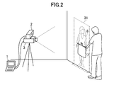
- FIG. 2 illustrates an example of arrangement of the camera 2, the projector 3, the projection surface, the object, and the projected image.
- the projection surface is a wall
- the object is a bottom wear 7
- the projected image is a body image 8.
- the user holds an object, such as the bottom wear 7, in front of the projection surface.
- the camera 2 then captures the projection surface and depth and visible images of the object in the projecting direction of the projector 3.
- the camera 2 has a unit that irradiates infrared light used for acquiring the depth image, and the longitudinal direction of the camera 2 is orthogonal to the photographing direction.
- the depth and visible images photographed by the camera 2 are sent to the image processing device 1, and the projector 3 projects the body image 8 on the wall.
- the body image 8 is projected on the projection surface in the size of the original or adjusted size of the original so that the body image 8 and the bottom wear 7 are easily compared in size.
- an object, such as the body image 8, projected on the projection surface is also described as a first object, and an object held in front of the projection surface is also described as a second object.
- the second object is not limited to the bottom wear 7, but may be a top wear or a curtain, for example. In a case where the second object is a curtain, a photograph of a room including a window may be used as a projected image.
- FIG. 3 is a block diagram illustrating functions implemented by the image processing device 1.
- the image processing device 1 functionally includes a projection image analyzing unit 51, a photographed data acquiring unit 52, a projection surface identifying unit 53, an object identifying unit 54, a projection image acquiring unit 55, and a projection control unit 56. These functions are implemented by the processor 11 by executing a program stored in the storage unit 12 and controlling the input/output unit 14 and the like.
- the projection image acquiring unit 55, object identifying unit 54, and projection control unit 56 respectively correspond to projection image acquiring means, object identifying means, project control means of the claims of the present invention.
- the projection image analyzing unit 51 is implemented mainly by the processor 11, the storage unit 12, and the communication unit 13.
- the projection image analyzing unit 51 obtains one or more projection images 31, which are candidates of images to be projected on the projection surface, and analyzes information for projecting an object included in the projection image 31, such as a body, in the size of the original and information for selecting one of the projection images 31.
- the projection images 31 include the body image 8 as an object image
- the former information is a pixel length in the projection image, which corresponds to a height
- the latter information is a manner of exposed skin parts.
- One of the projection images 31 is processed and projected by the projector 3.
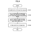
- FIG. 4 is a flow chart illustrating an example of processing of the projection image analyzing unit 51.
- the projection image analyzing unit 51 acquires image data of the projection images 31 (step S101).
- the projection images 31 are brought by the user and input into the image processing device 1.
- the projection image analyzing unit 51 may acquire image data stored in a nonvolatile memory, such as a flash memory, through the input/output unit 14 or the communication unit 13.
- the projection image analyzing unit 51 detects positions of the upper end, lower end, and head of the image of human body included in the projection image 31 (step S102).
- the projection image analyzing unit 51 detects a ratio of skin color in areas corresponding to the upper body and the lower body (step S103).
- the projection image analyzing unit 51 stores the detected information in the storage unit 12 (step S104).
- FIG. 5 illustrates an example of the projection image 31 and an example of a portion of an analysis target.
- a head area 43 of the human body, the upper end of the human body, which is the upper end of the head area 43 and indicated as a human body upper end line 41, and the lower end of the human body indicated as a lower end line 42 are directly detected from the image of the human body included in the projection image 31.
- the head area 43 is detected according to a method of so-called facial recognition.
- the projection image analyzing unit 51 may detect the upper end of the human body based on the result of the facial recognition, or detect an edge corresponding to the upper end of the head of the human body to acquire the upper end.
- the projection image analyzing unit 51 may also acquire the lower end of the human body by detecting the edge corresponding to the shape of the human body. Alternatively, the projection image analyzing unit 51 may acquire the positions of the upper end and the lower end input by the user manually.
- a skin detection area 44 corresponding to the upper body and a skin detection area 45 corresponding to the lower body shown in FIG. 5 are areas for obtaining the ratio of skin color.
- the position or shape of these areas may be determined based on information on the lower end positions of the head area 43 and the human body.
- the relationship between the lower end positions of the head area 43 and the human body, and the skin detection areas 44 and 45 may be statistically analyzed in advance and calculated based on the result of the analysis. Further, the upper end position of the human body may be used for calculating the skin detection areas 44 and 45.
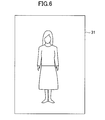
- FIG. 6 illustrates another example of the projection image 31.
- the image in FIG. 6 shows smaller parts of exposed skin of the human body compared to the image in FIG. 5 . Using this difference, an image to be projected on the projector is selected. Details thereof will be described later.
- FIG. 7 illustrates an example of information detected from the projection images 31.
- FIG. 7 shows an example of data when four projection images 31 are input.
- This detected data includes an image number which is information for identifying the projection images 31, a y-coordinate of the upper end and the lower end of the human body in the projection image 31, a coordinate indicating the center of the head, a ratio of skin color in the upper body in the skin detection area 44, and a ratio of skin color in the lower body in the skin detection area 45, as information corresponding to the upper end and the lower end of the human body, the position of the head, degree of exposed skin of the upper body, and degree of exposed skin of the lower body.
- the image number 1 shows lower ratio of skin color in the upper body and the lower body in the skin detection areas 44 and 45 than other projection images 31, and corresponds to the image shown in FIG. 6 , for example.
- the image number 3 shows higher ratio of skin color in the upper body and the lower body in the skin detection areas 44 and 45 than other projection images 31, and corresponds to an image of, for example, a swim-suited person.
- FIG. 8 is a flow chart showing an example of processing of a photographed data acquiring unit 52, a projection surface identifying unit 53, an object identifying unit 54, a projection image acquiring unit 55, and a projection control unit 56.
- the photographed data acquiring unit 52 is implemented mainly by the processor 11, the storage unit 12, and the input/output unit 14.
- the photographed data acquiring unit 52 acquires data of a depth image and a visible image of the projection surface and an object held in front of the projection surface which are photographed by the camera 2 (step S201).
- the projection surface identifying unit 53 is implemented mainly by the processor 11 and the storage unit 12.
- the projection surface identifying unit 53 identifies arrangement of the projection surface based on the depth image acquired by the photographed data acquiring unit 52 (step S202).
- Methods for detecting the projection surface may include extracting three or more points at the corners of the depth image, and identifying the position and the tilt of the projection surface based on the three-dimensional positions of the points.
- the projection surface identifying unit 53 detects a line of an edge, which has a depth that changes abruptly, from the depth image in advance, and eliminates the area surrounded by the line so as to extract the points for identifying the position and the tilt of the projection surface.
- the processing of the projection surface identifying unit 53 may be omitted. Instead of the processing, for example, the user may manually measure a distance to the projection surface in advance, and cause the storage unit 12 to store the distance.
- the object identifying unit 54 is implemented mainly by the processor 11 and the storage unit 12.
- the object identifying unit 54 identifies an object (second object) in front of the projection surface based on the depth image (step S203). More precisely, the object identifying unit 54 identifies an area 33, which is blocked by the second object, in the image that the projector 3 projects on the projection surface. Specifically, for example, the object identifying unit 54 detects a line of an edge where the distance from the camera 2 is changed abruptly in the depth image, and identifies an area surrounded by the line of the edge as the area 33 blocked by the second object.
- the object identifying unit 54 may identify, in the depth image, an area that is in front of the projection surface identified by the projection surface identifying unit 53 and away from the projection surface by a predetermined distance or more, as the area 33 blocked by the second object.
- the object identifying unit 54 may correct misalignment of the area due to the difference between spatial positions of the camera 2 and the projector 3 with use of correction information stored in advance.
- the correction information is, for example, information of misalignment in the XY direction between the image projected by the projector 3 and the image photographed by the camera 2.
- the object identifying unit 54 calculates the area 33 blocked by the second object based on the relationship between the spatial positions of the second object toward the camera 2 and the projector 3 toward the camera 2.
- the correction information indicating the spatial position of the second object toward the camera 2 can be calculated based on the image photographed by the camera 2.
- the object identifying unit 54 can identify the area 33 blocked by the second object before or after the projector 3 projects the projection image 31.
- the area 33 blocked by the second object may be an area, in the projection image 31, that is blocked by the second object when the projection image 31 is projected.
- FIG. 9A illustrates an example of a shape of an object in front of the projection surface.
- FIG. 9B is a diagram of an example of the area 33 indicating an object in front of the projection surface identified by the depth image.
- the depth image of the bottom wear 7 as shown in FIG. 9A shows that a distance from the camera 2 to a portion outside the edge of the bottom wear 7 is sharply increased compared to a distance from the camera 2 to a portion inside the edge of the bottom wear 7, and the difference of the distances is more than a predetermined value.
- the object identifying unit 54 may separate the bottom wear 7 from the projection surface in the rear of the bottom wear 7 by regarding an area consisting of pixels of images of the depth image, where each of the pixels is away from the camera 2 in a distance shorter than the threshold value, as the area 33 of the second object.
- the object identifying unit 54 may identify the area 33 blocked by the second object using the visible image. For example, the object identifying unit 54 may periodically generate a state in which the projection image 31 is not projected, and detect an edge of the second object in the visible image acquired in that state, thereby identifying the area 33 blocked by the second object.
- the projection image acquiring unit 55 is implemented mainly by the processor 11 and the storage unit 12.
- the projection image acquiring unit 55 selects one of the projection images 31 that are input by the user and analyzed by the projection image analyzing unit 51.
- the projection image analyzing unit 51 acquires information on sizes of the human body (step S204), and selects one of the projection images 31 based on whether or not the second object hides a detection area that is determined according to the first object included in the projection image 31 (step S205).
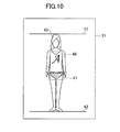
- FIG. 10 illustrates an example of relationship between the image of the human body and the detection areas 46 and 47.
- the detection area 46 is an area corresponding to the upper human body excluding arms and hands
- the detection area 47 is an area corresponding to the lower human body around hips.
- the projection image acquiring unit 55 selects an image having a smaller degree of exposed skin (ratio of skin color) in the skin detection area 44 corresponding to the upper body than a threshold value, as a candidate of the projection image 31. In this way, it is possible to prevent carelessly projecting an image having high degree of exposed skin of the upper body.
- the projection image acquiring unit 55 selects an image having a higher degree of exposed skin (ratio of skin color) in the skin detection area 44 corresponding to the upper body than a threshold value, as a candidate of the projection image 31. In this way, it is possible to prevent the top wear in the projection image 31 held in front of the upper body from being protruded from the second object (top wear).
- the projection image acquiring unit 55 acquires, among from the candidates, an image having a smaller degree of exposed skin in the skin detection area 45 corresponding to the lower body than the threshold value as the projection image 31. In this way, it is possible to prevent carelessly projecting an image having high degree of exposed skin in the lower body.
- the projection image acquiring unit 55 acquires an image having higher degree of exposed skin in the skin detection area 45 corresponding to the lower body than the threshold value as the projection image 31. In this way, it is possible to prevent the bottom wear in the projection image 31 held in front of the lower body from being protruded from the second object (bottom wear).
- the projection image 31 can be selected without using the ratio of skin color.
- the user may specify whether the exposure of the upper body and the lower body is high or not for each image in advance, and select an image based on such information.
- the information on sizes acquired in step S204 includes, for example, a height input by the user.
- information on ages of children may also be acquired as information on size.
- the projection image acquiring unit 55 may estimate a height of a child in six months based on the child's age, height, and known growth curve, and use the estimated height in the processing described below. In this way, when looking for clothing of a child, a user can easily check the coordination while considering growth of the child's height.
- the projection image acquiring unit 55 calculates positions and sizes of the detection areas 46 and 47 based on such size information, the position of the head area 43 and the position of the lower end human body, which are acquired from any of the projection images 31, and the projection surface.
- the projection image acquiring unit 55 may statistically analyze a relationship among the position of the head area 43, the position of the lower end human body and the positions of the detection areas 46 and 47 in advance, and calculate the positions and the sizes of the detection areas 46 and 47 based on the result of the analysis and the position of the projection surface.
- the projection image 31 may be selected manually. For example, a plurality of projection images 31 may be displayed and the user may select one of the projection images 31 to be projected by the projector 3.
- the projection control unit 56 implemented mainly by the processor 11, the storage unit 12, and the input/output unit 14.
- the projection control unit 56 controls the projector 3 to project the projection image 31.
- the projection control unit 56 controls the projector 3 so that, in the projection image 31, a size of an image of the first object projected on the projection surface is life-size and the area projected on the second object is covered.
- the projection control unit 56 adjusts a size of the projection image 31 (step S206). More specifically, the projection control unit 56 uses the information, which relates to the size of the second object and is acquired in the step S204, to enlarge and reduce the size of the projection image 31 so that the first object, such as the body image 8, included in the projection image 31 is displayed in or close to life-size on the projection surface.
- the projection control unit 56 may change the actual size of the first object to be projected in view of the child's age, for example, as described above.
- the rate of scaling is calculated using information on the size according to which the first object is projected, the size on the projection screen, and the projection surface (e.g., distance to projection surface).
- the projection surface is perpendicular to the projecting direction of the projector 3, it is determined how many pixels of the projector 3 correspond to a length of a line equivalent to the height of the human body in the distance of the projection surface. Then, a rate between the determined number of pixels and the number of pixels of the human body upper end line 41 and the lower end line 42 of the human body may be set as the rate of scaling.
- the projection control unit 56 adjusts the position of the projection image 31 (step S207).
- This processing is performed for projecting the projection image 31 at the same position even though the positions of the first object, such as a human body, are different depending on the projection images 31. More specifically, the position of the projection image 31 is adjusted such that the position of the head projected on the projection surface overlaps any of the projection images 31 selected.
- the projection control unit 56 may adjust the size and the position by converting image data of the projection image 31 with use of software or using hardware such as an image processing circuit mounted on a graphic board.
- the projection control unit 56 determines a display mode based on the user's operation (step S208). More specifically, the projection control unit 56 switches from a normal first mode to a second mode for checking an amount of correction of clothing, for example, when the user performs a predetermined action, such as fixing the position of the first object for a predetermined period of time or waving the first object slightly.
- a predetermined action such as fixing the position of the first object for a predetermined period of time or waving the first object slightly.
- the projection control unit 56 generates an image in which an area 33 projected on the second object in the projection image 31 is covered (step S209) .
- This processing varies depending on the display modes.
- the projection control unit 56 generates an image in which an area 33 projected on the second object is covered, by replacing the color of the area 33 that corresponds to the second object, such as FIG. 9B , identified by the object identifying unit 54, with a predetermined color.
- the projection control unit 56 In the second mode, the projection control unit 56 generates an image in which a projection image 31 is projected on an area that is a part of the area 33 on the second object and where the second object is not identified at a timing instructed by the user, and in which a part of the projection image 31 is not projected on other areas of the second object. More specifically, the processing for hiding the area is executed by, for example, painting over the area in white. Any color may be used for painting over the area unless it causes a problem of the color of the second object on which the color of the area is projected, however it may be preferable to use white or gray.
- the projection control unit 56 adds an additional image (step S210).
- the additional image is an image, such as a scale, that enables measuring a length of the bottom wear 7. More specifically, the projection control unit 56 adds, to the image processed in step S209, an image of a scale extending from the upper end to the lower end of the area 33 of the identified second object.
- the position of zero of the scale is, for example, the upper end (in a case of bottom wear 7) or the lower end of the area. This processing is executed in the first mode, and may not be executed or omitted in the second mode.
- FIG. 11 illustrates an example of an image that is projected on the projector 3 and processed in the first mode.
- a portion surrounded by the dashed line in FIG. 11 is a portion covered in the processing in step S209, and an image of a scale in the vertical direction is added as an additional image.
- the image of the scale is adjusted such that, when the scale is added to the bottom wear 7, the upper end portion of the bottom wear 7 is set as zero.
- FIG. 12 illustrates an example of the projected image and the second object in the first display mode.
- the processing by the image processing device 1 allows the user to feel a situation that the second object, which is the original, is held in front of the human body displayed on the projection image 31. In this way, it is possible to check an impression or a size when the original is combined with a person or an item that is difficult to be brought to a place where the original, such as a product, is placed. In addition, texture of an item, which is most important when looking for items, can be recognized. An image such as a scale is projected on the second object, and thus the user can easily find out amount of correction when it is tailor-made or a length needs to be adjusted.
- FIG. 13 illustrates an example of the projected image and the second object in the second display mode.
- the amount of correction can be easily recognized compared to checking it by rolling up the hem of the bottom wear 7.
- the user moves the position of the bottom wear 7 up and down and projects the human body at a portion that has moved upward from the original position, thereby further easily recognizing the amount of correction.
- FIG. 13 does not show a scale, although the projection control unit 56 may display a scale as shown in FIG. 11 .
- the projection control unit 56 may control the scale to extend from the upper end of an initial position area 34, which is covered by the bottom wear 7 at a timing the user instructs, to the lower end of the bottom wear 7 (area 33 corresponding to bottom wear 7) that has been moved (present time) . Further, the projection control unit 56 may display the scale starting from the lower end of the bottom wear 7 at the timing instructed by the user or the upper end of the moved bottom wear 7 so that the amount of movement can be recognized.
Landscapes
- Engineering & Computer Science (AREA)
- Physics & Mathematics (AREA)
- General Physics & Mathematics (AREA)
- Theoretical Computer Science (AREA)
- Multimedia (AREA)
- Signal Processing (AREA)
- Business, Economics & Management (AREA)
- Finance (AREA)
- Accounting & Taxation (AREA)
- Strategic Management (AREA)
- Computer Vision & Pattern Recognition (AREA)
- Development Economics (AREA)
- Economics (AREA)
- Marketing (AREA)
- General Business, Economics & Management (AREA)
- General Engineering & Computer Science (AREA)
- Human Computer Interaction (AREA)
- Projection Apparatus (AREA)
- Controls And Circuits For Display Device (AREA)
- Closed-Circuit Television Systems (AREA)
Abstract
Description
- The present invention relates to an image processing device, an image processing method, a program, and a computer-readable storage medium.
- When contemplating a purchase of clothing, people typically put items on their bodies to check their appearance, including impressions or sizes of the items of clothing (so-called coordination of clothes).
- There are technologies for compositing an image of clothes or shoes with an image of a human body photographed by a camera, and outputting the composite image on a display (see non-patent literature 1). Such technologies allow a user to view the composite image on the display so as to check coordination of clothes.
- Non-patent literature 1: Bridget, "Outdoor media becomes a shoe store", [online], June 3, 2012 (retrieved on September 16, 2012), Internet (URL:http://www.adverblog.com/2012/06/03/outdoor-media-becomes -a-shoe-store/)
- In some cases, a user may have difficulties in combining a first object with a second object in front of the user in order to check the coordination, such as balance of sizes of the objects. More specifically, in some cases a user may have difficulties in bringing the second object to the front of the user to combine it with the first object, even though the first object is in front of the user. Examples of the first object include an item that a user considers purchasing. The above cases include giving a present of clothing. In this case, checking coordination of clothing together with a person who receives the present has been difficult. Other example is a case of looking for children's clothing, and making children stay still and wear clothes have been difficult.
- One or more embodiments of the present invention have been conceived in view of the above, and an object thereof is to provide a technology for checking coordination of a first object in front of a user and a second object, even if it is difficult to combine the first object and the second object in front of the user.
- In order to solve the above described problems, an image processing device according to the present invention includes projection image acquiring means for acquiring a projection image including an image of a first object that is projected on a projection surface, object identifying means for identifying an area, in an image projected by projecting means on the projection surface, blocked by a second object in front of the projection surface, and projection control means for controlling the projecting means to project the projection image in which a size of the image of the first obj ect projected on the projection surface is life-size, and a color of the area identified by the object identifying means is replaced by a predetermined color.
- An image processing method according to the present invention includes the steps of acquiring a projection image including an image of a first object that is projected on a projection surface, identifying an area, in an image projected by projecting means on the projection surface, blocked by a second object in front of the projection surface, and controlling the projecting means to project the projection image in which a size of the image of the first object projected on the projection surface is life-size, and a color of the identified area is replaced by a predetermined color.
- A program according to the present invention causes a computer to function as projection image acquiring means for acquiring a projection image including an image of a first object that is projected on a projection surface, obj ect identifying means for identifying an area, in an image projected by projecting means on the projection surface, blocked by a second object in front of the projection surface, and projection control means for controlling the projecting means to project the projection image in which a size of the image of the first object projected on the projection surface is life-size, and a color of the area identified by the object identifying means is replaced by a predetermined color.
- A computer-readable storage medium according to the present invention stores the program.
- According to the present invention, coordination of actual first object and second object can be checked even if it is difficult to match the objects each other in front of a user.
- In an embodiment of the present invention, the object identifying means may identify the area blocked by the second object based on a depth image that indicates a distance from each pixel to imaging device.
- In an embodiment of the present invention, the object identifying means may periodically identify the area blocked by the second object, and, every time the object identifying means identifies the area blocked by the second object, the projection control means may control the projecting means to project the projection image in which the color of the area identified by the object identifying means is replaced by the predetermined color.
- According to the above embodiments, the user can check the coordination of the first object and the second object in real time while moving the second object.
- In an embodiment of the present invention, the projection image acquiring means may acquire one of a plurality of projection images, each of which includes a human body, and the projection control means may adjust a position of the acquired projection image based on a position of the image of the first object included in the acquired projection image.
- According to this embodiment, a positional relationship between the first object and the second object can be maintained even though the projection image is switched to another image.
- In an embodiment of the present invention, the projection image acquiring means may acquire one of the plurality of projection images based on the area identified by the object identifying means.
- According to this embodiment, when a specific area in a projection image is not desired to be seen, it is possible not to show the specific area.
- In an embodiment of the present invention, the projection control means may acquire, from a user, information indicating a change of size of the projected first object, and change a size of the projection image from life-size based on the information indicating the change of size.
- According to this embodiment, when a size of the first object is expected to be changed, the coordination can be checked in view of the change in size.
- In an embodiment of the present invention, the projection control means may adjust the position of the projection image in a case where the projection image in life-size is changed in size based on the position of the identified area.
- According to this embodiment, for example, when the size of the first object is changed, an amount of moving the second object can be reduced.
- In an embodiment of the present invention, the projection control means may control the projection means to further project a predetermined image on the identified area.
- In an embodiment of the present invention, in a first mode, the projection control means may control the projecting means to project the projection image in which the color of the area identified by the object identifying means is replaced by the predetermined color, and in a second mode, the projection control means may control the projecting means to project the acquired projection image on an area, in the identified area, that has been identified as not being blocked by the second object at a timing instructed by the user.
-
- [
FIG. 1 ] A diagram illustrating an example of an image processing system according to an embodiment of the present invention. - [
FIG. 2 ] A diagram illustrating an example of an arrangement of a camera, a projector, a projection surface, an object, and a projected image. - [
FIG. 3 ] A block diagram illustrating functions implemented by an image processing device. - [
FIG. 4 ] A diagram illustrating an example of a flow chart of processing of a projection image analyzing unit. - [
FIG. 5 ] A diagram illustrating an example of a projection image and a portion of analysis target. - [
FIG. 6 ] A diagram illustrating an example of another projection image. - [
FIG. 7 ] A diagram illustrating an example of information detected from a projection image. - [
FIG. 8 ] A diagram illustrating an example of a flow chart of processing of a photographed data acquiring unit, a projection surface identifying unit, an object shape acquiring unit, a projection image acquiring unit, and a projection control unit. - [
FIG. 9A ] A diagram illustrating an example of a shape of an object in front of the projection surface. - [
FIG. 9B ] A diagram illustrating an example of an area indicating an object in front of the projection surface identified by a depth image. - [
FIG. 10 ] A diagram illustrating an example of a relationship between an image of a human body and a detection area. - [
FIG. 11 ] A diagram illustrating an example of a processed image. - [
FIG. 12 ] A diagram illustrating an example of a projected image and a second object in a first display mode. - [
FIG. 13 ] A diagram illustrating an example of a projected image and a second object in the second display mode. - An embodiment of the present invention will be described below in detail with reference to the accompanying drawings. Regarding the elements designated with the same numerals, their overlapping explanation will be omitted.
-
FIG. 1 illustrates an example of an image processing system according to an embodiment of the present invention. The image processing system includes animage processing device 1, acamera 2, and aprojector 3. - The
image processing device 1 is a computer that a user operates, such as a personal computer and a portable terminal. Theimage processing device 1 includes aprocessor 11, astorage unit 12, acommunication unit 13, and an input/output unit 14. - The
processor 11 operates according to a program stored in thestorage unit 12. In addition, theprocessor 11 controls thecommunication unit 13 and the input/output unit 14. The program may be provided through the Internet, for example, or stored in a computer-readable storage medium such as a DVD-ROM and provided. - The
storage unit 12 includes a memory device such as a RAM or a flash memory, and a hard disk drive. Thestorage unit 12 stores the program. Further, thestorage unit 12 stores information and computational results input from each unit. - The
communication unit 13 implements functions to communicate with other devices, and includes, for example, an integrated circuit constituting a wired LAN or a wireless LAN, and an antenna. Thecommunication unit 13 inputs information received from other devices into theprocessor 11 and thestorage unit 12, and sends information to other devices based on the control of theprocessor 11. - The input/
output unit 14 is a circuit for exchanging data with display output devices and other input/output devices, and includes, for example, a graphic board for outputting images on the display output device, and a USB controller obtaining data from an input device such as a keyboard, a mouse, and acamera 2. The input/output unit 14 outputs image data to the display output device and obtains information from an operator (user) using the input device and data acquired by thecamera 2, based on the control of theprocessor 11. One of the display output devices connected to the input/output unit 14 is theprojector 3, and another device is a display such as a liquid crystal display device (not shown). - The
camera 2 is a device for acquiring a visible image and a depth image. The depth image consists of a plurality of pixels arranged in two dimensions, and the respective pixels have information (distance) indicating distances between thecamera 2 and respective objects in the directions of the pixels. The pixels included in the depth image may respectively have three-dimensional coordinates of the objects in the directions of the pixels. The portion of thecamera 2, which acquires the depth image, determines distances based on reflections of infrared rays irradiated on the objects as, for example, KINECT (registered trademark). Alternatively, a laser range finder, a camera projection system, and a stereo camera may be used for acquiring distances. - The
projector 3 is a projecting device that includes a light, a lens, and an element for controlling magnitude of output light for each pixel. Theprojector 3 projects an image indicated by image data that is input from the input/output unit 14 on, for example, a projection surface in the direction of the lens. Here, when the projection surface is further from theprojector 3, a size of the projected image is increased. In this regard, it is necessary to correct misalignment between a position of an image photographed by thecamera 2 and a position of an image projected by theprojector 3 in advance. In the following, calibration of such positional deviation is described as being already performed. -
FIG. 2 illustrates an example of arrangement of thecamera 2, theprojector 3, the projection surface, the object, and the projected image. InFIG. 2 , the projection surface is a wall, the object is abottom wear 7, the projected image is a body image 8. When using the image processing system, the user holds an object, such as thebottom wear 7, in front of the projection surface. Thecamera 2 then captures the projection surface and depth and visible images of the object in the projecting direction of theprojector 3. Thecamera 2 has a unit that irradiates infrared light used for acquiring the depth image, and the longitudinal direction of thecamera 2 is orthogonal to the photographing direction. The depth and visible images photographed by thecamera 2 are sent to theimage processing device 1, and theprojector 3 projects the body image 8 on the wall. While watching the projected image, the user adjusts the position of thebottom wear 7 and puts thebottom wear 7 on the body projected on the projection surface for easily determining coordination. The body image 8 is projected on the projection surface in the size of the original or adjusted size of the original so that the body image 8 and thebottom wear 7 are easily compared in size. In the following, an object, such as the body image 8, projected on the projection surface is also described as a first object, and an object held in front of the projection surface is also described as a second object. The second object is not limited to thebottom wear 7, but may be a top wear or a curtain, for example. In a case where the second object is a curtain, a photograph of a room including a window may be used as a projected image. -
FIG. 3 is a block diagram illustrating functions implemented by theimage processing device 1. Theimage processing device 1 functionally includes a projectionimage analyzing unit 51, a photographeddata acquiring unit 52, a projectionsurface identifying unit 53, anobject identifying unit 54, a projectionimage acquiring unit 55, and aprojection control unit 56. These functions are implemented by theprocessor 11 by executing a program stored in thestorage unit 12 and controlling the input/output unit 14 and the like. The projectionimage acquiring unit 55,object identifying unit 54, andprojection control unit 56 respectively correspond to projection image acquiring means, object identifying means, project control means of the claims of the present invention. - In the following, the functions implemented by the
image processing device 1 will be described with use of processing flow charts and other drawings. - The projection
image analyzing unit 51 is implemented mainly by theprocessor 11, thestorage unit 12, and thecommunication unit 13. The projectionimage analyzing unit 51 obtains one ormore projection images 31, which are candidates of images to be projected on the projection surface, and analyzes information for projecting an object included in theprojection image 31, such as a body, in the size of the original and information for selecting one of theprojection images 31. For example, when theprojection images 31 include the body image 8 as an object image, the former information is a pixel length in the projection image, which corresponds to a height, and the latter information is a manner of exposed skin parts. One of theprojection images 31 is processed and projected by theprojector 3. -
FIG. 4 is a flow chart illustrating an example of processing of the projectionimage analyzing unit 51. The projectionimage analyzing unit 51 acquires image data of the projection images 31 (step S101). Theprojection images 31 are brought by the user and input into theimage processing device 1. The projectionimage analyzing unit 51 may acquire image data stored in a nonvolatile memory, such as a flash memory, through the input/output unit 14 or thecommunication unit 13. - Subsequently, the projection
image analyzing unit 51 detects positions of the upper end, lower end, and head of the image of human body included in the projection image 31 (step S102). The projectionimage analyzing unit 51 detects a ratio of skin color in areas corresponding to the upper body and the lower body (step S103). The projectionimage analyzing unit 51 stores the detected information in the storage unit 12 (step S104). -
FIG. 5 illustrates an example of theprojection image 31 and an example of a portion of an analysis target. Ahead area 43 of the human body, the upper end of the human body, which is the upper end of thehead area 43 and indicated as a human bodyupper end line 41, and the lower end of the human body indicated as alower end line 42 are directly detected from the image of the human body included in theprojection image 31. Thehead area 43 is detected according to a method of so-called facial recognition. The projectionimage analyzing unit 51 may detect the upper end of the human body based on the result of the facial recognition, or detect an edge corresponding to the upper end of the head of the human body to acquire the upper end. The projectionimage analyzing unit 51 may also acquire the lower end of the human body by detecting the edge corresponding to the shape of the human body. Alternatively, the projectionimage analyzing unit 51 may acquire the positions of the upper end and the lower end input by the user manually. - A
skin detection area 44 corresponding to the upper body and askin detection area 45 corresponding to the lower body shown inFIG. 5 are areas for obtaining the ratio of skin color. The position or shape of these areas may be determined based on information on the lower end positions of thehead area 43 and the human body. The relationship between the lower end positions of thehead area 43 and the human body, and theskin detection areas skin detection areas - In the example of this embodiment, it is assumed that the user uses photographs, which are different in degrees of exposed skin, as the
projection images 31.FIG. 6 illustrates another example of theprojection image 31. The image inFIG. 6 shows smaller parts of exposed skin of the human body compared to the image inFIG. 5 . Using this difference, an image to be projected on the projector is selected. Details thereof will be described later. -
FIG. 7 illustrates an example of information detected from theprojection images 31.FIG. 7 shows an example of data when fourprojection images 31 are input. This detected data includes an image number which is information for identifying theprojection images 31, a y-coordinate of the upper end and the lower end of the human body in theprojection image 31, a coordinate indicating the center of the head, a ratio of skin color in the upper body in theskin detection area 44, and a ratio of skin color in the lower body in theskin detection area 45, as information corresponding to the upper end and the lower end of the human body, the position of the head, degree of exposed skin of the upper body, and degree of exposed skin of the lower body. For example, theimage number 1 shows lower ratio of skin color in the upper body and the lower body in theskin detection areas other projection images 31, and corresponds to the image shown inFIG. 6 , for example. Theimage number 3 shows higher ratio of skin color in the upper body and the lower body in theskin detection areas other projection images 31, and corresponds to an image of, for example, a swim-suited person. -
FIG. 8 is a flow chart showing an example of processing of a photographeddata acquiring unit 52, a projectionsurface identifying unit 53, anobject identifying unit 54, a projectionimage acquiring unit 55, and aprojection control unit 56. - The photographed
data acquiring unit 52 is implemented mainly by theprocessor 11, thestorage unit 12, and the input/output unit 14. The photographeddata acquiring unit 52 acquires data of a depth image and a visible image of the projection surface and an object held in front of the projection surface which are photographed by the camera 2 (step S201). - The projection
surface identifying unit 53 is implemented mainly by theprocessor 11 and thestorage unit 12. The projectionsurface identifying unit 53 identifies arrangement of the projection surface based on the depth image acquired by the photographed data acquiring unit 52 (step S202). Methods for detecting the projection surface may include extracting three or more points at the corners of the depth image, and identifying the position and the tilt of the projection surface based on the three-dimensional positions of the points. Alternatively, The projectionsurface identifying unit 53 detects a line of an edge, which has a depth that changes abruptly, from the depth image in advance, and eliminates the area surrounded by the line so as to extract the points for identifying the position and the tilt of the projection surface. The processing of the projectionsurface identifying unit 53 may be omitted. Instead of the processing, for example, the user may manually measure a distance to the projection surface in advance, and cause thestorage unit 12 to store the distance. - The
object identifying unit 54 is implemented mainly by theprocessor 11 and thestorage unit 12. Theobject identifying unit 54 identifies an object (second object) in front of the projection surface based on the depth image (step S203). More precisely, theobject identifying unit 54 identifies anarea 33, which is blocked by the second object, in the image that theprojector 3 projects on the projection surface. Specifically, for example, theobject identifying unit 54 detects a line of an edge where the distance from thecamera 2 is changed abruptly in the depth image, and identifies an area surrounded by the line of the edge as thearea 33 blocked by the second object. Alternatively, theobject identifying unit 54 may identify, in the depth image, an area that is in front of the projection surface identified by the projectionsurface identifying unit 53 and away from the projection surface by a predetermined distance or more, as thearea 33 blocked by the second object. When detecting thearea 33 blocked by the second object, theobject identifying unit 54 may correct misalignment of the area due to the difference between spatial positions of thecamera 2 and theprojector 3 with use of correction information stored in advance. The correction information is, for example, information of misalignment in the XY direction between the image projected by theprojector 3 and the image photographed by thecamera 2. Theobject identifying unit 54 calculates thearea 33 blocked by the second object based on the relationship between the spatial positions of the second object toward thecamera 2 and theprojector 3 toward thecamera 2. The correction information indicating the spatial position of the second object toward thecamera 2 can be calculated based on the image photographed by thecamera 2. Needless to say, theobject identifying unit 54 can identify thearea 33 blocked by the second object before or after theprojector 3 projects theprojection image 31. Thearea 33 blocked by the second object may be an area, in theprojection image 31, that is blocked by the second object when theprojection image 31 is projected. -
FIG. 9A illustrates an example of a shape of an object in front of the projection surface.FIG. 9B is a diagram of an example of thearea 33 indicating an object in front of the projection surface identified by the depth image. The depth image of thebottom wear 7 as shown inFIG. 9A shows that a distance from thecamera 2 to a portion outside the edge of thebottom wear 7 is sharply increased compared to a distance from thecamera 2 to a portion inside the edge of thebottom wear 7, and the difference of the distances is more than a predetermined value. If the projection surface is plane and its direction has been detected, a distance between the projection surface and each pixel constituting the depth image can be calculated, and an area including pixels that are away from the projection surface by a threshold value may be separated as anarea 33 of the second object. If the projection surface is perpendicular to the direction of thecamera 2, theobject identifying unit 54 may separate thebottom wear 7 from the projection surface in the rear of thebottom wear 7 by regarding an area consisting of pixels of images of the depth image, where each of the pixels is away from thecamera 2 in a distance shorter than the threshold value, as thearea 33 of the second object. - The
object identifying unit 54 may identify thearea 33 blocked by the second object using the visible image. For example, theobject identifying unit 54 may periodically generate a state in which theprojection image 31 is not projected, and detect an edge of the second object in the visible image acquired in that state, thereby identifying thearea 33 blocked by the second object. - The projection
image acquiring unit 55 is implemented mainly by theprocessor 11 and thestorage unit 12. The projectionimage acquiring unit 55 selects one of theprojection images 31 that are input by the user and analyzed by the projectionimage analyzing unit 51. Specifically, the projectionimage analyzing unit 51 acquires information on sizes of the human body (step S204), and selects one of theprojection images 31 based on whether or not the second object hides a detection area that is determined according to the first object included in the projection image 31 (step S205).FIG. 10 illustrates an example of relationship between the image of the human body and thedetection areas detection area 46 is an area corresponding to the upper human body excluding arms and hands, and thedetection area 47 is an area corresponding to the lower human body around hips. - When the second object does not hide (cover) the
detection area 46 corresponding to the upper body, the projectionimage acquiring unit 55 selects an image having a smaller degree of exposed skin (ratio of skin color) in theskin detection area 44 corresponding to the upper body than a threshold value, as a candidate of theprojection image 31. In this way, it is possible to prevent carelessly projecting an image having high degree of exposed skin of the upper body. On the other hand, when the second object hides (covers) thedetection area 46 corresponding to the upper body, the projectionimage acquiring unit 55 selects an image having a higher degree of exposed skin (ratio of skin color) in theskin detection area 44 corresponding to the upper body than a threshold value, as a candidate of theprojection image 31. In this way, it is possible to prevent the top wear in theprojection image 31 held in front of the upper body from being protruded from the second object (top wear). - Further, when the second object does not hide the
detection area 47 corresponding to the lower body, the projectionimage acquiring unit 55 acquires, among from the candidates, an image having a smaller degree of exposed skin in theskin detection area 45 corresponding to the lower body than the threshold value as theprojection image 31. In this way, it is possible to prevent carelessly projecting an image having high degree of exposed skin in the lower body. On the other hand, when the second object hides thedetection area 47 corresponding to the lower body, the projectionimage acquiring unit 55 acquires an image having higher degree of exposed skin in theskin detection area 45 corresponding to the lower body than the threshold value as theprojection image 31. In this way, it is possible to prevent the bottom wear in theprojection image 31 held in front of the lower body from being protruded from the second object (bottom wear). - As a result, when the body image 8 is projected, rough positioning of the
bottom wear 7 etc. can be performed using the image having lower degree of exposed skin, and coordination can be checked using the image having higher degree of exposed skin, from which the top wear and the bottom wear are not easily protruded. - The
projection image 31 can be selected without using the ratio of skin color. The user may specify whether the exposure of the upper body and the lower body is high or not for each image in advance, and select an image based on such information. - The information on sizes acquired in step S204 includes, for example, a height input by the user. In addition, information on ages of children may also be acquired as information on size. For example, the projection
image acquiring unit 55 may estimate a height of a child in six months based on the child's age, height, and known growth curve, and use the estimated height in the processing described below. In this way, when looking for clothing of a child, a user can easily check the coordination while considering growth of the child's height. The projectionimage acquiring unit 55 calculates positions and sizes of thedetection areas head area 43 and the position of the lower end human body, which are acquired from any of theprojection images 31, and the projection surface. The projectionimage acquiring unit 55 may statistically analyze a relationship among the position of thehead area 43, the position of the lower end human body and the positions of thedetection areas detection areas - The
projection image 31 may be selected manually. For example, a plurality ofprojection images 31 may be displayed and the user may select one of theprojection images 31 to be projected by theprojector 3. - The
projection control unit 56 implemented mainly by theprocessor 11, thestorage unit 12, and the input/output unit 14. Theprojection control unit 56 controls theprojector 3 to project theprojection image 31. In particular, theprojection control unit 56 controls theprojector 3 so that, in theprojection image 31, a size of an image of the first object projected on the projection surface is life-size and the area projected on the second object is covered. - First, the
projection control unit 56 adjusts a size of the projection image 31 (step S206). More specifically, theprojection control unit 56 uses the information, which relates to the size of the second object and is acquired in the step S204, to enlarge and reduce the size of theprojection image 31 so that the first object, such as the body image 8, included in theprojection image 31 is displayed in or close to life-size on the projection surface. When adjusting the size, theprojection control unit 56 may change the actual size of the first object to be projected in view of the child's age, for example, as described above. The rate of scaling is calculated using information on the size according to which the first object is projected, the size on the projection screen, and the projection surface (e.g., distance to projection surface). For example, if the projection surface is perpendicular to the projecting direction of theprojector 3, it is determined how many pixels of theprojector 3 correspond to a length of a line equivalent to the height of the human body in the distance of the projection surface. Then, a rate between the determined number of pixels and the number of pixels of the human bodyupper end line 41 and thelower end line 42 of the human body may be set as the rate of scaling. - Subsequently, the
projection control unit 56 adjusts the position of the projection image 31 (step S207). This processing is performed for projecting theprojection image 31 at the same position even though the positions of the first object, such as a human body, are different depending on theprojection images 31. More specifically, the position of theprojection image 31 is adjusted such that the position of the head projected on the projection surface overlaps any of theprojection images 31 selected. In this regard, theprojection control unit 56 may adjust the size and the position by converting image data of theprojection image 31 with use of software or using hardware such as an image processing circuit mounted on a graphic board. - The
projection control unit 56 determines a display mode based on the user's operation (step S208). More specifically, theprojection control unit 56 switches from a normal first mode to a second mode for checking an amount of correction of clothing, for example, when the user performs a predetermined action, such as fixing the position of the first object for a predetermined period of time or waving the first object slightly. The operations of the first mode and the second mode are discussed below. - Subsequently, the
projection control unit 56 generates an image in which anarea 33 projected on the second object in theprojection image 31 is covered (step S209) . This processing varies depending on the display modes. In the first mode, theprojection control unit 56 generates an image in which anarea 33 projected on the second object is covered, by replacing the color of thearea 33 that corresponds to the second object, such asFIG. 9B , identified by theobject identifying unit 54, with a predetermined color. In the second mode, theprojection control unit 56 generates an image in which aprojection image 31 is projected on an area that is a part of thearea 33 on the second object and where the second object is not identified at a timing instructed by the user, and in which a part of theprojection image 31 is not projected on other areas of the second object. More specifically, the processing for hiding the area is executed by, for example, painting over the area in white. Any color may be used for painting over the area unless it causes a problem of the color of the second object on which the color of the area is projected, however it may be preferable to use white or gray. - Subsequently, the
projection control unit 56 adds an additional image (step S210). The additional image is an image, such as a scale, that enables measuring a length of thebottom wear 7. More specifically, theprojection control unit 56 adds, to the image processed in step S209, an image of a scale extending from the upper end to the lower end of thearea 33 of the identified second object. The position of zero of the scale is, for example, the upper end (in a case of bottom wear 7) or the lower end of the area. This processing is executed in the first mode, and may not be executed or omitted in the second mode. -
FIG. 11 illustrates an example of an image that is projected on theprojector 3 and processed in the first mode. A portion surrounded by the dashed line inFIG. 11 is a portion covered in the processing in step S209, and an image of a scale in the vertical direction is added as an additional image. The image of the scale is adjusted such that, when the scale is added to thebottom wear 7, the upper end portion of thebottom wear 7 is set as zero. - Subsequently, the
projection control unit 56 causes theprojector 3 to project the processed image (step S211).FIG. 12 illustrates an example of the projected image and the second object in the first display mode. The processing by theimage processing device 1 allows the user to feel a situation that the second object, which is the original, is held in front of the human body displayed on theprojection image 31. In this way, it is possible to check an impression or a size when the original is combined with a person or an item that is difficult to be brought to a place where the original, such as a product, is placed. In addition, texture of an item, which is most important when looking for items, can be recognized. An image such as a scale is projected on the second object, and thus the user can easily find out amount of correction when it is tailor-made or a length needs to be adjusted. -
FIG. 13 illustrates an example of the projected image and the second object in the second display mode. When looking for clothing and checking an amount of correction to the length of thebottom wear 7, such as a skirt, it is considered that the lower end of thebottom wear 7 is positioned properly and that an amount of movement of the upper end is measured as the amount of correction. In this way, the amount of correction can be easily recognized compared to checking it by rolling up the hem of thebottom wear 7. For example, the user moves the position of thebottom wear 7 up and down and projects the human body at a portion that has moved upward from the original position, thereby further easily recognizing the amount of correction.FIG. 13 does not show a scale, although theprojection control unit 56 may display a scale as shown inFIG. 11 . In this case, theprojection control unit 56 may control the scale to extend from the upper end of aninitial position area 34, which is covered by thebottom wear 7 at a timing the user instructs, to the lower end of the bottom wear 7 (area 33 corresponding to bottom wear 7) that has been moved (present time) . Further, theprojection control unit 56 may display the scale starting from the lower end of thebottom wear 7 at the timing instructed by the user or the upper end of the movedbottom wear 7 so that the amount of movement can be recognized. -
- 1 image processing device, 2 camera, 3 projector, 7 bottom wear, 8 body image, 11 processor, 12 storage unit, 13 communication unit, 14 input/output unit, 31 projection image, 33 area blocked by the second object, 34 initial position area, 41 human body upper end line, 42 human body lower end line, 43 head area, 44 45 skin detection areas, 46 47 detection areas, 51 projection image analyzing unit, 52 photographed data acquiring unit, 53 projection surface identifying unit, 54 object identifying unit, 55 projection image acquiring unit, 56 projection control unit.
Claims (12)
- An image processing device comprising:projection image acquiring means for acquiring a projection image including an image of a first object that is projected on a projection surface;object identifying means for identifying an area, in an image projected by projecting means on the projection surface, blocked by a second object in front of the projection surface; andprojection control means for controlling the projecting means to project the projection image in which a size of the image of the first object projected on the projection surface is life-size, and a color of the area identified by the object identifying means is replaced by a predetermined color.
- The image processing device according to claim 1, wherein the object identifying means identifies the area blocked by the second object based on a depth image that indicates a distance from each pixel to imaging device.
- The image processing device according to claim 1 or 2, wherein the object identifying means periodically identifies the area blocked by the second object, and
wherein, every time the object identifying means identifies the area blocked by the second object, the projection control means controls the projecting means to project the projection image in which the color of the area identified by the object identifying means is replaced by the predetermined color. - The image processing device according to any one of claims 1 to 3,
wherein the projection image acquiring means acquires one of a plurality of projection images, each of which includes a human body, and
wherein the projection control means adjusts a position of the acquired projection image based on a position of the image of the first object included in the acquired projection image. - The image processing device according to claim 4,
wherein the projection image acquiring means acquires one of the plurality of projection images based on the area identified by the object identifying means. - The image processing device according to any one of claims 1 to 5,
wherein the projection control means acquires, from a user, information indicating a change of size of the projected first object, and changes a size of the projection image from life-size based on the information indicating the change of size. - The image processing device according to claim 6,
wherein the projection control means adjusts the position of the projection image in a case where the projection image in life-size is changed in size based on the position of the identified area. - The image processing device according to any one of claims 1 to 7,
wherein the projection control means controls the projection means to further project a predetermined image on the identified area. - The image processing device according to any one of claims 1 to 8,
wherein, in a first mode, the projection control means controls the projecting means to project the projection image in which the color of the area identified by the object identifying means is replaced by the predetermined color, and
wherein, in a second mode, the projection control means control the projecting means to project the acquired projection image on an area, in the identified area, that has been identified as not being blocked by the second object at a timing instructed by a user. - An image processing method comprising the steps of:acquiring a projection image including an image of a first object that is projected on a projection surface;identifying an area, in an image projected by projecting means on the projection surface, blocked by a second object in front of the projection surface; andcontrolling the projecting means to project the projection image in which a size of the image of the first object projected on the projection surface is life-size, and a color of the identified area is replaced by a predetermined color.
- A program for causing a computer to execute processing of:acquiring a projection image including an image of a first object that is projected on a projection surface;identifying an area, in an image projected by projecting means on the projection surface, blocked by a second object in front of the projection surface; andcontrolling the projecting means to project the projection image in which a size of the image of the first object projected on the projection surface is life-size, and a color of the identified area is replaced by a predetermined color.
- A computer-readable storage medium for storing a program that causes a computer to execute processing of: acquiring a projection image including an image of a first object that is projected on a projection surface;
identifying an area, in an image projected by projecting means on the projection surface, blocked by a second object in front of the projection surface; and
controlling the projecting means to project the projection image in which a size of the image of the first object projected on the projection surface is life-size, and a color of the identified area is replaced by a predetermined color.
Applications Claiming Priority (2)
| Application Number | Priority Date | Filing Date | Title |
|---|---|---|---|
| JP2012216568A JP5791577B2 (en) | 2012-09-28 | 2012-09-28 | Image processing apparatus, image display method, and program |
| PCT/JP2013/061481 WO2014050186A1 (en) | 2012-09-28 | 2013-04-18 | Image processing device, image processing method, program, and computer-readable storage medium |
Publications (3)
| Publication Number | Publication Date |
|---|---|
| EP2894851A1 true EP2894851A1 (en) | 2015-07-15 |
| EP2894851A4 EP2894851A4 (en) | 2016-05-25 |
| EP2894851B1 EP2894851B1 (en) | 2019-06-05 |
Family
ID=50387606
Family Applications (1)
| Application Number | Title | Priority Date | Filing Date |
|---|---|---|---|
| EP13842798.4A Active EP2894851B1 (en) | 2012-09-28 | 2013-04-18 | Image processing device, image processing method, program, and computer-readable storage medium |
Country Status (5)
| Country | Link |
|---|---|
| US (1) | US10091474B2 (en) |
| EP (1) | EP2894851B1 (en) |
| JP (1) | JP5791577B2 (en) |
| ES (1) | ES2738644T3 (en) |
| WO (1) | WO2014050186A1 (en) |
Cited By (2)
| Publication number | Priority date | Publication date | Assignee | Title |
|---|---|---|---|---|
| CN106028010A (en) * | 2016-06-17 | 2016-10-12 | 联想(北京)有限公司 | Display control method and device |
| CN106060310A (en) * | 2016-06-17 | 2016-10-26 | 联想(北京)有限公司 | Display control method and display control apparatus |
Families Citing this family (11)
| Publication number | Priority date | Publication date | Assignee | Title |
|---|---|---|---|---|
| CN104052977B (en) * | 2014-06-12 | 2016-05-25 | 海信集团有限公司 | A kind of interactive image projecting method and device |
| JP6996114B2 (en) * | 2017-05-29 | 2022-01-17 | セイコーエプソン株式会社 | Projector and projector control method |
| CN109104596B (en) * | 2017-06-21 | 2021-02-26 | 中强光电股份有限公司 | Projection system and correction method of display image |
| EP3564748A4 (en) | 2018-02-27 | 2020-04-08 | Guangdong Oppo Mobile Telecommunications Corp., Ltd. | CONTROL METHOD, CONTROL DEVICE, TERMINAL, COMPUTER DEVICE AND STORAGE MEDIUM |
| CN108281880A (en) * | 2018-02-27 | 2018-07-13 | 广东欧珀移动通信有限公司 | Control method, control device, terminal, computer device, and storage medium |
| US11051571B2 (en) | 2018-02-27 | 2021-07-06 | Levi Strauss & Co. | Apparel design system including garment features with allocation insights |
| CN108805951B (en) * | 2018-05-30 | 2022-07-19 | 重庆辉烨物联科技有限公司 | Projection image processing method, device, terminal and storage medium |
| US12243239B2 (en) * | 2019-08-30 | 2025-03-04 | Ntt Docomo, Inc. | Projection controlling apparatus and projection system |
| KR102624995B1 (en) * | 2021-03-26 | 2024-01-15 | 엔에이치엔클라우드 주식회사 | Method and system for clothing virtual try-on service based on deep learning |
| JP7626104B2 (en) * | 2022-06-20 | 2025-02-04 | トヨタ自動車株式会社 | System and terminal device |
| US12361725B2 (en) * | 2023-03-22 | 2025-07-15 | GM Global Technology Operations LLC | Machine learning based HUD system with alerts for hidden bodies |
Family Cites Families (22)
| Publication number | Priority date | Publication date | Assignee | Title |
|---|---|---|---|---|
| US5850222A (en) * | 1995-09-13 | 1998-12-15 | Pixel Dust, Inc. | Method and system for displaying a graphic image of a person modeling a garment |
| US7328119B1 (en) * | 2000-03-07 | 2008-02-05 | Pryor Timothy R | Diet and exercise planning and motivation including apparel purchases based on future appearance |
| JP2002297119A (en) * | 2001-04-02 | 2002-10-11 | Canon Inc | Device and system for image display |
| US7953648B2 (en) * | 2001-11-26 | 2011-05-31 | Vock Curtis A | System and methods for generating virtual clothing experiences |
| JP3849654B2 (en) * | 2003-02-21 | 2006-11-22 | 株式会社日立製作所 | Projection display |
| JP2006145645A (en) | 2004-11-17 | 2006-06-08 | Hitachi Ltd | Information display device |
| US8098330B2 (en) * | 2006-07-28 | 2012-01-17 | International Business Machines Corporation | Mapping of presentation material |
| JP5298425B2 (en) * | 2006-12-12 | 2013-09-25 | 株式会社ニコン | Projector and camera |
| US8068676B2 (en) * | 2007-11-07 | 2011-11-29 | Palo Alto Research Center Incorporated | Intelligent fashion exploration based on clothes recognition |
| US9241143B2 (en) * | 2008-01-29 | 2016-01-19 | At&T Intellectual Property I, L.P. | Output correction for visual projection devices |
| EP2257911B1 (en) * | 2008-02-27 | 2018-10-10 | Sony Computer Entertainment America LLC | Methods for capturing depth data of a scene and applying computer actions |
| US8306265B2 (en) * | 2009-01-12 | 2012-11-06 | Eastman Kodak Company | Detection of animate or inanimate objects |
| GB2473503B (en) * | 2009-09-15 | 2015-02-11 | Metail Ltd | System and method for image processing |
| JP5454325B2 (en) * | 2009-11-18 | 2014-03-26 | セイコーエプソン株式会社 | Image forming apparatus |
| CN102193287B (en) | 2010-03-11 | 2013-03-20 | 宏碁股份有限公司 | Projection method and projection system |
| US20110234481A1 (en) | 2010-03-26 | 2011-09-29 | Sagi Katz | Enhancing presentations using depth sensing cameras |
| JP2011237907A (en) * | 2010-05-07 | 2011-11-24 | Sony Corp | Device, method and program for image processing |
| US8976230B1 (en) * | 2010-06-28 | 2015-03-10 | Vlad Vendrow | User interface and methods to adapt images for approximating torso dimensions to simulate the appearance of various states of dress |
| GB201102794D0 (en) * | 2011-02-17 | 2011-03-30 | Metail Ltd | Online retail system |
| US8782565B2 (en) | 2012-01-12 | 2014-07-15 | Cisco Technology, Inc. | System for selecting objects on display |
| JP5728406B2 (en) * | 2012-01-30 | 2015-06-03 | 楽天株式会社 | Clothes image processing system, clothes image processing method, program |
| US9147207B2 (en) * | 2012-07-09 | 2015-09-29 | Stylewhile Oy | System and method for generating image data for on-line shopping |
-
2012
- 2012-09-28 JP JP2012216568A patent/JP5791577B2/en active Active
-
2013
- 2013-04-18 WO PCT/JP2013/061481 patent/WO2014050186A1/en not_active Ceased
- 2013-04-18 EP EP13842798.4A patent/EP2894851B1/en active Active
- 2013-04-18 US US14/431,755 patent/US10091474B2/en active Active
- 2013-04-18 ES ES13842798T patent/ES2738644T3/en active Active
Cited By (2)
| Publication number | Priority date | Publication date | Assignee | Title |
|---|---|---|---|---|
| CN106028010A (en) * | 2016-06-17 | 2016-10-12 | 联想(北京)有限公司 | Display control method and device |
| CN106060310A (en) * | 2016-06-17 | 2016-10-26 | 联想(北京)有限公司 | Display control method and display control apparatus |
Also Published As
| Publication number | Publication date |
|---|---|
| JP5791577B2 (en) | 2015-10-07 |
| ES2738644T3 (en) | 2020-01-24 |
| JP2014072656A (en) | 2014-04-21 |
| US10091474B2 (en) | 2018-10-02 |
| EP2894851A4 (en) | 2016-05-25 |
| US20150244997A1 (en) | 2015-08-27 |
| EP2894851B1 (en) | 2019-06-05 |
| WO2014050186A1 (en) | 2014-04-03 |
Similar Documents
| Publication | Publication Date | Title |
|---|---|---|
| EP2894851B1 (en) | Image processing device, image processing method, program, and computer-readable storage medium | |
| JP5791812B2 (en) | Clothes image processing device, clothes image display method, and program | |
| US12203744B2 (en) | Detection device, detection system, detection method, and storage medium | |
| EP3644277B1 (en) | Image processing system, image processing method, and program | |
| US9928411B2 (en) | Image processing apparatus, image processing system, image processing method, and computer program product | |
| US9384563B2 (en) | Image processing device, method, and computer program product | |
| EP2745504B1 (en) | Image projector, image processing method, computer program and recording medium | |
| JP5921271B2 (en) | Object measuring apparatus and object measuring method | |
| JP6587489B2 (en) | Image processing apparatus, image processing method, and image processing system | |
| KR20140112064A (en) | Virtual ruler | |
| KR20100046066A (en) | Image projection apparatus and control method for same | |
| US20140085330A1 (en) | Image processing device, image processing method, computer readable medium | |
| JP2013235373A5 (en) | ||
| US20200074667A1 (en) | Clothing Size Determination Systems and Methods of Use | |
| CN114375177A (en) | Body measurement device and control method thereof | |
| US20130069939A1 (en) | Character image processing apparatus and method for footskate cleanup in real time animation | |
| JP2017194301A (en) | Face shape measuring device and method | |
| KR101330531B1 (en) | Method of virtual touch using 3D camera and apparatus thereof | |
| JP2020030748A (en) | Mixed reality system, program, portable terminal device, and method | |
| CN105323647B (en) | The detection method and device and smart television of the light intensity of television viewing environment | |
| US12080203B2 (en) | Projection image displaying method and a non-transitory computer-readable storage medium storing program | |
| JP7712570B2 (en) | Stationary determination system and computer program | |
| CN113011932A (en) | Fitting mirror system, image processing method, device and equipment | |
| CN121000814A (en) | A control method, system, and mobile phone for a mobile phone back cover display device. |
Legal Events
| Date | Code | Title | Description |
|---|---|---|---|
| PUAI | Public reference made under article 153(3) epc to a published international application that has entered the european phase |
Free format text: ORIGINAL CODE: 0009012 |
|
| 17P | Request for examination filed |
Effective date: 20150410 |
|
| AK | Designated contracting states |
Kind code of ref document: A1 Designated state(s): AL AT BE BG CH CY CZ DE DK EE ES FI FR GB GR HR HU IE IS IT LI LT LU LV MC MK MT NL NO PL PT RO RS SE SI SK SM TR |
|
| AX | Request for extension of the european patent |
Extension state: BA ME |
|
| RAP1 | Party data changed (applicant data changed or rights of an application transferred) |
Owner name: RAKUTEN, INC. |
|
| DAX | Request for extension of the european patent (deleted) | ||
| REG | Reference to a national code |
Ref country code: DE Ref legal event code: R079 Ref document number: 602013056321 Country of ref document: DE Free format text: PREVIOUS MAIN CLASS: H04N0007180000 Ipc: G06Q0030060000 |
|
| RA4 | Supplementary search report drawn up and despatched (corrected) |
Effective date: 20160422 |
|
| RIC1 | Information provided on ipc code assigned before grant |
Ipc: G06T 19/00 20110101ALI20160418BHEP Ipc: G03B 15/06 20060101ALI20160418BHEP Ipc: G06F 3/14 20060101ALI20160418BHEP Ipc: G06T 11/60 20060101ALI20160418BHEP Ipc: G06T 7/00 20060101ALI20160418BHEP Ipc: G03B 21/26 20060101ALI20160418BHEP Ipc: H04N 9/31 20060101ALI20160418BHEP Ipc: H04N 7/18 20060101ALI20160418BHEP Ipc: G03B 21/14 20060101ALI20160418BHEP Ipc: G03B 17/54 20060101ALI20160418BHEP Ipc: G06Q 30/06 20120101AFI20160418BHEP |
|
| STAA | Information on the status of an ep patent application or granted ep patent |
Free format text: STATUS: EXAMINATION IS IN PROGRESS |
|
| 17Q | First examination report despatched |
Effective date: 20170623 |
|
| GRAP | Despatch of communication of intention to grant a patent |
Free format text: ORIGINAL CODE: EPIDOSNIGR1 |
|
| STAA | Information on the status of an ep patent application or granted ep patent |
Free format text: STATUS: GRANT OF PATENT IS INTENDED |
|
| INTG | Intention to grant announced |
Effective date: 20180920 |
|
| RIN1 | Information on inventor provided before grant (corrected) |
Inventor name: MASUKO, SOH Inventor name: HAYASHI, YASUYUKI |
|
| GRAJ | Information related to disapproval of communication of intention to grant by the applicant or resumption of examination proceedings by the epo deleted |
Free format text: ORIGINAL CODE: EPIDOSDIGR1 |
|
| STAA | Information on the status of an ep patent application or granted ep patent |
Free format text: STATUS: EXAMINATION IS IN PROGRESS |
|
| GRAS | Grant fee paid |
Free format text: ORIGINAL CODE: EPIDOSNIGR3 |
|
| STAA | Information on the status of an ep patent application or granted ep patent |
Free format text: STATUS: GRANT OF PATENT IS INTENDED |
|
| GRAP | Despatch of communication of intention to grant a patent |
Free format text: ORIGINAL CODE: EPIDOSNIGR1 |
|
| INTC | Intention to grant announced (deleted) | ||
| INTG | Intention to grant announced |
Effective date: 20190130 |
|
| GRAA | (expected) grant |
Free format text: ORIGINAL CODE: 0009210 |
|
| STAA | Information on the status of an ep patent application or granted ep patent |
Free format text: STATUS: THE PATENT HAS BEEN GRANTED |
|
| AK | Designated contracting states |
Kind code of ref document: B1 Designated state(s): AL AT BE BG CH CY CZ DE DK EE ES FI FR GB GR HR HU IE IS IT LI LT LU LV MC MK MT NL NO PL PT RO RS SE SI SK SM TR |
|
| REG | Reference to a national code |
Ref country code: GB Ref legal event code: FG4D |
|
| REG | Reference to a national code |
Ref country code: CH Ref legal event code: EP |
|
| REG | Reference to a national code |
Ref country code: AT Ref legal event code: REF Ref document number: 1140753 Country of ref document: AT Kind code of ref document: T Effective date: 20190615 |
|
| REG | Reference to a national code |
Ref country code: IE Ref legal event code: FG4D |
|
| REG | Reference to a national code |
Ref country code: DE Ref legal event code: R096 Ref document number: 602013056321 Country of ref document: DE |
|
| REG | Reference to a national code |
Ref country code: NL Ref legal event code: MP Effective date: 20190605 |
|
| REG | Reference to a national code |
Ref country code: LT Ref legal event code: MG4D |
|
| PG25 | Lapsed in a contracting state [announced via postgrant information from national office to epo] |
Ref country code: LT Free format text: LAPSE BECAUSE OF FAILURE TO SUBMIT A TRANSLATION OF THE DESCRIPTION OR TO PAY THE FEE WITHIN THE PRESCRIBED TIME-LIMIT Effective date: 20190605 Ref country code: HR Free format text: LAPSE BECAUSE OF FAILURE TO SUBMIT A TRANSLATION OF THE DESCRIPTION OR TO PAY THE FEE WITHIN THE PRESCRIBED TIME-LIMIT Effective date: 20190605 Ref country code: SE Free format text: LAPSE BECAUSE OF FAILURE TO SUBMIT A TRANSLATION OF THE DESCRIPTION OR TO PAY THE FEE WITHIN THE PRESCRIBED TIME-LIMIT Effective date: 20190605 Ref country code: NO Free format text: LAPSE BECAUSE OF FAILURE TO SUBMIT A TRANSLATION OF THE DESCRIPTION OR TO PAY THE FEE WITHIN THE PRESCRIBED TIME-LIMIT Effective date: 20190905 Ref country code: AL Free format text: LAPSE BECAUSE OF FAILURE TO SUBMIT A TRANSLATION OF THE DESCRIPTION OR TO PAY THE FEE WITHIN THE PRESCRIBED TIME-LIMIT Effective date: 20190605 Ref country code: FI Free format text: LAPSE BECAUSE OF FAILURE TO SUBMIT A TRANSLATION OF THE DESCRIPTION OR TO PAY THE FEE WITHIN THE PRESCRIBED TIME-LIMIT Effective date: 20190605 |
|
| PG25 | Lapsed in a contracting state [announced via postgrant information from national office to epo] |
Ref country code: BG Free format text: LAPSE BECAUSE OF FAILURE TO SUBMIT A TRANSLATION OF THE DESCRIPTION OR TO PAY THE FEE WITHIN THE PRESCRIBED TIME-LIMIT Effective date: 20190905 Ref country code: GR Free format text: LAPSE BECAUSE OF FAILURE TO SUBMIT A TRANSLATION OF THE DESCRIPTION OR TO PAY THE FEE WITHIN THE PRESCRIBED TIME-LIMIT Effective date: 20190906 Ref country code: LV Free format text: LAPSE BECAUSE OF FAILURE TO SUBMIT A TRANSLATION OF THE DESCRIPTION OR TO PAY THE FEE WITHIN THE PRESCRIBED TIME-LIMIT Effective date: 20190605 Ref country code: RS Free format text: LAPSE BECAUSE OF FAILURE TO SUBMIT A TRANSLATION OF THE DESCRIPTION OR TO PAY THE FEE WITHIN THE PRESCRIBED TIME-LIMIT Effective date: 20190605 |
|
| REG | Reference to a national code |
Ref country code: ES Ref legal event code: FG2A Ref document number: 2738644 Country of ref document: ES Kind code of ref document: T3 Effective date: 20200124 |
|
| PG25 | Lapsed in a contracting state [announced via postgrant information from national office to epo] |
Ref country code: SK Free format text: LAPSE BECAUSE OF FAILURE TO SUBMIT A TRANSLATION OF THE DESCRIPTION OR TO PAY THE FEE WITHIN THE PRESCRIBED TIME-LIMIT Effective date: 20190605 Ref country code: NL Free format text: LAPSE BECAUSE OF FAILURE TO SUBMIT A TRANSLATION OF THE DESCRIPTION OR TO PAY THE FEE WITHIN THE PRESCRIBED TIME-LIMIT Effective date: 20190605 Ref country code: RO Free format text: LAPSE BECAUSE OF FAILURE TO SUBMIT A TRANSLATION OF THE DESCRIPTION OR TO PAY THE FEE WITHIN THE PRESCRIBED TIME-LIMIT Effective date: 20190605 Ref country code: PT Free format text: LAPSE BECAUSE OF FAILURE TO SUBMIT A TRANSLATION OF THE DESCRIPTION OR TO PAY THE FEE WITHIN THE PRESCRIBED TIME-LIMIT Effective date: 20191007 Ref country code: CZ Free format text: LAPSE BECAUSE OF FAILURE TO SUBMIT A TRANSLATION OF THE DESCRIPTION OR TO PAY THE FEE WITHIN THE PRESCRIBED TIME-LIMIT Effective date: 20190605 Ref country code: EE Free format text: LAPSE BECAUSE OF FAILURE TO SUBMIT A TRANSLATION OF THE DESCRIPTION OR TO PAY THE FEE WITHIN THE PRESCRIBED TIME-LIMIT Effective date: 20190605 |
|
| PG25 | Lapsed in a contracting state [announced via postgrant information from national office to epo] |
Ref country code: SM Free format text: LAPSE BECAUSE OF FAILURE TO SUBMIT A TRANSLATION OF THE DESCRIPTION OR TO PAY THE FEE WITHIN THE PRESCRIBED TIME-LIMIT Effective date: 20190605 Ref country code: IS Free format text: LAPSE BECAUSE OF FAILURE TO SUBMIT A TRANSLATION OF THE DESCRIPTION OR TO PAY THE FEE WITHIN THE PRESCRIBED TIME-LIMIT Effective date: 20191005 Ref country code: IT Free format text: LAPSE BECAUSE OF FAILURE TO SUBMIT A TRANSLATION OF THE DESCRIPTION OR TO PAY THE FEE WITHIN THE PRESCRIBED TIME-LIMIT Effective date: 20190605 |
|
| REG | Reference to a national code |
Ref country code: DE Ref legal event code: R097 Ref document number: 602013056321 Country of ref document: DE |
|
| PG25 | Lapsed in a contracting state [announced via postgrant information from national office to epo] |
Ref country code: TR Free format text: LAPSE BECAUSE OF FAILURE TO SUBMIT A TRANSLATION OF THE DESCRIPTION OR TO PAY THE FEE WITHIN THE PRESCRIBED TIME-LIMIT Effective date: 20190605 |
|
| PLBE | No opposition filed within time limit |
Free format text: ORIGINAL CODE: 0009261 |
|
| STAA | Information on the status of an ep patent application or granted ep patent |
Free format text: STATUS: NO OPPOSITION FILED WITHIN TIME LIMIT |
|
| PG25 | Lapsed in a contracting state [announced via postgrant information from national office to epo] |
Ref country code: PL Free format text: LAPSE BECAUSE OF FAILURE TO SUBMIT A TRANSLATION OF THE DESCRIPTION OR TO PAY THE FEE WITHIN THE PRESCRIBED TIME-LIMIT Effective date: 20190605 Ref country code: DK Free format text: LAPSE BECAUSE OF FAILURE TO SUBMIT A TRANSLATION OF THE DESCRIPTION OR TO PAY THE FEE WITHIN THE PRESCRIBED TIME-LIMIT Effective date: 20190605 |
|
| 26N | No opposition filed |
Effective date: 20200306 |
|
| PG25 | Lapsed in a contracting state [announced via postgrant information from national office to epo] |
Ref country code: SI Free format text: LAPSE BECAUSE OF FAILURE TO SUBMIT A TRANSLATION OF THE DESCRIPTION OR TO PAY THE FEE WITHIN THE PRESCRIBED TIME-LIMIT Effective date: 20190605 |
|
| PG25 | Lapsed in a contracting state [announced via postgrant information from national office to epo] |
Ref country code: MC Free format text: LAPSE BECAUSE OF FAILURE TO SUBMIT A TRANSLATION OF THE DESCRIPTION OR TO PAY THE FEE WITHIN THE PRESCRIBED TIME-LIMIT Effective date: 20190605 |
|
| REG | Reference to a national code |
Ref country code: CH Ref legal event code: PL |
|
| PG25 | Lapsed in a contracting state [announced via postgrant information from national office to epo] |
Ref country code: LU Free format text: LAPSE BECAUSE OF NON-PAYMENT OF DUE FEES Effective date: 20200418 Ref country code: CH Free format text: LAPSE BECAUSE OF NON-PAYMENT OF DUE FEES Effective date: 20200430 Ref country code: LI Free format text: LAPSE BECAUSE OF NON-PAYMENT OF DUE FEES Effective date: 20200430 |
|
| REG | Reference to a national code |
Ref country code: BE Ref legal event code: MM Effective date: 20200430 |
|
| PG25 | Lapsed in a contracting state [announced via postgrant information from national office to epo] |
Ref country code: BE Free format text: LAPSE BECAUSE OF NON-PAYMENT OF DUE FEES Effective date: 20200430 |
|
| PG25 | Lapsed in a contracting state [announced via postgrant information from national office to epo] |
Ref country code: IE Free format text: LAPSE BECAUSE OF NON-PAYMENT OF DUE FEES Effective date: 20200418 |
|
| REG | Reference to a national code |
Ref country code: DE Ref legal event code: R082 Ref document number: 602013056321 Country of ref document: DE Representative=s name: DENNEMEYER & ASSOCIATES RECHTSANWALTSGESELLSCH, DE Ref country code: DE Ref legal event code: R081 Ref document number: 602013056321 Country of ref document: DE Owner name: RAKUTEN GROUP, INC., JP Free format text: FORMER OWNER: RAKUTEN, INC, TOKYO, JP Ref country code: DE Ref legal event code: R082 Ref document number: 602013056321 Country of ref document: DE Representative=s name: DENNEMEYER & ASSOCIATES S.A., DE |
|
| REG | Reference to a national code |
Ref country code: ES Ref legal event code: PC2A Owner name: RAKUTEN GROUP, INC. Effective date: 20220121 |
|
| PG25 | Lapsed in a contracting state [announced via postgrant information from national office to epo] |
Ref country code: MT Free format text: LAPSE BECAUSE OF FAILURE TO SUBMIT A TRANSLATION OF THE DESCRIPTION OR TO PAY THE FEE WITHIN THE PRESCRIBED TIME-LIMIT Effective date: 20190605 Ref country code: CY Free format text: LAPSE BECAUSE OF FAILURE TO SUBMIT A TRANSLATION OF THE DESCRIPTION OR TO PAY THE FEE WITHIN THE PRESCRIBED TIME-LIMIT Effective date: 20190605 |
|
| PG25 | Lapsed in a contracting state [announced via postgrant information from national office to epo] |
Ref country code: MK Free format text: LAPSE BECAUSE OF FAILURE TO SUBMIT A TRANSLATION OF THE DESCRIPTION OR TO PAY THE FEE WITHIN THE PRESCRIBED TIME-LIMIT Effective date: 20190605 |
|
| REG | Reference to a national code |
Ref country code: AT Ref legal event code: HC Ref document number: 1140753 Country of ref document: AT Kind code of ref document: T Owner name: RAKUTEN GROUP, INC., JP Effective date: 20220719 |
|
| REG | Reference to a national code |
Ref country code: DE Ref legal event code: R082 Ref document number: 602013056321 Country of ref document: DE Representative=s name: DENNEMEYER & ASSOCIATES RECHTSANWALTSGESELLSCH, DE |
|
| PGFP | Annual fee paid to national office [announced via postgrant information from national office to epo] |
Ref country code: DE Payment date: 20250319 Year of fee payment: 13 |
|
| PGFP | Annual fee paid to national office [announced via postgrant information from national office to epo] |
Ref country code: ES Payment date: 20250502 Year of fee payment: 13 |
|
| PGFP | Annual fee paid to national office [announced via postgrant information from national office to epo] |
Ref country code: AT Payment date: 20250321 Year of fee payment: 13 |
|
| PGFP | Annual fee paid to national office [announced via postgrant information from national office to epo] |
Ref country code: GB Payment date: 20260319 Year of fee payment: 14 |
|
| PGFP | Annual fee paid to national office [announced via postgrant information from national office to epo] |
Ref country code: FR Payment date: 20260320 Year of fee payment: 14 |