EP2894267A1 - Flush toilet - Google Patents
Flush toilet Download PDFInfo
- Publication number
- EP2894267A1 EP2894267A1 EP13879541.4A EP13879541A EP2894267A1 EP 2894267 A1 EP2894267 A1 EP 2894267A1 EP 13879541 A EP13879541 A EP 13879541A EP 2894267 A1 EP2894267 A1 EP 2894267A1
- Authority
- EP
- European Patent Office
- Prior art keywords
- toilet bowl
- discharge port
- water
- water discharge
- cleaning
- Prior art date
- Legal status (The legal status is an assumption and is not a legal conclusion. Google has not performed a legal analysis and makes no representation as to the accuracy of the status listed.)
- Withdrawn
Links
Images


Classifications
-
- E—FIXED CONSTRUCTIONS
- E03—WATER SUPPLY; SEWERAGE
- E03D—WATER-CLOSETS OR URINALS WITH FLUSHING DEVICES; FLUSHING VALVES THEREFOR
- E03D11/00—Other component parts of water-closets, e.g. noise-reducing means in the flushing system, flushing pipes mounted in the bowl, seals for the bowl outlet, devices preventing overflow of the bowl contents; devices forming a water seal in the bowl after flushing, devices eliminating obstructions in the bowl outlet or preventing backflow of water and excrements from the waterpipe
- E03D11/02—Water-closet bowls ; Bowls with a double odour seal optionally with provisions for a good siphonic action; siphons as part of the bowl
- E03D11/08—Bowls with means producing a flushing water swirl
-
- E—FIXED CONSTRUCTIONS
- E03—WATER SUPPLY; SEWERAGE
- E03D—WATER-CLOSETS OR URINALS WITH FLUSHING DEVICES; FLUSHING VALVES THEREFOR
- E03D3/00—Flushing devices operated by pressure of the water supply system flushing valves not connected to the water-supply main, also if air is blown in the water seal for a quick flushing
-
- E—FIXED CONSTRUCTIONS
- E03—WATER SUPPLY; SEWERAGE
- E03D—WATER-CLOSETS OR URINALS WITH FLUSHING DEVICES; FLUSHING VALVES THEREFOR
- E03D11/00—Other component parts of water-closets, e.g. noise-reducing means in the flushing system, flushing pipes mounted in the bowl, seals for the bowl outlet, devices preventing overflow of the bowl contents; devices forming a water seal in the bowl after flushing, devices eliminating obstructions in the bowl outlet or preventing backflow of water and excrements from the waterpipe
- E03D11/13—Parts or details of bowls; Special adaptations of pipe joints or couplings for use with bowls, e.g. provisions in bowl construction preventing backflow of waste-water from the bowl in the flushing pipe or cistern, provisions for a secondary flushing, for noise-reducing
-
- E—FIXED CONSTRUCTIONS
- E03—WATER SUPPLY; SEWERAGE
- E03D—WATER-CLOSETS OR URINALS WITH FLUSHING DEVICES; FLUSHING VALVES THEREFOR
- E03D5/00—Special constructions of flushing devices, e.g. closed flushing system
-
- E—FIXED CONSTRUCTIONS
- E03—WATER SUPPLY; SEWERAGE
- E03D—WATER-CLOSETS OR URINALS WITH FLUSHING DEVICES; FLUSHING VALVES THEREFOR
- E03D2201/00—Details and methods of use for water closets and urinals not otherwise provided for
- E03D2201/40—Devices for distribution of flush water inside the bowl
Definitions
- the present invention relates to a flush toilet bowl.
- Patent document 1 discloses a conventional flush toilet bowl.
- This flush toilet bowl is provided with a toilet bowl main body and a toilet bowl cleaning device.
- the toilet bowl main body has a toilet bowl portion and a toilet drainage channel that communicates with the downstream side of the toilet bowl portion.
- the toilet bowl main body also has a first water discharge port that is in the upper periphery on the right side (on the right side toward the tip from the back of the toilet bowl main body on which a cleaning tank is placed) of the toilet bowl portion and that discharges cleaning water to an approximate center part of the toilet bowl portion in the longitudinal direction.
- the first water discharge port is open toward the front side.
- the cleaning water discharged from the first water discharge port forms a swirling flow swirling in a counterclockwise direction inside the toilet bowl portion in the planar view.
- the toilet bowl main body also has, at the upper periphery portion on the left rear part thereof, a second water discharge port that discharges cleaning water.
- the second water discharge port is open toward the right direction.
- the cleaning water discharged from the second water discharge port joins the cleaning water discharged from the first water discharge port, allowing the strength of the swirling flow to be weakened. This allows the centrifugal force of the swirling flow inside the toilet bowl portion to be reduced, spreading of waste (dirt) inside the toilet bowl portion to be suppressed, and the waste to be thus discharged favorably.
- the flush toilet bowl according to Patent document 1 is designed without consideration of the flow rate (the volume of water that flows per unit time: the same applies hereinafter) and the water discharge start time of the cleaning water discharged from the first water discharge port, and the flow rate and the water discharge start time of the cleaning water discharged from the second water discharge port. Therefore, this flush toilet bowl discharges cleaning water at a large flow rate from the second water discharge port immediately after the start of toilet bowl cleaning. Further, initially at the start of the toilet bowl cleaning, a swirling flow inside the toilet bowl portion is not formed by the cleaning water discharged from the first water discharge port and the cleaning water discharged from the second water discharge port flows into the toilet drainage channel without joining the cleaning water discharged from the first water discharge port. In this case, the cleaning water discharged from the second water discharge port cannot be used effectively for the toilet bowl cleaning.
- the present invention is made in consideration of the above-described problem in the related art, and a purpose thereof is to provide a flush toilet bowl capable of efficiently performing toilet bowl cleaning.
- a flush toilet bowl according to the present invention includes:
- the flush toilet bowl when the cleaning water discharged from the first water discharge port reaches the merging point, the cleaning water discharged from the second water discharge port is increased to the set flow rate (e.g., the peak flow rate for the discharge from the second water discharge port) .
- the flush toilet bowl does not discharge a large amount of cleaning water from the second water discharge port before the cleaning water discharged from the first water discharge port reaches the merging point. Therefore, the flush toilet bowl is capable of suppressing the discharge of cleaning water that cannot be effectively used for toilet bowl cleaning from the second water discharge port and is thus capable of saving water.
- the cleaning water discharged from the second water discharge port is increased to the set flow rate (peak flow rate) when the cleaning water discharged from the first water discharge port reaches the merging point in the flush toilet bowl, the cleaning water discharged from the second water discharge port joins the cleaning water discharged from the first water discharge port, ensuring the formation of a downward flow toward the toilet drainage channel.
- Another flush toilet bowl according to the present invention includes:
- This flush toilet bowl allows the start of discharge of the cleaning water from the second water discharge port to be delayed compared to the start of discharge of the cleaning water from the first water discharge port. Therefore, the flush toilet bowl is capable of discharging cleaning water from the second water discharge port at the time when the cleaning water discharged from the first water discharge port reaches the merging point where the cleaning water joins the cleaning water discharged from the second water discharge port. Inthismanner, since the flush toilet bowl does not discharge cleaning water from the second water discharge port at first when toilet bowl cleaning is started, the flush toilet bowl is capable of suppressing the discharge of cleaning water that cannot be effectively used for the toilet bowl cleaning from the second water discharge port and is thus capable of saving water.
- the flush toilet bowl is capable of discharging cleaning water from the second water discharge port at a large flow rate when the cleaning water discharged from the first water discharge port reaches the merging point, the cleaning water discharged from the second water discharge port joins the cleaning water discharged from the first water discharge port, ensuring the formation of a downward flow toward a toilet drainage channel.
- flush toilet bowls according to the present invention are capable of efficiently performing toilet bowl cleaning.
- the flow of the cleaning water discharged from the first water discharge port is changed to flow downward when joining the cleaning water discharged from the second water discharge port and can form a mainstream that flows into the toilet drainage channel.
- the cleaning water discharged from the first water discharge port is intended to clean the surface of the toilet bowl portion and mainly flows in a swirling direction. Therefore, by joining the cleaning water discharged from the first water discharge port, the cleaning water discharged from the second water discharge port is capable of changing the flow of the cleaning water discharged from the first water discharge port to flow downward in the direction of the toilet drainage channel and form a mainstream of cleaning water flowing into the toilet drainage channel from one direction.
- this flush toilet bowl allows waste to be favorably conveyed into the toilet drainage channel and allows the waste to be discharged to the outside of the toilet bowl main body via the toilet drainage channel.
- the toilet bowl main body has a water supply chamber with the second water discharge port open toward the inside of the toilet bowl portion, and the toilet bowl cleaning device can have a water supply pipe through which cleaning water flows out that is placed inside the water supply chamber.
- the water supply chamber serves as a buffer space and is capable of delaying the timing at which the cleaning water discharged from the second water discharge port is increased to a set flow rate and delay the time for starting water discharge from the second water discharge port.
- the water supply pipe can allow cleaning water to flow out in a direction approximately opposite to that of the second water discharge port.
- the cleaning water flowing out from the water supplypipe can be prevented frombeing discharged to the inside of the toilet bowl portion directly through the second water discharge port. This allows the time for starting the water discharge from the second water discharge port to be delayed.
- the second water discharge port can have an opening area that is larger than that of an outlet port of the water supply pipe. In this case, the flow speed of the cleaning water discharged from the second water discharge port becomes lowered, and scattering of the cleaning water inside the toilet bowl portion can be prevented.
- a flush toilet bowl according to the first exemplary embodiment is provided with a toilet bowl main body 10, a toilet bowl cleaning device 20, and a toilet seat device 30.
- the toilet bowl main body 10 has a toilet bowl portion 11, a toilet drainage channel 12, a first water discharge port 13, and a second water discharge port 14.
- the toilet bowl cleaning device 20 has a cleaning tank 21, a pump 22, and a water supply distribution pipe 23.
- the toilet seat device 30 has: a toilet seat device main body 31 placed and fixed on the upper surface of the toilet bowl main body 10; and a toilet seat and a toilet lid 32 that are rotatably and pivotably supported at the front of the toilet seat device main body 31.
- the toilet bowl main body 10 has a peripheral wall portion 15 that extends downward from the upper-surface periphery thereof.
- the toilet bowl main body 10 forms a toilet bowl portion 11 on the front side thereof inside the peripheral wall portion 15 (the lower side in Fig. 1 ) and forms a storage space S for storing the toilet bowl cleaning device 20 and the like below and behind the toilet bowl portion 11 (in the upper direction in Fig. 1 ).
- the toilet drainage channel 12 connects to the downstream side of the toilet bowl portion 11 and extends toward the rear part of the toilet bowl portion 11.
- the toilet bowl main body 10 has a water sealing portion formed by the lower part of the toilet bowl portion 11 and the toilet drainage channel 12 on an upstream side.
- a discharge outlet 12A which is the downstream end of the toilet drainage channel 12, is placed inside the storage space S behind the toilet bowl portion 11.
- the discharge outlet 12A communicates with an inlet port that is open at the upper part of a drainpipe 50, which is drawn to a floor surface F via a drainage connecting pipe 40, inside the storage space S behind the toilet bowl portion 11.
- the toilet bowl main body 10 has a first water supply chamber 16 provided outside the upper periphery portion on the left side of the toilet bowl portion 11 (the left side in Fig. 1 ) and inside the peripheral wall portion 15.
- the first water supply chamber 16 extends backward from the approximate center part of the toilet bowl portion 11 in the longitudinal direction (in the upward in Fig. 1 ).
- An end portion of a left side water supply pipe 23L, which is described later, of the water supply distribution pipe 23 is inserted frombehind the first water supply chamber 16 and placed inside the first water supply chamber 16.
- the first water discharge port 13 is provided in an open manner at a front end portion of the first water supply chamber 16.
- the first water discharge port 13 is in the upper periphery on the left side of the toilet bowl portion 11 and is open toward the front direction at the approximate center part of the toilet bowl portion 11 in the longitudinal direction (in the downward direction in Fig. 1 ).
- the toilet bowl main body 10 has a rim water passage 18 connecting to the bottom surface of the first water discharge port 13 and formed at the upper periphery.
- the toilet bowl main body 10 has a second water supply chamber 17 provided outside the upper periphery portion on the right rear part of the toilet bowl portion 11 (the upper right part in Fig. 1 ) and inside the peripheral wall portion 15.
- An endportion of a right-side water supplypipe 23R, which is described later, of the water supply distribution pipe 23 is inserted from behind the second water supply chamber 17 and placed inside the second water supply chamber 17.
- the second water discharge port 14 is provided in an open manner in the rear part of a side surface of the second water supply chamber 17 on the side of the toilet bowl portion 11. In other words, the second water discharge port 14 is in the upper periphery on the right rear part of the toilet bowl portion 11 and is open toward the left direction (in the left direction in Fig. 1 ).
- a cleaning tank 21 is in the storage space S and is placed below and behind the toilet bowl portion 11.
- the pump 22 is placed inside the storage space S behind the toilet bowl portion 11 and above the cleaning tank 21.
- An inlet port of the pump 22 is connected to the upper end of the cleaning tank 21 via a connecting pipe 24.
- the pump 22 connects a discharge pipe 25 to the water supply distribution pipe 23.
- the water supply distribution pipe 23 has: an upstream pipe 23A connected to the discharge pipe 25 of the pump 22; and a left-side water supplypipe 23L and a right-side water supply pipe 23R branched from the upstream pipe 23A.
- the left-side water supply pipe 23L of the water supply distribution pipe 23 has an outlet port 23X with an open end. Cleaning water that has flowed out from the outlet port 23X of the left-side water supply pipe 23L flows inside the first water supply chamber 16 toward the first water discharge port 13 and is discharged from the first water discharge port 13. The cleaning water discharged from the first water discharge port 13 flows along the rim water passage 18 and forms a swirling flow swirling in a counterclockwise direction inside the toilet bowl portion 11 in the planar view.
- the right-side water supplypipe 23R of the water supply distribution pipe 23 has a closed end and has an outlet port 23Y that is open on the side of the peripheral wall portion 15 of the second water supply chamber 17 on a side surface portion thereof.
- the outlet port 23Y of the right-side water supply pipe 23R allows cleaning water to flow out in a direction approximately opposite to that of the second water discharge port 14.
- Cleaning water that has flowed out from the outlet port 23Y of the right-side water supply pipe 23R is discharged from the second water discharge port 14 while filling the inside of the second water supply chamber 17.
- the cleaning water discharged from the second water discharge port 14 joins the cleaning water discharged from the first water discharge port 13 in a merging point Z (see Fig. 4 ) and forms a downward flow toward the toilet drainage channel 12.
- the second water discharge port 14 has an opening area that is larger than that of the outlet port 23Y of the right-side water supply pipe 23R. Therefore, the flow speed of the cleaning water discharged from the second water discharge port 14 becomes lowered, and scattering of the cleaning water can be prevented when the cleaning water joins the cleaning water discharged from the first water discharge port 13 at the merging point Z inside the toilet bowl portion 11, and so on.
- this flush toilet bowl when a toilet bowl cleaning switch provided on a remote controller (not shown) is operated, a pump 22 is activated for a set period of time, and cleaning water stored in a cleaning tank 21 is discharged from a first water discharge port 13 and a second water discharge port 14 via a water supply distribution pipe 23. With this, this flush toilet bowl performs toilet bowl cleaning.
- an outlet port 23X of a left-side water supply pipe 23L of the water supply distribution pipe 23 allows cleaning water to flow out toward the first water discharge port 13
- this flush toilet bowl is capable of discharging cleaning water from the first water discharge port 13 along a rim water passage 18 as shown in Fig. 1 immediately after the start of the toilet bowl cleaning.
- an outlet port 23Y of a right-side water supply pipe 23R of the water supply distribution pipe 23 allows cleaning water to flow out in a direction approximately opposite to that of the second water discharge port 14, the flush toilet bowl does not discharge cleaning water inside the toilet bowl portion 11 from the second water discharge port 14 immediately after the start of the toilet bowl cleaning.
- the outlet port 23Y of the right-side water supply pipe 23R allows cleaning water to flow out in the direction approximately opposite to that of the second water discharge port 14
- the cleaning water flowing out from the outlet port 23Y of the right-side water supply pipe 23R can be prevented from being discharged to the inside of the toilet bowl portion 11 directly through the second water discharge port 14, and the time for starting the water discharge from the second water discharge port 14 can be delayed.
- the cleaning water discharged from the first water discharge port 13 flows to the right side of the toilet bowl portion 11 along the rim water passage 18 as shown in Fig. 3 .
- the cleaning water that has flowed out from the outlet port 23Y of the right-side water supply pipe 23R starts being gradually discharged from the second water discharge port 14.
- the cleaning water discharged from the second water discharge port 14 is gradually increased.
- the second water supply chamber 17 serves as a buffer space and is capable of delaying the timing at which the cleaning water discharged from the second water discharge port 14 is increased to a set flow rate (a peak flow rate, e.g., 25 L/min or more and desirably 35 L/min or more) and/or delay the time for starting water discharge from the second water discharge port 14.
- a peak flow rate e.g. 25 L/min or more and desirably 35 L/min or more
- the second water supply chamber 17 is filled with the cleaning water that has flowed out from the outlet port 23Y of the right-side water supply pipe 23R, the cleaning water discharged from the second water discharge port 14 is increased, and cleaning water of the set flow rate (peak flow rate) is discharged from the second water discharge port 14.
- the flush toilet bowl does not discharge a large amount of cleaning water from the second water discharge port 14 before the cleaning water discharged from the first water discharge port 13 reaches the merging point Z.
- the flush toilet bowl is capable of suppressing the discharge of cleaning water that cannot be effectively used for toilet bowl cleaning from the second water discharge port 14 and is thus capable of saving water. Further, since the cleaning water discharged from the second water discharge port 14 is increased to the set flow rate (peak flow rate) when the cleaning water discharged from the first water discharge port 13 reaches the merging point Z in the flush toilet bowl, the cleaning water discharged from the second water discharge port 14 joins the cleaning water discharged from the first water discharge port 13, ensuring the formation of a downward flow toward the toilet drainage channel 12.
- a flush toilet bowl according to the first exemplary embodiment is capable of efficiently performing toilet bowl cleaning.
- the flow of the cleaning water discharged from the first water discharge port 13 is changed to a downward flow when joining the cleaning water discharged from the second water discharge port 14, forming a mainstream that flows into the toilet drainage channel 12.
- the cleaning water discharged from the first water discharge port 13 is intended to clean the surface of the toilet bowl portion 11 and mainly flows in a swirling direction. Therefore, by joining the cleaning water discharged from the first water discharge port 13, the cleaning water discharged from the second water discharge port 14 is capable of changing the flow of the cleaning water discharged from the first water discharge port 13 to flow downward in the direction of the toilet drainage channel 12 and form a water flow of cleaning water flowing into the toilet drainage channel 12 from one direction.
- this flush toilet bowl allows waste to be favorably conveyed into the toilet drainage channel 12 and allows the waste to be discharged to the outside of the toilet bowl main body 10 via the toilet drainage channel 12.
- a part of the cleaning water discharged from the first water discharge port 13 joined by the cleaning water discharged from the second water discharge port 14 does not flow into the toilet drainage channel 12 and forms a swirling flow swirling in the counterclockwise direction inside the toilet bowl portion 11.
- a flush toilet bowl according to a second exemplary embodiment is different from that of the first exemplary embodiment in that the flush toilet bowl according to the second exemplary embodiment connects a water supply distribution pipe 123 of a toilet bowl cleaning device 120 directly to a water supply source (e.g., water pipe) so as to supply cleaning water to a first water discharge port 13 and a second water discharge port 14 using water supply pressure of the water supply source.
- a water supply source e.g., water pipe
- the toilet bowl cleaning device 120 connects an upstream end of an upstream pipe 123A of the water supply distribution pipe 123 to a water shutoff valve (not shown) connected to a water pipe that is drawn to a room in which this flush toilet bowl is installed.
- the toilet bowl cleaning device 120 has on-off valves 124 and 125 respectively provided in a left-side water supply pipe 123L and a right-side water supply pipe 123R branched from the upstreampipe 123A. These on-off valves 124 and 125 are capable of controlling the timing for opening and closing.
- an on-off valve 125 provided in a right-side water supply pipe 23R is opened after a set period of time is elapsed. This allows the time for starting the water discharge from the second water discharge port 14 to be delayed.
- the flush toilet bowl is capable of discharging cleaning water from the second water discharge port 14 at the time when the cleaning water discharged from the first water discharge port 13 reaches the merging point Z where the cleaning water joins the cleaning water discharged from the second water discharge port 14.
- the flush toilet bowl since the flush toilet bowl does not discharge cleaning water from the second water discharge port 14 immediately after the start of toilet bowl cleaning, the flush toilet bowl is capable of suppressing the discharge of cleaning water that cannot be effectively used for the toilet bowl cleaning from the second water discharge port 14 and is thus capable of saving water.
- the flush toilet bowl is capable of discharging cleaning water from the second water discharge port 14 at a large flow rate when the cleaning water discharged from the first water discharge port 13 reaches the merging point Z, the cleaning water discharged from the second water discharge port 14 joins the cleaning water discharged from the first water discharge port 13, ensuring the formation of a downward flow toward a toilet drainage channel 12.
- a flush toilet bowl according to the second exemplary embodiment is capable of efficiently performing toilet bowl cleaning.
- this flush toilet bowl the flow of the cleaning water discharged from the first water discharge port 13 is also changed to a downward flow when joining the cleaning water discharged from the second water discharge port 14, forming a mainstream that flows into the toilet drainage channel 12.
- the cleaning water discharged from the first water discharge port 13 is intended to clean the surface of the toilet bowl portion 11 and mainly flows in a swirling direction. Therefore, by joining the cleaning water discharged from the first water discharge port 13, the cleaning water discharged from the second water discharge port 14 is capable of changing the flow of the cleaning water discharged from the first water discharge port 13 to flow downward in the direction of the toilet drainage channel 12 and form a water flow of cleaning water flowing into the toilet drainage channel 12 from one direction.
- this flush toilet bowl allows waste to be favorably conveyed into the toilet drainage channel 12 and allows the waste to be discharged to the outside of the toilet bowl main body 10 via the toilet drainage channel 12.
- a part of the cleaning water discharged from the first water discharge port 13 joined by the cleaning water discharged from the second water discharge port 14 does not flow into the toilet drainage channel 12 and forms a swirling flow swirling in the counterclockwise direction inside the toilet bowl portion 11.
- the present invention is not limited to the first and second exemplary embodiments explained according to the above descriptions and the figures, and, for example, the following exemplary embodiments are also included in the technical scope of the present invention.
- the opening area of a second water discharge port is larger than that of an outlet port of a right-side water supply pipe. Alternatively, these opening areas may be equal.
- a first water discharge port is placed on the left side of a toilet bowl portion and at an approximate center part of the toilet bowl portion in the longitudinal direction, and a second water discharge port is placed on the right rear part of the toilet bowl portion.
- the arrangement of the water discharge ports may be appropriately changed according to the respective shapes of the toilet bowl portion and a toilet drainage channel, a positional relationship thereof, and the like.
- a cleaning tank is placed inside a storage space formed in a toilet bowl main body.
- the cleaning tank may be placed in a different place such as on a rear upper surface of the toilet bowl main body.
- a second water supply chamber is provided.
- the second water supply chamber does not need to be provided.
- an outlet port of a right-side water supply pipe is open on the side of a peripheral wall portion of a second water supply chamber such that cleaning water flows out in a direction approximately opposite to that of a second water discharge port.
- the outlet port of the right-side water supply pipe may be open toward the second water discharge port.
Landscapes
- Engineering & Computer Science (AREA)
- Health & Medical Sciences (AREA)
- Life Sciences & Earth Sciences (AREA)
- Hydrology & Water Resources (AREA)
- Public Health (AREA)
- Water Supply & Treatment (AREA)
- Aviation & Aerospace Engineering (AREA)
- Sanitary Device For Flush Toilet (AREA)
Abstract
Description
- The present invention relates to a flush toilet bowl.
- Patent document 1 discloses a conventional flush toilet bowl. This flush toilet bowl is provided with a toilet bowl main body and a toilet bowl cleaning device. The toilet bowl main body has a toilet bowl portion and a toilet drainage channel that communicates with the downstream side of the toilet bowl portion. The toilet bowl main body also has a first water discharge port that is in the upper periphery on the right side (on the right side toward the tip from the back of the toilet bowl main body on which a cleaning tank is placed) of the toilet bowl portion and that discharges cleaning water to an approximate center part of the toilet bowl portion in the longitudinal direction. The first water discharge port is open toward the front side. The cleaning water discharged from the first water discharge port forms a swirling flow swirling in a counterclockwise direction inside the toilet bowl portion in the planar view. The toilet bowl main body also has, at the upper periphery portion on the left rear part thereof, a second water discharge port that discharges cleaning water. The second water discharge port is open toward the right direction. The cleaning water discharged from the second water discharge port joins the cleaning water discharged from the first water discharge port, allowing the strength of the swirling flow to be weakened. This allows the centrifugal force of the swirling flow inside the toilet bowl portion to be reduced, spreading of waste (dirt) inside the toilet bowl portion to be suppressed, and the waste to be thus discharged favorably.
[Patent document 1] Japanese Laid-Open Publication No.2011-157738 - However, the flush toilet bowl according to Patent document 1 is designed without consideration of the flow rate (the volume of water that flows per unit time: the same applies hereinafter) and the water discharge start time of the cleaning water discharged from the first water discharge port, and the flow rate and the water discharge start time of the cleaning water discharged from the second water discharge port. Therefore, this flush toilet bowl discharges cleaning water at a large flow rate from the second water discharge port immediately after the start of toilet bowl cleaning. Further, initially at the start of the toilet bowl cleaning, a swirling flow inside the toilet bowl portion is not formed by the cleaning water discharged from the first water discharge port and the cleaning water discharged from the second water discharge port flows into the toilet drainage channel without joining the cleaning water discharged from the first water discharge port. In this case, the cleaning water discharged from the second water discharge port cannot be used effectively for the toilet bowl cleaning.
- The present invention is made in consideration of the above-described problem in the related art, and a purpose thereof is to provide a flush toilet bowl capable of efficiently performing toilet bowl cleaning.
- A flush toilet bowl according to the present invention includes:
- a toilet bowl portion;
- a toilet drainage channel that communicates with the downstream side of the toilet bowl portion;
- a toilet bowl main body that includes : a first water discharge port that is open on the upper periphery of the toilet bowl portion and that discharges cleaning water that forms a swirling flow swirling inside the toilet bowl portion in the planar view; and a second water discharge port that is open on the upper periphery of the toilet bowl portion and discharges cleaning water that is joined, on the downstream side of the cleaning water discharged from the first water discharge port and flowing on the surface of the toilet bowl portion, and forms a downward flow toward the toilet drainage channel; and
- a toilet bowl cleaning device that supplies cleaning water to the first water discharge port and the second water discharge port,
- wherein, after the toilet bowl cleaning device starts supplying the cleaning water to the first water discharge port and the second water discharge port, and, by the time the cleaning water discharged from the first water discharge port flows on the surface of the toilet bowl portion and reaches a merging point where the cleaning water discharged from the first water discharge port joins the cleaning water discharged from the second water discharge port that forms the downward flow, the cleaning water discharged from the second water discharge port has been increased to a set flow rate.
- In this flush toilet bowl, when the cleaning water discharged from the first water discharge port reaches the merging point, the cleaning water discharged from the second water discharge port is increased to the set flow rate (e.g., the peak flow rate for the discharge from the second water discharge port) . In other words, the flush toilet bowl does not discharge a large amount of cleaning water from the second water discharge port before the cleaning water discharged from the first water discharge port reaches the merging point. Therefore, the flush toilet bowl is capable of suppressing the discharge of cleaning water that cannot be effectively used for toilet bowl cleaning from the second water discharge port and is thus capable of saving water. Further, since the cleaning water discharged from the second water discharge port is increased to the set flow rate (peak flow rate) when the cleaning water discharged from the first water discharge port reaches the merging point in the flush toilet bowl, the cleaning water discharged from the second water discharge port joins the cleaning water discharged from the first water discharge port, ensuring the formation of a downward flow toward the toilet drainage channel.
- Another flush toilet bowl according to the present invention includes:
- a toilet bowl portion;
- a toilet drainage channel that communicates with the downstream side of the toilet bowl portion;
- a toilet bowl main body that includes : a first water discharge port that is open on the upper periphery of the toilet bowl portion and that discharges cleaning water that forms a swirling flow swirling inside the toilet bowl portion in the planar view; and a second water discharge port that is open on the upper periphery of the toilet bowl portion and discharges cleaning water that is joined, on the downstream side of the cleaning water discharged from the first water discharge port and flowing on the surface of the toilet bowl portion, by the cleaning water discharged from the first water discharge port and forms a downward flow toward the toilet drainage channel; and
- a toilet bowl cleaning device that supplies cleaning water to the first water discharge port and the second water discharge port such that the start of discharge of the cleaning water from the second water discharge port is delayed compared to the start of discharge of the cleaning water from the first water discharge port.
- This flush toilet bowl allows the start of discharge of the cleaning water from the second water discharge port to be delayed compared to the start of discharge of the cleaning water from the first water discharge port. Therefore, the flush toilet bowl is capable of discharging cleaning water from the second water discharge port at the time when the cleaning water discharged from the first water discharge port reaches the merging point where the cleaning water joins the cleaning water discharged from the second water discharge port. Inthismanner, since the flush toilet bowl does not discharge cleaning water from the second water discharge port at first when toilet bowl cleaning is started, the flush toilet bowl is capable of suppressing the discharge of cleaning water that cannot be effectively used for the toilet bowl cleaning from the second water discharge port and is thus capable of saving water. Further, since the flush toilet bowl is capable of discharging cleaning water from the second water discharge port at a large flow rate when the cleaning water discharged from the first water discharge port reaches the merging point, the cleaning water discharged from the second water discharge port joins the cleaning water discharged from the first water discharge port, ensuring the formation of a downward flow toward a toilet drainage channel.
- Therefore, these flush toilet bowls according to the present invention are capable of efficiently performing toilet bowl cleaning.
-
-
Fig. 1 is a cross-sectional view showing a flush toilet bowl according to a first exemplary embodiment and the flow of cleaning water immediately after the start of toilet bowl cleaning; -
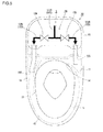
Fig. 2 is a lateral central cross-sectional view of the flush toilet bowl according to the first exemplary embodiment; -
Fig. 3 is a cross-sectional view showing the flush toilet bowl according to the first exemplary embodiment and a flow after the start of the toilet bowl cleaning and immediately before cleaning water discharged from a first water discharge port and cleaning water discharged from a second water discharge port join together; -
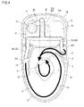
Fig. 4 is a cross-sectional view showing the flush toilet bowl according to the first exemplary embodiment, and a flow after the cleaning water discharged from the first water discharge port and the cleaning water discharged from the second water discharge port join together after the start of the toilet bowl cleaning; and -
Fig. 5 is a cross-sectional view showing a flush toilet bowl according to a second exemplary embodiment. - An explanation will be given regarding a preferred embodiment in the present invention.
- The flow of the cleaning water discharged from the first water discharge port is changed to flow downward when joining the cleaning water discharged from the second water discharge port and can form a mainstream that flows into the toilet drainage channel. In this case, the cleaning water discharged from the first water discharge port is intended to clean the surface of the toilet bowl portion and mainly flows in a swirling direction. Therefore, by joining the cleaning water discharged from the first water discharge port, the cleaning water discharged from the second water discharge port is capable of changing the flow of the cleaning water discharged from the first water discharge port to flow downward in the direction of the toilet drainage channel and form a mainstream of cleaning water flowing into the toilet drainage channel from one direction. Thus, this flush toilet bowl allows waste to be favorably conveyed into the toilet drainage channel and allows the waste to be discharged to the outside of the toilet bowl main body via the toilet drainage channel.
- The toilet bowl main body has a water supply chamber with the second water discharge port open toward the inside of the toilet bowl portion, and the toilet bowl cleaning device can have a water supply pipe through which cleaning water flows out that is placed inside the water supply chamber. In this case, the water supply chamber serves as a buffer space and is capable of delaying the timing at which the cleaning water discharged from the second water discharge port is increased to a set flow rate and delay the time for starting water discharge from the second water discharge port.
- The water supply pipe can allow cleaning water to flow out in a direction approximately opposite to that of the second water discharge port. In this case, the cleaning water flowing out from the water supplypipe can be prevented frombeing discharged to the inside of the toilet bowl portion directly through the second water discharge port. This allows the time for starting the water discharge from the second water discharge port to be delayed.
- The second water discharge port can have an opening area that is larger than that of an outlet port of the water supply pipe. In this case, the flow speed of the cleaning water discharged from the second water discharge port becomes lowered, and scattering of the cleaning water inside the toilet bowl portion can be prevented.
- Next, an explanation will be made regarding a first exemplary embodiment and a second exemplary embodiment in which a flush toilet bowl according to the present invention is embodied with reference to figures.
- As shown in
Figs. 1-4 , a flush toilet bowl according to the first exemplary embodiment is provided with a toilet bowlmain body 10, a toiletbowl cleaning device 20, and atoilet seat device 30. The toilet bowlmain body 10 has atoilet bowl portion 11, atoilet drainage channel 12, a firstwater discharge port 13, and a secondwater discharge port 14. The toiletbowl cleaning device 20 has acleaning tank 21, apump 22, and a watersupply distribution pipe 23. Thetoilet seat device 30 has: a toilet seat devicemain body 31 placed and fixed on the upper surface of the toilet bowlmain body 10; and a toilet seat and atoilet lid 32 that are rotatably and pivotably supported at the front of the toilet seat devicemain body 31. - The toilet bowl
main body 10 has aperipheral wall portion 15 that extends downward from the upper-surface periphery thereof. The toilet bowlmain body 10 forms atoilet bowl portion 11 on the front side thereof inside the peripheral wall portion 15 (the lower side inFig. 1 ) and forms a storage space S for storing the toiletbowl cleaning device 20 and the like below and behind the toilet bowl portion 11 (in the upper direction inFig. 1 ). Thetoilet drainage channel 12 connects to the downstream side of thetoilet bowl portion 11 and extends toward the rear part of thetoilet bowl portion 11. The toilet bowlmain body 10 has a water sealing portion formed by the lower part of thetoilet bowl portion 11 and thetoilet drainage channel 12 on an upstream side. In thetoilet drainage channel 12, adischarge outlet 12A, which is the downstream end of thetoilet drainage channel 12, is placed inside the storage space S behind thetoilet bowl portion 11. Thedischarge outlet 12A communicates with an inlet port that is open at the upper part of adrainpipe 50, which is drawn to a floor surface F via adrainage connecting pipe 40, inside the storage space S behind thetoilet bowl portion 11. - The toilet bowl
main body 10 has a firstwater supply chamber 16 provided outside the upper periphery portion on the left side of the toilet bowl portion 11 (the left side inFig. 1 ) and inside theperipheral wall portion 15. The firstwater supply chamber 16 extends backward from the approximate center part of thetoilet bowl portion 11 in the longitudinal direction (in the upward inFig. 1 ). An end portion of a left sidewater supply pipe 23L, which is described later, of the watersupply distribution pipe 23 is inserted frombehind the firstwater supply chamber 16 and placed inside the firstwater supply chamber 16. The firstwater discharge port 13 is provided in an open manner at a front end portion of the firstwater supply chamber 16. In other words, the firstwater discharge port 13 is in the upper periphery on the left side of thetoilet bowl portion 11 and is open toward the front direction at the approximate center part of thetoilet bowl portion 11 in the longitudinal direction (in the downward direction inFig. 1 ). The toilet bowlmain body 10 has arim water passage 18 connecting to the bottom surface of the firstwater discharge port 13 and formed at the upper periphery. - The toilet bowl
main body 10 has a secondwater supply chamber 17 provided outside the upper periphery portion on the right rear part of the toilet bowl portion 11 (the upper right part inFig. 1 ) and inside theperipheral wall portion 15. An endportion of a right-side water supplypipe 23R, which is described later, of the watersupply distribution pipe 23 is inserted from behind the secondwater supply chamber 17 and placed inside the secondwater supply chamber 17. The secondwater discharge port 14 is provided in an open manner in the rear part of a side surface of the secondwater supply chamber 17 on the side of thetoilet bowl portion 11. In other words, the secondwater discharge port 14 is in the upper periphery on the right rear part of thetoilet bowl portion 11 and is open toward the left direction (in the left direction inFig. 1 ). - A
cleaning tank 21 is in the storage space S and is placed below and behind thetoilet bowl portion 11. Thepump 22 is placed inside the storage space S behind thetoilet bowl portion 11 and above thecleaning tank 21. An inlet port of thepump 22 is connected to the upper end of thecleaning tank 21 via a connectingpipe 24. Thepump 22 connects adischarge pipe 25 to the watersupply distribution pipe 23. The watersupply distribution pipe 23 has: anupstream pipe 23A connected to thedischarge pipe 25 of thepump 22; and a left-side water supplypipe 23L and a right-sidewater supply pipe 23R branched from theupstream pipe 23A. - The left-side
water supply pipe 23L of the watersupply distribution pipe 23 has anoutlet port 23X with an open end. Cleaning water that has flowed out from theoutlet port 23X of the left-sidewater supply pipe 23L flows inside the firstwater supply chamber 16 toward the firstwater discharge port 13 and is discharged from the firstwater discharge port 13. The cleaning water discharged from the firstwater discharge port 13 flows along therim water passage 18 and forms a swirling flow swirling in a counterclockwise direction inside thetoilet bowl portion 11 in the planar view. - The right-
side water supplypipe 23R of the watersupply distribution pipe 23 has a closed end and has anoutlet port 23Y that is open on the side of theperipheral wall portion 15 of the secondwater supply chamber 17 on a side surface portion thereof. Theoutlet port 23Y of the right-sidewater supply pipe 23R allows cleaning water to flow out in a direction approximately opposite to that of the secondwater discharge port 14. Cleaning water that has flowed out from theoutlet port 23Y of the right-sidewater supply pipe 23R is discharged from the secondwater discharge port 14 while filling the inside of the secondwater supply chamber 17. The cleaning water discharged from the secondwater discharge port 14 joins the cleaning water discharged from the firstwater discharge port 13 in a merging point Z (seeFig. 4 ) and forms a downward flow toward thetoilet drainage channel 12. The secondwater discharge port 14 has an opening area that is larger than that of theoutlet port 23Y of the right-sidewater supply pipe 23R. Therefore, the flow speed of the cleaning water discharged from the secondwater discharge port 14 becomes lowered, and scattering of the cleaning water can be prevented when the cleaning water joins the cleaning water discharged from the firstwater discharge port 13 at the merging point Z inside thetoilet bowl portion 11, and so on. - An explanation will now be given regarding how cleaning water flows when toilet bowl cleaning is performed in a flush toilet bowl having such a structure.
- In this flush toilet bowl, when a toilet bowl cleaning switch provided on a remote controller (not shown) is operated, a
pump 22 is activated for a set period of time, and cleaning water stored in acleaning tank 21 is discharged from a firstwater discharge port 13 and a secondwater discharge port 14 via a watersupply distribution pipe 23. With this, this flush toilet bowl performs toilet bowl cleaning. - Since an
outlet port 23X of a left-sidewater supply pipe 23L of the watersupply distribution pipe 23 allows cleaning water to flow out toward the firstwater discharge port 13, this flush toilet bowl is capable of discharging cleaning water from the firstwater discharge port 13 along arim water passage 18 as shown inFig. 1 immediately after the start of the toilet bowl cleaning. Meanwhile, since anoutlet port 23Y of a right-sidewater supply pipe 23R of the watersupply distribution pipe 23 allows cleaning water to flow out in a direction approximately opposite to that of the secondwater discharge port 14, the flush toilet bowl does not discharge cleaning water inside thetoilet bowl portion 11 from the secondwater discharge port 14 immediately after the start of the toilet bowl cleaning. In other words, since theoutlet port 23Y of the right-sidewater supply pipe 23R allows cleaning water to flow out in the direction approximately opposite to that of the secondwater discharge port 14, the cleaning water flowing out from theoutlet port 23Y of the right-sidewater supply pipe 23R can be prevented from being discharged to the inside of thetoilet bowl portion 11 directly through the secondwater discharge port 14, and the time for starting the water discharge from the secondwater discharge port 14 can be delayed. - After that, with a short lapse of time, the cleaning water discharged from the first
water discharge port 13 flows to the right side of thetoilet bowl portion 11 along therim water passage 18 as shown inFig. 3 . On the other hand, the cleaning water that has flowed out from theoutlet port 23Y of the right-sidewater supply pipe 23R starts being gradually discharged from the secondwater discharge port 14. Until the secondwater supply chamber 17 is filled with the cleaning water that has flowed out from theoutlet port 23Y of the right-sidewater supply pipe 23R, the cleaning water discharged from the secondwater discharge port 14 is gradually increased. As described, the secondwater supply chamber 17 serves as a buffer space and is capable of delaying the timing at which the cleaning water discharged from the secondwater discharge port 14 is increased to a set flow rate (a peak flow rate, e.g., 25 L/min or more and desirably 35 L/min or more) and/or delay the time for starting water discharge from the secondwater discharge port 14. - After that, as shown in
Fig. 4 , by the time the cleaning water discharged from the firstwater discharge port 13 reaches the merging point Z, the secondwater supply chamber 17 is filled with the cleaning water that has flowed out from theoutlet port 23Y of the right-sidewater supply pipe 23R, the cleaning water discharged from the secondwater discharge port 14 is increased, and cleaning water of the set flow rate (peak flow rate) is discharged from the secondwater discharge port 14. In other words, the flush toilet bowl does not discharge a large amount of cleaning water from the secondwater discharge port 14 before the cleaning water discharged from the firstwater discharge port 13 reaches the merging point Z. Therefore, the flush toilet bowl is capable of suppressing the discharge of cleaning water that cannot be effectively used for toilet bowl cleaning from the secondwater discharge port 14 and is thus capable of saving water. Further, since the cleaning water discharged from the secondwater discharge port 14 is increased to the set flow rate (peak flow rate) when the cleaning water discharged from the firstwater discharge port 13 reaches the merging point Z in the flush toilet bowl, the cleaning water discharged from the secondwater discharge port 14 joins the cleaning water discharged from the firstwater discharge port 13, ensuring the formation of a downward flow toward thetoilet drainage channel 12. - Therefore, a flush toilet bowl according to the first exemplary embodiment is capable of efficiently performing toilet bowl cleaning.
- The flow of the cleaning water discharged from the first
water discharge port 13 is changed to a downward flow when joining the cleaning water discharged from the secondwater discharge port 14, forming a mainstream that flows into thetoilet drainage channel 12. In other words, the cleaning water discharged from the firstwater discharge port 13 is intended to clean the surface of thetoilet bowl portion 11 and mainly flows in a swirling direction. Therefore, by joining the cleaning water discharged from the firstwater discharge port 13, the cleaning water discharged from the secondwater discharge port 14 is capable of changing the flow of the cleaning water discharged from the firstwater discharge port 13 to flow downward in the direction of thetoilet drainage channel 12 and form a water flow of cleaning water flowing into thetoilet drainage channel 12 from one direction. Thus, this flush toilet bowl allows waste to be favorably conveyed into thetoilet drainage channel 12 and allows the waste to be discharged to the outside of the toilet bowlmain body 10 via thetoilet drainage channel 12. - A part of the cleaning water discharged from the first
water discharge port 13 joined by the cleaning water discharged from the secondwater discharge port 14 does not flow into thetoilet drainage channel 12 and forms a swirling flow swirling in the counterclockwise direction inside thetoilet bowl portion 11. After the set period of time is elapsed, the activation of thepump 22 is stopped, and the toilet bowl cleaning is ended. - <Second Exemplary Embodiment> As shown in
Fig. 5 , a flush toilet bowl according to a second exemplary embodiment is different from that of the first exemplary embodiment in that the flush toilet bowl according to the second exemplary embodiment connects a watersupply distribution pipe 123 of a toiletbowl cleaning device 120 directly to a water supply source (e.g., water pipe) so as to supply cleaning water to a firstwater discharge port 13 and a secondwater discharge port 14 using water supply pressure of the water supply source. The same reference numerals are assigned to the same configurations, and the detailed descriptions are omitted. - The toilet
bowl cleaning device 120 connects an upstream end of anupstream pipe 123A of the watersupply distribution pipe 123 to a water shutoff valve (not shown) connected to a water pipe that is drawn to a room in which this flush toilet bowl is installed. The toiletbowl cleaning device 120 has on-offvalves water supply pipe 123L and a right-sidewater supply pipe 123R branched from theupstreampipe 123A. These on-offvalves - An explanation will now be given regarding, in a flush toilet bowl provided with a toilet
bowl cleaning device 120 having such a structure, the operation of the toiletbowl cleaning device 120 and the way cleaning water flows when toilet bowl cleaning is performed. - In this flush toilet bowl, when a toilet bowl cleaning switch provided on a remote controller (not shown) is operated, an on-off
valve 124 provided in a left-sidewater supply pipe 123L is opened first. Therefore, the flush toilet bowl discharges cleaning water along arim water passage 18 from a firstwater discharge port 13, and the cleaning water flows toward a merging point Z where the cleaning water joins cleaning water discharged from a secondwater discharge port 14. - After that, an on-off
valve 125 provided in a right-sidewater supply pipe 23R is opened after a set period of time is elapsed. This allows the time for starting the water discharge from the secondwater discharge port 14 to be delayed. In other words, the flush toilet bowl is capable of discharging cleaning water from the secondwater discharge port 14 at the time when the cleaning water discharged from the firstwater discharge port 13 reaches the merging point Z where the cleaning water joins the cleaning water discharged from the secondwater discharge port 14. As described, since the flush toilet bowl does not discharge cleaning water from the secondwater discharge port 14 immediately after the start of toilet bowl cleaning, the flush toilet bowl is capable of suppressing the discharge of cleaning water that cannot be effectively used for the toilet bowl cleaning from the secondwater discharge port 14 and is thus capable of saving water. Further, since the flush toilet bowl is capable of discharging cleaning water from the secondwater discharge port 14 at a large flow rate when the cleaning water discharged from the firstwater discharge port 13 reaches the merging point Z, the cleaning water discharged from the secondwater discharge port 14 joins the cleaning water discharged from the firstwater discharge port 13, ensuring the formation of a downward flow toward atoilet drainage channel 12. - Therefore, a flush toilet bowl according to the second exemplary embodiment is capable of efficiently performing toilet bowl cleaning.
- In this flush toilet bowl, the flow of the cleaning water discharged from the first
water discharge port 13 is also changed to a downward flow when joining the cleaning water discharged from the secondwater discharge port 14, forming a mainstream that flows into thetoilet drainage channel 12. In other words, the cleaning water discharged from the firstwater discharge port 13 is intended to clean the surface of thetoilet bowl portion 11 and mainly flows in a swirling direction. Therefore, by joining the cleaning water discharged from the firstwater discharge port 13, the cleaning water discharged from the secondwater discharge port 14 is capable of changing the flow of the cleaning water discharged from the firstwater discharge port 13 to flow downward in the direction of thetoilet drainage channel 12 and form a water flow of cleaning water flowing into thetoilet drainage channel 12 from one direction. Thus, this flush toilet bowl allows waste to be favorably conveyed into thetoilet drainage channel 12 and allows the waste to be discharged to the outside of the toilet bowlmain body 10 via thetoilet drainage channel 12. - A part of the cleaning water discharged from the first
water discharge port 13 joined by the cleaning water discharged from the secondwater discharge port 14 does not flow into thetoilet drainage channel 12 and forms a swirling flow swirling in the counterclockwise direction inside thetoilet bowl portion 11. After the set period of time is elapsed, the on-off valve provided in the left-sidewater supply pipe 23L and the on-off valve provided in the right-sidewater supply pipe 23R are closed, and the toilet bowl cleaning is ended. - The present invention is not limited to the first and second exemplary embodiments explained according to the above descriptions and the figures, and, for example, the following exemplary embodiments are also included in the technical scope of the present invention. (1) In the first and second exemplary embodiments, the opening area of a second water discharge port is larger than that of an outlet port of a right-side water supply pipe. Alternatively, these opening areas may be equal. (2) In the first and second exemplary embodiments, a first water discharge port is placed on the left side of a toilet bowl portion and at an approximate center part of the toilet bowl portion in the longitudinal direction, and a second water discharge port is placed on the right rear part of the toilet bowl portion. Alternatively, the arrangement of the water discharge ports may be appropriately changed according to the respective shapes of the toilet bowl portion and a toilet drainage channel, a positional relationship thereof, and the like. (3) In the first exemplary embodiment, a cleaning tank is placed inside a storage space formed in a toilet bowl main body. Alternatively, the cleaning tank may be placed in a different place such as on a rear upper surface of the toilet bowl main body. (4) In the second exemplary embodiment, a second water supply chamber is provided. However, the second water supply chamber does not need to be provided. (5) In the second exemplary embodiment, an outlet port of a right-side water supply pipe is open on the side of a peripheral wall portion of a second water supply chamber such that cleaning water flows out in a direction approximately opposite to that of a second water discharge port. Alternatively, the outlet port of the right-side water supply pipe may be open toward the second water discharge port.
-
- 10
- toilet bowl main body
- 11
- toilet bowl portion
- 12
- toilet drainage channel
- 13
- first water discharge port
- 14
- second water discharge port
- 17
- second water supply chamber (water supply chamber)
- 20, 120
- toilet bowl cleaning device
- 23R, 123R
- right-side water supply pipe (water supply pipe)
- 23Y
- outlet port
- Z
- merging point
Claims (6)
- A flush toilet bowl comprising:a toilet bowl portion;a toilet drainage channel that communicates with the downstream side of the toilet bowl portion;a toilet bowl main body that includes : a first water discharge port that is open on the upper periphery of the toilet bowl portion and that discharges cleaning water that forms a swirling flow swirling inside the toilet bowl portion in the planar view; and a second water discharge port that is open on the upper periphery of the toilet bowl portion and discharges cleaning water that is joined, on the downstream side of the cleaning water discharged from the first water discharge port and flowing on the surface of the toilet bowl portion, by the cleaning water discharged from the first water discharge port and forms a downward flow toward the toilet drainage channel; anda toilet bowl cleaning device that supplies cleaning water to the first water discharge port and the second water discharge port,wherein, after the toilet bowl cleaning device starts supplying the cleaning water to the first water discharge port and the second water discharge port, and, by the time the cleaning water discharged from the first water discharge port flows on the surface of the toilet bowl portion and reaches a merging point where the cleaning water discharged from the first water discharge port joins the cleaning water discharged from the second water discharge port that forms the downward flow, the cleaning water discharged from the second water discharge port has been increased to a set flow rate.
- A flush toilet bowl comprising:a toilet bowl portion;a toilet drainage channel that communicates with the downstream side of the toilet bowl portion;a toilet bowl main body that includes : a first water discharge port that is open on the upper periphery of the toilet bowl portion and that discharges cleaning water that forms a swirling flow swirling inside the toilet bowl portion in the planar view; and a second water discharge port that is open on the upper periphery of the toilet bowl portion and discharges cleaning water that is joined, on the downstream side of the cleaning water discharged from the first water discharge port and flowing on the surface of the toilet bowl portion, by the cleaning water discharged from the first water discharge port and forms a downward flow toward the toilet drainage channel; anda toilet bowl cleaning device that supplies cleaning water to the first water discharge port and the second water discharge port such that the start of discharge of the cleaning water from the second water discharge port is delayed compared to the start of discharge of the cleaning water from the first water discharge port.
- The flush toilet bowl according to claim 1 or 2,
wherein the flow of the cleaning water discharged from the first water discharge port is changed to a downward flow when joining the cleaning water discharged from the second water discharge port, forming a mainstream that flows into the toilet drainage channel. - The flush toilet bowl according to claim 1 or 2,
wherein the toilet bowl main body has a water supply chamber with the second water discharge port open toward the inside of the toilet bowl portion, and
wherein the toilet bowl cleaning device has a water supply pipe through which cleaning water flows out that is placed inside the water supply chamber. - The flush toilet bowl according to claim 4,
wherein the water supply pipe allows cleaning water to flow out in a direction approximately opposite to that of the second water discharge port. - The flush toilet bowl according to claim 4,
wherein the second water discharge port has an opening area that is larger than that of an outlet port of the water supply pipe.
Applications Claiming Priority (2)
| Application Number | Priority Date | Filing Date | Title |
|---|---|---|---|
| JP2012180841A JP6006037B2 (en) | 2012-08-17 | 2012-08-17 | Flush toilet |
| PCT/JP2013/065886 WO2014027499A1 (en) | 2012-08-17 | 2013-06-07 | Flush toilet |
Publications (2)
| Publication Number | Publication Date |
|---|---|
| EP2894267A1 true EP2894267A1 (en) | 2015-07-15 |
| EP2894267A4 EP2894267A4 (en) | 2016-07-06 |
Family
ID=50286052
Family Applications (1)
| Application Number | Title | Priority Date | Filing Date |
|---|---|---|---|
| EP13879541.4A Withdrawn EP2894267A4 (en) | 2012-08-17 | 2013-06-07 | HUNTING TOILET |
Country Status (9)
| Country | Link |
|---|---|
| US (1) | US20150152628A1 (en) |
| EP (1) | EP2894267A4 (en) |
| JP (1) | JP6006037B2 (en) |
| CN (1) | CN104583501B (en) |
| CA (1) | CA2881752A1 (en) |
| HK (1) | HK1205543A1 (en) |
| PH (1) | PH12015500300A1 (en) |
| TW (1) | TW201408841A (en) |
| WO (1) | WO2014027499A1 (en) |
Families Citing this family (31)
| Publication number | Priority date | Publication date | Assignee | Title |
|---|---|---|---|---|
| CN103147499B (en) * | 2013-03-19 | 2015-04-08 | 青岛创惠实业有限公司 | Water flush seat urinal and extensible portable toilet thereof |
| US9719239B2 (en) * | 2014-03-18 | 2017-08-01 | Kohler India Corporation Private Limited | Dual-jet toilet |
| JP2016094762A (en) * | 2014-11-14 | 2016-05-26 | Toto株式会社 | Flush toilet bowl |
| JP6573066B2 (en) * | 2015-02-04 | 2019-09-11 | Toto株式会社 | Flush toilet |
| EP3269886A4 (en) * | 2015-03-09 | 2018-12-05 | Lixil Corporation | Flush toilet unit |
| JP6578572B2 (en) * | 2015-03-24 | 2019-09-25 | Toto株式会社 | Flush toilet |
| US20160289937A1 (en) * | 2015-03-31 | 2016-10-06 | Mansfield Plumbing Products, Llc | Primed siphonic flush toilet |
| CN104912169A (en) * | 2015-06-21 | 2015-09-16 | 唐山梦牌瓷业有限公司 | Rotating siphon type closestool |
| EP3321438B1 (en) * | 2015-07-08 | 2020-11-11 | LIXIL Corporation | Flush toilet device |
| JP6057241B1 (en) * | 2015-08-20 | 2017-01-11 | Toto株式会社 | Operation device for washing water tank device, washing water tank device provided with this operation device, and flush toilet equipped with this washing water tank device |
| JP6202476B2 (en) * | 2016-03-09 | 2017-09-27 | Toto株式会社 | Flush toilet |
| JP6793461B2 (en) * | 2016-03-31 | 2020-12-02 | 株式会社Lixil | Toilet bowl device |
| CN105821947B (en) * | 2016-05-18 | 2018-07-20 | 雅安市智力机械设备有限责任公司 | Folding toilet |
| US10151093B2 (en) * | 2016-07-27 | 2018-12-11 | Gene Quesada | Portable dialysis drainage system and method |
| JP6956943B2 (en) * | 2016-09-14 | 2021-11-02 | Toto株式会社 | Washing toilet bowl |
| WO2019008427A1 (en) * | 2017-07-07 | 2019-01-10 | 王昱坤 | Swirling flush and gas extraction toilet and deodorization method |
| CN107130669A (en) * | 2017-07-15 | 2017-09-05 | 浙江星星便洁宝有限公司 | The low pressure flushing system of intellectual water closet |
| TWI633990B (en) * | 2017-09-01 | 2018-09-01 | 和成欣業股份有限公司 | High pressure molding method and toilet body formed by using the same |
| CN107700621A (en) * | 2017-09-05 | 2018-02-16 | 王昱坤 | Hygienic device and eddy flow flushing and odor-exhausting closestool |
| JP6647685B2 (en) * | 2018-03-27 | 2020-02-14 | Toto株式会社 | Flush toilet |
| CN109372073A (en) * | 2018-11-11 | 2019-02-22 | 长沙源婕科技有限公司 | A kind of water-saving flush closestool |
| US11668085B2 (en) | 2019-02-28 | 2023-06-06 | Kohler Co. | Rim jet nozzle system for toilets |
| DE102019105732A1 (en) * | 2019-03-07 | 2020-09-10 | Duravit Aktiengesellschaft | Sanitary article in the form of a toilet |
| JP7095669B2 (en) * | 2019-09-30 | 2022-07-05 | Toto株式会社 | Washing toilet |
| JP2021071008A (en) * | 2019-10-31 | 2021-05-06 | 株式会社Lixil | Flush toilet |
| JP7352798B2 (en) * | 2019-12-24 | 2023-09-29 | パナソニックIpマネジメント株式会社 | flush toilet |
| JP7176581B2 (en) * | 2021-02-26 | 2022-11-22 | Toto株式会社 | flush toilet |
| CN116657723B (en) * | 2022-02-28 | 2026-04-07 | Toto株式会社 | Water-washable toilet |
| CN114592572B (en) * | 2022-03-15 | 2023-07-04 | 箭牌家居集团股份有限公司 | Hidden water outlet closestool |
| CN119855964A (en) * | 2022-09-22 | 2025-04-18 | 骊住株式会社 | Toilet device |
| JP7530944B2 (en) * | 2022-09-22 | 2024-08-08 | 株式会社Lixil | Toilet equipment |
Family Cites Families (13)
| Publication number | Priority date | Publication date | Assignee | Title |
|---|---|---|---|---|
| JP3216421B2 (en) * | 1994-05-31 | 2001-10-09 | 東陶機器株式会社 | Flush toilet |
| US5515556A (en) * | 1994-07-25 | 1996-05-14 | American Standard Inc. | Back jet flush toilet systems and methods |
| JPH11210051A (en) * | 1998-01-30 | 1999-08-03 | Inax Corp | Washing method by wash-off |
| CN100453748C (en) * | 1999-11-29 | 2009-01-21 | 株式会社伊奈 | tankless toilet |
| JP2001279791A (en) * | 2000-03-31 | 2001-10-10 | Toto Ltd | Flush toilet |
| US6715162B2 (en) * | 2002-08-30 | 2004-04-06 | American Standard Inc. | Toilet assembly |
| TW200636133A (en) * | 2005-02-10 | 2006-10-16 | Toto Ltd | Flushing type toilet |
| JP5299832B2 (en) * | 2007-03-27 | 2013-09-25 | Toto株式会社 | Flush toilet |
| US8151379B2 (en) * | 2007-05-07 | 2012-04-10 | Kohler Co. | Toilet with reduced water usage |
| JP5483314B2 (en) * | 2009-07-06 | 2014-05-07 | 株式会社Lixil | Toilet body |
| CN201502098U (en) * | 2009-08-28 | 2010-06-09 | 苏财彬 | Rotation type flushing closestool |
| JP5753662B2 (en) * | 2010-02-01 | 2015-07-22 | 株式会社Lixil | Flush toilet |
| JP5841343B2 (en) * | 2011-03-25 | 2016-01-13 | 株式会社Lixil | Flush toilet |
-
2012
- 2012-08-17 JP JP2012180841A patent/JP6006037B2/en active Active
-
2013
- 2013-06-07 EP EP13879541.4A patent/EP2894267A4/en not_active Withdrawn
- 2013-06-07 CA CA2881752A patent/CA2881752A1/en not_active Abandoned
- 2013-06-07 WO PCT/JP2013/065886 patent/WO2014027499A1/en not_active Ceased
- 2013-06-07 HK HK15106115.0A patent/HK1205543A1/en unknown
- 2013-06-07 CN CN201380043280.8A patent/CN104583501B/en not_active Expired - Fee Related
- 2013-07-08 TW TW102124373A patent/TW201408841A/en unknown
-
2015
- 2015-02-11 US US14/619,507 patent/US20150152628A1/en not_active Abandoned
- 2015-02-11 PH PH12015500300A patent/PH12015500300A1/en unknown
Also Published As
| Publication number | Publication date |
|---|---|
| TW201408841A (en) | 2014-03-01 |
| CN104583501A (en) | 2015-04-29 |
| PH12015500300A1 (en) | 2015-04-20 |
| JP2014037724A (en) | 2014-02-27 |
| US20150152628A1 (en) | 2015-06-04 |
| CA2881752A1 (en) | 2014-02-20 |
| WO2014027499A1 (en) | 2014-02-20 |
| HK1205543A1 (en) | 2015-12-18 |
| JP6006037B2 (en) | 2016-10-12 |
| EP2894267A4 (en) | 2016-07-06 |
| CN104583501B (en) | 2016-10-12 |
Similar Documents
| Publication | Publication Date | Title |
|---|---|---|
| US20150152628A1 (en) | Flush toilet bowl | |
| US8695126B2 (en) | Flush toilet with sloped surfaces for improved waste removal | |
| CN105189881B (en) | Rimless toilet | |
| JP6766119B2 (en) | Siphon type flush toilet flush valve for use in toilet bowl | |
| US12163325B2 (en) | Toilet with efficient water flow path | |
| JP2011208362A (en) | Water closet | |
| JP6425186B2 (en) | Flush toilet bowl | |
| JP6536773B2 (en) | Flush toilet bowl | |
| CN102918215B (en) | Toilet cleaning apparatus | |
| JP6414439B2 (en) | Flush toilet | |
| JP6168646B2 (en) | Toilet bowl cleaning device | |
| JP6029725B2 (en) | Toilet bowl cleaning device | |
| JP5815242B2 (en) | Toilet bowl cleaning device | |
| JP6547929B2 (en) | Flush toilet bowl | |
| JP2004116050A (en) | Flushing toilet bowl | |
| JP6752448B2 (en) | Water direct pressure flush toilet | |
| JP2010236201A (en) | Flush toilet bowl | |
| JP4207428B2 (en) | Toilet device | |
| JP2003261978A (en) | Closet bowl apparatus | |
| JP2016003453A (en) | Flush toilet | |
| JP6355068B2 (en) | Flush toilet equipment | |
| JP2011214277A (en) | Flush toilet bowl | |
| JP2024024058A5 (en) | ||
| KR20160033493A (en) | Water saving type toilet bowl | |
| JP2015036474A (en) | Water closet device |
Legal Events
| Date | Code | Title | Description |
|---|---|---|---|
| PUAI | Public reference made under article 153(3) epc to a published international application that has entered the european phase |
Free format text: ORIGINAL CODE: 0009012 |
|
| 17P | Request for examination filed |
Effective date: 20150210 |
|
| AK | Designated contracting states |
Kind code of ref document: A1 Designated state(s): AL AT BE BG CH CY CZ DE DK EE ES FI FR GB GR HR HU IE IS IT LI LT LU LV MC MK MT NL NO PL PT RO RS SE SI SK SM TR |
|
| AX | Request for extension of the european patent |
Extension state: BA ME |
|
| DAX | Request for extension of the european patent (deleted) | ||
| RA4 | Supplementary search report drawn up and despatched (corrected) |
Effective date: 20160607 |
|
| RIC1 | Information provided on ipc code assigned before grant |
Ipc: E03D 11/13 20060101ALI20160601BHEP Ipc: E03D 11/08 20060101AFI20160601BHEP |
|
| STAA | Information on the status of an ep patent application or granted ep patent |
Free format text: STATUS: THE APPLICATION HAS BEEN WITHDRAWN |
|
| 18W | Application withdrawn |
Effective date: 20161101 |