EP2893891B1 - Verschlusseinrichtung für kanülierte Knochenschrauben - Google Patents
Verschlusseinrichtung für kanülierte Knochenschrauben Download PDFInfo
- Publication number
- EP2893891B1 EP2893891B1 EP15150799.3A EP15150799A EP2893891B1 EP 2893891 B1 EP2893891 B1 EP 2893891B1 EP 15150799 A EP15150799 A EP 15150799A EP 2893891 B1 EP2893891 B1 EP 2893891B1
- Authority
- EP
- European Patent Office
- Prior art keywords
- opening
- central
- bone
- bone screw
- bone screws
- Prior art date
- Legal status (The legal status is an assumption and is not a legal conclusion. Google has not performed a legal analysis and makes no representation as to the accuracy of the status listed.)
- Active
Links
Images

Classifications
-
- A—HUMAN NECESSITIES
- A61—MEDICAL OR VETERINARY SCIENCE; HYGIENE
- A61B—DIAGNOSIS; SURGERY; IDENTIFICATION
- A61B17/00—Surgical instruments, devices or methods
- A61B17/56—Surgical instruments or methods for treatment of bones or joints; Devices specially adapted therefor
- A61B17/58—Surgical instruments or methods for treatment of bones or joints; Devices specially adapted therefor for osteosynthesis, e.g. bone plates, screws or setting implements
- A61B17/68—Internal fixation devices, including fasteners and spinal fixators, even if a part thereof projects from the skin
- A61B17/84—Fasteners therefor or fasteners being internal fixation devices
- A61B17/86—Pins or screws or threaded wires; nuts therefor
- A61B17/864—Pins or screws or threaded wires; nuts therefor hollow, e.g. with socket or cannulated
-
- A—HUMAN NECESSITIES
- A61—MEDICAL OR VETERINARY SCIENCE; HYGIENE
- A61B—DIAGNOSIS; SURGERY; IDENTIFICATION
- A61B17/00—Surgical instruments, devices or methods
- A61B17/56—Surgical instruments or methods for treatment of bones or joints; Devices specially adapted therefor
- A61B17/58—Surgical instruments or methods for treatment of bones or joints; Devices specially adapted therefor for osteosynthesis, e.g. bone plates, screws or setting implements
- A61B17/68—Internal fixation devices, including fasteners and spinal fixators, even if a part thereof projects from the skin
- A61B17/70—Spinal positioners or stabilisers, e.g. stabilisers comprising fluid filler in an implant
- A61B17/7097—Stabilisers comprising fluid filler in an implant, e.g. balloon; devices for inserting or filling such implants
- A61B17/7098—Stabilisers comprising fluid filler in an implant, e.g. balloon; devices for inserting or filling such implants wherein the implant is permeable or has openings, e.g. fenestrated screw
-
- A—HUMAN NECESSITIES
- A61—MEDICAL OR VETERINARY SCIENCE; HYGIENE
- A61B—DIAGNOSIS; SURGERY; IDENTIFICATION
- A61B17/00—Surgical instruments, devices or methods
- A61B17/56—Surgical instruments or methods for treatment of bones or joints; Devices specially adapted therefor
- A61B17/58—Surgical instruments or methods for treatment of bones or joints; Devices specially adapted therefor for osteosynthesis, e.g. bone plates, screws or setting implements
- A61B17/68—Internal fixation devices, including fasteners and spinal fixators, even if a part thereof projects from the skin
- A61B17/84—Fasteners therefor or fasteners being internal fixation devices
- A61B17/86—Pins or screws or threaded wires; nuts therefor
- A61B17/8625—Shanks, i.e. parts contacting bone tissue
- A61B17/8635—Tips of screws
-
- A—HUMAN NECESSITIES
- A61—MEDICAL OR VETERINARY SCIENCE; HYGIENE
- A61B—DIAGNOSIS; SURGERY; IDENTIFICATION
- A61B17/00—Surgical instruments, devices or methods
- A61B17/56—Surgical instruments or methods for treatment of bones or joints; Devices specially adapted therefor
- A61B17/58—Surgical instruments or methods for treatment of bones or joints; Devices specially adapted therefor for osteosynthesis, e.g. bone plates, screws or setting implements
- A61B17/68—Internal fixation devices, including fasteners and spinal fixators, even if a part thereof projects from the skin
- A61B17/84—Fasteners therefor or fasteners being internal fixation devices
- A61B17/86—Pins or screws or threaded wires; nuts therefor
- A61B17/8685—Pins or screws or threaded wires; nuts therefor comprising multiple separate parts
-
- A—HUMAN NECESSITIES
- A61—MEDICAL OR VETERINARY SCIENCE; HYGIENE
- A61B—DIAGNOSIS; SURGERY; IDENTIFICATION
- A61B90/00—Instruments, implements or accessories specially adapted for surgery or diagnosis and not covered by any of the groups A61B1/00 - A61B50/00, e.g. for luxation treatment or for protecting wound edges
- A61B90/03—Automatic limiting or abutting means, e.g. for safety
- A61B2090/037—Automatic limiting or abutting means, e.g. for safety with a frangible part, e.g. by reduced diameter
Definitions
- the invention relates to a device for unilateral closure of a cannulated opening in a bone screw.
- Osteoporosis is characterized by a decrease in the structural integrity of the bone. This often results in fractures, which largely affect the spine. Due to the reduced bone density, the clinical challenge is inadequate Anchoring stability in the supply of bone screws.
- Out DE 3508759 A1 is a bone screw known for the treatment of femur fractures.
- the invention describes a bone screw with a centrally arranged passage opening and a plurality of transverse openings. Through these openings, bone cement can be injected into the bone. As a result, a higher strength between bone screw and bone is achieved.
- Bone screws for stabilizing the spine which have a similar arrangement of openings for augmentation with bone cement. These proposed screws are closed at the distal end, so that extravertebral cement leakage at the distal end of the screw is prevented.
- the current trend in medical care is towards minimally invasive surgery.
- a requirement of this technique is the use of suitable target wires with which the position and orientation of bone screws can be predefined. Therefore, the bone screws must have a central through-hole, also called cannulation, to cope with the minimally invasive technique.
- a central through-hole also called cannulation
- cemented bone screws with a through-hole are used, there is a risk that the bone cement may be distributed outside the bone in the case of a bicortical screw connection.
- the object of the present invention is to provide a closure device for cementable bone screws, which is particularly suitable for the use of guidewires and thus for the minimally invasive technique.
- the problem to be solved is that bone cement unintentionally exits through the central through hole of the bone screw.
- the implant or implant system according to the invention should be inexpensive to produce since it is usually an instrument or implant for single use. Furthermore, the intra-operative handling should be easy.
- the closure device according to the invention should generally find its application in bone screws.
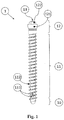
- a Pedikelschraubenschaft (1) will serve as an example of the different embodiments of the closure device ( FIG. 1 ).
- the pedicle screw shaft (1) consists of a distal (10), a middle (11) and a proximal component (12), wherein on the proximal component, a head part (121) is attached, which serves to connect the screw with a dorsal implant component eg a rod.
- An essential feature of the pedicle screw shaft (1) is a central passage opening (13). To this passage opening are radially arranged openings (111) which communicate with the central passage opening (13). Furthermore, the Pedikelschraubeschaft (1) has a bone thread (112).
- the closure device may preferably be designed as a sleeve (3) (closure tube) ( Figures 2 ).
- the sleeve (3) has a distal (31) and a proximal portion (35), at least one tongue (34) and a central passage opening (311).
- the sleeve can be provided with an anchoring area (32) and / or with an area for increasing the deformability (33) of the tongue (34).
- the sleeve (3) is located in Pedikelschraubenschaft (1) and has the function of a mechanically single-acting lock.
- Anchoring area (32) serves as a fixing device between Pedikelschraubenschaft (1) and sleeve (3). It secures the sleeve position in the pedicle screw shaft (1).
- the tongues (34) are shaped so as to close the central passage opening (311) in the unloaded state (3a).
- the tongues (34) are arranged such that they withstand an axial load from the proximal direction and obstruct access from the proximal to the distal end of the pedicle screw shaft (10). Thus, the distal pedicle screw end (10) is closed with a cement injection. If an axial load is taken from the distal direction (3b), the tongues (34) open, and the central passage opening (311) is released.
- a guide wire (14) can be guided through the pedicle screw shaft (1) ( Figure 3c ). The removal of the guide wire (14) closes the sleeve (3) again.
- the flexibility of the tongues (34) can be increased by a targeted material thickening, ablation and / or recess in the area (33).
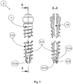
- the distal end (10) of the pedicle screw shaft (1) may be resiliently shaped to create a self-closing closure. This can be achieved by attaching at least one elastically deformable tongue (113) to the distal end (10) of the pedicle screw shaft (1).
- the tongue (113) for example, based on adjacent Sections (1131) can be realized.
- a notch (1132) on the distal end of the screw (10) may be used to facilitate insertion of the guidewire (14).
- the tongue (113) can be pre-bent.
Landscapes
- Health & Medical Sciences (AREA)
- Orthopedic Medicine & Surgery (AREA)
- Life Sciences & Earth Sciences (AREA)
- Surgery (AREA)
- Neurology (AREA)
- Heart & Thoracic Surgery (AREA)
- Engineering & Computer Science (AREA)
- Biomedical Technology (AREA)
- Nuclear Medicine, Radiotherapy & Molecular Imaging (AREA)
- Medical Informatics (AREA)
- Molecular Biology (AREA)
- Animal Behavior & Ethology (AREA)
- General Health & Medical Sciences (AREA)
- Public Health (AREA)
- Veterinary Medicine (AREA)
- Surgical Instruments (AREA)
Description
- Die Erfindung betrifft eine Einrichtung zum einseitigen Verschluss einer kanülierten Öffnung in einer Knochenschraube.
- Osteoporose ist durch eine Abnahme der strukturellen Integrität des Knochens gekennzeichnet. Häufig resultieren daraus Frakturen, welche zum großen Teil die Wirbelsäule betreffen. Aufgrund der reduzierten Knochendichte besteht die klinische Herausforderung in der unzureichenden Verankerungsstabilität bei der Versorgung mit Knochenschrauben.
- Aus
DE 3508759 A1 ist eine Knochenschraube für die Versorgung von Femurfrakturen bekannt. Die Erfindung beschreibt eine Knochenschraube mit einer mittig angeordneten Durchgangsöffnung sowie mehreren dazu querverlaufenden Öffnungen. Durch diese Öffnungen kann Knochenzement in den Knochen injiziert werden. Dadurch wird eine höhere Festigkeit zwischen Knochenschraube und Knochen erreicht. - Aus
WO 01/26568 A1 WO 2006/070961 A2 sind Knochenschrauben zur Stabilisierung der Wirbelsäule bekannt, welche eine vergleichbare Anordnung von Öffnungen für die Augmentation mit Knochenzement besitzen. Diese vorgestellten Schrauben sind am distalen Ende verschlossen, so dass ein extravertebraler Zementaustritt am distalen Schraubenende verhindert wird. - Der derzeitige Trend der medizinischen Versorgung geht in Richtung minimal-invasive Chirurgie. Eine Anforderung dieser Technik besteht in der Verwendung von geeigneten Zieldrähten mit denen die Position und Orientierung von Knochenschrauben vordefiniert werden kann. Deshalb müssen die Knochenschrauben eine zentrale Durchgangsöffnung, auch Kanülierung genannt, aufweisen, um der minimal-invasiven Technik gerecht zu werden. Werden zementierbare Knochenschrauben mit einer Durchgangsbohrung verwendet, besteht allerdings die Gefahr, dass bei einer bikortikalen Verschraubung sich der Knochenzement außerhalb vom Knochen verteilen kann.
- Aus
WO 00/28907 A1 - Aus
US 2010/030135 A1 undEP 2140824 A1 sind gattungsgemäße Knochenschrauben bekannt. - Die Aufgabe der vorliegenden Erfindung besteht darin, eine Verschlusseinrichtung für zementierbare Knochenschrauben zur Verfügung zu stellen, welche besonders für die Verwendung von Führungsdrähten und damit für die minimal-invasive Technik geeignet ist. Hierbei ist das Problem zu lösen, dass Knochenzement unbeabsichtigt durch die zentrale Durchgangsbohrung der Knochenschraube austritt. Das erfindungsgemäße Implantat bzw. Implantatsystem sollte kostengünstig in der Herstellung sein da es sich regelmäßig um ein Instrument bzw. Implantat zum Einmalgebrauch handelt. Ferner soll die intra-operative Handhabung einfach sein.
- Die Aufgabe wird erfindungsgemäß durch eine Knochenschraube mit den Merkmalen des Anspruchs 1 gelöst.
- Vorteilhaft bei der vorliegenden Erfindung ist die Reduktion des Herstellungsaufwands bzw. die Vereinfachung in der Handhabung. Mit der erfindungsgemäßen Verschlusseinrichtung kann die Zementapplikation bei Knochenschrauben sicherer und vor allem einfacher gestaltet werden.
- Die technischen Lösungen sind nachfolgend oft beispielhaft beschrieben. Dies soll als Mittel zur Erläuterung des zugrundeliegenden Gedankens aufgefasst und nicht als auf die jeweilige konkrete Darstellung beschränkt verstanden werden.
- Die erfindungsgemäße Verschlusseinrichtung soll generell bei Knochenschrauben Ihre Anwendung finden. In der weiteren Beschreibung wird ein Pedikelschraubenschaft (1) als Beispiel für die unterschiedlichen Ausführungsformen der Verschlusseinrichtung dienen (
Figur 1 ). Der Pedikelschraubenschaft (1) besteht aus einer distalen (10), einer mittleren (11) und einer proximalen Komponente (12), wobei an der proximalen Komponente ein Kopfteil (121) befestigt ist, welches dazu dient die Schraube mit einer dorsalen Implantatkomponente zu verbinden, z.B. einem Stab. - Auf die Funktion und Ausgestaltung des Schraubenschaftkopfes (12) wird in der folgenden Beschreibung nicht näher eingegangen. Ein wesentliches Merkmal des Pedikelschraubenschafts (1) ist eine zentrale Durchgangsöffnung (13). Zu dieser Durchgangsöffnung befinden sich radial angeordnete Öffnungen (111), die mit der zentralen Durchgangsöffnung (13) kommunizieren. Des Weiteren besitzt der Pedikelschraubeschaft (1) ein Knochengewinde (112).
- In einer Ausgestaltungsform der Erfindung kann die Verschlusseinrichtung vorzugsweise als Hülse (3) (Verschlussröhrchen) ausgeführt werden (
Figuren 2 ). Die Hülse (3) besitzt einen distalen (31) und einen proximalen Bereich (35), wenigstens eine Zunge (34) sowie eine zentrale Durchgangsöffnung (311). Optional kann die Hülse mit einem Verankerungsbereich (32) und/oder mit einem Bereich zur Steigerung der Deformierbarkeit (33) der Zunge (34) vorgesehen werden. Die Hülse (3) befindet sich im Pedikelschraubenschaft (1) und hat die Funktion einer mechanisch einseitig wirkenden Sperre. - Der
Verankerungsbereich (32) dient als Fixierungseinrichtung zwischen Pedikelschraubenschaft (1) und Hülse (3). Er sichert die Hülsenposition im Pedikelschraubenschaft (1). Die Zungen (34) sind so geformt, dass sie die zentrale Durchgangsöffnung (311) im unbelasteten Zustand (3a) verschließen. Dabei sind die Zungen (34) derart angeordnet, dass sie einer axialen Belastung aus proximaler Richtung standhalten und den Zugang vom proximalen zum distalen Ende des Pedikelschraubenschafts (10) versperren. So ist das distale Pedikelschraubenende (10) bei einer Zementinjektion verschlossen. Wird eine axiale Belastung aus distaler Richtung unternommen (3b) öffnen sich die Zungen (34), und die zentrale Durchgangsöffnung (311) wird freigegeben. So kann beispielsweise ein Führungsdraht (14) durch den Pedikelschraubenschaft (1) geführt werden (Figur 3c ). Das Entfernen des Führungsdrahts (14) verschließt die Hülse (3) wieder. - Die Flexibilität der Zungen (34) kann durch eine gezielte Materialandickung, -abtragung und/oder -aussparung im Bereich (33) erhöht werden.
- In einer weiteren Ausgestaltungsform der Erfindung gemäß
Figur 3 kann das distale Ende (10) des Pedikelschraubenschafts (1) elastisch geformt sein, um einen selbstständig schließenden Verschluss zu erzeugen. Dies kann dadurch erreicht werden, dass am distalen Ende (10) des Pedikelschraubenschafts (1) mindestens eine elastisch deformierbare Zunge (113) angebracht ist. Die Zunge (113) kann beispielsweise anhand benachbarter Schnitte (1131) realisiert werden. Optional kann eine Einkerbung (1132) am distalen Ende der Schraube (10) dazu verwendet werden, um die Einführung des Führungsdrahts (14) zu vereinfachen. Um die Anpresskraft der Zunge (113) gegenüber der Pedikelschraubenschaftinnenwandung zu erhöhen kann die Zunge (113) vorgebogen werden. -
-
Figur 1 zeigt einen Pedikelschraubenschaft als Stellvertreter für kanülierte Knochenschrauben. -
Figur 2 zeigt eine Ausführungsform mit einer Hülse mit auslenkbaren Zungen. -
Figur 3 zeigt eine weitere Ausgestaltungsform einer Knochenschraube, bei welcher die Verschlusseinrichtung bereits in der Schraube vorgesehen ist.
Claims (3)
- Knochenschraube mit einer zentralen Durchgangsöffnung (13), mindestens einer dazu radial verlaufenden und mit der zentralen Durchgangsöffnung kommunizierenden Öffnung (111) und einem distal befindlichen Verschluss der Durchgangsöffnung (13, 311), dadurch gekennzeichnet, dass der Verschluss aus mindestens einer federelastischen Zunge (34, 113) besteht, die so geformt ist, dass sie die zentrale Durchgangsöffnung (13, 311) im unbelasteten Zustand verschließt, und die derart schräg zur zentralen Durchgangsöffnung (13) der Knochenschraube angeordnet ist, dass sie einer axialen Belastung aus proximaler Richtung standhält und den Zugang vom proximalen zum distalen Ende versperrt, die zentrale Durchgangsöffnung (13, 311) jedoch bei axialer Belastung aus distaler Richtung freigibt.
- Knochenschraube gemäß Anspruch 1, dadurch gekennzeichnet, dass die Zunge (34) so geformt und schräg zur zentralen Durchgangsöffnung (13) der Knochenschraube angeordnet ist, dass sie durch Einführen eines Führungsdrahtes (14) aus distaler Richtung radial ausweichen kann.
- Knochenschraube gemäß den Ansprüchen 1 und 2, dadurch gekennzeichnet, dass sich die Zunge (34) an einer Hülse (3) als Träger befindet, und sich die Hülse (3) am distalen Ende der zentralen Durchgangsöffnung (13) der Knochenschraube befindet.
Applications Claiming Priority (2)
| Application Number | Priority Date | Filing Date | Title |
|---|---|---|---|
| DE201110017602 DE102011017602B4 (de) | 2011-04-27 | 2011-04-27 | Knochenschraube mit Verschlusseinrichtung |
| EP12766903.4A EP2701622B1 (de) | 2011-04-27 | 2012-04-27 | Verschlusseinrichtung für kanülierte knochenschrauben |
Related Parent Applications (2)
| Application Number | Title | Priority Date | Filing Date |
|---|---|---|---|
| EP12766903.4A Division EP2701622B1 (de) | 2011-04-27 | 2012-04-27 | Verschlusseinrichtung für kanülierte knochenschrauben |
| EP12766903.4A Division-Into EP2701622B1 (de) | 2011-04-27 | 2012-04-27 | Verschlusseinrichtung für kanülierte knochenschrauben |
Publications (2)
| Publication Number | Publication Date |
|---|---|
| EP2893891A1 EP2893891A1 (de) | 2015-07-15 |
| EP2893891B1 true EP2893891B1 (de) | 2017-01-11 |
Family
ID=46968148
Family Applications (2)
| Application Number | Title | Priority Date | Filing Date |
|---|---|---|---|
| EP15150799.3A Active EP2893891B1 (de) | 2011-04-27 | 2012-04-27 | Verschlusseinrichtung für kanülierte Knochenschrauben |
| EP12766903.4A Active EP2701622B1 (de) | 2011-04-27 | 2012-04-27 | Verschlusseinrichtung für kanülierte knochenschrauben |
Family Applications After (1)
| Application Number | Title | Priority Date | Filing Date |
|---|---|---|---|
| EP12766903.4A Active EP2701622B1 (de) | 2011-04-27 | 2012-04-27 | Verschlusseinrichtung für kanülierte knochenschrauben |
Country Status (3)
| Country | Link |
|---|---|
| EP (2) | EP2893891B1 (de) |
| DE (1) | DE102011017602B4 (de) |
| WO (1) | WO2012146744A2 (de) |
Families Citing this family (6)
| Publication number | Priority date | Publication date | Assignee | Title |
|---|---|---|---|---|
| CN103110453B (zh) * | 2013-03-05 | 2015-11-25 | 吴志宏 | 一种骨水泥螺钉及其制备方法 |
| CN103845110B (zh) * | 2014-03-19 | 2015-12-02 | 中国人民解放军第四军医大学 | 一种用于骨质条件不佳的多功能骨螺钉 |
| US10993748B2 (en) | 2015-09-30 | 2021-05-04 | Koninklijke Philips N.V. | System for implanting in bone tissue |
| EP4023178B1 (de) | 2016-02-25 | 2023-11-29 | Biedermann Technologies GmbH & Co. KG | Knochenanker |
| DE102020003320A1 (de) * | 2020-06-03 | 2021-12-09 | MIMEO MEDlCAL GmbH | Knochenanker für die optimierte Zementapplikation |
| DE102020005927A1 (de) * | 2020-09-28 | 2022-03-31 | Mimeo Medical Gmbh | Knochenanker für die optimierte Zementapplikation |
Family Cites Families (14)
| Publication number | Priority date | Publication date | Assignee | Title |
|---|---|---|---|---|
| DE1500015A1 (de) * | 1965-09-09 | 1969-05-14 | Kurt Ehmann | Ventil fuer Kolbenkompressoren |
| CA1227902A (en) | 1984-04-02 | 1987-10-13 | Raymond G. Tronzo | Fenestrated hip screw and method of augmented internal fixation |
| US4860513A (en) | 1988-01-25 | 1989-08-29 | Whitman Robert E | Roofing fastener |
| US6214012B1 (en) | 1998-11-13 | 2001-04-10 | Harrington Arthritis Research Center | Method and apparatus for delivering material to a desired location |
| DE19949285C2 (de) | 1999-10-12 | 2002-08-14 | Impag Gmbh Medizintechnik | Knochenschraube |
| EP1835859A2 (de) | 2004-12-31 | 2007-09-26 | Ji-Hoon Her | Stielschraube und vorrichtung zur injektion von knochenzement in knochen |
| WO2006108329A1 (fr) * | 2005-04-12 | 2006-10-19 | Wei Liang | Procede medical de fixation a un os et sa vis |
| KR101145415B1 (ko) * | 2005-07-08 | 2012-05-15 | 비이더만 모테크 게엠베하 & 코. 카게 | 뼈 고정 요소 |
| US8821506B2 (en) | 2006-05-11 | 2014-09-02 | Michael David Mitchell | Bone screw |
| US20070293866A1 (en) * | 2006-05-12 | 2007-12-20 | Dieter Stoeckel | Bone anchor system and method of use |
| CA2693395C (en) * | 2007-07-13 | 2012-11-06 | Stryker Trauma Gmbh | Device for fixation of bone fractures |
| EP2687173B1 (de) | 2008-07-01 | 2017-05-03 | Biedermann Technologies GmbH & Co. KG | Kanülierter Knochenanker mit Stopfen und Werkzeug zur Einführung des Stopfens in den Knochenanker |
| US8403973B2 (en) * | 2008-08-05 | 2013-03-26 | The University Of Toledo | Pedicle screw assembly having a retractable screw tip for facilitating the securement of the pedicle screw assembly to a spinal vertebra |
| EP2427119B1 (de) * | 2009-05-06 | 2013-08-21 | Woodwelding AG | Vorrichtung zur abgabe eines materials mit thermoplastischen eigenschaften in einem fliessfähigen zustand an einer operationsstelle in einem menschlichen oder tierischen patienten |
-
2011
- 2011-04-27 DE DE201110017602 patent/DE102011017602B4/de active Active
-
2012
- 2012-04-27 EP EP15150799.3A patent/EP2893891B1/de active Active
- 2012-04-27 EP EP12766903.4A patent/EP2701622B1/de active Active
- 2012-04-27 WO PCT/EP2012/057820 patent/WO2012146744A2/de not_active Ceased
Non-Patent Citations (1)
| Title |
|---|
| None * |
Also Published As
| Publication number | Publication date |
|---|---|
| DE102011017602A1 (de) | 2012-10-31 |
| EP2701622A2 (de) | 2014-03-05 |
| EP2893891A1 (de) | 2015-07-15 |
| DE102011017602B4 (de) | 2015-05-07 |
| EP2701622B1 (de) | 2015-03-04 |
| WO2012146744A3 (de) | 2013-05-02 |
| WO2012146744A2 (de) | 2012-11-01 |
Similar Documents
| Publication | Publication Date | Title |
|---|---|---|
| EP1753355B1 (de) | Knochenschraube mit gelenk | |
| DE602004011613T2 (de) | Wirbel-osteosynthese-gerät | |
| DE102006056950B4 (de) | Orthopädische Zugschraube zur Osteosynthese und/oder Fixation von Knochensegmenten | |
| DE69915254T2 (de) | Knochenschraube für orthopädische Chirurgie | |
| EP2263584B1 (de) | Marknagel mit Verriegelungsschraube | |
| EP2667820B1 (de) | Zahnersatz-system | |
| EP2893891A1 (de) | Verschlusseinrichtung für kanülierte Knochenschrauben | |
| EP2468216B1 (de) | Implantierbare Prothese zum Ersatz des menschlichen Hüft- oder Kniegelenks und der angrenzenden Knochenabschnitte | |
| EP2674127B1 (de) | Implantat | |
| EP2564799A1 (de) | Chirurgischer Mittelfuß-Kompressionsnagel | |
| DE102008017741A1 (de) | Vorrichtung zur Stabilisierung von Röhrenknochenbrüchen | |
| DE102013001933B4 (de) | Knochenschraube zur Fixation eines Knochenschrauben-Stabsystems | |
| EP2446842B1 (de) | Vorrichtung zum Stabilisieren einer Wirbelsäule | |
| EP2368518B1 (de) | Abformkappe für ein Dentalimplantat | |
| DE202008016697U1 (de) | Implantatschraube | |
| DE202012009023U1 (de) | Knochenschraube zur Fixation eines Knochenschrauben-Stabsystems | |
| EP2196165A1 (de) | Instrument zum Lösen eines Schraubenstumpfes einer Verbindungsschraube eines Zahnimplantats | |
| DE102007029090A1 (de) | Vorrichtung zur Osteosynthese gelenknaher Knochenfrakturen | |
| EP2129311A1 (de) | Manipulator für rundmaterial, insbesondere für einen kirschnerdraht | |
| WO2008129401A1 (de) | Kompressionsschraube mit drahtelement | |
| DE102021105353B4 (de) | Absperrhahn, Gehäuse eines Absperrhahns sowie Verfahren zur Herstellung eines Gehäuses eines Absperrhahns | |
| WO2014111134A1 (de) | Mtv-implantations-set | |
| DE102006007541A1 (de) | Implantat für Zahnersatzbefestigung | |
| CH699196B1 (de) | Implantatschraube. | |
| DE102010023640B4 (de) | Nagel-Schrauben-System für winkelstabile Osteosynthese |
Legal Events
| Date | Code | Title | Description |
|---|---|---|---|
| PUAI | Public reference made under article 153(3) epc to a published international application that has entered the european phase |
Free format text: ORIGINAL CODE: 0009012 |
|
| 17P | Request for examination filed |
Effective date: 20150112 |
|
| AC | Divisional application: reference to earlier application |
Ref document number: 2701622 Country of ref document: EP Kind code of ref document: P |
|
| AK | Designated contracting states |
Kind code of ref document: A1 Designated state(s): AL AT BE BG CH CY CZ DE DK EE ES FI FR GB GR HR HU IE IS IT LI LT LU LV MC MK MT NL NO PL PT RO RS SE SI SK SM TR |
|
| R17P | Request for examination filed (corrected) |
Effective date: 20151006 |
|
| RBV | Designated contracting states (corrected) |
Designated state(s): AL AT BE BG CH CY CZ DE DK EE ES FI FR GB GR HR HU IE IS IT LI LT LU LV MC MK MT NL NO PL PT RO RS SE SI SK SM TR |
|
| GRAP | Despatch of communication of intention to grant a patent |
Free format text: ORIGINAL CODE: EPIDOSNIGR1 |
|
| RIC1 | Information provided on ipc code assigned before grant |
Ipc: A61B 90/00 20160101ALI20160708BHEP Ipc: A61B 17/86 20060101AFI20160708BHEP Ipc: A61B 17/70 20060101ALI20160708BHEP |
|
| INTG | Intention to grant announced |
Effective date: 20160802 |
|
| GRAS | Grant fee paid |
Free format text: ORIGINAL CODE: EPIDOSNIGR3 |
|
| GRAA | (expected) grant |
Free format text: ORIGINAL CODE: 0009210 |
|
| AC | Divisional application: reference to earlier application |
Ref document number: 2701622 Country of ref document: EP Kind code of ref document: P |
|
| AK | Designated contracting states |
Kind code of ref document: B1 Designated state(s): AL AT BE BG CH CY CZ DE DK EE ES FI FR GB GR HR HU IE IS IT LI LT LU LV MC MK MT NL NO PL PT RO RS SE SI SK SM TR |
|
| REG | Reference to a national code |
Ref country code: GB Ref legal event code: FG4D Free format text: NOT ENGLISH |
|
| REG | Reference to a national code |
Ref country code: CH Ref legal event code: EP |
|
| REG | Reference to a national code |
Ref country code: AT Ref legal event code: REF Ref document number: 860534 Country of ref document: AT Kind code of ref document: T Effective date: 20170115 |
|
| REG | Reference to a national code |
Ref country code: IE Ref legal event code: FG4D Free format text: LANGUAGE OF EP DOCUMENT: GERMAN |
|
| REG | Reference to a national code |
Ref country code: DE Ref legal event code: R096 Ref document number: 502012009338 Country of ref document: DE |
|
| REG | Reference to a national code |
Ref country code: NL Ref legal event code: FP |
|
| REG | Reference to a national code |
Ref country code: LT Ref legal event code: MG4D |
|
| PG25 | Lapsed in a contracting state [announced via postgrant information from national office to epo] |
Ref country code: GR Free format text: LAPSE BECAUSE OF FAILURE TO SUBMIT A TRANSLATION OF THE DESCRIPTION OR TO PAY THE FEE WITHIN THE PRESCRIBED TIME-LIMIT Effective date: 20170412 Ref country code: NO Free format text: LAPSE BECAUSE OF FAILURE TO SUBMIT A TRANSLATION OF THE DESCRIPTION OR TO PAY THE FEE WITHIN THE PRESCRIBED TIME-LIMIT Effective date: 20170411 Ref country code: FI Free format text: LAPSE BECAUSE OF FAILURE TO SUBMIT A TRANSLATION OF THE DESCRIPTION OR TO PAY THE FEE WITHIN THE PRESCRIBED TIME-LIMIT Effective date: 20170111 Ref country code: HR Free format text: LAPSE BECAUSE OF FAILURE TO SUBMIT A TRANSLATION OF THE DESCRIPTION OR TO PAY THE FEE WITHIN THE PRESCRIBED TIME-LIMIT Effective date: 20170111 Ref country code: IS Free format text: LAPSE BECAUSE OF FAILURE TO SUBMIT A TRANSLATION OF THE DESCRIPTION OR TO PAY THE FEE WITHIN THE PRESCRIBED TIME-LIMIT Effective date: 20170511 Ref country code: LT Free format text: LAPSE BECAUSE OF FAILURE TO SUBMIT A TRANSLATION OF THE DESCRIPTION OR TO PAY THE FEE WITHIN THE PRESCRIBED TIME-LIMIT Effective date: 20170111 |
|
| PG25 | Lapsed in a contracting state [announced via postgrant information from national office to epo] |
Ref country code: BG Free format text: LAPSE BECAUSE OF FAILURE TO SUBMIT A TRANSLATION OF THE DESCRIPTION OR TO PAY THE FEE WITHIN THE PRESCRIBED TIME-LIMIT Effective date: 20170411 Ref country code: PL Free format text: LAPSE BECAUSE OF FAILURE TO SUBMIT A TRANSLATION OF THE DESCRIPTION OR TO PAY THE FEE WITHIN THE PRESCRIBED TIME-LIMIT Effective date: 20170111 Ref country code: RS Free format text: LAPSE BECAUSE OF FAILURE TO SUBMIT A TRANSLATION OF THE DESCRIPTION OR TO PAY THE FEE WITHIN THE PRESCRIBED TIME-LIMIT Effective date: 20170111 Ref country code: LV Free format text: LAPSE BECAUSE OF FAILURE TO SUBMIT A TRANSLATION OF THE DESCRIPTION OR TO PAY THE FEE WITHIN THE PRESCRIBED TIME-LIMIT Effective date: 20170111 Ref country code: SE Free format text: LAPSE BECAUSE OF FAILURE TO SUBMIT A TRANSLATION OF THE DESCRIPTION OR TO PAY THE FEE WITHIN THE PRESCRIBED TIME-LIMIT Effective date: 20170111 Ref country code: ES Free format text: LAPSE BECAUSE OF FAILURE TO SUBMIT A TRANSLATION OF THE DESCRIPTION OR TO PAY THE FEE WITHIN THE PRESCRIBED TIME-LIMIT Effective date: 20170111 Ref country code: PT Free format text: LAPSE BECAUSE OF FAILURE TO SUBMIT A TRANSLATION OF THE DESCRIPTION OR TO PAY THE FEE WITHIN THE PRESCRIBED TIME-LIMIT Effective date: 20170511 |
|
| REG | Reference to a national code |
Ref country code: DE Ref legal event code: R097 Ref document number: 502012009338 Country of ref document: DE |
|
| PG25 | Lapsed in a contracting state [announced via postgrant information from national office to epo] |
Ref country code: CZ Free format text: LAPSE BECAUSE OF FAILURE TO SUBMIT A TRANSLATION OF THE DESCRIPTION OR TO PAY THE FEE WITHIN THE PRESCRIBED TIME-LIMIT Effective date: 20170111 Ref country code: EE Free format text: LAPSE BECAUSE OF FAILURE TO SUBMIT A TRANSLATION OF THE DESCRIPTION OR TO PAY THE FEE WITHIN THE PRESCRIBED TIME-LIMIT Effective date: 20170111 Ref country code: SK Free format text: LAPSE BECAUSE OF FAILURE TO SUBMIT A TRANSLATION OF THE DESCRIPTION OR TO PAY THE FEE WITHIN THE PRESCRIBED TIME-LIMIT Effective date: 20170111 Ref country code: RO Free format text: LAPSE BECAUSE OF FAILURE TO SUBMIT A TRANSLATION OF THE DESCRIPTION OR TO PAY THE FEE WITHIN THE PRESCRIBED TIME-LIMIT Effective date: 20170111 |
|
| PLBE | No opposition filed within time limit |
Free format text: ORIGINAL CODE: 0009261 |
|
| STAA | Information on the status of an ep patent application or granted ep patent |
Free format text: STATUS: NO OPPOSITION FILED WITHIN TIME LIMIT |
|
| PG25 | Lapsed in a contracting state [announced via postgrant information from national office to epo] |
Ref country code: DK Free format text: LAPSE BECAUSE OF FAILURE TO SUBMIT A TRANSLATION OF THE DESCRIPTION OR TO PAY THE FEE WITHIN THE PRESCRIBED TIME-LIMIT Effective date: 20170111 Ref country code: SM Free format text: LAPSE BECAUSE OF FAILURE TO SUBMIT A TRANSLATION OF THE DESCRIPTION OR TO PAY THE FEE WITHIN THE PRESCRIBED TIME-LIMIT Effective date: 20170111 |
|
| REG | Reference to a national code |
Ref country code: CH Ref legal event code: PL |
|
| 26N | No opposition filed |
Effective date: 20171012 |
|
| REG | Reference to a national code |
Ref country code: IE Ref legal event code: MM4A |
|
| REG | Reference to a national code |
Ref country code: FR Ref legal event code: ST Effective date: 20171229 |
|
| PG25 | Lapsed in a contracting state [announced via postgrant information from national office to epo] |
Ref country code: MC Free format text: LAPSE BECAUSE OF FAILURE TO SUBMIT A TRANSLATION OF THE DESCRIPTION OR TO PAY THE FEE WITHIN THE PRESCRIBED TIME-LIMIT Effective date: 20170111 Ref country code: FR Free format text: LAPSE BECAUSE OF NON-PAYMENT OF DUE FEES Effective date: 20170502 |
|
| PG25 | Lapsed in a contracting state [announced via postgrant information from national office to epo] |
Ref country code: CH Free format text: LAPSE BECAUSE OF NON-PAYMENT OF DUE FEES Effective date: 20170430 Ref country code: LI Free format text: LAPSE BECAUSE OF NON-PAYMENT OF DUE FEES Effective date: 20170430 Ref country code: LU Free format text: LAPSE BECAUSE OF NON-PAYMENT OF DUE FEES Effective date: 20170427 Ref country code: SI Free format text: LAPSE BECAUSE OF FAILURE TO SUBMIT A TRANSLATION OF THE DESCRIPTION OR TO PAY THE FEE WITHIN THE PRESCRIBED TIME-LIMIT Effective date: 20170111 |
|
| REG | Reference to a national code |
Ref country code: BE Ref legal event code: MM Effective date: 20170430 |
|
| PG25 | Lapsed in a contracting state [announced via postgrant information from national office to epo] |
Ref country code: IE Free format text: LAPSE BECAUSE OF NON-PAYMENT OF DUE FEES Effective date: 20170427 |
|
| PG25 | Lapsed in a contracting state [announced via postgrant information from national office to epo] |
Ref country code: BE Free format text: LAPSE BECAUSE OF NON-PAYMENT OF DUE FEES Effective date: 20170430 |
|
| PG25 | Lapsed in a contracting state [announced via postgrant information from national office to epo] |
Ref country code: MT Free format text: LAPSE BECAUSE OF FAILURE TO SUBMIT A TRANSLATION OF THE DESCRIPTION OR TO PAY THE FEE WITHIN THE PRESCRIBED TIME-LIMIT Effective date: 20170111 |
|
| PG25 | Lapsed in a contracting state [announced via postgrant information from national office to epo] |
Ref country code: HU Free format text: LAPSE BECAUSE OF FAILURE TO SUBMIT A TRANSLATION OF THE DESCRIPTION OR TO PAY THE FEE WITHIN THE PRESCRIBED TIME-LIMIT; INVALID AB INITIO Effective date: 20120427 |
|
| PGFP | Annual fee paid to national office [announced via postgrant information from national office to epo] |
Ref country code: NL Payment date: 20190418 Year of fee payment: 8 |
|
| PGFP | Annual fee paid to national office [announced via postgrant information from national office to epo] |
Ref country code: PT Payment date: 20190227 Year of fee payment: 11 |
|
| PG25 | Lapsed in a contracting state [announced via postgrant information from national office to epo] |
Ref country code: CY Free format text: LAPSE BECAUSE OF FAILURE TO SUBMIT A TRANSLATION OF THE DESCRIPTION OR TO PAY THE FEE WITHIN THE PRESCRIBED TIME-LIMIT Effective date: 20170111 |
|
| PG25 | Lapsed in a contracting state [announced via postgrant information from national office to epo] |
Ref country code: MK Free format text: LAPSE BECAUSE OF FAILURE TO SUBMIT A TRANSLATION OF THE DESCRIPTION OR TO PAY THE FEE WITHIN THE PRESCRIBED TIME-LIMIT Effective date: 20170111 |
|
| PG25 | Lapsed in a contracting state [announced via postgrant information from national office to epo] |
Ref country code: TR Free format text: LAPSE BECAUSE OF FAILURE TO SUBMIT A TRANSLATION OF THE DESCRIPTION OR TO PAY THE FEE WITHIN THE PRESCRIBED TIME-LIMIT Effective date: 20170111 |
|
| PG25 | Lapsed in a contracting state [announced via postgrant information from national office to epo] |
Ref country code: AL Free format text: LAPSE BECAUSE OF FAILURE TO SUBMIT A TRANSLATION OF THE DESCRIPTION OR TO PAY THE FEE WITHIN THE PRESCRIBED TIME-LIMIT Effective date: 20170111 |
|
| REG | Reference to a national code |
Ref country code: NL Ref legal event code: MM Effective date: 20200501 |
|
| REG | Reference to a national code |
Ref country code: AT Ref legal event code: MM01 Ref document number: 860534 Country of ref document: AT Kind code of ref document: T Effective date: 20200427 |
|
| PG25 | Lapsed in a contracting state [announced via postgrant information from national office to epo] |
Ref country code: AT Free format text: LAPSE BECAUSE OF NON-PAYMENT OF DUE FEES Effective date: 20200427 |
|
| PG25 | Lapsed in a contracting state [announced via postgrant information from national office to epo] |
Ref country code: NL Free format text: LAPSE BECAUSE OF NON-PAYMENT OF DUE FEES Effective date: 20200501 |
|
| PG25 | Lapsed in a contracting state [announced via postgrant information from national office to epo] |
Ref country code: IT Free format text: LAPSE BECAUSE OF NON-PAYMENT OF DUE FEES Effective date: 20200427 |
|
| P01 | Opt-out of the competence of the unified patent court (upc) registered |
Effective date: 20230505 |
|
| PGFP | Annual fee paid to national office [announced via postgrant information from national office to epo] |
Ref country code: DE Payment date: 20250611 Year of fee payment: 14 |
|
| PGFP | Annual fee paid to national office [announced via postgrant information from national office to epo] |
Ref country code: GB Payment date: 20250415 Year of fee payment: 14 |