EP2893296B1 - Vestibuläres implantat mit einem hybriden mems mikrofluidischen gyroskop - Google Patents
Vestibuläres implantat mit einem hybriden mems mikrofluidischen gyroskop Download PDFInfo
- Publication number
- EP2893296B1 EP2893296B1 EP13812069.6A EP13812069A EP2893296B1 EP 2893296 B1 EP2893296 B1 EP 2893296B1 EP 13812069 A EP13812069 A EP 13812069A EP 2893296 B1 EP2893296 B1 EP 2893296B1
- Authority
- EP
- European Patent Office
- Prior art keywords
- fluid
- enclosure
- sensing
- gyroscope
- piezo
- Prior art date
- Legal status (The legal status is an assumption and is not a legal conclusion. Google has not performed a legal analysis and makes no representation as to the accuracy of the status listed.)
- Not-in-force
Links
- 239000007943 implant Substances 0.000 title claims description 19
- 230000001720 vestibular Effects 0.000 title claims description 18
- 239000012530 fluid Substances 0.000 claims description 58
- 239000011521 glass Substances 0.000 claims description 8
- 229910052710 silicon Inorganic materials 0.000 claims description 8
- 239000010703 silicon Substances 0.000 claims description 8
- 238000005530 etching Methods 0.000 claims description 6
- 238000003754 machining Methods 0.000 claims description 6
- 210000002768 hair cell Anatomy 0.000 claims description 5
- 231100000252 nontoxic Toxicity 0.000 claims description 5
- 230000003000 nontoxic effect Effects 0.000 claims description 5
- XLYOFNOQVPJJNP-UHFFFAOYSA-N water Substances O XLYOFNOQVPJJNP-UHFFFAOYSA-N 0.000 claims description 3
- DGAQECJNVWCQMB-PUAWFVPOSA-M Ilexoside XXIX Chemical compound C[C@@H]1CC[C@@]2(CC[C@@]3(C(=CC[C@H]4[C@]3(CC[C@@H]5[C@@]4(CC[C@@H](C5(C)C)OS(=O)(=O)[O-])C)C)[C@@H]2[C@]1(C)O)C)C(=O)O[C@H]6[C@@H]([C@H]([C@@H]([C@H](O6)CO)O)O)O.[Na+] DGAQECJNVWCQMB-PUAWFVPOSA-M 0.000 claims description 2
- 239000007788 liquid Substances 0.000 claims description 2
- 229910052708 sodium Inorganic materials 0.000 claims description 2
- 239000011734 sodium Substances 0.000 claims description 2
- 239000002195 soluble material Substances 0.000 claims 1
- 239000000463 material Substances 0.000 description 11
- 238000000034 method Methods 0.000 description 11
- 239000012528 membrane Substances 0.000 description 9
- 230000035945 sensitivity Effects 0.000 description 8
- XUIMIQQOPSSXEZ-UHFFFAOYSA-N Silicon Chemical compound [Si] XUIMIQQOPSSXEZ-UHFFFAOYSA-N 0.000 description 7
- 230000008569 process Effects 0.000 description 7
- 230000004044 response Effects 0.000 description 6
- 230000000694 effects Effects 0.000 description 3
- 210000002480 semicircular canal Anatomy 0.000 description 3
- 230000001133 acceleration Effects 0.000 description 2
- 238000005516 engineering process Methods 0.000 description 2
- 210000002265 sensory receptor cell Anatomy 0.000 description 2
- 102000027509 sensory receptors Human genes 0.000 description 2
- 108091008691 sensory receptors Proteins 0.000 description 2
- 239000007787 solid Substances 0.000 description 2
- 230000004075 alteration Effects 0.000 description 1
- 238000013459 approach Methods 0.000 description 1
- 238000010276 construction Methods 0.000 description 1
- 230000001419 dependent effect Effects 0.000 description 1
- 238000011161 development Methods 0.000 description 1
- 238000005259 measurement Methods 0.000 description 1
- 230000007246 mechanism Effects 0.000 description 1
- 238000004377 microelectronic Methods 0.000 description 1
- 238000012986 modification Methods 0.000 description 1
- 230000004048 modification Effects 0.000 description 1
- 230000002028 premature Effects 0.000 description 1
- 239000000126 substance Substances 0.000 description 1
- 239000000758 substrate Substances 0.000 description 1
- 239000000725 suspension Substances 0.000 description 1
- 238000012360 testing method Methods 0.000 description 1
- 239000011800 void material Substances 0.000 description 1
Images


Classifications
-
- G—PHYSICS
- G01—MEASURING; TESTING
- G01C—MEASURING DISTANCES, LEVELS OR BEARINGS; SURVEYING; NAVIGATION; GYROSCOPIC INSTRUMENTS; PHOTOGRAMMETRY OR VIDEOGRAMMETRY
- G01C19/00—Gyroscopes; Turn-sensitive devices using vibrating masses; Turn-sensitive devices without moving masses; Measuring angular rate using gyroscopic effects
- G01C19/02—Rotary gyroscopes
- G01C19/04—Details
- G01C19/06—Rotors
- G01C19/14—Fluid rotors
-
- A—HUMAN NECESSITIES
- A61—MEDICAL OR VETERINARY SCIENCE; HYGIENE
- A61B—DIAGNOSIS; SURGERY; IDENTIFICATION
- A61B5/00—Measuring for diagnostic purposes; Identification of persons
- A61B5/103—Measuring devices for testing the shape, pattern, colour, size or movement of the body or parts thereof, for diagnostic purposes
- A61B5/11—Measuring movement of the entire body or parts thereof, e.g. head or hand tremor or mobility of a limb
- A61B5/1121—Determining geometric values, e.g. centre of rotation or angular range of movement
-
- A—HUMAN NECESSITIES
- A61—MEDICAL OR VETERINARY SCIENCE; HYGIENE
- A61B—DIAGNOSIS; SURGERY; IDENTIFICATION
- A61B5/00—Measuring for diagnostic purposes; Identification of persons
- A61B5/40—Detecting, measuring or recording for evaluating the nervous system
- A61B5/4005—Detecting, measuring or recording for evaluating the nervous system for evaluating the sensory system
- A61B5/4023—Evaluating sense of balance
-
- A—HUMAN NECESSITIES
- A61—MEDICAL OR VETERINARY SCIENCE; HYGIENE
- A61B—DIAGNOSIS; SURGERY; IDENTIFICATION
- A61B5/00—Measuring for diagnostic purposes; Identification of persons
- A61B5/68—Arrangements of detecting, measuring or recording means, e.g. sensors, in relation to patient
- A61B5/6846—Arrangements of detecting, measuring or recording means, e.g. sensors, in relation to patient specially adapted to be brought in contact with an internal body part, i.e. invasive
- A61B5/6847—Arrangements of detecting, measuring or recording means, e.g. sensors, in relation to patient specially adapted to be brought in contact with an internal body part, i.e. invasive mounted on an invasive device
-
- G—PHYSICS
- G01—MEASURING; TESTING
- G01P—MEASURING LINEAR OR ANGULAR SPEED, ACCELERATION, DECELERATION, OR SHOCK; INDICATING PRESENCE, ABSENCE, OR DIRECTION, OF MOVEMENT
- G01P15/00—Measuring acceleration; Measuring deceleration; Measuring shock, i.e. sudden change of acceleration
- G01P15/006—Measuring acceleration; Measuring deceleration; Measuring shock, i.e. sudden change of acceleration by making use of fluid seismic masses
-
- G—PHYSICS
- G01—MEASURING; TESTING
- G01P—MEASURING LINEAR OR ANGULAR SPEED, ACCELERATION, DECELERATION, OR SHOCK; INDICATING PRESENCE, ABSENCE, OR DIRECTION, OF MOVEMENT
- G01P15/00—Measuring acceleration; Measuring deceleration; Measuring shock, i.e. sudden change of acceleration
- G01P15/02—Measuring acceleration; Measuring deceleration; Measuring shock, i.e. sudden change of acceleration by making use of inertia forces using solid seismic masses
- G01P15/03—Measuring acceleration; Measuring deceleration; Measuring shock, i.e. sudden change of acceleration by making use of inertia forces using solid seismic masses by using non-electrical means
- G01P15/038—Measuring acceleration; Measuring deceleration; Measuring shock, i.e. sudden change of acceleration by making use of inertia forces using solid seismic masses by using non-electrical means by using fluidic means
-
- G—PHYSICS
- G01—MEASURING; TESTING
- G01P—MEASURING LINEAR OR ANGULAR SPEED, ACCELERATION, DECELERATION, OR SHOCK; INDICATING PRESENCE, ABSENCE, OR DIRECTION, OF MOVEMENT
- G01P15/00—Measuring acceleration; Measuring deceleration; Measuring shock, i.e. sudden change of acceleration
- G01P15/02—Measuring acceleration; Measuring deceleration; Measuring shock, i.e. sudden change of acceleration by making use of inertia forces using solid seismic masses
- G01P15/08—Measuring acceleration; Measuring deceleration; Measuring shock, i.e. sudden change of acceleration by making use of inertia forces using solid seismic masses with conversion into electric or magnetic values
- G01P15/0888—Measuring acceleration; Measuring deceleration; Measuring shock, i.e. sudden change of acceleration by making use of inertia forces using solid seismic masses with conversion into electric or magnetic values for indicating angular acceleration
-
- G—PHYSICS
- G01—MEASURING; TESTING
- G01P—MEASURING LINEAR OR ANGULAR SPEED, ACCELERATION, DECELERATION, OR SHOCK; INDICATING PRESENCE, ABSENCE, OR DIRECTION, OF MOVEMENT
- G01P15/00—Measuring acceleration; Measuring deceleration; Measuring shock, i.e. sudden change of acceleration
- G01P15/14—Measuring acceleration; Measuring deceleration; Measuring shock, i.e. sudden change of acceleration by making use of gyroscopes
-
- G—PHYSICS
- G01—MEASURING; TESTING
- G01P—MEASURING LINEAR OR ANGULAR SPEED, ACCELERATION, DECELERATION, OR SHOCK; INDICATING PRESENCE, ABSENCE, OR DIRECTION, OF MOVEMENT
- G01P3/00—Measuring linear or angular speed; Measuring differences of linear or angular speeds
- G01P3/26—Devices characterised by the use of fluids
Definitions
- the present invention is a vestibular implant. More specifically, the present invention is vestibular implant comprising a hybrid MEMS microfluidic gyroscope.
- US 2010/281978 A1 discloses an inertial sensor having a piezoresistive strain gauge capacitive sensing or similar sensors at a closure.
- HANSONG ZENG ET AL "Sensing Movement: Microsensors for Body Motion Measurement”
- SENSORS discloses cantilevers.
- the devices SU-8 are unlikely to stay bonded with the cantilever underneath it.
- the piezoresistor is placed in parallel to the flow and the SU-8 hair created perpendicular to the flow.
- the sensitivity of this device is poor, i.e.16 mV/g with a water filled channel system under acceleration of 225 Hz.
- EP 0 566 130 A discloses a technology that cannot be scaled down to the dimensions of the present invention.
- the present invention claims a micro-electronic mechanical system and accordingly the ability to make the device according to the invention small is critical for application such as vestibular implants, mobile phones, gaming devices etc.
- the present invention is a vestibular implant comprising a hybrid micro-electromechanical (MEMS) microfluidic gyroscope.
- MEMS micro-electromechanical
- the present invention is based on the same mechanisms utilized in natural semicircular canals, whereby the inertial mass of a fluid is utilized to deform a sensing structure.
- the presented gyroscope has been fabricated in a commercially available MEMS process. This process allows for micro-fluidic channels to be implemented in etched glass layers, which sandwich a bulk micro-machined silicon substrate, containing the sensing structures.
- the proposed approach has exhibited similar device performance to its natural counterpart, while maintaining an extremely low-energy budget, by not utilizing a continually-excited vibrating mass, as is popular in commercial angular rate sensors. Furthermore it is expected that it will have a longer lifespan than today's gyroscopic devices, since the sensing element is not continually being excited at hundreds of kilohertz.
- the present invention comprises a hybrid MEMS microfluidic gyroscope that includes a micro-machined, closed-shape, fluidic-mass filled, distorted tubular enclosure, which predominantly occupies an arbitrary plane or one or more parallel planes with a plurality of holes made through a material suitable for constructing sensing structures with commonly used MEMS techniques, linking the portions of the closed shape on different planes.
- the fluidic mass is dispersed through an aperture disposed on the micro-machined base enclosure and flows within the top semi-circular portion and the bottom semi-circular portion of the micro-machined base enclosure via the holes.
- the present invention also includes a plurality of piezo-resistors disposed within the middle layer, the piezo-resistors are deformed by the fluidic mass, the fluidic mass prevents gravitational forces asserted onto the hybrid MEMS microfluidic gyroscope from affecting the piezo-resistors and a plurality of cantilevers disposed within the bottom semi-circular portion of the micro-machined base enclosure, the cantilevers serve as a plurality of hair cells, wherein angular rotation of the hybrid MEMS microfluidic gyroscope creates an inertial force, which increases pressure on the cantilevers, leading to a detectable deflection that is proportional to the angular rotation.
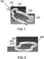
- FIG. 1 illustrates an overhead perspective view of a first micro electromechanical system or MEMS gyroscope 100, in accordance with one embodiment of the present invention.
- the first MEMS gyroscope 100 may be utilized as an angular rate sensor in biomedical implants and typically in vestibular implants where power consumption and reliability may be of concern.
- the first MEMS gyroscope 100 may also be utilized in a wearable electronic sensor or any other suitable application or usage.
- the first MEMS gyroscope 100 may be a hybrid MEMS microfluidic gyroscope 105 or other suitable MEMS gyroscope.
- the first MEMS gyroscope 100 may include a base enclosure 110 and a plurality of cantilevers 120.
- the base enclosure 110 may be bulk micro-machined or manufactured by any other suitable process.
- the base enclosure 110 may be made of silicon or any other suitable material.
- the base enclosure 110 may not necessarily be entirely made of the same material.
- the cantilevers 120 may serve as hair cells or other suitable type of sensory receptor. Angular rotation of the first MEMS gyroscope 100 may create an inertial force, which increases the pressure on the cantilevers 120, leading to a detectable deflection that is proportional to the angular rotation.
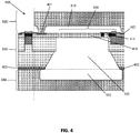
- FIG. 2 illustrates an overhead perspective view of a second MEMS gyroscope 200, in accordance with one embodiment of the present invention.
- the second MEMS gyroscope 200 may be utilized as an angular rate sensor in biomedical implants and typically in vestibular implants where power consumption and reliability may be of concern.
- the second MEMS gyroscope 200 may also be utilized in a wearable electronic sensor or any other suitable application or usage.
- the second MEMS gyroscope 200 may be a second hybrid MEMS microfluidic gyroscope 205 or other suitable type of gyroscope.
- the second MEMS gyroscope 200 may include a base enclosure 210 and a single membrane 220.
- the base enclosure 210 may be bulk micro-machined or manufactured by any other suitable process.
- the base enclosure 210 may be made of silicon or any other suitable material.
- the single membrane 220 may serve as a sensory receptor. Angular rotation of the second MEMS gyroscope 200 may create an inertial force, which increases the pressure on the single membrane 220, leading to a detectable deflection that is proportional to the angular rotation.
- FIG. 3 illustrates an exploded perspective view of a first MEMS gyroscope 300, in accordance with one embodiment of the present invention.
- the first MEMS gyroscope 300 may include a top fluid enclosure 310, a fluid sensing enclosure 320 and a bottom fluid enclosure 330.
- the top fluid enclosure 310 may be constructed by partially etching or otherwise machining glass or any other suitable material, thereby creating a pair of discrete canals 312 on a bottom side 311 of the top fluid enclosure 310.
- the fluid sensing enclosure 320 may be constructed from a layer of MEMS grade silicon or other suitable material which may be micro machined to include a sensing structure 324, which may be accessible to the fluid via an opening on either side of the fluid sensing enclosure 320.
- the bottom fluid enclosure 330 may be constructed by partially etching or otherwise machining glass or any other suitable material, thereby creating two discrete canals 332 on the top side 331 of bottom fluid enclosure 330.
- the top fluid enclosure 310, the fluid sensing enclosure 320 and the bottom fluid enclosure 330 may be hermetically bonded together utilizing an anodic bonding or other suitable technique, thereby forming a continuous fluid-filled closed shape that previously has been described as the base enclosure 110.
- FIG. 4 illustrates a cross-sectional view 400 of a first MEMS gyroscope along line 4-4 of FIG. 1 , in accordance with one embodiment of the present invention.
- the top fluid enclosure 310 and the fluid sensing enclosure 320 may be anodically bonded to a cantilever 410.
- the sensing structure 324 includes a cantilever 410 which may have a piezoresistor 411 embedded at the edge of the cantilever 410, where maximum stress and strain may occur.
- the pair of discrete canals 312 above the sensing structure 324 may be part of the top fluid enclosure 310.
- the fluid-filled void 322, below the sensing structure 324 communicates with the canal 332 on the top of bottom-fluid-enclosing structure 330.
- the fluidic mass that fills the entire base enclosure 110 may be any suitable high-density, low-viscosity and non-toxic fluid such as sodium polytungstate liquid or water that achieves an angular rate sensitivity similar to that of a healthly human.
- the fluidic mass in the first MEMS gyroscope may be free to flow in the pair of discrete canals 312 of the top fluid enclosing structure 310, through the openings of the fluid sensing structure 320, past the cantilever sensing structure and into and around the canals 332 of the bottom-fluid-enclosing structure 330.
- the piezo-resistors 411 may serve as piezoresistive strain gauges that may be strategically located at regions of maximum stress, which may be at the perimeter edges thereby giving maximum electrical sensitivity. The piezo-resistors 411 may be deformed by the movement of the fluidic mass.
- FIG. 3 illustrates four cantilever sensing structures 324 disposed within the fluid sensing structure 320 as this may be suitable for constructing a Wheatstone bridge however any suitable number of cantilevers 410 may be disposed within the sensing structure 320.
- FIG. 5 illustrates a cross-sectional view of a second MEMS gyroscope 500 along line 5-5 of FIG. 2 , in accordance with one embodiment of the present invention.
- the second MEMS gyroscope 500 may be utilized to detect fluid motion.
- the second MEMS gyroscope 500 may include a base enclosure 210, a top fluid enclosure 510, a fluid sensing enclosure 520 and a bottom fluid enclosure 530.
- the top fluid enclosure 510 may be constructed by partially etching or machining glass or any other suitable material, thereby creating a single top fluid canal 512 on a bottom side of the top fluid enclosure 510.
- the fluid sensing enclosure 520 may be constructed from a layer of MEMS grade silicon or other suitable material, which may be micro machined to include a circular sensing diaphragm 510', which is accessible to fluid on either side of the second MEMS gyroscope 500.
- the bottom fluid enclosure 530 may be constructed by partially etching or otherwise machining glass or other suitable material, thereby creating a canal 532 on a top side of the bottom fluid enclosure 530.
- the top fluid enclosure 510, the fluid sensing enclosure 520 and the bottom fluid enclosure 530 may be hermetically bonded together utilizing an anodic bonding or other suitable technique, thereby forming a continuous fluid filled closed shape with a circular sensing diaphragm 510' as outlined in FIG. 2 .
- the circular sensing diaphragm 510' has four piezoresistors 411 embedded at the edges, where it may be subjected to maximum stress and strain.
- the orientation may be such that under pressure, a pair of the piezoresistors 411 may exhibit compressive stress, while the other pair of the piezoresistors 411 may exhibit tensile stress, thereby enabling construction of a Wheatstone bridge. As illustrated in FIG. 5 , to maximize the sensitivity however any number of intercepting membranes may be built.
- FIG. 6 illustrates an electrical schematic of a Wheatstone bridge 600, in accordance with one embodiment of the present invention.
- the Wheatstone bridge 600 may include a plurality of piezo-resistors 610.
- the piezo-resistors 610 may be designed in pairs, either within different sensing structures as illustrated in the case of FIG. 3 , or within the same sensing structure as described in the case of a circular sensing diaphragm.
- a differential read-out circuit then may eliminate the effects of process variations.
- the piezo-resistors 610 may be placed longitudinally and two transversally to the stress axes, oriented parallel and perpendicular to the 110 crystallographic direction, in order to maximize the coefficients of piezo-resistivity. During angular motion, in each resistive divider leg, one piezo-resistor 610 may undergo compressive stress, while the other may undergo tensile stress.
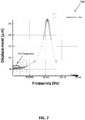
- FIG. 7 illustrates a graph 700 of a frequency response of a first hybrid MEMS microfluidic gyroscope, in accordance with one embodiment of the present invention.
- the graph 700 illustrates a flat response at the frequencies of interest, i.e. in the range of approximately 0 Hz to 1.5 Hz. Furthermore, the resonant frequencies of the cantilever structure are well beyond this range, being approximately 1.05 MHz and approximately 0.22 MHz respectively.
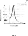
- FIG. 8 illustrates a graph 800 of a frequency response of a second hybrid MEMS microfluidic gyroscope, in accordance with one embodiment of the present invention.
- the graph 800 illustrates a flat response at the frequencies of interest, i.e. in the range of approximately 0 Hz to 1.5 Hz. Furthermore, the resonant frequencies of the cantilever structure are well beyond this range, being approximately 1.05 MHz and approximately 0.22 MHz respectively.
- the MEMS gyroscopes may be intended to be utilized as an angular rate sensor in biomedical implants and mostly in vestibular implants where power consumption and reliability are of major concern.
- the MEMS gyroscope may also be utilized in wearable electronic sensors. By choosing a high-density, low-viscosity and non-toxic fluid, a high angular-rate sensitivity may be achieved, that exceeds that of humans. Furthermore a thin enough sensing element may achieve high sensitivities.
- the MEMS gyroscopes may utilize a fluidic mass that may be contained in etched glass layers, which may be anodically bonded on top and below of a bulk micro-machined silicon layer, and whose deflectable structures contain buried piezo-resistors for sensing.
- the deflectable structures may include four cantilevers, one in each cross-section of the upper and lower levels of the channel, which may serve as the hair cells of the semi-circular canal or SCC.
- the deflectable structure may be a membrane. The membrane may increase the inertial mass and the sensitivity of the system without utilizing the Coriolis affect.
- Angular rotation of the whole device may create an inertial force, which may increase the pressure on the sensing membrane or the cantilever (hair cell), leading to a detectable deflection that is proportional to the angular rotation.
- the sensing piezoresistive strain gauges may be strategically located at regions of maximum stress a, which may be at the perimeter edges of the cantilever/membrane, to give increased electrical sensitivity.
- strain gauges may be designed in pairs, to form a Wheatstone bridge, which converts the strain induced resistance variations into output voltage variations.
- a differential read-out circuit then may eliminate the effects of process variations.
- two of the piezo-resistors are placed longitudinally and two transversally to the stress axes, oriented parallel and perpendicular to the 110 crystallographic direction, in order to maximize the coefficients of piezo-resistivity.
- each resistive divider leg one piezo-resistor undergoes compressive stress, while the other undergoes tensile stress. Thereby the two resistive divider legs may determine the output voltage.
- the two different structures, one with a sensing cantilever and another with a sensing membrane may be fabricated on two different dies in one of Sensonor's MEMS technologies.
Landscapes
- Physics & Mathematics (AREA)
- Health & Medical Sciences (AREA)
- General Physics & Mathematics (AREA)
- Life Sciences & Earth Sciences (AREA)
- Engineering & Computer Science (AREA)
- Biomedical Technology (AREA)
- Veterinary Medicine (AREA)
- Public Health (AREA)
- General Health & Medical Sciences (AREA)
- Animal Behavior & Ethology (AREA)
- Biophysics (AREA)
- Medical Informatics (AREA)
- Molecular Biology (AREA)
- Surgery (AREA)
- Pathology (AREA)
- Heart & Thoracic Surgery (AREA)
- Physiology (AREA)
- Remote Sensing (AREA)
- Radar, Positioning & Navigation (AREA)
- Dentistry (AREA)
- Neurology (AREA)
- Neurosurgery (AREA)
- Geometry (AREA)
- Oral & Maxillofacial Surgery (AREA)
- Micromachines (AREA)
- Otolaryngology (AREA)
- Nuclear Medicine, Radiotherapy & Molecular Imaging (AREA)
- Radiology & Medical Imaging (AREA)
Claims (7)
- Vestibulares Implantat, aufweisend ein hybrides MEMS-Mikrofluidgyroskop, aufweisend:- eine mikrobearbeitete Basisumfassung mit einer oberen Fluidumfassung, einer Fluiderfassungsumfassung und einer unteren Fluidumfassung, wobei die obere Fluidumfassung teilweise durch Ätzen oder maschinelles Bearbeiten von Glas hergestellt ist, um dadurch ein paar von diskreten Kanälen auf der Unterseite der oberen Fluidumfassung zu erzeugen, wobei die Fluiderfassungsumfassung mikrobearbeitet ist, um eine Erfassungsstruktur aufzuweisen, die für ein Fluid über eine Öffnung an jeder Seite der Fluiderfassungsumfassung zugänglich ist und wobei die untere Fluidumfassung durch teilweises Ätzen oder maschinelles Bearbeiten von Glas hergestellt ist, wodurch zwei diskrete Kanäle auf der Oberseite der unteren Fluidumfassung erzeugt werden;- eine Mehrzahl von Piezowiderständen, die innerhalb der mikrobearbeiteten Basisumfassung angeordnet sind, wobei die Piezowiderstände durch das Fluid deformiert werden, wobei das Fluid vermeidet, dass Gravitationskräfte, die auf das hybride MEMS-Mikrofluidgyroskop wirken, die Piezowiderstände beeinträchtigen; und- eine Mehrzahl von Ausleger, die innerhalb der mikrobearbeiteten Basisumfassung angeordnet sind, wobei die Ausleger als eine Mehrzahl von Haarzellen fungieren, wobei eine Winkeldrehung des hybriden MEMS-Mikrofluidgyroskop eine Trägheitskraft erzeugt, die den Druck auf die Ausleger erhöht, was zu einer erfassbaren Verbiegung führt, die proportional zur Winkeldrehung ist.
- Vestibulares Implantat nach Anspruch 1, wobei die Fluiderfassungsumhüllung aus einer Lage von MEMS-Grad-Silizium hergestellt ist.
- Vestibulares Implantat nach Anspruch 1, wobei die Fluiderfassungsumfassung anodisch mit anderen Fluidumfassungsstrukturen gebondet ist.
- Vestibulares Implantat nach Anspruch 1, wobei die fluide Masse ein Fluid mit einer hohen Dichte, einer niedrigen Viskosität und keiner Toxizität ist.
- Vestibulares Implantat nach Anspruch 4, wobei das hochdichte, niedrigviskose und nicht toxische Fluid eine Natriumpolywolframad-Flüssigkeit ist.
- Vestibulares Implantat nach Anspruch 4, wobei das hochdichte, niederviskose und nicht toxische Fluid Wasser oder ohne einem löslichen Material ist.
- Vestibulares Implantat nach Anspruch 1, wobei die Piezowiderstände als piezoresistive Dehnungsmessstreifen fungieren, die an den Umfangskanten der Ausleger angeordnet sind.
Applications Claiming Priority (2)
| Application Number | Priority Date | Filing Date | Title |
|---|---|---|---|
| US201261696318P | 2012-09-04 | 2012-09-04 | |
| PCT/IB2013/002555 WO2014037808A1 (en) | 2012-09-04 | 2013-09-04 | Hybrid mems microfluidic gyroscope |
Publications (2)
| Publication Number | Publication Date |
|---|---|
| EP2893296A1 EP2893296A1 (de) | 2015-07-15 |
| EP2893296B1 true EP2893296B1 (de) | 2018-08-29 |
Family
ID=49880840
Family Applications (1)
| Application Number | Title | Priority Date | Filing Date |
|---|---|---|---|
| EP13812069.6A Not-in-force EP2893296B1 (de) | 2012-09-04 | 2013-09-04 | Vestibuläres implantat mit einem hybriden mems mikrofluidischen gyroskop |
Country Status (3)
| Country | Link |
|---|---|
| US (2) | US9759562B2 (de) |
| EP (1) | EP2893296B1 (de) |
| WO (1) | WO2014037808A1 (de) |
Families Citing this family (3)
| Publication number | Priority date | Publication date | Assignee | Title |
|---|---|---|---|---|
| JP6548067B2 (ja) * | 2014-05-02 | 2019-07-24 | 国立大学法人 東京大学 | ジャイロセンサ |
| JP7152752B2 (ja) | 2018-09-14 | 2022-10-13 | 国立大学法人 東京大学 | 角加速度センサ |
| CN112683255A (zh) * | 2020-12-28 | 2021-04-20 | 贵州航天计量测试技术研究所 | 一种基于阿基米德螺线微通道无阀压电泵的mems流体陀螺 |
Family Cites Families (7)
| Publication number | Priority date | Publication date | Assignee | Title |
|---|---|---|---|---|
| BE789248A (fr) * | 1969-09-22 | 1973-03-26 | Texaco Development Corp | Accelerometre. |
| EP0566130A1 (de) * | 1992-04-17 | 1993-10-20 | Hughes Aircraft Company | Drehmessfühler |
| US20030047002A1 (en) * | 1998-10-28 | 2003-03-13 | Steven W. Arms | Mems based angular accelerometer |
| TWI325958B (en) * | 2007-04-26 | 2010-06-11 | Ind Tech Res Inst | Inertial sensor and producing method thereof |
| CN102530831B (zh) * | 2010-12-27 | 2014-05-21 | 上海丽恒光微电子科技有限公司 | Mems器件的制作方法 |
| US8864287B2 (en) * | 2011-04-19 | 2014-10-21 | Eastman Kodak Company | Fluid ejection using MEMS composite transducer |
| US8759990B2 (en) * | 2011-04-19 | 2014-06-24 | Eastman Kodak Company | Energy harvesting device including MEMS composite transducer |
-
2013
- 2013-09-04 EP EP13812069.6A patent/EP2893296B1/de not_active Not-in-force
- 2013-09-04 WO PCT/IB2013/002555 patent/WO2014037808A1/en not_active Ceased
- 2013-09-04 US US14/425,153 patent/US9759562B2/en not_active Expired - Fee Related
-
2017
- 2017-08-28 US US15/688,052 patent/US10563982B2/en not_active Expired - Fee Related
Also Published As
| Publication number | Publication date |
|---|---|
| US10563982B2 (en) | 2020-02-18 |
| EP2893296A1 (de) | 2015-07-15 |
| WO2014037808A1 (en) | 2014-03-13 |
| US9759562B2 (en) | 2017-09-12 |
| US20180045514A1 (en) | 2018-02-15 |
| US20150260518A1 (en) | 2015-09-17 |
Similar Documents
| Publication | Publication Date | Title |
|---|---|---|
| EP1738181B1 (de) | Elektrodenaufhängung zur kompensation der auslenkung aus der substratebene für einen beschleunigungsmesser | |
| EP2643702B1 (de) | Resonante biaxiale beschleunigungsmesserstrutkur der mikroelektromechanischen art | |
| US20040182155A1 (en) | Micromachined capacitive lateral accelerometer device and monolithic, three-axis accelerometer having same | |
| CN102157679A (zh) | 用于制造传感器的方法 | |
| EP1914512A3 (de) | Kraftneuausgleich und Parametererweiterung für träge MEMS-Sensoren | |
| Aktakka et al. | A microactuation and sensing platform with active lockdown for in situ calibration of scale factor drifts in dual-axis gyroscopes | |
| US10563982B2 (en) | Hybrid MEMS microfluidic gyroscope | |
| Zhe et al. | A microfabricated wall shear-stress sensor with capacitative sensing | |
| Li et al. | Micromachined piezoresistive accelerometers based on an asymmetrically gapped cantilever | |
| Kim et al. | A skew-symmetric cantilever accelerometer for automotive airbag applications | |
| CN103649716A (zh) | 分析装置 | |
| Chen et al. | Unpowered spiral-tube parylene pressure sensor for intraocular pressure sensing | |
| EP2703824A1 (de) | MEMS-Beschleunigungsmessvorrichtung mit in der Substratebene verschwenkbaren Pendelmassen | |
| Messina et al. | Design and simulation of a novel biomechanic piezoresistive sensor with silicon nanowires | |
| Ravi Sankar et al. | Performance enhancement of a silicon MEMS piezoresistive single axis accelerometer with electroplated gold on a proof mass | |
| Zhang et al. | Conception, fabrication and characterization of a silicon based MEMS inertial switch with a threshold value of 5 g | |
| US20030047002A1 (en) | Mems based angular accelerometer | |
| US20070028683A1 (en) | Apparatus and method for sensing pressure utilizing a deformable cavity | |
| Andreou et al. | Bio-mimetic gyroscopic sensor for vestibular prostheses | |
| US20230305036A1 (en) | Accelerometer element for detecting out-of-plane accelerations | |
| Dheringe et al. | Recent advances in mems sensor technology biomedical mechanical thermo-fluid & electromagnetic sensors | |
| Sindhanaiselvi et al. | Performance analysis of embossed diaphragm based MEMS piezo resistive pressure sensor for flood level measurement | |
| Zhu et al. | A MEMS hybrid inertial sensor based on convection heat transfer | |
| Zhang et al. | Analytical and experimental study on sensitivity of planar piezoresistive vibration sensor | |
| Dao et al. | Development of a 3-DOF silicon piezoresistive micro accelerometer |
Legal Events
| Date | Code | Title | Description |
|---|---|---|---|
| PUAI | Public reference made under article 153(3) epc to a published international application that has entered the european phase |
Free format text: ORIGINAL CODE: 0009012 |
|
| 17P | Request for examination filed |
Effective date: 20150402 |
|
| AK | Designated contracting states |
Kind code of ref document: A1 Designated state(s): AL AT BE BG CH CY CZ DE DK EE ES FI FR GB GR HR HU IE IS IT LI LT LU LV MC MK MT NL NO PL PT RO RS SE SI SK SM TR |
|
| AX | Request for extension of the european patent |
Extension state: BA ME |
|
| DAX | Request for extension of the european patent (deleted) | ||
| 17Q | First examination report despatched |
Effective date: 20170316 |
|
| GRAP | Despatch of communication of intention to grant a patent |
Free format text: ORIGINAL CODE: EPIDOSNIGR1 |
|
| INTG | Intention to grant announced |
Effective date: 20180307 |
|
| GRAS | Grant fee paid |
Free format text: ORIGINAL CODE: EPIDOSNIGR3 |
|
| GRAA | (expected) grant |
Free format text: ORIGINAL CODE: 0009210 |
|
| AK | Designated contracting states |
Kind code of ref document: B1 Designated state(s): AL AT BE BG CH CY CZ DE DK EE ES FI FR GB GR HR HU IE IS IT LI LT LU LV MC MK MT NL NO PL PT RO RS SE SI SK SM TR |
|
| REG | Reference to a national code |
Ref country code: GB Ref legal event code: FG4D |
|
| REG | Reference to a national code |
Ref country code: CH Ref legal event code: EP |
|
| REG | Reference to a national code |
Ref country code: AT Ref legal event code: REF Ref document number: 1035639 Country of ref document: AT Kind code of ref document: T Effective date: 20180915 |
|
| REG | Reference to a national code |
Ref country code: IE Ref legal event code: FG4D |
|
| REG | Reference to a national code |
Ref country code: DE Ref legal event code: R096 Ref document number: 602013042858 Country of ref document: DE |
|
| REG | Reference to a national code |
Ref country code: CH Ref legal event code: PK Free format text: BERICHTIGUNGEN |
|
| RAP2 | Party data changed (patent owner data changed or rights of a patent transferred) |
Owner name: UNIVERSITY OF CYPRUS |
|
| RIN2 | Information on inventor provided after grant (corrected) |
Inventor name: GEORGIOU, JULIUS Inventor name: ANDREOU, CHARALAMBOS, MICHAEL |
|
| REG | Reference to a national code |
Ref country code: NL Ref legal event code: MP Effective date: 20180829 |
|
| REG | Reference to a national code |
Ref country code: LT Ref legal event code: MG4D |
|
| PG25 | Lapsed in a contracting state [announced via postgrant information from national office to epo] |
Ref country code: GR Free format text: LAPSE BECAUSE OF FAILURE TO SUBMIT A TRANSLATION OF THE DESCRIPTION OR TO PAY THE FEE WITHIN THE PRESCRIBED TIME-LIMIT Effective date: 20181130 Ref country code: FI Free format text: LAPSE BECAUSE OF FAILURE TO SUBMIT A TRANSLATION OF THE DESCRIPTION OR TO PAY THE FEE WITHIN THE PRESCRIBED TIME-LIMIT Effective date: 20180829 Ref country code: LT Free format text: LAPSE BECAUSE OF FAILURE TO SUBMIT A TRANSLATION OF THE DESCRIPTION OR TO PAY THE FEE WITHIN THE PRESCRIBED TIME-LIMIT Effective date: 20180829 Ref country code: NO Free format text: LAPSE BECAUSE OF FAILURE TO SUBMIT A TRANSLATION OF THE DESCRIPTION OR TO PAY THE FEE WITHIN THE PRESCRIBED TIME-LIMIT Effective date: 20181129 Ref country code: SE Free format text: LAPSE BECAUSE OF FAILURE TO SUBMIT A TRANSLATION OF THE DESCRIPTION OR TO PAY THE FEE WITHIN THE PRESCRIBED TIME-LIMIT Effective date: 20180829 Ref country code: BG Free format text: LAPSE BECAUSE OF FAILURE TO SUBMIT A TRANSLATION OF THE DESCRIPTION OR TO PAY THE FEE WITHIN THE PRESCRIBED TIME-LIMIT Effective date: 20181129 Ref country code: NL Free format text: LAPSE BECAUSE OF FAILURE TO SUBMIT A TRANSLATION OF THE DESCRIPTION OR TO PAY THE FEE WITHIN THE PRESCRIBED TIME-LIMIT Effective date: 20180829 Ref country code: RS Free format text: LAPSE BECAUSE OF FAILURE TO SUBMIT A TRANSLATION OF THE DESCRIPTION OR TO PAY THE FEE WITHIN THE PRESCRIBED TIME-LIMIT Effective date: 20180829 Ref country code: IS Free format text: LAPSE BECAUSE OF FAILURE TO SUBMIT A TRANSLATION OF THE DESCRIPTION OR TO PAY THE FEE WITHIN THE PRESCRIBED TIME-LIMIT Effective date: 20181229 |
|
| REG | Reference to a national code |
Ref country code: AT Ref legal event code: MK05 Ref document number: 1035639 Country of ref document: AT Kind code of ref document: T Effective date: 20180829 |
|
| PG25 | Lapsed in a contracting state [announced via postgrant information from national office to epo] |
Ref country code: HR Free format text: LAPSE BECAUSE OF FAILURE TO SUBMIT A TRANSLATION OF THE DESCRIPTION OR TO PAY THE FEE WITHIN THE PRESCRIBED TIME-LIMIT Effective date: 20180829 Ref country code: AL Free format text: LAPSE BECAUSE OF FAILURE TO SUBMIT A TRANSLATION OF THE DESCRIPTION OR TO PAY THE FEE WITHIN THE PRESCRIBED TIME-LIMIT Effective date: 20180829 Ref country code: LV Free format text: LAPSE BECAUSE OF FAILURE TO SUBMIT A TRANSLATION OF THE DESCRIPTION OR TO PAY THE FEE WITHIN THE PRESCRIBED TIME-LIMIT Effective date: 20180829 |
|
| PG25 | Lapsed in a contracting state [announced via postgrant information from national office to epo] |
Ref country code: ES Free format text: LAPSE BECAUSE OF FAILURE TO SUBMIT A TRANSLATION OF THE DESCRIPTION OR TO PAY THE FEE WITHIN THE PRESCRIBED TIME-LIMIT Effective date: 20180829 Ref country code: AT Free format text: LAPSE BECAUSE OF FAILURE TO SUBMIT A TRANSLATION OF THE DESCRIPTION OR TO PAY THE FEE WITHIN THE PRESCRIBED TIME-LIMIT Effective date: 20180829 Ref country code: CZ Free format text: LAPSE BECAUSE OF FAILURE TO SUBMIT A TRANSLATION OF THE DESCRIPTION OR TO PAY THE FEE WITHIN THE PRESCRIBED TIME-LIMIT Effective date: 20180829 Ref country code: IT Free format text: LAPSE BECAUSE OF FAILURE TO SUBMIT A TRANSLATION OF THE DESCRIPTION OR TO PAY THE FEE WITHIN THE PRESCRIBED TIME-LIMIT Effective date: 20180829 Ref country code: RO Free format text: LAPSE BECAUSE OF FAILURE TO SUBMIT A TRANSLATION OF THE DESCRIPTION OR TO PAY THE FEE WITHIN THE PRESCRIBED TIME-LIMIT Effective date: 20180829 Ref country code: EE Free format text: LAPSE BECAUSE OF FAILURE TO SUBMIT A TRANSLATION OF THE DESCRIPTION OR TO PAY THE FEE WITHIN THE PRESCRIBED TIME-LIMIT Effective date: 20180829 Ref country code: PL Free format text: LAPSE BECAUSE OF FAILURE TO SUBMIT A TRANSLATION OF THE DESCRIPTION OR TO PAY THE FEE WITHIN THE PRESCRIBED TIME-LIMIT Effective date: 20180829 |
|
| REG | Reference to a national code |
Ref country code: CH Ref legal event code: PL |
|
| PG25 | Lapsed in a contracting state [announced via postgrant information from national office to epo] |
Ref country code: DK Free format text: LAPSE BECAUSE OF FAILURE TO SUBMIT A TRANSLATION OF THE DESCRIPTION OR TO PAY THE FEE WITHIN THE PRESCRIBED TIME-LIMIT Effective date: 20180829 Ref country code: SK Free format text: LAPSE BECAUSE OF FAILURE TO SUBMIT A TRANSLATION OF THE DESCRIPTION OR TO PAY THE FEE WITHIN THE PRESCRIBED TIME-LIMIT Effective date: 20180829 Ref country code: SM Free format text: LAPSE BECAUSE OF FAILURE TO SUBMIT A TRANSLATION OF THE DESCRIPTION OR TO PAY THE FEE WITHIN THE PRESCRIBED TIME-LIMIT Effective date: 20180829 |
|
| REG | Reference to a national code |
Ref country code: DE Ref legal event code: R097 Ref document number: 602013042858 Country of ref document: DE |
|
| REG | Reference to a national code |
Ref country code: BE Ref legal event code: MM Effective date: 20180930 |
|
| REG | Reference to a national code |
Ref country code: IE Ref legal event code: MM4A |
|
| PG25 | Lapsed in a contracting state [announced via postgrant information from national office to epo] |
Ref country code: MC Free format text: LAPSE BECAUSE OF FAILURE TO SUBMIT A TRANSLATION OF THE DESCRIPTION OR TO PAY THE FEE WITHIN THE PRESCRIBED TIME-LIMIT Effective date: 20180829 Ref country code: LU Free format text: LAPSE BECAUSE OF NON-PAYMENT OF DUE FEES Effective date: 20180904 |
|
| PLBE | No opposition filed within time limit |
Free format text: ORIGINAL CODE: 0009261 |
|
| STAA | Information on the status of an ep patent application or granted ep patent |
Free format text: STATUS: NO OPPOSITION FILED WITHIN TIME LIMIT |
|
| PG25 | Lapsed in a contracting state [announced via postgrant information from national office to epo] |
Ref country code: IE Free format text: LAPSE BECAUSE OF NON-PAYMENT OF DUE FEES Effective date: 20180904 |
|
| 26N | No opposition filed |
Effective date: 20190531 |
|
| PG25 | Lapsed in a contracting state [announced via postgrant information from national office to epo] |
Ref country code: LI Free format text: LAPSE BECAUSE OF NON-PAYMENT OF DUE FEES Effective date: 20180930 Ref country code: SI Free format text: LAPSE BECAUSE OF FAILURE TO SUBMIT A TRANSLATION OF THE DESCRIPTION OR TO PAY THE FEE WITHIN THE PRESCRIBED TIME-LIMIT Effective date: 20180829 Ref country code: CH Free format text: LAPSE BECAUSE OF NON-PAYMENT OF DUE FEES Effective date: 20180930 Ref country code: BE Free format text: LAPSE BECAUSE OF NON-PAYMENT OF DUE FEES Effective date: 20180930 |
|
| PG25 | Lapsed in a contracting state [announced via postgrant information from national office to epo] |
Ref country code: MT Free format text: LAPSE BECAUSE OF NON-PAYMENT OF DUE FEES Effective date: 20180904 |
|
| PG25 | Lapsed in a contracting state [announced via postgrant information from national office to epo] |
Ref country code: TR Free format text: LAPSE BECAUSE OF FAILURE TO SUBMIT A TRANSLATION OF THE DESCRIPTION OR TO PAY THE FEE WITHIN THE PRESCRIBED TIME-LIMIT Effective date: 20180829 |
|
| PG25 | Lapsed in a contracting state [announced via postgrant information from national office to epo] |
Ref country code: PT Free format text: LAPSE BECAUSE OF FAILURE TO SUBMIT A TRANSLATION OF THE DESCRIPTION OR TO PAY THE FEE WITHIN THE PRESCRIBED TIME-LIMIT Effective date: 20180829 |
|
| PG25 | Lapsed in a contracting state [announced via postgrant information from national office to epo] |
Ref country code: MK Free format text: LAPSE BECAUSE OF NON-PAYMENT OF DUE FEES Effective date: 20180829 Ref country code: HU Free format text: LAPSE BECAUSE OF FAILURE TO SUBMIT A TRANSLATION OF THE DESCRIPTION OR TO PAY THE FEE WITHIN THE PRESCRIBED TIME-LIMIT; INVALID AB INITIO Effective date: 20130904 Ref country code: CY Free format text: LAPSE BECAUSE OF FAILURE TO SUBMIT A TRANSLATION OF THE DESCRIPTION OR TO PAY THE FEE WITHIN THE PRESCRIBED TIME-LIMIT Effective date: 20180829 |
|
| PGFP | Annual fee paid to national office [announced via postgrant information from national office to epo] |
Ref country code: GB Payment date: 20220328 Year of fee payment: 9 Ref country code: DE Payment date: 20220328 Year of fee payment: 9 |
|
| PGFP | Annual fee paid to national office [announced via postgrant information from national office to epo] |
Ref country code: FR Payment date: 20220328 Year of fee payment: 9 |
|
| REG | Reference to a national code |
Ref country code: DE Ref legal event code: R119 Ref document number: 602013042858 Country of ref document: DE |
|
| GBPC | Gb: european patent ceased through non-payment of renewal fee |
Effective date: 20220904 |
|
| PG25 | Lapsed in a contracting state [announced via postgrant information from national office to epo] |
Ref country code: FR Free format text: LAPSE BECAUSE OF NON-PAYMENT OF DUE FEES Effective date: 20220930 Ref country code: DE Free format text: LAPSE BECAUSE OF NON-PAYMENT OF DUE FEES Effective date: 20230401 |
|
| PG25 | Lapsed in a contracting state [announced via postgrant information from national office to epo] |
Ref country code: GB Free format text: LAPSE BECAUSE OF NON-PAYMENT OF DUE FEES Effective date: 20220904 |