EP2893121B1 - Modified tubular - Google Patents
Modified tubular Download PDFInfo
- Publication number
- EP2893121B1 EP2893121B1 EP13722299.8A EP13722299A EP2893121B1 EP 2893121 B1 EP2893121 B1 EP 2893121B1 EP 13722299 A EP13722299 A EP 13722299A EP 2893121 B1 EP2893121 B1 EP 2893121B1
- Authority
- EP
- European Patent Office
- Prior art keywords
- tubular
- particulates
- prefabricated composite
- composite shell
- shell
- Prior art date
- Legal status (The legal status is an assumption and is not a legal conclusion. Google has not performed a legal analysis and makes no representation as to the accuracy of the status listed.)
- Active
Links
Images

Classifications
-
- E—FIXED CONSTRUCTIONS
- E21—EARTH DRILLING; MINING
- E21B—EARTH DRILLING, e.g. DEEP DRILLING; OBTAINING OIL, GAS, WATER, SOLUBLE OR MELTABLE MATERIALS OR A SLURRY OF MINERALS FROM WELLS
- E21B17/00—Drilling rods or pipes; Flexible drill strings; Kellies; Drill collars; Sucker rods; Cables; Casings; Tubings
- E21B17/10—Wear protectors; Centralising devices, e.g. stabilisers
- E21B17/1042—Elastomer protector or centering means
-
- B—PERFORMING OPERATIONS; TRANSPORTING
- B29—WORKING OF PLASTICS; WORKING OF SUBSTANCES IN A PLASTIC STATE IN GENERAL
- B29C—SHAPING OR JOINING OF PLASTICS; SHAPING OF MATERIAL IN A PLASTIC STATE, NOT OTHERWISE PROVIDED FOR; AFTER-TREATMENT OF THE SHAPED PRODUCTS, e.g. REPAIRING
- B29C45/00—Injection moulding, i.e. forcing the required volume of moulding material through a nozzle into a closed mould; Apparatus therefor
- B29C45/14—Injection moulding, i.e. forcing the required volume of moulding material through a nozzle into a closed mould; Apparatus therefor incorporating preformed parts or layers, e.g. injection moulding around inserts or for coating articles
- B29C45/14778—Injection moulding, i.e. forcing the required volume of moulding material through a nozzle into a closed mould; Apparatus therefor incorporating preformed parts or layers, e.g. injection moulding around inserts or for coating articles the article consisting of a material with particular properties, e.g. porous, brittle
- B29C45/14786—Fibrous material or fibre containing material, e.g. fibre mats or fibre reinforced material
-
- B—PERFORMING OPERATIONS; TRANSPORTING
- B29—WORKING OF PLASTICS; WORKING OF SUBSTANCES IN A PLASTIC STATE IN GENERAL
- B29C—SHAPING OR JOINING OF PLASTICS; SHAPING OF MATERIAL IN A PLASTIC STATE, NOT OTHERWISE PROVIDED FOR; AFTER-TREATMENT OF THE SHAPED PRODUCTS, e.g. REPAIRING
- B29C45/00—Injection moulding, i.e. forcing the required volume of moulding material through a nozzle into a closed mould; Apparatus therefor
- B29C45/16—Making multilayered or multicoloured articles
- B29C45/1671—Making multilayered or multicoloured articles with an insert
-
- B—PERFORMING OPERATIONS; TRANSPORTING
- B29—WORKING OF PLASTICS; WORKING OF SUBSTANCES IN A PLASTIC STATE IN GENERAL
- B29C—SHAPING OR JOINING OF PLASTICS; SHAPING OF MATERIAL IN A PLASTIC STATE, NOT OTHERWISE PROVIDED FOR; AFTER-TREATMENT OF THE SHAPED PRODUCTS, e.g. REPAIRING
- B29C70/00—Shaping composites, i.e. plastics material comprising reinforcements, fillers or preformed parts, e.g. inserts
- B29C70/02—Shaping composites, i.e. plastics material comprising reinforcements, fillers or preformed parts, e.g. inserts comprising combinations of reinforcements, e.g. non-specified reinforcements, fibrous reinforcing inserts and fillers, e.g. particulate fillers, incorporated in matrix material, forming one or more layers and with or without non-reinforced or non-filled layers
- B29C70/021—Combinations of fibrous reinforcement and non-fibrous material
- B29C70/023—Combinations of fibrous reinforcement and non-fibrous material with reinforcing inserts
-
- B—PERFORMING OPERATIONS; TRANSPORTING
- B29—WORKING OF PLASTICS; WORKING OF SUBSTANCES IN A PLASTIC STATE IN GENERAL
- B29C—SHAPING OR JOINING OF PLASTICS; SHAPING OF MATERIAL IN A PLASTIC STATE, NOT OTHERWISE PROVIDED FOR; AFTER-TREATMENT OF THE SHAPED PRODUCTS, e.g. REPAIRING
- B29C70/00—Shaping composites, i.e. plastics material comprising reinforcements, fillers or preformed parts, e.g. inserts
- B29C70/04—Shaping composites, i.e. plastics material comprising reinforcements, fillers or preformed parts, e.g. inserts comprising reinforcements only, e.g. self-reinforcing plastics
- B29C70/06—Fibrous reinforcements only
-
- B—PERFORMING OPERATIONS; TRANSPORTING
- B29—WORKING OF PLASTICS; WORKING OF SUBSTANCES IN A PLASTIC STATE IN GENERAL
- B29C—SHAPING OR JOINING OF PLASTICS; SHAPING OF MATERIAL IN A PLASTIC STATE, NOT OTHERWISE PROVIDED FOR; AFTER-TREATMENT OF THE SHAPED PRODUCTS, e.g. REPAIRING
- B29C70/00—Shaping composites, i.e. plastics material comprising reinforcements, fillers or preformed parts, e.g. inserts
- B29C70/68—Shaping composites, i.e. plastics material comprising reinforcements, fillers or preformed parts, e.g. inserts by incorporating or moulding on preformed parts, e.g. inserts or layers, e.g. foam blocks
-
- B—PERFORMING OPERATIONS; TRANSPORTING
- B32—LAYERED PRODUCTS
- B32B—LAYERED PRODUCTS, i.e. PRODUCTS BUILT-UP OF STRATA OF FLAT OR NON-FLAT, e.g. CELLULAR OR HONEYCOMB, FORM
- B32B37/00—Methods or apparatus for laminating, e.g. by curing or by ultrasonic bonding
- B32B37/12—Methods or apparatus for laminating, e.g. by curing or by ultrasonic bonding characterised by using adhesives
- B32B37/1284—Application of adhesive
-
- B—PERFORMING OPERATIONS; TRANSPORTING
- B32—LAYERED PRODUCTS
- B32B—LAYERED PRODUCTS, i.e. PRODUCTS BUILT-UP OF STRATA OF FLAT OR NON-FLAT, e.g. CELLULAR OR HONEYCOMB, FORM
- B32B37/00—Methods or apparatus for laminating, e.g. by curing or by ultrasonic bonding
- B32B37/14—Methods or apparatus for laminating, e.g. by curing or by ultrasonic bonding characterised by the properties of the layers
- B32B37/16—Methods or apparatus for laminating, e.g. by curing or by ultrasonic bonding characterised by the properties of the layers with all layers existing as coherent layers before laminating
-
- E—FIXED CONSTRUCTIONS
- E21—EARTH DRILLING; MINING
- E21B—EARTH DRILLING, e.g. DEEP DRILLING; OBTAINING OIL, GAS, WATER, SOLUBLE OR MELTABLE MATERIALS OR A SLURRY OF MINERALS FROM WELLS
- E21B17/00—Drilling rods or pipes; Flexible drill strings; Kellies; Drill collars; Sucker rods; Cables; Casings; Tubings
- E21B17/10—Wear protectors; Centralising devices, e.g. stabilisers
- E21B17/1078—Stabilisers or centralisers for casing, tubing or drill pipes
-
- E—FIXED CONSTRUCTIONS
- E21—EARTH DRILLING; MINING
- E21B—EARTH DRILLING, e.g. DEEP DRILLING; OBTAINING OIL, GAS, WATER, SOLUBLE OR MELTABLE MATERIALS OR A SLURRY OF MINERALS FROM WELLS
- E21B17/00—Drilling rods or pipes; Flexible drill strings; Kellies; Drill collars; Sucker rods; Cables; Casings; Tubings
- E21B17/10—Wear protectors; Centralising devices, e.g. stabilisers
- E21B17/1085—Wear protectors; Blast joints; Hard facing
-
- B—PERFORMING OPERATIONS; TRANSPORTING
- B29—WORKING OF PLASTICS; WORKING OF SUBSTANCES IN A PLASTIC STATE IN GENERAL
- B29K—INDEXING SCHEME ASSOCIATED WITH SUBCLASSES B29B, B29C OR B29D, RELATING TO MOULDING MATERIALS OR TO MATERIALS FOR MOULDS, REINFORCEMENTS, FILLERS OR PREFORMED PARTS, e.g. INSERTS
- B29K2105/00—Condition, form or state of moulded material or of the material to be shaped
- B29K2105/06—Condition, form or state of moulded material or of the material to be shaped containing reinforcements, fillers or inserts
- B29K2105/08—Condition, form or state of moulded material or of the material to be shaped containing reinforcements, fillers or inserts of continuous length, e.g. cords, rovings, mats, fabrics, strands or yarns
- B29K2105/0854—Condition, form or state of moulded material or of the material to be shaped containing reinforcements, fillers or inserts of continuous length, e.g. cords, rovings, mats, fabrics, strands or yarns in the form of a non-woven mat
-
- B—PERFORMING OPERATIONS; TRANSPORTING
- B29—WORKING OF PLASTICS; WORKING OF SUBSTANCES IN A PLASTIC STATE IN GENERAL
- B29K—INDEXING SCHEME ASSOCIATED WITH SUBCLASSES B29B, B29C OR B29D, RELATING TO MOULDING MATERIALS OR TO MATERIALS FOR MOULDS, REINFORCEMENTS, FILLERS OR PREFORMED PARTS, e.g. INSERTS
- B29K2509/00—Use of inorganic materials not provided for in groups B29K2503/00 - B29K2507/00, as filler
- B29K2509/02—Ceramics
- B29K2509/04—Carbides; Nitrides
-
- B—PERFORMING OPERATIONS; TRANSPORTING
- B29—WORKING OF PLASTICS; WORKING OF SUBSTANCES IN A PLASTIC STATE IN GENERAL
- B29L—INDEXING SCHEME ASSOCIATED WITH SUBCLASS B29C, RELATING TO PARTICULAR ARTICLES
- B29L2009/00—Layered products
-
- B—PERFORMING OPERATIONS; TRANSPORTING
- B29—WORKING OF PLASTICS; WORKING OF SUBSTANCES IN A PLASTIC STATE IN GENERAL
- B29L—INDEXING SCHEME ASSOCIATED WITH SUBCLASS B29C, RELATING TO PARTICULAR ARTICLES
- B29L2023/00—Tubular articles
- B29L2023/22—Tubes or pipes, i.e. rigid
-
- B—PERFORMING OPERATIONS; TRANSPORTING
- B32—LAYERED PRODUCTS
- B32B—LAYERED PRODUCTS, i.e. PRODUCTS BUILT-UP OF STRATA OF FLAT OR NON-FLAT, e.g. CELLULAR OR HONEYCOMB, FORM
- B32B2305/00—Condition, form or state of the layers or laminate
- B32B2305/08—Reinforcements
-
- B—PERFORMING OPERATIONS; TRANSPORTING
- B32—LAYERED PRODUCTS
- B32B—LAYERED PRODUCTS, i.e. PRODUCTS BUILT-UP OF STRATA OF FLAT OR NON-FLAT, e.g. CELLULAR OR HONEYCOMB, FORM
- B32B2597/00—Tubular articles, e.g. hoses, pipes
-
- Y—GENERAL TAGGING OF NEW TECHNOLOGICAL DEVELOPMENTS; GENERAL TAGGING OF CROSS-SECTIONAL TECHNOLOGIES SPANNING OVER SEVERAL SECTIONS OF THE IPC; TECHNICAL SUBJECTS COVERED BY FORMER USPC CROSS-REFERENCE ART COLLECTIONS [XRACs] AND DIGESTS
- Y10—TECHNICAL SUBJECTS COVERED BY FORMER USPC
- Y10T—TECHNICAL SUBJECTS COVERED BY FORMER US CLASSIFICATION
- Y10T156/00—Adhesive bonding and miscellaneous chemical manufacture
- Y10T156/10—Methods of surface bonding and/or assembly therefor
Definitions
- Oil and gas reservoirs may be exploited by tapping the resources therein via wellbores. Drilling of wellbores may require drilling a considerable distance into the earth. Many oil & gas bearing formations are at sub-sea locations. The direction of drilling may vary from a vertical position to a horizontal position.
- the wellbore created by drilling may be stabilised by use of casing or lining or by other measures.
- Tubular bodies (hereinafter “tubulars”) may be positioned in the wellbore. The tubular bodies may be cemented into position. The positioning of tubulars in the wellbore may be complicated by variations in wellbore direction. Tubulars may have mechanical components mounted thereon for the purposes of improving alignment and stable positioning of the tubulars in the wellbore. Correct positioning of the tubulars permits cementing to a satisfactory standard.
- US4146060 discloses a drill pipe wear belt assembly.
- a steel wear belt having a prepared inner surface with an inner diameter large enough to pass over the weld upset on one end of a drill pipe tube but too small to pass over the tool joint is installed about the pipe over a prepared outer peripheral surface thereof.
- GB2406591 furthermore discloses a centraliser for drill or production strings.
- the tubular of the invention is as defined in claim 1.
- a corresponding method of the invention is as defined in claim 13.
- a positioning member is formed and applied to a tubular. The forming process comprises prefabrication of an outer part followed by application and bonding of the outer part to the tubular. The formed positioning member provides a protrusion upon the surface of the tubular.
- the positioning member comprises a shell configured to a desired external shape.
- the external shape of the shell may be configured to form straight, curved, helical or spiral shaped positioning members.
- the shell has an external contact or bearing surface, which may be generally planar or outwardly curved (convex), with bevelled side surfaces.
- the shell may have peripheral edges including portions adapted to allow passage of a flowable material.
- the peripheral edge portions may be indented, recessed, notched, serrated, apertured, crenulated, slotted or otherwise include a discontinuity which may form a flow port when the peripheral edge is presented against a parallel surface.
- the depth of the shell is selected to provide a clearance or spaced position from a surface such as the wall of a borehole.
- the interior surface of the shell may be configured to provide a plurality of projections, curved ridges, a fish scale pattern or any other relief pattern.
- the shell may be structurally reinforced by provision of one or more strengthening members.
- the strengthening member may be a strut, brace, a rib or an equivalent thereof. Such structural reinforcement may extend between two opposite sides of the shell.
- the shell may be formed from a composite material.
- the composite material may be a fibre-reinforced resin material (FRP/GRP/GFK type material).
- the resin material is a hardenable resin optionally including curing agents and curing modifiers.
- the resin may be self-curing, or provided in two components which harden when brought together.
- the two component system may be a matrix-forming (pre-polymer) component and a hardener.
- Suitable resins include epoxy resins, polyurethanes and polyurea resins including blends or hybrids thereof, and other curable resin components including polyester or polyol or polyamine components.
- the curing of the resin may be controlled by use of amine curing agents such as polyetheramines. Other additives may be present.
- the fibre-reinforced resin material may be surface treated before moulding of the shell.
- the fibre-reinforced resin material may have a ceramic particulate applied.
- the fibre-reinforced material may have a friction-modifying material applied.
- a combination of such surface treatments may be used.
- the surface treatment may be a surface modifying finish to an external surface of the moulded shell.
- Additional particulate materials may be present within the bulk of the fibre-reinforced resin material.
- the particulates may be in bead form.
- the shell may have at least one inlet for passage of flowable materials, such as bonding agents.
- the shell may be bonded to an external surface of a tubular. Bonding agents may be introduced into a void between the tubular and the shell by injection through the at least one inlet.
- the shell may be temporarily located upon a tubular, prior to introducing bonding agents into the shell, using temporary fastenings so as to enclose a void between the tubular and the shell.
- the temporary fastenings may be a contact adhesive or releasable fasteners which may include ties, wires, straps, an adhesive tape and various combinations thereof.
- Embodiments incorporate the disclosed summary features individually or in a variety of combinations.
- a permanent mould or form is designed and constructed according to shape requirements for the shell form to be manufactured, that is, the geometry required for the intended positioning member.
- shape requirements are derived from known dimensions of a tubular and its intended use in a wellbore. A choice can be made amongst protrusions of straight, curved or spiral or helical configurations. A number of differing moulds may be produced to enable a variety of positioning members to be manufactured at will.
- the mould is used to form materials into a prefabricated shell which is suitable to form part of a positioning member which is to be provide on a tubular.
- a fibre mat is infused with a resin matrix. This is achievable by passing the fibre mat through a bath containing the resin matrix. Infusion may also be achievable in other ways, such as applying the resin matrix liberally to the fibre mat by pouring or spraying or by a pressure treatment to soak, or impregnate the fibre mat with the resin matrix.
- Ceramic particulates for example hard wearing materials such as a combination of zirconium dioxide and silicon nitride, optionally in bead form, may be applied to the resin matrix infused fibre mat.
- a friction modifying material such as fluorocarbon particulates providing a low friction coefficient also may be applied to the resin matrix infused mat.
- the resin matrix infused fibre mat may be introduced to the mould such that surfaces treated with the aforesaid particulates are adjacent to the mould surfaces.
- Multiple additional layers of the resin matrix infused fibre mat, which may or may not each have been treated with particulates, may be laid up into the mould on to the first resin matrix infused fibre mat lining the mould until a predetermined thickness is attained.
- the mould may be closed.
- a resin filler matrix may be introduced into the mould using a low pressure resin transfer moulding process.
- a mixed resin and catalyst or resin curing agent are introduced, for example by injection, into a closed mould containing a resin matrix infused fibre and particulates lay up. In this way a composite shell may be formed.
- the mould may be heated in order to achieve first cure.
- the mould After sufficient curing of the resin to permit handling of the shell, the mould can be opened and the formed shell removed.
- Post cure may be a heat treatment, for example conducted in an oven.
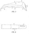
- an embodiment of the shell 1 has an outer contact or bearing surface 2 which is generally planar with peripheral sloping or bevelled sides 3, 4 and ends 6, 8. Other embodiments may have a convex curved bearing surface or faceted contour surface.
- the outer bearing surface 2 is provided with injection inlet ports 5.
- the shell has peripheral edges 13, 14 adapted to allow passage of a flowable material. Provision of recesses 23, 24 in portions of the peripheral edges 13, 14 provides a series of apertures when the peripheral edges 13, 14 are in contact with a parallel surface.
- an inner surface 12 of the shell 1 is configured to provide a plurality of curved ridges 15, or fish scale pattern, to provide a keying surface to improve adhesion or bonding with a bonding material.
- the shell is formed to include structural reinforcements such as one or more integral strengthening struts, braces or ribs 16 extending from one side 3 to an opposite side 4.
- structural reinforcements such as one or more integral strengthening struts, braces or ribs 16 extending from one side 3 to an opposite side 4.
- One such transverse strut 16 is shown in Fig. 1 .
- a selected outer surface area of a tubular 10 is prepared in order to provide a clean, dry substrate with an appropriate surface profile for receiving the shell.
- a prefabricated shell 1 of appropriate dimensions is presented to the prepared area, so that edges 13 and 14 are contiguous with the surface of the tubular.
- the shell 1 is held in position temporarily by use of releasable fastenings such as removable straps, or adhesive tape.
- a cavity is thereby defined between interior surfaces of the shell 1 and the prepared area of the tubular.
- a bonding material is injected into the shell cavity through one or more inlet ports 5 in the surface of the shell 1 until it flows through the apertures defined between the recesses 23, 24 and the surface of the tubular.
- the straps and/or adhesive tape may be removed.
- the prefabricated shell becomes an integral part of the positioning member bonded to the tubular.
- the tubular is thereby modified to have a surface mounted positioning member which facilitates appropriate positioning of the tubular in a borehole.
- Additional positioning members may be formed on the tubular by repetition of the above described methods and procedures.
Description
- Oil and gas reservoirs may be exploited by tapping the resources therein via wellbores. Drilling of wellbores may require drilling a considerable distance into the earth. Many oil & gas bearing formations are at sub-sea locations. The direction of drilling may vary from a vertical position to a horizontal position. The wellbore created by drilling may be stabilised by use of casing or lining or by other measures. Tubular bodies (hereinafter "tubulars") may be positioned in the wellbore. The tubular bodies may be cemented into position. The positioning of tubulars in the wellbore may be complicated by variations in wellbore direction. Tubulars may have mechanical components mounted thereon for the purposes of improving alignment and stable positioning of the tubulars in the wellbore. Correct positioning of the tubulars permits cementing to a satisfactory standard.
-
US4146060 discloses a drill pipe wear belt assembly. A steel wear belt having a prepared inner surface with an inner diameter large enough to pass over the weld upset on one end of a drill pipe tube but too small to pass over the tool joint is installed about the pipe over a prepared outer peripheral surface thereof.GB2406591 - The tubular of the invention is as defined in claim 1. A corresponding method of the invention is as defined in
claim 13. A positioning member is formed and applied to a tubular. The forming process comprises prefabrication of an outer part followed by application and bonding of the outer part to the tubular. The formed positioning member provides a protrusion upon the surface of the tubular. - The positioning member comprises a shell configured to a desired external shape. The external shape of the shell may be configured to form straight, curved, helical or spiral shaped positioning members. The shell has an external contact or bearing surface, which may be generally planar or outwardly curved (convex), with bevelled side surfaces. The shell may have peripheral edges including portions adapted to allow passage of a flowable material. The peripheral edge portions may be indented, recessed, notched, serrated, apertured, crenulated, slotted or otherwise include a discontinuity which may form a flow port when the peripheral edge is presented against a parallel surface. The depth of the shell is selected to provide a clearance or spaced position from a surface such as the wall of a borehole.
- The interior surface of the shell may be configured to provide a plurality of projections, curved ridges, a fish scale pattern or any other relief pattern.
- The shell may be structurally reinforced by provision of one or more strengthening members. The strengthening member may be a strut, brace, a rib or an equivalent thereof. Such structural reinforcement may extend between two opposite sides of the shell.
- The shell may be formed from a composite material. The composite material may be a fibre-reinforced resin material (FRP/GRP/GFK type material). The resin material is a hardenable resin optionally including curing agents and curing modifiers. The resin may be self-curing, or provided in two components which harden when brought together. The two component system may be a matrix-forming (pre-polymer) component and a hardener. Suitable resins include epoxy resins, polyurethanes and polyurea resins including blends or hybrids thereof, and other curable resin components including polyester or polyol or polyamine components. The curing of the resin may be controlled by use of amine curing agents such as polyetheramines. Other additives may be present.
- The fibre-reinforced resin material may be surface treated before moulding of the shell. The fibre-reinforced resin material may have a ceramic particulate applied. The fibre-reinforced material may have a friction-modifying material applied. A combination of such surface treatments may be used. The surface treatment may be a surface modifying finish to an external surface of the moulded shell.
- Additional particulate materials may be present within the bulk of the fibre-reinforced resin material. The particulates may be in bead form.
- The shell may have at least one inlet for passage of flowable materials, such as bonding agents. The shell may be bonded to an external surface of a tubular. Bonding agents may be introduced into a void between the tubular and the shell by injection through the at least one inlet.
- The shell may be temporarily located upon a tubular, prior to introducing bonding agents into the shell, using temporary fastenings so as to enclose a void between the tubular and the shell. The temporary fastenings may be a contact adhesive or releasable fasteners which may include ties, wires, straps, an adhesive tape and various combinations thereof.
- Embodiments incorporate the disclosed summary features individually or in a variety of combinations.
-
-
Figure 1 is a perspective view from below and to one side of a fibre reinforced composite shell body; -
Figure 2 is a perspective view form above and to one side of a fibre reinforced composite shell body; -
Figure 3 is a perspective view from one end of a fibre reinforced composite shell body; and -
Figure 4 is a side view of a tubular modified by application of fibre reinforced composite shell bodies. - In an embodiment, a permanent mould or form is designed and constructed according to shape requirements for the shell form to be manufactured, that is, the geometry required for the intended positioning member. The shape requirements are derived from known dimensions of a tubular and its intended use in a wellbore. A choice can be made amongst protrusions of straight, curved or spiral or helical configurations. A number of differing moulds may be produced to enable a variety of positioning members to be manufactured at will.
- The mould is used to form materials into a prefabricated shell which is suitable to form part of a positioning member which is to be provide on a tubular.
- In an embodiment, a fibre mat is infused with a resin matrix. This is achievable by passing the fibre mat through a bath containing the resin matrix. Infusion may also be achievable in other ways, such as applying the resin matrix liberally to the fibre mat by pouring or spraying or by a pressure treatment to soak, or impregnate the fibre mat with the resin matrix.
- Ceramic particulates, for example hard wearing materials such as a combination of zirconium dioxide and silicon nitride, optionally in bead form, may be applied to the resin matrix infused fibre mat.
- A friction modifying material such as fluorocarbon particulates providing a low friction coefficient also may be applied to the resin matrix infused mat.
- The resin matrix infused fibre mat may be introduced to the mould such that surfaces treated with the aforesaid particulates are adjacent to the mould surfaces. Multiple additional layers of the resin matrix infused fibre mat, which may or may not each have been treated with particulates, may be laid up into the mould on to the first resin matrix infused fibre mat lining the mould until a predetermined thickness is attained.
- Then the mould may be closed.
- A resin filler matrix may be introduced into the mould using a low pressure resin transfer moulding process. In an example of such a process, a mixed resin and catalyst or resin curing agent are introduced, for example by injection, into a closed mould containing a resin matrix infused fibre and particulates lay up. In this way a composite shell may be formed.
- The mould may be heated in order to achieve first cure.
- After sufficient curing of the resin to permit handling of the shell, the mould can be opened and the formed shell removed.
- If necessary a post cure of the formed shell may be carried out. Post cure may be a heat treatment, for example conducted in an oven.
- Referring to
Fig. 2 , an embodiment of the shell 1 has an outer contact or bearingsurface 2 which is generally planar with peripheral sloping orbevelled sides outer bearing surface 2 is provided withinjection inlet ports 5. - Referring to
Fig. 1 , the shell hasperipheral edges recesses peripheral edges peripheral edges - Referring to
Fig. 1 , aninner surface 12 of the shell 1 is configured to provide a plurality ofcurved ridges 15, or fish scale pattern, to provide a keying surface to improve adhesion or bonding with a bonding material. - Optionally, the shell is formed to include structural reinforcements such as one or more integral strengthening struts, braces or
ribs 16 extending from oneside 3 to anopposite side 4. One suchtransverse strut 16 is shown inFig. 1 . - In use of the shell 1 to form a
positioning member 11, a selected outer surface area of a tubular 10 is prepared in order to provide a clean, dry substrate with an appropriate surface profile for receiving the shell. - A prefabricated shell 1 of appropriate dimensions is presented to the prepared area, so that edges 13 and 14 are contiguous with the surface of the tubular. The shell 1 is held in position temporarily by use of releasable fastenings such as removable straps, or adhesive tape. A cavity is thereby defined between interior surfaces of the shell 1 and the prepared area of the tubular.
- A bonding material is injected into the shell cavity through one or
more inlet ports 5 in the surface of the shell 1 until it flows through the apertures defined between therecesses - When a period sufficient for curing of the bonding material has elapsed, the straps and/or adhesive tape may be removed.
- By this method the prefabricated shell becomes an integral part of the positioning member bonded to the tubular.
- The tubular is thereby modified to have a surface mounted positioning member which facilitates appropriate positioning of the tubular in a borehole.
- Additional positioning members may be formed on the tubular by repetition of the above described methods and procedures.
Claims (14)
- A tubular (10) having at least one positioning member (11) bonded thereto so as to facilitate appropriate positioning of the tubular (10) in a borehole, wherein the positioning member comprises:a prefabricated composite shell (1) having an external bearing surface (2) with bevelled side surfaces (3, 4) and ends (6, 8); anda cured bonding material for bonding the prefabricated composite shell (1) to the tubular (10), the bonding material being placed in a shell cavity formed between a surface of the tubular and the prefabricated composite shell, wherein the cured bonding material substantially fills the interior of the prefabricated composite shell (1).
- The tubular (10) claimed in claim 1, wherein the prefabricated composite shell (1) is formed from a composite material and has a surface comprising particulates conferring surface abrasion resistance properties.
- The tubular (10) claimed in claim 1, wherein the prefabricated composite shell (1) is formed from a composite material and has a surface comprising particulates conferring low friction coefficient properties.
- The tubular (10) claimed in claim 1, wherein the prefabricated composite shell (1) is formed from a composite material and has a surface comprising particulates conferring surface abrasion resistance and particulates conferring low friction coefficient properties.
- The tubular (10) claimed in claim 1 wherein the prefabricated composite shell (1) comprises a fibre reinforced mat infused with a resin matrix, and the fibre reinforced mat infused with a resin matrix has ceramic particulates on at least a surface thereof.
- The tubular (10) claimed in claim 5, wherein the fibre reinforced mat infused with a resin matrix has friction reducing fluorocarbon particulates on at least a surface thereof.
- The tubular (10) claimed in claim 5, wherein particulate materials are provided within the fibre reinforced mat infused with a resin matrix.
- The tubular (10) claimed in claim 7, wherein the particulate materials provided within the fibre reinforced mat infused with a resin matrix are selected from the group consisting of particulates conferring surface abrasion resistance and particulates conferring low friction coefficient properties.
- The tubular (10) claimed in claim 1, wherein the prefabricated composite shell (1) comprises ceramic beads on at least one outer surface thereof.
- The tubular (10) claimed in claim 9, wherein the ceramic beads comprise zirconium dioxide and silicon nitride.
- The tubular (10) claimed in claim 1, wherein the prefabricated composite shell (1) has an external planar bearing surface (2).
- The tubular (10) claimed in claim 1, wherein the prefabricated composite shell (1) has an external convex curved bearing surface (2).
- A method comprising forming a positioning member (11) on a tubular (10) so as to facilitate appropriate positioning of the tubular (10) in a borehole, wherein forming the positioning member (11) on the tubular (10) comprises:applying a prefabricated composite shell (1) to a surface of the tubular, the prefabricated composite shell having an external bearing surface (2) with bevelled side surfaces (3, 4) and ends (6, 8);introducing bonding material to a cavity formed between the surface of the tubular and the prefabricated composite shell; andcuring the bonding material, wherein the cured bonding material substantially fills the interior of the prefabricated composite shell (1).
- The method claimed in claim 13, wherein the prefabricated composite shell (1) is formed from a composite material and has an external surface comprising particulates selected from the group consisting of particulates conferring surface abrasion resistance and particulates conferring low friction coefficient properties.
Applications Claiming Priority (2)
| Application Number | Priority Date | Filing Date | Title |
|---|---|---|---|
| GB201215868A GB2506845B (en) | 2012-09-05 | 2012-09-05 | Modified tubular |
| PCT/EP2013/057416 WO2014037125A2 (en) | 2012-09-05 | 2013-04-09 | Modified tubular |
Publications (2)
| Publication Number | Publication Date |
|---|---|
| EP2893121A2 EP2893121A2 (en) | 2015-07-15 |
| EP2893121B1 true EP2893121B1 (en) | 2018-08-22 |
Family
ID=47136991
Family Applications (1)
| Application Number | Title | Priority Date | Filing Date |
|---|---|---|---|
| EP13722299.8A Active EP2893121B1 (en) | 2012-09-05 | 2013-04-09 | Modified tubular |
Country Status (7)
| Country | Link |
|---|---|
| US (2) | US9376871B2 (en) |
| EP (1) | EP2893121B1 (en) |
| AU (1) | AU2013311983B2 (en) |
| CA (1) | CA2883854C (en) |
| DK (1) | DK2893121T3 (en) |
| GB (1) | GB2506845B (en) |
| WO (1) | WO2014037125A2 (en) |
Families Citing this family (7)
| Publication number | Priority date | Publication date | Assignee | Title |
|---|---|---|---|---|
| WO2010118186A2 (en) | 2009-04-07 | 2010-10-14 | Frank's International, Inc. | Friction reducing wear band and method of coupling a wear band to a tubular |
| GB2506845B (en) * | 2012-09-05 | 2015-01-14 | Advanced Composite Ind Ag | Modified tubular |
| WO2015031644A1 (en) | 2013-08-28 | 2015-03-05 | Antelope Oil Tool & Mfg. Co., Llc | Chromium-free thermal spray composition, method, and apparatus |
| US11072979B2 (en) | 2014-10-22 | 2021-07-27 | X-Holding Gmbh | Cable clamp |
| EP3247865A4 (en) * | 2014-12-31 | 2018-09-26 | Antelope Oil Tool & Mfg. Co., LLC | Turned-down centralizer sub assembly |
| US10584553B2 (en) | 2016-04-28 | 2020-03-10 | Innovex Downhole Solutions, Inc. | Integrally-bonded swell packer |
| WO2018170038A2 (en) * | 2017-03-14 | 2018-09-20 | Antelope Oil Tool & Mfg. Co., Llc | Expansion chamber |
Family Cites Families (16)
| Publication number | Priority date | Publication date | Assignee | Title |
|---|---|---|---|---|
| US4146060A (en) * | 1977-07-25 | 1979-03-27 | Smith International, Inc. | Drill pipe wear belt assembly |
| US4634314A (en) * | 1984-06-26 | 1987-01-06 | Vetco Offshore Inc. | Composite marine riser system |
| NO953303L (en) | 1994-08-26 | 1996-02-27 | Halliburton Co | Composite well production tubes |
| AUPN559095A0 (en) * | 1995-09-22 | 1995-10-19 | Cherrington (Australia) Pty Ltd | Pipe protector |
| US5697442A (en) * | 1995-11-13 | 1997-12-16 | Halliburton Company | Apparatus and methods for use in cementing a casing string within a well bore |
| GB0001435D0 (en) * | 2000-01-22 | 2000-03-08 | Downhole Products Plc | Centraliser |
| GB0016146D0 (en) * | 2000-06-30 | 2000-08-23 | Brunel Oilfield Serv Uk Ltd | Improvements in or relating to downhole tools |
| US20050224123A1 (en) | 2002-08-12 | 2005-10-13 | Baynham Richard R | Integral centraliser |
| GB2406591B (en) | 2003-09-17 | 2006-11-08 | Karl Schmidt | Centraliser formed from composite material for drill or production strings |
| GB0521478D0 (en) * | 2005-10-21 | 2005-11-30 | Stewart Grant | Improvements to wear resistance |
| US20070284037A1 (en) | 2006-06-07 | 2007-12-13 | Jean Buytaert | Epoxy secured stop collar for centralizer |
| GB0621892D0 (en) * | 2006-11-03 | 2006-12-13 | Polyoil Ltd | Downhole apparatus and method of forming the same |
| CA2749602C (en) * | 2009-11-13 | 2014-01-28 | Wwt International, Inc. | Open hole non-rotating sleeve and assembly |
| US8833446B2 (en) | 2011-01-25 | 2014-09-16 | Halliburton Energy Services, Inc. | Composite bow centralizer |
| GB2490924B (en) * | 2011-05-18 | 2013-07-10 | Volnay Engineering Services Ltd | Improvements in and relating to downhole tools |
| GB2506845B (en) * | 2012-09-05 | 2015-01-14 | Advanced Composite Ind Ag | Modified tubular |
-
2012
- 2012-09-05 GB GB201215868A patent/GB2506845B/en active Active
-
2013
- 2013-04-09 EP EP13722299.8A patent/EP2893121B1/en active Active
- 2013-04-09 DK DK13722299.8T patent/DK2893121T3/en active
- 2013-04-09 AU AU2013311983A patent/AU2013311983B2/en active Active
- 2013-04-09 US US14/374,442 patent/US9376871B2/en active Active
- 2013-04-09 WO PCT/EP2013/057416 patent/WO2014037125A2/en active Application Filing
- 2013-04-09 CA CA2883854A patent/CA2883854C/en active Active
-
2015
- 2015-01-08 US US14/592,464 patent/US9404317B2/en active Active
Non-Patent Citations (1)
| Title |
|---|
| None * |
Also Published As
| Publication number | Publication date |
|---|---|
| CA2883854C (en) | 2020-06-02 |
| AU2013311983A1 (en) | 2015-03-26 |
| US20150122484A1 (en) | 2015-05-07 |
| GB2506845A (en) | 2014-04-16 |
| US9376871B2 (en) | 2016-06-28 |
| GB201215868D0 (en) | 2012-10-24 |
| EP2893121A2 (en) | 2015-07-15 |
| GB2506845B (en) | 2015-01-14 |
| WO2014037125A3 (en) | 2014-08-28 |
| WO2014037125A2 (en) | 2014-03-13 |
| US9404317B2 (en) | 2016-08-02 |
| AU2013311983B2 (en) | 2017-12-14 |
| DK2893121T3 (en) | 2018-12-10 |
| CA2883854A1 (en) | 2014-03-13 |
| US20140367085A1 (en) | 2014-12-18 |
Similar Documents
| Publication | Publication Date | Title |
|---|---|---|
| EP2893121B1 (en) | Modified tubular | |
| MX2013008581A (en) | Composite bow centralizer. | |
| EP2855828B1 (en) | Pull through centralizer | |
| MX2013008579A (en) | Composite bow centralizer. | |
| AU2012312821B2 (en) | Composite limit collar | |
| MX2014013898A (en) | Pull through centralizer. | |
| US10113373B2 (en) | Centraliser | |
| US11230892B2 (en) | Modified tubular | |
| EP3239455B1 (en) | Integrally-bonded swell packer | |
| EP3596306B1 (en) | Expansion chamber | |
| US9926748B2 (en) | Modified tubular with wireless communication device |
Legal Events
| Date | Code | Title | Description |
|---|---|---|---|
| PUAI | Public reference made under article 153(3) epc to a published international application that has entered the european phase |
Free format text: ORIGINAL CODE: 0009012 |
|
| 17P | Request for examination filed |
Effective date: 20150402 |
|
| AK | Designated contracting states |
Kind code of ref document: A2 Designated state(s): AL AT BE BG CH CY CZ DE DK EE ES FI FR GB GR HR HU IE IS IT LI LT LU LV MC MK MT NL NO PL PT RO RS SE SI SK SM TR |
|
| AX | Request for extension of the european patent |
Extension state: BA ME |
|
| 17Q | First examination report despatched |
Effective date: 20151110 |
|
| DAX | Request for extension of the european patent (deleted) | ||
| STAA | Information on the status of an ep patent application or granted ep patent |
Free format text: STATUS: EXAMINATION IS IN PROGRESS |
|
| RAP1 | Party data changed (applicant data changed or rights of an application transferred) |
Owner name: ANTELOPE OIL TOOLS SWITZERLAND AG |
|
| GRAP | Despatch of communication of intention to grant a patent |
Free format text: ORIGINAL CODE: EPIDOSNIGR1 |
|
| STAA | Information on the status of an ep patent application or granted ep patent |
Free format text: STATUS: GRANT OF PATENT IS INTENDED |
|
| INTG | Intention to grant announced |
Effective date: 20180320 |
|
| GRAS | Grant fee paid |
Free format text: ORIGINAL CODE: EPIDOSNIGR3 |
|
| GRAA | (expected) grant |
Free format text: ORIGINAL CODE: 0009210 |
|
| STAA | Information on the status of an ep patent application or granted ep patent |
Free format text: STATUS: THE PATENT HAS BEEN GRANTED |
|
| RBV | Designated contracting states (corrected) |
Designated state(s): AL AT BE BG CH CY CZ DE DK EE ES FI FR GR HR HU IE IS IT LI LT LU LV MC MK MT NL NO PL PT RO RS SE SI SK SM TR |
|
| AK | Designated contracting states |
Kind code of ref document: B1 Designated state(s): AL AT BE BG CH CY CZ DE DK EE ES FI FR GR HR HU IE IS IT LI LT LU LV MC MK MT NL NO PL PT RO RS SE SI SK SM TR |
|
| REG | Reference to a national code |
Ref country code: CH Ref legal event code: EP |
|
| REG | Reference to a national code |
Ref country code: AT Ref legal event code: REF Ref document number: 1032745 Country of ref document: AT Kind code of ref document: T Effective date: 20180915 |
|
| REG | Reference to a national code |
Ref country code: IE Ref legal event code: FG4D |
|
| REG | Reference to a national code |
Ref country code: DE Ref legal event code: R096 Ref document number: 602013042366 Country of ref document: DE |
|
| REG | Reference to a national code |
Ref country code: NL Ref legal event code: FP |
|
| REG | Reference to a national code |
Ref country code: NO Ref legal event code: T2 Effective date: 20180822 |
|
| REG | Reference to a national code |
Ref country code: DK Ref legal event code: T3 Effective date: 20181203 |
|
| REG | Reference to a national code |
Ref country code: LT Ref legal event code: MG4D |
|
| PG25 | Lapsed in a contracting state [announced via postgrant information from national office to epo] |
Ref country code: RS Free format text: LAPSE BECAUSE OF FAILURE TO SUBMIT A TRANSLATION OF THE DESCRIPTION OR TO PAY THE FEE WITHIN THE PRESCRIBED TIME-LIMIT Effective date: 20180822 Ref country code: IS Free format text: LAPSE BECAUSE OF FAILURE TO SUBMIT A TRANSLATION OF THE DESCRIPTION OR TO PAY THE FEE WITHIN THE PRESCRIBED TIME-LIMIT Effective date: 20181222 Ref country code: SE Free format text: LAPSE BECAUSE OF FAILURE TO SUBMIT A TRANSLATION OF THE DESCRIPTION OR TO PAY THE FEE WITHIN THE PRESCRIBED TIME-LIMIT Effective date: 20180822 Ref country code: GR Free format text: LAPSE BECAUSE OF FAILURE TO SUBMIT A TRANSLATION OF THE DESCRIPTION OR TO PAY THE FEE WITHIN THE PRESCRIBED TIME-LIMIT Effective date: 20181123 Ref country code: FI Free format text: LAPSE BECAUSE OF FAILURE TO SUBMIT A TRANSLATION OF THE DESCRIPTION OR TO PAY THE FEE WITHIN THE PRESCRIBED TIME-LIMIT Effective date: 20180822 Ref country code: BG Free format text: LAPSE BECAUSE OF FAILURE TO SUBMIT A TRANSLATION OF THE DESCRIPTION OR TO PAY THE FEE WITHIN THE PRESCRIBED TIME-LIMIT Effective date: 20181122 Ref country code: LT Free format text: LAPSE BECAUSE OF FAILURE TO SUBMIT A TRANSLATION OF THE DESCRIPTION OR TO PAY THE FEE WITHIN THE PRESCRIBED TIME-LIMIT Effective date: 20180822 |
|
| PG25 | Lapsed in a contracting state [announced via postgrant information from national office to epo] |
Ref country code: AL Free format text: LAPSE BECAUSE OF FAILURE TO SUBMIT A TRANSLATION OF THE DESCRIPTION OR TO PAY THE FEE WITHIN THE PRESCRIBED TIME-LIMIT Effective date: 20180822 Ref country code: HR Free format text: LAPSE BECAUSE OF FAILURE TO SUBMIT A TRANSLATION OF THE DESCRIPTION OR TO PAY THE FEE WITHIN THE PRESCRIBED TIME-LIMIT Effective date: 20180822 Ref country code: LV Free format text: LAPSE BECAUSE OF FAILURE TO SUBMIT A TRANSLATION OF THE DESCRIPTION OR TO PAY THE FEE WITHIN THE PRESCRIBED TIME-LIMIT Effective date: 20180822 |
|
| PG25 | Lapsed in a contracting state [announced via postgrant information from national office to epo] |
Ref country code: EE Free format text: LAPSE BECAUSE OF FAILURE TO SUBMIT A TRANSLATION OF THE DESCRIPTION OR TO PAY THE FEE WITHIN THE PRESCRIBED TIME-LIMIT Effective date: 20180822 Ref country code: PL Free format text: LAPSE BECAUSE OF FAILURE TO SUBMIT A TRANSLATION OF THE DESCRIPTION OR TO PAY THE FEE WITHIN THE PRESCRIBED TIME-LIMIT Effective date: 20180822 Ref country code: RO Free format text: LAPSE BECAUSE OF FAILURE TO SUBMIT A TRANSLATION OF THE DESCRIPTION OR TO PAY THE FEE WITHIN THE PRESCRIBED TIME-LIMIT Effective date: 20180822 Ref country code: CZ Free format text: LAPSE BECAUSE OF FAILURE TO SUBMIT A TRANSLATION OF THE DESCRIPTION OR TO PAY THE FEE WITHIN THE PRESCRIBED TIME-LIMIT Effective date: 20180822 Ref country code: ES Free format text: LAPSE BECAUSE OF FAILURE TO SUBMIT A TRANSLATION OF THE DESCRIPTION OR TO PAY THE FEE WITHIN THE PRESCRIBED TIME-LIMIT Effective date: 20180822 |
|
| REG | Reference to a national code |
Ref country code: DE Ref legal event code: R097 Ref document number: 602013042366 Country of ref document: DE |
|
| PG25 | Lapsed in a contracting state [announced via postgrant information from national office to epo] |
Ref country code: SK Free format text: LAPSE BECAUSE OF FAILURE TO SUBMIT A TRANSLATION OF THE DESCRIPTION OR TO PAY THE FEE WITHIN THE PRESCRIBED TIME-LIMIT Effective date: 20180822 Ref country code: SM Free format text: LAPSE BECAUSE OF FAILURE TO SUBMIT A TRANSLATION OF THE DESCRIPTION OR TO PAY THE FEE WITHIN THE PRESCRIBED TIME-LIMIT Effective date: 20180822 |
|
| PLBE | No opposition filed within time limit |
Free format text: ORIGINAL CODE: 0009261 |
|
| STAA | Information on the status of an ep patent application or granted ep patent |
Free format text: STATUS: NO OPPOSITION FILED WITHIN TIME LIMIT |
|
| 26N | No opposition filed |
Effective date: 20190523 |
|
| PG25 | Lapsed in a contracting state [announced via postgrant information from national office to epo] |
Ref country code: SI Free format text: LAPSE BECAUSE OF FAILURE TO SUBMIT A TRANSLATION OF THE DESCRIPTION OR TO PAY THE FEE WITHIN THE PRESCRIBED TIME-LIMIT Effective date: 20180822 |
|
| REG | Reference to a national code |
Ref country code: DE Ref legal event code: R082 Ref document number: 602013042366 Country of ref document: DE Representative=s name: HASELTINE LAKE KEMPNER LLP, DE Ref country code: DE Ref legal event code: R081 Ref document number: 602013042366 Country of ref document: DE Owner name: INNOVEX DOWNHOLE SOLUTIONS INC., THE WOODLANDS, US Free format text: FORMER OWNER: ANTELOPE OIL TOOLS SWITZERLAND AG, KASTANIENBAUM, CH Ref country code: DE Ref legal event code: R082 Ref document number: 602013042366 Country of ref document: DE Representative=s name: HL KEMPNER PATENTANWALT, RECHTSANWALT, SOLICIT, DE Ref country code: DE Ref legal event code: R081 Ref document number: 602013042366 Country of ref document: DE Owner name: X-HOLDING GMBH, DE Free format text: FORMER OWNER: ANTELOPE OIL TOOLS SWITZERLAND AG, KASTANIENBAUM, CH Ref country code: DE Ref legal event code: R082 Ref document number: 602013042366 Country of ref document: DE Representative=s name: MURGITROYD & COMPANY, DE |
|
| REG | Reference to a national code |
Ref country code: NO Ref legal event code: CHAD Owner name: INNOVEX DOWNHOLE SOLUTIONS, US |
|
| REG | Reference to a national code |
Ref country code: BE Ref legal event code: MM Effective date: 20190430 |
|
| PG25 | Lapsed in a contracting state [announced via postgrant information from national office to epo] |
Ref country code: LU Free format text: LAPSE BECAUSE OF NON-PAYMENT OF DUE FEES Effective date: 20190409 Ref country code: MC Free format text: LAPSE BECAUSE OF FAILURE TO SUBMIT A TRANSLATION OF THE DESCRIPTION OR TO PAY THE FEE WITHIN THE PRESCRIBED TIME-LIMIT Effective date: 20180822 |
|
| REG | Reference to a national code |
Ref country code: AT Ref legal event code: PC Ref document number: 1032745 Country of ref document: AT Kind code of ref document: T Owner name: INNOVEX DOWNHOLE SOLUTIONS INC., US Effective date: 20191223 |
|
| PG25 | Lapsed in a contracting state [announced via postgrant information from national office to epo] |
Ref country code: BE Free format text: LAPSE BECAUSE OF NON-PAYMENT OF DUE FEES Effective date: 20190430 |
|
| PG25 | Lapsed in a contracting state [announced via postgrant information from national office to epo] |
Ref country code: TR Free format text: LAPSE BECAUSE OF FAILURE TO SUBMIT A TRANSLATION OF THE DESCRIPTION OR TO PAY THE FEE WITHIN THE PRESCRIBED TIME-LIMIT Effective date: 20180822 |
|
| REG | Reference to a national code |
Ref country code: CH Ref legal event code: NV Representative=s name: DR. LUSUARDI AG, CH Ref country code: CH Ref legal event code: PUE Owner name: INNOVEX DOWNHOLE SOLUTIONS, INC., US Free format text: FORMER OWNER: ANTELOPE OIL TOOLS SWITZERLAND AG, CH |
|
| PG25 | Lapsed in a contracting state [announced via postgrant information from national office to epo] |
Ref country code: IE Free format text: LAPSE BECAUSE OF NON-PAYMENT OF DUE FEES Effective date: 20190409 |
|
| REG | Reference to a national code |
Ref country code: NL Ref legal event code: PD Owner name: INNOVEX DOWNHOLE SOLUTIONS, INC.; US Free format text: DETAILS ASSIGNMENT: CHANGE OF OWNER(S), ASSIGNMENT; FORMER OWNER NAME: ANTELOPE OIL TOOLS SWITZERLAND AG Effective date: 20200513 |
|
| PG25 | Lapsed in a contracting state [announced via postgrant information from national office to epo] |
Ref country code: PT Free format text: LAPSE BECAUSE OF FAILURE TO SUBMIT A TRANSLATION OF THE DESCRIPTION OR TO PAY THE FEE WITHIN THE PRESCRIBED TIME-LIMIT Effective date: 20181222 |
|
| REG | Reference to a national code |
Ref country code: DE Ref legal event code: R082 Ref document number: 602013042366 Country of ref document: DE Representative=s name: MURGITROYD GERMANY PATENTANWALTSGESELLSCHAFT M, DE Ref country code: DE Ref legal event code: R082 Ref document number: 602013042366 Country of ref document: DE Representative=s name: HL KEMPNER PATENTANWALT, RECHTSANWALT, SOLICIT, DE Ref country code: DE Ref legal event code: R082 Ref document number: 602013042366 Country of ref document: DE Representative=s name: MURGITROYD & COMPANY, DE |
|
| PG25 | Lapsed in a contracting state [announced via postgrant information from national office to epo] |
Ref country code: CY Free format text: LAPSE BECAUSE OF FAILURE TO SUBMIT A TRANSLATION OF THE DESCRIPTION OR TO PAY THE FEE WITHIN THE PRESCRIBED TIME-LIMIT Effective date: 20180822 |
|
| REG | Reference to a national code |
Ref country code: DE Ref legal event code: R082 Ref document number: 602013042366 Country of ref document: DE Representative=s name: MURGITROYD GERMANY PATENTANWALTSGESELLSCHAFT M, DE Ref country code: DE Ref legal event code: R082 Ref document number: 602013042366 Country of ref document: DE Representative=s name: MURGITROYD & COMPANY, DE Ref country code: DE Ref legal event code: R081 Ref document number: 602013042366 Country of ref document: DE Owner name: X-HOLDING GMBH, DE Free format text: FORMER OWNER: INNOVEX DOWNHOLE SOLUTIONS INC., THE WOODLANDS, TX, US |
|
| PG25 | Lapsed in a contracting state [announced via postgrant information from national office to epo] |
Ref country code: MT Free format text: LAPSE BECAUSE OF FAILURE TO SUBMIT A TRANSLATION OF THE DESCRIPTION OR TO PAY THE FEE WITHIN THE PRESCRIBED TIME-LIMIT Effective date: 20180822 Ref country code: HU Free format text: LAPSE BECAUSE OF FAILURE TO SUBMIT A TRANSLATION OF THE DESCRIPTION OR TO PAY THE FEE WITHIN THE PRESCRIBED TIME-LIMIT; INVALID AB INITIO Effective date: 20130409 |
|
| REG | Reference to a national code |
Ref country code: AT Ref legal event code: PC Ref document number: 1032745 Country of ref document: AT Kind code of ref document: T Owner name: X-HOLDING GMBH, DE Effective date: 20210802 |
|
| REG | Reference to a national code |
Ref country code: NO Ref legal event code: CREP Representative=s name: MURGITROYD & COMPANY, MANNERHEIMVAEGEN 12 B, 5TR Ref country code: NO Ref legal event code: CHAD Owner name: X-HOLDING GMBH, DE |
|
| REG | Reference to a national code |
Ref country code: AT Ref legal event code: UEP Ref document number: 1032745 Country of ref document: AT Kind code of ref document: T Effective date: 20180822 |
|
| PG25 | Lapsed in a contracting state [announced via postgrant information from national office to epo] |
Ref country code: MK Free format text: LAPSE BECAUSE OF FAILURE TO SUBMIT A TRANSLATION OF THE DESCRIPTION OR TO PAY THE FEE WITHIN THE PRESCRIBED TIME-LIMIT Effective date: 20180822 |
|
| PGFP | Annual fee paid to national office [announced via postgrant information from national office to epo] |
Ref country code: NL Payment date: 20230427 Year of fee payment: 11 |
|
| PGFP | Annual fee paid to national office [announced via postgrant information from national office to epo] |
Ref country code: NO Payment date: 20230503 Year of fee payment: 11 Ref country code: IT Payment date: 20230428 Year of fee payment: 11 Ref country code: FR Payment date: 20230428 Year of fee payment: 11 Ref country code: DK Payment date: 20230428 Year of fee payment: 11 Ref country code: DE Payment date: 20230428 Year of fee payment: 11 Ref country code: CH Payment date: 20230502 Year of fee payment: 11 |
|
| PGFP | Annual fee paid to national office [announced via postgrant information from national office to epo] |
Ref country code: AT Payment date: 20230502 Year of fee payment: 11 |