EP2892699B1 - Power operated dermatome with rotary knife blade - Google Patents
Power operated dermatome with rotary knife blade Download PDFInfo
- Publication number
- EP2892699B1 EP2892699B1 EP13835651.4A EP13835651A EP2892699B1 EP 2892699 B1 EP2892699 B1 EP 2892699B1 EP 13835651 A EP13835651 A EP 13835651A EP 2892699 B1 EP2892699 B1 EP 2892699B1
- Authority
- EP
- European Patent Office
- Prior art keywords
- depth gauge
- blade
- rotary knife
- assembly
- depth
- Prior art date
- Legal status (The legal status is an assumption and is not a legal conclusion. Google has not performed a legal analysis and makes no representation as to the accuracy of the status listed.)
- Active
Links
Images







Classifications
-
- A—HUMAN NECESSITIES
- A61—MEDICAL OR VETERINARY SCIENCE; HYGIENE
- A61B—DIAGNOSIS; SURGERY; IDENTIFICATION
- A61B17/00—Surgical instruments, devices or methods
- A61B17/32—Surgical cutting instruments
- A61B17/322—Skin grafting apparatus
-
- B—PERFORMING OPERATIONS; TRANSPORTING
- B26—HAND CUTTING TOOLS; CUTTING; SEVERING
- B26B—HAND-HELD CUTTING TOOLS NOT OTHERWISE PROVIDED FOR
- B26B25/00—Hand cutting tools involving disc blades, e.g. motor-driven
- B26B25/002—Motor-driven knives with a rotating annular blade
-
- A—HUMAN NECESSITIES
- A61—MEDICAL OR VETERINARY SCIENCE; HYGIENE
- A61B—DIAGNOSIS; SURGERY; IDENTIFICATION
- A61B90/00—Instruments, implements or accessories specially adapted for surgery or diagnosis and not covered by any of the groups A61B1/00 - A61B50/00, e.g. for luxation treatment or for protecting wound edges
- A61B90/03—Automatic limiting or abutting means, e.g. for safety
- A61B2090/033—Abutting means, stops, e.g. abutting on tissue or skin
-
- A—HUMAN NECESSITIES
- A61—MEDICAL OR VETERINARY SCIENCE; HYGIENE
- A61B—DIAGNOSIS; SURGERY; IDENTIFICATION
- A61B90/00—Instruments, implements or accessories specially adapted for surgery or diagnosis and not covered by any of the groups A61B1/00 - A61B50/00, e.g. for luxation treatment or for protecting wound edges
- A61B90/03—Automatic limiting or abutting means, e.g. for safety
- A61B2090/033—Abutting means, stops, e.g. abutting on tissue or skin
- A61B2090/036—Abutting means, stops, e.g. abutting on tissue or skin abutting on tissue or skin
Definitions
- the present disclosure relates to a power operated dermatome including a rotary knife blade and depth gauge extending to an interior region of the rotary knife blade for removal of skin tissue for skin grafting and other medical purposes.
- Dermatomes are hand-held surgical instruments used by a physician or medical professional (hereinafter operator) for cutting thin layers or sections of skin tissue. Dermatomes are used in hospitals and other medical facilities for excising or removal of skin tissue from patients in connection with various medical procedures including split-thickness and full-thickness skin grafting, skin debriding (e.g., removal of burned skin tissue), tumor/lesion removal, and breast reduction, among other procedures. Dermatomes are also used in to remove skin tissue from deceased human or animal donors for skin grafting purposes.
- Prior dermatomes included both manual operated and power operated dermatomes.
- Manual dermatomes typically included a fixed blade and a handle projecting from the blade.
- Manual dermatomes were often found tedious to use and prone to operator fatigue, especially when large sections of skin tissue needed to be removed, requiring multiple sections of skin tissue to be removed. For example, a deceased human donor may provide from 0.56-0.84 m 2 (6-9 square feet) of recoverable skin tissue.
- an excised skin section be of uniform or consistent thickness along the longitudinal extent of the skin section and across the width of the skin section.
- the thickness of an excised skin section is dependent on the depth of cut of the dermatome cutting blade.
- Use of manual dermatomes often resulted in excised skin sections of varying thickness and having irregular edges.
- the uniformity of the depth of cut was largely dependent on the skill of the operator. While limited numbers of manual dermatomes continue to be used, power operated dermatomes are favored in procedures where large sections of skin tissue need to be removed in an efficient manner and/or operator fatigue is an issue.
- Prior power operated dermatomes typically included a reciprocating cutting blade disposed at a front or leading edge of the dermatome with a guard or depth gauge to allow the operator to set a depth of cut of the dermatome to remove a desired thickness of skin tissue.
- the blade was typically disposed orthogonally to a rearward extending handle or hand piece of the dermatome. Because the cutting direction of the blade of prior power operated dermatomes was forward facing, such dermatome configurations required the operator to move the dermatome in a direction generally away from the operator's body to excise or cut a section of skin tissue.
- This direction of movement of the operator's hand and the dermatome away from the operator's body is less natural and less precise that a direction of movement of the operator's hand and dermatome toward the operator.
- the position of the dermatome tends to block the area of the skin tissue being excised from the view of the operator. This is especially problematic where the tissue to be removed is adjacent to, for example, a raised or bony prominence of the body that must be carefully navigated around with the cutting edge of the dermatome cutting blade.
- the angle of cut of the dermatome refers to an acute angle between the dermatome cutting blade and the skin tissue being removed or excised. If the angle of cut of the dermatome is too shallow, the desired depth of cut will not be achieved. If the angle of cut of the dermatome is too steep, gouging or trenching of the excised skin tissue will occur. Further, if the angle of cut is changed as the power operated dermatome is moved along the skin tissue, the depth of cut will vary along a longitudinal extent of the excised section of skin tissue.
- the speed or rate of forward movement of prior power operated dermatomes also had to be carefully controlled by the operator. If the speed of the dermatome was too fast or too slow, the depth of cut of the excised skin section may be greater or less than the desired depth of cut as set by the operator using the dermatome depth gauge.
- the operator using a typical prior power operated dermatome also was required to apply considerable pressure to the dermatome to insure that the entire extent or length of the cutting edge of the reciprocating blade remained in contact with the skin tissue.
- the pressure applied by the operator to the dermatome needed to remain constant. If the pressure applied by the operator to the dermatome was too great or too little during a cutting operation, the depth of cut could change and the excised skin section would have portions that were of greater or less depth than the desired depth of cut as set with the dermatome depth gauge. If the pressure applied by the operator to the dermatome was too little, the excised skin tissue may be too thin resulting in holes in the excised skin tissue and/or chattered edges.
- Uniformity in the depth of cut of excised skin sections is especially important in split thickness skin grafts where it desired to remove only the outer epidermis and a portion of the dermis. Desired skin tissue thickness in a thin-type split-thickness skin graft is on the order of 0.127 to 0.304 mm. Thus, there is little margin for error where the desired skin thickness and depth of cut is very thin.
- US 3461557 A discloses a head assembly for a power operated rotary knife with the features of the preamble portion of claim 1.
- a depth control plate is generally convex with respect to its lower surface, and is truncated in the direction of a handle at a stabilizer pin.
- US 4575937 A discloses a similar head assembly for a power operated rotary knife with a depth control plate.
- the depth control plate in the head assembly is generally disk-shaped and is provided with a concave bottom surface and is also truncated in the vicinity of a handle where a supporting post contacts an upper surface of the control plate.
- What is needed is a power operated dermatome wherein obtaining a desired, consistent thickness of an excised skin tissue section is less dependent on operator skill in maintaining a constant, desired angle of cut, speed and pressure on the dermatome.
- a power operated dermatome that reduces operator fatigue when removing large sections of skin tissue.
- a power operated dermatome that facilitates the removal of skin tissue in tight spaces and around boney prominences.
- a power operated dermatome that facilitates improved control of the dermatome by the operator by moving the blade cutting edge along a path toward the operator, instead of moving the blade away from the operator.
- What is needed is a power operated dermatome that allows for improved visibility of the skin site being excised by the operator.
- a power operated dermatome that facilitates removal of very thin layers of skin tissue and tangential excision of burn tissue. What is needed is a power operated dermatome that does not require an additional person involved in the procedure to provide counter-traction at the skin removal site to permit an initial cut to be made by the dermatome.
- the present invention relates to a head assembly for a power operated dermatome, the head assembly comprising the features of claim 1.
- the present invention relates to a power operated dermatome comprising: an elongated handle assembly and a head assembly according to the invention removably coupled to the handle assembly.
- the present disclosure relates to a hand-held, power operated dermatome 100 for medical use in removing a layer of skin tissue SK ( Figures 17-21 ) from a patient or donor in connection with various medical procedures including split-thickness and full-thickness skin grafting, skin debriding, e.g., removal of burned skin tissue, tumor/lesion removal, breast reduction, among other procedures, including removing a layer of skin tissue from a deceased human or animal donor for skin grafting/transplanting purposes.
- skin debriding e.g., removal of burned skin tissue, tumor/lesion removal, breast reduction
- the dermatome 100 of the present disclosure includes an annular rotary knife blade 300 that is driven about a central axis of rotation R at a high rotational speed (on the order of 500 - 1,500 RPM) by a drive assembly 500 of the dermatome 100 and further includes a depth gauge assembly 600 to allow precise setting and adjustment of a depth of cut DOC of the dermatome 100.
- a cutting edge 360 of the rotary knife blade 300 cuts or excises an upper layer of skin tissue SK from a grafting region GR, resulting in an excised section or layer of skin tissue EST, as illustrated in Figures 18-20 .
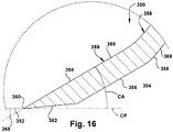
- a cutting angle CA ( Figure7 , 12 , 13 and 16 ) of the blade section 304 adjacent the cutting edge 360 with respect to a cutting plane CP of the rotary knife blade 300 is relatively shallow.
- the cutting angle CA is approximately 30° with respect to the cutting plane CP.
- the depth gauge assembly 600 of the dermatome 100 includes an axially adjustable depth gauge 620.
- the axially adjustable depth gauge 620 includes a depth gauge plate 622 and a depth gauge shaft 640 affixed to the depth gauge plate 622.
- the depth gauge 620 extends into a central opening 301 defined by the rotary knife blade 300.
- An axial position of the depth gauge plate 622 with respect to the cutting edge 360 of the rotary knife blade 300 is determined by a rotation position of a depth adjustment knob 650 of the depth gauge assembly 600.
- the axial position of the gauge plate 622 of the depth gauge 620 with respect to the cutting edge 360 of the rotary knife blade 300 sets the depth of cut DOC of the dermatome 100.
- the depth of cut DOC of the dermatome 100 determines the depth or thickness of a section of skin tissue SK excised by the dermatome 100.
- the depth or thickness of an excised skin tissue section or layer is labeled as DEST in Figures 18-20 . That is, the depth or thickness of an excised skin tissue section DEST of a patient or donor is determined by the depth of cut DOC of the dermatome 100, as precisely set by the operator of the dermatome 100 using the depth adjustment knob 650.
- the high rotary speed of the rotary knife blade 300 of the dermatome 100 of the present disclosure in combination with a shallow cutting angle CA of the knife blade 300 and configuration of the depth gauge assembly 600 and, specifically, the depth gauge plate 622, facilitate an operator's ability to cut or harvest an excised layer of skin tissue EST having a desired depth of cut of the excised tissue DEST that is more uniform and consistent along a longitudinal extend LE ( Figures 18 and 19 ) of the excised skin tissue EST than what would be expected using a prior manual dermatome or a prior power operated dermatome.
- the dermatome 100 of the present disclosure advantageously provides for improved control and manipulation of the dermatome 100 by an operator, using one hand, as the dermatome 100 is moved along a path of travel PT to cut the skin tissue SK to produce the excised skin section EST.
- the high rotary speed of the rotary knife blade 300 of the dermatome 100 reduces operator fatigue when removing large sections of skin tissue ST in a grafting region GR.
- the high rotary speed of the rotary knife blade 300 also facilitates making an initial incision ( FIG. 17 ) in a layer of skin tissue SK at the cutting edge 360 of the rotary knife blade 300 without the need for applying counter traction to the skin tissue ST in the grafting region GR.
- the depth adjustment knob 650 of the depth gauge assembly 600 quickly and precisely changes the axial position of the depth gauge plate 622 with respect to the cutting edge of the rotary knife blade 300, thereby allowing the operator to change the depth of cut DOC of the dermatome 100, as desired.
- the depth of cut DOC of the dermatome 100 directly determines the resulting excised skin tissue depth of cut DEST.
- the dermatome 100 of the present disclosure may be advantageously used for split thickness skin grafting (schematically depicted in FIGS. 17-19 ) and full thickness skin grafts (schematically depicted in FIG. 20 ).
- Approximate depth or thickness ranges for split thickness skin grafting may be categorized into three types of split thickness skin grafting: a) thin-type-skin tissue depth range 0.127 mm to 0.305 mm (0.005 in.-0.012 in.); b) intermediate-type-depth range 0.305 mm to 0.457 mm (0.012 in.-0.018 in.); and c) thick-type-depth range 0.457 mm to 0.762 mm (0.018 in-0.030 in.).
- the approximate depth or thickness range for full thickness skin grafting is 0.762 mm to 1.092 mm (0.030 in.-0.043 in.).
- the dermatome 100 of the present disclosure provides for both rapid and precise adjustment of the dermatome depth of cut DOC and improved control and manipulation of the dermatome 100. These features enhance the ability of an operator to produce an excised skin tissue section EST having a desired depth of excised skin tissue DEST and having a consistent or uniform depth along the longitudinal extent LE of the excised skin tissue section EST, even when undertaking thin-type, split-thickness skin grafts wherein the desired depth or thickness of the excised skin tissue EST is in a range of approximately 0.127 mm to 0.305 mm (0.005 in. to 0.012 in.) in depth ( FIGS. 17-19 ).
- the operator need only keep the cutting edge 360 of the dermatome 100 flush or flat against the skin tissue ST as the dermatome 100 is moved along its path of travel PT to excise a section of skin tissue EST.
- the characteristics of the dermatome 100 of the present disclosure allow an operator to cut excised skin tissue sections EST of desired depth and substantially uniform depth from a patient/donor grafting region GR with less dependence on operator skill and more dependence on the attributes and characteristics of the dermatome 100.
- the dermatome 100 of the present disclosure may advantageously used in any desired cutting direction - toward the operator, away from the operator, parallel to the operator, and any direction therebetween.
- the dermatome 100 of the present disclosure can be moved in various directions, as desired by the operator, to cut skin tissue SK from a grafting region GR, including a natural movement of sweeping the operator's hand and arm in a generally arcuate path inwardly toward the operator's body, thereby cutting the skin tissue section ST as the dermatome 100 along a generally arcuate path toward the operator's body.
- a "toward the operator" cutting direction of the dermatome 100 facilitates a clear view of the grafting region GR by the operator.
- the range of cutting directions afforded by the dermatome 100 of the present disclosure facilitates maneuvering of the dermatome 100 around tight spaces and/or boney prominences in the grafting region GR.
- a first exemplary embodiment of a hand-held, power operated dermatome of the present disclosure is schematically shown at 100 in Figures 1-7 .
- the power operated dermatome 100 includes an elongated handle assembly 110 and a head assembly 200 extending from a forward or distal end 160 of the handle assembly 110.
- An attachment assembly 120 releasably affixes the head assembly 200 to the handle assembly 110.
- the head assembly 200 includes a frame body or frame housing 202, the rotary knife blade 300, an annular blade housing assembly 400 which rotatably supports the rotary knife blade 300 for rotation about the central axis of rotation R and the depth gauge assembly 600.
- the blade housing assembly 400 includes an annular blade housing 410 and a blade lock ring 450 which is releasably affixed to the blade housing 410 to trap and secure the rotary knife blade 300 for rotation with respect to the blade housing assembly 400.
- the rotary knife blade 300 includes a body section 302, a blade section 304 and a continuous rolling bearing structure 370 defining a portion of an outer peripheral surface 369 ( Figure 13 ) of the rotary knife blade 300.
- the continuous rolling bearing structure 370 is permanently affixed to a concave bearing surface 319 of the rotary knife blade body section 302 and, in turn, defines a convex bearing surface 380 of the rotary knife blade 300.
- the rotary knife blade 300 is rotated with respect to the blade housing assembly 400 about the central axis of rotation R by a drive assembly 500 which includes a drive motor assembly 501 and a gear train 520.
- the drive motor assembly 501 is supported by the handle assembly 110, while the gear train 520 is supported by a gearbox housing 203 of the frame body 202 of the head assembly 200.
- the depth gauge assembly 600 is also supported by the frame body 202 and includes a depth gauge support 602.
- the depth gauge support 602 which extends from the frame body 202, in turn, supports the depth gauge 620 including the depth gauge plate 622 and depth gauge shaft 640.
- the depth gauge 620 extends into the central interior region 301 of the rotary knife blade 300.
- the handle assembly 110 extends between the forward or distal end 160 and a rearward or proximal end 162 and includes an elongated handle 112 and a proximal or rear handle cover 170.
- the handle assembly 110 establishes and extends along a longitudinal axis LA.
- the longitudinal axis LA of the handle assembly 110 establishes a longitudinal axis of the dermatome 100.
- the handle assembly longitudinal axis LA is substantially orthogonal to and intersects the central axis of rotation R of the rotary knife blade 300.
- An outer surface 113 of the handle 112 is contoured for easy gripping.
- the handle 112 includes a generally cylindrical, longitudinal throughbore 114 which supports the drive motor assembly 501 of the drive assembly 500.
- a forward or front end 116 of the handle 112 includes a radially inwardly stepped portion 118 that serves as an attachment point for the attachment assembly 120.
- the drive motor assembly 501 is actuated by a combination of an actuation lever 150 which is pivotally mounted with respect to the handle 112, a lever sensing switch 151, and an actuation switch 152.
- an actuation lever 150 When the actuation lever 150 is pivoted to an "on" position, generally parallel to the outer surface 113 of the handle 112, a lever sensing switch 151 disposed within the handle throughbore is tripped.
- An actuation switch 152 is located on the cover 170 at the proximal end 162 of the handle assembly 110.
- the drive assembly 500 is actuated to rotate the rotary knife blade 300. If the actuation switch 152 is not pressed within five seconds of the tripping of the lever sensing switch 151, the actuation lever 150 must be released and again pivoted to the "on" position.
- the drive motor assembly 501 may be actuated by a foot pedal valve positioned at the feet of the operator affixed to the handle assembly 110 or a toggle or rocker switch mounted on the handle assembly 110.
- the handle assembly 110 extends orthogonally in a rearward direction RW ( Figure 7 ) away from the head assembly 200 along the handle axis longitudinal axis LA.
- the longitudinal axis LA is substantially orthogonal to the blade central axis of rotation R and parallel to the cutting plane CP of the rotary knife blade 300. This configuration allows the operator of the dermatome 100 to wield and manipulate the dermatome 100 effectively using one hand.
- the rear cover 170 of the handle assembly 110 overlies a proximal end of the handle 112 and is coupled to an air line or air hose 180 which provides a source of high pressure air to provide motive power to the drive motor assembly 501.
- the attachment assembly 120 includes a coupling collar 122, a retainer 128 and an inner sleeve 130 that attaches to the inwardly stepped portion 118 at the front end 116 of the handle 112.
- the coupling collar 122 includes an inner surface 124 having a threaded portion 126.
- the coupling collar 122 is rotatably secured to the handle 112 by the retainer 128 and the inner sleeve 130.
- the coupling collar122 threads onto a threaded outer surface 230 of the frame body 202 to releasably secure the head assembly 200 to the forward end 160 of the handle assembly 110.
- the attachment assembly 120 allows for easy coupling and decoupling of the head assembly 200 from the handle assembly 110 to facilitate disassembly and sterilization of components of the head assembly 200 upon completion of a skin grafting or other medical procedure performed with the dermatome 100.
- axial, upper and lower shall mean movement or a dimension in a direction generally along or parallel to an extent of the central axis of rotation R.
- Forward or distal shall mean in a direction generally along a direction labeled FW in Figure 7 , the forward direction FW being generally parallel to or along the longitudinal axis LA.
- Rearward or proximal shall mean a direction generally along a direction labeled RW (opposite of the forward direction FW) in Figure 7 .
- the drive assembly 500 includes the drive motor assembly 501 and the gear train 520.
- the present disclosure contemplates at least two different drive motor assemblies, an air motor embodiment (schematically shown in Figure 7 ) and a flexible drive shaft embodiment (not shown) to provide motive power to rotate the rotary knife blade 300 within the blade housing assembly 400.
- the drive motor assembly 501 includes a vane-type air or pneumatic motor 502 and a planetary gear reduction unit 504. High pressure air is communicated via an air hose 180 coupled to the cover 170 at the proximal end 162 of the handle assembly 110 and directed into the motor 502. The air is routed through the motor body and directed against a plurality of vanes to rotate a rotor of the motor 502.
- the rotor includes an output shaft 503 coupled to the planetary gear reduction unit 504.
- the planetary gear reduction unit 504 serves to convert the high rotational speed of the rotor shaft to a drive coupling 506 that rotates at a lower speed but a higher torque output than the rotor shaft 503.
- the gear train 520 comprises a pinion gear 522 ( Figure 2 ).
- An input shaft 524 at a proximal end of the pinion gear 522 receives the drive coupling 506 of the drive motor assembly 501.
- the pinion gear 522 includes a gear head 526 at its distal end.
- the gear head 526 defines a bevel gear 528 including a set of bevel gear teeth 530.
- the pinion gear 522 is supported for rotation in the gearbox housing 203 of the frame body 202 about a pinion gear axis of rotation PGR ( Figure 7 ) and is positioned such that the set of bevel gear teeth 530 of the pinion gear 522 meshes with a mating set of bevel gear teeth 330 of a driven gear 328 of the rotary knife blade 300.
- the gear head 526 of the pinion gear 522 engages and drives the driven gear of the rotary knife blade 300 to rotate the blade 300 about its axis of rotation R.
- the pinion gear axis of rotation PGR is substantially congruent with the handle assembly longitudinal axis LA.
- the drive coupling 506 of the drive motor assembly 501 rotates the pinion gear 522 within the gearbox housing 203.
- Rotation of the pinion gear 522 rotates the rotary knife blade 300 about its axis of rotation R.
- a suitable pneumatic motor/planetary gear reduction unit configuration is disclosed US 2011/0247220 A1 to Whited et al., filed Mar. 28, 2011 , and entitled Power Operated Rotary Knife With Disposable Blade Support Assembly ("the '207 application").
- the '207 application is assigned to the assignee of the present; disclosure.
- the drive motor assembly 501 may comprise an external drive motor, for example, an external brushless DC servo motor, and a flexible shaft drive transmission (not shown).
- the drive motor assembly rotates a drive shaft of a flexible shaft drive transmission.
- a portion of the flexible shaft drive transmission extends through the longitudinal throughbore 114 of the elongated handle 112 of the handle assembly 110.
- a suitable DC drive shaft transmission configuration is disclosed in US 2013/0178296 A1 to Rapp et al., filed Jan. 6, 2012 , and entitled Flex Shaft-Drive Motor Connection For Power Operated Rotary Knife ("the '760 application").
- the '760 application is assigned to the assignee of the present disclosure.
- the head assembly 200 of the power operated dermatome 100 of the present disclosure includes the frame body 202, the rotary knife blade 300, the annular blade housing assembly 400, and the depth gauge assembly 600.
- both the depth gauge assembly 600 and the blade housing assembly 400 are supported by and extend from the frame body 202.
- the depth gauge plate 622 of the depth gauge assembly 600 extends into the interior region 301 of the rotary knife blade 300.
- the frame body 202 includes a rearward handle attachment portion 204 and a forward interface portion 206.
- the rearward handle attachment portion 204 comprises a generally cylindrical body 205 defining the threaded outer surface 230 of the frame body 202.
- the threaded outer surface 230 of the frame body cylindrical body 205 is engaged by the attachment assembly 120 to releasably affix the head assembly 200 to the handle assembly 110.
- the frame body 202 includes a gearbox housing 203 which rotatably supports gear train 520 of the drive assembly 500, specifically, the pinion gear 522.
- the gearbox housing 203 includes an inner surface 208 of the frame body 202.
- the inner surface 208 defines a longitudinally extending throughbore 209.
- the pinion gear 522 is seated in the throughbore 209.
- a front opening 232 ( Figures 11 and 12 ) of the throughbore 209 is configured to allow the gear head 526 of the pinion gear 522 to engage the driven gear 328 of the rotary knife blade 300.
- a rear opening 234 ( Figures 9 and 12 ) of the throughbore 209 allows entry of the drive coupling 506 of the drive motor assembly 501 into the pinion gear input shaft 524 when the head assembly 200 is releasably affixed to the handle assembly 110.
- the forward interface portion 206 of the frame body 202 includes an upper interface region 220 that extends or transitions between the cylindrical body 205 of the rearward handle attachment portion 204 and the central cylindrical support 602 of the depth gauge assembly 600.
- the upper interface region 220 when viewed from above in plan view, comprises a generally V-shaped rib 222 wherein the V-shaped rib 222 is widest adjacent to the cylindrical body 205 and tapers or converges in a direction proceeding toward the central cylindrical support 602, that is, the central cylindrical support 602 can be viewed as serving as a termination or vertex of the rib 222.
- the central cylindrical support 602 of the depth gauge assembly 600 is attached to and extends from the frame body 202 and, more specifically, the depth gauge assembly 600 is attached to and extends from the upper interface region 220 of the frame body 202.
- a lower interface region 210 Positioned axially below the upper interface region 220 is a lower interface region 210 that extends or transitions between the cylindrical body 205 of the rearward handle attachment portion 204 and the annular blade housing 410 of the blade housing assembly 400.
- the lower interface region 210 when viewed from below in plan view, comprised a Y-shaped support 212 that includes arms that extend circumferentially about the annular blade housing 410.
- the annular blade housing 410 of the blade housing assembly 400 is attached to and extends from the frame body 202 and, more specifically, the lower interface region interface region 220 of the frame body 202.
- the annular rotary knife blade 300 includes an inner wall 365 and an outer wall 366 and a first upper end 367 and a second lower end 368.
- the inner wall 365 defines the open, interior region 301 of the rotary knife blade 300.
- the rotary knife blade 300 includes the upper body section 302, the lower blade section 304 and the continuous rolling bearing structure 370.
- the continuous rolling bearing structure 370 forms a portion of a peripheral outer surface 303 of the body section 302 and defines the convex bearing surface 380 of the rotary knife blade 300.
- the upper body section 302 extends between a first upper end 306 and a second lower end 308.
- the upper end 306 corresponds to and is congruent with the first upper end 367 of the rotary knife blade 300.
- a radially extending shoulder 308a between the body section 302 and the blade section 304 defines the second lower end 308 of the body 302.
- the body section 302 includes an inner wall 310 and a radially spaced apart outer wall 312.
- the first upper end 306 of the body section 302 defines the driven gear 328 of the rotary knife blade 300.
- the driven gear 328 comprises the set of bevel gear teeth 330 that operatively engage and mesh with the bevel gear 528 of the pinion gear 522, as previously discussed, such that rotation of the bevel gear 528 results in rotation of the rotary knife blade 300 about its axis of rotation R.
- the body section 302 of the rotary knife blade 300 includes a bearing surface 319 formed in the outer wall 312 of the body 302.
- the bearing surface 319 comprises a bearing race 320 that extends radially inwardly into the outer wall 312.
- the bearing race 320 includes a generally convex arcuate bearing face 322.
- the bearing face 322 provides a seating surface for the continuous rolling bearing structure 370 of the rotary knife blade 300.
- the continuous rolling bearing structure 370 defines the convex bearing surface 380 of the rotary knife blade 300 that projects radially outwardly from the outer wall 312 of the body section 302 of the blade 300 and thereby forms a portion of a peripheral outer surface 303 of the body section 302 and forms a portion of a peripheral outer surface 369 of the rotary knife blade 300.
- the continuous rolling bearing structure 370 rotationally supports the rotary knife blade 300 with respect to the blade housing assembly 400.
- the continuous rolling bearing structure 370 comprises an annular rolling bearing strip 372 that extends continuously 360° around the periphery of the outer wall 312 of the body section 302 and is disposed in the bearing race 320.
- the rolling bearing strip 372 includes a plurality of spaced apart ball bearings 376 rotatably supported in radially spaced apart pockets of a separator cage 378.
- the separator cage is flexible and a diameter of the ball bearings 376 is approximately 2 mm. Portions of the plurality of ball bearings 376 extend radially outwardly from the outer wall 310 of the blade body section 302 and thus form a part of the outer periphery 303 of the body section 302.
- the rolling bearing strip 372 is disposed in an annular gap G defined between opposing faces of the rotary knife blade 300, the blade housing 410 and a blade lock ring 450 of the blade housing assembly 400, in the region of the rotary knife blade bearing race 320.
- the plurality of ball bearings 376 of the rolling bearing strip 372 are disposed within an annular passageway 374, which is circular in cross section and defined by the opposing arcuate bearing surfaces 319, 426, 458 of the rotary knife blade 300, the blade housing 410 and the blade lock ring 450, respectively.
- the strip 372 is permanently affixed to and thus is part of the blade 300.
- the rolling bearing may rotate with respect to the blade body 302 and the blade section 304 of the blade 300.
- the separator cage 378 also moves or translates in a circle along the annular gap G, although the rotational speed of the separator cage 378 within the gap G is less than the RPM of the rotary knife blade 300.
- the continuous, annular rolling bearing strip 372 traverses through the annular passageway 374 forming a circle about the knife blade axis of rotation R.
- the separator cage 378 due to its movement or translation along the annular gap G about the knife blade axis of rotation R, can be considered as forming a complete cylinder within the gap G.
- the plurality of ball bearings 376 both rotate with respect to the separator cage 378 and also move or translate along the annular passageway 374 about the knife blade axis of rotation R as the separator cage 378 moves or translates along the annular gap G.
- a plane passing through the respective centers of the plurality of ball bearings 376 define a rotational plane RP ( Figures 13 and 15 ) of the rotary knife blade 300.
- the rotational plane RP of the rotary knife blade 300 is substantially parallel to the cutting plane CP of the blade 300 and substantially orthogonal to the axis of rotation R of the blade 300.
- the rotary knife blade 300 also includes the blade section 304 extending between a first upper end 350 (adjacent the shoulder 308a of the body section 302) and a second lower end 352.
- the second lower end 352 corresponds to and is congruent with the lower end 368 of the rotary knife blade 300.
- the blade section includes an inner wall 354 and a radially spaced apart outer wall 356.
- the inner and outer walls 354, 356 are generally parallel and frustoconical, converging in a direction proceeding downwardly or toward the cutting edge 360 of the blade.
- the cutting edge 360 of the rotary knife blade 300 is generally circular.
- the inner wall 310 of the body section 302 and the inner wall 354 of the blade section 304 combine to form the inner wall 365 of the rotary knife blade 300 and define the interior region 301 of the blade 300.
- the interior region 301 of the rotary knife blade is generally frustoconical, converging in a direction toward the cutting edge 360 of the blade 300.
- a plane aligned with the generally circular cutting edge 360 of the rotary knife blade 300 defines the cutting plane CP ( Figure 15 ) of the blade 300.
- the blade section 304 includes an upper region 358 and a lower region 359 separated by a knee or discontinuity between the two regions.
- the lower region 359 defines the cutting angle CA of the blade and is defined by an angle between the inner wall 354 in the lower region 359 of the blade section 304 and the cutting plane CP.
- the cutting angle CA is approximately 30°, although it should be understood that the cutting angle CA could be greater or smaller.
- the lower end 352 of the blade section 304 which defines the cutting edge 360 includes a short section of wall 362 bridging the inner and outer walls 354, 356.
- the cutting edge 360 is formed at the intersection of the short section of wall 362 and the inner wall 354.
- the short section of wall 362 is slightly angled with respect to the cutting plane CP, at about 5° in one exemplary embodiment, to provide relief for the cutting edge 360.
- the inner diameter (defined by the cutting edge 360) of the rotary knife blade 300 is approximately 101.6 mm (4.000 in.), while the outer diameter (defined by the outer periphery of the plurality of ball bearings 376 the rolling bearing strip 372 is approximately 131.8 mm (5.189 in.), although it should be understood that the diameters could be larger or smaller.
- the blade housing assembly 400 includes the annular blade housing 410 and the blade lock ring 450.
- the annular blade housing 410 extends from and is supported by the Y-shaped support 212 of the lower interface region 210 of the forward interface portion 206 of the frame body 202.
- the blade housing 410 includes a first upper end 412 and an axially spaced apart second lower end 414.
- the blade housing 410 further includes an inner wall 416 and a radially spaced apart outer wall 418.
- the blade housing 410 includes three peripherally spaced apart threaded openings 430 of the blade housing 410. The three threaded openings 430 extend from the second lower end 414 through the first upper end 412.
- the inner wall 416 of the blade housing 410 includes a bearing surface 420.
- the bearing surface 420 comprises a bearing race 422 that extends radially inwardly into the inner wall 416 of the blade housing 410.
- the bearing race 422 includes the concave, arcuate bearing surface or face 426.
- the arcuate bearing face 426 is a curved bearing surface that extends from an upper region 376a of the ball bearing 376 and generally conforms to the curvature of the ball bearing 376 to about a midpoint 376b of the ball bearing 376.
- the arcuate bearing face 426 does not, however, extend all the way to a lower region 376c of the ball bearing 376.
- an arcuate bearing surface or face 458 formed on an inner surface 456 of the blade lock ring 450 constitutes a portion of a total bearing race 470 ( Figures 17 and 18 ) provided by the blade housing assembly 400.
- the total bearing race 470 defined by the blade housing assembly 400 results from a combination of the bearing surfaces of the blade housing 410 and the blade lock ring 450, specifically, the arcuate bearing face 426 of the blade housing 410 and the arcuate bearing face 458 of the blade lock ring 450.
- the total bearing race 470 serves as an arcuate bearing surface for the annular rolling bearing strip 372 of the rotary knife blade 300 when the blade lock ring 450 is secured to the blade housing 410 and the rotary knife blade 300 is captured or sandwiched therebetween.
- the blade lock ring 450 includes an upper surface 451 and a lower surface 452 and comprises an upper seating region 453 and a radially inwardly offset lower bearing region 454.
- the upper seating region 453 seats flush against the blade housing 410 and includes three peripherally spaced apart slots 462 in an outer periphery 460 of the blade lock ring 450.
- the blade lock ring 450 adapted to be secured to a stepped shoulder 415 ( Figure 18 ) near the lower end 414 of the blade housing 410.
- the blade lock ring 450 is secured to the stepped shoulder 415 of the blade housing 410 via three threaded fasteners 464 that pass through three peripherally spaced apart slots 462 in an outer periphery 460 of the blade lock ring 450.
- the head assembly 200 is turned upside down and the rotary knife blade 300 is placed in the upside down blade housing 410.
- the plurality of ball bearings 376 of the rotary knife blade 300 rest on the bearing race 422 of the blade housing 410 thereby the rotary knife blade 300 is supported by the blade housing 410.
- the three slots 462 of the blade lock ring 450 are aligned with the threaded openings 430 of the blade housing 410.
- the three threaded fasteners 464 pass through the slots 462 and are threaded into the threaded openings 430 of the blade housing 410 to complete the installation.
- the depth gauge assembly 600 includes the depth gauge support 602 and the depth gauge 620.
- the depth gauge 620 includes the depth gauge shaft 640 and the depth gauge plate 622.
- the depth gauge assembly 600 further includes the depth adjustment knob 650, a stop ring 670, a biasing spring 680 and a dowel pin 690 ( FIGS. 10 and 11 ).
- the depth gauge assembly 600 permits an operator to quickly and accurately change the depth of cut DOC of the dermatome from essentially 0 mm (0.000 in.) (no depth of cut of skin tissue ST-shown schematically in FIGS.
- the range of depth of cut DOC may be changed based on the configuration of the depth gauge assembly 600 and the present disclosure is not limited to the exemplary depth of cut range set forth herein.
- the depth of cut DOC is infinitely variable between the 0 mm (0.000 in.) and 1.143 mm (0.045 in.) endpoints. That is, the operator can precisely dial in an exact desired depth of cut DOC for the dermatome 100.
- the depth gauge cylindrical support 602 extends from and is supported by the V-shaped rib 222 of the upper interface region 220 of the forward interface portion 206 of the frame body 202.
- the depth gauge support 602 in one exemplary embodiment, is generally cylindrical and includes an upper end 604 and an axially spaced apart lower end 606.
- the depth gauge cylindrical support 602 defines an axially extending central opening 608 ( FIG. 12 ) passing through the support 602.
- a radially outwardly extending flange 610 is disposed at the upper end 604 of the depth gauge cylindrical support 602. As can be seen in FIG.
- the flange 610 includes a first smaller opening 612 that is axially aligned with the central opening 608 and a second larger opening 614 that is connected to but offset from the first smaller opening 612.
- a radially outwardly extending slot 616 ( FIG. 12 ) is disposed between the flange 610 and the central opening 608 of the depth gauge cylindrical support 602.
- An upper surface 618 of the flange 610 includes indicia or markings 619 ( FIG. 10 ) representing gradations for the depth of cut DOC of the dermatome 100 as the depth adjustment knob 650 is rotated. Specifically, each of the smaller gradations represent a change in the set depth of cut DOC of 0.0254 mm (0.001 in.), while the larger gradations represent a change in the set depth of cut of 0.127 mm (0.005 in.)
- the indicia 619 facilitate precise setting of the dermatome depth of cut DOC by the operator.
- the depth gauge shaft 640 is received in the axially extending central opening 608 of the cylindrical support 602.
- the depth gauge shaft 640 is supported by the cylindrical support 602 for axial movement with respect to the cylindrical support 602.
- the cylindrical support 640 contacts and supports the depth gauge shaft 640 over an axial length labeled AL in FIG. 12 .
- the axial length AL of the cylindrical support 602 is approximately 26.67 mm (1.05 in.)
- the overall axial length of the cylindrical support 602 extending between the upper end 604 of the cylindrical support 602 and the lower end 606 of the cylindrical support 602 is approximately 31.75 mm (1.25 in.).
- the depth gauge 620 is supported by the depth gauge support 602 and includes the depth gauge plate 622 and the depth gauge shaft 640. As can be seen in FIG. 12 , the depth gauge shaft 640 and the depth gauge plate 622 are substantially concentric with the knife blade axis of rotation R.
- the depth gauge 620 is adjustable to move axially along the axis of rotation R, that is, the depth gauge moves axially respect to the depth gauge support 602 and with respect to the cutting plane CP of the rotary knife blade 300. Movement of the depth gauge plate 622 with respect to the cutting plane CP of the rotary knife blade 300 changes the dermatome depth of cut DOC.
- the depth gauge plate 622 and a portion of the depth gauge shaft 640 extend into the interior region 301 of the rotary knife blade 300.
- the depth gauge 620 also includes the stop ring 670 which is affixed to an upper end of the depth gauge shaft 640 and moves with the shaft 640 axially to limit downward movement of the depth gauge 620. That is, the stop ring 670 insures that the minimum depth of cut DOC is 0 mm (0.000 in.), as opposed to the depth gauge plate 622 moving in a downward direction DW to a negative depth of cut DOC position.
- the depth gauge plate 622 is generally disc-shaped and includes an upper surface 623 and an axially spaced apart generally planar lower surface 624.
- the depth gauge plate 622 includes a central body 626 and a radially outwardly spaced annular rim 628.
- the central body 626 and the annular rim 628 are connected by three radially extending ribs 630.
- the central body 626 of the depth gauge plate 622 includes a central opening 627 that receives a lower connecting end 642 of the depth gauge shaft 640 to secure the depth gauge plate 622 to the depth gauge shaft 640.
- the depth gauge plate 622 includes a radially outer peripheral surface 632.
- a lower edge region 634 of the depth gauge plate 622 is an intersection region between the planar lower surface 624 of depth gauge plate 622 and outer peripheral surface 632 of depth gauge plate.
- the lower edge region 634 of the depth gauge plate 622 is the closest portion of the depth gauge 622 to the cutting edge 360 of the rotary knife blade 300.
- the lower edge region 634 is nearly (but not exactly) axially aligned with the rotary knife blade cutting edge 360. As such, an axial distance between the lower edge region 634 of the depth gauge plate 622 and the cutting edge 360 of the rotary knife blade 300 determines the depth of cut DOC of the dermatome 100.
- an axial distance AD ( Figure 18 ) between the lower edge region 634 of the depth gauge plate 622 and the cutting plane CP of the rotary knife blade 300 determines the depth of cut DOC of the dermatome 100.
- the depth gauge shaft 640 is generally cylindrical and includes the lower connecting end 642 that is received in the central opening 627 of the central body 626 of the depth gauge plate 622 to attach the depth gauge shaft 640 and the depth gauge plate 622.
- the depth gauge shaft 640 includes a reduced diameter threaded upper portion 643.
- the depth gauge shaft 640 When the depth gauge shaft 640 is inserted into the axially extending central opening 608 of the depth gauge support 602, first, the second threaded portion 648 of the depth gauge shaft 640 is threaded into the central threaded opening 656 of the depth adjustment knob 650, then, the stop ring 670 is threaded onto the upper threaded portion 643 of the depth gauge shaft 640 to secure the depth gauge shaft 640 (and attached depth gauge plate 622) to the depth gauge support 602.
- the stop ring 670 is unthreaded and removed from the depth gauge shaft 640 and the depth gauge shaft 640 is unthreaded from the central threaded opening 656 of the depth adjustment knob 650, allowing the depth gauge shaft 640 to drop out of the depth gauge support 602 for cleaning/sterilization purposes.
- the depth gauge shaft 640 includes an outer surface 647 defining an axially extending slot 646.
- the axially extending slot 646 receives the dowel pin 690 ( figures 10 and 11 ) that passes through a radial opening 617 in the depth gauge cylindrical support 602 to prevent relative rotation between the depth gauge shaft 640 as supported within the cylindrical support 602.
- the depth gauge shaft 640 also includes a second threaded portion 648 that is disposed below the threaded upper portion 643. The second threaded portion 648 of the depth gauge shaft 640 is threadedly received in a threaded central opening 656 of the depth adjustment knob 650.
- the depth adjustment knob 650 includes an upper end 652 and a lower end 654.
- the depth adjustment knob 650 includes a central threaded opening 656 which is threaded onto the second threaded portion 648 of the depth gauge shaft 640 and, in combination with the dowel pin 690 - axially extending slot 646 interfit, allows the depth adjustment knob 650, when rotated, to drive the depth gauge shaft 656 upward or downward with respect to the depth gauge cylindrical support 602.
- the depth adjustment knob 650 includes a central stem 660 and an enlarged upper head 658 above the stem 660 and an enlarged lower head 664 below the stem 660.
- the enlarged lower head 664 is sized to pass though the larger offset opening 614 of the flange 610 of the depth gauge cylindrical support 602 and is received in the slot 616 of the cylindrical support 602 to restrain axial movement between the depth adjustment knob 650 and the cylindrical support 602.
- the enlarged upper head 658 of the depth adjustment knob 650 includes a recessed contact surface 666 that is configured to be contacted by a lower surface 674 of the stop ring 670.
- An upper surface of the enlarged upper head 658 will include an arrow or some other marking that can be aligned with the indicia 619 marked on the upper surface w618 of the cylindrical support flange 610 to aid the operator in adjusting and setting the depth of cut DOC of the dermatome 100.
- the dowel pin 690 extending into the axially extending slot 646 prohibits the depth gauge shaft 640 and the depth gauge plate 622 from rotating with the depth adjustment knob 650.
- the dowel pin/axially extending slot configuration 690/646 does permit the depth gauge shaft 640 to move up and down axially within the depth gauge cylindrical support 602 to change the depth of cut DOC of the dermatome 100.
- the depth gauge shaft 640 is constrained from rotating with the depth adjustment knob 650 by virtue of the dowel pin 690 fitting into the axially extending slot 646.
- the depth gauge shaft 640 is constrained from rotating with the depth adjustment knob 650 and the knob 650 is constrained from axial movement by virtue of the enlarged lower head 664 of the knob 664 being confined in the radially outwardly extending slot 616 of the depth gauge cylindrical support 602.
- rotation of the depth adjustment knob 650 drives the depth gauge shaft 640 axially in the upward direction UP or the downward direction DW with respect to the depth gauge cylindrical support, depending on the direction of rotation of the depth adjustment knob 640.
- the dowel pin 690 prevents rotation of the depth gauge 620 with the depth adjustment knob 650.
- the depth gauge 620 will be moved in the upward direction UP or the downward direction DW with respect to the cylindrical support 602 and the rotary knife blade 300. Movement of the depth gauge 620 in the upward direction is limited by contact between the upper surface 645 of the central portion 644 of the depth shaft 640 and a lower end 654 of the depth adjustment knob 650 such that a maximum depth of cut DOC is 1.143 mm (0.045 in.).
- This maximum depth of cut DOC configuration is shown in FIGS. 12 and 13 and is referred to as the fully open position of the dermatome 100.
- Movement of the depth gauge in the downward direction DW is limited by contact between the lower surface 674 of the stop ring 670 and the recessed contact surface 666 of the enlarged upper head 658 of the depth adjustment knob 650.
- This minimum depth of cut DOC configuration is shown in FIG. 21 and is referred to as the fully closed position of the dermatome 100.
- the biasing spring 680 is trapped between the central body 626 of the depth gauge plate 622 and the lower end 606 of the depth gauge cylindrical support 602 to bias the depth gauge 620 to the fully closed position.
- the handle assembly 110 may be fabricated of plastic or other material or materials known to have comparable properties and may be formed by molding and/or machining
- the attachment assembly 120, the frame body 202, and the depth gauge assembly 600 may be fabricated of aluminum or stainless steel or other material or materials known to have comparable properties and may be formed/shaped by casting and/or machining
- the rotary knife blade 300 and the blade housing assembly 400 may be fabricated of a hardenable grade of alloy steel or a hardenable grade of stainless steel, or other material or materials known to have comparable properties and may be formed/shaped by machining, forming, casting, forging, extrusion, metal injection molding, and/or electrical discharge machining or another suitable process or combination of processes.
- FIGS. 17-19 schematically illustrate use of the dermatome 100 of the present disclosure for excising a layer skin tissue ST in a donor grafting region GR and, in particular, obtaining a thin type, split thickness skin graft wherein a depth of a layer of skin tissue being excised from the graft region GR is on the order of 0.127 mm to 0.305 mm (0.005 in. to 0.012 in.)
- FIG. 17 schematically shows the initial incision into an upper layer or surface SST of the skin tissue ST with the dermatome 100. Recall that the cutting angle CA of the rotary knife blade 300 is approximately 30°.
- the angle of the dermatome 100 is manipulated such that a skin tissue cutting angle STCA is shallower than the cutting angle CA of the knife blade 300.
- the cutting angle of the inner wall 310 in the lower region 359 of the blade section 304 adjacent the cutting edge 360 with respect to the surface SST of the skin tissue ST being excised lower is approximately 15°.
- the skin tissue cutting angle STCA (approximately 15°) is less than the blade cutting angle CA. (approximately 30°).
- the outer wall 418 of the blade housing 410 is not vertical, but rather slightly angled downwardly toward the skin tissue ST.
- Figure 18 schematically shows the cutting or excising of the skin tissue ST.
- the dermatome 100 As the actuated dermatome 100 moves along a path of travel PT, the dermatome 100 produces an excised section of skin tissue EST which flows along the inner wall 365 and through the central interior region 301 of the rotary knife blade 300, as depicted.
- a longitudinal extent LE of the excised section EST, a depth or thickness of excised skin tissue DEST should be uniform and should conform in thickness to the depth of cut DOC set by the operator of the dermatome 100.
- the angle of the dermatome 100 In moving along the path of travel PT, the angle of the dermatome 100 is held relatively flat, that is, the skin tissue cutting angle STCA is approximately equal to the rotary knife blade cutting angle CA.
- the operator need only keep the cutting plane CP of the dermatome 100 flush or flat against the surface SST of the skin tissue ST as the dermatome 100 is moved along its path of travel PT to excise a section of skin tissue EST.
- undertaking a successful excising procedure which results in an excised skin tissue section EST having a consistent and desired depth or thickness is more straightforward and less dependent on operator skill level.
- FIG. 19 schematically shows the termination of the excising procedure, that is, ending of the cutting of the skin tissue ST in the grafting region GR with the dermatome 100.
- the dermatome 100 is manipulated by the operator to have a shallower skin tissue cutting angle STCA of approximately 15°.
- This shallow skin tissue cutting angle STCA causes the blade 300 to tend to move upwardly through the skin tissue SK.
- the operator can slightly wiggle the dermatome 100 in a side-to-side motion to facilitate the rotary knife blade in cutting upwardly and through the surface of the skin tissue ST.
- the blade 300 comes through or emerges from the surface SST of the skin tissue ST, this terminates the cut or excision and determines or fixes the total longitudinal extent LE of the excised skin tissue section EST.
- FIG. 20 schematically depicts the excising of a thicker layer of skin tissue ST with the dermatome 100.
- the dermatome 100 is used for obtaining a full thickness skin graft from a donor graft region GR wherein a depth of a layer DEST of skin tissue EST being excised from a donor graft region GR is on the order of 0.762 mm to 1.092 mm (0.030 in. to 0.043 in.).
- a second exemplary embodiment of a hand-held, power operated dermatome of the present disclosure is schematically shown at 1000 in FIGS. 22-24 .
- the power operated dermatome 1000 is similar in configuration and operation to the power operated dermatome 100, as described above, and the description of the dermatome 100, as set forth above, is referenced and incorporated herein with respect to the dermatome 1000.
- the power operated dermatome includes an elongated handle assembly 1110, similar to the handle assembly 110, and a head assembly 1200, similar to the head assembly 200, extending from a forward or distal end 1160 of the handle assembly 1110.
- the handle assembly 1110 includes a handle 1112 and an actuation lever 1150 and extends between the distal end 1160 adjacent the head assembly 1200 and a proximal end 1162.
- a cover 1170 at the proximal end 1162 of the handle assembly 1110 is coupled to an air hose 1180 which provides motive power to the drive assembly 1500, similar to the drive assembly 500, of the dermatome 1000.
- An attachment assembly 1120 similar to the attachment assembly 120, releasably affixes the head assembly 1200 to the handle assembly 1110.
- the dermatome 1000 includes the drive assembly 1500, similar to the drive assembly 500, including a drive motor assembly 1501, similar to the drive motor assembly 501, and a gear train 1520, similar to the gear train 520.
- the gear train 1520 in one exemplary embodiment, comprises a pinion gear 1522, similar to the pinion gear 522.
- the head assembly 1200 includes a frame body or frame housing 1202, similar to the frame body 202, a rotary knife blade 1300, similar to the rotary knife blade 300, a blade housing assembly 1400, including a blade housing 1410 and a blade lock ring 1450, similar to the blade housing assembly 400, and a depth gauge assembly 1600, similar to the depth gauge assembly 600.
- the frame body 1202 includes a rearward handle attachment portion 1204 comprising a cylindrical body 1205 and a forward interface portion 1206.
- the frame body 1202 includes a gearbox housing 1203 defined by a throughbore 1209 through the frame body 1202.
- the gear train 1520 is supported within the gearbox housing 1203.
- the forward interface portion 1206 of the frame body 1202 includes a lower interface region 1210 that extends or transitions between the rearward handle attachment portion 1204 and the annular blade housing 1410 of the blade housing assembly 1400.
- the lower interface region 1210 includes a generally Y-shaped support 1212.
- the forward interface portion 1206 of the frame body 1202 also includes an upper interface region 1220 that extends or transitions between the rearward handle attachment portion 1204 and a central cylindrical support 1602 of the depth gauge assembly 1600.
- the upper interface region 1220 includes a generally V-shaped rib 1222 that converges proceeding toward and has a vertex generally at the central cylindrical support 1602.
- the depth gauge assembly 1600 includes the depth gauge central cylindrical support 1602, similar to the central cylindrical support 602, that extends from the V-shaped rib 1222 of the upper interface region 1220 of the forward interface portion 1206 of the frame body 1202.
- the depth gauge assembly 1600 also includes a depth gauge 1620, similar to the depth gauge 620.
- the depth gauge 1620 includes the depth gauge shaft 1640 and a depth gauge plate 1622.
- the depth gauge assembly 1600 further includes a depth adjustment knob 1650 and a stop ring 1670, similar to the depth adjustment knob 650 and stop ring 670.
- the rotary knife blade 1300 is supported for rotation about an axis of rotation R', similar to the axis of rotation R, by the blade housing assembly 1400.
- the rotary knife blade 1300 includes a cutting edge 1360 which defines a cutting plane CP', similar to the cutting plane CP, and further includes a continuous rolling bearing structure 1370, similar to the continuous rolling bearing structure 370, which defines a rotational plane RP' of the blade 1300, similar to the rotational plane RP of the blade 300.
- the blade housing assembly 1400 includes an annular blade housing 1410, similar to the blade housing 400, and a blade lock ring 450, similar to the blade lock ring 1450, which is releasably affixed to the blade housing 1410 to trap and secure the rotary knife blade 1300 for rotation with respect to the blade housing assembly 1400.
- the handle assembly 1110 extends along a longitudinal axis LA' which is canted or angled upwardly at a handle angle HA' with respect to the cutting plane CP' and the rotational plane RP' of the rotary knife blade 1300 and with respect to the planar lower surface 1624 of the depth gauge plate 1622. That is, a proximal end 1162 of the handle assembly 1110 is spaced higher in an upward direction UP' above the cutting plane CP' of the rotary knife blade 1300 or the planar lower surface 1624 of the depth gauge plate 1622 than is the distal end 1160 of the handle assembly 1110.
- the handle angle was substantially 0°.
- the handle angle HA' with respect to the cutting plane CP' or the rotational plane RP' of the rotary knife blade is in a range of 10°-20° and, more particularly, in one exemplary embodiment, the handle angle HA' may be approximately 15°.
- the handle angle HA' advantageously provides for ease of operation and clearance for the fingers of the operator. Recall that with the dermatomes 100, 1000 of the present disclosure, when excising a layer of skin tissue ST, the operator generally keeps the cutting plane CP' of the dermatome 1000 flush or flat against the surface SST of the skin tissue ST as the dermatome 1000 is moved along its path of travel PT.
- the upward angle HA' of the handle assembly 1110 of the dermatome 1000 facilitates keeping the cutting plane CP' of the dermatome head assembly 1200 flush or flat against the surface SST of the skin tissue ST during an excising procedure.
- the rearward handle attachment portion 1204 of the frame body 1202 of the dermatome 1000 is slightly different than the corresponding rearward handle attachment portion 204 of the frame body 202 of the dermatome 100.
- the rearward handle attachment portion 1204 is also angled upwardly to match the handle angle of the handle assembly 1100. This can best be seen in FIG. 24 .
- the gear train 1520 of the head assembly 1200 is modified accordingly to account for the different angle of contact between the pinion gear 1522 and the set of gear teeth of the rotary knife blade 1300.
- Another difference between the dermatomes 100, 1000 involves an axial length of the respective depth gauge central cylindrical supports 602, 1602.
- an axial length AL' was increased slightly. Recall that the axial length AL of the cylindrical support 602 of the dermatome 100, in one exemplary embodiment, was approximately 26.67 mm (1.05 in.), while the overall axial length of the cylindrical support 602 extending between the upper end 604 of the cylindrical support 602 and the lower end 606 of the cylindrical support 602 was approximately 31.75 mm (1.25 in.).
- the axial length AL' of the cylindrical support is approximately 33.02 mm (1.30 in.), while the overall axial length of the cylindrical support 1602 between the upper and lower ends is approximately 38.1 mm (1.50 in.).
- orientation and/or direction such as front, rear, forward, rearward, distal, proximal, distally, proximally, upper, lower, inward, outward, inwardly, outwardly, horizontal, horizontally, vertical, vertically, axial, radial, longitudinal, axially, radially, longitudinally, etc., are provided for convenience purposes and relate generally to the orientation shown in the Figures and/or discussed in the Detailed Description. Such orientation/direction terms are not intended to limit the scope of the present disclosure, this application, and/or any of the claims appended hereto.
- the terms comprise, comprises, and comprising are taken to specify the presence of stated features, elements, integers, steps or components, but do not preclude the presence or addition of one or more other features, elements, integers, steps or components.
Landscapes
- Health & Medical Sciences (AREA)
- Life Sciences & Earth Sciences (AREA)
- Engineering & Computer Science (AREA)
- Surgery (AREA)
- Heart & Thoracic Surgery (AREA)
- Animal Behavior & Ethology (AREA)
- Transplantation (AREA)
- Nuclear Medicine, Radiotherapy & Molecular Imaging (AREA)
- Mechanical Engineering (AREA)
- Biomedical Technology (AREA)
- Forests & Forestry (AREA)
- Medical Informatics (AREA)
- Molecular Biology (AREA)
- Plastic & Reconstructive Surgery (AREA)
- General Health & Medical Sciences (AREA)
- Public Health (AREA)
- Veterinary Medicine (AREA)
- Surgical Instruments (AREA)
- Sawing (AREA)
- Perforating, Stamping-Out Or Severing By Means Other Than Cutting (AREA)
- Accommodation For Nursing Or Treatment Tables (AREA)
Description
- The present disclosure relates to a power operated dermatome including a rotary knife blade and depth gauge extending to an interior region of the rotary knife blade for removal of skin tissue for skin grafting and other medical purposes.
- Dermatomes are hand-held surgical instruments used by a physician or medical professional (hereinafter operator) for cutting thin layers or sections of skin tissue. Dermatomes are used in hospitals and other medical facilities for excising or removal of skin tissue from patients in connection with various medical procedures including split-thickness and full-thickness skin grafting, skin debriding (e.g., removal of burned skin tissue), tumor/lesion removal, and breast reduction, among other procedures. Dermatomes are also used in to remove skin tissue from deceased human or animal donors for skin grafting purposes.
- Prior dermatomes included both manual operated and power operated dermatomes. Manual dermatomes typically included a fixed blade and a handle projecting from the blade. Manual dermatomes were often found tedious to use and prone to operator fatigue, especially when large sections of skin tissue needed to be removed, requiring multiple sections of skin tissue to be removed. For example, a deceased human donor may provide from 0.56-0.84 m2(6-9 square feet) of recoverable skin tissue.
- It is generally desired that an excised skin section be of uniform or consistent thickness along the longitudinal extent of the skin section and across the width of the skin section. The thickness of an excised skin section is dependent on the depth of cut of the dermatome cutting blade. Use of manual dermatomes often resulted in excised skin sections of varying thickness and having irregular edges. The uniformity of the depth of cut was largely dependent on the skill of the operator. While limited numbers of manual dermatomes continue to be used, power operated dermatomes are favored in procedures where large sections of skin tissue need to be removed in an efficient manner and/or operator fatigue is an issue.
- Prior power operated dermatomes typically included a reciprocating cutting blade disposed at a front or leading edge of the dermatome with a guard or depth gauge to allow the operator to set a depth of cut of the dermatome to remove a desired thickness of skin tissue. The blade was typically disposed orthogonally to a rearward extending handle or hand piece of the dermatome. Because the cutting direction of the blade of prior power operated dermatomes was forward facing, such dermatome configurations required the operator to move the dermatome in a direction generally away from the operator's body to excise or cut a section of skin tissue. This direction of movement of the operator's hand and the dermatome away from the operator's body is less natural and less precise that a direction of movement of the operator's hand and dermatome toward the operator. Moreover, in moving the dermatome away from the operator's body, the position of the dermatome tends to block the area of the skin tissue being excised from the view of the operator. This is especially problematic where the tissue to be removed is adjacent to, for example, a raised or bony prominence of the body that must be carefully navigated around with the cutting edge of the dermatome cutting blade.
- Additionally, with prior power operated dermatomes, in order to cut a skin tissue section with a desired, consistent depth of cut, the angle of cut, the speed of the dermatome along the skin, and the pressure applied to the dermatome had to be carefully controlled by the operator. The angle of cut of the dermatome refers to an acute angle between the dermatome cutting blade and the skin tissue being removed or excised. If the angle of cut of the dermatome is too shallow, the desired depth of cut will not be achieved. If the angle of cut of the dermatome is too steep, gouging or trenching of the excised skin tissue will occur. Further, if the angle of cut is changed as the power operated dermatome is moved along the skin tissue, the depth of cut will vary along a longitudinal extent of the excised section of skin tissue.
- The speed or rate of forward movement of prior power operated dermatomes also had to be carefully controlled by the operator. If the speed of the dermatome was too fast or too slow, the depth of cut of the excised skin section may be greater or less than the desired depth of cut as set by the operator using the dermatome depth gauge.
- The operator using a typical prior power operated dermatome also was required to apply considerable pressure to the dermatome to insure that the entire extent or length of the cutting edge of the reciprocating blade remained in contact with the skin tissue. The pressure applied by the operator to the dermatome needed to remain constant. If the pressure applied by the operator to the dermatome was too great or too little during a cutting operation, the depth of cut could change and the excised skin section would have portions that were of greater or less depth than the desired depth of cut as set with the dermatome depth gauge. If the pressure applied by the operator to the dermatome was too little, the excised skin tissue may be too thin resulting in holes in the excised skin tissue and/or chattered edges.
- Uniformity in the depth of cut of excised skin sections is especially important in split thickness skin grafts where it desired to remove only the outer epidermis and a portion of the dermis. Desired skin tissue thickness in a thin-type split-thickness skin graft is on the order of 0.127 to 0.304 mm. Thus, there is little margin for error where the desired skin thickness and depth of cut is very thin.
- With prior dermatomes using a reciprocating blade, was sometimes necessary to have an assistant provide counter-traction to flatten the skin surface in front of or behind the path of travel of the dermatome to allow the dermatome blade to make an initial cut. Adding an additional person to the procedure not only increases the cost of the procedure but also increases the risk of infection and contamination due to the presence of another person in the operating or procedure room.
-
US 3461557 A discloses a head assembly for a power operated rotary knife with the features of the preamble portion of claim 1. A depth control plate is generally convex with respect to its lower surface, and is truncated in the direction of a handle at a stabilizer pin. -
US 4575937 A discloses a similar head assembly for a power operated rotary knife with a depth control plate. The depth control plate in the head assembly is generally disk-shaped and is provided with a concave bottom surface and is also truncated in the vicinity of a handle where a supporting post contacts an upper surface of the control plate. - What is needed is a power operated dermatome wherein obtaining a desired, consistent thickness of an excised skin tissue section is less dependent on operator skill in maintaining a constant, desired angle of cut, speed and pressure on the dermatome. What is needed is a power operated dermatome that reduces operator fatigue when removing large sections of skin tissue. What is needed is a power operated dermatome that facilitates the removal of skin tissue in tight spaces and around boney prominences. What is needed is a power operated dermatome that facilitates improved control of the dermatome by the operator by moving the blade cutting edge along a path toward the operator, instead of moving the blade away from the operator. What is needed is a power operated dermatome that allows for improved visibility of the skin site being excised by the operator. What is needed is a power operated dermatome that facilitates removal of very thin layers of skin tissue and tangential excision of burn tissue. What is needed is a power operated dermatome that does not require an additional person involved in the procedure to provide counter-traction at the skin removal site to permit an initial cut to be made by the dermatome.
- In one aspect, the present invention relates to a head assembly for a power operated dermatome, the head assembly comprising the features of claim 1.
- In another aspect, the present invention relates to a power operated dermatome comprising: an elongated handle assembly and a head assembly according to the invention removably coupled to the handle assembly.
-
-
FIG. 1 is a schematic perspective view of a first exemplary embodiment of a hand held, power operated dermatome of the present disclosure including a handle assembly and a head assembly including a rotary knife blade and a depth gauge assembly extending into a central, interior region defined by the rotary knife blade; -
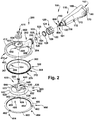
FIG. 2 is a schematic exploded perspective view of the power operated dermatome ofFIG. 1 ; -
Figure 3 is a schematic side elevation view of the power operated dermatome ofFigure 1 ; -
Figure 4 is a schematic top plan view of the power operated dermatome ofFigure 1 ; -
Figure 5 is a schematic bottom plan view of the power operated dermatome ofFigure 1 ; -
Figure 6 is a schematic front elevation view of the power operated dermatome ofFigure 1 ; -
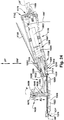
Figure 7 is a schematic longitudinal section view of the power operated dermatome ofFigure 1 , as viewed along a longitudinal axis LA of the handle assembly of the dermatome; -
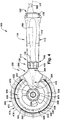
Figure 8 is a schematic top plan view of the head assembly of the power operated dermatome ofFigure 1 , with a gear train of the head assembly removed for clarity; -
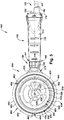
Figure 9 is a schematic rear elevation view of the head assembly ofFigure 8 ; -
Figure 10 is a schematic exploded top perspective view of the head assembly ofFigure 8 ; -
Figure 11 is a schematic exploded bottom perspective view of the head assembly ofFigure 8 , teaching a depth gauge plate according to the present invention; -
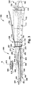
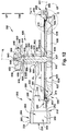
Figure 12 is a schematic section view of the head assembly ofFigure 8 as viewed from a plane indicated by the line 12-12 inFigure 9 ; -
Figure 13 is a schematic enlarged section view of a portion of the head assembly ofFigure 8 that is within a dashed circle labeledFig. 13 inFigure 12 ; -
Figure 14 is a schematic front elevation view of an exemplary embodiment of the rotary knife blade of the power operated dermatome ofFigure 1 ; -
FIG. 15 is a schematic section view of the rotary knife ofFIG. 14 , as seen from a plane indicated by the line 15- 15 inFIG. 14 ; -
FIG. 16 is a schematic enlarged section view of a cutting edge portion of the rotary knife blade shownFIG. 15 that is within a dashed circle labeledFIG. 16 inFIG. 15 ; -
FIG. 17 is a schematic section view of the power operated dermatome ofFIG. 1 , as manipulated to make an initial incision or cut in skin tissue for a thin type, split thickness skin graft wherein a depth of a layer of skin tissue being excised from a patient or donor graft site is on the order of 0.127 mm to 0.305 mm (0.005 in. to 0.012 in.); -
FIG. 18 is a schematic view, partially in perspective and partially in section, of the power operated dermatome ofFIG. 1 , as manipulated to cut or excise a thin type, split thickness skin graft wherein a depth of a layer of skin tissue being excised from a patient or donor graft site is on the order of 0.127 mm to 0.305 mm (0.005 in. to 0.012 in.); -
FIG. 19 is a schematic view, partially in perspective and partially in section, of the power operated dermatome ofFIG. 1 , as manipulated to terminate an incision in a thin type, split thickness skin graft wherein a depth of a layer of skin tissue being excised from a patent or donor graft site is on the order of 0.127 mm to 0.305 mm (0.005 in. to 0.012 in.); -
FIG. 20 is a schematic view, partially in perspective and partially in section, of the power operated dermatome ofFIG. 1 , as used in a full thickness skin graft wherein a depth of a layer of skin tissue being excised from a donor graft site is on the order of 0.762 mm to 1.092 mm (0.030 in. to 0.043 in.); -
FIG. 21 is a schematic section view of a portion of the dermatome ofFIG. 1 showing the depth gauge assembly in a fully closed position providing a minimum depth of cut of the dermatome; and -
FIG. 22 is a schematic perspective view of a second exemplary embodiment of a hand held, power operated dermatome of the present disclosure including a handle assembly and a head assembly including a rotary knife blade and a depth gauge assembly extending into a central, interior region defined by the rotary knife blade; -
Figure 23 is a schematic front elevation view of the power operated dermatome ofFigure 22 ; and -
Figure 24 is a schematic longitudinal section view of the power operated dermatome ofFigure 22 , as viewed along a longitudinal axis LA' of the handle assembly of the dermatome and as seen from a plane indicated by the line 24-24 inFigure 23 . - The present disclosure relates to a hand-held, power operated
dermatome 100 for medical use in removing a layer of skin tissue SK (Figures 17-21 ) from a patient or donor in connection with various medical procedures including split-thickness and full-thickness skin grafting, skin debriding, e.g., removal of burned skin tissue, tumor/lesion removal, breast reduction, among other procedures, including removing a layer of skin tissue from a deceased human or animal donor for skin grafting/transplanting purposes. Advantageously, thedermatome 100 of the present disclosure includes an annularrotary knife blade 300 that is driven about a central axis of rotation R at a high rotational speed (on the order of 500 - 1,500 RPM) by adrive assembly 500 of thedermatome 100 and further includes adepth gauge assembly 600 to allow precise setting and adjustment of a depth of cut DOC of thedermatome 100. - A
cutting edge 360 of therotary knife blade 300 cuts or excises an upper layer of skin tissue SK from a grafting region GR, resulting in an excised section or layer of skin tissue EST, as illustrated inFigures 18-20 . In thedermatome 100 of the present disclosure, a cutting angle CA (Figure7 ,12 ,13 and16 ) of theblade section 304 adjacent thecutting edge 360 with respect to a cutting plane CP of therotary knife blade 300 is relatively shallow. In one exemplary embodiment, the cutting angle CA is approximately 30° with respect to the cutting plane CP. Thedepth gauge assembly 600 of thedermatome 100 includes an axiallyadjustable depth gauge 620. The axiallyadjustable depth gauge 620 includes adepth gauge plate 622 and adepth gauge shaft 640 affixed to thedepth gauge plate 622. Thedepth gauge 620 extends into acentral opening 301 defined by therotary knife blade 300. - An axial position of the
depth gauge plate 622 with respect to thecutting edge 360 of therotary knife blade 300 is determined by a rotation position of adepth adjustment knob 650 of thedepth gauge assembly 600. The axial position of thegauge plate 622 of thedepth gauge 620 with respect to thecutting edge 360 of therotary knife blade 300 sets the depth of cut DOC of thedermatome 100. The depth of cut DOC of thedermatome 100 determines the depth or thickness of a section of skin tissue SK excised by thedermatome 100. The depth or thickness of an excised skin tissue section or layer is labeled as DEST inFigures 18-20 . That is, the depth or thickness of an excised skin tissue section DEST of a patient or donor is determined by the depth of cut DOC of thedermatome 100, as precisely set by the operator of thedermatome 100 using thedepth adjustment knob 650. - As compared to prior manual or power operated dermatomes, the high rotary speed of the
rotary knife blade 300 of thedermatome 100 of the present disclosure, in combination with a shallow cutting angle CA of theknife blade 300 and configuration of thedepth gauge assembly 600 and, specifically, thedepth gauge plate 622, facilitate an operator's ability to cut or harvest an excised layer of skin tissue EST having a desired depth of cut of the excised tissue DEST that is more uniform and consistent along a longitudinal extend LE (Figures 18 and19 ) of the excised skin tissue EST than what would be expected using a prior manual dermatome or a prior power operated dermatome. Thedermatome 100 of the present disclosure advantageously provides for improved control and manipulation of thedermatome 100 by an operator, using one hand, as thedermatome 100 is moved along a path of travel PT to cut the skin tissue SK to produce the excised skin section EST. Moreover, the high rotary speed of therotary knife blade 300 of thedermatome 100 reduces operator fatigue when removing large sections of skin tissue ST in a grafting region GR. The high rotary speed of therotary knife blade 300 also facilitates making an initial incision (FIG. 17 ) in a layer of skin tissue SK at thecutting edge 360 of therotary knife blade 300 without the need for applying counter traction to the skin tissue ST in the grafting region GR. - Advantageously, rotation of the
depth adjustment knob 650 of thedepth gauge assembly 600 quickly and precisely changes the axial position of thedepth gauge plate 622 with respect to the cutting edge of therotary knife blade 300, thereby allowing the operator to change the depth of cut DOC of thedermatome 100, as desired. The depth of cut DOC of thedermatome 100 directly determines the resulting excised skin tissue depth of cut DEST. By way of example and without limitation, thedermatome 100 of the present disclosure may be advantageously used for split thickness skin grafting (schematically depicted inFIGS. 17-19 ) and full thickness skin grafts (schematically depicted inFIG. 20 ). Approximate depth or thickness ranges for split thickness skin grafting may be categorized into three types of split thickness skin grafting: a) thin-type-skin tissue depth range 0.127 mm to 0.305 mm (0.005 in.-0.012 in.); b) intermediate-type-depth range 0.305 mm to 0.457 mm (0.012 in.-0.018 in.); and c) thick-type-depth range 0.457 mm to 0.762 mm (0.018 in-0.030 in.). The approximate depth or thickness range for full thickness skin grafting is 0.762 mm to 1.092 mm (0.030 in.-0.043 in.). - The
dermatome 100 of the present disclosure provides for both rapid and precise adjustment of the dermatome depth of cut DOC and improved control and manipulation of thedermatome 100. These features enhance the ability of an operator to produce an excised skin tissue section EST having a desired depth of excised skin tissue DEST and having a consistent or uniform depth along the longitudinal extent LE of the excised skin tissue section EST, even when undertaking thin-type, split-thickness skin grafts wherein the desired depth or thickness of the excised skin tissue EST is in a range of approximately 0.127 mm to 0.305 mm (0.005 in. to 0.012 in.) in depth (FIGS. 17-19 ). Advantageously, the operator need only keep thecutting edge 360 of thedermatome 100 flush or flat against the skin tissue ST as thedermatome 100 is moved along its path of travel PT to excise a section of skin tissue EST. This makes the cutting procedure less dependent on operator skill level, as opposed to a cutting procedure where the operator was required to maintain a particular angle of the dermatome with respect to the skin tissue as the dermatome is moved along its path of travel or where the operator was required to change the angle of the dermatome with respect to the skin tissue as the dermatome is moved along its path of travel. The characteristics of thedermatome 100 of the present disclosure allow an operator to cut excised skin tissue sections EST of desired depth and substantially uniform depth from a patient/donor grafting region GR with less dependence on operator skill and more dependence on the attributes and characteristics of thedermatome 100. - Moreover, as can be seen in
Figure 5 , because thecutting edge 360 of therotary knife blade 300 of thedermatome 100 extends around the entire 360° circumference of therotary knife blade 300, a cutting region of thedermatome 100 likewise extends 360° around thecutting edge 360. Thus, unlike prior manual or power operated dermatomes having a straight cutting blade and, therefore, were generally limited to a single cutting direction, thedermatome 100 of the present disclosure may advantageously used in any desired cutting direction - toward the operator, away from the operator, parallel to the operator, and any direction therebetween. Thus, thedermatome 100 of the present disclosure can be moved in various directions, as desired by the operator, to cut skin tissue SK from a grafting region GR, including a natural movement of sweeping the operator's hand and arm in a generally arcuate path inwardly toward the operator's body, thereby cutting the skin tissue section ST as thedermatome 100 along a generally arcuate path toward the operator's body. Advantageously, such a "toward the operator" cutting direction of thedermatome 100 facilitates a clear view of the grafting region GR by the operator. Advantageously, the range of cutting directions afforded by thedermatome 100 of the present disclosure facilitates maneuvering of thedermatome 100 around tight spaces and/or boney prominences in the grafting region GR. - A first exemplary embodiment of a hand-held, power operated dermatome of the present disclosure is schematically shown at 100 in
Figures 1-7 . The power operateddermatome 100 includes anelongated handle assembly 110 and ahead assembly 200 extending from a forward ordistal end 160 of thehandle assembly 110. Anattachment assembly 120 releasably affixes thehead assembly 200 to thehandle assembly 110. As is best seen inFigures 8-13 , thehead assembly 200 includes a frame body orframe housing 202, therotary knife blade 300, an annularblade housing assembly 400 which rotatably supports therotary knife blade 300 for rotation about the central axis of rotation R and thedepth gauge assembly 600. Theblade housing assembly 400 includes anannular blade housing 410 and ablade lock ring 450 which is releasably affixed to theblade housing 410 to trap and secure therotary knife blade 300 for rotation with respect to theblade housing assembly 400. As is best seen inFigures 14-16 , therotary knife blade 300 includes abody section 302, ablade section 304 and a continuousrolling bearing structure 370 defining a portion of an outer peripheral surface 369 (Figure 13 ) of therotary knife blade 300. As can best be seen inFigure 17 , the continuousrolling bearing structure 370 is permanently affixed to aconcave bearing surface 319 of the rotary knifeblade body section 302 and, in turn, defines aconvex bearing surface 380 of therotary knife blade 300. - As can be seen schematically in
Figure 7 , therotary knife blade 300 is rotated with respect to theblade housing assembly 400 about the central axis of rotation R by adrive assembly 500 which includes adrive motor assembly 501 and agear train 520. In one exemplary embodiment, thedrive motor assembly 501 is supported by thehandle assembly 110, while thegear train 520 is supported by agearbox housing 203 of theframe body 202 of thehead assembly 200. Thedepth gauge assembly 600 is also supported by theframe body 202 and includes adepth gauge support 602. Thedepth gauge support 602, which extends from theframe body 202, in turn, supports thedepth gauge 620 including thedepth gauge plate 622 anddepth gauge shaft 640. Thedepth gauge 620 extends into the centralinterior region 301 of therotary knife blade 300. - As can best be seen in
Figures 1-5 and7 , thehandle assembly 110 extends between the forward ordistal end 160 and a rearward orproximal end 162 and includes anelongated handle 112 and a proximal orrear handle cover 170. Thehandle assembly 110 establishes and extends along a longitudinal axis LA. The longitudinal axis LA of thehandle assembly 110 establishes a longitudinal axis of thedermatome 100. In one exemplary embodiment, the handle assembly longitudinal axis LA is substantially orthogonal to and intersects the central axis of rotation R of therotary knife blade 300. Anouter surface 113 of thehandle 112 is contoured for easy gripping. Thehandle 112 includes a generally cylindrical,longitudinal throughbore 114 which supports thedrive motor assembly 501 of thedrive assembly 500. A forward orfront end 116 of thehandle 112 includes a radially inwardly steppedportion 118 that serves as an attachment point for theattachment assembly 120. - In one exemplary embodiment, the
drive motor assembly 501 is actuated by a combination of anactuation lever 150 which is pivotally mounted with respect to thehandle 112, alever sensing switch 151, and anactuation switch 152. When theactuation lever 150 is pivoted to an "on" position, generally parallel to theouter surface 113 of thehandle 112, alever sensing switch 151 disposed within the handle throughbore is tripped. Anactuation switch 152 is located on thecover 170 at theproximal end 162 of thehandle assembly 110. When theactuation lever 150 is pivoted to the "on" position and theactuation switch 152 is pressed within five seconds of the tripping of thelever sensing switch 151, thedrive assembly 500 is actuated to rotate therotary knife blade 300. If theactuation switch 152 is not pressed within five seconds of the tripping of thelever sensing switch 151, theactuation lever 150 must be released and again pivoted to the "on" position. Alternately, thedrive motor assembly 501 may be actuated by a foot pedal valve positioned at the feet of the operator affixed to thehandle assembly 110 or a toggle or rocker switch mounted on thehandle assembly 110. - The
handle assembly 110 extends orthogonally in a rearward direction RW (Figure 7 ) away from thehead assembly 200 along the handle axis longitudinal axis LA. The longitudinal axis LA is substantially orthogonal to the blade central axis of rotation R and parallel to the cutting plane CP of therotary knife blade 300. This configuration allows the operator of thedermatome 100 to wield and manipulate thedermatome 100 effectively using one hand. Therear cover 170 of thehandle assembly 110 overlies a proximal end of thehandle 112 and is coupled to an air line orair hose 180 which provides a source of high pressure air to provide motive power to thedrive motor assembly 501. - The
attachment assembly 120 includes acoupling collar 122, aretainer 128 and aninner sleeve 130 that attaches to the inwardly steppedportion 118 at thefront end 116 of thehandle 112. Thecoupling collar 122 includes aninner surface 124 having a threadedportion 126. As can best be seen inFigure 7 , thecoupling collar 122 is rotatably secured to thehandle 112 by theretainer 128 and theinner sleeve 130. In turn, the coupling collar122 threads onto a threadedouter surface 230 of theframe body 202 to releasably secure thehead assembly 200 to theforward end 160 of thehandle assembly 110. Advantageously, theattachment assembly 120 allows for easy coupling and decoupling of thehead assembly 200 from thehandle assembly 110 to facilitate disassembly and sterilization of components of thehead assembly 200 upon completion of a skin grafting or other medical procedure performed with thedermatome 100. - As used herein, axial, upper and lower shall mean movement or a dimension in a direction generally along or parallel to an extent of the central axis of rotation R. Forward or distal shall mean in a direction generally along a direction labeled FW in
Figure 7 , the forward direction FW being generally parallel to or along the longitudinal axis LA. Rearward or proximal shall mean a direction generally along a direction labeled RW (opposite of the forward direction FW) inFigure 7 . - As best seen in
Figure 7 , thedrive assembly 500 includes thedrive motor assembly 501 and thegear train 520. The present disclosure contemplates at least two different drive motor assemblies, an air motor embodiment (schematically shown inFigure 7 ) and a flexible drive shaft embodiment (not shown) to provide motive power to rotate therotary knife blade 300 within theblade housing assembly 400. In one exemplary embodiment, thedrive motor assembly 501 includes a vane-type air orpneumatic motor 502 and a planetarygear reduction unit 504. High pressure air is communicated via anair hose 180 coupled to thecover 170 at theproximal end 162 of thehandle assembly 110 and directed into themotor 502. The air is routed through the motor body and directed against a plurality of vanes to rotate a rotor of themotor 502. The rotor includes anoutput shaft 503 coupled to the planetarygear reduction unit 504. The planetarygear reduction unit 504 serves to convert the high rotational speed of the rotor shaft to adrive coupling 506 that rotates at a lower speed but a higher torque output than therotor shaft 503. - In one exemplary embodiment, the
gear train 520 comprises a pinion gear 522 (Figure 2 ). Aninput shaft 524 at a proximal end of thepinion gear 522 receives thedrive coupling 506 of thedrive motor assembly 501. Thepinion gear 522 includes agear head 526 at its distal end. In one exemplary embodiment, thegear head 526 defines abevel gear 528 including a set ofbevel gear teeth 530. Thepinion gear 522 is supported for rotation in thegearbox housing 203 of theframe body 202 about a pinion gear axis of rotation PGR (Figure 7 ) and is positioned such that the set ofbevel gear teeth 530 of thepinion gear 522 meshes with a mating set ofbevel gear teeth 330 of a drivengear 328 of therotary knife blade 300. Thegear head 526 of thepinion gear 522 engages and drives the driven gear of therotary knife blade 300 to rotate theblade 300 about its axis of rotation R. - As can be seen in
FIG. 7 , the pinion gear axis of rotation PGR is substantially congruent with the handle assembly longitudinal axis LA. As thedrive coupling 506 of thedrive motor assembly 501 rotates thepinion gear 522 within thegearbox housing 203. Rotation of thepinion gear 522, in turn, rotates therotary knife blade 300 about its axis of rotation R. A suitable pneumatic motor/planetary gear reduction unit configuration is disclosedUS 2011/0247220 A1 to Whited et al., filed Mar. 28, 2011 , and entitled Power Operated Rotary Knife With Disposable Blade Support Assembly ("the '207 application"). The '207 application is assigned to the assignee of the present; disclosure. - Alternatively, the
drive motor assembly 501 may comprise an external drive motor, for example, an external brushless DC servo motor, and a flexible shaft drive transmission (not shown). The drive motor assembly rotates a drive shaft of a flexible shaft drive transmission. A portion of the flexible shaft drive transmission extends through thelongitudinal throughbore 114 of theelongated handle 112 of thehandle assembly 110. A suitable DC drive shaft transmission configuration is disclosed inUS 2013/0178296 A1 to Rapp et al., filed Jan. 6, 2012 , and entitled Flex Shaft-Drive Motor Connection For Power Operated Rotary Knife ("the '760 application"). The '760 application is assigned to the assignee of the present disclosure. - Turning to
FIGS. 8-13 , thehead assembly 200 of the power operateddermatome 100 of the present disclosure includes theframe body 202, therotary knife blade 300, the annularblade housing assembly 400, and thedepth gauge assembly 600. In thedermatome 100, both thedepth gauge assembly 600 and theblade housing assembly 400 are supported by and extend from theframe body 202. Thedepth gauge plate 622 of thedepth gauge assembly 600 extends into theinterior region 301 of therotary knife blade 300. Alower edge region 634 of thedepth gauge plate 622, in combination with thecutting edge 360 of therotary knife blade 300, determine the depth of cut DOC of thedermatome 100. - As best seen in
Figures 8-13 , theframe body 202 includes a rearwardhandle attachment portion 204 and aforward interface portion 206. The rearwardhandle attachment portion 204 comprises a generallycylindrical body 205 defining the threadedouter surface 230 of theframe body 202. The threadedouter surface 230 of the frame bodycylindrical body 205 is engaged by theattachment assembly 120 to releasably affix thehead assembly 200 to thehandle assembly 110. - The
frame body 202 includes agearbox housing 203 which rotatably supportsgear train 520 of thedrive assembly 500, specifically, thepinion gear 522. Thegearbox housing 203 includes aninner surface 208 of theframe body 202. Theinner surface 208 defines alongitudinally extending throughbore 209. As seen inFigure 7 , thepinion gear 522 is seated in thethroughbore 209. A front opening 232 (Figures 11 and12 ) of thethroughbore 209 is configured to allow thegear head 526 of thepinion gear 522 to engage the drivengear 328 of therotary knife blade 300. A rear opening 234 (Figures 9 and12 ) of thethroughbore 209 allows entry of thedrive coupling 506 of thedrive motor assembly 501 into the piniongear input shaft 524 when thehead assembly 200 is releasably affixed to thehandle assembly 110. - The
forward interface portion 206 of theframe body 202 includes anupper interface region 220 that extends or transitions between thecylindrical body 205 of the rearwardhandle attachment portion 204 and the centralcylindrical support 602 of thedepth gauge assembly 600. In one exemplary embodiment, theupper interface region 220, when viewed from above in plan view, comprises a generally V-shapedrib 222 wherein the V-shapedrib 222 is widest adjacent to thecylindrical body 205 and tapers or converges in a direction proceeding toward the centralcylindrical support 602, that is, the centralcylindrical support 602 can be viewed as serving as a termination or vertex of therib 222. Thus, the centralcylindrical support 602 of thedepth gauge assembly 600 is attached to and extends from theframe body 202 and, more specifically, thedepth gauge assembly 600 is attached to and extends from theupper interface region 220 of theframe body 202. - Positioned axially below the
upper interface region 220 is alower interface region 210 that extends or transitions between thecylindrical body 205 of the rearwardhandle attachment portion 204 and theannular blade housing 410 of theblade housing assembly 400. In one exemplary embodiment, thelower interface region 210, when viewed from below in plan view, comprised a Y-shapedsupport 212 that includes arms that extend circumferentially about theannular blade housing 410. Thus, theannular blade housing 410 of theblade housing assembly 400 is attached to and extends from theframe body 202 and, more specifically, the lower interfaceregion interface region 220 of theframe body 202. - As can best be seen in
Figures 14-17 , in one exemplary embodiment, the annularrotary knife blade 300 includes aninner wall 365 and anouter wall 366 and a firstupper end 367 and a secondlower end 368. Theinner wall 365 defines the open,interior region 301 of therotary knife blade 300. Therotary knife blade 300 includes theupper body section 302, thelower blade section 304 and the continuousrolling bearing structure 370. The continuousrolling bearing structure 370 forms a portion of a peripheralouter surface 303 of thebody section 302 and defines theconvex bearing surface 380 of therotary knife blade 300. Theupper body section 302 extends between a firstupper end 306 and a secondlower end 308. Theupper end 306 corresponds to and is congruent with the firstupper end 367 of therotary knife blade 300. Aradially extending shoulder 308a between thebody section 302 and theblade section 304 defines the secondlower end 308 of thebody 302. Thebody section 302 includes aninner wall 310 and a radially spaced apartouter wall 312. The firstupper end 306 of thebody section 302 defines the drivengear 328 of therotary knife blade 300. The drivengear 328 comprises the set ofbevel gear teeth 330 that operatively engage and mesh with thebevel gear 528 of thepinion gear 522, as previously discussed, such that rotation of thebevel gear 528 results in rotation of therotary knife blade 300 about its axis of rotation R. - The
body section 302 of therotary knife blade 300 includes abearing surface 319 formed in theouter wall 312 of thebody 302. In one exemplary embodiment, the bearingsurface 319 comprises abearing race 320 that extends radially inwardly into theouter wall 312. Thebearing race 320 includes a generally convexarcuate bearing face 322. The bearingface 322 provides a seating surface for the continuousrolling bearing structure 370 of therotary knife blade 300. The continuousrolling bearing structure 370 defines theconvex bearing surface 380 of therotary knife blade 300 that projects radially outwardly from theouter wall 312 of thebody section 302 of theblade 300 and thereby forms a portion of a peripheralouter surface 303 of thebody section 302 and forms a portion of a peripheralouter surface 369 of therotary knife blade 300. The continuousrolling bearing structure 370 rotationally supports therotary knife blade 300 with respect to theblade housing assembly 400. - The continuous
rolling bearing structure 370 comprises an annularrolling bearing strip 372 that extends continuously 360° around the periphery of theouter wall 312 of thebody section 302 and is disposed in thebearing race 320. The rollingbearing strip 372 includes a plurality of spaced apartball bearings 376 rotatably supported in radially spaced apart pockets of aseparator cage 378. In one exemplary embodiment, the separator cage is flexible and a diameter of theball bearings 376 is approximately 2 mm. Portions of the plurality ofball bearings 376 extend radially outwardly from theouter wall 310 of theblade body section 302 and thus form a part of theouter periphery 303 of thebody section 302. Specific details concerning the structure and configuration of the plurality of spaced apart ball bearings and the flexible separator cage are disclosed inUS 2013/0025139 A1, filed Jul. 25, 2011 to Whited et al. , and entitled Power Operated Rotary Knife ("the '951 application"). The '951 application is assigned to the assignee of the present disclosure. - The rolling
bearing strip 372 is disposed in an annular gap G defined between opposing faces of therotary knife blade 300, theblade housing 410 and ablade lock ring 450 of theblade housing assembly 400, in the region of the rotary knifeblade bearing race 320. Specifically, the plurality ofball bearings 376 of the rollingbearing strip 372 are disposed within anannular passageway 374, which is circular in cross section and defined by the opposing arcuate bearing surfaces 319, 426, 458 of therotary knife blade 300, theblade housing 410 and theblade lock ring 450, respectively. - By virtue of the annular
rolling bearing strip 372 being continuous and disposed within thebearing race 320, thestrip 372 is permanently affixed to and thus is part of theblade 300. However, as the plurality ofball bearings 376 of the rollingbearing strip 372 contact theblade bearing race 320, the rolling bearing may rotate with respect to theblade body 302 and theblade section 304 of theblade 300. Whenrotary knife blade 300 is rotated by thedrive assembly 500 and, specifically, thepinion gear 522, at a specific, desired RPM, theseparator cage 378 also moves or translates in a circle along the annular gap G, although the rotational speed of theseparator cage 378 within the gap G is less than the RPM of therotary knife blade 300. Thus, when the dermatome is in operation, the continuous, annularrolling bearing strip 372 traverses through theannular passageway 374 forming a circle about the knife blade axis of rotation R. Similarly, when thedermatome 100 is in operation, theseparator cage 378, due to its movement or translation along the annular gap G about the knife blade axis of rotation R, can be considered as forming a complete cylinder within the gap G. Additionally, when therotary knife blade 300 is rotated, the plurality ofball bearings 376 both rotate with respect to theseparator cage 378 and also move or translate along theannular passageway 374 about the knife blade axis of rotation R as theseparator cage 378 moves or translates along the annular gap G. A plane passing through the respective centers of the plurality ofball bearings 376 define a rotational plane RP (Figures 13 and15 ) of therotary knife blade 300. The rotational plane RP of therotary knife blade 300 is substantially parallel to the cutting plane CP of theblade 300 and substantially orthogonal to the axis of rotation R of theblade 300. - The
rotary knife blade 300 also includes theblade section 304 extending between a first upper end 350 (adjacent theshoulder 308a of the body section 302) and a secondlower end 352. The secondlower end 352 corresponds to and is congruent with thelower end 368 of therotary knife blade 300. The blade section includes aninner wall 354 and a radially spaced apartouter wall 356. The inner andouter walls cutting edge 360 of the blade. Thecutting edge 360 of therotary knife blade 300 is generally circular. Theinner wall 310 of thebody section 302 and theinner wall 354 of theblade section 304 combine to form theinner wall 365 of therotary knife blade 300 and define theinterior region 301 of theblade 300. Theinterior region 301 of the rotary knife blade is generally frustoconical, converging in a direction toward thecutting edge 360 of theblade 300. A plane aligned with the generallycircular cutting edge 360 of therotary knife blade 300 defines the cutting plane CP (Figure 15 ) of theblade 300. - In one exemplary embodiment, the
blade section 304 includes anupper region 358 and alower region 359 separated by a knee or discontinuity between the two regions. Of course, it should be recognized that theblade section 304 may comprise a single region with no discontinuity. Thelower region 359 defines the cutting angle CA of the blade and is defined by an angle between theinner wall 354 in thelower region 359 of theblade section 304 and the cutting plane CP. In one exemplary embodiment, the cutting angle CA is approximately 30°, although it should be understood that the cutting angle CA could be greater or smaller. As can be best seen inFIG. 16 , thelower end 352 of theblade section 304 which defines thecutting edge 360, includes a short section ofwall 362 bridging the inner andouter walls cutting edge 360 is formed at the intersection of the short section ofwall 362 and theinner wall 354. The short section ofwall 362 is slightly angled with respect to the cutting plane CP, at about 5° in one exemplary embodiment, to provide relief for thecutting edge 360. - In one exemplary embodiment, the inner diameter (defined by the cutting edge 360) of the
rotary knife blade 300 is approximately 101.6 mm (4.000 in.), while the outer diameter (defined by the outer periphery of the plurality ofball bearings 376 the rollingbearing strip 372 is approximately 131.8 mm (5.189 in.), although it should be understood that the diameters could be larger or smaller. - As can best be seen in
FIGS. 10-13 and16- 17 , theblade housing assembly 400 includes theannular blade housing 410 and theblade lock ring 450. Theannular blade housing 410 extends from and is supported by the Y-shapedsupport 212 of thelower interface region 210 of theforward interface portion 206 of theframe body 202. Theblade housing 410 includes a firstupper end 412 and an axially spaced apart secondlower end 414. Theblade housing 410 further includes aninner wall 416 and a radially spaced apartouter wall 418. Theblade housing 410 includes three peripherally spaced apart threadedopenings 430 of theblade housing 410. The three threadedopenings 430 extend from the secondlower end 414 through the firstupper end 412. Theinner wall 416 of theblade housing 410 includes abearing surface 420. In one exemplary embodiment, the bearingsurface 420 comprises abearing race 422 that extends radially inwardly into theinner wall 416 of theblade housing 410. Thebearing race 422 includes the concave, arcuate bearing surface orface 426. - As can be best be seen in
FIGS. 13 ,17 and18 , in axial extent, thearcuate bearing face 426 is a curved bearing surface that extends from anupper region 376a of theball bearing 376 and generally conforms to the curvature of theball bearing 376 to about amidpoint 376b of theball bearing 376. Thearcuate bearing face 426 does not, however, extend all the way to alower region 376c of theball bearing 376. Instead, an arcuate bearing surface or face 458 formed on aninner surface 456 of theblade lock ring 450 constitutes a portion of a total bearing race 470 (Figures 17 and18 ) provided by theblade housing assembly 400. Thetotal bearing race 470 defined by theblade housing assembly 400 results from a combination of the bearing surfaces of theblade housing 410 and theblade lock ring 450, specifically, the arcuate bearing face 426 of theblade housing 410 and the arcuate bearing face 458 of theblade lock ring 450. Thetotal bearing race 470 serves as an arcuate bearing surface for the annularrolling bearing strip 372 of therotary knife blade 300 when theblade lock ring 450 is secured to theblade housing 410 and therotary knife blade 300 is captured or sandwiched therebetween. - The
blade lock ring 450 includes anupper surface 451 and alower surface 452 and comprises anupper seating region 453 and a radially inwardly offsetlower bearing region 454. Theupper seating region 453 seats flush against theblade housing 410 and includes three peripherally spaced apartslots 462 in anouter periphery 460 of theblade lock ring 450. Theblade lock ring 450 adapted to be secured to a stepped shoulder 415 (Figure 18 ) near thelower end 414 of theblade housing 410. Theblade lock ring 450 is secured to the steppedshoulder 415 of theblade housing 410 via three threadedfasteners 464 that pass through three peripherally spaced apartslots 462 in anouter periphery 460 of theblade lock ring 450. - To install or affix the
rotary knife blade 300 to theblade housing assembly 400, with the blade lock ring removed, thehead assembly 200 is turned upside down and therotary knife blade 300 is placed in the upside downblade housing 410. The plurality ofball bearings 376 of therotary knife blade 300 rest on thebearing race 422 of theblade housing 410 thereby therotary knife blade 300 is supported by theblade housing 410. The threeslots 462 of theblade lock ring 450 are aligned with the threadedopenings 430 of theblade housing 410. The three threadedfasteners 464 pass through theslots 462 and are threaded into the threadedopenings 430 of theblade housing 410 to complete the installation. Because of the configuration of the threeslots 462, it is only necessary to loosen the three threaded fasteners 464 a sufficient amount to rotate theblade lock ring 450 with respect to theblade housing 410. This allows theblade lock ring 450 to be removed from theblade housing 410 without removing the three threadedfasteners 464 from the threadedopenings 430 of theblade housing 410. When theblade lock ring 450 is removed from theblade housing 410 turning thehead assembly 200 upside down causes therotary knife blade 300 to fall out of theblade housing 410 thereby removing theblade 300 from theblade housing assembly 400. - As can best be seen in
FIGS. 10-13 and17- 21 , thedepth gauge assembly 600 includes thedepth gauge support 602 and thedepth gauge 620. Thedepth gauge 620 includes thedepth gauge shaft 640 and thedepth gauge plate 622. Thedepth gauge assembly 600 further includes thedepth adjustment knob 650, astop ring 670, a biasingspring 680 and a dowel pin 690 (FIGS. 10 and11 ). Advantageously, thedepth gauge assembly 600 permits an operator to quickly and accurately change the depth of cut DOC of the dermatome from essentially 0 mm (0.000 in.) (no depth of cut of skin tissue ST-shown schematically inFIGS. 21 ) to 1.143 mm (0.045 in.) (full depth of cut of skin tissue ST-shown schematically inFIGS. 12 and20 ). Obviously, the range of depth of cut DOC may be changed based on the configuration of thedepth gauge assembly 600 and the present disclosure is not limited to the exemplary depth of cut range set forth herein. As changing the depth of cut DOC of thedermatome 100 is accomplished by rotation of thedepth adjustment knob 650, the depth of cut DOC is infinitely variable between the 0 mm (0.000 in.) and 1.143 mm (0.045 in.) endpoints. That is, the operator can precisely dial in an exact desired depth of cut DOC for thedermatome 100. - As best seen in
FIGS. 8 and10- 12 , the depth gaugecylindrical support 602 extends from and is supported by the V-shapedrib 222 of theupper interface region 220 of theforward interface portion 206 of theframe body 202. Thedepth gauge support 602, in one exemplary embodiment, is generally cylindrical and includes anupper end 604 and an axially spaced apartlower end 606. The depth gaugecylindrical support 602 defines an axially extending central opening 608 (FIG. 12 ) passing through thesupport 602. A radially outwardly extendingflange 610 is disposed at theupper end 604 of the depth gaugecylindrical support 602. As can be seen inFIG. 10 , theflange 610 includes a firstsmaller opening 612 that is axially aligned with thecentral opening 608 and a secondlarger opening 614 that is connected to but offset from the firstsmaller opening 612. A radially outwardly extending slot 616 (FIG. 12 ) is disposed between theflange 610 and thecentral opening 608 of the depth gaugecylindrical support 602. - An
upper surface 618 of theflange 610 includes indicia or markings 619 (FIG. 10 ) representing gradations for the depth of cut DOC of thedermatome 100 as thedepth adjustment knob 650 is rotated. Specifically, each of the smaller gradations represent a change in the set depth of cut DOC of 0.0254 mm (0.001 in.), while the larger gradations represent a change in the set depth of cut of 0.127 mm (0.005 in.) Theindicia 619 facilitate precise setting of the dermatome depth of cut DOC by the operator. - The
depth gauge shaft 640 is received in the axially extendingcentral opening 608 of thecylindrical support 602. Thedepth gauge shaft 640 is supported by thecylindrical support 602 for axial movement with respect to thecylindrical support 602. Specifically, thecylindrical support 640 contacts and supports thedepth gauge shaft 640 over an axial length labeled AL inFIG. 12 . In one exemplary embodiment, the axial length AL of thecylindrical support 602 is approximately 26.67 mm (1.05 in.), while the overall axial length of thecylindrical support 602 extending between theupper end 604 of thecylindrical support 602 and thelower end 606 of thecylindrical support 602 is approximately 31.75 mm (1.25 in.). - The
depth gauge 620 is supported by thedepth gauge support 602 and includes thedepth gauge plate 622 and thedepth gauge shaft 640. As can be seen inFIG. 12 , thedepth gauge shaft 640 and thedepth gauge plate 622 are substantially concentric with the knife blade axis of rotation R. Thedepth gauge 620 is adjustable to move axially along the axis of rotation R, that is, the depth gauge moves axially respect to thedepth gauge support 602 and with respect to the cutting plane CP of therotary knife blade 300. Movement of thedepth gauge plate 622 with respect to the cutting plane CP of therotary knife blade 300 changes the dermatome depth of cut DOC. Thedepth gauge plate 622 and a portion of thedepth gauge shaft 640 extend into theinterior region 301 of therotary knife blade 300. Thedepth gauge 620 also includes thestop ring 670 which is affixed to an upper end of thedepth gauge shaft 640 and moves with theshaft 640 axially to limit downward movement of thedepth gauge 620. That is, thestop ring 670 insures that the minimum depth of cut DOC is 0 mm (0.000 in.), as opposed to thedepth gauge plate 622 moving in a downward direction DW to a negative depth of cut DOC position. - The
depth gauge plate 622 is generally disc-shaped and includes anupper surface 623 and an axially spaced apart generally planarlower surface 624. Thedepth gauge plate 622 includes acentral body 626 and a radially outwardly spacedannular rim 628. Thecentral body 626 and theannular rim 628 are connected by three radially extendingribs 630. Thecentral body 626 of thedepth gauge plate 622 includes acentral opening 627 that receives a lower connectingend 642 of thedepth gauge shaft 640 to secure thedepth gauge plate 622 to thedepth gauge shaft 640. - The
depth gauge plate 622 includes a radially outerperipheral surface 632. Alower edge region 634 of thedepth gauge plate 622 is an intersection region between the planarlower surface 624 ofdepth gauge plate 622 and outerperipheral surface 632 of depth gauge plate. At any axial position of thedepth gauge plate 622, thelower edge region 634 of thedepth gauge plate 622 is the closest portion of thedepth gauge 622 to thecutting edge 360 of therotary knife blade 300. Thelower edge region 634 is nearly (but not exactly) axially aligned with the rotary knifeblade cutting edge 360. As such, an axial distance between thelower edge region 634 of thedepth gauge plate 622 and thecutting edge 360 of therotary knife blade 300 determines the depth of cut DOC of thedermatome 100. Recall that thecutting edge 360 defines the cutting plane CP of therotary knife blade 300, therefore, stated another way, an axial distance AD (Figure 18 ) between thelower edge region 634 of thedepth gauge plate 622 and the cutting plane CP of therotary knife blade 300 determines the depth of cut DOC of thedermatome 100. - As best seen in
Figure 12 , thedepth gauge shaft 640 is generally cylindrical and includes the lower connectingend 642 that is received in thecentral opening 627 of thecentral body 626 of thedepth gauge plate 622 to attach thedepth gauge shaft 640 and thedepth gauge plate 622. Thedepth gauge shaft 640 includes a reduced diameter threadedupper portion 643. When thedepth gauge shaft 640 is inserted into the axially extendingcentral opening 608 of thedepth gauge support 602, first, the second threadedportion 648 of thedepth gauge shaft 640 is threaded into the central threadedopening 656 of thedepth adjustment knob 650, then, thestop ring 670 is threaded onto the upper threadedportion 643 of thedepth gauge shaft 640 to secure the depth gauge shaft 640 (and attached depth gauge plate 622) to thedepth gauge support 602. When it is desired to remove thedepth gauge shaft 640 from thedepth gauge support 602, thestop ring 670 is unthreaded and removed from thedepth gauge shaft 640 and thedepth gauge shaft 640 is unthreaded from the central threadedopening 656 of thedepth adjustment knob 650, allowing thedepth gauge shaft 640 to drop out of thedepth gauge support 602 for cleaning/sterilization purposes. - The
depth gauge shaft 640 includes anouter surface 647 defining anaxially extending slot 646. Theaxially extending slot 646 receives the dowel pin 690 (figures 10 and11 ) that passes through aradial opening 617 in the depth gaugecylindrical support 602 to prevent relative rotation between thedepth gauge shaft 640 as supported within thecylindrical support 602. Thedepth gauge shaft 640 also includes a second threadedportion 648 that is disposed below the threadedupper portion 643. The second threadedportion 648 of thedepth gauge shaft 640 is threadedly received in a threadedcentral opening 656 of thedepth adjustment knob 650. - The
depth adjustment knob 650 includes anupper end 652 and alower end 654. Thedepth adjustment knob 650 includes a central threadedopening 656 which is threaded onto the second threadedportion 648 of thedepth gauge shaft 640 and, in combination with the dowel pin 690 - axially extendingslot 646 interfit, allows thedepth adjustment knob 650, when rotated, to drive thedepth gauge shaft 656 upward or downward with respect to the depth gaugecylindrical support 602. - The
depth adjustment knob 650 includes acentral stem 660 and an enlargedupper head 658 above thestem 660 and an enlargedlower head 664 below thestem 660. The enlargedlower head 664 is sized to pass though the larger offsetopening 614 of theflange 610 of the depth gaugecylindrical support 602 and is received in theslot 616 of thecylindrical support 602 to restrain axial movement between thedepth adjustment knob 650 and thecylindrical support 602. The enlargedupper head 658 of thedepth adjustment knob 650 includes a recessedcontact surface 666 that is configured to be contacted by alower surface 674 of thestop ring 670. An upper surface of the enlargedupper head 658 will include an arrow or some other marking that can be aligned with theindicia 619 marked on the upper surface w618 of thecylindrical support flange 610 to aid the operator in adjusting and setting the depth of cut DOC of thedermatome 100. - As the
depth adjustment knob 650 is rotated by the operator, thedowel pin 690 extending into theaxially extending slot 646 prohibits thedepth gauge shaft 640 and thedepth gauge plate 622 from rotating with thedepth adjustment knob 650. The dowel pin/axially extendingslot configuration 690/646 does permit thedepth gauge shaft 640 to move up and down axially within the depth gaugecylindrical support 602 to change the depth of cut DOC of thedermatome 100. However, thedepth gauge shaft 640 is constrained from rotating with thedepth adjustment knob 650 by virtue of thedowel pin 690 fitting into theaxially extending slot 646. Since thedepth gauge shaft 640 is constrained from rotating with thedepth adjustment knob 650 and theknob 650 is constrained from axial movement by virtue of the enlargedlower head 664 of theknob 664 being confined in the radially outwardly extendingslot 616 of the depth gaugecylindrical support 602. Thus, rotation of thedepth adjustment knob 650 drives thedepth gauge shaft 640 axially in the upward direction UP or the downward direction DW with respect to the depth gauge cylindrical support, depending on the direction of rotation of thedepth adjustment knob 640. - When
depth adjustment knob 650 is rotated to move thedepth gauge 620 in the downward direction DW, thedowel pin 690 prevents rotation of thedepth gauge 620 with thedepth adjustment knob 650. Thus, depending on the direction of rotation of thedepth adjustment knob 650, thedepth gauge 620 will be moved in the upward direction UP or the downward direction DW with respect to thecylindrical support 602 and therotary knife blade 300. Movement of thedepth gauge 620 in the upward direction is limited by contact between theupper surface 645 of thecentral portion 644 of thedepth shaft 640 and alower end 654 of thedepth adjustment knob 650 such that a maximum depth of cut DOC is 1.143 mm (0.045 in.). This maximum depth of cut DOC configuration is shown inFIGS. 12 and13 and is referred to as the fully open position of thedermatome 100. - Movement of the depth gauge in the downward direction DW is limited by contact between the
lower surface 674 of thestop ring 670 and the recessedcontact surface 666 of the enlargedupper head 658 of thedepth adjustment knob 650. This minimum depth of cut DOC configuration is shown inFIG. 21 and is referred to as the fully closed position of thedermatome 100. The biasingspring 680 is trapped between thecentral body 626 of thedepth gauge plate 622 and thelower end 606 of the depth gaugecylindrical support 602 to bias thedepth gauge 620 to the fully closed position. - In one exemplary embodiment, the
handle assembly 110 may be fabricated of plastic or other material or materials known to have comparable properties and may be formed by molding and/or machining Theattachment assembly 120, theframe body 202, and thedepth gauge assembly 600 may be fabricated of aluminum or stainless steel or other material or materials known to have comparable properties and may be formed/shaped by casting and/or machining Therotary knife blade 300 and theblade housing assembly 400 may be fabricated of a hardenable grade of alloy steel or a hardenable grade of stainless steel, or other material or materials known to have comparable properties and may be formed/shaped by machining, forming, casting, forging, extrusion, metal injection molding, and/or electrical discharge machining or another suitable process or combination of processes. -
FIGS. 17-19 schematically illustrate use of thedermatome 100 of the present disclosure for excising a layer skin tissue ST in a donor grafting region GR and, in particular, obtaining a thin type, split thickness skin graft wherein a depth of a layer of skin tissue being excised from the graft region GR is on the order of 0.127 mm to 0.305 mm (0.005 in. to 0.012 in.)FIG. 17 schematically shows the initial incision into an upper layer or surface SST of the skin tissue ST with thedermatome 100. Recall that the cutting angle CA of therotary knife blade 300 is approximately 30°. In making the incision into the skin tissue surface SST, the angle of thedermatome 100 is manipulated such that a skin tissue cutting angle STCA is shallower than the cutting angle CA of theknife blade 300. In one exemplary embodiment, the cutting angle of theinner wall 310 in thelower region 359 of theblade section 304 adjacent thecutting edge 360 with respect to the surface SST of the skin tissue ST being excised lower is approximately 15°. Thus, the skin tissue cutting angle STCA (approximately 15°) is less than the blade cutting angle CA. (approximately 30°). Thus, theouter wall 418 of theblade housing 410 is not vertical, but rather slightly angled downwardly toward the skin tissue ST. -
Figure 18 schematically shows the cutting or excising of the skin tissue ST. As the actuateddermatome 100 moves along a path of travel PT, thedermatome 100 produces an excised section of skin tissue EST which flows along theinner wall 365 and through the centralinterior region 301 of therotary knife blade 300, as depicted. A longitudinal extent LE of the excised section EST, a depth or thickness of excised skin tissue DEST should be uniform and should conform in thickness to the depth of cut DOC set by the operator of thedermatome 100. In moving along the path of travel PT, the angle of thedermatome 100 is held relatively flat, that is, the skin tissue cutting angle STCA is approximately equal to the rotary knife blade cutting angle CA. The skin tissue cutting angle STCA and the rotary knife blade cutting angle CA both being approximately 30°. Advantageously, the operator need only keep the cutting plane CP of thedermatome 100 flush or flat against the surface SST of the skin tissue ST as thedermatome 100 is moved along its path of travel PT to excise a section of skin tissue EST. Thus, with thedermatome 100 of the present disclosure, undertaking a successful excising procedure which results in an excised skin tissue section EST having a consistent and desired depth or thickness is more straightforward and less dependent on operator skill level. -
FIG. 19 schematically shows the termination of the excising procedure, that is, ending of the cutting of the skin tissue ST in the grafting region GR with thedermatome 100. Like with the incision, thedermatome 100 is manipulated by the operator to have a shallower skin tissue cutting angle STCA of approximately 15°. This shallow skin tissue cutting angle STCA causes theblade 300 to tend to move upwardly through the skin tissue SK. If necessary, the operator can slightly wiggle thedermatome 100 in a side-to-side motion to facilitate the rotary knife blade in cutting upwardly and through the surface of the skin tissue ST. When theblade 300 comes through or emerges from the surface SST of the skin tissue ST, this terminates the cut or excision and determines or fixes the total longitudinal extent LE of the excised skin tissue section EST. -
FIG. 20 schematically depicts the excising of a thicker layer of skin tissue ST with thedermatome 100. Here, thedermatome 100 is used for obtaining a full thickness skin graft from a donor graft region GR wherein a depth of a layer DEST of skin tissue EST being excised from a donor graft region GR is on the order of 0.762 mm to 1.092 mm (0.030 in. to 0.043 in.). - A second exemplary embodiment of a hand-held, power operated dermatome of the present disclosure is schematically shown at 1000 in
FIGS. 22-24 . The power operateddermatome 1000 is similar in configuration and operation to the power operateddermatome 100, as described above, and the description of thedermatome 100, as set forth above, is referenced and incorporated herein with respect to thedermatome 1000. - The power operated dermatome includes an
elongated handle assembly 1110, similar to thehandle assembly 110, and ahead assembly 1200, similar to thehead assembly 200, extending from a forward ordistal end 1160 of thehandle assembly 1110. Thehandle assembly 1110 includes ahandle 1112 and anactuation lever 1150 and extends between thedistal end 1160 adjacent thehead assembly 1200 and aproximal end 1162. Acover 1170 at theproximal end 1162 of thehandle assembly 1110 is coupled to anair hose 1180 which provides motive power to thedrive assembly 1500, similar to thedrive assembly 500, of thedermatome 1000. Anattachment assembly 1120, similar to theattachment assembly 120, releasably affixes thehead assembly 1200 to thehandle assembly 1110. - The
dermatome 1000 includes thedrive assembly 1500, similar to thedrive assembly 500, including adrive motor assembly 1501, similar to thedrive motor assembly 501, and agear train 1520, similar to thegear train 520. Thegear train 1520, in one exemplary embodiment, comprises apinion gear 1522, similar to thepinion gear 522. - The
head assembly 1200 includes a frame body orframe housing 1202, similar to theframe body 202, arotary knife blade 1300, similar to therotary knife blade 300, ablade housing assembly 1400, including ablade housing 1410 and ablade lock ring 1450, similar to theblade housing assembly 400, and adepth gauge assembly 1600, similar to thedepth gauge assembly 600. Theframe body 1202 includes a rearwardhandle attachment portion 1204 comprising acylindrical body 1205 and aforward interface portion 1206. Theframe body 1202 includes agearbox housing 1203 defined by athroughbore 1209 through theframe body 1202. Thegear train 1520 is supported within thegearbox housing 1203. Theforward interface portion 1206 of theframe body 1202 includes alower interface region 1210 that extends or transitions between the rearwardhandle attachment portion 1204 and theannular blade housing 1410 of theblade housing assembly 1400. Thelower interface region 1210 includes a generally Y-shapedsupport 1212. Theforward interface portion 1206 of theframe body 1202 also includes anupper interface region 1220 that extends or transitions between the rearwardhandle attachment portion 1204 and a centralcylindrical support 1602 of thedepth gauge assembly 1600. Theupper interface region 1220 includes a generally V-shapedrib 1222 that converges proceeding toward and has a vertex generally at the centralcylindrical support 1602. - The
depth gauge assembly 1600 includes the depth gauge centralcylindrical support 1602, similar to the centralcylindrical support 602, that extends from the V-shapedrib 1222 of theupper interface region 1220 of theforward interface portion 1206 of theframe body 1202. Thedepth gauge assembly 1600 also includes adepth gauge 1620, similar to thedepth gauge 620. Thedepth gauge 1620 includes thedepth gauge shaft 1640 and adepth gauge plate 1622. Thedepth gauge assembly 1600 further includes adepth adjustment knob 1650 and astop ring 1670, similar to thedepth adjustment knob 650 and stopring 670. - The
rotary knife blade 1300 is supported for rotation about an axis of rotation R', similar to the axis of rotation R, by theblade housing assembly 1400. Therotary knife blade 1300 includes acutting edge 1360 which defines a cutting plane CP', similar to the cutting plane CP, and further includes a continuousrolling bearing structure 1370, similar to the continuousrolling bearing structure 370, which defines a rotational plane RP' of theblade 1300, similar to the rotational plane RP of theblade 300. Theblade housing assembly 1400 includes anannular blade housing 1410, similar to theblade housing 400, and ablade lock ring 450, similar to theblade lock ring 1450, which is releasably affixed to theblade housing 1410 to trap and secure therotary knife blade 1300 for rotation with respect to theblade housing assembly 1400. - As can best be seen in
Figure 24 , thehandle assembly 1110 extends along a longitudinal axis LA' which is canted or angled upwardly at a handle angle HA' with respect to the cutting plane CP' and the rotational plane RP' of therotary knife blade 1300 and with respect to the planarlower surface 1624 of thedepth gauge plate 1622. That is, aproximal end 1162 of thehandle assembly 1110 is spaced higher in an upward direction UP' above the cutting plane CP' of therotary knife blade 1300 or the planarlower surface 1624 of thedepth gauge plate 1622 than is thedistal end 1160 of thehandle assembly 1110. In thedermatome 100, the handle angle was substantially 0°. In one exemplary embodiment of thedermatome 1000, the handle angle HA' with respect to the cutting plane CP' or the rotational plane RP' of the rotary knife blade is in a range of 10°-20° and, more particularly, in one exemplary embodiment, the handle angle HA' may be approximately 15°. The handle angle HA' advantageously provides for ease of operation and clearance for the fingers of the operator. Recall that with thedermatomes dermatome 1000 flush or flat against the surface SST of the skin tissue ST as thedermatome 1000 is moved along its path of travel PT. The upward angle HA' of thehandle assembly 1110 of thedermatome 1000 facilitates keeping the cutting plane CP' of the dermatomehead assembly 1200 flush or flat against the surface SST of the skin tissue ST during an excising procedure. - The rearward
handle attachment portion 1204 of theframe body 1202 of thedermatome 1000 is slightly different than the corresponding rearward handleattachment portion 204 of theframe body 202 of thedermatome 100. To match the upward canted or tilted handle angle HA' of the handle assembly 1100, the rearward handleattachment portion 1204 is also angled upwardly to match the handle angle of the handle assembly 1100. This can best be seen inFIG. 24 . Similarly, thegear train 1520 of thehead assembly 1200 is modified accordingly to account for the different angle of contact between thepinion gear 1522 and the set of gear teeth of therotary knife blade 1300. - Another difference between the
dermatomes depth gauge plate 1622, in thedermatome 1000, an axial length AL' was increased slightly. Recall that the axial length AL of thecylindrical support 602 of thedermatome 100, in one exemplary embodiment, was approximately 26.67 mm (1.05 in.), while the overall axial length of thecylindrical support 602 extending between theupper end 604 of thecylindrical support 602 and thelower end 606 of thecylindrical support 602 was approximately 31.75 mm (1.25 in.). In one exemplary embodiment of thedermatome 100, the axial length AL' of the cylindrical support is approximately 33.02 mm (1.30 in.), while the overall axial length of thecylindrical support 1602 between the upper and lower ends is approximately 38.1 mm (1.50 in.). - As used herein, terms of orientation and/or direction such as front, rear, forward, rearward, distal, proximal, distally, proximally, upper, lower, inward, outward, inwardly, outwardly, horizontal, horizontally, vertical, vertically, axial, radial, longitudinal, axially, radially, longitudinally, etc., are provided for convenience purposes and relate generally to the orientation shown in the Figures and/or discussed in the Detailed Description. Such orientation/direction terms are not intended to limit the scope of the present disclosure, this application, and/or any of the claims appended hereto. Further, as used herein, the terms comprise, comprises, and comprising are taken to specify the presence of stated features, elements, integers, steps or components, but do not preclude the presence or addition of one or more other features, elements, integers, steps or components.
Claims (12)
- A head assembly (200) for a power operated dermatome (100), the head assembly (200) comprising:a frame body (202),a blade housing assembly (400),an annular rotary knife blade (300) supported for rotation about an axis of rotation (R) by the blade housing assembly (400), the rotary knife blade (300) including an inner wall (365) defining an interior region (301) of the rotary knife blade (300) and having a cutting edge (360) at one end (368) of the rotary knife blade (300) defining a cutting plane (CP) orthogonal to the axis of rotation (R) of the rotary knife blade (300), anda depth gauge assembly (600) including a depth gauge support (602) and a depth gauge (620) including a depth gauge shaft (640) and a depth gauge plate (622) extending radially outwardly from the depth gauge shaft (640), the depth gauge shaft (640) supported by the depth gauge support (602) for axial movement of the depth gauge (620) along the axis of rotation (R) of the rotary knife blade (300), the depth gauge shaft (640) being concentric with the axis of rotation (R) of the rotary knife blade, the depth gauge plate (622) extending into the interior region (301) of the rotary knife blade (300) and the depth gauge support (602) attached to and extending from the frame body (202),wherein the depth gauge plate (622) is disk-shaped,characterized in thatthe depth gauge plate (622) includes an annular rim (628) having a planar lower surface (624).
- The head assembly (200) of claim 1 wherein the rotary knife blade (300) includes an annular continuous rolling bearing strip (372) which supports the rotary knife blade (300) for rotation with respect to the blade housing assembly (400) and defines a portion of an outer peripheral surface of the rotary knife blade (300), the annular continuous rolling bearing strip (372) comprising a plurality of rolling bearings (376) rotatably supported in spaced apart relation in a flexible separator cage (378).
- The head assembly (200) of claim 2 wherein the annular continuous rolling bearing strip (372) is seated in a bearing race (320) formed in an outer wall of a body section of the rotary knife blade (300).
- The head assembly (200) of any one of claims 1 to 3 wherein the depth gauge plate (622) includes an outer peripheral surface (632), the planar lower surface (624) and the outer peripheral surface (632) defining a lower edge region (634), an axial distance between the lower edge region (634) and the cutting plane (CP) of the rotary knife blade (300) determining a depth of cut of the head assembly (200).
- The head assembly (200) of any one of claims 1 to 4 wherein the depth gauge assembly (600) further includes a depth adjustment knob (650) supported by the depth gauge support (602), rotation of the depth adjustment knob (650) changing an axial position of the depth gauge plate (622).
- The head assembly (200) of any one of claims 1 to 5 wherein the depth gauge support (602) is attached to and extends from an upper interface region (220) of the frame body (202), the upper interface region (220) comprising a V-shaped rib (222) converging toward the depth gauge support (602).
- The head assembly (200) of any one of claims 1 to 6 wherein the blade housing assembly (400) includes an annular blade housing (410) and a blade lock ring (450) removably attached to the annular blade housing (410) to secure the rotary knife blade (300) to the blade housing assembly (400).
- The head assembly (200) of claim 7 wherein the annular blade housing (410) is attached to and extends from the frame body (202).
- The head assembly (200) of claim 7 wherein the blade housing assembly (400) includes a bearing race (470) that is engaged by a continuous rolling bearing structure of the rotary knife blade (300) to rotatably support the rotary knife blade (300) with respect to the blade housing assembly (400), the bearing race (470) of the blade housing assembly (400) comprising a first bearing surface (420) defined by an inner wall (416) of the annular blade housing (410) and a second bearing surface (458) defined by an inner wall (456) of the blade lock ring (450).
- The head assembly (200) of any one of claims 1 to 9 wherein a gear train (520) is supported in a throughbore of the frame body (202).
- The head assembly (200) of any one of claims 1 to 10 wherein the frame body (202) includes a rearward handle attachment portion (204) that is angled upwardly with respect to the cutting plane (CP) of the rotary knife blade (300).
- A power operated dermatome (100) comprising:a handle assembly (110), anda head assembly (200) according to any one of claims 1 to 11 removably coupled to the handle assembly (110).
Applications Claiming Priority (2)
| Application Number | Priority Date | Filing Date | Title |
|---|---|---|---|
| US13/606,836 US9592076B2 (en) | 2012-09-07 | 2012-09-07 | Power operated dermatome with rotary knife blade |
| PCT/US2013/058133 WO2014039601A1 (en) | 2012-09-07 | 2013-09-05 | Power operated dermatome with rotary knife blade |
Publications (3)
| Publication Number | Publication Date |
|---|---|
| EP2892699A1 EP2892699A1 (en) | 2015-07-15 |
| EP2892699A4 EP2892699A4 (en) | 2016-05-25 |
| EP2892699B1 true EP2892699B1 (en) | 2020-04-01 |
Family
ID=50234065
Family Applications (1)
| Application Number | Title | Priority Date | Filing Date |
|---|---|---|---|
| EP13835651.4A Active EP2892699B1 (en) | 2012-09-07 | 2013-09-05 | Power operated dermatome with rotary knife blade |
Country Status (6)
| Country | Link |
|---|---|
| US (1) | US9592076B2 (en) |
| EP (1) | EP2892699B1 (en) |
| AU (1) | AU2013312723B2 (en) |
| BR (1) | BR112015005025B1 (en) |
| CA (1) | CA2883924C (en) |
| WO (1) | WO2014039601A1 (en) |
Families Citing this family (32)
| Publication number | Priority date | Publication date | Assignee | Title |
|---|---|---|---|---|
| US6769184B1 (en) * | 1998-07-22 | 2004-08-03 | Bettcher Industries, Inc. | Low friction rotary knife |
| US10022146B2 (en) | 2015-05-29 | 2018-07-17 | Exsurco Medical, Inc. | Power operated rotary excision tool |
| USD907205S1 (en) | 2012-09-07 | 2021-01-05 | Exsurco Medical, Inc. | Power operated rotary excision tool |
| US10039567B2 (en) | 2012-09-07 | 2018-08-07 | Exsurco Medical, Inc. | Power operated dermatome with shielded rotary knife blade |
| US10537356B2 (en) | 2014-06-16 | 2020-01-21 | Exsurco Medical, Inc. | Power operated rotary excision tool |
| US9877743B2 (en) * | 2013-01-17 | 2018-01-30 | Natural Nipple Knife Llc | Circular surgical scalpel and marker |
| WO2015164527A1 (en) * | 2014-04-22 | 2015-10-29 | Hantover, Inc. | Rotary knife blade with double beveled inside surface |
| WO2016172544A1 (en) * | 2015-04-24 | 2016-10-27 | The Regents Of The University Of Colorado, A Body Corporate | Optical dermatome depth gauge |
| US10343296B2 (en) | 2015-07-25 | 2019-07-09 | Bettcher Industries, Inc. | Power operated rotary knife with notched rotary knife blade and trim guide |
| US9833919B2 (en) | 2015-10-02 | 2017-12-05 | Bettcher Industries, Inc. | Power operated rotary knife |
| US10405558B2 (en) * | 2015-11-24 | 2019-09-10 | Hall Fabrication, Inc. | Loin puller scribe saw assembly |
| USD1094052S1 (en) | 2016-12-09 | 2025-09-23 | Bettcher Industries, Inc. | Annular blade |
| US10471614B2 (en) * | 2016-12-09 | 2019-11-12 | Bettcher Industries, Inc. | Cam-actuated split blade housing for power operated rotary knife |
| US10124500B2 (en) * | 2016-12-09 | 2018-11-13 | Bettcher Industries, Inc. | Cam-actuated split blade housing for power operated rotary knife |
| USD973115S1 (en) | 2018-01-26 | 2022-12-20 | Bettcher Industries, Inc. | Annular blade |
| US10040211B2 (en) | 2016-12-09 | 2018-08-07 | Bettcher Industries, Inc. | Power operated rotary knife |
| CN107496010A (en) * | 2017-08-29 | 2017-12-22 | 丁允志 | A kind of electronic rotary-cut safe operating knife |
| WO2019103760A1 (en) * | 2017-11-27 | 2019-05-31 | Bettcher Industries, Inc. | Cam-actuated housing for power operated rotary knife |
| BR112020010487B1 (en) * | 2017-11-27 | 2023-10-24 | Bettcher Industries, Inc. | BLADE COMPARTMENT AND MOTORIZED ROTARY KNIFE ASSEMBLY |
| CN108814682B (en) * | 2018-04-20 | 2020-05-12 | 陇东学院 | General surgery trauma care device |
| CN108742926B (en) * | 2018-06-12 | 2024-05-10 | 杭州市萧山区中医院 | Skin taking area outer contour cutting device |
| CN109849061B (en) * | 2019-01-15 | 2020-12-04 | 嘉兴久珥科技有限公司 | Corrugated paper cutting device |
| USD912489S1 (en) | 2019-06-13 | 2021-03-09 | Bettcher Industries, Inc. | Housing for a power operated rotary knife |
| US11077571B2 (en) | 2019-10-02 | 2021-08-03 | Bettcher Industries, Inc. | Split blade housing with expansion sleeve assembly for power operated rotary knife |
| USD950352S1 (en) | 2019-10-07 | 2022-05-03 | Bettcher Industries, Inc. | Handle for a hand-held power operated tool |
| US12558115B2 (en) | 2020-03-06 | 2026-02-24 | The Johns Hopkins University | Mechanism for dicing cartilage |
| USD952145S1 (en) | 2020-04-13 | 2022-05-17 | Exsurco Medical, Inc. | Mobile debridement device |
| USD1112738S1 (en) * | 2022-08-22 | 2026-02-10 | Mahdi Kadkhodazadeh | Tissue and membrane puncher for periodontal plastic surgery and regenerative procedures |
| US11648205B1 (en) | 2022-10-14 | 2023-05-16 | King Abdulaziz University | Buccal formulation of avanafil with enhanced bioavailability and prolonged duration |
| CN115837601B (en) * | 2023-02-20 | 2023-05-09 | 山东中锐产业发展股份有限公司 | A corner cutting device for forming metal covers |
| JP2024142271A (en) * | 2023-03-29 | 2024-10-10 | 株式会社やまびこ | Hedge trimmer |
| CN120531458B (en) * | 2025-05-27 | 2026-04-17 | 中国人民解放军联勤保障部队第九〇四医院 | A surgical scalpel with an adjustable component and a method for controlling the thickness of a circumferential skin flap, and the method of using thereof. |
Family Cites Families (47)
| Publication number | Priority date | Publication date | Assignee | Title |
|---|---|---|---|---|
| US3197808A (en) | 1963-05-27 | 1965-08-03 | K D Mears | Power operated loin knife |
| US3269010A (en) | 1964-04-28 | 1966-08-30 | Bettcher Industries | Trimming, slicing and boning device |
| US3461557A (en) * | 1967-03-06 | 1969-08-19 | Morrell & Co John | Depth-of-cut control means for meat trimmers and the like |
| US3688403A (en) | 1970-10-21 | 1972-09-05 | Bettcher Industries | Knife |
| ZA753046B (en) | 1975-05-12 | 1976-09-29 | Gec South Africa Pty | Transformer cooling |
| US4142291A (en) | 1977-10-17 | 1979-03-06 | Bettcher Industries, Inc. | Trimming knife |
| US4166317A (en) | 1977-10-17 | 1979-09-04 | Bettcher Industries, Inc. | Trimming knife |
| US4170063A (en) * | 1978-07-17 | 1979-10-09 | Bettcher Industries, Inc. | Knife with removable blade housing |
| US4198750A (en) | 1978-10-16 | 1980-04-22 | Bettcher Industries, Inc. | Ring blade knife having wear plate |
| US4236531A (en) | 1979-07-30 | 1980-12-02 | Mccullough Timothy J | Rotary blade holder |
| US4363170A (en) * | 1980-11-03 | 1982-12-14 | Mccullough Timothy J | Blade holder for meat trimming knife |
| US4439924A (en) * | 1981-11-05 | 1984-04-03 | Bettcher Industries, Inc. | Rotary hand knife |
| US4590676A (en) | 1981-12-14 | 1986-05-27 | Bettcher Industries, Inc. | Boning and trimming knife and housing |
| US4494311A (en) * | 1982-10-13 | 1985-01-22 | Mccullough Timothy J | Meat trimming knife |
| US4516323A (en) | 1983-04-18 | 1985-05-14 | Bettcher Industries, Inc. | Rotary hand knife and parts therefor |
| US4575938A (en) | 1984-07-12 | 1986-03-18 | Mccullough Timothy J | Meat trimming knife |
| US4575937A (en) * | 1984-10-22 | 1986-03-18 | Mccullough Timothy J | Depth control gauge for meat trimming knife |
| US4854046A (en) | 1987-10-07 | 1989-08-08 | Bettcher Industries, Inc. | Rotary hand trimming knife |
| US4858321A (en) * | 1988-03-04 | 1989-08-22 | Mccullough Timothy J | Slotted depth gauge plate |
| US5230154A (en) * | 1990-09-28 | 1993-07-27 | Bettcher Industries, Inc. | Modular power-driven rotary knife, improved handle and method |
| US5522142A (en) * | 1994-06-30 | 1996-06-04 | Bettcher Industries, Inc. | Rotary knife and slicing gauge |
| US5529532A (en) * | 1995-07-26 | 1996-06-25 | Desrosiers; Marc | Minature motorized annular hand held dental saw |
| US5632090A (en) | 1995-10-23 | 1997-05-27 | Smith; Richard A. | Deglazing hand tool |
| US5664332A (en) * | 1996-02-14 | 1997-09-09 | Bettcher Industries, Inc. | Hand knife with cover |
| US5692307A (en) * | 1996-06-28 | 1997-12-02 | Bettcher Industries, Inc. | Rotary knife blade |
| US5761817A (en) * | 1996-10-17 | 1998-06-09 | Bettcher Industries, Inc. | Rotary hand knife |
| US6769184B1 (en) * | 1998-07-22 | 2004-08-03 | Bettcher Industries, Inc. | Low friction rotary knife |
| US6751872B1 (en) * | 1999-10-06 | 2004-06-22 | Bettcher Industries, Inc. | Power operated rotary knife |
| US6604288B2 (en) * | 2001-01-24 | 2003-08-12 | Bettcher Industries, Inc. | Rotary knife |
| US6655033B2 (en) * | 2001-10-16 | 2003-12-02 | Bettcher Indusrties, Inc. | Pneumatic hand tool with improved control valve |
| US6694649B2 (en) * | 2001-11-07 | 2004-02-24 | Bettcher Industries, Inc. | Motor driven knife including depth limiting device |
| US6615494B2 (en) * | 2002-01-15 | 2003-09-09 | John W. Long | Boning and defatting rotary knife |
| US6880249B2 (en) * | 2002-01-15 | 2005-04-19 | John W. Long | Molded plastic blade holder |
| US6665943B1 (en) * | 2002-02-15 | 2003-12-23 | Bart P. Sloane | Substantially circular blade hedge trimmer |
| US6662452B2 (en) * | 2002-04-22 | 2003-12-16 | Bettcher Industries, Inc. | Power operated rotary knife |
| CN1681629A (en) * | 2002-09-06 | 2005-10-12 | 貝特彻工业公司 | Low-cost ring blade for rotary knives |
| US7207114B2 (en) * | 2004-08-19 | 2007-04-24 | Bettcher Industries, Inc. | Rotary knife with improved drive transmission |
| US8037611B2 (en) * | 2006-06-09 | 2011-10-18 | Hantover, Inc. | Rotary knife with blade bushing |
| US20070283573A1 (en) * | 2006-06-09 | 2007-12-13 | Hantover, Inc. | Rotary knife with blade bushing |
| US8661692B2 (en) * | 2006-10-27 | 2014-03-04 | Bettcher Industries, Inc. | Split blade housing for power operated rotary knife |
| DE202007018892U1 (en) * | 2007-03-08 | 2009-10-01 | Forschungs- und Entwicklungsgesellschaft für technische Produkte mbH & Co. KG | Cutting knife, in particular for cutting food |
| US8448340B2 (en) * | 2010-02-01 | 2013-05-28 | Bettcher Industries, Inc. | Large diameter notched blade and blade housing for power operated rotary knife |
| US8756819B2 (en) | 2010-04-12 | 2014-06-24 | Bettcher Industries, Inc. | Power operated rotary knife with disposable blade support assembly |
| US8739416B2 (en) | 2011-07-25 | 2014-06-03 | Bettcher Industries, Inc. | Power operated rotary knife |
| US8806761B2 (en) | 2011-07-25 | 2014-08-19 | Bettcher Industries, Inc. | Power operated rotary knife |
| US9265263B2 (en) | 2012-01-06 | 2016-02-23 | Bettcher Industries, Inc. | Flex shaft-tool connection for power operated rotary knife |
| US8752299B2 (en) | 2012-02-29 | 2014-06-17 | Bettcher Industries, Inc. | Blade guide assembly for power operated rotary knife |
-
2012
- 2012-09-07 US US13/606,836 patent/US9592076B2/en active Active
-
2013
- 2013-09-05 WO PCT/US2013/058133 patent/WO2014039601A1/en not_active Ceased
- 2013-09-05 BR BR112015005025-5A patent/BR112015005025B1/en not_active IP Right Cessation
- 2013-09-05 AU AU2013312723A patent/AU2013312723B2/en active Active
- 2013-09-05 EP EP13835651.4A patent/EP2892699B1/en active Active
- 2013-09-05 CA CA2883924A patent/CA2883924C/en active Active
Non-Patent Citations (1)
| Title |
|---|
| None * |
Also Published As
| Publication number | Publication date |
|---|---|
| CA2883924C (en) | 2019-10-08 |
| US20140074118A1 (en) | 2014-03-13 |
| EP2892699A4 (en) | 2016-05-25 |
| EP2892699A1 (en) | 2015-07-15 |
| WO2014039601A1 (en) | 2014-03-13 |
| AU2013312723A1 (en) | 2015-03-19 |
| US9592076B2 (en) | 2017-03-14 |
| BR112015005025B1 (en) | 2020-11-17 |
| CA2883924A1 (en) | 2014-03-13 |
| AU2013312723B2 (en) | 2017-04-13 |
| BR112015005025A2 (en) | 2017-07-04 |
Similar Documents
| Publication | Publication Date | Title |
|---|---|---|
| US12318113B2 (en) | Power operated dermatome with shielded rotary knife blade | |
| AU2013312723B2 (en) | Power operated dermatome with rotary knife blade | |
| US9186171B2 (en) | Power operated debridement tool with disk knife blade | |
| JP5452499B2 (en) | System for surgical removal of brain tumors | |
| AU2016271045B2 (en) | Power operated rotary excision tool | |
| US9095354B2 (en) | Medical instrument for cutting off tissue and cartilage from a human or animal body | |
| JP6510634B2 (en) | Tumor debulker | |
| JP6509327B2 (en) | Tumor margin device | |
| US20160106451A1 (en) | Power operated rotary excision tool | |
| US10537356B2 (en) | Power operated rotary excision tool | |
| US11957375B2 (en) | System, apparatus, and method for follicular unit extraction | |
| AU2015277322A1 (en) | Power operated rotary excision tool | |
| CN220025145U (en) | Labrum scissors for hip joint replacement | |
| EP4275627A1 (en) | Disposable surgical blade and instruments for harvesting tissue |
Legal Events
| Date | Code | Title | Description |
|---|---|---|---|
| PUAI | Public reference made under article 153(3) epc to a published international application that has entered the european phase |
Free format text: ORIGINAL CODE: 0009012 |
|
| 17P | Request for examination filed |
Effective date: 20150317 |
|
| AK | Designated contracting states |
Kind code of ref document: A1 Designated state(s): AL AT BE BG CH CY CZ DE DK EE ES FI FR GB GR HR HU IE IS IT LI LT LU LV MC MK MT NL NO PL PT RO RS SE SI SK SM TR |
|
| AX | Request for extension of the european patent |
Extension state: BA ME |
|
| RIN1 | Information on inventor provided before grant (corrected) |
Inventor name: SUKEY, JASON A. Inventor name: ESAREY, BERNARD Inventor name: WHITED, JEFFREY A. |
|
| DAX | Request for extension of the european patent (deleted) | ||
| RA4 | Supplementary search report drawn up and despatched (corrected) |
Effective date: 20160421 |
|
| RIC1 | Information provided on ipc code assigned before grant |
Ipc: A61B 17/322 20060101ALI20160415BHEP Ipc: B26B 25/00 20060101AFI20160415BHEP |
|
| REG | Reference to a national code |
Ref country code: DE Ref legal event code: R079 Ref document number: 602013067517 Country of ref document: DE Free format text: PREVIOUS MAIN CLASS: B26B0025000000 Ipc: A61B0017322000 |
|
| RIC1 | Information provided on ipc code assigned before grant |
Ipc: B26B 25/00 20060101ALN20190911BHEP Ipc: A61B 17/322 20060101AFI20190911BHEP Ipc: A61B 90/00 20160101ALI20190911BHEP |
|
| GRAP | Despatch of communication of intention to grant a patent |
Free format text: ORIGINAL CODE: EPIDOSNIGR1 |
|
| STAA | Information on the status of an ep patent application or granted ep patent |
Free format text: STATUS: GRANT OF PATENT IS INTENDED |
|
| RIC1 | Information provided on ipc code assigned before grant |
Ipc: A61B 17/322 20060101AFI20190913BHEP Ipc: B26B 25/00 20060101ALN20190913BHEP Ipc: A61B 90/00 20160101ALI20190913BHEP |
|
| RIC1 | Information provided on ipc code assigned before grant |
Ipc: A61B 17/322 20060101AFI20191004BHEP Ipc: B26B 25/00 20060101ALN20191004BHEP Ipc: A61B 90/00 20160101ALI20191004BHEP |
|
| INTG | Intention to grant announced |
Effective date: 20191022 |
|
| GRAS | Grant fee paid |
Free format text: ORIGINAL CODE: EPIDOSNIGR3 |
|
| GRAA | (expected) grant |
Free format text: ORIGINAL CODE: 0009210 |
|
| STAA | Information on the status of an ep patent application or granted ep patent |
Free format text: STATUS: THE PATENT HAS BEEN GRANTED |
|
| AK | Designated contracting states |
Kind code of ref document: B1 Designated state(s): AL AT BE BG CH CY CZ DE DK EE ES FI FR GB GR HR HU IE IS IT LI LT LU LV MC MK MT NL NO PL PT RO RS SE SI SK SM TR |
|
| REG | Reference to a national code |
Ref country code: GB Ref legal event code: FG4D |
|
| REG | Reference to a national code |
Ref country code: AT Ref legal event code: REF Ref document number: 1250334 Country of ref document: AT Kind code of ref document: T Effective date: 20200415 Ref country code: CH Ref legal event code: EP |
|
| REG | Reference to a national code |
Ref country code: DE Ref legal event code: R096 Ref document number: 602013067517 Country of ref document: DE |
|
| REG | Reference to a national code |
Ref country code: IE Ref legal event code: FG4D |
|
| REG | Reference to a national code |
Ref country code: NL Ref legal event code: FP |
|
| PG25 | Lapsed in a contracting state [announced via postgrant information from national office to epo] |
Ref country code: BG Free format text: LAPSE BECAUSE OF FAILURE TO SUBMIT A TRANSLATION OF THE DESCRIPTION OR TO PAY THE FEE WITHIN THE PRESCRIBED TIME-LIMIT Effective date: 20200701 |
|
| REG | Reference to a national code |
Ref country code: LT Ref legal event code: MG4D |
|
| PG25 | Lapsed in a contracting state [announced via postgrant information from national office to epo] |
Ref country code: PT Free format text: LAPSE BECAUSE OF FAILURE TO SUBMIT A TRANSLATION OF THE DESCRIPTION OR TO PAY THE FEE WITHIN THE PRESCRIBED TIME-LIMIT Effective date: 20200817 Ref country code: LT Free format text: LAPSE BECAUSE OF FAILURE TO SUBMIT A TRANSLATION OF THE DESCRIPTION OR TO PAY THE FEE WITHIN THE PRESCRIBED TIME-LIMIT Effective date: 20200401 Ref country code: SE Free format text: LAPSE BECAUSE OF FAILURE TO SUBMIT A TRANSLATION OF THE DESCRIPTION OR TO PAY THE FEE WITHIN THE PRESCRIBED TIME-LIMIT Effective date: 20200401 Ref country code: NO Free format text: LAPSE BECAUSE OF FAILURE TO SUBMIT A TRANSLATION OF THE DESCRIPTION OR TO PAY THE FEE WITHIN THE PRESCRIBED TIME-LIMIT Effective date: 20200701 Ref country code: FI Free format text: LAPSE BECAUSE OF FAILURE TO SUBMIT A TRANSLATION OF THE DESCRIPTION OR TO PAY THE FEE WITHIN THE PRESCRIBED TIME-LIMIT Effective date: 20200401 Ref country code: GR Free format text: LAPSE BECAUSE OF FAILURE TO SUBMIT A TRANSLATION OF THE DESCRIPTION OR TO PAY THE FEE WITHIN THE PRESCRIBED TIME-LIMIT Effective date: 20200702 Ref country code: CZ Free format text: LAPSE BECAUSE OF FAILURE TO SUBMIT A TRANSLATION OF THE DESCRIPTION OR TO PAY THE FEE WITHIN THE PRESCRIBED TIME-LIMIT Effective date: 20200401 Ref country code: IS Free format text: LAPSE BECAUSE OF FAILURE TO SUBMIT A TRANSLATION OF THE DESCRIPTION OR TO PAY THE FEE WITHIN THE PRESCRIBED TIME-LIMIT Effective date: 20200801 |
|
| REG | Reference to a national code |
Ref country code: AT Ref legal event code: MK05 Ref document number: 1250334 Country of ref document: AT Kind code of ref document: T Effective date: 20200401 |
|
| PG25 | Lapsed in a contracting state [announced via postgrant information from national office to epo] |
Ref country code: RS Free format text: LAPSE BECAUSE OF FAILURE TO SUBMIT A TRANSLATION OF THE DESCRIPTION OR TO PAY THE FEE WITHIN THE PRESCRIBED TIME-LIMIT Effective date: 20200401 Ref country code: LV Free format text: LAPSE BECAUSE OF FAILURE TO SUBMIT A TRANSLATION OF THE DESCRIPTION OR TO PAY THE FEE WITHIN THE PRESCRIBED TIME-LIMIT Effective date: 20200401 Ref country code: HR Free format text: LAPSE BECAUSE OF FAILURE TO SUBMIT A TRANSLATION OF THE DESCRIPTION OR TO PAY THE FEE WITHIN THE PRESCRIBED TIME-LIMIT Effective date: 20200401 |
|
| PG25 | Lapsed in a contracting state [announced via postgrant information from national office to epo] |
Ref country code: AL Free format text: LAPSE BECAUSE OF FAILURE TO SUBMIT A TRANSLATION OF THE DESCRIPTION OR TO PAY THE FEE WITHIN THE PRESCRIBED TIME-LIMIT Effective date: 20200401 |
|
| REG | Reference to a national code |
Ref country code: DE Ref legal event code: R097 Ref document number: 602013067517 Country of ref document: DE |
|
| PG25 | Lapsed in a contracting state [announced via postgrant information from national office to epo] |
Ref country code: RO Free format text: LAPSE BECAUSE OF FAILURE TO SUBMIT A TRANSLATION OF THE DESCRIPTION OR TO PAY THE FEE WITHIN THE PRESCRIBED TIME-LIMIT Effective date: 20200401 Ref country code: ES Free format text: LAPSE BECAUSE OF FAILURE TO SUBMIT A TRANSLATION OF THE DESCRIPTION OR TO PAY THE FEE WITHIN THE PRESCRIBED TIME-LIMIT Effective date: 20200401 Ref country code: IT Free format text: LAPSE BECAUSE OF FAILURE TO SUBMIT A TRANSLATION OF THE DESCRIPTION OR TO PAY THE FEE WITHIN THE PRESCRIBED TIME-LIMIT Effective date: 20200401 Ref country code: SM Free format text: LAPSE BECAUSE OF FAILURE TO SUBMIT A TRANSLATION OF THE DESCRIPTION OR TO PAY THE FEE WITHIN THE PRESCRIBED TIME-LIMIT Effective date: 20200401 Ref country code: EE Free format text: LAPSE BECAUSE OF FAILURE TO SUBMIT A TRANSLATION OF THE DESCRIPTION OR TO PAY THE FEE WITHIN THE PRESCRIBED TIME-LIMIT Effective date: 20200401 Ref country code: DK Free format text: LAPSE BECAUSE OF FAILURE TO SUBMIT A TRANSLATION OF THE DESCRIPTION OR TO PAY THE FEE WITHIN THE PRESCRIBED TIME-LIMIT Effective date: 20200401 Ref country code: AT Free format text: LAPSE BECAUSE OF FAILURE TO SUBMIT A TRANSLATION OF THE DESCRIPTION OR TO PAY THE FEE WITHIN THE PRESCRIBED TIME-LIMIT Effective date: 20200401 |
|
| PLBE | No opposition filed within time limit |
Free format text: ORIGINAL CODE: 0009261 |
|
| STAA | Information on the status of an ep patent application or granted ep patent |
Free format text: STATUS: NO OPPOSITION FILED WITHIN TIME LIMIT |
|
| PG25 | Lapsed in a contracting state [announced via postgrant information from national office to epo] |
Ref country code: SK Free format text: LAPSE BECAUSE OF FAILURE TO SUBMIT A TRANSLATION OF THE DESCRIPTION OR TO PAY THE FEE WITHIN THE PRESCRIBED TIME-LIMIT Effective date: 20200401 Ref country code: PL Free format text: LAPSE BECAUSE OF FAILURE TO SUBMIT A TRANSLATION OF THE DESCRIPTION OR TO PAY THE FEE WITHIN THE PRESCRIBED TIME-LIMIT Effective date: 20200401 |
|
| 26N | No opposition filed |
Effective date: 20210112 |
|
| PG25 | Lapsed in a contracting state [announced via postgrant information from national office to epo] |
Ref country code: MC Free format text: LAPSE BECAUSE OF FAILURE TO SUBMIT A TRANSLATION OF THE DESCRIPTION OR TO PAY THE FEE WITHIN THE PRESCRIBED TIME-LIMIT Effective date: 20200401 |
|
| REG | Reference to a national code |
Ref country code: CH Ref legal event code: PL |
|
| PG25 | Lapsed in a contracting state [announced via postgrant information from national office to epo] |
Ref country code: SI Free format text: LAPSE BECAUSE OF FAILURE TO SUBMIT A TRANSLATION OF THE DESCRIPTION OR TO PAY THE FEE WITHIN THE PRESCRIBED TIME-LIMIT Effective date: 20200401 |
|
| REG | Reference to a national code |
Ref country code: BE Ref legal event code: MM Effective date: 20200930 |
|
| PG25 | Lapsed in a contracting state [announced via postgrant information from national office to epo] |
Ref country code: LU Free format text: LAPSE BECAUSE OF NON-PAYMENT OF DUE FEES Effective date: 20200905 |
|
| PG25 | Lapsed in a contracting state [announced via postgrant information from national office to epo] |
Ref country code: FR Free format text: LAPSE BECAUSE OF NON-PAYMENT OF DUE FEES Effective date: 20200930 |
|
| PG25 | Lapsed in a contracting state [announced via postgrant information from national office to epo] |
Ref country code: LI Free format text: LAPSE BECAUSE OF NON-PAYMENT OF DUE FEES Effective date: 20200930 Ref country code: IE Free format text: LAPSE BECAUSE OF NON-PAYMENT OF DUE FEES Effective date: 20200905 Ref country code: CH Free format text: LAPSE BECAUSE OF NON-PAYMENT OF DUE FEES Effective date: 20200930 Ref country code: BE Free format text: LAPSE BECAUSE OF NON-PAYMENT OF DUE FEES Effective date: 20200930 |
|
| PG25 | Lapsed in a contracting state [announced via postgrant information from national office to epo] |
Ref country code: TR Free format text: LAPSE BECAUSE OF FAILURE TO SUBMIT A TRANSLATION OF THE DESCRIPTION OR TO PAY THE FEE WITHIN THE PRESCRIBED TIME-LIMIT Effective date: 20200401 Ref country code: MT Free format text: LAPSE BECAUSE OF FAILURE TO SUBMIT A TRANSLATION OF THE DESCRIPTION OR TO PAY THE FEE WITHIN THE PRESCRIBED TIME-LIMIT Effective date: 20200401 Ref country code: CY Free format text: LAPSE BECAUSE OF FAILURE TO SUBMIT A TRANSLATION OF THE DESCRIPTION OR TO PAY THE FEE WITHIN THE PRESCRIBED TIME-LIMIT Effective date: 20200401 |
|
| PG25 | Lapsed in a contracting state [announced via postgrant information from national office to epo] |
Ref country code: MK Free format text: LAPSE BECAUSE OF FAILURE TO SUBMIT A TRANSLATION OF THE DESCRIPTION OR TO PAY THE FEE WITHIN THE PRESCRIBED TIME-LIMIT Effective date: 20200401 |
|
| PGFP | Annual fee paid to national office [announced via postgrant information from national office to epo] |
Ref country code: DE Payment date: 20250929 Year of fee payment: 13 |
|
| PGFP | Annual fee paid to national office [announced via postgrant information from national office to epo] |
Ref country code: NL Payment date: 20250926 Year of fee payment: 13 |
|
| PGFP | Annual fee paid to national office [announced via postgrant information from national office to epo] |
Ref country code: GB Payment date: 20250929 Year of fee payment: 13 |