EP2892467B1 - Trans-aortic delivery system with containment capsule centering device - Google Patents
Trans-aortic delivery system with containment capsule centering device Download PDFInfo
- Publication number
- EP2892467B1 EP2892467B1 EP13759940.3A EP13759940A EP2892467B1 EP 2892467 B1 EP2892467 B1 EP 2892467B1 EP 13759940 A EP13759940 A EP 13759940A EP 2892467 B1 EP2892467 B1 EP 2892467B1
- Authority
- EP
- European Patent Office
- Prior art keywords
- prosthesis
- proximal
- distal
- capsule portion
- capsule
- Prior art date
- Legal status (The legal status is an assumption and is not a legal conclusion. Google has not performed a legal analysis and makes no representation as to the accuracy of the status listed.)
- Active
Links
Images


Classifications
-
- A—HUMAN NECESSITIES
- A61—MEDICAL OR VETERINARY SCIENCE; HYGIENE
- A61F—FILTERS IMPLANTABLE INTO BLOOD VESSELS; PROSTHESES; DEVICES PROVIDING PATENCY TO, OR PREVENTING COLLAPSING OF, TUBULAR STRUCTURES OF THE BODY, e.g. STENTS; ORTHOPAEDIC, NURSING OR CONTRACEPTIVE DEVICES; FOMENTATION; TREATMENT OR PROTECTION OF EYES OR EARS; BANDAGES, DRESSINGS OR ABSORBENT PADS; FIRST-AID KITS
- A61F2/00—Filters implantable into blood vessels; Prostheses, i.e. artificial substitutes or replacements for parts of the body; Appliances for connecting them with the body; Devices providing patency to, or preventing collapsing of, tubular structures of the body, e.g. stents
- A61F2/02—Prostheses implantable into the body
- A61F2/24—Heart valves ; Vascular valves, e.g. venous valves; Heart implants, e.g. passive devices for improving the function of the native valve or the heart muscle; Transmyocardial revascularisation [TMR] devices; Valves implantable in the body
- A61F2/2427—Devices for manipulating or deploying heart valves during implantation
- A61F2/2436—Deployment by retracting a sheath
-
- A—HUMAN NECESSITIES
- A61—MEDICAL OR VETERINARY SCIENCE; HYGIENE
- A61F—FILTERS IMPLANTABLE INTO BLOOD VESSELS; PROSTHESES; DEVICES PROVIDING PATENCY TO, OR PREVENTING COLLAPSING OF, TUBULAR STRUCTURES OF THE BODY, e.g. STENTS; ORTHOPAEDIC, NURSING OR CONTRACEPTIVE DEVICES; FOMENTATION; TREATMENT OR PROTECTION OF EYES OR EARS; BANDAGES, DRESSINGS OR ABSORBENT PADS; FIRST-AID KITS
- A61F2/00—Filters implantable into blood vessels; Prostheses, i.e. artificial substitutes or replacements for parts of the body; Appliances for connecting them with the body; Devices providing patency to, or preventing collapsing of, tubular structures of the body, e.g. stents
- A61F2/95—Instruments specially adapted for placement or removal of stents or stent-grafts
- A61F2/9517—Instruments specially adapted for placement or removal of stents or stent-grafts handle assemblies therefor
-
- A—HUMAN NECESSITIES
- A61—MEDICAL OR VETERINARY SCIENCE; HYGIENE
- A61F—FILTERS IMPLANTABLE INTO BLOOD VESSELS; PROSTHESES; DEVICES PROVIDING PATENCY TO, OR PREVENTING COLLAPSING OF, TUBULAR STRUCTURES OF THE BODY, e.g. STENTS; ORTHOPAEDIC, NURSING OR CONTRACEPTIVE DEVICES; FOMENTATION; TREATMENT OR PROTECTION OF EYES OR EARS; BANDAGES, DRESSINGS OR ABSORBENT PADS; FIRST-AID KITS
- A61F2/00—Filters implantable into blood vessels; Prostheses, i.e. artificial substitutes or replacements for parts of the body; Appliances for connecting them with the body; Devices providing patency to, or preventing collapsing of, tubular structures of the body, e.g. stents
- A61F2/95—Instruments specially adapted for placement or removal of stents or stent-grafts
- A61F2/962—Instruments specially adapted for placement or removal of stents or stent-grafts having an outer sleeve
- A61F2/966—Instruments specially adapted for placement or removal of stents or stent-grafts having an outer sleeve with relative longitudinal movement between outer sleeve and prosthesis, e.g. using a push rod
- A61F2002/9665—Instruments specially adapted for placement or removal of stents or stent-grafts having an outer sleeve with relative longitudinal movement between outer sleeve and prosthesis, e.g. using a push rod with additional retaining means
Definitions
- the present disclosure relates to systems for delivering a prosthesis to a desired location in the body of a patient and methods for delivering and implanting a prosthesis. More particularly, the present disclosure relates to prosthetic valve delivery systems for deploying a heart valve prosthesis within a body lumen and to methods of delivering such a prosthesis to a desired location in the body.
- U.S. Patent No. 8,016,877 to Seguin et al. illustrates a technique and a device for replacing a deficient heart valve by percutaneous route.
- An expandable prosthetic valve can be compressed about a catheter, inserted inside a body lumen, such as the femoral artery, and delivered to a desired location in the heart.
- a catheter containing a prosthesis in a retrograde manner through the femoral artery and into the descending aorta, over the aortic arch, through the ascending aorta and inside the defective aortic valve. This procedure can be assisted by fluoroscopic guidance. Once the position of the catheter containing the prosthesis is confirmed, a sheath containing the prosthesis can be moved proximally, allowing the valve prosthesis to self-expand.
- transapical and trans-aortic approaches for aortic valve replacement typically involving the use of an introducer port, i.e., a large-bore overtube, of a trocar.
- a crimped, framed valve prosthesis reversibly coupled to a delivery catheter can be transcatheterally advanced toward the native valve, where it can either be deployed using a balloon catheter, or, alternatively, using a self-expandable system.
- U.S. Patent No. 7,914,569 to Nguyen et al. describes an example prosthesis for percutaneous transluminal delivery.
- the heart valve prosthesis can have a self-expanding multi-level frame that supports a valve body with a skirt and plurality of leaflets.
- the frame can be contracted during percutaneous transluminal delivery and expanded to an hourglass shape upon deployment within the native heart valve.
- WO 2012/038550 A1 describes a stent valve, delivery apparatus and method therefore.
- WO 2011/144351 A2 describes a catheter system for introducing an expandable heart valve stent into the body of a patient, insertion system with a catheter system and medical device for treatment of a heart valve defect.
- WO 23011/094527 A1 describes mechanically expandable delivery and dilation systems.
- WO 2009/091509 A1 describes delivery and retrieval systems for collapsible/expandable prosthetic heart valves.
- WO 2010/045297 A2 describes a delivery system for deployment of medical devices.
- the present disclosure describes delivery systems for implanting a heart valve prosthesis through a trans-aortic pathway. By directly accessing the aorta, it is possible to accurately implant a prosthetic valve without the need for cardiopulmonary bypass, although the disclosed delivery systems can also be used with cardiopulmonary bypass. Furthermore, the delivery systems disclosed herein can allow for quick and accurate retraction of a distal portion of the capsule member used to contain the valve prosthesis. It is understood that while the disclosure refers specifically to a trans-aortic procedure, the delivery systems and methods disclosed herein can also be used for any access route, vessel or location within the heart and vasculature.
- the delivery systems can include a handle assembly which can include a first control mechanism, a second control mechanism, and a decoupling mechanism.
- the delivery systems can also include a delivery catheter extending from the handle assembly.
- the delivery catheter can include an outer shaft, which can be controlled by the first control mechanism, and a prosthesis containing capsule comprising a proximal capsule portion connected to the outer shaft and a distal capsule portion releasably coupled to the proximal capsule portion.
- the capsule can also include a distal tip and a prosthesis containment sleeve.
- the delivery catheter can also include an intermediate shaft having a prosthesis retainer located at its distal end, and an inner shaft which can be controlled by the second control mechanism and can be connected to the distal capsule portion.
- the delivery system can also include a safety mechanism, which can be connected to the first control mechanism, and configured to prevent proximal retraction of the outer shaft beyond a predetermined distance.
- the delivery system can also include a capsule centering element such as, but not limited to, a self-expanding frame, a self-expanding funnel, or a centering shaft.
- catheter tips which can include a proximal capsule portion and a distal capsule portion releasably coupled to the proximal capsule portion.
- the distal capsule portion can include a distal tip, connected to an inner shaft of the catheter, and a prosthesis containment sleeve.
- the catheter tip can also include an intermediate shaft having a prosthesis retainer located at a distal end.
- the catheter tip can include a centering shaft having a tapered distal nose and configured to move axially along the intermediate shaft.
- the catheter tip can include a capsule centering element attached to the intermediate shaft, located proximally from the prosthesis retainer and configured to guide the distal capsule portion and the proximal capsule portion back together after separating to deploy the valve prosthesis.
- the delivery system can be introduced into a patient's aorta and the delivery catheter can be advanced within the aorta to a deployment location.
- the first control mechanism can be activated to proximally retract the outer shaft and proximal capsule portion
- the second control mechanism can be activated to distally advance the distal capsule portion to release the valve prosthesis.
- the capsule can be closed by activating a decoupling mechanism to close the distal capsule portion and proximal capsule portion together.
- the delivery system can then be retracted proximally through the deployed valve prosthesis and removed from the body.
- references to "one embodiment,” “an embodiment,” “in certain embodiments,” etc., indicate that the embodiment described may include a particular feature, structure, or characteristic, but every embodiment may not necessarily include the particular feature, structure, or characteristic. Moreover, such phrases are not necessarily referring to the same embodiment. Further, when a particular feature, structure, or characteristic is described in connection with an embodiment, it is submitted that it is within the knowledge of one skilled in the art to affect such feature, structure, or characteristic in connection with other embodiments whether or not explicitly described.
- the delivery systems disclosed herein can include a moldable handle capable of translating linear relative movement between multiple shafts simultaneously to deliver a valve prosthesis.
- the delivery systems can include a two-part prosthesis containment capsule which can maintain a compressible interference fit, mitigating risks associated with snagging during retraction of the delivery system.
- the delivery system handle can be reversibly decoupled, allowing for rapid closure of the prosthesis containment capsule after delivery of the prosthesis.
- the decoupling mechanism can be user operated and can include a safety feature to prevent premature actuation.
- the delivery system can also include a safety stop feature, which can permit only partial deployment of the valve prosthesis support arms, such as by impeding the pathway of the support arm screw, to allow repositioning or recapturing of the prosthesis. The user can then choose to release the safety stop button to allow completion of the support arm deployment.
- a safety stop feature which can permit only partial deployment of the valve prosthesis support arms, such as by impeding the pathway of the support arm screw, to allow repositioning or recapturing of the prosthesis. The user can then choose to release the safety stop button to allow completion of the support arm deployment.
- the delivery system can also include a delivery catheter, which can have a two-part prosthesis containment capsule divided into distal and proximal portions.
- a delivery catheter which can have a two-part prosthesis containment capsule divided into distal and proximal portions.
- the proximal capsule portion can be retracted proximally to release the prosthesis arms, which can engage with the ascending aorta.
- the distal capsule portion can be advanced distally to release the prosthesis inflow section, which can engage the native leaflets of the heart valve.
- the distal and proximal capsule portions can be returned to their closed, pre-deployment configuration to allow safe removal of the delivery system through the deployed prosthesis.
- the open capsule sections may not align concentrically after deployment, and can create "open mouth" sections which can damage or snag on the deployed prosthesis.
- the delivery system can include a centering element, which can facilitate guiding the two capsule sections back together and align them concentrically.
- the centering element can be a self-expanding centering frame. During loading and deployment, the center frame can be collapsed under the valve prosthesis. Upon deployment, the centering frame can expand, which can also help disengage the valve prosthesis from the valve retainer.
- the distal capsule portion can be retracted over the centering frame's tapered distal profile to align it concentrically with the proximal capsule portion.
- the proximal capsule portion can then be advanced over the centering frame's tapered proximal profile to concentrically align it with the distal capsule portion.
- the centering element can be a centering shaft with a tapered distal profile, which can facilitate guiding the two capsule portions together and align them concentrically.
- the centering shaft can be retracted proximally from the valve prosthesis.
- the centering shaft can be advanced to the proximal face of the valve retainer, which can help disengage the valve prosthesis from the valve retainer.
- the distal capsule portion can be retracted over the centering shaft's tapered distal profile to align it concentrically with the proximal capsule portion.
- the proximal capsule portion can then be advanced over the centering shaft to concentrically align it with the distal capsule portion.
- the delivery system can then be safely retracted through the deployed valve prosthesis.
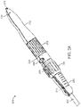
- FIG. 1 illustrates delivery system 100, according to an embodiment.
- Delivery system 100 can include handle 200 and catheter 300.
- Handle 200 can include front grip 210, rear grip 212, valve release knob 202, support arm knob 204, safety stop button 206, handle decoupling button 208, and decoupling portion 209.
- Catheter 300 can include outer shaft 302 and capsule 304.
- Capsule 304 can include proximal capsule portion 306, distal capsule portion 308, intermediate shaft 310, valve containment sleeve 312, and capsule tip 314.
- valve containment sleeve 312 can be a cylindrical polymer sleeve, configured to retain a heart valve prosthesis within capsule 304.
- capsule tip 314 can be an atraumatic tip to prevent damage to the body lumen as delivery system 100 is advanced through the body.
- capsule tip 314 can include an opening at its distal end to allow delivery system 100 to pass over a guide wire.
- capsule tip 314 can be radiopaque to facilitate locating delivery system 100 within the body using medical imaging.
- FIGS. 2A-2C illustrate close-up views of handle 200, according to an embodiment.
- Handle 200 can include front grip 210 and rear grip 212.
- Front grip 210 and rear grip 212 can be ergonomically designed to facilitate grasping of handle 200 by the user.
- Front grip 210 and rear grip 212 can be made of a moldable material, such as plastic or rubber, which can provide a smooth and frictional gripping surface.
- Front grip 210 and rear grip 212 can include grip flush ports 214, which can be used, for example, to remove air or add fluid to delivery system 100.
- Rear grip 212 can also include end flush port 216, which can also be used for these purposes, and additionally for inserting surgical tools through handle 200.
- front grip 210 (and/or rear grip 212) can include grooves 218 to further facilitate gripping handle 200.
- Handle 200 can also include support arm knob 204, valve release knob 202, safety stop button 206, and handle decoupling button 208. These features can be used to deploy the valve prosthesis and rejoin the capsule portions after deployment, and will be described in further detail below.
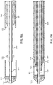
- FIGS. 3A-3D illustrate the deployment and retraction sequence for the valve prosthesis contained within capsule 304, according to an embodiment.
- FIG. 3A illustrates the initial retraction of outer shaft 302 and proximal capsule portion 306, as indicated by the arrow.
- Proximal capsule portion 306 can be retracted in the proximal direction, for example, by rotating support arm knob 204.
- support arm knob is exemplary.
- the disclosure includes knobs, slides, switches and other similar structures that can be activated to cause proximal capsule portion 306 to move axially.
- a safety stop feature can be located on handle 200, for example, within support arm knob 204, and can prevent proximal retraction of proximal capsule portion 306 beyond a predetermined distance.
- the safety stop feature can permit only partial deployment of the valve prosthesis support arms. Medical imaging can be used to determine the location of the support arms, and, if not in the proper location, the valve prosthesis can be repositioned or recaptured.
- the user can activate safety stop button 206 on support arm knob 204 to allow further proximal retraction of proximal capsule portion 306, as indicated by the arrow in FIG. 3B .
- the safety stop button can be a button, switch, knob, or other similar structures that can prevent proximal retraction of proximal capsule portion 306.
- FIG. 3B illustrates capsule 304 with proximal capsule portion 306 in a fully retracted position.
- proximal dome 316 which can be located at a proximal end of intermediate shaft 310, can be exposed.
- Proximal dome 316 can facilitate mating of proximal capsule portion 306 and distal capsule portion 308.
- Proximal dome 316 can include flushing slots 318, which can deliver a flushing fluid to the distal end of catheter 300.
- intermediate shaft 310 shown in FIG. 3B can be stationary relative to outer shaft 302 and inner shaft 320.
- valve containment sleeve 312 can still contain the inflow section of the valve prosthesis.
- FIG. 3C illustrates advancement of distal capsule portion 308 in the distal direction, as indicated by the arrow.
- Distal capsule portion 308 can be advanced distally, such as by rotating valve release knob 202.
- valve release knob is exemplary.
- valve release knob the disclosure includes knobs, slides, switches and other similar structures that can be activated to cause distal capsule portion 308 to move axially.
- Valve release knob 202 can control inner shaft 320, which, in certain embodiments, can move within an interior lumen of intermediate shaft 310, and can be connected to distal capsule portion 308.
- valve retainer 322 By advancing distal capsule portion 308, and thus valve containment sleeve 312, in the distal direction, valve retainer 322 can be exposed, thus releasing the valve prosthesis.
- Valve containment sleeve 312 can form a frictional interference fit with valve retainer 322, which can prevent distal capsule portion 308 from advancing too far in the distal direction.
- FIG. 3D illustrates proximal retraction of distal capsule portion 308.
- Manual retraction of distal capsule portion 308 can be performed, for example, by rotating valve release knob 202 in a direction opposite to the direction that advances distal capsule portion 308.
- Manual retraction of distal capsule portion 308 can also be performed by pressing handle decoupling button 208, which can decouple decoupling portion 209 of handle 200. The user can then pull decoupling portion 209 of handle 200 proximally. This movement can pull inner shaft 320, which can be connected to distal capsule portion 308, in the proximal direction, thus retracting distal capsule portion 308 proximally to mate with proximal capsule portion 306.
- Once capsule 304 is closed, delivery system 100 can be safely retracted through the deployed valve prosthesis and removed from the body.
- FIGS. 4A and 4B illustrate an interior view of support arm knob 204 and the safety stop mechanism, according to an embodiment.
- screw engager 302A of outer shaft 302 can engage support arm deployment screw 220.
- safety stop button 206 can be in a spring-loaded safety position, as shown in FIG. 4A . Once screw engager 302A reaches stopper 206A of safety stop button 206, outer shaft 302 is prevented from being retracted further in the proximal direction. At this point, the support arms of the valve prosthesis are partially deployed, and can be repositioned or recaptured, if necessary.
- valve prosthesis Once the valve prosthesis is in the proper location, the user can slide safety stop button 206 in the proximal direction, which can move stopper 206A proximally within slot 222. Outer shaft 302 can then be further retracted within handle lumen 224 in the proximal direction to fully deploy the support arms of the valve prosthesis.
- FIGS. 5A and 5B illustrate the decoupling mechanism, according to an embodiment.
- FIG. 5A shows a partial interior view of handle decoupling portion 209.
- the handle decoupling mechanism can include one or more handle decoupling buttons 208, which can include coupling elements 211.
- handle decoupling buttons is exemplary.
- handle decoupling buttons the disclosure includes knobs, slides, switches and other similar structures that can be activated to allow decoupling of a proximal portion of handle 200.
- coupling elements 211 can engage a counterpart of support arm knob 204 to keep support arm knob 204 and handle decoupling portion 209 together during deployment of the valve prosthesis.
- handle decoupling buttons 208 which can decouple coupling elements 211, and allow handle decoupling portion 209 and the rest of the proximal portion of handle 200 to be retracted rapidly in the proximal direction. This movement occur manually, whereby the user pulls handle 200 in the proximal direction. This can retract inner shaft 320, and therefore distal capsule portion 308, in the proximal direction to mate with proximal capsule portion 306 and close capsule 304.
- FIGS. 6A and 6B illustrate a close-up view of valve retainer 322, according to an embodiment.
- Valve retainer 322 can include landing zone 324, retaining portion 326 and one or more valve notch 328.
- portions of valve retainer 322 can be radiopaque, which can facilitate locating the delivery system using medical imaging.
- valve retainer 322 can be connected to the distal end of intermediate shaft 310.
- Valve notch 328 can be either cut into the surface of retaining portion 326 or raised on the surface of retaining portion 326.
- Valve notch 328 can correspond to a feature on the valve prosthesis to retain the valve prosthesis within capsule 304 until deployment.
- Landing zone 324 can be a smooth cylindrical surface located at the distal end of valve retainer 322. Landing zone 324 can prevent prosthesis flaring when engaged with the capsule, and can eliminate hang up points. As inner shaft 320 is advanced in the distal direction to deploy the inflow part of the valve prosthesis from within distal capsule portion 308, valve containment sleeve 312 can ride up on landing zone 324. An interference fit can be created between valve containment sleeve 312 and landing zone 324 of valve retainer 322. This can prevent distal capsule portion 308 from advancing too far in the distal direction during deployment of the valve prosthesis.
- landing zone 324 can be made of a low durometer polymer or rubber and retaining portion 326 can be made of metal, such as stainless steel.
- FIG. 6C illustrates a close-up view of valve retainer 322, according to another embodiment.
- Valve retainer 322 can be made from metal which has a notch, indentation and/or a mark on the side of landing zone 324, such as notch 332.
- Notch 332 can facilitate positioning of the delivery catheter under fluoroscopy by providing a differentiating appearance to aid with accurate deployment of the prosthesis.
- landing zone 324 can be configured to accommodate notch 332 and allow it to be covered by polymer sleeve 330 to cover the gap created by notch 332 to maintain proper fit between valve retainer 322 and capsule 304.
- Polymer sleeve 330 can be non-radiopaque, thus allowing valve retainer 322 to have features to facilitate accurate positioning while maintaining a round profile for a smooth fit with capsule 304 and for a smooth edge for retracting valve retainer 322 through the prosthesis after deployment.
- FIGS. 7A and 7B illustrate a capsule centering element, according to an embodiment.
- the capsule centering element can be centering frame 400.
- Centering frame 400 can be connected to intermediate shaft 310, such as by attachment ring 402, which can be located at either a proximal or distal end of centering frame 400.
- Attachment ring 402 can be crimped about intermediate shaft 310 to secure centering frame 400 to intermediate shaft 310.
- Centering frame 400 can be made of a self-expanding shape memory alloy, such as nitinol.
- centering frame 400 can be made from a laser-cut metal tube.
- centering frame 400 can be made of a plurality of wires 406, such as nitinol wires, welded to attachment ring 402.
- centering frame 400 can include radiopaque marker 404, which can facilitate positioning the valve prosthesis and aligning distal capsule portion 308 and proximal capsule portion 306 using medical imaging.
- centering frame 400 When the valve prosthesis is loaded in capsule 304, self-expanding centering frame 400 can be collapsed under the valve prosthesis. When the valve prosthesis is deployed, centering frame 400 can expand to provide a lead in for distal capsule portion 308 to mate with proximal capsule portion 306. The expansion of centering frame 400 can also facilitate disengaging the valve prosthesis from valve retainer 322.
- centering frame 400 can be coated with a biocompatible lubricant to facilitate guiding distal capsule portion 308 and proximal capsule portion 306 back together.
- centering frame 400 can at least partially recollapse as distal capsule portion 308 and proximal capsule portion 306 slide over centering frame 400 and back together.
- the capsule centering element can be centering funnel 500.
- Centering funnel 500 can be connected to intermediate shaft 310, such as by attachment ring 502, which can be located at either a proximal or distal end of centering funnel 500.
- Centering funnel 500 can be made of a self-expanding shape memory alloy, such as nitinol.
- centering funnel 500 can be a nitinol sheet rolled into a funnel or spring shape.
- centering funnel 500 can be constrained within an elastomeric sleeve, which can expand with centering funnel 500.
- centering funnel 500 coiled within proximal capsule portion 306 prior to delivery of the valve prosthesis.
- the expanded diameter of centering funnel 500 can be less than or equal to the diameter of distal capsule portion 308 and proximal capsule portion 306.
- proximal capsule portion 306 can be guided distally over centering funnel 500 to mate with distal capsule portion 308.
- distal capsule portion 308 can be pulled proximally over and around centering funnel 500 to mate with proximal capsule portion 306.
- centering funnel 500 can expand in diameter, thus creating a funnel shape to provide a guide for distal capsule portion 308 to mate with proximal capsule portion 306.
- centering funnel 500 can be manually expanded, such as by balloon inflation.
- centering funnel 500 can be coated with a biocompatible lubricant to facilitate guiding distal capsule portion 308 and proximal capsule portion 306 back together.
- centering funnel 500 can at least partially recollapse as distal capsule portion 308 and proximal capsule portion 306 slide over centering funnel 500 and back together.
- the capsule centering element can be structures such as, but not limited to, a cell-like stent structure or a braided cylinder, attached to intermediate shaft 310 by attachment ring 402 at one or more end.
- the capsule centering element can be centering shaft 600.
- Centering shaft 600 can be, for example, a polymer or composite shaft that can slide independently along intermediate shaft 310. Centering shaft 600 can be retracted proximately to allow the valve prosthesis to be loaded within capsule 304 prior to the valve replacement procedure.
- centering shaft 600 can have a continuous proximal profile and tapered tip 602, which can facilitate mating of distal capsule portion 308 with proximal capsule portion 306. After the valve prosthesis is deployed, centering shaft 600 can be advanced distally out of proximal capsule portion 306.
- Centering shaft 600 can be advanced to the proximal face of valve retainer 322 to facilitate disengaging the valve prosthesis from valve retainer 322.
- Distal capsule portion 308 can then be retracted proximally, such as by rotating valve release knob 202 to retract inner shaft 320 in the proximal direction.
- Distal capsule portion 308 can slide over tapered tip 602 of centering shaft 600.
- Proximal capsule portion 306 can also be advanced distally to concentrically mate proximal capsule portion 306 with distal capsule portion 308.
- centering shaft 600 can be coated with a biocompatible lubricant to facilitate guiding distal capsule portion 308 and proximal capsule portion 306 back together.
- proximal retraction of distal capsule portion 306 can be performed by activating handle decoupling button 208.
- centering shaft 600 can include centering dome 604.
- Centering dome 604 can include distal taper 606 and proximal taper 608.
- centering shaft 600 can operate in a mechanistically similar manner as in FIGS. 9A and 9B . After distal capsule portion 308 is advanced distally to deploy the valve prosthesis, centering shaft 600 can be advanced distally up to valve retainer 322 to facilitate disengaging the valve prosthesis from valve retainer 322.
- Distal capsule portion 308 can be retracted proximally such that distal capsule portion 308 and valve containment sleeve 312 slide over distal taper 606 of centering dome 604.
- Proximal capsule portion 306 can be advanced in the distal direction over proximal taper 608 of centering dome 604 to mate with distal capsule portion 308.
- proximal retraction of distal capsule portion 306 can be performed by activating handle decoupling button 208.
- the desired valve implantation location Prior to the procedure, the desired valve implantation location should be determined. This can be done with the assistance of medical imaging, such as a CT scan.
- the implantation location can generally be located within the aortic sinus such that the distal part of the heart valve prosthesis engages the leaflets of the native aortic valve, and the proximal part of the heart valve prosthesis engages the inner wall of the ascending aorta.
- Alternative implantation sites can be used, and the optimal implantation site can be determined for each individual patient.
- the chest can be prepared and the ascending aorta can be accessed, such as by a mini-sternotomy or a thoracotomy.
- the user can place delivery system 100 over a guide wire and advance delivery system 100 through the ascending aorta.
- medical imaging can be used to locate features of delivery system 100 to facilitate positioning of delivery system 100 at the desired deployment location.
- the user can, for example, rotate support arm knob 204 to retract outer shaft 302, and therefore proximal capsule portion 306, to partially release the valve support arms. If the support arms are not in the desired deployment location, the valve prosthesis can be repositioned or recaptured. Once the user verifies that the support arms are correctly positioned, proximal capsule portion 306 can be fully retracted. In certain examples this can be accomplished by pressing safety stop button 206 and further rotating support arm knob 204. The user can then advance distal capsule portion 308, for example, by rotating valve release knob 202. Once the valve prosthesis is fully deployed, the user can activate handle decoupling button 208 to initiate rapid closure of capsule 304. The user can then retract delivery system 100 through the deployed valve prosthesis and remove it from the body. The user can then close the incision by standard clinical techniques.
- distal capsule portion 308 can advance centering shaft 600 in the distal direction.
- Distal capsule portion 308 can then be retracted proximally over tapered tip 602 of centering shaft 600.
- Proximal capsule portion 306 can be advanced distally to mate proximal capsule portion 306 with distal capsule portion 308.
- a self-expanding capsule centering element can expand after deployment of the valve prosthesis. The capsule centering element can help guide distal capsule portion 308 and proximal capsule portion 306 back together.
Landscapes
- Health & Medical Sciences (AREA)
- Cardiology (AREA)
- Engineering & Computer Science (AREA)
- Biomedical Technology (AREA)
- Heart & Thoracic Surgery (AREA)
- Transplantation (AREA)
- Oral & Maxillofacial Surgery (AREA)
- Vascular Medicine (AREA)
- Life Sciences & Earth Sciences (AREA)
- Animal Behavior & Ethology (AREA)
- General Health & Medical Sciences (AREA)
- Public Health (AREA)
- Veterinary Medicine (AREA)
- Prostheses (AREA)
Description
- The present disclosure relates to systems for delivering a prosthesis to a desired location in the body of a patient and methods for delivering and implanting a prosthesis. More particularly, the present disclosure relates to prosthetic valve delivery systems for deploying a heart valve prosthesis within a body lumen and to methods of delivering such a prosthesis to a desired location in the body.
- Currently, replacement of a deficient cardiac valve is often performed by placing the patient under extracorporeal circulation, temporarily stopping the heart, opening the thorax (e.g., by a sternotomy), surgically opening the heart, excising the deficient valve, and then implanting a prosthetic valve in its place. This procedure generally requires prolonged patient hospitalization, as well as extensive and often painful recovery.
- Recently, minimally invasive approaches have been developed to facilitate catheter-based implantation of valve prostheses in the beating heart, intending to obviate the need for the classic sternotomy and cardiopulmonary bypass. For example,
U.S. Patent No. 8,016,877 to Seguin et al. illustrates a technique and a device for replacing a deficient heart valve by percutaneous route. An expandable prosthetic valve can be compressed about a catheter, inserted inside a body lumen, such as the femoral artery, and delivered to a desired location in the heart. Additionally,U.S. Patent No. 7,914,569 to Nguyen et al. discloses advancing a catheter containing a prosthesis in a retrograde manner through the femoral artery and into the descending aorta, over the aortic arch, through the ascending aorta and inside the defective aortic valve. This procedure can be assisted by fluoroscopic guidance. Once the position of the catheter containing the prosthesis is confirmed, a sheath containing the prosthesis can be moved proximally, allowing the valve prosthesis to self-expand. - Other techniques for delivering prosthetic heart valves via a catheter include transapical and trans-aortic approaches for aortic valve replacement, typically involving the use of an introducer port, i.e., a large-bore overtube, of a trocar. A crimped, framed valve prosthesis reversibly coupled to a delivery catheter can be transcatheterally advanced toward the native valve, where it can either be deployed using a balloon catheter, or, alternatively, using a self-expandable system.
- With regard to the structure of the heart valve prosthesis itself,
U.S. Patent No. 7,914,569 to Nguyen et al. describes an example prosthesis for percutaneous transluminal delivery. The heart valve prosthesis can have a self-expanding multi-level frame that supports a valve body with a skirt and plurality of leaflets. The frame can be contracted during percutaneous transluminal delivery and expanded to an hourglass shape upon deployment within the native heart valve. -
WO 2012/038550 A1 describes a stent valve, delivery apparatus and method therefore.WO 2011/144351 A2 describes a catheter system for introducing an expandable heart valve stent into the body of a patient, insertion system with a catheter system and medical device for treatment of a heart valve defect. -
WO 23011/094527 A1 -
WO 2009/091509 A1 describes delivery and retrieval systems for collapsible/expandable prosthetic heart valves. -
WO 2010/045297 A2 describes a delivery system for deployment of medical devices. - The present disclosure describes delivery systems for implanting a heart valve prosthesis through a trans-aortic pathway. By directly accessing the aorta, it is possible to accurately implant a prosthetic valve without the need for cardiopulmonary bypass, although the disclosed delivery systems can also be used with cardiopulmonary bypass. Furthermore, the delivery systems disclosed herein can allow for quick and accurate retraction of a distal portion of the capsule member used to contain the valve prosthesis. It is understood that while the disclosure refers specifically to a trans-aortic procedure, the delivery systems and methods disclosed herein can also be used for any access route, vessel or location within the heart and vasculature.
- In certain embodiments, the delivery systems can include a handle assembly which can include a first control mechanism, a second control mechanism, and a decoupling mechanism. The delivery systems can also include a delivery catheter extending from the handle assembly. The delivery catheter can include an outer shaft, which can be controlled by the first control mechanism, and a prosthesis containing capsule comprising a proximal capsule portion connected to the outer shaft and a distal capsule portion releasably coupled to the proximal capsule portion. The capsule can also include a distal tip and a prosthesis containment sleeve. The delivery catheter can also include an intermediate shaft having a prosthesis retainer located at its distal end, and an inner shaft which can be controlled by the second control mechanism and can be connected to the distal capsule portion. In certain embodiments, the delivery system can also include a safety mechanism, which can be connected to the first control mechanism, and configured to prevent proximal retraction of the outer shaft beyond a predetermined distance. In certain embodiments, the delivery system can also include a capsule centering element such as, but not limited to, a self-expanding frame, a self-expanding funnel, or a centering shaft.
- Also disclosed herein are catheter tips, which can include a proximal capsule portion and a distal capsule portion releasably coupled to the proximal capsule portion. The distal capsule portion can include a distal tip, connected to an inner shaft of the catheter, and a prosthesis containment sleeve. The catheter tip can also include an intermediate shaft having a prosthesis retainer located at a distal end. In certain embodiments, the catheter tip can include a centering shaft having a tapered distal nose and configured to move axially along the intermediate shaft. In certain embodiments the catheter tip can include a capsule centering element attached to the intermediate shaft, located proximally from the prosthesis retainer and configured to guide the distal capsule portion and the proximal capsule portion back together after separating to deploy the valve prosthesis.
- In order to deliver the prosthesis, the delivery system can be introduced into a patient's aorta and the delivery catheter can be advanced within the aorta to a deployment location. The first control mechanism can be activated to proximally retract the outer shaft and proximal capsule portion, and the second control mechanism can be activated to distally advance the distal capsule portion to release the valve prosthesis. The capsule can be closed by activating a decoupling mechanism to close the distal capsule portion and proximal capsule portion together. The delivery system can then be retracted proximally through the deployed valve prosthesis and removed from the body.
- The accompanying figures, which are incorporated herein, form part of the specification and illustrate embodiments of prosthetic valve delivery systems and methods (the methods not falling within the scope of the claims) of delivering a valve prosthesis to a desired location in a body of a patient. Together with the description, the figures further serve to explain the principles of and allow for the making and using of the prosthetic valve delivery systems and methods described herein. These figures are intended to be illustrative, not limiting. Although the disclosure is generally described in the context of these embodiments, it should be understood that it is not intended to limit the scope of the disclosure to these particular embodiments. In the drawings, like reference numbers indicate identical or functionally similar elements.
-
FIG. 1 illustrates a delivery system, according to an embodiment. -
FIG. 2A shows a close-up view of the handle, according to an embodiment. -
FIG. 2B shows a close-up view of the front grip, according to an embodiment. -
FIG. 2C shows a close-up view of the rear grip, according to an embodiment. -
FIGS. 3A-3D illustrate the valve deployment sequence, according to an embodiment. -
FIGS. 4A-4B illustrate an interior view of the handle, according to an embodiment. -
FIG. 5A illustrates a partial interior view of the housing for the decoupling mechanism, according to an embodiment. -
FIG. 5B illustrates the handle after being decoupled, according to an embodiment. -
FIGS. 6A-6C illustrate close-up views of the valve retainer, according to certain embodiments. -
FIGS. 7A-7B illustrate the centering frame attached to the delivery system and separately, according to an embodiment. -
FIGS. 8A-8B illustrate the centering funnel attached to the delivery system and separately, according to an embodiment. -
FIGS. 9A-9B illustrate the centering shaft, according to an embodiment. -
FIGS. 10A-10B illustrate the centering shaft including a centering dome, according to an embodiment. - While the disclosure refers to illustrative embodiments for particular applications, it should be understood that the disclosure is not limited thereto. Modifications can be made to the embodiments described herein without departing from the spirit and scope of the present disclosure. Those skilled in the art with access to this disclosure will recognize additional modifications, applications, and embodiments within the scope of this disclosure and additional fields in which the disclosed examples could be applied. Therefore, the following detailed description is not meant to be limiting. Further, it is understood that the systems and methods described below can be implemented in many different embodiments of hardware. Any actual hardware described is not meant to be limiting. The operation and behavior of the systems and methods presented are described with the understanding that modifications and variations of the embodiments are possible given the level of detail presented.
- References to "one embodiment," "an embodiment," "in certain embodiments," etc., indicate that the embodiment described may include a particular feature, structure, or characteristic, but every embodiment may not necessarily include the particular feature, structure, or characteristic. Moreover, such phrases are not necessarily referring to the same embodiment. Further, when a particular feature, structure, or characteristic is described in connection with an embodiment, it is submitted that it is within the knowledge of one skilled in the art to affect such feature, structure, or characteristic in connection with other embodiments whether or not explicitly described.
- The delivery systems disclosed herein can include a moldable handle capable of translating linear relative movement between multiple shafts simultaneously to deliver a valve prosthesis. The delivery systems can include a two-part prosthesis containment capsule which can maintain a compressible interference fit, mitigating risks associated with snagging during retraction of the delivery system. The delivery system handle can be reversibly decoupled, allowing for rapid closure of the prosthesis containment capsule after delivery of the prosthesis. The decoupling mechanism can be user operated and can include a safety feature to prevent premature actuation.
- The delivery system can also include a safety stop feature, which can permit only partial deployment of the valve prosthesis support arms, such as by impeding the pathway of the support arm screw, to allow repositioning or recapturing of the prosthesis. The user can then choose to release the safety stop button to allow completion of the support arm deployment.
- The delivery system can also include a delivery catheter, which can have a two-part prosthesis containment capsule divided into distal and proximal portions. To deploy the prosthesis, the proximal capsule portion can be retracted proximally to release the prosthesis arms, which can engage with the ascending aorta. The distal capsule portion can be advanced distally to release the prosthesis inflow section, which can engage the native leaflets of the heart valve. After deployment, the distal and proximal capsule portions can be returned to their closed, pre-deployment configuration to allow safe removal of the delivery system through the deployed prosthesis.
- Without the prosthesis loaded within the capsule, the open capsule sections may not align concentrically after deployment, and can create "open mouth" sections which can damage or snag on the deployed prosthesis. In the embodiments of the invention the delivery system can include a centering element, which can facilitate guiding the two capsule sections back together and align them concentrically. In certain embodiments, the centering element can be a self-expanding centering frame. During loading and deployment, the center frame can be collapsed under the valve prosthesis. Upon deployment, the centering frame can expand, which can also help disengage the valve prosthesis from the valve retainer. Once the valve prosthesis is deployed, the distal capsule portion can be retracted over the centering frame's tapered distal profile to align it concentrically with the proximal capsule portion. The proximal capsule portion can then be advanced over the centering frame's tapered proximal profile to concentrically align it with the distal capsule portion.
- In certain examples not falling within the scope of the claims the centering element can be a centering shaft with a tapered distal profile, which can facilitate guiding the two capsule portions together and align them concentrically. During loading and deployment, the centering shaft can be retracted proximally from the valve prosthesis. Once the valve prosthesis is deployed, the centering shaft can be advanced to the proximal face of the valve retainer, which can help disengage the valve prosthesis from the valve retainer. At this point, the distal capsule portion can be retracted over the centering shaft's tapered distal profile to align it concentrically with the proximal capsule portion. The proximal capsule portion can then be advanced over the centering shaft to concentrically align it with the distal capsule portion. The delivery system can then be safely retracted through the deployed valve prosthesis.
-
FIG. 1 illustratesdelivery system 100, according to an embodiment.Delivery system 100 can include handle 200 andcatheter 300. Handle 200 can includefront grip 210,rear grip 212,valve release knob 202,support arm knob 204,safety stop button 206, handledecoupling button 208, anddecoupling portion 209.Catheter 300 can includeouter shaft 302 andcapsule 304.Capsule 304 can includeproximal capsule portion 306,distal capsule portion 308,intermediate shaft 310,valve containment sleeve 312, andcapsule tip 314. - In certain embodiments,
valve containment sleeve 312 can be a cylindrical polymer sleeve, configured to retain a heart valve prosthesis withincapsule 304. In certain embodiments,capsule tip 314 can be an atraumatic tip to prevent damage to the body lumen asdelivery system 100 is advanced through the body. In certain embodiments,capsule tip 314 can include an opening at its distal end to allowdelivery system 100 to pass over a guide wire. In certain embodiments,capsule tip 314 can be radiopaque to facilitate locatingdelivery system 100 within the body using medical imaging. -
FIGS. 2A-2C illustrate close-up views ofhandle 200, according to an embodiment. Handle 200 can includefront grip 210 andrear grip 212.Front grip 210 andrear grip 212 can be ergonomically designed to facilitate grasping ofhandle 200 by the user.Front grip 210 andrear grip 212 can be made of a moldable material, such as plastic or rubber, which can provide a smooth and frictional gripping surface.Front grip 210 andrear grip 212 can include gripflush ports 214, which can be used, for example, to remove air or add fluid todelivery system 100.Rear grip 212 can also include endflush port 216, which can also be used for these purposes, and additionally for inserting surgical tools throughhandle 200. As shown inFIG. 2B , front grip 210 (and/or rear grip 212) can includegrooves 218 to further facilitategripping handle 200. - Handle 200 can also include
support arm knob 204,valve release knob 202,safety stop button 206, and handledecoupling button 208. These features can be used to deploy the valve prosthesis and rejoin the capsule portions after deployment, and will be described in further detail below. -
FIGS. 3A-3D illustrate the deployment and retraction sequence for the valve prosthesis contained withincapsule 304, according to an embodiment.FIG. 3A illustrates the initial retraction ofouter shaft 302 andproximal capsule portion 306, as indicated by the arrow.Proximal capsule portion 306 can be retracted in the proximal direction, for example, by rotatingsupport arm knob 204. It is understood that the term support arm knob is exemplary. By support arm knob, the disclosure includes knobs, slides, switches and other similar structures that can be activated to causeproximal capsule portion 306 to move axially. - A safety stop feature can be located on
handle 200, for example, withinsupport arm knob 204, and can prevent proximal retraction ofproximal capsule portion 306 beyond a predetermined distance. The safety stop feature can permit only partial deployment of the valve prosthesis support arms. Medical imaging can be used to determine the location of the support arms, and, if not in the proper location, the valve prosthesis can be repositioned or recaptured. Once in the proper deployment location, the user can activatesafety stop button 206 onsupport arm knob 204 to allow further proximal retraction ofproximal capsule portion 306, as indicated by the arrow inFIG. 3B . It is understood that reference to the safety stop button is exemplary, and not meant to be limiting. The safety stop button can be a button, switch, knob, or other similar structures that can prevent proximal retraction ofproximal capsule portion 306. -
FIG. 3B illustratescapsule 304 withproximal capsule portion 306 in a fully retracted position. In this fully retracted position,proximal dome 316, which can be located at a proximal end ofintermediate shaft 310, can be exposed.Proximal dome 316 can facilitate mating ofproximal capsule portion 306 anddistal capsule portion 308.Proximal dome 316 can include flushingslots 318, which can deliver a flushing fluid to the distal end ofcatheter 300. In certain embodiments,intermediate shaft 310 shown inFIG. 3B can be stationary relative toouter shaft 302 andinner shaft 320. - At the stage of deployment illustrated in
FIG. 3B ,valve containment sleeve 312 can still contain the inflow section of the valve prosthesis.FIG. 3C illustrates advancement ofdistal capsule portion 308 in the distal direction, as indicated by the arrow.Distal capsule portion 308 can be advanced distally, such as by rotatingvalve release knob 202. It is understood that the term valve release knob is exemplary. By valve release knob, the disclosure includes knobs, slides, switches and other similar structures that can be activated to causedistal capsule portion 308 to move axially. -
Valve release knob 202 can controlinner shaft 320, which, in certain embodiments, can move within an interior lumen ofintermediate shaft 310, and can be connected todistal capsule portion 308. By advancingdistal capsule portion 308, and thusvalve containment sleeve 312, in the distal direction,valve retainer 322 can be exposed, thus releasing the valve prosthesis.Valve containment sleeve 312 can form a frictional interference fit withvalve retainer 322, which can preventdistal capsule portion 308 from advancing too far in the distal direction. -
FIG. 3D illustrates proximal retraction ofdistal capsule portion 308. Manual retraction ofdistal capsule portion 308 can be performed, for example, by rotatingvalve release knob 202 in a direction opposite to the direction that advancesdistal capsule portion 308. Manual retraction ofdistal capsule portion 308 can also be performed by pressinghandle decoupling button 208, which can decoupledecoupling portion 209 ofhandle 200. The user can then pulldecoupling portion 209 ofhandle 200 proximally. This movement can pullinner shaft 320, which can be connected todistal capsule portion 308, in the proximal direction, thus retractingdistal capsule portion 308 proximally to mate withproximal capsule portion 306. Oncecapsule 304 is closed,delivery system 100 can be safely retracted through the deployed valve prosthesis and removed from the body. -
FIGS. 4A and 4B illustrate an interior view ofsupport arm knob 204 and the safety stop mechanism, according to an embodiment. By way of example, as the user rotatessupport arm knob 204, screwengager 302A ofouter shaft 302 can engage supportarm deployment screw 220. Generally,safety stop button 206 can be in a spring-loaded safety position, as shown inFIG. 4A . Oncescrew engager 302A reachesstopper 206A ofsafety stop button 206,outer shaft 302 is prevented from being retracted further in the proximal direction. At this point, the support arms of the valve prosthesis are partially deployed, and can be repositioned or recaptured, if necessary. Once the valve prosthesis is in the proper location, the user can slidesafety stop button 206 in the proximal direction, which can movestopper 206A proximally withinslot 222.Outer shaft 302 can then be further retracted withinhandle lumen 224 in the proximal direction to fully deploy the support arms of the valve prosthesis. -
FIGS. 5A and 5B illustrate the decoupling mechanism, according to an embodiment.FIG. 5A shows a partial interior view ofhandle decoupling portion 209. The handle decoupling mechanism can include one or morehandle decoupling buttons 208, which can includecoupling elements 211. It is understood that the term handle decoupling buttons is exemplary. By handle decoupling buttons, the disclosure includes knobs, slides, switches and other similar structures that can be activated to allow decoupling of a proximal portion ofhandle 200. In certain embodiments,coupling elements 211 can engage a counterpart ofsupport arm knob 204 to keepsupport arm knob 204 and handledecoupling portion 209 together during deployment of the valve prosthesis. Once the valve prosthesis is deployed, the user can press handledecoupling buttons 208, which can decouplecoupling elements 211, and allowhandle decoupling portion 209 and the rest of the proximal portion ofhandle 200 to be retracted rapidly in the proximal direction. This movement occur manually, whereby the user pulls handle 200 in the proximal direction. This can retractinner shaft 320, and thereforedistal capsule portion 308, in the proximal direction to mate withproximal capsule portion 306 andclose capsule 304. -
FIGS. 6A and 6B illustrate a close-up view ofvalve retainer 322, according to an embodiment.Valve retainer 322 can includelanding zone 324, retainingportion 326 and one ormore valve notch 328. In certain embodiments, portions ofvalve retainer 322 can be radiopaque, which can facilitate locating the delivery system using medical imaging. As illustrated inFIG. 6B ,valve retainer 322 can be connected to the distal end ofintermediate shaft 310.Valve notch 328 can be either cut into the surface of retainingportion 326 or raised on the surface of retainingportion 326.Valve notch 328 can correspond to a feature on the valve prosthesis to retain the valve prosthesis withincapsule 304 until deployment.Landing zone 324 can be a smooth cylindrical surface located at the distal end ofvalve retainer 322.Landing zone 324 can prevent prosthesis flaring when engaged with the capsule, and can eliminate hang up points. Asinner shaft 320 is advanced in the distal direction to deploy the inflow part of the valve prosthesis from withindistal capsule portion 308,valve containment sleeve 312 can ride up onlanding zone 324. An interference fit can be created betweenvalve containment sleeve 312 andlanding zone 324 ofvalve retainer 322. This can preventdistal capsule portion 308 from advancing too far in the distal direction during deployment of the valve prosthesis. In certain embodiments, landingzone 324 can be made of a low durometer polymer or rubber and retainingportion 326 can be made of metal, such as stainless steel. -
FIG. 6C illustrates a close-up view ofvalve retainer 322, according to another embodiment.Valve retainer 322 can be made from metal which has a notch, indentation and/or a mark on the side oflanding zone 324, such asnotch 332.Notch 332 can facilitate positioning of the delivery catheter under fluoroscopy by providing a differentiating appearance to aid with accurate deployment of the prosthesis. In certain embodiments, landingzone 324 can be configured to accommodatenotch 332 and allow it to be covered bypolymer sleeve 330 to cover the gap created bynotch 332 to maintain proper fit betweenvalve retainer 322 andcapsule 304.Polymer sleeve 330 can be non-radiopaque, thus allowingvalve retainer 322 to have features to facilitate accurate positioning while maintaining a round profile for a smooth fit withcapsule 304 and for a smooth edge for retractingvalve retainer 322 through the prosthesis after deployment. -
FIGS. 7A and 7B illustrate a capsule centering element, according to an embodiment. In certain embodiments, the capsule centering element can be centeringframe 400. Centeringframe 400 can be connected tointermediate shaft 310, such as byattachment ring 402, which can be located at either a proximal or distal end of centeringframe 400.Attachment ring 402 can be crimped aboutintermediate shaft 310 to secure centeringframe 400 tointermediate shaft 310. Centeringframe 400 can be made of a self-expanding shape memory alloy, such as nitinol. In certain embodiments, centeringframe 400 can be made from a laser-cut metal tube. In certain embodiments, centeringframe 400 can be made of a plurality ofwires 406, such as nitinol wires, welded toattachment ring 402. In certain embodiments, centeringframe 400 can includeradiopaque marker 404, which can facilitate positioning the valve prosthesis and aligningdistal capsule portion 308 andproximal capsule portion 306 using medical imaging. - When the valve prosthesis is loaded in
capsule 304, self-expanding centeringframe 400 can be collapsed under the valve prosthesis. When the valve prosthesis is deployed, centeringframe 400 can expand to provide a lead in fordistal capsule portion 308 to mate withproximal capsule portion 306. The expansion of centeringframe 400 can also facilitate disengaging the valve prosthesis fromvalve retainer 322. In certain embodiments, centeringframe 400 can be coated with a biocompatible lubricant to facilitate guidingdistal capsule portion 308 andproximal capsule portion 306 back together. In certain embodiments, centeringframe 400 can at least partially recollapse asdistal capsule portion 308 andproximal capsule portion 306 slide over centeringframe 400 and back together. - As illustrated in
FIGS. 8A and 8B , in certain embodiments, the capsule centering element can be centeringfunnel 500. Centeringfunnel 500 can be connected tointermediate shaft 310, such as byattachment ring 502, which can be located at either a proximal or distal end of centeringfunnel 500. Centeringfunnel 500 can be made of a self-expanding shape memory alloy, such as nitinol. In certain embodiments, as illustrated, for example, inFIG. 8B , centeringfunnel 500 can be a nitinol sheet rolled into a funnel or spring shape. In certain embodiments, centeringfunnel 500 can be constrained within an elastomeric sleeve, which can expand with centeringfunnel 500.FIG. 8B provides a view along a longitudinal axis ofdelivery system 100, showing centeringfunnel 500 coiled withinproximal capsule portion 306 prior to delivery of the valve prosthesis. Generally, the expanded diameter of centeringfunnel 500 can be less than or equal to the diameter ofdistal capsule portion 308 andproximal capsule portion 306. In certain embodiments,proximal capsule portion 306 can be guided distally over centeringfunnel 500 to mate withdistal capsule portion 308. In certain embodiments,distal capsule portion 308 can be pulled proximally over and around centeringfunnel 500 to mate withproximal capsule portion 306. - Once the valve prosthesis is deployed, centering
funnel 500 can expand in diameter, thus creating a funnel shape to provide a guide fordistal capsule portion 308 to mate withproximal capsule portion 306. In certain embodiments, centeringfunnel 500 can be manually expanded, such as by balloon inflation. In certain embodiments, centeringfunnel 500 can be coated with a biocompatible lubricant to facilitate guidingdistal capsule portion 308 andproximal capsule portion 306 back together. In certain embodiments, centeringfunnel 500 can at least partially recollapse asdistal capsule portion 308 andproximal capsule portion 306 slide over centeringfunnel 500 and back together. - In certain embodiments, the capsule centering element can be structures such as, but not limited to, a cell-like stent structure or a braided cylinder, attached to
intermediate shaft 310 byattachment ring 402 at one or more end. - As illustrated in
FIGS. 9A and 9B , as well asFIGS. 10A and 10B , in certain examples not falling within the scope of the claims the capsule centering element can be centeringshaft 600. Centeringshaft 600 can be, for example, a polymer or composite shaft that can slide independently alongintermediate shaft 310. Centeringshaft 600 can be retracted proximately to allow the valve prosthesis to be loaded withincapsule 304 prior to the valve replacement procedure. In certainexamples centering shaft 600 can have a continuous proximal profile and taperedtip 602, which can facilitate mating ofdistal capsule portion 308 withproximal capsule portion 306. After the valve prosthesis is deployed, centeringshaft 600 can be advanced distally out ofproximal capsule portion 306. Centeringshaft 600 can be advanced to the proximal face ofvalve retainer 322 to facilitate disengaging the valve prosthesis fromvalve retainer 322.Distal capsule portion 308 can then be retracted proximally, such as by rotatingvalve release knob 202 to retractinner shaft 320 in the proximal direction.Distal capsule portion 308 can slide over taperedtip 602 of centeringshaft 600.Proximal capsule portion 306 can also be advanced distally to concentrically mateproximal capsule portion 306 withdistal capsule portion 308. In certain embodiments, centeringshaft 600 can be coated with a biocompatible lubricant to facilitate guidingdistal capsule portion 308 andproximal capsule portion 306 back together. In certain embodiments, proximal retraction ofdistal capsule portion 306 can be performed by activatinghandle decoupling button 208. - As illustrated in
FIGS. 10A and 10B , in certain examples not falling within the scope of theclaims centering shaft 600 can include centeringdome 604. Centeringdome 604 can includedistal taper 606 andproximal taper 608. In the examples shown inFIGS. 10A and 10B , centeringshaft 600 can operate in a mechanistically similar manner as inFIGS. 9A and 9B . Afterdistal capsule portion 308 is advanced distally to deploy the valve prosthesis, centeringshaft 600 can be advanced distally up tovalve retainer 322 to facilitate disengaging the valve prosthesis fromvalve retainer 322.Distal capsule portion 308 can be retracted proximally such thatdistal capsule portion 308 andvalve containment sleeve 312 slide overdistal taper 606 of centeringdome 604.Proximal capsule portion 306 can be advanced in the distal direction overproximal taper 608 of centeringdome 604 to mate withdistal capsule portion 308. In certain embodiments, proximal retraction ofdistal capsule portion 306 can be performed by activatinghandle decoupling button 208. - Methods of delivering a heart valve prosthesis are also disclosed. References to the figures are made by way of example, and are not meant to be limiting. Prior to the procedure, the desired valve implantation location should be determined. This can be done with the assistance of medical imaging, such as a CT scan. For trans-aortic prosthetic aortic valve implantation, the implantation location can generally be located within the aortic sinus such that the distal part of the heart valve prosthesis engages the leaflets of the native aortic valve, and the proximal part of the heart valve prosthesis engages the inner wall of the ascending aorta. Alternative implantation sites can be used, and the optimal implantation site can be determined for each individual patient.
- Generally, for a trans-aortic procedure, the chest can be prepared and the ascending aorta can be accessed, such as by a mini-sternotomy or a thoracotomy. In certain embodiments, the user can place
delivery system 100 over a guide wire and advancedelivery system 100 through the ascending aorta. In certain examples medical imaging can be used to locate features ofdelivery system 100 to facilitate positioning ofdelivery system 100 at the desired deployment location. - Once in the desired anatomical position, the user can, for example, rotate
support arm knob 204 to retractouter shaft 302, and thereforeproximal capsule portion 306, to partially release the valve support arms. If the support arms are not in the desired deployment location, the valve prosthesis can be repositioned or recaptured. Once the user verifies that the support arms are correctly positioned,proximal capsule portion 306 can be fully retracted. In certain examples this can be accomplished by pressingsafety stop button 206 and further rotatingsupport arm knob 204. The user can then advancedistal capsule portion 308, for example, by rotatingvalve release knob 202. Once the valve prosthesis is fully deployed, the user can activate handledecoupling button 208 to initiate rapid closure ofcapsule 304. The user can then retractdelivery system 100 through the deployed valve prosthesis and remove it from the body. The user can then close the incision by standard clinical techniques. - In certain examples after distally advancing
distal capsule portion 308 to deploy the valve prosthesis, the user can advance centeringshaft 600 in the distal direction.Distal capsule portion 308 can then be retracted proximally over taperedtip 602 of centeringshaft 600.Proximal capsule portion 306 can be advanced distally to mateproximal capsule portion 306 withdistal capsule portion 308. In certain examples a self-expanding capsule centering element can expand after deployment of the valve prosthesis. The capsule centering element can help guidedistal capsule portion 308 andproximal capsule portion 306 back together.
Claims (14)
- A catheter tip (304) comprising:a proximal capsule portion (306);a distal capsule portion (308), releasably coupled to the proximal capsule portion (306), comprising:a distal tip (314) for connecting to an inner shaft (320) of a delivery catheter (300); anda prosthesis containment sleeve (312);an intermediate shaft (310), having a prosthesis retainer (322) located at a distal end; anda self-expanding centering element (400) attached to the intermediate shaft (310), located proximally from the prosthesis retainer (322), and configured to guide the distal capsule portion (308) and the proximal capsule portion (306) together when closing distal and proximal capsule portions;characterised in that the self-expanding centering element (400) is configured such that, during loading and deployment, the self-expanding centering element (400) is collapsed under a valve prosthesis.
- The catheter tip (304) of claim 1, wherein the centering element (400) comprises a self-expanding frame (400) attached to the intermediate shaft (310) at either a proximal end or a distal end of the frame (400).
- The catheter tip (304) of claim 2, wherein the self-expanding frame (400) comprises a shape memory alloy.
- The catheter tip (304) of claim 1, wherein the centering element (400) comprises a plurality of nitinol wires.
- The catheter tip (304) of claim 1, wherein the centering element (400) comprises a self-expanding funnel (500) attached to the intermediate shaft (310) at a proximal end of the funnel (500).
- The catheter tip (304) of claim 5, wherein the centering funnel (500) is constrained within an elastomeric sleeve capable of expanding with the funnel (500).
- The catheter tip (304) of claim 5 or 6, wherein the self-expanding funnel (500) comprises a rolled nitinol sheet.
- The catheter tip (304) of claim 1, further comprising a self-expanding heart valve prosthesis located within the prosthesis containing capsule (304).
- A prosthesis delivery system (100) comprising:a handle assembly (200) comprising:a first control mechanism (204);a second control mechanism (202); anda decoupling mechanism (208, 209); anda delivery catheter (300) extending from the handle assembly (200) comprising:the catheter tip (304) according to any of claim 1 through 8;an outer shaft (302) controlled by the first control mechanism (204); andan inner shaft (320) controlled by the second control mechanism and connected to the distal capsule portion; wherein the proximal capsule portion is connected to the outer shaft.
- The prosthesis delivery system (100) of claim 9, further comprising a safety mechanism connected to the first control mechanism (204), and configured to prevent proximal retraction of the outer shaft (302) beyond a predetermined distance.
- The prosthesis delivery system (100) of claim 1, wherein the prosthesis retainer (322) comprises a proximal portion connected to the intermediate shaft (310), and a distal portion configured to create a compressible interference fit with the prosthesis containment sleeve (312).
- The prosthesis delivery system (100) of claim 1, wherein the intermediate shaft (310) is stationary relative to the outer shaft (302) and the inner shaft (320).
- The prosthesis delivery system (100) of claim 1, wherein the first and second control mechanisms (204, 202) are rotatable control knobs.
- The prosthesis delivery system (100) of any of claims 9 through 13, wherein the catheter tip (304) is a prosthesis containing capsule.
Applications Claiming Priority (2)
| Application Number | Priority Date | Filing Date | Title |
|---|---|---|---|
| US13/604,150 US9717595B2 (en) | 2012-09-05 | 2012-09-05 | Trans-aortic delivery system with containment capsule centering device |
| PCT/US2013/056890 WO2014039333A1 (en) | 2012-09-05 | 2013-08-27 | Trans-aortic delivery system with containment capsule centering device |
Publications (2)
| Publication Number | Publication Date |
|---|---|
| EP2892467A1 EP2892467A1 (en) | 2015-07-15 |
| EP2892467B1 true EP2892467B1 (en) | 2021-11-17 |
Family
ID=49151338
Family Applications (1)
| Application Number | Title | Priority Date | Filing Date |
|---|---|---|---|
| EP13759940.3A Active EP2892467B1 (en) | 2012-09-05 | 2013-08-27 | Trans-aortic delivery system with containment capsule centering device |
Country Status (3)
| Country | Link |
|---|---|
| US (2) | US9717595B2 (en) |
| EP (1) | EP2892467B1 (en) |
| WO (1) | WO2014039333A1 (en) |
Cited By (16)
| Publication number | Priority date | Publication date | Assignee | Title |
|---|---|---|---|---|
| US11311376B2 (en) | 2019-06-20 | 2022-04-26 | Neovase Tiara Inc. | Low profile prosthetic mitral valve |
| US11357622B2 (en) | 2016-01-29 | 2022-06-14 | Neovase Tiara Inc. | Prosthetic valve for avoiding obstruction of outflow |
| US11389294B2 (en) | 2012-05-30 | 2022-07-19 | Neovasc Tiara Inc. | Methods and apparatus for loading a prosthesis onto a delivery system |
| US11389291B2 (en) | 2013-04-04 | 2022-07-19 | Neovase Tiara Inc. | Methods and apparatus for delivering a prosthetic valve to a beating heart |
| US11413139B2 (en) | 2011-11-23 | 2022-08-16 | Neovasc Tiara Inc. | Sequentially deployed transcatheter mitral valve prosthesis |
| US11419720B2 (en) | 2010-05-05 | 2022-08-23 | Neovasc Tiara Inc. | Transcatheter mitral valve prosthesis |
| US11464631B2 (en) | 2016-11-21 | 2022-10-11 | Neovasc Tiara Inc. | Methods and systems for rapid retraction of a transcatheter heart valve delivery system |
| US11491006B2 (en) | 2019-04-10 | 2022-11-08 | Neovasc Tiara Inc. | Prosthetic valve with natural blood flow |
| US11497602B2 (en) | 2012-02-14 | 2022-11-15 | Neovasc Tiara Inc. | Methods and apparatus for engaging a valve prosthesis with tissue |
| US11602429B2 (en) | 2019-04-01 | 2023-03-14 | Neovasc Tiara Inc. | Controllably deployable prosthetic valve |
| US11737872B2 (en) | 2018-11-08 | 2023-08-29 | Neovasc Tiara Inc. | Ventricular deployment of a transcatheter mitral valve prosthesis |
| US11779742B2 (en) | 2019-05-20 | 2023-10-10 | Neovasc Tiara Inc. | Introducer with hemostasis mechanism |
| US11793640B2 (en) | 2017-08-25 | 2023-10-24 | Neovasc Tiara Inc. | Sequentially deployed transcatheter mitral valve prosthesis |
| US11998447B2 (en) | 2019-03-08 | 2024-06-04 | Neovasc Tiara Inc. | Retrievable prosthesis delivery system |
| US12109111B2 (en) | 2015-12-15 | 2024-10-08 | Neovasc Tiara Inc. | Transseptal delivery system |
| EP4491155A1 (en) * | 2023-07-12 | 2025-01-15 | Medtronic, Inc. | Delivery system including a split capsule |
Families Citing this family (67)
| Publication number | Priority date | Publication date | Assignee | Title |
|---|---|---|---|---|
| US9730790B2 (en) | 2009-09-29 | 2017-08-15 | Edwards Lifesciences Cardiaq Llc | Replacement valve and method |
| US8870950B2 (en) | 2009-12-08 | 2014-10-28 | Mitral Tech Ltd. | Rotation-based anchoring of an implant |
| US20110224785A1 (en) | 2010-03-10 | 2011-09-15 | Hacohen Gil | Prosthetic mitral valve with tissue anchors |
| US11653910B2 (en) | 2010-07-21 | 2023-05-23 | Cardiovalve Ltd. | Helical anchor implantation |
| US9763657B2 (en) | 2010-07-21 | 2017-09-19 | Mitraltech Ltd. | Techniques for percutaneous mitral valve replacement and sealing |
| EP2608741A2 (en) | 2010-08-24 | 2013-07-03 | St. Jude Medical, Inc. | Staged deployment devices and methods for transcatheter heart valve delivery systems |
| WO2012036741A2 (en) | 2010-09-17 | 2012-03-22 | St. Jude Medical, Cardiology Division, Inc. | Staged deployment devices and methods for transcatheter heart valve delivery |
| AU2011306028B2 (en) | 2010-09-20 | 2014-07-17 | St. Jude Medical, Cardiology Division, Inc. | Valve leaflet attachment in collapsible prosthetic valves |
| US9717593B2 (en) | 2011-02-01 | 2017-08-01 | St. Jude Medical, Cardiology Division, Inc. | Leaflet suturing to commissure points for prosthetic heart valve |
| EP2739214B1 (en) | 2011-08-05 | 2018-10-10 | Cardiovalve Ltd | Percutaneous mitral valve replacement and sealing |
| US8852272B2 (en) | 2011-08-05 | 2014-10-07 | Mitraltech Ltd. | Techniques for percutaneous mitral valve replacement and sealing |
| WO2013021374A2 (en) | 2011-08-05 | 2013-02-14 | Mitraltech Ltd. | Techniques for percutaneous mitral valve replacement and sealing |
| US9060860B2 (en) | 2011-08-18 | 2015-06-23 | St. Jude Medical, Cardiology Division, Inc. | Devices and methods for transcatheter heart valve delivery |
| US20150351906A1 (en) | 2013-01-24 | 2015-12-10 | Mitraltech Ltd. | Ventricularly-anchored prosthetic valves |
| US9681951B2 (en) | 2013-03-14 | 2017-06-20 | Edwards Lifesciences Cardiaq Llc | Prosthesis with outer skirt and anchors |
| EP3068344A1 (en) | 2013-11-12 | 2016-09-21 | St. Jude Medical, Cardiology Division, Inc. | Pneumatically power-assisted tavi delivery system |
| EP4066786B1 (en) | 2014-07-30 | 2025-05-14 | Cardiovalve Ltd. | Articulatable prosthetic valve |
| US10531951B2 (en) * | 2014-11-26 | 2020-01-14 | Edwards Lifesciences Corporation | Transcatheter prosthetic heart valve and delivery system |
| US9974651B2 (en) | 2015-02-05 | 2018-05-22 | Mitral Tech Ltd. | Prosthetic valve with axially-sliding frames |
| ES2978714T3 (en) | 2015-02-05 | 2024-09-18 | Cardiovalve Ltd | Prosthetic valve with axial sliding frames |
| EP3288492B1 (en) | 2015-04-30 | 2024-10-16 | EmStop Inc. | System for implanting a prosthetic aortic valve and an embolic material blocking catheter |
| US10335277B2 (en) | 2015-07-02 | 2019-07-02 | Boston Scientific Scimed Inc. | Adjustable nosecone |
| EP3679895A1 (en) | 2015-07-02 | 2020-07-15 | Boston Scientific Scimed, Inc. | Adjustable nosecone |
| JP6854282B2 (en) * | 2015-09-18 | 2021-04-07 | テルモ株式会社 | Pressable implant delivery system |
| US10583007B2 (en) | 2015-12-02 | 2020-03-10 | Edwards Lifesciences Corporation | Suture deployment of prosthetic heart valve |
| AU2017206783B2 (en) | 2016-01-13 | 2019-10-24 | Medtronic Inc. | Delivery device for a stented prosthetic heart valve |
| US10531866B2 (en) | 2016-02-16 | 2020-01-14 | Cardiovalve Ltd. | Techniques for providing a replacement valve and transseptal communication |
| CN107550524B (en) * | 2016-07-01 | 2020-01-03 | 先健科技(深圳)有限公司 | Conveying device |
| US20190231525A1 (en) | 2016-08-01 | 2019-08-01 | Mitraltech Ltd. | Minimally-invasive delivery systems |
| CN114587712B (en) | 2016-08-10 | 2025-08-29 | 卡迪尔维尔福股份有限公司 | Prosthetic valve with coaxial frame |
| US10631986B2 (en) | 2016-12-02 | 2020-04-28 | St. Jude Medical, Cardiology Division, Inc. | Transcatheter delivery system with transverse wheel actuation |
| US10758352B2 (en) | 2016-12-02 | 2020-09-01 | St. Jude Medical, Cardiology Division, Inc. | Transcatheter delivery system with two modes of actuation |
| RU2652732C1 (en) * | 2016-12-30 | 2018-04-28 | Общество с ограниченной ответственностью "СЕВЕН САНС" | Device and method for safe positioning of coronary stent in coronary arteries |
| US10653523B2 (en) | 2017-01-19 | 2020-05-19 | 4C Medical Technologies, Inc. | Systems, methods and devices for delivery systems, methods and devices for implanting prosthetic heart valves |
| US10561495B2 (en) | 2017-01-24 | 2020-02-18 | 4C Medical Technologies, Inc. | Systems, methods and devices for two-step delivery and implantation of prosthetic heart valve |
| EP3585305B1 (en) * | 2017-02-23 | 2025-07-30 | Boston Scientific Scimed, Inc. | Medical drain device |
| US12029647B2 (en) | 2017-03-07 | 2024-07-09 | 4C Medical Technologies, Inc. | Systems, methods and devices for prosthetic heart valve with single valve leaflet |
| WO2018208704A1 (en) | 2017-05-10 | 2018-11-15 | St. Jude Medical, Cardiology Division, Inc. | Integrated sheath interface feature |
| EP3624739A1 (en) | 2017-05-15 | 2020-03-25 | St. Jude Medical, Cardiology Division, Inc. | Transcatheter delivery system with wheel actuation |
| US12036113B2 (en) | 2017-06-14 | 2024-07-16 | 4C Medical Technologies, Inc. | Delivery of heart chamber prosthetic valve implant |
| US12064347B2 (en) | 2017-08-03 | 2024-08-20 | Cardiovalve Ltd. | Prosthetic heart valve |
| US11246704B2 (en) | 2017-08-03 | 2022-02-15 | Cardiovalve Ltd. | Prosthetic heart valve |
| US11793633B2 (en) | 2017-08-03 | 2023-10-24 | Cardiovalve Ltd. | Prosthetic heart valve |
| US10888421B2 (en) | 2017-09-19 | 2021-01-12 | Cardiovalve Ltd. | Prosthetic heart valve with pouch |
| US12458493B2 (en) | 2017-09-19 | 2025-11-04 | Cardiovalve Ltd. | Prosthetic heart valve and delivery systems and methods |
| US11318014B2 (en) | 2017-09-19 | 2022-05-03 | Cardiovalve Ltd. | Prosthetic valve delivery system with multi-planar steering |
| GB201720803D0 (en) | 2017-12-13 | 2018-01-24 | Mitraltech Ltd | Prosthetic Valve and delivery tool therefor |
| EP3731787B1 (en) | 2017-12-28 | 2023-05-03 | EmStop Inc. | Embolic material capture catheter |
| US11285001B2 (en) * | 2018-01-07 | 2022-03-29 | Jc Medical, Inc. | Heart valve prosthesis delivery system |
| GB201800399D0 (en) | 2018-01-10 | 2018-02-21 | Mitraltech Ltd | Temperature-control during crimping of an implant |
| EP3743017A4 (en) * | 2018-01-25 | 2021-12-01 | Cephea Valve Technologies, Inc. | HEART VALVE PLACEMENT DEVICES AND SYSTEMS |
| EP3796872B1 (en) * | 2018-05-23 | 2022-07-20 | Corcym S.r.l. | A device for the in-situ delivery of heart valve prostheses |
| US11857441B2 (en) | 2018-09-04 | 2024-01-02 | 4C Medical Technologies, Inc. | Stent loading device |
| US12544226B2 (en) | 2019-02-14 | 2026-02-10 | 4C Medical Technologies, Inc. | Hydrophilic skirt for paravalvular leak mitigation and fit and apposition optimization for prosthetic heart valve implants |
| US11452628B2 (en) | 2019-04-15 | 2022-09-27 | 4C Medical Technologies, Inc. | Loading systems for collapsible prosthetic heart valve devices and methods thereof |
| CN114901214B (en) * | 2020-01-27 | 2025-02-25 | 百多力股份公司 | Catheter device including an over-travel stop mechanism and/or a re-cover limiting mechanism |
| US12133797B2 (en) | 2020-01-31 | 2024-11-05 | 4C Medical Technologies, Inc. | Prosthetic heart valve delivery system: paddle attachment feature |
| US11931253B2 (en) | 2020-01-31 | 2024-03-19 | 4C Medical Technologies, Inc. | Prosthetic heart valve delivery system: ball-slide attachment |
| US12053375B2 (en) | 2020-03-05 | 2024-08-06 | 4C Medical Technologies, Inc. | Prosthetic mitral valve with improved atrial and/or annular apposition and paravalvular leakage mitigation |
| US11992403B2 (en) | 2020-03-06 | 2024-05-28 | 4C Medical Technologies, Inc. | Devices, systems and methods for improving recapture of prosthetic heart valve device with stent frame having valve support with inwardly stent cells |
| US12357459B2 (en) | 2020-12-03 | 2025-07-15 | Cardiovalve Ltd. | Transluminal delivery system |
| WO2022175202A1 (en) * | 2021-02-17 | 2022-08-25 | Biotronik Ag | Catheter device for delivering a medical implant allowing overtravel of a capsule of the catheter device |
| CN115721451A (en) * | 2021-08-30 | 2023-03-03 | 爱德华兹生命科学公司 | Delivery apparatus and method for implanting prosthetic devices |
| WO2023091471A1 (en) * | 2021-11-17 | 2023-05-25 | Neovasc Tiara Inc. | Systems and methods for deploying and retrieving a prosthesis |
| EP4358859A1 (en) | 2022-09-08 | 2024-05-01 | The Global Heart Valve Innovation Center (Israel) Ltd. | Suture closure devices |
| WO2025088513A1 (en) * | 2023-10-27 | 2025-05-01 | Medtronic, Inc. | Transcatheter valve delivery system with a split capsule assembly and methods of use thereof |
| WO2025158370A1 (en) * | 2024-01-26 | 2025-07-31 | Medtronic, Inc. | Connections between heart valve prostheses and delivery systems |
Family Cites Families (10)
| Publication number | Priority date | Publication date | Assignee | Title |
|---|---|---|---|---|
| US8016877B2 (en) | 1999-11-17 | 2011-09-13 | Medtronic Corevalve Llc | Prosthetic valve for transluminal delivery |
| US7914569B2 (en) | 2005-05-13 | 2011-03-29 | Medtronics Corevalve Llc | Heart valve prosthesis and methods of manufacture and use |
| JP4682259B2 (en) * | 2006-09-08 | 2011-05-11 | エドワーズ ライフサイエンシーズ コーポレイション | Integrated heart valve delivery system |
| WO2009091509A1 (en) | 2008-01-16 | 2009-07-23 | St. Jude Medical, Inc. | Delivery and retrieval systems for collapsible/expandable prosthetic heart valves |
| US8986361B2 (en) | 2008-10-17 | 2015-03-24 | Medtronic Corevalve, Inc. | Delivery system for deployment of medical devices |
| EP2528553B1 (en) | 2010-01-29 | 2017-10-18 | Cook Medical Technologies LLC | Mechanically expandable delivery and dilation systems |
| US8790386B2 (en) * | 2010-05-14 | 2014-07-29 | Medtronic Vascular, Inc. | Catheter handle and methods of operating |
| US10856978B2 (en) | 2010-05-20 | 2020-12-08 | Jenavalve Technology, Inc. | Catheter system |
| US8864811B2 (en) | 2010-06-08 | 2014-10-21 | Veniti, Inc. | Bi-directional stent delivery system |
| CN103118630B (en) * | 2010-09-24 | 2016-05-04 | 西美蒂斯股份公司 | Stent valve, conveying equipment and carrying method |
-
2012
- 2012-09-05 US US13/604,150 patent/US9717595B2/en active Active
-
2013
- 2013-08-27 WO PCT/US2013/056890 patent/WO2014039333A1/en not_active Ceased
- 2013-08-27 EP EP13759940.3A patent/EP2892467B1/en active Active
-
2017
- 2017-06-26 US US15/632,546 patent/US11291543B2/en active Active
Non-Patent Citations (1)
| Title |
|---|
| None * |
Cited By (23)
| Publication number | Priority date | Publication date | Assignee | Title |
|---|---|---|---|---|
| US11419720B2 (en) | 2010-05-05 | 2022-08-23 | Neovasc Tiara Inc. | Transcatheter mitral valve prosthesis |
| US12053369B2 (en) | 2011-11-23 | 2024-08-06 | Neovasc Tiara Inc. | Sequentially deployed transcatheter mitral valve prosthesis |
| US11413139B2 (en) | 2011-11-23 | 2022-08-16 | Neovasc Tiara Inc. | Sequentially deployed transcatheter mitral valve prosthesis |
| US12138159B2 (en) | 2012-02-14 | 2024-11-12 | Neovasc Tiara Inc. | Methods and apparatus for engaging a valve prosthesis with tissue |
| US11497602B2 (en) | 2012-02-14 | 2022-11-15 | Neovasc Tiara Inc. | Methods and apparatus for engaging a valve prosthesis with tissue |
| US11617650B2 (en) | 2012-05-30 | 2023-04-04 | Neovasc Tiara Inc. | Methods and apparatus for loading a prosthesis onto a delivery system |
| US11389294B2 (en) | 2012-05-30 | 2022-07-19 | Neovasc Tiara Inc. | Methods and apparatus for loading a prosthesis onto a delivery system |
| US11389291B2 (en) | 2013-04-04 | 2022-07-19 | Neovase Tiara Inc. | Methods and apparatus for delivering a prosthetic valve to a beating heart |
| US12109111B2 (en) | 2015-12-15 | 2024-10-08 | Neovasc Tiara Inc. | Transseptal delivery system |
| US11357622B2 (en) | 2016-01-29 | 2022-06-14 | Neovase Tiara Inc. | Prosthetic valve for avoiding obstruction of outflow |
| US12193932B2 (en) | 2016-01-29 | 2025-01-14 | Neovasc Tiara Inc. | Prosthetic valve for avoiding obstruction of outflow |
| US11464631B2 (en) | 2016-11-21 | 2022-10-11 | Neovasc Tiara Inc. | Methods and systems for rapid retraction of a transcatheter heart valve delivery system |
| US12201524B2 (en) | 2016-11-21 | 2025-01-21 | Neovasc Tiara Inc. | Methods and systems for rapid retraction of a transcatheter heart valve delivery system |
| US11793640B2 (en) | 2017-08-25 | 2023-10-24 | Neovasc Tiara Inc. | Sequentially deployed transcatheter mitral valve prosthesis |
| US11737872B2 (en) | 2018-11-08 | 2023-08-29 | Neovasc Tiara Inc. | Ventricular deployment of a transcatheter mitral valve prosthesis |
| US11998447B2 (en) | 2019-03-08 | 2024-06-04 | Neovasc Tiara Inc. | Retrievable prosthesis delivery system |
| US11602429B2 (en) | 2019-04-01 | 2023-03-14 | Neovasc Tiara Inc. | Controllably deployable prosthetic valve |
| US12036117B2 (en) | 2019-04-10 | 2024-07-16 | Neovasc Tiara Inc. | Prosthetic valve with natural blood flow |
| US11491006B2 (en) | 2019-04-10 | 2022-11-08 | Neovasc Tiara Inc. | Prosthetic valve with natural blood flow |
| US11779742B2 (en) | 2019-05-20 | 2023-10-10 | Neovasc Tiara Inc. | Introducer with hemostasis mechanism |
| US11311376B2 (en) | 2019-06-20 | 2022-04-26 | Neovase Tiara Inc. | Low profile prosthetic mitral valve |
| US11931254B2 (en) | 2019-06-20 | 2024-03-19 | Neovasc Tiara Inc. | Low profile prosthetic mitral valve |
| EP4491155A1 (en) * | 2023-07-12 | 2025-01-15 | Medtronic, Inc. | Delivery system including a split capsule |
Also Published As
| Publication number | Publication date |
|---|---|
| EP2892467A1 (en) | 2015-07-15 |
| US20140067050A1 (en) | 2014-03-06 |
| US20170290662A1 (en) | 2017-10-12 |
| WO2014039333A1 (en) | 2014-03-13 |
| US11291543B2 (en) | 2022-04-05 |
| US9717595B2 (en) | 2017-08-01 |
Similar Documents
| Publication | Publication Date | Title |
|---|---|---|
| US11291543B2 (en) | Trans-aortic delivery system with containment capsule centering device | |
| EP2919712B1 (en) | Valve prosthesis deployment assembly | |
| US9271856B2 (en) | Delivery catheter with distal moving capsule for transapical prosthetic heart valve delivery | |
| EP2958520B1 (en) | Transapical delivery system | |
| EP2877121B1 (en) | Trans-aortic surgical syringe-type device for deployment of a prosthetic valve | |
| CN107405198B (en) | Heart valve prosthesis delivery system and method of delivering a heart valve prosthesis using an introducer sheath | |
| JP6227047B2 (en) | Stent valve, delivery device, and delivery method | |
| EP4032505B1 (en) | Delivery system with inline sheath | |
| CN107405196B (en) | Delivery device for prosthetic heart valve with reservoir adjustment device | |
| EP2699200B1 (en) | Transcatheter prosthetic heart valve delivery system with flush port | |
| EP2370028B1 (en) | Delivery system for deployment of medical devices | |
| EP2490629B1 (en) | Rotational controlled deployment device | |
| EP3984499A1 (en) | Devices for accurate positioning of a prosthetic valve | |
| WO2018085059A1 (en) | Valve delivery system | |
| TWI901776B (en) | Delivery apparatus for implanting a prosthetic heart valve | |
| US20250120811A1 (en) | Catheter system for sequential deployment of an expandable implant | |
| US11992406B2 (en) | Multi-step deployment to improve TAVR implant stability | |
| US11504233B2 (en) | Valve introducers with adjustable deployment mechanism and implantation depth gauge | |
| HK40106828A (en) | Heart valve prosthesis delivery system |
Legal Events
| Date | Code | Title | Description |
|---|---|---|---|
| PUAI | Public reference made under article 153(3) epc to a published international application that has entered the european phase |
Free format text: ORIGINAL CODE: 0009012 |
|
| 17P | Request for examination filed |
Effective date: 20150331 |
|
| AK | Designated contracting states |
Kind code of ref document: A1 Designated state(s): AL AT BE BG CH CY CZ DE DK EE ES FI FR GB GR HR HU IE IS IT LI LT LU LV MC MK MT NL NO PL PT RO RS SE SI SK SM TR |
|
| AX | Request for extension of the european patent |
Extension state: BA ME |
|
| DAX | Request for extension of the european patent (deleted) | ||
| STAA | Information on the status of an ep patent application or granted ep patent |
Free format text: STATUS: EXAMINATION IS IN PROGRESS |
|
| 17Q | First examination report despatched |
Effective date: 20180312 |
|
| GRAP | Despatch of communication of intention to grant a patent |
Free format text: ORIGINAL CODE: EPIDOSNIGR1 |
|
| STAA | Information on the status of an ep patent application or granted ep patent |
Free format text: STATUS: GRANT OF PATENT IS INTENDED |
|
| INTG | Intention to grant announced |
Effective date: 20210621 |
|
| GRAS | Grant fee paid |
Free format text: ORIGINAL CODE: EPIDOSNIGR3 |
|
| GRAA | (expected) grant |
Free format text: ORIGINAL CODE: 0009210 |
|
| STAA | Information on the status of an ep patent application or granted ep patent |
Free format text: STATUS: THE PATENT HAS BEEN GRANTED |
|
| AK | Designated contracting states |
Kind code of ref document: B1 Designated state(s): AL AT BE BG CH CY CZ DE DK EE ES FI FR GB GR HR HU IE IS IT LI LT LU LV MC MK MT NL NO PL PT RO RS SE SI SK SM TR |
|
| REG | Reference to a national code |
Ref country code: GB Ref legal event code: FG4D |
|
| REG | Reference to a national code |
Ref country code: IE Ref legal event code: FG4D |
|
| REG | Reference to a national code |
Ref country code: DE Ref legal event code: R096 Ref document number: 602013080095 Country of ref document: DE |
|
| REG | Reference to a national code |
Ref country code: AT Ref legal event code: REF Ref document number: 1447453 Country of ref document: AT Kind code of ref document: T Effective date: 20211215 |
|
| REG | Reference to a national code |
Ref country code: LT Ref legal event code: MG9D |
|
| REG | Reference to a national code |
Ref country code: NL Ref legal event code: MP Effective date: 20211117 |
|
| REG | Reference to a national code |
Ref country code: AT Ref legal event code: MK05 Ref document number: 1447453 Country of ref document: AT Kind code of ref document: T Effective date: 20211117 |
|
| PG25 | Lapsed in a contracting state [announced via postgrant information from national office to epo] |
Ref country code: RS Free format text: LAPSE BECAUSE OF FAILURE TO SUBMIT A TRANSLATION OF THE DESCRIPTION OR TO PAY THE FEE WITHIN THE PRESCRIBED TIME-LIMIT Effective date: 20211117 Ref country code: LT Free format text: LAPSE BECAUSE OF FAILURE TO SUBMIT A TRANSLATION OF THE DESCRIPTION OR TO PAY THE FEE WITHIN THE PRESCRIBED TIME-LIMIT Effective date: 20211117 Ref country code: FI Free format text: LAPSE BECAUSE OF FAILURE TO SUBMIT A TRANSLATION OF THE DESCRIPTION OR TO PAY THE FEE WITHIN THE PRESCRIBED TIME-LIMIT Effective date: 20211117 Ref country code: BG Free format text: LAPSE BECAUSE OF FAILURE TO SUBMIT A TRANSLATION OF THE DESCRIPTION OR TO PAY THE FEE WITHIN THE PRESCRIBED TIME-LIMIT Effective date: 20220217 Ref country code: AT Free format text: LAPSE BECAUSE OF FAILURE TO SUBMIT A TRANSLATION OF THE DESCRIPTION OR TO PAY THE FEE WITHIN THE PRESCRIBED TIME-LIMIT Effective date: 20211117 |
|
| PG25 | Lapsed in a contracting state [announced via postgrant information from national office to epo] |
Ref country code: IS Free format text: LAPSE BECAUSE OF FAILURE TO SUBMIT A TRANSLATION OF THE DESCRIPTION OR TO PAY THE FEE WITHIN THE PRESCRIBED TIME-LIMIT Effective date: 20220317 Ref country code: SE Free format text: LAPSE BECAUSE OF FAILURE TO SUBMIT A TRANSLATION OF THE DESCRIPTION OR TO PAY THE FEE WITHIN THE PRESCRIBED TIME-LIMIT Effective date: 20211117 Ref country code: PT Free format text: LAPSE BECAUSE OF FAILURE TO SUBMIT A TRANSLATION OF THE DESCRIPTION OR TO PAY THE FEE WITHIN THE PRESCRIBED TIME-LIMIT Effective date: 20220317 Ref country code: PL Free format text: LAPSE BECAUSE OF FAILURE TO SUBMIT A TRANSLATION OF THE DESCRIPTION OR TO PAY THE FEE WITHIN THE PRESCRIBED TIME-LIMIT Effective date: 20211117 Ref country code: NO Free format text: LAPSE BECAUSE OF FAILURE TO SUBMIT A TRANSLATION OF THE DESCRIPTION OR TO PAY THE FEE WITHIN THE PRESCRIBED TIME-LIMIT Effective date: 20220217 Ref country code: NL Free format text: LAPSE BECAUSE OF FAILURE TO SUBMIT A TRANSLATION OF THE DESCRIPTION OR TO PAY THE FEE WITHIN THE PRESCRIBED TIME-LIMIT Effective date: 20211117 Ref country code: LV Free format text: LAPSE BECAUSE OF FAILURE TO SUBMIT A TRANSLATION OF THE DESCRIPTION OR TO PAY THE FEE WITHIN THE PRESCRIBED TIME-LIMIT Effective date: 20211117 Ref country code: HR Free format text: LAPSE BECAUSE OF FAILURE TO SUBMIT A TRANSLATION OF THE DESCRIPTION OR TO PAY THE FEE WITHIN THE PRESCRIBED TIME-LIMIT Effective date: 20211117 Ref country code: GR Free format text: LAPSE BECAUSE OF FAILURE TO SUBMIT A TRANSLATION OF THE DESCRIPTION OR TO PAY THE FEE WITHIN THE PRESCRIBED TIME-LIMIT Effective date: 20220218 Ref country code: ES Free format text: LAPSE BECAUSE OF FAILURE TO SUBMIT A TRANSLATION OF THE DESCRIPTION OR TO PAY THE FEE WITHIN THE PRESCRIBED TIME-LIMIT Effective date: 20211117 |
|
| PG25 | Lapsed in a contracting state [announced via postgrant information from national office to epo] |
Ref country code: SM Free format text: LAPSE BECAUSE OF FAILURE TO SUBMIT A TRANSLATION OF THE DESCRIPTION OR TO PAY THE FEE WITHIN THE PRESCRIBED TIME-LIMIT Effective date: 20211117 Ref country code: SK Free format text: LAPSE BECAUSE OF FAILURE TO SUBMIT A TRANSLATION OF THE DESCRIPTION OR TO PAY THE FEE WITHIN THE PRESCRIBED TIME-LIMIT Effective date: 20211117 Ref country code: RO Free format text: LAPSE BECAUSE OF FAILURE TO SUBMIT A TRANSLATION OF THE DESCRIPTION OR TO PAY THE FEE WITHIN THE PRESCRIBED TIME-LIMIT Effective date: 20211117 Ref country code: EE Free format text: LAPSE BECAUSE OF FAILURE TO SUBMIT A TRANSLATION OF THE DESCRIPTION OR TO PAY THE FEE WITHIN THE PRESCRIBED TIME-LIMIT Effective date: 20211117 Ref country code: DK Free format text: LAPSE BECAUSE OF FAILURE TO SUBMIT A TRANSLATION OF THE DESCRIPTION OR TO PAY THE FEE WITHIN THE PRESCRIBED TIME-LIMIT Effective date: 20211117 Ref country code: CZ Free format text: LAPSE BECAUSE OF FAILURE TO SUBMIT A TRANSLATION OF THE DESCRIPTION OR TO PAY THE FEE WITHIN THE PRESCRIBED TIME-LIMIT Effective date: 20211117 |
|
| REG | Reference to a national code |
Ref country code: DE Ref legal event code: R097 Ref document number: 602013080095 Country of ref document: DE |
|
| PLBE | No opposition filed within time limit |
Free format text: ORIGINAL CODE: 0009261 |
|
| STAA | Information on the status of an ep patent application or granted ep patent |
Free format text: STATUS: NO OPPOSITION FILED WITHIN TIME LIMIT |
|
| 26N | No opposition filed |
Effective date: 20220818 |
|
| PG25 | Lapsed in a contracting state [announced via postgrant information from national office to epo] |
Ref country code: AL Free format text: LAPSE BECAUSE OF FAILURE TO SUBMIT A TRANSLATION OF THE DESCRIPTION OR TO PAY THE FEE WITHIN THE PRESCRIBED TIME-LIMIT Effective date: 20211117 |
|
| PG25 | Lapsed in a contracting state [announced via postgrant information from national office to epo] |
Ref country code: SI Free format text: LAPSE BECAUSE OF FAILURE TO SUBMIT A TRANSLATION OF THE DESCRIPTION OR TO PAY THE FEE WITHIN THE PRESCRIBED TIME-LIMIT Effective date: 20211117 |
|
| PG25 | Lapsed in a contracting state [announced via postgrant information from national office to epo] |
Ref country code: MC Free format text: LAPSE BECAUSE OF FAILURE TO SUBMIT A TRANSLATION OF THE DESCRIPTION OR TO PAY THE FEE WITHIN THE PRESCRIBED TIME-LIMIT Effective date: 20211117 |
|
| REG | Reference to a national code |
Ref country code: CH Ref legal event code: PL |
|
| GBPC | Gb: european patent ceased through non-payment of renewal fee |
Effective date: 20220827 |
|
| PG25 | Lapsed in a contracting state [announced via postgrant information from national office to epo] |
Ref country code: LU Free format text: LAPSE BECAUSE OF NON-PAYMENT OF DUE FEES Effective date: 20220827 Ref country code: LI Free format text: LAPSE BECAUSE OF NON-PAYMENT OF DUE FEES Effective date: 20220831 Ref country code: CH Free format text: LAPSE BECAUSE OF NON-PAYMENT OF DUE FEES Effective date: 20220831 |
|
| REG | Reference to a national code |
Ref country code: BE Ref legal event code: MM Effective date: 20220831 |
|
| PG25 | Lapsed in a contracting state [announced via postgrant information from national office to epo] |
Ref country code: IT Free format text: LAPSE BECAUSE OF FAILURE TO SUBMIT A TRANSLATION OF THE DESCRIPTION OR TO PAY THE FEE WITHIN THE PRESCRIBED TIME-LIMIT Effective date: 20211117 |
|
| PG25 | Lapsed in a contracting state [announced via postgrant information from national office to epo] |
Ref country code: IE Free format text: LAPSE BECAUSE OF NON-PAYMENT OF DUE FEES Effective date: 20220827 |
|
| PG25 | Lapsed in a contracting state [announced via postgrant information from national office to epo] |
Ref country code: BE Free format text: LAPSE BECAUSE OF NON-PAYMENT OF DUE FEES Effective date: 20220831 |
|
| PG25 | Lapsed in a contracting state [announced via postgrant information from national office to epo] |
Ref country code: GB Free format text: LAPSE BECAUSE OF NON-PAYMENT OF DUE FEES Effective date: 20220827 |
|
| PG25 | Lapsed in a contracting state [announced via postgrant information from national office to epo] |
Ref country code: HU Free format text: LAPSE BECAUSE OF FAILURE TO SUBMIT A TRANSLATION OF THE DESCRIPTION OR TO PAY THE FEE WITHIN THE PRESCRIBED TIME-LIMIT; INVALID AB INITIO Effective date: 20130827 |
|
| PG25 | Lapsed in a contracting state [announced via postgrant information from national office to epo] |
Ref country code: CY Free format text: LAPSE BECAUSE OF FAILURE TO SUBMIT A TRANSLATION OF THE DESCRIPTION OR TO PAY THE FEE WITHIN THE PRESCRIBED TIME-LIMIT Effective date: 20211117 |
|
| PG25 | Lapsed in a contracting state [announced via postgrant information from national office to epo] |
Ref country code: MK Free format text: LAPSE BECAUSE OF FAILURE TO SUBMIT A TRANSLATION OF THE DESCRIPTION OR TO PAY THE FEE WITHIN THE PRESCRIBED TIME-LIMIT Effective date: 20211117 |
|
| PG25 | Lapsed in a contracting state [announced via postgrant information from national office to epo] |
Ref country code: MT Free format text: LAPSE BECAUSE OF FAILURE TO SUBMIT A TRANSLATION OF THE DESCRIPTION OR TO PAY THE FEE WITHIN THE PRESCRIBED TIME-LIMIT Effective date: 20211117 |
|
| PGFP | Annual fee paid to national office [announced via postgrant information from national office to epo] |
Ref country code: DE Payment date: 20250724 Year of fee payment: 13 |
|
| PGFP | Annual fee paid to national office [announced via postgrant information from national office to epo] |
Ref country code: FR Payment date: 20250725 Year of fee payment: 13 |
|
| PG25 | Lapsed in a contracting state [announced via postgrant information from national office to epo] |
Ref country code: TR Free format text: LAPSE BECAUSE OF FAILURE TO SUBMIT A TRANSLATION OF THE DESCRIPTION OR TO PAY THE FEE WITHIN THE PRESCRIBED TIME-LIMIT Effective date: 20211117 |