EP2892375B1 - Protective clothing comprising a fastening strap for fastening to a protective-clothing loop formed of a metal-ring mesh - Google Patents
Protective clothing comprising a fastening strap for fastening to a protective-clothing loop formed of a metal-ring mesh Download PDFInfo
- Publication number
- EP2892375B1 EP2892375B1 EP12778253.0A EP12778253A EP2892375B1 EP 2892375 B1 EP2892375 B1 EP 2892375B1 EP 12778253 A EP12778253 A EP 12778253A EP 2892375 B1 EP2892375 B1 EP 2892375B1
- Authority
- EP
- European Patent Office
- Prior art keywords
- fastening strap
- engagement element
- protective clothing
- fastening
- protective
- Prior art date
- Legal status (The legal status is an assumption and is not a legal conclusion. Google has not performed a legal analysis and makes no representation as to the accuracy of the status listed.)
- Active
Links
Images




Classifications
-
- A—HUMAN NECESSITIES
- A41—WEARING APPAREL
- A41F—GARMENT FASTENINGS; SUSPENDERS
- A41F1/00—Fastening devices specially adapted for garments
- A41F1/06—Glove fasteners
-
- A—HUMAN NECESSITIES
- A41—WEARING APPAREL
- A41D—OUTERWEAR; PROTECTIVE GARMENTS; ACCESSORIES
- A41D13/00—Professional, industrial or sporting protective garments, e.g. surgeons' gowns or garments protecting against blows or punches
- A41D13/04—Aprons; Fastening devices for aprons
-
- A—HUMAN NECESSITIES
- A41—WEARING APPAREL
- A41D—OUTERWEAR; PROTECTIVE GARMENTS; ACCESSORIES
- A41D13/00—Professional, industrial or sporting protective garments, e.g. surgeons' gowns or garments protecting against blows or punches
- A41D13/05—Professional, industrial or sporting protective garments, e.g. surgeons' gowns or garments protecting against blows or punches protecting only a particular body part
- A41D13/0518—Chest
-
- A—HUMAN NECESSITIES
- A41—WEARING APPAREL
- A41D—OUTERWEAR; PROTECTIVE GARMENTS; ACCESSORIES
- A41D13/00—Professional, industrial or sporting protective garments, e.g. surgeons' gowns or garments protecting against blows or punches
- A41D13/05—Professional, industrial or sporting protective garments, e.g. surgeons' gowns or garments protecting against blows or punches protecting only a particular body part
- A41D13/0543—Legs
-
- A—HUMAN NECESSITIES
- A41—WEARING APPAREL
- A41D—OUTERWEAR; PROTECTIVE GARMENTS; ACCESSORIES
- A41D13/00—Professional, industrial or sporting protective garments, e.g. surgeons' gowns or garments protecting against blows or punches
- A41D13/05—Professional, industrial or sporting protective garments, e.g. surgeons' gowns or garments protecting against blows or punches protecting only a particular body part
- A41D13/055—Protector fastening, e.g. on the human body
- A41D13/0556—Protector fastening, e.g. on the human body with releasable fastening means
- A41D13/0568—Protector fastening, e.g. on the human body with releasable fastening means with straps
-
- A—HUMAN NECESSITIES
- A41—WEARING APPAREL
- A41D—OUTERWEAR; PROTECTIVE GARMENTS; ACCESSORIES
- A41D13/00—Professional, industrial or sporting protective garments, e.g. surgeons' gowns or garments protecting against blows or punches
- A41D13/05—Professional, industrial or sporting protective garments, e.g. surgeons' gowns or garments protecting against blows or punches protecting only a particular body part
- A41D13/08—Arm or hand
-
- A—HUMAN NECESSITIES
- A41—WEARING APPAREL
- A41D—OUTERWEAR; PROTECTIVE GARMENTS; ACCESSORIES
- A41D19/00—Gloves
- A41D19/0044—Cuff portions
-
- A—HUMAN NECESSITIES
- A41—WEARING APPAREL
- A41D—OUTERWEAR; PROTECTIVE GARMENTS; ACCESSORIES
- A41D19/00—Gloves
- A41D19/015—Protective gloves
- A41D19/01505—Protective gloves resistant to mechanical aggressions, e.g. cutting. piercing
- A41D19/01511—Protective gloves resistant to mechanical aggressions, e.g. cutting. piercing made of wire-mesh, e.g. butchers' gloves
-
- A—HUMAN NECESSITIES
- A42—HEADWEAR
- A42B—HATS; HEAD COVERINGS
- A42B3/00—Helmets; Helmet covers ; Other protective head coverings
- A42B3/04—Parts, details or accessories of helmets
- A42B3/08—Chin straps or similar retention devices
-
- A—HUMAN NECESSITIES
- A41—WEARING APPAREL
- A41D—OUTERWEAR; PROTECTIVE GARMENTS; ACCESSORIES
- A41D19/00—Gloves
- A41D19/0034—Retaining means
-
- Y—GENERAL TAGGING OF NEW TECHNOLOGICAL DEVELOPMENTS; GENERAL TAGGING OF CROSS-SECTIONAL TECHNOLOGIES SPANNING OVER SEVERAL SECTIONS OF THE IPC; TECHNICAL SUBJECTS COVERED BY FORMER USPC CROSS-REFERENCE ART COLLECTIONS [XRACs] AND DIGESTS
- Y10—TECHNICAL SUBJECTS COVERED BY FORMER USPC
- Y10T—TECHNICAL SUBJECTS COVERED BY FORMER US CLASSIFICATION
- Y10T24/00—Buckles, buttons, clasps, etc.
- Y10T24/14—Bale and package ties, hose clamps
-
- Y—GENERAL TAGGING OF NEW TECHNOLOGICAL DEVELOPMENTS; GENERAL TAGGING OF CROSS-SECTIONAL TECHNOLOGIES SPANNING OVER SEVERAL SECTIONS OF THE IPC; TECHNICAL SUBJECTS COVERED BY FORMER USPC CROSS-REFERENCE ART COLLECTIONS [XRACs] AND DIGESTS
- Y10—TECHNICAL SUBJECTS COVERED BY FORMER USPC
- Y10T—TECHNICAL SUBJECTS COVERED BY FORMER US CLASSIFICATION
- Y10T24/00—Buckles, buttons, clasps, etc.
- Y10T24/14—Bale and package ties, hose clamps
- Y10T24/1498—Plastic band
Definitions
- the present invention relates to a fastening strap for fastening to loop formed of a metal-ring mesh of protective clothing, as well as to protective clothing, the fastening strap comprising at least one engagement element as well as a recess configured correspondently to the engagement element, the engagement element and the recess engaging with each other and configuring a loop section configured to grip the loop of the protective clothing and to fasten the fastening strap to the loop of the protective clothing.
- US 2004/025223 A1 discloses protection glove made of coat of mail, i.e. formed of a latticework of interlaced metallic rings.
- EP 1 919 314 B1 discloses a protective glove made of a metal-ring mesh.
- loops are provided at the protective glove through which a fastening strap is threaded.
- the fastening strap is configured as a flat plastic strap.
- the fastening strap is equipped with a metal clasp consisting of a snap fastener and a snap fastener buckle.
- the snap fastener buckle is adjustably arranged at an end of the fastening strap and the snap fastener is fixed to the fastening strap near the other end of the fastening strap by means of a rivet joint.
- the above-mentioned protective glove may also be manufactured with a gauntlet consisting of the metal-ring mesh, the gauntlet comprising two fastening straps in this embodiment which are arranged in an area around the wrist of the user and at a rear end of the gauntlet in order to secure the protective glove in its position at the hand or the arm.
- the object underlying the present invention is to improve a fastening strap for protective clothing consisting of a metal-ring mesh of the type referred to above in such a way that the fastening strap is configured hygienically and may be produced in a simple manner.
- a further object is to reduce the danger of losing the fastening strap.
- the fastening strap comprises at least a engagement element and a recess configured correspondently to the engagement element.
- the engagement element and the recess engage with each other und form a loop section which is configured to grip the loop of the protective clothing and to fasten the fastening strap to the loop of the protective clothing.
- This embodiment has the advantage that a loss of the fastening strap due to the fastening strap slipping out of the loop of the protective clothing may be prevented. Furthermore, it is particularly easy to exchange a defect fastening strap of the protective clothing.
- At least one further engagement element and a fastening means configured correspondently to the further engagement element is provided at the fastening strap, the fastening means being configured to at least partially hold the further engagement element.
- the protective clothing may easily be secured against slipping e.g. at the wrist or arm, or even at an upper body of the user of the protective clothing by means of the fastening strap.
- the fastening strap and the further engagement element are made of a plastic material.
- plastic By using plastic as a material for the fastening strap and for the further engagement element, the weight of protective clothing may be rendered lighter.
- an integral configuration of the fastening strap together with the further engagement element prevents dirt from accumulating at the fastening strap, making the fastening strap more hygienic than known fastening straps; moreover, the fastening strap may be cleaned reliably and easily together with the protective clothing. Moreover, a loss of the further engagement element, particularly of a snap fastener, is reliably prevented by the integral configuration.
- a further advantage of an integral configuration of the fastening strap and the further engagement element using the same material is that the fastening strap and the further engagement element may be inexpensively manufactured in one single manufacturing step by means of injection moulding.
- the further engagement element comprises a catch configured to engage behind the fastening means of the fastening strap.
- the fastening strap may simply be tied down, thus securing the protective clothing as well as the fastening strap itself.
- the catch is circumferentially configured at the further engagement element and preferably arranged at the further engagement element at a distance corresponding to a thickness of the fastening strap. In this manner, a particularly secure fastening of the fastening strap at the further engagement element is provided in order to prevent an involuntary loosening.
- the further engagement element comprises a section between the catch and the fastening strap, the section having a narrowing configuration in the direction of the catch. This facilitates inserting the further engagement element into the fastening means or, respectively, into the aperture of the fastening strap.
- the fastening means is configured as an aperture and as a cone in such a way that the narrowing section of the further engagement element contacts the aperture in a two-dimensional manner.
- the further engagement element may be more easily inserted into the aperture and at the same time forces acting upon the further engagement element may reliably be transferred to the aperture and vice versa due to the further engagement element contacting the aperture in a two-dimensional manner.
- the engagement element has the shape of a mushroom or of a T, and/or if the recess has a T-shape or if the engagement element is configured as a snap fastener and the recess as a bore hole.
- the engagement element comprises a first slant which is arranged at a surface of the engagement element facing the fastening strap and configured in such a way that when the engagement element engages with the recess, the first slant of the engagement element contacts a first counter surface of the fastening strap correspondently associated with the first slant in a two-dimensional manner and/or the recess comprises a second slant which is arranged in such a way that when the engagement element engages with the recess, the second slant contacts a counter surface of the of the engagement element correspondently associated with the second slant in a two-dimensional manner.
- a wide support area of the engagement element is provided in the area of the recess in order to optimally transfer a force between the engagement element and the fastening strap.
- the arrangement is particularly advantageous when the further engagement element is arranged at the fastening strap between the recess and the engagement element. In this manner it is guaranteed that the further engagement element is on the outer side of the protective clothing and thus more easily accessible for the user of the protective clothing in order to fasten the protective clothing e.g. to the arm by means of the fastening strap.
- the fastening means is arranged at a section of the fastening strap arranged at an end opposite to the engagement element.
- the arrangement allows for a short configuration of the fastening strap which may consequently be manufactured inexpensively and with a low weight due to a low material demand.
- the folding of the fastening strap in the area of the loop section can be supported by a hinge area being provided at the fastening strap between the recess and the engagement element.
- the hinge section of the fastening strap may easily be configured by means of a neck in the fastening strap or by choosing a material differing from the plastic material of the fastening strap and having flexible properties.
- the fastening strap comprises a lower thickness between the engagement element and the hinge area than between the hinge area and the end of the fastening strap opposite to the engagement element. In this manner, the fastening strap may be folded particularly flatly in the loop section.
- the plastic material of the further engagement element and of the fastening strap is an elastomer, particularly a thermoplastic elastomer.
- the protective clothing consists of a metal-ring mesh comprising an above-described fastening strap and at least one loop formed of the metal-ring mesh.
- the loop section is configured to grip around the loop of the protective clothing and to fasten the fastening strap to the loop of the protective clothing, losing the fastening strap when it is open may thus be prevented.
- the above-described protective clothing may advantageously be configured as at least one of the following types of clothing: as a glove, particularly as a five-finger glove, as a glove with a protective sleeve, particularly a protection for the entire or part of the arm, as a protective sleeve piece, as a protective leg piece, as a protective shirt, as a protective tunic with/without sleeves, as a pair of protective trousers, as a protective hood, as a protective apron, as a bolero with/without sleeves.
- Figure 1 shows a perspective rear view of a protective glove 10 as a piece of protective clothing comprising a gauntlet 15
- Figure 2 depicts a front view of the protective glove shown in Figure 1 which consists of a metal-ring mesh 26 from the finger tips 20 down to the rear rim 25 of the gauntlet 15.
- the protective gloves 10 shown in Figures 1 and 2 in this context serve as personal protective clothing of a user in order to protect the user's body against the penetration of pointy and/or sharp objects, particularly knives.
- first loops 35 made of the metal-ring mesh 26 are provided in the area of the wrist 30 of the protective glove's 10 user.
- second loops 40 made of the metal-ring mesh 26 are provided at a rear rim 25 of the gauntlet 15.
- three loops 35, 40 may be evenly fastened to the circumference of the wrist 30.
- a different number of loops 35, 40 may also be provided in the area of the wrist 30 or, respectively, at the rear rim 25.
- the loops 35, 40 may e.g. be configured by providing slits in the metal-ring mesh in circumferential direction around the protective glove, through which a fastening strap 45, 180 is threaded.
- the loops 35, 40 may also be arranged on the protective glove 10 or, respectively, on the gauntlet 15, by means of a metal-ring mesh having a strap-like configuration and the dimensions of the loops 35, 40, the front and rear rims of the metal-ring mesh 26 being linked with the underlying metal-ring mesh 26.
- the first loops 35 as well as the second loops 40 each accommodate a fastening strap 45, 180.
- Various embodiments of the fastening strap 45, 180 are shown in detail and explained in Figures 4 to 18 .
- the fastening strap 45, 180 allows for adjusting the protective glove 10 to different arm or, respectively, wrist thicknesses.
- the gauntlet 15 may not only be configured for protecting the lower arm in the form of a protective half-sleeve, but also as a protection for the entire arm, so that the gauntlet 15 covers an arm over its entire length.
- the gauntlet 15 may also be configured as protective arm piece or protective leg piece, so that the gauntlet 15 exclusively consists of a metal-ring mesh 26 between the first loop 35 and the second loop 40 and the fastening straps 45, 180 fastened thereto.
- Figure 3 shows a perspective view of a further protective glove 50 as protective clothing in an embodiment without the gauntlet shown in Figures 1 and 2 , so that the protective glove 50 may be easily slipped on if the fastening strap 45, 180 is untied.
- the protective glove 50 as well as the protective glove shown in Figures 1 and 2 comprises a metal-ring mesh 26 and several first loops 35 arranged at the wrist 30, through which, as shown in Figures 1 and 2 , the fastening strap 45 is threaded.
- the fastening strap 45 serves to fix the protective glove 50 to the wrist 30 of the user's hand and prevents the protective glove 50 from slipping off the wrist 30.
- the protective glove 10 is a five-finger glove.
- a configuration as mitten or three-finger glove or comprising a different number of fingers is conceivable, as well.
- Figure 4 shows a perspective view of the fastening strap 45 of the protective gloves 10, 50 shown in Figures 1 to 3 .
- Figure 5 shows a perspective view of a detail of the fastening strap 45 shown in Figure 4 and
- Figure 6 shows a detail A marked in Figure 5 of a longitudinal cross-section through the fastening strap 45.
- Figure 7 shows a further detail B marked in Figure 5 of a longitudinal cross-section through the fastening strap 45.
- Figures 8 and 9 show further perspective views of further details of the fastening strap 45 shown in Figure 4
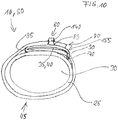
- Figure 10 shows a schematic sectional view through the protective glove 10, 50 shown in Figures 1 to 3 .
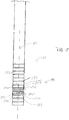
- Figure 11 further shows a detail of a longitudinal cross-section through the end section of the fastening strap 45 shown in Figure 10
- Figure 12 depicts a detail of a longitudinal cross-section through the other end section of the fastening strap 45 illustrated in Figure 10 .
- Figures 4 to 12 will be explained in conjunction with one another.
- the fastening strap 45 is configured as a flat plastic strap, wherein in the area of the first end section 55 a snap fastener 60 is arranged on the broad lateral surface 65 which in Figure 4 corresponds to the upper surface 65 of the fastening strap 45. Furthermore, a engagement element 70 is arranged at the first end 50 of the fastening strap 45 which sticks out from the first end 55 of the fastening strap 45 in the direction of a longitudinal axis 75 of the fastening strap 45.
- a second end 80 of the fastening strap 45 opposite to the first end 55 several apertures 85 are arranged one after the other in the longitudinal direction of the longitudinal axis 75 in the fastening strap 45 as fastening means.
- a T-shaped recess 90 is provided in the fastening strap 45 between the first end 55 and the second end 80.
- a hinge area 95 is provided between the recess 90 and the engagement element 70.
- a labelling area 96 is arranged between the hinge area 95 and the snap fastener 60 acting as a further engagement element, wherein various labels of the fastening strap 45 may be inserted into the labelling area 96 by means of embossing.
- the fastening strap 45 comprises differing colour particles, depending on its length, in order to colour the fastening strap 45 in accordance with the EN 1082 standard.
- the engagement element 70 which is shown in detail in Figure 5 , comprises a head 100 and a longitudinal girder 105 which integrally and by using the same material connects the head 100 to the fastening strap 45.
- the head 100 of the engagement element 70 in this context has a semi-circular shape, is configured on the surface averted 106 from the fastening strap 45 and has a larger width than the longitudinal girder 105, so that the head 100 in conjunction with the longitudinal girder 105 forms a mushroom-shaped engagement element 70.
- the head 100 is configured in such a way that the engagement element 70 may be connected to the recess 90 by means of a positively fitting connection and engages behind the fastening strap 45 in the area of the recess 90.
- the head 100 and/or the recess 90 are in the shape of a triangle, a polygon or an ellipsis.
- the engagement element 70 further comprises a first slant 115 which is arranged at a lateral surface 107 of the head 100 facing the first end 55 of the fastening strap 45.
- the slant 115 is in this context arranged in an inclined manner with regard to the surface 65 of the fastening strap 45.
- the recess 90 has a T-shape and comprises a longitudinal section 120 aligned in longitudinal direction, i.e. in the direction of the longitudinal axis 75, as well as a transverse section 125 aligned in a traverse manner with regard to the longitudinal axis 75.
- the longitudinal section 120 and the traverse section 125 merge in such a way that they form a joint through-hole in the fastening strap 45.
- the longitudinal section 120 is arranged on the side of the transverse section 125 facing the engagement element 70.
- the recess 90 comprises a second slant 130 (cf. Figure 7 ) which, in the same manner as the first slant 115 of the engagement element 70, is slantly arranged with regard to the upper surface 65 of the fastening strap 110.
- the second slant 130 is in this context arranged at the lateral surface 135 adjacent to the engagement element 70, i.e. in a base of the T-shaped recess 90 or, respectively, in the longitudinal section 120.
- the snap fastener 60 extends vertically from the upper surface 65 or, respectively, in a transverse manner with regard to the longitudinal axis 75.
- the snap fastener 60 as well as the fastening strap 45 are formed of an elastomer, preferably a thermoplastic elastomer, in an integral manner and using the same material. Other plastic materials are conceivable, as well, however, it is essential that these have flexible properties in order to allow for the fastening strap 45 to be bent and folded. Due to the integral configuration, the snap fastener 60 is inseparably connected to the fastening strap 45.
- the snap fastener 60 further comprises a catch 140 which is configured circumferentially at the snap fastener 60 and which is arranged at a distance Ab from the snap fastener, the distance Ab corresponding to a thickness D of the fastening strap 45. Between the catch 140 and the fastening strap 45, the snap fastener 60 has a narrowing configuration from the fastening strap in the direction of the catch 140 and thus has a tapered shape in the area of this section 145.
- apertures 85 are arranged which are configured correspondently to the narrowing section 145 of the snap fastener 60. If the snap fastener 60 is inserted into the aperture 85, as shown in Figures 10 and 11 , the snap fastener 60 is partly held by said aperture 85 in the fastening strap 45.
- a peripheral area 146 is configured conically in line with the narrowing section 145 so that the peripheral area 146 contacts the narrowing section 145 in a two-dimensional manner.
- the catch 140 is in this context configured in such a way that a locking surface 150 facing the upper surface 65 rests on the upper surface 65 of the slipped-on second end 80 of the fastening strap 45 if the snap fastener 60 is fully inserted.
- the snap fastener 60 engages behind the fastening strap 45 in the area of the aperture 85 and secures the second end 80 of the fastening 45 at the protective glove 10, 50 in order to prevent it from loosening.
- Transverse forces forces having a vector perpendicular to the upper surface 65 of the fastening strap 45
- Transverse forces forces having a vector perpendicular to the upper surface 65 of the fastening strap 45
- the snap fastener 60 as well as the apertures 85 are configured in a rotationally symmetric manner.
- other cross-sectional shapes such as rectangular, elliptic or polygon-shaped are conceivable.
- the essential feature in this context is that the snap fastener 60 is configured integrally and from the same material as the fastening strap 45 and the aperture 85 is configured as a fastening means in order to hold the snap fastener 60.
- the engagement element 70 is inserted into the recess 90 through the transverse section 125. Securing the fastening strap 45 at the loop 35, 40 is carried out by sliding the head 100 of the engagement element 70 into the longitudinal section 120 via the transverse section 125. Due to the wider configuration of the head 100 with regard to the longitudinal section 120, the head 100 of the engagement element 70 engages behind the fastening strap 45 in the area of the longitudinal section 120 of the recess 90 so that the engagement element 70 is prevented from slipping out of the recess 90.
- the fastening strap 45 forms a loop section 155 which essentially completely grips around the loop 35, 40 in the circumferential direction (cf. Figure 10 ), thus reliably securing the fastening strap 45 at the protective glove 10, 50, even if the snap fastener 60 is not inserted into the aperture 85.
- the contacting in a two-dimensional manner between the engagement element 70 and the fastening strap 45 which is necessary in order to transmit forces is guaranteed by the first slant 115 being configured in such a way that at the head 100 of the engagement element 70 or, respectively, at the recess 90 the first slant 115 contacts the bottom side 165 of the fastening strap 45 in a two-dimensional manner. Furthermore, the second slant 130 is aligned in such a way that when the engagement element 70 is inserted into the recess 90, the first slant 130 contacts the upper surface 65 of the fastening strap 45 or, respectively, of the longitudinal girder 105 in a two-dimensional manner.
- the hinge area 95 is essentially arranged in the middle between the recess 90 and the engagement element 70.
- the hinge area 95 is configured by means of a groove-shaped neck 160 which is guided along the upper surface 65 in a cross-wise manner with regard to the longitudinal axis 75. In this manner, the material of the fastening strap 45 is weakened in the area of the neck 160 which allows for a particularly easy bending or, respectively, folding.
- a width bE of the neck 160 is selected in such a way that the fastening strap 45 may be folded particularly easily and a particularly flat embodiment of the loop section 155 may be provided without pressing the material in the region of the hinge area 95 or plastically deforming it during folding.
- This embodiment further has the advantage that a slanted folding is prevented by the lateral stability of the neck 160.
- the neck 160 is arranged on the bottom surface 165 of the fastening strap.
- the hinge area 95 may of course also be configured by means of two necks 160 bilaterally arranged on the upper surface 65 and the bottom surface 165.
- the neck 160 is arranged on one side or on both sides of a narrow lateral surface 170 of the fastening strap 45.
- the hinge area 95 or the neck 160 are realized by a softly configured outline of the fastening strap 45.
- fastening strap 45 is pre-bent in the region of the hinge area 95 so that the configuration of the loop section 155 is particularly flat.
- the hinge area 95 with a neck 160 shown in the embodiment it is also conceivable that a material differing from the plastic material of the fastening strap is arranged in the hinge area 95, the flexible properties of which are softer than those of the plastic of the fastening strap 45 in the remaining fastening strap 45.
- the two materials of the hinge area 95 and of the fastening strap 45 are moulded in a die e.g. in a two-component injection moulding process in order to produce a fastening strap 45 in one piece.
- the two-component injection moulding process offers the advantage that recesses, which are difficult to clean and e.g. caused by the neck 160, are prevented.
- the fastening strap 45 has a lower thickness D between the hinge area 95 and the engagement element 70 or, respectively, in the loop area 155 than between the hinge area 95 and the second end 80 or, respectively, the engagement element 70 of the fastening strap 45.
- the loop section 155 may be configured in a particularly flat manner.
- the fastening strap 45 is secured at the protective glove 10, 50 by gripping the loop 35, 40 through the loop section 155.
- the protective glove 10, 50 (cf. Figure 10 ) is secured at the wrist 30 by circumferentially guiding the fastening strap 45 around the wrist 30 after slipping the protective glove 10, 50 onto the hand or, respectively, the fingers and the lower arm and by choosing, depending on the circumference of the wrist 30 or of the lower arm, a corresponding aperture 85 through which the snap fastener 60 is inserted. If the snap fastener 60 is inserted completely and if the catch 140 engages, the catch 140 can only be released by means of an increased force so that an involuntary loosening of the fastening strap 45 is prevented.
- the protective glove 10, 50 may be cleaned reliably and thoroughly without dirt accumulating in the region of the fastening strap 45.
- the same may be exchanged simply and without involving any tools.
- the fastening strap might loose components and thus contaminate food.
- FIG 13 shows a perspective view of a further fastening strap 180 and Figure 14 shows a longitudinal cross-section through the fastening strap 180 shown in Figure 13 .
- the fastening strap 180 is essentially configured identically to the fastening strap shown in Figures 1 to 12 .
- the fastening strap 180 comprises, instead of the T-shaped arrangement of a head and a longitudinal girder shown in Figures 1 to 12 , a further snap fastener 185 as a engagement element, the snap fastener 185 being arranged on the bottom surface 165 and thus on the opposite side of the snap fastener 60 of the fastening strap 180.
- the further snap fastener 185 comprises a circumferentially configured catch 190. Between the catch 190 of the further snap fastener 185 and the fastening strap 180, a cylindrical section 195 is arranged at the further snap fastener 185.
- the catch 190 of the further snap fastener 185 comprises a distance Ab which essentially corresponds to the thickness D of the fastening strap 180.
- the end of the further snap fastener 185 facing away from the fastening strap 180 comprises a rounded edge 200.
- the first end 55 of the further fastening strap 180 has a rounded configuration in order to avoid that the fastening strap 180 gets caught when the first end 55 is threaded through the loops 35, 40 of the protective glove 10, 50.
- an aperture 205 configured correspondently to the further snap fastener 185 is provided in the fastening strap 180 as a fastening means.
- the aperture 205 is configured cylindrically as a through-hole.
- the bore hole 205 on the bottom surface of the fastening strap 180 is slanted by means of a bevel 210.
- Figure 15 depicts a schematic cross-section through the protective glove 10, 50 shown in Figures 1 to 13 comprising the fastening strap 180 depicted in Figures 13 and 14 .
- the fastening strap 180 also comprises the loop section 155 which is configured by guiding the first end 55 through the loop 35, 40 and bending it. The bending process is facilitated by the hinge area 95.
- the further snap fastener 185 is inserted into the aperture 205.
- the rounded edge 200 at the further snap fastener 185 facilitates the insertion of the further snap fastener 185 into the aperture 205.
- inserting the further snap fastener 185 is facilitated by means of a bevel 210 at the aperture 205.
- the catch 190 of the further snap fastener 185 prevents an independent loosening of the loop section 155 by the fact that, when the further snap fastener 185 is completely inserted, a locking area 196 arranged on the bottom side of the catch 190 contacts the upper surface 65 of the fastening strap 180. In doing so, the catch 190 of the further snap fastener 185 engages behind the further fastening strap 180 in the area of the aperture 205, so that the fastening strap 180 is secured at the loop 35, 40.
- the protective glove 10, 50 is secured at the wrist or, respectively, at the arm by circumferentially guiding the fastening strap 180 around the protective glove 10, 50 after threading through the loop section 155 and the snap fastener engages behind the aperture 85 as described above, thus preventing an independent loosening of the second end 80 of the fastening strap 180 at the protective glove 10, 50.
- Figure 16 shows a perspective partial view of a further alternative embodiment of the fastening strap shown in Figure 8 .
- an alternative snap fastener 215 is provided at the alternative fastening strap 211 as a further engagement element, which is configured similarly to the snap fastener shown in Figure 8 .
- the snap fastener 215 comprises a rectangular configuration comprising a circumferentially arranged catch 220. As shown in Figure 8 , the narrowing section 145 is arranged between the catch 220 and the upper surface 65 of the fastening strap 211.
- the snap fastener 215 comprises a larger extension with regard to its width at the fastening strap 211, i.e. in a cross-wise manner to the longitudinal direction of the fastening strap 211, than the snap fastener shown in Figure 8 .
- the catch 220 comprises a locking area 225 arranged opposite to the upper surface 65 of the fastening strap 211.
- the catch 220 is completely circumferentially arranged around the rectangular body of the snap fastener 215.
- the catch 220 is only arranged on one side or only in partial areas of one side of the snap fastener 215.
- the catch 220 is at least provided at the sides of the snap fastener 215 which cross the longitudinal axis 75 of the fastening strap 211. Due to the rectangular embodiment, the alternative snap fastener 215 may be configured in a slimmer and more compact manner than the snap fastener shown in Figure 8 , while maintaining the same force-transmitting properties.
- FIG 17 is a perspective partial view of the fastening strap shown in Figure 16 .
- the fastening strap 211 comprises several apertures 230 arranged along the longitudinal axis 75, the apertures 230 being configured correspondently to the snap fastener 215 depicted in Figure 16 and having an essentially rectangular cross-section.
- the rectangular cross-section of the apertures 230 respectively comprises rounded edges 240, thus preventing the fastening strap 211 in the corner region 235 of the apertures 230 from tearing.
- the fastening strap 211 may be taken from the injection mould in a simple manner after injection moulding.
- the snap fastener 215 is inserted into the aperture 230 until the bottom surface 165 of the fastening strap 211 contactss the upper surface 65 of the fastening strap 211 in the area of the snap fastener 215 or, respectively, until the snap fastener has fully engaged through the fastening strap 211 and the locking area 225 contacts the upper surface 65 of the fastening strap 211 in the region of the second end 80 of the fastening strap 211.
- a number of apertures 230 may be provided at the second end 80 of the fastening strap 211 which is larger compared to the cylindrical configuration of the apertures so that a more smooth and almost continuous adjustment of the fastening strap 211 to the individual wrist or, respectively, arm circumference of the user of the protective glove 10, 50 may be provided.
- Figure 18 shows partial top view onto a further alternative embodiment of a fastening strap 250.
- the further end 80 of the alternative fastening strap 250 shown in Figure 18 may be combined with the various embodiments of the first end 55 of the fastening straps 45, 180, 211 depicted in conjunction with Figures 4 to 17 .
- the further alternative fastening strap 250 comprises several ribs 255 arranged transversely with regard to the longitudinal axis 75 at an identical distance with regard to one another, the ribs 255 protruding from the upper surface 65 of the fastening strap 250 as bumps.
- a snap fastener buckle 260 is provided in the area of the ribs 255 of the further end 80 of the fastening strap 250.
- the snap fastener buckle 260 comprises a bottom 265 which is arranged above the upper surface 65 of the fastening strap 250.
- several bent clip elements 270 are provided on the side of the snap fastener buckle 260, which laterally grip the fastening strap 255 and thus fix the snap fastener buckle 260 to the fastening strap 250.
- two slit-like recesses 275, 280 are provided at the snap fastener buckle 260.
- the recesses 275, 280 are arranged in the bottom 265 of the snap fastener buckle 260 in such a way that when the snap fastener buckle 260 engages, a rib 255 of the fastening strap 250 respectively engages in a recess 275, 280 of the snap fastener buckle 260.
- the snap fastener buckle 260 further comprises a receiving opening 285 which is arranged approximately in the middle and is configured with a circular shape corresponding to the snap fastener 60 shown in Figures 4 and 5 .
- the receiving opening 285 may also have a different shape, e.g. a polygon, an ellipsis or a rectangle.
- the receiving opening 285 is configured to hold the snap fastener 60 shown in Figures 4 and 5 in a similar manner as explained in conjunction with Figure 10 in order to tie the fastening strap 250 and to fix the protective glove 10, 50 to the wrist 30 or, respectively, to the arm.
- the receiving opening 285 has a rectangular configuration corresponding to the snap fastener 215 depicted in Figure 16 , the snap fastener 215 is held by the receiving opening 285, as described above.
- apertures 85, 230 may also be arranged in two or several rows, if the width of the fastening strap 45, 180, 211 permits.
- a corresponding number of rows of snap fasteners 60, 215 would be provided, as well.
- the snap fasteners 60, 215 are held by the apertures 85, 230.
- thermoplastic elastomer as a plastic material for the fastening strap 45, 180, 211, 250 and the snap fastener 60, 185, 215, other elastic plastic materials are, of course, conceivable. However, it is essential that these plastic materials are suitable for use in the food industry.
- the snap fastener 60, 185, 215 comprises a plastic material different from that of the fastening strap 45, 180, 211, 250 and which is e.g. harder than the plastic of the fastening strap 45, 180, 211, 250.
- the snap fastener 60, 185, 215 and the fastening strap 45, 180, 211, 250 may independently from each other be adjusted to the respective mechanical strains.
- the snap fastener 60, 185, 215 and the fastening strap 45, 180, 211, 250 may be manufactured in a two-component injection moulding process so that the snap fastener 60, 185, 215 and the fastening strap 45, 180, 211, 250 are manufactured in one piece with each other, thus reliably preventing a loss of the snap fastener 60, 185, 215. Moreover, dirt accumulations at the fastening strap 45, 180, 215 may be avoided.
- the protective closing 10, 50 may be at least one of the following types of clothing: as a glove 10, particularly as a five-finger glove, as a glove 50 with a protective sleeve, particularly a protection for the entire or part of the arm, as a protective sleeve piece, as a protective leg piece, as a shirt, as a tunic with/without sleeves, as a pair of trousers, as a hood for protecting the head or the nape of the neck, as an apron, as a bolero with/without sleeves.
- the essential feature is that the above-described fastening strap 45, 180, 211, 250 grips a loop 35, 40 of the protective clothing 10, 50 by means of a loop section 155 so that the fastening strap 45, 180, 211, 250 is fixed to the protective clothing 10, 50 even if the fastening strap 45, 180, 211, 250 is open.
Landscapes
- Engineering & Computer Science (AREA)
- Textile Engineering (AREA)
- Health & Medical Sciences (AREA)
- General Health & Medical Sciences (AREA)
- Physical Education & Sports Medicine (AREA)
- Heart & Thoracic Surgery (AREA)
- Gloves (AREA)
- Clamps And Clips (AREA)
- Professional, Industrial, Or Sporting Protective Garments (AREA)
- Package Frames And Binding Bands (AREA)
- Purses, Travelling Bags, Baskets, Or Suitcases (AREA)
Description
- The present invention relates to a fastening strap for fastening to loop formed of a metal-ring mesh of protective clothing, as well as to protective clothing, the fastening strap comprising at least one engagement element as well as a recess configured correspondently to the engagement element, the engagement element and the recess engaging with each other and configuring a loop section configured to grip the loop of the protective clothing and to fasten the fastening strap to the loop of the protective clothing.
-
US 2004/025223 A1 discloses protection glove made of coat of mail, i.e. formed of a latticework of interlaced metallic rings. -
EP 1 919 314 B1 - The above-mentioned protective glove may also be manufactured with a gauntlet consisting of the metal-ring mesh, the gauntlet comprising two fastening straps in this embodiment which are arranged in an area around the wrist of the user and at a rear end of the gauntlet in order to secure the protective glove in its position at the hand or the arm.
- It is a disadvantage of the known protective glove that for fastening the fastening strap, two additional metal components are required, i.e. the snap fastener itself and the snap fastener buckle. Both are manufactured in a complex manner from high-quality materials in order to meet the demands of high hygienic standards, e.g. in the meat-processing industry.
- The object underlying the present invention is to improve a fastening strap for protective clothing consisting of a metal-ring mesh of the type referred to above in such a way that the fastening strap is configured hygienically and may be produced in a simple manner. A further object is to reduce the danger of losing the fastening strap.
- This object is solved by means of protective clothing comprising a fastening strap with the features of
claim 1. Further advantageous embodiments of the invention are indicated in the dependent claims. - The protective clothing according to the invention consisting of a metal-ring mesh comprises a fastening strap and at least one loop formed of the metal-ring mesh. The fastening strap comprises at least a engagement element and a recess configured correspondently to the engagement element. The engagement element and the recess engage with each other und form a loop section which is configured to grip the loop of the protective clothing and to fasten the fastening strap to the loop of the protective clothing.
- This embodiment has the advantage that a loss of the fastening strap due to the fastening strap slipping out of the loop of the protective clothing may be prevented. Furthermore, it is particularly easy to exchange a defect fastening strap of the protective clothing.
- In a further embodiment, at least one further engagement element and a fastening means configured correspondently to the further engagement element is provided at the fastening strap, the fastening means being configured to at least partially hold the further engagement element. In this way, the protective clothing may easily be secured against slipping e.g. at the wrist or arm, or even at an upper body of the user of the protective clothing by means of the fastening strap.
- In a further embodiment, the fastening strap and the further engagement element are made of a plastic material. By using plastic as a material for the fastening strap and for the further engagement element, the weight of protective clothing may be rendered lighter.
- Furthermore, an integral configuration of the fastening strap together with the further engagement element prevents dirt from accumulating at the fastening strap, making the fastening strap more hygienic than known fastening straps; moreover, the fastening strap may be cleaned reliably and easily together with the protective clothing. Moreover, a loss of the further engagement element, particularly of a snap fastener, is reliably prevented by the integral configuration.
- A further advantage of an integral configuration of the fastening strap and the further engagement element using the same material is that the fastening strap and the further engagement element may be inexpensively manufactured in one single manufacturing step by means of injection moulding.
- In a further embodiment, the further engagement element comprises a catch configured to engage behind the fastening means of the fastening strap. In this manner, the fastening strap may simply be tied down, thus securing the protective clothing as well as the fastening strap itself.
- In a further embodiment, the catch is circumferentially configured at the further engagement element and preferably arranged at the further engagement element at a distance corresponding to a thickness of the fastening strap. In this manner, a particularly secure fastening of the fastening strap at the further engagement element is provided in order to prevent an involuntary loosening.
- In a further embodiment, the further engagement element comprises a section between the catch and the fastening strap, the section having a narrowing configuration in the direction of the catch. This facilitates inserting the further engagement element into the fastening means or, respectively, into the aperture of the fastening strap.
- In a further embodiment, the fastening means is configured as an aperture and as a cone in such a way that the narrowing section of the further engagement element contacts the aperture in a two-dimensional manner. In this manner, the further engagement element may be more easily inserted into the aperture and at the same time forces acting upon the further engagement element may reliably be transferred to the aperture and vice versa due to the further engagement element contacting the aperture in a two-dimensional manner.
- In this context, it is particularly advantageous if the engagement element has the shape of a mushroom or of a T, and/or if the recess has a T-shape or if the engagement element is configured as a snap fastener and the recess as a bore hole.
- In a further embodiment, the engagement element comprises a first slant which is arranged at a surface of the engagement element facing the fastening strap and configured in such a way that when the engagement element engages with the recess, the first slant of the engagement element contacts a first counter surface of the fastening strap correspondently associated with the first slant in a two-dimensional manner and/or the recess comprises a second slant which is arranged in such a way that when the engagement element engages with the recess, the second slant contacts a counter surface of the of the engagement element correspondently associated with the second slant in a two-dimensional manner. In this manner, a wide support area of the engagement element is provided in the area of the recess in order to optimally transfer a force between the engagement element and the fastening strap.
- The arrangement is particularly advantageous when the further engagement element is arranged at the fastening strap between the recess and the engagement element. In this manner it is guaranteed that the further engagement element is on the outer side of the protective clothing and thus more easily accessible for the user of the protective clothing in order to fasten the protective clothing e.g. to the arm by means of the fastening strap.
- In a further embodiment, the fastening means is arranged at a section of the fastening strap arranged at an end opposite to the engagement element. The arrangement allows for a short configuration of the fastening strap which may consequently be manufactured inexpensively and with a low weight due to a low material demand.
- The folding of the fastening strap in the area of the loop section can be supported by a hinge area being provided at the fastening strap between the recess and the engagement element.
- The hinge section of the fastening strap may easily be configured by means of a neck in the fastening strap or by choosing a material differing from the plastic material of the fastening strap and having flexible properties.
- In a further embodiment, the fastening strap comprises a lower thickness between the engagement element and the hinge area than between the hinge area and the end of the fastening strap opposite to the engagement element. In this manner, the fastening strap may be folded particularly flatly in the loop section.
- In a further embodiment, the plastic material of the further engagement element and of the fastening strap is an elastomer, particularly a thermoplastic elastomer.
- According to the invention, the protective clothing consists of a metal-ring mesh comprising an above-described fastening strap and at least one loop formed of the metal-ring mesh. The loop section is configured to grip around the loop of the protective clothing and to fasten the fastening strap to the loop of the protective clothing, losing the fastening strap when it is open may thus be prevented.
- In a further embodiment, the above-described protective clothing may advantageously be configured as at least one of the following types of clothing: as a glove, particularly as a five-finger glove, as a glove with a protective sleeve, particularly a protection for the entire or part of the arm, as a protective sleeve piece, as a protective leg piece, as a protective shirt, as a protective tunic with/without sleeves, as a pair of protective trousers, as a protective hood, as a protective apron, as a bolero with/without sleeves.
- In the following, the present invention will be explained in more detail in conjunction with the accompanying drawings. In this context, identical components have identical reference numerals.
-
Figure 1 shows a perspective rear view of a protective glove comprising a gauntlet; -
Figure 2 depicts a front view of the protective glove shown inFigure 1 ; -
Figure 3 shows a perspective rear view of a further protective glove; -
Figure 4 is a perspective view of a fastening strap of the protective glove shown inFigures 1 to 3 ; -
Figure 5 shows a perspective view of a detail of the fastening strap shown inFigure 4 ; -
Figure 6 depicts a detail marked inFigure 5 and showing a longitudinal cross-section through the fastening strap shown inFigures 4 and5 ; -
Figure 7 shows a further detail marked inFigure 5 and showing a longitudinal cross-section through the fastening strap shown inFigures 4 and5 ; -
Figure 8 shows a perspective partial view of an end section of the fastening strap shown inFigure 4 ; -
Figure 9 depicts a perspective partial view of a further end section of the fastening strap shown inFigures 4 and5 ; -
Figure 10 shows a schematic cross-sectional view through the protective glove shown inFigures 1 to 3 ; -
Figure 11 illustrates a detail of the longitudinal cross-section through the end section of the fastening strap shown inFigure 10 ; -
Figure 12 depicts a detail of a longitudinal cross-section through the further end section of the fastening strap shown inFigure 10 ; -
Figure 13 shows a perspective view of an alternative fastening strap; -
Figure 14 shows a longitudinal cross-section through the alternative fastening strap shown inFigure 13 ; -
Figure 15 shows a schematic cross-section through the protective glove depicted inFigures 1 to 3 comprising the fastening strap shown inFigures 13 or, respectively, 14; -
Figure 16 depicts a perspective partial view of an alternative embodiment of the fastening strap shown inFigure 8 ; -
Figure 17 illustrates a perspective partial view of the fastening strap shown inFigure 16 ; and -
Figure 18 shows a partial top view of a further alternative embodiment of a fastening strap. -
Figure 1 shows a perspective rear view of a protective glove 10 as a piece of protective clothing comprising agauntlet 15, andFigure 2 depicts a front view of the protective glove shown inFigure 1 which consists of a metal-ring mesh 26 from the finger tips 20 down to therear rim 25 of thegauntlet 15. The protective gloves 10 shown inFigures 1 and2 in this context serve as personal protective clothing of a user in order to protect the user's body against the penetration of pointy and/or sharp objects, particularly knives. - In the area of the
wrist 30 of the protective glove's 10 user, severalfirst loops 35 made of the metal-ring mesh 26 are provided. At arear rim 25 of thegauntlet 15, severalsecond loops 40 made of the metal-ring mesh 26 are provided. Depending on the breadth of thewrist 30 or, respectively, of a lower arm in the area of therear rim 25, e.g. threeloops wrist 30. Of course, a different number ofloops wrist 30 or, respectively, at therear rim 25. - The
loops fastening strap loops gauntlet 15, by means of a metal-ring mesh having a strap-like configuration and the dimensions of theloops ring mesh 26 being linked with the underlying metal-ring mesh 26. - The
first loops 35 as well as thesecond loops 40 each accommodate afastening strap fastening strap Figures 4 to 18 . Thefastening strap - It is to be noted that the
gauntlet 15 may not only be configured for protecting the lower arm in the form of a protective half-sleeve, but also as a protection for the entire arm, so that thegauntlet 15 covers an arm over its entire length. Thegauntlet 15 may also be configured as protective arm piece or protective leg piece, so that thegauntlet 15 exclusively consists of a metal-ring mesh 26 between thefirst loop 35 and thesecond loop 40 and the fastening straps 45, 180 fastened thereto. -
Figure 3 shows a perspective view of a furtherprotective glove 50 as protective clothing in an embodiment without the gauntlet shown inFigures 1 and2 , so that theprotective glove 50 may be easily slipped on if thefastening strap protective glove 50 as well as the protective glove shown inFigures 1 and2 comprises a metal-ring mesh 26 and severalfirst loops 35 arranged at thewrist 30, through which, as shown inFigures 1 and2 , thefastening strap 45 is threaded. In this embodiment, thefastening strap 45 serves to fix theprotective glove 50 to thewrist 30 of the user's hand and prevents theprotective glove 50 from slipping off thewrist 30. - In
Figures 1 to 3 , the protective glove 10 is a five-finger glove. Of course, a configuration as mitten or three-finger glove or comprising a different number of fingers is conceivable, as well. -
Figure 4 shows a perspective view of thefastening strap 45 of theprotective gloves 10, 50 shown inFigures 1 to 3 .Figure 5 shows a perspective view of a detail of thefastening strap 45 shown inFigure 4 andFigure 6 shows a detail A marked inFigure 5 of a longitudinal cross-section through thefastening strap 45.Figure 7 shows a further detail B marked inFigure 5 of a longitudinal cross-section through thefastening strap 45.Figures 8 and9 show further perspective views of further details of thefastening strap 45 shown inFigure 4 , andFigure 10 shows a schematic sectional view through theprotective glove 10, 50 shown inFigures 1 to 3 .Figure 11 further shows a detail of a longitudinal cross-section through the end section of thefastening strap 45 shown inFigure 10 , andFigure 12 depicts a detail of a longitudinal cross-section through the other end section of thefastening strap 45 illustrated inFigure 10 . In the following,Figures 4 to 12 will be explained in conjunction with one another. - The
fastening strap 45 is configured as a flat plastic strap, wherein in the area of the first end section 55 asnap fastener 60 is arranged on the broadlateral surface 65 which inFigure 4 corresponds to theupper surface 65 of thefastening strap 45. Furthermore, aengagement element 70 is arranged at thefirst end 50 of thefastening strap 45 which sticks out from thefirst end 55 of thefastening strap 45 in the direction of alongitudinal axis 75 of thefastening strap 45. - At a
second end 80 of thefastening strap 45 opposite to thefirst end 55,several apertures 85 are arranged one after the other in the longitudinal direction of thelongitudinal axis 75 in thefastening strap 45 as fastening means. Moreover, a T-shapedrecess 90 is provided in thefastening strap 45 between thefirst end 55 and thesecond end 80. Furthermore, ahinge area 95 is provided between therecess 90 and theengagement element 70. Moreover, alabelling area 96 is arranged between thehinge area 95 and thesnap fastener 60 acting as a further engagement element, wherein various labels of thefastening strap 45 may be inserted into thelabelling area 96 by means of embossing. It is thus conceivable, as shown inFigure 5 , to insert the lettering "hand" in thelabelling area 96 in order to identify thefastening strap 45 which is provided for thefirst loops 35 arranged at thewrist 30. By means of this, e.g. different lengths of fastening straps 45 may be labelled. Thus, e.g. afastening strap 45 which has a shorter configuration may be provided with the label "hand", as shown inFigure 5 , and a non-depicted, longer fastening strap may e.g. be provided with the label "arm". - As an alternative, it is conceivable as well that the
fastening strap 45 comprises differing colour particles, depending on its length, in order to colour thefastening strap 45 in accordance with the EN 1082 standard. - The
engagement element 70, which is shown in detail inFigure 5 , comprises ahead 100 and a longitudinal girder 105 which integrally and by using the same material connects thehead 100 to thefastening strap 45. Thehead 100 of theengagement element 70 in this context has a semi-circular shape, is configured on the surface averted 106 from thefastening strap 45 and has a larger width than the longitudinal girder 105, so that thehead 100 in conjunction with the longitudinal girder 105 forms a mushroom-shapedengagement element 70. - Alternatively, it is also conceivable that the
head 100 is configured in such a way that theengagement element 70 may be connected to therecess 90 by means of a positively fitting connection and engages behind thefastening strap 45 in the area of therecess 90. In this context, it is particularly conceivable that thehead 100 and/or therecess 90 are in the shape of a triangle, a polygon or an ellipsis. - The
engagement element 70 further comprises afirst slant 115 which is arranged at a lateral surface 107 of thehead 100 facing thefirst end 55 of thefastening strap 45. Theslant 115 is in this context arranged in an inclined manner with regard to thesurface 65 of thefastening strap 45. - The
recess 90 has a T-shape and comprises alongitudinal section 120 aligned in longitudinal direction, i.e. in the direction of thelongitudinal axis 75, as well as atransverse section 125 aligned in a traverse manner with regard to thelongitudinal axis 75. In this context, thelongitudinal section 120 and thetraverse section 125 merge in such a way that they form a joint through-hole in thefastening strap 45. Thereby, thelongitudinal section 120 is arranged on the side of thetransverse section 125 facing theengagement element 70. - The
recess 90 comprises a second slant 130 (cf.Figure 7 ) which, in the same manner as thefirst slant 115 of theengagement element 70, is slantly arranged with regard to theupper surface 65 of thefastening strap 110. Thesecond slant 130 is in this context arranged at thelateral surface 135 adjacent to theengagement element 70, i.e. in a base of the T-shapedrecess 90 or, respectively, in thelongitudinal section 120. - The
snap fastener 60, as shown in detail inFigure 8 , extends vertically from theupper surface 65 or, respectively, in a transverse manner with regard to thelongitudinal axis 75. Thesnap fastener 60 as well as thefastening strap 45 are formed of an elastomer, preferably a thermoplastic elastomer, in an integral manner and using the same material. Other plastic materials are conceivable, as well, however, it is essential that these have flexible properties in order to allow for thefastening strap 45 to be bent and folded. Due to the integral configuration, thesnap fastener 60 is inseparably connected to thefastening strap 45. Thesnap fastener 60 further comprises acatch 140 which is configured circumferentially at thesnap fastener 60 and which is arranged at a distance Ab from the snap fastener, the distance Ab corresponding to a thickness D of thefastening strap 45. Between thecatch 140 and thefastening strap 45, thesnap fastener 60 has a narrowing configuration from the fastening strap in the direction of thecatch 140 and thus has a tapered shape in the area of thissection 145. - At the
second end 80 of thefastening strap 45 opposite to theengagement element 70,several apertures 85, as shown in an enlarged manner inFigure 9 , are arranged which are configured correspondently to thenarrowing section 145 of thesnap fastener 60. If thesnap fastener 60 is inserted into theaperture 85, as shown inFigures 10 and11 , thesnap fastener 60 is partly held by saidaperture 85 in thefastening strap 45. In order to enlarge the contact surface between the narrowingsection 145 of thesnap fastener 60 and theaperture 85, a peripheral area 146 is configured conically in line with thenarrowing section 145 so that the peripheral area 146 contacts thenarrowing section 145 in a two-dimensional manner. - Due to the corresponding configuration of the peripheral area 146 of the
aperture 85 with regard to thenarrowing section 145, these components in an assembled state contact each other in a two-dimensional manner, so that forces acting in the direction of thelongitudinal axis 75, e.g. resulting from the tensile strain of thefastening strap 45 when fixing theprotective glove 10, 50, can be reliably transferred from thesnap fastener 60 to theaperture 85. This embodiment of thesnap fastener 60 or, respectively, of theaperture 85 together with thecatch 140 further prevents thesnap fastener 60 from slipping out of theaperture 85. Moreover, inserting or, respectively, pulling through thesnap fastener 60 into/through theaperture 85 is facilitated by the cone-shaped configuration of theaperture 85. - The
catch 140 is in this context configured in such a way that a lockingsurface 150 facing theupper surface 65 rests on theupper surface 65 of the slipped-onsecond end 80 of thefastening strap 45 if thesnap fastener 60 is fully inserted. As a result, thesnap fastener 60 engages behind thefastening strap 45 in the area of theaperture 85 and secures thesecond end 80 of thefastening 45 at theprotective glove 10, 50 in order to prevent it from loosening. Transverse forces (forces having a vector perpendicular to theupper surface 65 of the fastening strap 45) are transmitted in the direction of thesnap fastener 140 by means of thecatch 140 due to the interlock of thefastening strap 45 at thesnap fastener 60 and in the opposite direction by means of thenarrowing section 145 and the peripheral area of theaperture 85. - In the embodiment, the
snap fastener 60 as well as theapertures 85 are configured in a rotationally symmetric manner. Of course, other cross-sectional shapes such as rectangular, elliptic or polygon-shaped are conceivable. The essential feature in this context, however, is that thesnap fastener 60 is configured integrally and from the same material as thefastening strap 45 and theaperture 85 is configured as a fastening means in order to hold thesnap fastener 60. - In order to fix the
fastening strap 45 to theprotective glove 20, 50, as shown inFigures 10 and11 , theengagement element 70 is inserted into therecess 90 through thetransverse section 125. Securing thefastening strap 45 at theloop head 100 of theengagement element 70 into thelongitudinal section 120 via thetransverse section 125. Due to the wider configuration of thehead 100 with regard to thelongitudinal section 120, thehead 100 of theengagement element 70 engages behind thefastening strap 45 in the area of thelongitudinal section 120 of therecess 90 so that theengagement element 70 is prevented from slipping out of therecess 90. - When the
engagement element 70 engages with therecess 90, thefastening strap 45 forms aloop section 155 which essentially completely grips around theloop Figure 10 ), thus reliably securing thefastening strap 45 at theprotective glove 10, 50, even if thesnap fastener 60 is not inserted into theaperture 85. - The contacting in a two-dimensional manner between the
engagement element 70 and thefastening strap 45 which is necessary in order to transmit forces is guaranteed by thefirst slant 115 being configured in such a way that at thehead 100 of theengagement element 70 or, respectively, at therecess 90 thefirst slant 115 contacts thebottom side 165 of thefastening strap 45 in a two-dimensional manner. Furthermore, thesecond slant 130 is aligned in such a way that when theengagement element 70 is inserted into therecess 90, thefirst slant 130 contacts theupper surface 65 of thefastening strap 45 or, respectively, of the longitudinal girder 105 in a two-dimensional manner. - In order to support the folding when inserting the
engagement element 70 into therecess 90 in theloop section 155 and in order to provide as flat a configuration of theloop section 155 around theloop hinge area 95 is essentially arranged in the middle between therecess 90 and theengagement element 70. In the embodiment, thehinge area 95 is configured by means of a groove-shapedneck 160 which is guided along theupper surface 65 in a cross-wise manner with regard to thelongitudinal axis 75. In this manner, the material of thefastening strap 45 is weakened in the area of theneck 160 which allows for a particularly easy bending or, respectively, folding. In the embodiment, a width bE of theneck 160 is selected in such a way that thefastening strap 45 may be folded particularly easily and a particularly flat embodiment of theloop section 155 may be provided without pressing the material in the region of thehinge area 95 or plastically deforming it during folding. This embodiment further has the advantage that a slanted folding is prevented by the lateral stability of theneck 160. - Alternatively, it is conceivable that the
neck 160 is arranged on thebottom surface 165 of the fastening strap. Differing from the depiction in Figures, thehinge area 95 may of course also be configured by means of twonecks 160 bilaterally arranged on theupper surface 65 and thebottom surface 165. As an alternative, it is conceivable that theneck 160 is arranged on one side or on both sides of a narrow lateral surface 170 of thefastening strap 45. Of course, it is also conceivable that thehinge area 95 or theneck 160 are realized by a softly configured outline of thefastening strap 45. - It is also conceivable that the
fastening strap 45 is pre-bent in the region of thehinge area 95 so that the configuration of theloop section 155 is particularly flat. - As an alternative or in addition to the
hinge area 95 with aneck 160 shown in the embodiment, it is also conceivable that a material differing from the plastic material of the fastening strap is arranged in thehinge area 95, the flexible properties of which are softer than those of the plastic of thefastening strap 45 in the remainingfastening strap 45. In this context, it is particularly advantageous if the two materials of thehinge area 95 and of thefastening strap 45 are moulded in a die e.g. in a two-component injection moulding process in order to produce afastening strap 45 in one piece. The two-component injection moulding process offers the advantage that recesses, which are difficult to clean and e.g. caused by theneck 160, are prevented. - It is also conceivable that the
fastening strap 45 has a lower thickness D between thehinge area 95 and theengagement element 70 or, respectively, in theloop area 155 than between thehinge area 95 and thesecond end 80 or, respectively, theengagement element 70 of thefastening strap 45. In this manner, theloop section 155 may be configured in a particularly flat manner. - As mentioned above, the
fastening strap 45 is secured at theprotective glove 10, 50 by gripping theloop loop section 155. The protective glove 10, 50 (cf.Figure 10 ) is secured at thewrist 30 by circumferentially guiding thefastening strap 45 around thewrist 30 after slipping theprotective glove 10, 50 onto the hand or, respectively, the fingers and the lower arm and by choosing, depending on the circumference of thewrist 30 or of the lower arm, a correspondingaperture 85 through which thesnap fastener 60 is inserted. If thesnap fastener 60 is inserted completely and if thecatch 140 engages, thecatch 140 can only be released by means of an increased force so that an involuntary loosening of thefastening strap 45 is prevented. - Due to the integral configuration of the
fastening strap 45 with the same material, theprotective glove 10, 50 may be cleaned reliably and thoroughly without dirt accumulating in the region of thefastening strap 45. In the same manner, in the case of a wearout of thefastening strap 45, the same may be exchanged simply and without involving any tools. Furthermore, it is not possible that the fastening strap might loose components and thus contaminate food. -
Figure 13 shows a perspective view of afurther fastening strap 180 andFigure 14 shows a longitudinal cross-section through thefastening strap 180 shown inFigure 13 . Thefastening strap 180 is essentially configured identically to the fastening strap shown inFigures 1 to 12 . Differing from the embodiment shown inFigures 1 to 12 , thefastening strap 180 comprises, instead of the T-shaped arrangement of a head and a longitudinal girder shown inFigures 1 to 12 , afurther snap fastener 185 as a engagement element, thesnap fastener 185 being arranged on thebottom surface 165 and thus on the opposite side of thesnap fastener 60 of thefastening strap 180. In this context, thefurther snap fastener 185 comprises a circumferentially configuredcatch 190. Between thecatch 190 of thefurther snap fastener 185 and thefastening strap 180, acylindrical section 195 is arranged at thefurther snap fastener 185. - The
catch 190 of thefurther snap fastener 185 comprises a distance Ab which essentially corresponds to the thickness D of thefastening strap 180. The end of thefurther snap fastener 185 facing away from thefastening strap 180 comprises arounded edge 200. Furthermore, thefirst end 55 of thefurther fastening strap 180 has a rounded configuration in order to avoid that thefastening strap 180 gets caught when thefirst end 55 is threaded through theloops protective glove 10, 50. - In addition to the
further snap fastener 185, anaperture 205 configured correspondently to thefurther snap fastener 185 is provided in thefastening strap 180 as a fastening means. Thereby, theaperture 205 is configured cylindrically as a through-hole. Furthermore, thebore hole 205 on the bottom surface of thefastening strap 180 is slanted by means of abevel 210. -
Figure 15 depicts a schematic cross-section through theprotective glove 10, 50 shown inFigures 1 to 13 comprising thefastening strap 180 depicted inFigures 13 and14 . Thefastening strap 180 also comprises theloop section 155 which is configured by guiding thefirst end 55 through theloop hinge area 95. In order to secure thefastening strap 180 at theloop 35 40, thefurther snap fastener 185 is inserted into theaperture 205. Therounded edge 200 at thefurther snap fastener 185 facilitates the insertion of thefurther snap fastener 185 into theaperture 205. In the same way, inserting thefurther snap fastener 185 is facilitated by means of abevel 210 at theaperture 205. Thecatch 190 of thefurther snap fastener 185 prevents an independent loosening of theloop section 155 by the fact that, when thefurther snap fastener 185 is completely inserted, alocking area 196 arranged on the bottom side of thecatch 190 contacts theupper surface 65 of thefastening strap 180. In doing so, thecatch 190 of thefurther snap fastener 185 engages behind thefurther fastening strap 180 in the area of theaperture 205, so that thefastening strap 180 is secured at theloop Figure 10 , theprotective glove 10, 50 is secured at the wrist or, respectively, at the arm by circumferentially guiding thefastening strap 180 around theprotective glove 10, 50 after threading through theloop section 155 and the snap fastener engages behind theaperture 85 as described above, thus preventing an independent loosening of thesecond end 80 of thefastening strap 180 at theprotective glove 10, 50. -
Figure 16 shows a perspective partial view of a further alternative embodiment of the fastening strap shown inFigure 8 . Thereby, analternative snap fastener 215 is provided at thealternative fastening strap 211 as a further engagement element, which is configured similarly to the snap fastener shown inFigure 8 . - In essence, the
snap fastener 215 comprises a rectangular configuration comprising a circumferentially arrangedcatch 220. As shown inFigure 8 , thenarrowing section 145 is arranged between thecatch 220 and theupper surface 65 of thefastening strap 211. In this context, thesnap fastener 215 comprises a larger extension with regard to its width at thefastening strap 211, i.e. in a cross-wise manner to the longitudinal direction of thefastening strap 211, than the snap fastener shown inFigure 8 . In this context, thecatch 220 comprises alocking area 225 arranged opposite to theupper surface 65 of thefastening strap 211. In the embodiment, thecatch 220 is completely circumferentially arranged around the rectangular body of thesnap fastener 215. Of course, it is also conceivable that thecatch 220 is only arranged on one side or only in partial areas of one side of thesnap fastener 215. However, it is advantageous if thecatch 220 is at least provided at the sides of thesnap fastener 215 which cross thelongitudinal axis 75 of thefastening strap 211. Due to the rectangular embodiment, thealternative snap fastener 215 may be configured in a slimmer and more compact manner than the snap fastener shown inFigure 8 , while maintaining the same force-transmitting properties. -
Figure 17 is a perspective partial view of the fastening strap shown inFigure 16 . Thefastening strap 211 comprisesseveral apertures 230 arranged along thelongitudinal axis 75, theapertures 230 being configured correspondently to thesnap fastener 215 depicted inFigure 16 and having an essentially rectangular cross-section. In acorner area 235, the rectangular cross-section of theapertures 230 respectively comprises roundededges 240, thus preventing thefastening strap 211 in thecorner region 235 of theapertures 230 from tearing. Furthermore, thefastening strap 211 may be taken from the injection mould in a simple manner after injection moulding. - In order to fix the
protective glove 10, 50 to thewrist 30 or, respectively, to the arm, thesnap fastener 215 is inserted into theaperture 230 until thebottom surface 165 of thefastening strap 211 contactss theupper surface 65 of thefastening strap 211 in the area of thesnap fastener 215 or, respectively, until the snap fastener has fully engaged through thefastening strap 211 and thelocking area 225 contacts theupper surface 65 of thefastening strap 211 in the region of thesecond end 80 of thefastening strap 211. Due to the rectangular configuration of thesnap fastener 215 or, respectively, the corresponding configuration of theapertures 230 with regard to thesnap fastener 215, a number ofapertures 230 may be provided at thesecond end 80 of thefastening strap 211 which is larger compared to the cylindrical configuration of the apertures so that a more smooth and almost continuous adjustment of thefastening strap 211 to the individual wrist or, respectively, arm circumference of the user of theprotective glove 10, 50 may be provided. -
Figure 18 shows partial top view onto a further alternative embodiment of afastening strap 250. Thefurther end 80 of thealternative fastening strap 250 shown inFigure 18 may be combined with the various embodiments of thefirst end 55 of the fastening straps 45, 180, 211 depicted in conjunction withFigures 4 to 17 . - The further
alternative fastening strap 250 comprisesseveral ribs 255 arranged transversely with regard to thelongitudinal axis 75 at an identical distance with regard to one another, theribs 255 protruding from theupper surface 65 of thefastening strap 250 as bumps. Asnap fastener buckle 260 is provided in the area of theribs 255 of thefurther end 80 of thefastening strap 250. Thesnap fastener buckle 260 comprises a bottom 265 which is arranged above theupper surface 65 of thefastening strap 250. Moreover, several bent clip elements 270 are provided on the side of thesnap fastener buckle 260, which laterally grip thefastening strap 255 and thus fix thesnap fastener buckle 260 to thefastening strap 250. In order to prevent a sliding of thesnap fastener buckle 260 in a longitudinal direction, i.e. in the direction of thelongitudinal axis 75, two slit-like recesses 275, 280 are provided at thesnap fastener buckle 260. Therecesses 275, 280 are arranged in thebottom 265 of thesnap fastener buckle 260 in such a way that when thesnap fastener buckle 260 engages, arib 255 of thefastening strap 250 respectively engages in arecess 275, 280 of thesnap fastener buckle 260. Thesnap fastener buckle 260 further comprises a receivingopening 285 which is arranged approximately in the middle and is configured with a circular shape corresponding to thesnap fastener 60 shown inFigures 4 and5 . Of course, the receivingopening 285 may also have a different shape, e.g. a polygon, an ellipsis or a rectangle. The receivingopening 285 is configured to hold thesnap fastener 60 shown inFigures 4 and5 in a similar manner as explained in conjunction withFigure 10 in order to tie thefastening strap 250 and to fix theprotective glove 10, 50 to thewrist 30 or, respectively, to the arm. - If the receiving
opening 285 has a rectangular configuration corresponding to thesnap fastener 215 depicted inFigure 16 , thesnap fastener 215 is held by the receivingopening 285, as described above. - By pulling tight the
fastening strap 250 at thewrist 30, theribs 255 are pressed into therecesses 275, 280, which prevents sliding and thus an involuntary displacing or, respectively, loosening of thefastening strap 250. At the same time, theloop section 155 depicted inFigures 4 to 17 and a resulting fixing of thefastening strap 250 at theloop fastening strap 250 when thesnap fastener buckle 260 is open. - The protective glove described in conjunction with
Figures 1 to 18 or, respectively, thefastening strap - For example, it is conceivable that instead of the single-row arrangement of
apertures Figures 10 ,17 as a fastening means, these may also be arranged in two or several rows, if the width of thefastening strap apertures snap fasteners snap fasteners apertures snap fasteners apertures - As an alternative to the thermoplastic elastomer as a plastic material for the
fastening strap snap fastener - It is furthermore conceivable that the
snap fastener fastening strap fastening strap snap fastener fastening strap snap fastener fastening strap snap fastener fastening strap snap fastener fastening strap - As an alternative to the above-described
protective glove 10, 50, theprotective closing 10, 50 may be at least one of the following types of clothing: as a glove 10, particularly as a five-finger glove, as aglove 50 with a protective sleeve, particularly a protection for the entire or part of the arm, as a protective sleeve piece, as a protective leg piece, as a shirt, as a tunic with/without sleeves, as a pair of trousers, as a hood for protecting the head or the nape of the neck, as an apron, as a bolero with/without sleeves. The essential feature is that the above-describedfastening strap loop protective clothing 10, 50 by means of aloop section 155 so that thefastening strap protective clothing 10, 50 even if thefastening strap - 10
- protective glove
- 15
- gauntlet
- 20
- finger tip
- 25
- rear rim
- 26
- metal-ring mesh
- 30
- wrist
- 35
- first loop
- 40
- second loop
- 45
- fastening strap
- 50
- protective glove
- 55
- first end of fastening strap
- 60
- snap fastener
- 65
- lateral surface or upper surface of the fastening strap
- 70
- engagement element
- 75
- longitudinal axis
- 80
- second end of fastening strap
- 85
- aperture
- 90
- recess
- 95
- hinge area
- 96
- labelling area
- 100
- head
- 105
- longitudinal girder
- 106
- averted surface
- 107
- facing lateral surface
- 115
- first slant
- 120
- longitudinal section
- 125
- traverse section
- 130
- second slant
- 135
- lateral surface of the recess
- 140
- catch
- 145
- narrowing section
- 146
- peripheral surface
- 150
- locking surface
- 155
- loop section
- 160
- neck
- 165
- bottom surface
- 170
- lateral surface
- 180
- further fastening strap
- 185
- further snap fastener
- 190
- catch of further snap fastener
- 195
- cylindrical section
- 200
- rounded edge
- 205
- aperture
- 210
- bevel
- 211
- fastening strap
- 215
- snap fastener
- 220
- catch
- 225
- locking face
- 230
- aperture
- 235
- corner region
- 240
- rounded edge
- 250
- fastening strap
- 255
- rib
- 260
- snap fastener buckle
- 265
- bottom
- 270
- clip elements
- 275
- recess
- 280
- recess
- 285
- receiving opening
Claims (16)
- Protective clothing (10; 50) consisting of a metal-ring mesh- comprising a fastening strap (45; 180; 211; 250) and at least one loop (35, 40) formed of a metal-ring mesh (26),- the fastening strap (45; 180; 211; 250) comprising at least one engagement element (70; 185) and a recess (90; 205) configured correspondently to the engagement element (70; 185),- the engagement element (70; 185) and the recess (90; 205) engaging with each other and configuring a loop section (155), characterized in that the loop section (155) grips around the loop (35, 40) of the protective clothing (10; 50) and fastens the fastening strap (45; 180; 211; 250) to the loop (35, 40) of the protective clothing.
- Protective clothing (10; 50) according to claim 1, characterized in that the fastening strap (45; 180; 211; 250) comprises at least one further engagement element (60; 215) and a fastening means (85; 230) in the fastening strap (45; 180; 211; 250), the fastening means (85; 230) being configured correspondently to the further engagement element (60; 215) and being configured to at least partially hold the further engagement element (60; 215).
- Protective clothing (10; 50) according to claim 2, characterized in that the fastening strap (45; 180; 211; 250) and the engagement element (60; 215) are formed of a plastic material.
- Protective clothing (10; 50) according to claims 2 or 3, characterized in that the further engagement element (60; 215) comprises a catch (140; 220) being configured to engage behind the fastening means (85; 230) of the fastening strap (45; 180; 211; 250).
- Protective clothing (10; 50) according to claim 4, characterized in that the catch (140; 220) is configured in a circumferential manner at the further engagement element (60; 215) and preferably arranged at a distance correspondent to the thickness of the fastening strap (45; 180; 211; 250) at the snap fastener (60; 215).
- Protective clothing (10; 50) according to claims 4 or 5, characterized in that the further engagement element (60; 215) comprises a section (145) between the catch (140; 220) and the fastening strap (45; 180; 211; 250), the section (145) having a narrowing configuration in the direction of the catch (140; 220).
- Protective clothing (10; 50) according to claim 6, characterized in that the fastening means is configured as an aperture (85; 230) and in a conical manner, the narrowing section (145) of the further engagement element (60; 215) contacting the aperture (85; 230) in a two-dimensional manner.
- Protective clothing (10; 50) according to any one of claims 1 to 7, characterized in that the engagement element (70) is configured in the shape of a mushroom or a T and/or that the recess (90) has a T-shape or the engagement element is configured as a snap fastener (185) and the recess (205) as a bore hole.
- Protective clothing (10; 50) according to any one of claims 1 to 8, characterized in that the engagement element (70) comprises a first slant arranged at a plane of the engagement element (70) facing the fastening strap (45; 180; 211; 250) and being arranged in such a way that when the engagement element (70) engages with the recess (90), the first slant (115) of the engagement element (70) contacts a first counter surface (130) of the fastening strap (45; 180; 211; 250) correspondently associated with the first slant (115) in a two-dimensional manner, and/or the recess (90) comprises a second slant (130) which is arranged in such a way that when the engagement element (70) engages with the recess (90), the second slant (130) contacts a second counter surface (135) of the engagement element (70) correspondently associated with the second slant (130) in a two-dimensional manner.
- Protective clothing (10; 50) according to any one of claims 2 to 9, characterized in that the further engagement element (60; 215) is arranged at the fastening strap (45; 180; 211; 250) between the recess (90; 205) and the engagement element (70; 185).
- Protective clothing (10; 50) according to any one of claims 1 to 10, characterized in that the fastening means (85; 230) is arranged at a section of the fastening strap (45; 180; 211; 250) arranged at an end (80) opposite to the engagement element (70; 185).
- Protective clothing (10; 50) according to any one of claims 1 to 11, characterized in that a hinge area (95) is provided between the recess (90; 205) and the engagement element (70; 185) which is configured to support a folding of the fastening strap (45; 180; 211; 250) in the area of the loop section (155).
- Protective clothing (10; 50) of claim 12, characterized in that the hinge area (95) is configured by a neck (160) in the fastening strap (45; 180; 211; 250) or by selecting a material which differs from the plastic material of the fastening strap (45; 180; 211; 250) and has flexible properties.
- Protective clothing (10; 50)) of claim 12 or 13, characterized in that the fastening strap (45; 180; 211; 250) has a lower thickness between the engagement element (70; 185) and the hinge area (95) than between the hinge area (95) and the end of the fastening strap (45; 180; 211; 250) arranged opposite to the engagement element (70; 185).
- Protective clothing (10; 50) according to any one of claims 3 to 14, characterized in that the plastic material of the fastening strap (45; 180; 211; 250) and of the further engagement element (60; 215) is an elastomer, particularly a thermoplastic elastomer.
- The protective clothing (10; 50) according to claims 1 to 15, characterized in that the protective clothing (10; 50) is configured as at least one of the following types of clothing: as a glove (10), particularly as a five-finger glove, as a glove (50) with a protective sleeve, particularly a protection for the entire or part of the arm, as a protective sleeve piece, as a protective leg piece, as a shirt, as a tunic with/without sleeves, as a pair of trousers, as a hood, as an apron, as a bolero with/without sleeves.
Applications Claiming Priority (2)
| Application Number | Priority Date | Filing Date | Title |
|---|---|---|---|
| DE202012103421U DE202012103421U1 (en) | 2012-09-07 | 2012-09-07 | Locking strap for attachment to a formed of a metal ring mesh loop of protective clothing and such protective clothing |
| PCT/EP2012/068450 WO2014037060A1 (en) | 2012-09-07 | 2012-09-19 | Fastening strap for fastening to a protective-clothing loop formed of a metal-ring mesh, as well as protective clothing |
Publications (2)
| Publication Number | Publication Date |
|---|---|
| EP2892375A1 EP2892375A1 (en) | 2015-07-15 |
| EP2892375B1 true EP2892375B1 (en) | 2017-02-01 |
Family
ID=47076160
Family Applications (1)
| Application Number | Title | Priority Date | Filing Date |
|---|---|---|---|
| EP12778253.0A Active EP2892375B1 (en) | 2012-09-07 | 2012-09-19 | Protective clothing comprising a fastening strap for fastening to a protective-clothing loop formed of a metal-ring mesh |
Country Status (11)
| Country | Link |
|---|---|
| US (1) | US10264836B2 (en) |
| EP (1) | EP2892375B1 (en) |
| JP (1) | JP6145169B2 (en) |
| AU (1) | AU2012389310B2 (en) |
| BR (1) | BR112015004932A2 (en) |
| CL (1) | CL2015000570A1 (en) |
| DE (1) | DE202012103421U1 (en) |
| ES (1) | ES2623253T3 (en) |
| HU (1) | HUE033969T2 (en) |
| RU (1) | RU2603125C2 (en) |
| WO (1) | WO2014037060A1 (en) |
Cited By (1)
| Publication number | Priority date | Publication date | Assignee | Title |
|---|---|---|---|---|
| WO2023073045A1 (en) * | 2021-10-26 | 2023-05-04 | Friedrich Münch GmbH + Co. KG | Closing strap for fixing a piece of puncture-resistant clothing on a part of the body, and piece of puncture-resistant clothing having such a closing strap |
Families Citing this family (10)
| Publication number | Priority date | Publication date | Assignee | Title |
|---|---|---|---|---|
| DE102013005175B4 (en) * | 2013-03-18 | 2017-12-28 | Bike Citizens Germany GmbH | Holding device for a multimedia device |
| USD745220S1 (en) * | 2014-06-20 | 2015-12-08 | Abel Unlimited Inc. | Mesh glove |
| US9924750B2 (en) * | 2014-07-23 | 2018-03-27 | Skate-Cut-Proof Inc. | Athletic protective shield |
| USD802221S1 (en) * | 2014-11-20 | 2017-11-07 | Us Mesh Llc | Cut resistant glove with elastomeric straps |
| US11135401B2 (en) * | 2017-05-09 | 2021-10-05 | Regents Of The University Of Minnesota | Urinary catheter support |
| WO2020247541A1 (en) * | 2019-06-03 | 2020-12-10 | Solce Natasha | Ear compression band |
| CA3185177A1 (en) * | 2020-07-07 | 2022-01-13 | Simonne C. Cormier | Breast prosthetic device, fastening system, and uses thereof |
| DE102021127871A1 (en) | 2021-10-26 | 2023-04-27 | Friedrich Münch GmbH & Co. KG | Locking strap, anti-puncture clothing and method of manufacturing the locking strap |
| USD1046375S1 (en) * | 2021-12-07 | 2024-10-15 | Changzhou Ansir Safety Product Co., Ltd | Glove |
| US12295434B2 (en) * | 2022-10-31 | 2025-05-13 | Jeffrey D. Heyd | Hand protection device and method of use |
Family Cites Families (24)
| Publication number | Priority date | Publication date | Assignee | Title |
|---|---|---|---|---|
| US2805673A (en) * | 1953-05-04 | 1957-09-10 | Nathan L Solomon | Hair holding band |
| US3106028A (en) * | 1960-05-26 | 1963-10-08 | John G Baumgartner | Identification band |
| US3119118A (en) * | 1962-10-08 | 1964-01-28 | Tex Sun Glove Company | Glove with elastic band at wrist |
| US3501814A (en) | 1968-04-10 | 1970-03-24 | Shell Oil Co | Two part fastening means for animal collars |
| US3965952A (en) * | 1972-11-13 | 1976-06-29 | Eastern Poly Packaging Company | Plastic snap fastener |
| US4198772A (en) * | 1976-09-04 | 1980-04-22 | Japan Banoc'k Co., Ltd. | Binding strap |
| US4800595A (en) * | 1986-10-30 | 1989-01-31 | Askew Robert J | Circumferential suppression system |
| US4750218A (en) * | 1986-12-29 | 1988-06-14 | Azon Corporation | Reversible glove construction |
| US5054126A (en) * | 1990-09-21 | 1991-10-08 | Saf-T-Gard International, Inc. | Reversible protective glove |
| GB2275174B (en) | 1993-02-20 | 1996-05-22 | Paul Heilemann | Protective glove |
| AU2562595A (en) * | 1994-05-09 | 1995-11-29 | Friedrich Munch Gmbh & Co. Kg | Protective glove |
| US6581885B2 (en) * | 1998-05-15 | 2003-06-24 | Arthur A. Polad | Cable bundling and support device |
| US5894602A (en) * | 1998-06-03 | 1999-04-20 | Wdc Holdings, Inc. | Protective glove |
| US6032680A (en) * | 1999-04-20 | 2000-03-07 | Lu; Chee-Yin | Hair clip retainer |
| FR2813763B1 (en) * | 2000-09-12 | 2003-01-24 | Manulatex | IMPROVEMENT IN TIGHTENING DEVICES FOR MESH PROTECTIVE GLOVES |
| BR0004354B1 (en) * | 2000-09-21 | 2012-12-25 | pull-type, one-piece security seal, suitable for pouch closure or the like. | |
| FR2825589B1 (en) * | 2001-06-06 | 2004-07-02 | Manulatex France | PROTECTIVE GLOVE AMBIDEXTRE |
| US20060272072A1 (en) * | 2005-06-06 | 2006-12-07 | Murphy Michael D | Article of manufacture, more specifically, a basketball training glove |
| DE202005011181U1 (en) | 2005-07-11 | 2005-10-06 | Friedrich Münch GmbH + Co. KG | Protective glove consists of chain mail and has a closure band which is held by loops |
| FR2899440B1 (en) * | 2006-04-10 | 2008-07-04 | Manulatex France Soc Par Actio | PROTECTIVE KNITTED COTTON GLOVE WITH MEANS FOR TIGHTENING THE MESH |
| US20080000055A1 (en) | 2006-07-03 | 2008-01-03 | Deanna Kuhlmann | Article for forming a loop with affixation means |
| US7703151B2 (en) * | 2006-08-28 | 2010-04-27 | Blauer Manufacturing Company, Inc. | Cuff closure for reversible garments |
| US20090126168A1 (en) * | 2007-11-15 | 2009-05-21 | Kobe James J | Multi-Angle Pop-In Mechanical Fastener |
| RU117781U1 (en) | 2011-02-14 | 2012-07-10 | Открытое Акционерное Общество "Светлогорскхимволокно" | MULTI-LAYERED GLOVE WITH CROAG (OPTIONS) |
-
2012
- 2012-09-07 DE DE202012103421U patent/DE202012103421U1/en not_active Expired - Lifetime
- 2012-09-19 HU HUE12778253A patent/HUE033969T2/en unknown
- 2012-09-19 BR BR112015004932A patent/BR112015004932A2/en not_active Application Discontinuation
- 2012-09-19 ES ES12778253.0T patent/ES2623253T3/en active Active
- 2012-09-19 US US14/426,677 patent/US10264836B2/en active Active
- 2012-09-19 JP JP2015530307A patent/JP6145169B2/en not_active Expired - Fee Related
- 2012-09-19 AU AU2012389310A patent/AU2012389310B2/en not_active Ceased
- 2012-09-19 RU RU2015110009/12A patent/RU2603125C2/en not_active IP Right Cessation
- 2012-09-19 EP EP12778253.0A patent/EP2892375B1/en active Active
- 2012-09-19 WO PCT/EP2012/068450 patent/WO2014037060A1/en not_active Ceased
-
2015
- 2015-03-06 CL CL2015000570A patent/CL2015000570A1/en unknown
Non-Patent Citations (1)
| Title |
|---|
| None * |
Cited By (1)
| Publication number | Priority date | Publication date | Assignee | Title |
|---|---|---|---|---|
| WO2023073045A1 (en) * | 2021-10-26 | 2023-05-04 | Friedrich Münch GmbH + Co. KG | Closing strap for fixing a piece of puncture-resistant clothing on a part of the body, and piece of puncture-resistant clothing having such a closing strap |
Also Published As
| Publication number | Publication date |
|---|---|
| DE202012103421U1 (en) | 2013-01-14 |
| US20150208745A1 (en) | 2015-07-30 |
| BR112015004932A2 (en) | 2017-07-04 |
| EP2892375A1 (en) | 2015-07-15 |
| AU2012389310A1 (en) | 2015-03-19 |
| RU2015110009A (en) | 2016-11-10 |
| RU2603125C2 (en) | 2016-11-20 |
| ES2623253T3 (en) | 2017-07-10 |
| WO2014037060A1 (en) | 2014-03-13 |
| HUE033969T2 (en) | 2018-01-29 |
| AU2012389310B2 (en) | 2017-07-27 |
| JP6145169B2 (en) | 2017-06-07 |
| US10264836B2 (en) | 2019-04-23 |
| JP2015531435A (en) | 2015-11-02 |
| CL2015000570A1 (en) | 2015-10-23 |
Similar Documents
| Publication | Publication Date | Title |
|---|---|---|
| US10264836B2 (en) | Fastening strap for fastening to a protective-clothing loop formed of a metal-ring mesh, as well as protective clothing | |
| US8960510B2 (en) | Watch band and method of securing same | |
| US8146175B2 (en) | Scarf harness | |
| US10258134B2 (en) | Comb and a protective glove for thermal protection that employs the comb | |
| KR950016603A (en) | Wrist Compression Belt and Wrist Compression Gloves | |
| US12490790B2 (en) | Beverage pocket of an apparel article | |
| JPH06121859A (en) | Gloves for sport | |
| US20040181848A1 (en) | Ambidextrous protective glove | |
| US5819314A (en) | Bib having concave side edges | |
| US7188373B2 (en) | Fastening devices for chain mail protective gloves | |
| US20050121927A1 (en) | Hand shield | |
| AU2006268913B2 (en) | Protective glove made from metal chain mail | |
| KR20060108079A (en) | Napkin holder | |
| JP6345017B2 (en) | Golf gloves | |
| US20160213069A1 (en) | Two-tab cuff closure | |
| US20060059668A1 (en) | Safety pin with arcuate pin bar | |
| WO2014058447A1 (en) | Button and fastenen cover | |
| US20160135524A1 (en) | Necktie Knot Device | |
| JP2010000113A (en) | Golf gloves | |
| CA2406556A1 (en) | Art button fastener | |
| US20130199000A1 (en) | Two-Piece Molded Garment Button | |
| USD892433S1 (en) | Necktie retainer | |
| US20070271673A1 (en) | Device for preventing loss of a string in an article of clothing | |
| US20190307187A1 (en) | Glove for taming flyaway hairs | |
| KR200175506Y1 (en) | Pin for hair |
Legal Events
| Date | Code | Title | Description |
|---|---|---|---|
| PUAI | Public reference made under article 153(3) epc to a published international application that has entered the european phase |
Free format text: ORIGINAL CODE: 0009012 |
|
| 17P | Request for examination filed |
Effective date: 20150324 |
|
| AK | Designated contracting states |
Kind code of ref document: A1 Designated state(s): AL AT BE BG CH CY CZ DE DK EE ES FI FR GB GR HR HU IE IS IT LI LT LU LV MC MK MT NL NO PL PT RO RS SE SI SK SM TR |
|
| AX | Request for extension of the european patent |
Extension state: BA ME |
|
| 17Q | First examination report despatched |
Effective date: 20150727 |
|
| GRAP | Despatch of communication of intention to grant a patent |
Free format text: ORIGINAL CODE: EPIDOSNIGR1 |
|
| DAX | Request for extension of the european patent (deleted) | ||
| INTG | Intention to grant announced |
Effective date: 20151210 |
|
| GRAS | Grant fee paid |
Free format text: ORIGINAL CODE: EPIDOSNIGR3 |
|
| GRAP | Despatch of communication of intention to grant a patent |
Free format text: ORIGINAL CODE: EPIDOSNIGR1 |
|
| INTG | Intention to grant announced |
Effective date: 20160718 |
|
| GRAA | (expected) grant |
Free format text: ORIGINAL CODE: 0009210 |
|
| AK | Designated contracting states |
Kind code of ref document: B1 Designated state(s): AL AT BE BG CH CY CZ DE DK EE ES FI FR GB GR HR HU IE IS IT LI LT LU LV MC MK MT NL NO PL PT RO RS SE SI SK SM TR |
|
| REG | Reference to a national code |
Ref country code: GB Ref legal event code: FG4D |
|
| REG | Reference to a national code |
Ref country code: CH Ref legal event code: EP Ref country code: AT Ref legal event code: REF Ref document number: 864818 Country of ref document: AT Kind code of ref document: T Effective date: 20170215 |
|
| REG | Reference to a national code |
Ref country code: IE Ref legal event code: FG4D |
|
| REG | Reference to a national code |
Ref country code: DE Ref legal event code: R096 Ref document number: 602012028331 Country of ref document: DE |
|
| REG | Reference to a national code |
Ref country code: NL Ref legal event code: MP Effective date: 20170201 |
|
| REG | Reference to a national code |
Ref country code: LT Ref legal event code: MG4D |
|
| REG | Reference to a national code |
Ref country code: AT Ref legal event code: MK05 Ref document number: 864818 Country of ref document: AT Kind code of ref document: T Effective date: 20170201 |
|
| REG | Reference to a national code |
Ref country code: ES Ref legal event code: FG2A Ref document number: 2623253 Country of ref document: ES Kind code of ref document: T3 Effective date: 20170710 |
|
| PG25 | Lapsed in a contracting state [announced via postgrant information from national office to epo] |
Ref country code: NO Free format text: LAPSE BECAUSE OF FAILURE TO SUBMIT A TRANSLATION OF THE DESCRIPTION OR TO PAY THE FEE WITHIN THE PRESCRIBED TIME-LIMIT Effective date: 20170501 Ref country code: IS Free format text: LAPSE BECAUSE OF FAILURE TO SUBMIT A TRANSLATION OF THE DESCRIPTION OR TO PAY THE FEE WITHIN THE PRESCRIBED TIME-LIMIT Effective date: 20170601 Ref country code: GR Free format text: LAPSE BECAUSE OF FAILURE TO SUBMIT A TRANSLATION OF THE DESCRIPTION OR TO PAY THE FEE WITHIN THE PRESCRIBED TIME-LIMIT Effective date: 20170502 Ref country code: FI Free format text: LAPSE BECAUSE OF FAILURE TO SUBMIT A TRANSLATION OF THE DESCRIPTION OR TO PAY THE FEE WITHIN THE PRESCRIBED TIME-LIMIT Effective date: 20170201 Ref country code: LT Free format text: LAPSE BECAUSE OF FAILURE TO SUBMIT A TRANSLATION OF THE DESCRIPTION OR TO PAY THE FEE WITHIN THE PRESCRIBED TIME-LIMIT Effective date: 20170201 Ref country code: HR Free format text: LAPSE BECAUSE OF FAILURE TO SUBMIT A TRANSLATION OF THE DESCRIPTION OR TO PAY THE FEE WITHIN THE PRESCRIBED TIME-LIMIT Effective date: 20170201 |
|
| PG25 | Lapsed in a contracting state [announced via postgrant information from national office to epo] |
Ref country code: PT Free format text: LAPSE BECAUSE OF FAILURE TO SUBMIT A TRANSLATION OF THE DESCRIPTION OR TO PAY THE FEE WITHIN THE PRESCRIBED TIME-LIMIT Effective date: 20170601 Ref country code: SE Free format text: LAPSE BECAUSE OF FAILURE TO SUBMIT A TRANSLATION OF THE DESCRIPTION OR TO PAY THE FEE WITHIN THE PRESCRIBED TIME-LIMIT Effective date: 20170201 Ref country code: BG Free format text: LAPSE BECAUSE OF FAILURE TO SUBMIT A TRANSLATION OF THE DESCRIPTION OR TO PAY THE FEE WITHIN THE PRESCRIBED TIME-LIMIT Effective date: 20170501 Ref country code: LV Free format text: LAPSE BECAUSE OF FAILURE TO SUBMIT A TRANSLATION OF THE DESCRIPTION OR TO PAY THE FEE WITHIN THE PRESCRIBED TIME-LIMIT Effective date: 20170201 Ref country code: PL Free format text: LAPSE BECAUSE OF FAILURE TO SUBMIT A TRANSLATION OF THE DESCRIPTION OR TO PAY THE FEE WITHIN THE PRESCRIBED TIME-LIMIT Effective date: 20170201 Ref country code: RS Free format text: LAPSE BECAUSE OF FAILURE TO SUBMIT A TRANSLATION OF THE DESCRIPTION OR TO PAY THE FEE WITHIN THE PRESCRIBED TIME-LIMIT Effective date: 20170201 Ref country code: AT Free format text: LAPSE BECAUSE OF FAILURE TO SUBMIT A TRANSLATION OF THE DESCRIPTION OR TO PAY THE FEE WITHIN THE PRESCRIBED TIME-LIMIT Effective date: 20170201 Ref country code: NL Free format text: LAPSE BECAUSE OF FAILURE TO SUBMIT A TRANSLATION OF THE DESCRIPTION OR TO PAY THE FEE WITHIN THE PRESCRIBED TIME-LIMIT Effective date: 20170201 |
|
| REG | Reference to a national code |
Ref country code: FR Ref legal event code: PLFP Year of fee payment: 6 |
|
| PG25 | Lapsed in a contracting state [announced via postgrant information from national office to epo] |
Ref country code: SK Free format text: LAPSE BECAUSE OF FAILURE TO SUBMIT A TRANSLATION OF THE DESCRIPTION OR TO PAY THE FEE WITHIN THE PRESCRIBED TIME-LIMIT Effective date: 20170201 Ref country code: IT Free format text: LAPSE BECAUSE OF FAILURE TO SUBMIT A TRANSLATION OF THE DESCRIPTION OR TO PAY THE FEE WITHIN THE PRESCRIBED TIME-LIMIT Effective date: 20170201 Ref country code: EE Free format text: LAPSE BECAUSE OF FAILURE TO SUBMIT A TRANSLATION OF THE DESCRIPTION OR TO PAY THE FEE WITHIN THE PRESCRIBED TIME-LIMIT Effective date: 20170201 Ref country code: RO Free format text: LAPSE BECAUSE OF FAILURE TO SUBMIT A TRANSLATION OF THE DESCRIPTION OR TO PAY THE FEE WITHIN THE PRESCRIBED TIME-LIMIT Effective date: 20170201 Ref country code: CZ Free format text: LAPSE BECAUSE OF FAILURE TO SUBMIT A TRANSLATION OF THE DESCRIPTION OR TO PAY THE FEE WITHIN THE PRESCRIBED TIME-LIMIT Effective date: 20170201 |
|
| REG | Reference to a national code |
Ref country code: DE Ref legal event code: R097 Ref document number: 602012028331 Country of ref document: DE |
|
| PG25 | Lapsed in a contracting state [announced via postgrant information from national office to epo] |
Ref country code: DK Free format text: LAPSE BECAUSE OF FAILURE TO SUBMIT A TRANSLATION OF THE DESCRIPTION OR TO PAY THE FEE WITHIN THE PRESCRIBED TIME-LIMIT Effective date: 20170201 Ref country code: SM Free format text: LAPSE BECAUSE OF FAILURE TO SUBMIT A TRANSLATION OF THE DESCRIPTION OR TO PAY THE FEE WITHIN THE PRESCRIBED TIME-LIMIT Effective date: 20170201 |
|
| PLBE | No opposition filed within time limit |
Free format text: ORIGINAL CODE: 0009261 |
|
| STAA | Information on the status of an ep patent application or granted ep patent |
Free format text: STATUS: NO OPPOSITION FILED WITHIN TIME LIMIT |
|
| 26N | No opposition filed |
Effective date: 20171103 |
|
| REG | Reference to a national code |
Ref country code: HU Ref legal event code: AG4A Ref document number: E033969 Country of ref document: HU |
|
| PG25 | Lapsed in a contracting state [announced via postgrant information from national office to epo] |
Ref country code: SI Free format text: LAPSE BECAUSE OF FAILURE TO SUBMIT A TRANSLATION OF THE DESCRIPTION OR TO PAY THE FEE WITHIN THE PRESCRIBED TIME-LIMIT Effective date: 20170201 |
|
| REG | Reference to a national code |
Ref country code: CH Ref legal event code: PL |
|
| PG25 | Lapsed in a contracting state [announced via postgrant information from national office to epo] |
Ref country code: MC Free format text: LAPSE BECAUSE OF FAILURE TO SUBMIT A TRANSLATION OF THE DESCRIPTION OR TO PAY THE FEE WITHIN THE PRESCRIBED TIME-LIMIT Effective date: 20170201 |
|
| REG | Reference to a national code |
Ref country code: IE Ref legal event code: MM4A |
|
| REG | Reference to a national code |
Ref country code: BE Ref legal event code: MM Effective date: 20170930 |
|
| PG25 | Lapsed in a contracting state [announced via postgrant information from national office to epo] |
Ref country code: LU Free format text: LAPSE BECAUSE OF NON-PAYMENT OF DUE FEES Effective date: 20170919 |
|
| PG25 | Lapsed in a contracting state [announced via postgrant information from national office to epo] |
Ref country code: LI Free format text: LAPSE BECAUSE OF NON-PAYMENT OF DUE FEES Effective date: 20170930 Ref country code: IE Free format text: LAPSE BECAUSE OF NON-PAYMENT OF DUE FEES Effective date: 20170919 Ref country code: CH Free format text: LAPSE BECAUSE OF NON-PAYMENT OF DUE FEES Effective date: 20170930 |
|
| PG25 | Lapsed in a contracting state [announced via postgrant information from national office to epo] |
Ref country code: BE Free format text: LAPSE BECAUSE OF NON-PAYMENT OF DUE FEES Effective date: 20170930 |
|
| REG | Reference to a national code |
Ref country code: FR Ref legal event code: PLFP Year of fee payment: 7 |
|
| PG25 | Lapsed in a contracting state [announced via postgrant information from national office to epo] |
Ref country code: MT Free format text: LAPSE BECAUSE OF NON-PAYMENT OF DUE FEES Effective date: 20170919 |
|
| PGFP | Annual fee paid to national office [announced via postgrant information from national office to epo] |
Ref country code: HU Payment date: 20180906 Year of fee payment: 7 Ref country code: GB Payment date: 20180924 Year of fee payment: 7 |
|
| PGFP | Annual fee paid to national office [announced via postgrant information from national office to epo] |
Ref country code: ES Payment date: 20181024 Year of fee payment: 7 |
|
| PG25 | Lapsed in a contracting state [announced via postgrant information from national office to epo] |
Ref country code: CY Free format text: LAPSE BECAUSE OF FAILURE TO SUBMIT A TRANSLATION OF THE DESCRIPTION OR TO PAY THE FEE WITHIN THE PRESCRIBED TIME-LIMIT Effective date: 20170201 |
|
| PG25 | Lapsed in a contracting state [announced via postgrant information from national office to epo] |
Ref country code: MK Free format text: LAPSE BECAUSE OF FAILURE TO SUBMIT A TRANSLATION OF THE DESCRIPTION OR TO PAY THE FEE WITHIN THE PRESCRIBED TIME-LIMIT Effective date: 20170201 |
|
| PG25 | Lapsed in a contracting state [announced via postgrant information from national office to epo] |
Ref country code: TR Free format text: LAPSE BECAUSE OF FAILURE TO SUBMIT A TRANSLATION OF THE DESCRIPTION OR TO PAY THE FEE WITHIN THE PRESCRIBED TIME-LIMIT Effective date: 20170201 |
|
| PG25 | Lapsed in a contracting state [announced via postgrant information from national office to epo] |
Ref country code: AL Free format text: LAPSE BECAUSE OF FAILURE TO SUBMIT A TRANSLATION OF THE DESCRIPTION OR TO PAY THE FEE WITHIN THE PRESCRIBED TIME-LIMIT Effective date: 20170201 |
|
| PG25 | Lapsed in a contracting state [announced via postgrant information from national office to epo] |
Ref country code: HU Free format text: LAPSE BECAUSE OF NON-PAYMENT OF DUE FEES Effective date: 20190920 |
|
| GBPC | Gb: european patent ceased through non-payment of renewal fee |
Effective date: 20190919 |
|
| PG25 | Lapsed in a contracting state [announced via postgrant information from national office to epo] |
Ref country code: GB Free format text: LAPSE BECAUSE OF NON-PAYMENT OF DUE FEES Effective date: 20190919 Ref country code: FR Free format text: LAPSE BECAUSE OF NON-PAYMENT OF DUE FEES Effective date: 20190930 |
|
| REG | Reference to a national code |
Ref country code: ES Ref legal event code: FD2A Effective date: 20210128 |
|
| PG25 | Lapsed in a contracting state [announced via postgrant information from national office to epo] |
Ref country code: ES Free format text: LAPSE BECAUSE OF NON-PAYMENT OF DUE FEES Effective date: 20190920 |
|
| PGFP | Annual fee paid to national office [announced via postgrant information from national office to epo] |
Ref country code: DE Payment date: 20250812 Year of fee payment: 14 |