EP2892316B1 - Method and apparatus for dredging and removing aquatic vegetation - Google Patents
Method and apparatus for dredging and removing aquatic vegetation Download PDFInfo
- Publication number
- EP2892316B1 EP2892316B1 EP13835278.6A EP13835278A EP2892316B1 EP 2892316 B1 EP2892316 B1 EP 2892316B1 EP 13835278 A EP13835278 A EP 13835278A EP 2892316 B1 EP2892316 B1 EP 2892316B1
- Authority
- EP
- European Patent Office
- Prior art keywords
- drum
- teeth
- vegetation
- shroud
- assemblies
- Prior art date
- Legal status (The legal status is an assumption and is not a legal conclusion. Google has not performed a legal analysis and makes no representation as to the accuracy of the status listed.)
- Active
Links
Images




Classifications
-
- A—HUMAN NECESSITIES
- A01—AGRICULTURE; FORESTRY; ANIMAL HUSBANDRY; HUNTING; TRAPPING; FISHING
- A01D—HARVESTING; MOWING
- A01D44/00—Harvesting of underwater plants, e.g. harvesting of seaweed
Definitions
- This invention broadly concerns a cutterhead and associated method for cutting weeds and other aquatic vegetation which cuts the weeds using angled teeth mounted to a rotating drum. More particularly, the cutterhead hereof provides a tearing action which also directs the cut vegetation and any sediment into a pump for removal to a remote site, utilizing an improved teeth arrangement employing double, back-to-back cutting teeth.
- U.S. Patent No. 5,481,056 An improvement to existing cutterheads is shown in U.S. Patent No. 5,481,056 .
- the cutterhead of U.S. 5,481,856 utilized single, flat-sided teeth which broke, folded or clogged when attempting to dredge and cut particularly tough aquatic vegetation such as reeds, cattails or tussiks.
- the prior cutterheads have experienced deficiencies when cutting and harvesting aquatic vegetation at the surface of a body of water resulting from temporary loss of liquid and solid intake resulting in starvation of the pump. Such pump starvation causes loss of pump prime and the necessity to stop harvesting until the pump is reprimed.
- a weed-resistant cutterhead for use in aquatic environments, such as ponds, lakes, canals and waterways, which is capable of removing sediment and vegetation in plant-clogged areas.
- the cutterhead of the present invention is intended to operate underwater and at the surface of a body of water as well, and is more resistant to clogging or breakage than the prior art. It cooperatively removes sedimentation and cuts aquatic vegetation, and may be used in a variety of aquatic environments.
- the invention hereof broadly includes a drum mounted for rotation and carrying a plurality of teeth assemblies, and a shroud which is provided with at least one cutterbar with teeth assemblies arranged in a tearing relationship with the drum mounted teeth assemblies to cut, writhe and rend vegetation which undesirably wraps around the drum or drapes across the drum teeth assemblies.
- the shroud may be provided with a port for passing the material cut by the drum to a pump or pipe for passage to a remote site.
- the drum mounted teeth assemblies are preferably arrayed whereby they effectively operate not only to cut the plant material but also pass the cut vegetation along the drum in the manner of an auger during rotation.
- the teeth assemblies are preferably oriented whereby the stationary teeth assemblies on the cutterbars pass through gaps at the points of the rotating drum mounted teeth assemblies during rotation to effect more complete cutting and a self-cleaning action.
- the teeth assemblies are provided as pairs of individual teeth members, each of the individual teeth members preferably having a substantially flat back side and a raised, somewhat convex front side and a cutting margin which most preferably includes a pair of serrated edges which intersect at a point. More preferably, the teeth assemblies are provided as back-to-back pairs of individual teeth members which have been welded to one another, most preferably by plug welding.
- the shroud for the cutterhead of the present invention may be provided with upper and lower stationary cutterbars for enhanced tearing action with the rotating drum-mounted teeth, whereby the stationary teeth assemblies may be suitably spaced for maintenance while providing enhanced transverse coverage to clear vegetation between the points of the drum-mounted teeth assemblies.
- the cutterhead hereof may include teeth assemblies mounted adjacent the ends of the drum and projecting outwardly from the drum's axis of rotation to cut vegetation which may pass between the drum and the shroud and otherwise wrap around the shaft or hub rotatably carrying the drum. Because aquatic vegetation may pass through even tight tolerances, the inclusion of these outwardly projecting teeth assemblies enhances the operation of the drum by severing lengthy strings of plant material which would otherwise wrap around the shaft or hub.
- a conventional dredge cutterhead should be utilized.
- the cutterhead of the present invention may be most effectively directed into dense plant growth on submerged sediment deposits and simultaneously remove the sediment and cut plant stalks and root masses.
- the cutterhead hereof continues to be effective in removing sediment deposits after the plant material has been cut away, most preferably completely.
- optimal operating effectiveness and efficiency may be seen when the operator replaces the cutterhead of the present invention with a conventional dredge cutterhead once the weed cover on a lake, canal or other body of water is removed, as such conventional dredge cutterheads are more abrasive resistant and will last longer without maintenance in sand and coarse sediment environments.
- the cutterhead of the present invention may be provided with a shield which extends forwardly of a top edge of the cutterhead shroud with respect to the direction of movement of the cutterhead.
- the shield helps to avoid pump starvation when too little liquid and cut vegetation enters the slurry pump, and thus more consistent and continuous operation is achieved, which is lost when the forward movement of the cutterhead must be stopped and the cutterhead lowered to again achieve a satisfactory priming of the pump and constant liquid flow during harvesting operations.
- Another advantage which may be obtained by the use of the shield is to direct the cut vegetation back into the cutterhead so that it may be pumped and moved to a remote location. It is desirable to remove as much vegetation from a body of water as possible because many species of aquatic vegetation are self-propagating. By inhibiting the passage of cut vegetation over the top of the cutterhead when the cutterhead is operating at the surface of a body of water, more cut vegetation is directed into the interior of the shroud and pumped to a remote location.
- the shield is adjustably mounted to the top front edge of the shroud so that its angle relative to the shroud may be changed. In this way, the angle that vegetation enters the cutterhead may be changed and more vegetation may be directed into the cutterhead for harvesting.
- the shield may be adjustably positioned through a range of angles between about 0° or parallel to the top of the cutterhead shroud, to about 90° or perpendicular to a plane along the top of the cutterhead shroud. For example, in cutting taller rooted vegetation, it is desirable to push the top of the vegetation away from the head and start cutting up the vegetation from the bottom or lower portion of the plant.
- the adjustable shield helps to accomplish this by positioning the shield at an angle of between about 30° to 40° from a plane extending forwardly along the top surface of the shroud, allowing for better operational efficiency.
- the shield may be pivoted to a position closer to about 90° from a plane extending along the top surface of the shroud so that more of the vegetation can get processed by the cutting teeth and pull itself and adjoining plants into the cutterhead. In either position, the shield helps prevent the vegetation from getting behind the cutting head and between pontoons or into the hull area of the vessel performing the harvesting operations, which can interfere with raising and lowering a ladder or arms, or can entangle in propulsion systems.
- the cutterhead of the present invention may include a first stationary cutterbar having a first set of spaced-apart cutterbar teeth assemblies mounted therealong and a second stationary cutterbar having a second set of spaced-apart cutterbar teeth assemblies mounted therealong, with the first and second stationary cutterbars mounted on a cutterhead shroud.
- This embodiment may further include a drum rotatably mounted proximate the cutterhead shroud, the drum having a substantially smooth drum surface and presenting a plurality of radially projecting drum teeth assemblies therealong, and having means for rotatably mounting the drum proximate the cutterheads.
- the drum teeth assemblies may also include a first tooth and a second tooth, each of the teeth having a flat back, a raised front and a cutting margin, the first and second teeth being mounted in back-to-back arrangement whereby their cutting margins are adjacent and the backs are substantially co-planar.
- the present invention of cutting aquatic vegetation may include a cutterhead shroud having an port for passing cut vegetation therethrough, a drum and means mounting the drum for rotation relative to said shroud, a motor for rotating the drum, and an array of drum teeth assemblies projecting radially from the drum, the array being of a substantially helical configuration about the drum for promoting movement of the cut vegetation to the port during rotation of said drum, wherein the drum teeth assemblies include a first tooth and a second tooth, each of the teeth having a flat back, a raised front and a cutting margin, the first and second teeth being mounted in back-to-back arrangement whereby their cutting margins are adjacent and the backs are substantially co-planar.
- the cutterhead of the present invention may include a first stationary cutterbar presenting a first set of spaced-apart cutterbar teeth assemblies mounted therealong, a second stationary cutterbar presenting a second set of spaced-apart cutterbar teeth assemblies mounted therealong, and a cutterhead shroud mounting the first and second stationary cutterbars.
- This embodiment may further include a drum rotatably mounted proximate the cutterhead shroud, the drum having a substantially smooth drum surface and presenting a plurality of radially projecting drum teeth assemblies therealong, and means rotatably mounting the drum proximate the cutterheads.
- This embodiment may also include means mounting the drum teeth assemblies to present gaps between the points thereof whereby some of the drum teeth assemblies pass closely adjacent said the set of cutterbar teeth assemblies in tearing relationship thereto, and others of the drum teeth assemblies pass closely adjacent the second set of cutterbar teeth assemblies in tearing relationship thereto during rotation of the drum. Further, this embodiment may include a shield mounted to the cutterhead shroud and extending forwardly and/or upwardly from a top front edge of the cutterhead shroud.
- the present invention includes a method for cutting aquatic vegetation. That method can include the steps of providing a dredge having a pump and means for conveying cut vegetation from the pump, the pump mounting a cutterhead having a shroud and a drum, the drum having a substantially helical array of drum teeth assemblies, the teeth assemblies including a first tooth and a second tooth, each of the teeth having a flat back, a raised front and a cutting margin, the first and second teeth being mounted in back-to-back arrangement whereby their cutting margins are adjacent and the backs are substantially co-planar, and the shroud having at least one stationary cutterbar presenting a plurality of cutterbar teeth assemblies, at least some of the cutterbar teeth assemblies being oriented in vegetation tearing relationship to the drum when the drum is rotated relative to the shroud, with the shroud further including a port for passing cut vegetation to the pump; placing the cutterhead in engagement with aquatic vegetation; rotating the drum to cut the vegetation; moving the vegetation transversely along the drum by augering action of
- the present invention includes a method for cutting aquatic vegetation, wherein the method includes the steps of providing a dredge including a pump and means for conveying cut vegetation from the pump, the pump mounting a cutterhead having a shroud and a drum, the drum presenting a substantially helical array of drum teeth assemblies, the shroud having at least one stationary cutterbar presenting a plurality of cutterbar teeth assemblies, at least some of the cutterbar teeth assemblies being oriented in vegetation tearing relationship to the drum when the drum is rotated relative to the shroud, the shroud further including a port for passing cut vegetation to the pump, and a shield extending upwardly and/or forwardly of a top front edge of the shroud; placing the cutterhead in engagement with aquatic vegetation; rotating the drum to cut the vegetation; moving said vegetation transversely along said drum by augering action of said helical array of teeth; deflecting water and/or vegetation contacting the shield towards the rotating drum; and passing the vegetation through the port and into the pump.
- a cutterhead 10 in accordance with the present invention broadly includes a rotatably mounted drum 12, a shroud 14, drum mounting structure 16 and motor 18.
- the cutterhead 10 is used in conjunction with a dredge 20 which includes engine compartment 22, pontoon hull 24, deck 25, cab 26, and a boom 28 pivotally mounted at the rear of the dredge.
- the boom 28 carries a pump 30 and pump motor 32 for operating the impeller located within the pump 30 and which receives material from the shroud 14 for delivery through the boom 28 to a remote location.
- the pump motor 32 and the motor 18 are both preferably hydraulically driven by hydraulic fluid under pressure by power supplied by a hydraulic pump in the engine compartment 22 and delivered through hydraulic conduits 34 (to pump motor), 36 and 38 (to motor 18).
- the drum 12 is substantially cylindrical and presents a smooth outer surface 40 with the exception of an array 42 of spirally oriented, convergent patterned, radially projecting drum teeth assemblies 44.
- the drum 12 is preferably made of mild steel which provides sufficient strength and durability, while the teeth assemblies 44 are hardened to cut aquatic vegetation encountered during dredging while at the same time withstanding impacts from rocks or other debris which may have settled into the sediment or other deposit to be dredged.
- the drum 12 includes a center section 46 and a pair of end sections 48 and 50, each including a pair of end halves 52 and 54.
- the center section includes an end wall 56 at each longitudinal end, and a plurality of circumferentially spaced mounting flanges 58 which project longitudinally at each end and include nuts 60 welded thereto for receiving bolts which project through the surfaces of the end halves 52 and 54 and are threaded into the nuts. This enables easy removal of the end halves 52 and 54 for access to the drum mounting structure 16.
- the array 42 extends through the end sections 48 and 50 whereby the spiral orientation of the array 42 is continuous from the ends of the drum 12 across the end sections 48 and 50 and into the center section 46.
- the array 42 includes two convergent helically oriented flights 41 and 43 of mounting plates 62 which are welded to the drum surface 40.
- the mounting plates 62 are spirally arrayed as shown in Figs. 3 and 4 to provide a toothed cutting surface across virtually the entire width of the drum 12 when teeth assemblies 44 are mounted to the plates 62.
- Each of the teeth assemblies 44 is mounted by two bolts into nuts 61 positioned on the opposite sides of the plates 62, so that every other of the teeth assemblies 44 spans two plates 62, as best seen in Fig. 6 .
- Each of the teeth assemblies 44 has a cutting margin which may include a leading cutting edge 64, a tip 66, and a trailing cutting edge 68, which features are also seen in Fig.
- the motor 18 is preferably a reversible hydraulic motor which permits clearing of the teeth assemblies 44 by backwards rotation when necessary.
- the array 42 In normal rotation of the drum12, the array 42 converges to an apex 69 to effectively auger the cut and dredged material toward the center of the drum 12.
- the shroud 14 includes a pair of opposed end panels 68 and 70 for supporting drum mounting structure 16, upper and lower walls 72 and 74 respectively, angled walls 76 and 78 and back wall 80, all preferably of steel plate.
- the back wall 80 presents a facing 82 which extends normally above the upper wall 72.
- a port 84 is centrally located in the back wall and presents a plurality of surrounding holes to facilitate mounting to the pump 30.
- Stationary cutterbars 86 and 88 are mounted to the upper and lower walls 72 and 74 respectively, and are best seen in Figs. 5 and 6 .
- Each cutter bar 86 and 88 presents a plurality of cutterbar teeth assemblies 90 which are configured substantially the same as the teeth assemblies 44 which are parts of the array 42, and mount to upstanding flanges 92 on each stationary cutterbar 86, 88 by bolts threaded onto nuts on the other side of the flanges.
- the spacing of the flanges 92 of each cutterbar 86 and 88, and therefore the teeth assemblies 90 carried thereby, is staggered whereby the cutterbar teeth assemblies 90 on cutterbar 86 are not vertically aligned with the corresponding cutterbar teeth assemblies 90 on cutterbar 88.
- the alignment of the cutterbar teeth assemblies 90 corresponds to gaps 94 between the teeth assemblies 44 of the array 42 on the drum 12, whereby the slight transverse space between the teeth assemblies 44 receives the substantially fore and aft aligned teeth assemblies 90 of the stationary cutterbars 86 and 88, with the distance between the drum teeth assemblies 44 and the cutterbar teeth assemblies 90 being preferably about 1 ⁇ 2" at the closest point of approach to yield good cleaning and tearing action during rotation.
- every gap 94 receives one of the teeth assemblies 90 therebetween, but in the preferred embodiment shown, approximately two out of every three gaps 94 will receive a teeth assembly 90 therebetween to provide a tearing relationship between the teeth assemblies 90 of the cutterbars 86 and 88 and the teeth assemblies 44 for cutting, writhing and rending any vegetation which wraps around the drum or drapes across the teeth assemblies 44 or teeth assemblies 90.
- the shroud 14 additionally may optionally mount guard teeth assemblies 96 and 98, which are bolted to ear plates 100 and 102 respectively at each end panel 68 and 70 respectively.
- the guard teeth assemblies 96 and 98 as seen in Fig. 4 , present cutting edges 104 which are pointed outwardly relative to the axis of rotation A of the drum 12, and are positioned radially outside the drum mounting structure 16 but radially interior to the end sections 48 and 50.
- the guard teeth assemblies 96 and 98 when employed, may be located proximate the end panels of the shroud to cut vegetation which passes through the space defined between the longitudinal margins 106 and 108 of the drum and the end panels 68 and 70 respectively of the shroud 14 before such vegetation passes longitudinally toward to the center of the drum 12 and wraps around the drum mounting structure 16.
- the drum mounting structure 16 is largely conventional and includes hub 110 which permits rotation between the shroud 14 and the drum 12.
- the hub 110 is bolted to the end panel 70 and to the end wall 56 at one end of the center section of the drum 12.
- Another hub 112 rigidly connects the motor 18 and the center section 46, and is bolted to the end wall 56 and the motor 18.
- the motor 18 is rigidly bolted to the end panel 68 and is preferably a reversible hydraulic motor which enables reversing of the drum 12 to clear any rocks, stumps or other large objects stuck between teeth assemblies 44 or teeth assemblies 90.
- the motor 18 is driven by hydraulic fluid supplied under pressure and delivered through conduits 36 and 38.
- Hubs 110 and 112, as well as guard teeth assemblies 96 and 98 are located in open-ended cavities 114 and 116 positioned outboard of end walls 56 and radially interior to end sections 48 and 50.
- the drum teeth assemblies 44, the cutterhead teeth assemblies 90 and the guard teeth assemblies 96 and 98 are shown in greater detail in Figs. 7, 8 , 9 and 10 .
- Each of the teeth assemblies 44, 90, 96 and 98 may include a pair of individual teeth 118 which beneficially are common to each of the teeth assemblies 44, 90, 96 and 98 to reduce the number of parts which must be maintained in inventory.
- the exploded view of Fig. 8 shows the same individual teeth 118 which are used in each of the teeth assemblies 44, 90, 96 and 98 and which are mounted to the respective mounting plates 62, flanges 92, and ear plates 100, 102.
- the individual teeth 118 may be provided with a substantially flat back side 120 and a raised or somewhat convex front side 122, and have a point 124 upon which converge two serrated cutting edges 126 and 128.
- Holes 130 are provided on each of the individual teeth 118 and aligned in registry when combined in back-to-back relationship in the teeth assemblies to permit bolts 136 to pass therethrough for mounting purposes.
- the individual teeth 118 when placed back to back and secured together by threaded fasteners such as bolts and nuts or the like, they may comprise teeth assemblies 44, 90, 96 and 98, which assemblies each may have a leading cutting edge 64, a tip 66, and a trailing cutting edge 68. As may be seen in Figs.
- the individual teeth 118 of each of the teeth assemblies are plug welded together.
- a hole 132 is provided, for example by drilling, at least part way (e.g., approximately 1/4 inch) through approximately the center of one or both of the teeth 118.
- the teeth 118 so drilled are placed in back to back relationship with their holes 130 in registry, and then plug welded such that a plug 134 is positioned and secured in the hole 132, thereby further securedly fixing the teeth 118 in the teeth assemblies 44, 90, 96 and 98.
- the teeth assemblies 44, 90, 96 and 98 are not only substantially strengthened against bending or breakage, but vegetation may also pass over the teeth assemblies after being more effectively cut by the serrated leading 64 or trailing 68 cutting edges.
- plug welding to connect the individual teeth 118 of the teeth assemblies provides exceptional and surprising strength, providing lamination in the teeth assemblies so that the teeth assemblies last longer and avoid bending.
- plug welded teeth assemblies 44, 90, 96 and 98 significantly enhance productivity during weed harvesting by reducing downtime which might otherwise be required to repair the cutterhead and replace broken or bent teeth or teeth assemblies.
- the cutterhead 10 may be provided with a shield 136 which is preferably adjustably mounted to the shroud 14 along or adjacent a top front edge 138 of the shroud 14.
- the shield 136 may preferably extend the width of the shroud 14, and may have a height which may be greater than the radius of the cylindrical drum 12 and most preferably greater than the radial distance from the axis of rotation of the drum 12 to the point 124 of the teeth 118 on the drum 12.
- the teeth may be either back to back teeth 118 as shown and described with reference to Figs. 6-10 as teeth assemblies 44, 90, 96 and 98, or alternatively relatively thick individual teeth 118A as shown in Fig. 14 , having serrated leading and trailing cutting edges.
- the shield 136 may be fabricated of metal, such as aluminum or steel, and preferably presents a relatively flat, planar front panel 140 which thus resists collection of liquid and cut vegetation thereon, but rather deflects any such liquid or vegetation contacting the front panel 140.
- the shield 136 preferably includes a proximate margin 142, a remote margin 144, and left and right side margins 146 and 148 which are angled relative to the front panel 140 to provide rigidity and reinforcement.
- the remote margin 144 and side margins 146 and 148 may extend rearwardly of the front panel 140 and be angled approximately 90 from the front panel to enhance strength and rigidity, while the proximate margin 142 may be angled approximately 45° from the front panel to both enhance the strength and the range of pivotal adjustment of the shield 136 relative to the shroud 14.
- An inner proximate wall 150 oriented substantially perpendicular to the front panel 140 encloses the space within the proximate margin 142 to resist collection of cut vegetation and water therein.
- a plurality of tabs 152 extend from the proximate margin 142 and are laterally spaced along the width of the shield 136.
- the tabs 152 are positioned adjacent laterally spaced reinforcing bars 155 which preferably extend between the remote margin 144 and the inner proximate wall 150.
- the tabs 152 may have holes into which couplers 154 such as pivot pins, bolts or other threaded fasteners are received to pivotally mount the shield 136 to the shroud 14.
- a mounting bar 156 may extend along the top front edge 138 of the shroud 14.
- the mounting bar 156 may carry a plurality of generally forwardly and/or upwardly extending mounting flanges 158 which have holes complementally sized and positioned relative to the holes in the tabs 152 for receiving the couplers 154 therethrough.
- the shield may swing about the couplers 154 for positioning on one of a plurality of preselected desired orientations.
- a plane P extends forwardly from the upper wall 72 of the shroud 14, which in Fig. 13 is generally flat, and thus the plane lies along the flat upper surface of the upper wall 72.
- Brackets 160 may be laterally spaced along the upper wall 72 of the shroud 14.
- the brackets 160 are generally oriented fore-and-aft along upper wall 72, and are preferably positioned in planes generally perpendicular to both plane P and the axis A of rotation of the drum 12.
- Each of the brackets 160 may include a series of fore-and-aft spaced holes 162, four such holes 162 being illustrated on each of the brackets 160 in the drawing of Figs. 12 and 13 .
- the holes 162 are positioned and configured to mount a proximate end 164 of struts 166 by the use of couplers 154, such that each of the holes 162 (i.e., 162A, 162B, 162C and 162D) on a bracket 160 provides an alternate mounting location.
- the struts 166 are also provided with a remote end 168, which is pivotally mounted by couplers 154 to a hole in a respective one of the reinforcing bars 155.
- Fig. 13 shows the proximate ends 164 of struts 166 attached in the rearmost hole 162D of the bracket 160, whereby the front panel 140 of the shield 136 is oriented at about 70° from the plane P.
- Fig. 13 shows the proximate ends 164 of struts 166 attached in the rearmost hole 162D of the bracket 160, whereby the front panel 140 of the shield 136 is oriented at about 70° from the plane P.
- the angle may be adjusted and maintained by reattaching the proximate ends 164 of the struts 166 to the brackets 160 by securing the couplers 154 through either hole 162C, 162B or 162A.
- the angle may be reduced to about 10°.
- the shroud 14 is bolted to the pump 30, the conduits 36 and 38 are connected to the hydraulic pump in the engine housing, and the boom 28 is lowered by the operator in the cab to begin dredging. Any aquatic vegetation encountered during dredging is severed and cut by the cutting action of the teeth assemblies 44 while the drum 12 rotates, and further enhanced by the tearing action between the cutterhead teeth assemblies 90 mounted on the stationary cutterbars when teeth 44 pass thereby.
- guard teeth assemblies 96 and 98 are employed, additional cutting action is presented for cutting or tearing vegetation which passes between the longitudinal margins 106 and 108 of the drum and the end panels 68 and 70 of the shroud 14, preventing such vegetation from passing longitudinally toward the center of the drum 12 and wrapping around the drum mounting structure 16.
- the teeth assemblies 44 present a cutting surface which may extend transversely across substantially the entire length of the drum 12, and thus any vegetation passing across the path of the drum 12 will be engaged by one or more of the teeth assemblies 44.
- the drum 12 presents a substantially smooth surface which inhibits the ability of any vegetation to cling to the drum and become draped across it, thereby accumulating and fouling the cutterhead 10.
- the array 42 of teeth assemblies 44 acts further as an auger to move any dredged sediment and cut vegetation to the center of the drum 12 and thus immediately proximate the port 84 for passage into the pump 30.
- the cutterhead 10 chops the vegetation into small enough pieces to avoid jamming the pump 30, and thus the cut vegetation and the sediment or other deposits can be effectively dredged.
- Many types of aquatic vegetation including floating plants like hyacinth, submerged vegetation such as milfoil and hydrilla, and emergent vegetation such as cattail and small willows can be cut and removed using the cutterhead 10 hereof, as well as aquatic plants sometimes called tussiks.
- the boom 28 is raised or lowered by a winch mounted on the dredge 20 to engage the vegetation and sediment or other deposits to the desired depth, and the dredge 20 may be self-powered or positioned by shore-anchored cables to direct the cutterhead 10 laterally into position.
- the angle of the shield 136 relative to the plane P of the top wall 72 of the cutterhead shroud 14 may be adjusted as desired according to whether the cutterhead is to be operated at a depth or along the surface of the body of water in which the vegetation to be harvested is located.
- the shield 136 may also be adjusted as desired with respect to its relative orientation to the top wall 72 based on the type of vegetation being cut and how the vegetation may thus most effectively be fed into the shroud 14.
Landscapes
- Life Sciences & Earth Sciences (AREA)
- Marine Sciences & Fisheries (AREA)
- Environmental Sciences (AREA)
- Catching Or Destruction (AREA)
- Harvesting Machines For Specific Crops (AREA)
Description
- This application claims the benefit of
U.S. Provisional Patent Application No. 61/698,476 filed September 7, 2012 U.S. Provisional Patent Application No. 61/735,905 filed December 11, 2012 U.S. Provisional Patent Application No. 61/803,744 filed March 20, 2013 - This invention broadly concerns a cutterhead and associated method for cutting weeds and other aquatic vegetation which cuts the weeds using angled teeth mounted to a rotating drum. More particularly, the cutterhead hereof provides a tearing action which also directs the cut vegetation and any sediment into a pump for removal to a remote site, utilizing an improved teeth arrangement employing double, back-to-back cutting teeth.
- Many types of dredging operations encounter weeds or massed vegetation which has grown on sludge deposited in lagoons, in channels, or in other waters where removal is periodically required. Often the weeds or other aquatic vegetation represents an impediment to the removal of the underlying sludge, sand, silt or other deposits, because of the clogging effect of the vegetation. Cattails and plants with longs stems and gnarly roots often grow in sediment lagoons and in channels, and when the sediment is to be removed during dredging, these plants are especially tenacious and prone to cause clogging of the pumps. Moreover, they tend to wrap around many types of cutterheads typically used for clearing sediment. The entire dredging head must then be removed so that the plants can be cut away from the cutterhead. Thus, dredging in areas which have a large amount of aquatic vegetation represents one of the most difficult environs for sediment removal.
- Many different types of apparatus have been used for cutting and removing aquatic vegetation. Exemplary devices of the prior art are shown in
U.S. Pat. Nos. 669,820 ;1,028,671 ;1,795,003 ;2,223,641 ;2,486,275 ;2,635,406 ;2,702,975 ;3,238,708 ;3,407,577 ;3,468,106 ;3,653,192 ;4,070,978 ;4,095,545 ;4,196,566 ;4,205,507 ;4,416,106 ;4,248,033 ;4,616,588 ; and4,815,260 . Unfortunately, none of these devices have solved the problems associated with wrapping of the plants around the cutterhead, nor have they adequately worked with the pumping system to remove the cut vegetation and the sediment to be removed -
US5,481,856 discloses an apparatus as taught in the preamble of claim 1. - An improvement to existing cutterheads is shown in
U.S. Patent No. 5,481,056 . However, the cutterhead ofU.S. 5,481,856 utilized single, flat-sided teeth which broke, folded or clogged when attempting to dredge and cut particularly tough aquatic vegetation such as reeds, cattails or tussiks. Furthermore, the prior cutterheads have experienced deficiencies when cutting and harvesting aquatic vegetation at the surface of a body of water resulting from temporary loss of liquid and solid intake resulting in starvation of the pump. Such pump starvation causes loss of pump prime and the necessity to stop harvesting until the pump is reprimed. - Accordingly, there has developed a need for a weed-resistant cutterhead for use in aquatic environments, such as ponds, lakes, canals and waterways, which is capable of removing sediment and vegetation in plant-clogged areas.
- There has also developed a real need for a cutterhead which is resistant to wrapping of long plant growth around the ends of a rotatable drum or reel.
- There has also developed a need for a cutterhead which can direct the sediment and cut vegetation to an outlet port for pumping to a remote location.
- There is a further need for a cutterhead having improved capabilities for harvesting vegetation at the surface of a body of water.
- These and other objects are largely met by the cutterhead and method of harvesting aquatic vegetation of the present invention. That is to say, the cutterhead of the present invention is intended to operate underwater and at the surface of a body of water as well, and is more resistant to clogging or breakage than the prior art. It cooperatively removes sedimentation and cuts aquatic vegetation, and may be used in a variety of aquatic environments.
- The invention hereof broadly includes a drum mounted for rotation and carrying a plurality of teeth assemblies, and a shroud which is provided with at least one cutterbar with teeth assemblies arranged in a tearing relationship with the drum mounted teeth assemblies to cut, writhe and rend vegetation which undesirably wraps around the drum or drapes across the drum teeth assemblies. The shroud may be provided with a port for passing the material cut by the drum to a pump or pipe for passage to a remote site. The drum mounted teeth assemblies are preferably arrayed whereby they effectively operate not only to cut the plant material but also pass the cut vegetation along the drum in the manner of an auger during rotation. Further, the teeth assemblies are preferably oriented whereby the stationary teeth assemblies on the cutterbars pass through gaps at the points of the rotating drum mounted teeth assemblies during rotation to effect more complete cutting and a self-cleaning action. The teeth assemblies are provided as pairs of individual teeth members, each of the individual teeth members preferably having a substantially flat back side and a raised, somewhat convex front side and a cutting margin which most preferably includes a pair of serrated edges which intersect at a point. More preferably, the teeth assemblies are provided as back-to-back pairs of individual teeth members which have been welded to one another, most preferably by plug welding.
- Most preferably, the shroud for the cutterhead of the present invention may be provided with upper and lower stationary cutterbars for enhanced tearing action with the rotating drum-mounted teeth, whereby the stationary teeth assemblies may be suitably spaced for maintenance while providing enhanced transverse coverage to clear vegetation between the points of the drum-mounted teeth assemblies. In especially preferred embodiments, the cutterhead hereof may include teeth assemblies mounted adjacent the ends of the drum and projecting outwardly from the drum's axis of rotation to cut vegetation which may pass between the drum and the shroud and otherwise wrap around the shaft or hub rotatably carrying the drum. Because aquatic vegetation may pass through even tight tolerances, the inclusion of these outwardly projecting teeth assemblies enhances the operation of the drum by severing lengthy strings of plant material which would otherwise wrap around the shaft or hub.
- Preferably, while dredging silt, sand and clay, a conventional dredge cutterhead should be utilized. The cutterhead of the present invention may be most effectively directed into dense plant growth on submerged sediment deposits and simultaneously remove the sediment and cut plant stalks and root masses. The cutterhead hereof continues to be effective in removing sediment deposits after the plant material has been cut away, most preferably completely. Thus, optimal operating effectiveness and efficiency may be seen when the operator replaces the cutterhead of the present invention with a conventional dredge cutterhead once the weed cover on a lake, canal or other body of water is removed, as such conventional dredge cutterheads are more abrasive resistant and will last longer without maintenance in sand and coarse sediment environments.
- The cutterhead of the present invention may be provided with a shield which extends forwardly of a top edge of the cutterhead shroud with respect to the direction of movement of the cutterhead. By positioning such a shield at the top of the cutterhead shroud, several disadvantages of prior cutterheads have been overcome. The shield effectively blocks displacement of much water and cut vegetation from passing over the upper surface of the cutterhead shroud. By the provision of the shield, water and vegetation is directed back into the path of the cutterhead, yielding advantages not previously contemplated. For example, when the cutterhead is operating at or near the surface of a body of water, the shield helps to avoid pump starvation when too little liquid and cut vegetation enters the slurry pump, and thus more consistent and continuous operation is achieved, which is lost when the forward movement of the cutterhead must be stopped and the cutterhead lowered to again achieve a satisfactory priming of the pump and constant liquid flow during harvesting operations. Another advantage which may be obtained by the use of the shield is to direct the cut vegetation back into the cutterhead so that it may be pumped and moved to a remote location. It is desirable to remove as much vegetation from a body of water as possible because many species of aquatic vegetation are self-propagating. By inhibiting the passage of cut vegetation over the top of the cutterhead when the cutterhead is operating at the surface of a body of water, more cut vegetation is directed into the interior of the shroud and pumped to a remote location.
- In particularly preferred embodiments, the shield is adjustably mounted to the top front edge of the shroud so that its angle relative to the shroud may be changed. In this way, the angle that vegetation enters the cutterhead may be changed and more vegetation may be directed into the cutterhead for harvesting. Preferably, the shield may be adjustably positioned through a range of angles between about 0° or parallel to the top of the cutterhead shroud, to about 90° or perpendicular to a plane along the top of the cutterhead shroud. For example, in cutting taller rooted vegetation, it is desirable to push the top of the vegetation away from the head and start cutting up the vegetation from the bottom or lower portion of the plant. The adjustable shield helps to accomplish this by positioning the shield at an angle of between about 30° to 40° from a plane extending forwardly along the top surface of the shroud, allowing for better operational efficiency. For entangled vegetation which is lower in height or vegetation that grows runners, the shield may be pivoted to a position closer to about 90° from a plane extending along the top surface of the shroud so that more of the vegetation can get processed by the cutting teeth and pull itself and adjoining plants into the cutterhead. In either position, the shield helps prevent the vegetation from getting behind the cutting head and between pontoons or into the hull area of the vessel performing the harvesting operations, which can interfere with raising and lowering a ladder or arms, or can entangle in propulsion systems.
- In one embodiment, the cutterhead of the present invention may include a first stationary cutterbar having a first set of spaced-apart cutterbar teeth assemblies mounted therealong and a second stationary cutterbar having a second set of spaced-apart cutterbar teeth assemblies mounted therealong, with the first and second stationary cutterbars mounted on a cutterhead shroud. This embodiment may further include a drum rotatably mounted proximate the cutterhead shroud, the drum having a substantially smooth drum surface and presenting a plurality of radially projecting drum teeth assemblies therealong, and having means for rotatably mounting the drum proximate the cutterheads. Also included are means mounting the drum teeth assemblies so as to present gaps between the points thereof, whereby some of the drum teeth assemblies pass closely adjacent the first set of cutterbar teeth assemblies in tearing relationship thereto and others of the drum teeth assemblies pass closely adjacent the second set of cutterbar teeth assemblies, in tearing relationship thereto, during rotation of said drum. In this embodiments, the drum teeth assemblies may also include a first tooth and a second tooth, each of the teeth having a flat back, a raised front and a cutting margin, the first and second teeth being mounted in back-to-back arrangement whereby their cutting margins are adjacent and the backs are substantially co-planar.
- In another embodiment, the present invention of cutting aquatic vegetation may include a cutterhead shroud having an port for passing cut vegetation therethrough, a drum and means mounting the drum for rotation relative to said shroud, a motor for rotating the drum, and an array of drum teeth assemblies projecting radially from the drum, the array being of a substantially helical configuration about the drum for promoting movement of the cut vegetation to the port during rotation of said drum, wherein the drum teeth assemblies include a first tooth and a second tooth, each of the teeth having a flat back, a raised front and a cutting margin, the first and second teeth being mounted in back-to-back arrangement whereby their cutting margins are adjacent and the backs are substantially co-planar.
- In yet another embodiment, the cutterhead of the present invention may include a first stationary cutterbar presenting a first set of spaced-apart cutterbar teeth assemblies mounted therealong, a second stationary cutterbar presenting a second set of spaced-apart cutterbar teeth assemblies mounted therealong, and a cutterhead shroud mounting the first and second stationary cutterbars. This embodiment may further include a drum rotatably mounted proximate the cutterhead shroud, the drum having a substantially smooth drum surface and presenting a plurality of radially projecting drum teeth assemblies therealong, and means rotatably mounting the drum proximate the cutterheads. This embodiment may also include means mounting the drum teeth assemblies to present gaps between the points thereof whereby some of the drum teeth assemblies pass closely adjacent said the set of cutterbar teeth assemblies in tearing relationship thereto, and others of the drum teeth assemblies pass closely adjacent the second set of cutterbar teeth assemblies in tearing relationship thereto during rotation of the drum. Further, this embodiment may include a shield mounted to the cutterhead shroud and extending forwardly and/or upwardly from a top front edge of the cutterhead shroud.
- In a further embodiment, the present invention includes a method for cutting aquatic vegetation. That method can include the steps of providing a dredge having a pump and means for conveying cut vegetation from the pump, the pump mounting a cutterhead having a shroud and a drum, the drum having a substantially helical array of drum teeth assemblies, the teeth assemblies including a first tooth and a second tooth, each of the teeth having a flat back, a raised front and a cutting margin, the first and second teeth being mounted in back-to-back arrangement whereby their cutting margins are adjacent and the backs are substantially co-planar, and the shroud having at least one stationary cutterbar presenting a plurality of cutterbar teeth assemblies, at least some of the cutterbar teeth assemblies being oriented in vegetation tearing relationship to the drum when the drum is rotated relative to the shroud, with the shroud further including a port for passing cut vegetation to the pump; placing the cutterhead in engagement with aquatic vegetation; rotating the drum to cut the vegetation; moving the vegetation transversely along the drum by augering action of the helical array of teeth; and passing the vegetation through the port and into the pump.
- In a still further embodiment, the present invention includes a method for cutting aquatic vegetation, wherein the method includes the steps of providing a dredge including a pump and means for conveying cut vegetation from the pump, the pump mounting a cutterhead having a shroud and a drum, the drum presenting a substantially helical array of drum teeth assemblies, the shroud having at least one stationary cutterbar presenting a plurality of cutterbar teeth assemblies, at least some of the cutterbar teeth assemblies being oriented in vegetation tearing relationship to the drum when the drum is rotated relative to the shroud, the shroud further including a port for passing cut vegetation to the pump, and a shield extending upwardly and/or forwardly of a top front edge of the shroud; placing the cutterhead in engagement with aquatic vegetation; rotating the drum to cut the vegetation; moving said vegetation transversely along said drum by augering action of said helical array of teeth; deflecting water and/or vegetation contacting the shield towards the rotating drum; and passing the vegetation through the port and into the pump.
- These and other advantages of the cutterhead and method of the present invention will be evident to those skilled in the art with reference to the drawings and the detailed discussion which follows.
-
-
Fig. 1 is a perspective view of the cutterhead of the present invention mounted on a boom connected to a dredge; -
Fig. 2 is an enlarged fragmentary side elevational view showing the cutterhead hereof coupled to a pump and motor for passing the cut vegetation through the boom; -
Fig. 3 is an enlarged top plan view of the cutterhead drum and shroud, with a portion of the shroud broken away to show an upper cutterbar and its teeth assemblies, the remainder of which is shown in phantom; -
Fig. 4 is an enlarged front elevational view showing the drum and shroud, with portions one of the drum end halves removed to show the drum end mounting arrangement, and with some of the teeth assemblies shown in phantom; -
Fig. 5 is an enlarged front elevational view similar toFig. 4 but showing the port through the shroud in phantom, and portions of the drum end halves removed to show the shaft and motor for rotating the drum; -
Fig. 6 is an enlarged vertical cross-sectional view taken throughline 6--6 ofFig. 4 , showing the mounting relationship of the teeth assemblies on the drum, the upper and lower cutterbars and the respective teeth assemblies thereof, and adjacent the ends of the drum; -
Fig. 7 is an enlarged, fragmentary view of the arrangement of teeth assemblies for the drum teeth assemblies of the array, with mounting plates and threaded fasteners removed for clarity; -
Fig. 8 is an enlarged exploded view of one of the teeth assemblies as used for the drum teeth assemblies, for the first and second cutterbar teeth assemblies, and for the guard teeth assemblies, showing the individual teeth which may be bolted to the drum mounting plates, flanges or ear plates, showing the serrated cutting edges and a plug weld further joining the individual teeth; -
Fig. 9 is an enlarged, front end view of one of the teeth assemblies ofFig. 8 , showing a flange of a cutterbar in broken lines, and with the mounting bolts and nuts removed for clarity to show the configuration of the teeth assemblies and one of the serrated cutting edges; -
Fig. 10 is an enlarged, elevational view of a cutterbar teeth assembly with the mounting nut and flange shown in broken lines, to show the mounting arrangement of one of the teeth assemblies; -
Fig. 11 is top plan view of a cutterhead drum and shroud similar to that shown inFig. 3 , but including a shield mounted along and extending from a top edge of the cutterhead shroud; -
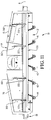
Fig. 12 is an enlarged left top rear perspective view of the cutterhead shown inFig. 11 , showing the positioning of the shield in a generally upright orientation and the brackets for adjustably mounting the shield to the cutterhead shroud, and further showing the port through the shroud; -
Fig. 13 is an enlarged right side elevational view of the cutterhead shown inFig. 11 , showing the positioning of the shield relative to the top front edge of the shroud and the rotating drum; and -
Fig. 14 is an enlarged top left front perspective view of a section of the cutterhead shown inFig. 11 , showing in detail the relative positioning of cutterhead teeth assemblies, and one of the pivot mounts which permit adjustment of the shield relative to the cutterhead shroud. - Referring now to the drawings, a
cutterhead 10 in accordance with the present invention broadly includes a rotatably mounteddrum 12, ashroud 14,drum mounting structure 16 andmotor 18. Thecutterhead 10 is used in conjunction with a dredge 20 which includesengine compartment 22,pontoon hull 24,deck 25,cab 26, and aboom 28 pivotally mounted at the rear of the dredge. As shown in greater detail inFig. 2 , theboom 28 carries apump 30 and pumpmotor 32 for operating the impeller located within thepump 30 and which receives material from theshroud 14 for delivery through theboom 28 to a remote location. Thepump motor 32 and themotor 18 are both preferably hydraulically driven by hydraulic fluid under pressure by power supplied by a hydraulic pump in theengine compartment 22 and delivered through hydraulic conduits 34 (to pump motor), 36 and 38 (to motor 18). - In greater detail, the
drum 12 is substantially cylindrical and presents a smoothouter surface 40 with the exception of anarray 42 of spirally oriented, convergent patterned, radially projectingdrum teeth assemblies 44. Thedrum 12 is preferably made of mild steel which provides sufficient strength and durability, while theteeth assemblies 44 are hardened to cut aquatic vegetation encountered during dredging while at the same time withstanding impacts from rocks or other debris which may have settled into the sediment or other deposit to be dredged. - Turning next to
Figs. 3 and 4 , thedrum 12 includes acenter section 46 and a pair ofend sections end wall 56 at each longitudinal end, and a plurality of circumferentially spaced mountingflanges 58 which project longitudinally at each end and include nuts 60 welded thereto for receiving bolts which project through the surfaces of the end halves 52 and 54 and are threaded into the nuts. This enables easy removal of the end halves 52 and 54 for access to thedrum mounting structure 16. As is easily seen inFigs. 3 and 4 , thearray 42 extends through theend sections array 42 is continuous from the ends of thedrum 12 across theend sections center section 46. - The
array 42 includes two convergent helically orientedflights plates 62 which are welded to thedrum surface 40. The mountingplates 62 are spirally arrayed as shown inFigs. 3 and 4 to provide a toothed cutting surface across virtually the entire width of thedrum 12 whenteeth assemblies 44 are mounted to theplates 62. Each of theteeth assemblies 44 is mounted by two bolts intonuts 61 positioned on the opposite sides of theplates 62, so that every other of theteeth assemblies 44 spans twoplates 62, as best seen inFig. 6 . Each of theteeth assemblies 44 has a cutting margin which may include a leadingcutting edge 64, atip 66, and a trailingcutting edge 68, which features are also seen inFig. 7 , although themotor 18 is preferably a reversible hydraulic motor which permits clearing of theteeth assemblies 44 by backwards rotation when necessary. In normal rotation of the drum12, thearray 42 converges to an apex 69 to effectively auger the cut and dredged material toward the center of thedrum 12. - As best seen in
Figs. 3 ,5 and6 , theshroud 14 includes a pair ofopposed end panels drum mounting structure 16, upper andlower walls walls back wall 80, all preferably of steel plate. Theback wall 80 presents a facing 82 which extends normally above theupper wall 72. Aport 84 is centrally located in the back wall and presents a plurality of surrounding holes to facilitate mounting to thepump 30. -
Stationary cutterbars lower walls Figs. 5 and6 . Eachcutter bar cutterbar teeth assemblies 90 which are configured substantially the same as theteeth assemblies 44 which are parts of thearray 42, and mount toupstanding flanges 92 on eachstationary cutterbar flanges 92 of each cutterbar 86 and 88, and therefore theteeth assemblies 90 carried thereby, is staggered whereby thecutterbar teeth assemblies 90 oncutterbar 86 are not vertically aligned with the correspondingcutterbar teeth assemblies 90 oncutterbar 88. However, the alignment of thecutterbar teeth assemblies 90 corresponds togaps 94 between theteeth assemblies 44 of thearray 42 on thedrum 12, whereby the slight transverse space between theteeth assemblies 44 receives the substantially fore and aft alignedteeth assemblies 90 of the stationary cutterbars 86 and 88, with the distance between thedrum teeth assemblies 44 and thecutterbar teeth assemblies 90 being preferably about ½" at the closest point of approach to yield good cleaning and tearing action during rotation. In order to facilitate access to theteeth assemblies 90 for maintenance by providing adequate spacing therebetween, not everygap 94 receives one of theteeth assemblies 90 therebetween, but in the preferred embodiment shown, approximately two out of every threegaps 94 will receive ateeth assembly 90 therebetween to provide a tearing relationship between theteeth assemblies 90 of thecutterbars teeth assemblies 44 for cutting, writhing and rending any vegetation which wraps around the drum or drapes across theteeth assemblies 44 orteeth assemblies 90. - The
shroud 14 additionally may optionally mountguard teeth assemblies ear plates end panel guard teeth assemblies Fig. 4 ,present cutting edges 104 which are pointed outwardly relative to the axis of rotation A of thedrum 12, and are positioned radially outside thedrum mounting structure 16 but radially interior to theend sections guard teeth assemblies longitudinal margins end panels shroud 14 before such vegetation passes longitudinally toward to the center of thedrum 12 and wraps around thedrum mounting structure 16. - As best seen in
Fig. 5 , thedrum mounting structure 16 is largely conventional and includeshub 110 which permits rotation between theshroud 14 and thedrum 12. Thehub 110 is bolted to theend panel 70 and to theend wall 56 at one end of the center section of thedrum 12. Another hub 112 rigidly connects themotor 18 and thecenter section 46, and is bolted to theend wall 56 and themotor 18. In turn, themotor 18 is rigidly bolted to theend panel 68 and is preferably a reversible hydraulic motor which enables reversing of thedrum 12 to clear any rocks, stumps or other large objects stuck betweenteeth assemblies 44 orteeth assemblies 90. Themotor 18 is driven by hydraulic fluid supplied under pressure and delivered throughconduits Hubs 110 and 112, as well asguard teeth assemblies cavities end walls 56 and radially interior to endsections - The
drum teeth assemblies 44, thecutterhead teeth assemblies 90 and theguard teeth assemblies Figs. 7, 8 ,9 and 10 . Each of theteeth assemblies individual teeth 118 which beneficially are common to each of theteeth assemblies Fig. 8 shows the sameindividual teeth 118 which are used in each of theteeth assemblies plates 62,flanges 92, andear plates individual teeth 118 may be provided with a substantially flatback side 120 and a raised or somewhat convexfront side 122, and have apoint 124 upon which converge twoserrated cutting edges Holes 130 are provided on each of theindividual teeth 118 and aligned in registry when combined in back-to-back relationship in the teeth assemblies to permitbolts 136 to pass therethrough for mounting purposes. Thus, when theindividual teeth 118 are placed back to back and secured together by threaded fasteners such as bolts and nuts or the like, they may compriseteeth assemblies cutting edge 64, atip 66, and a trailingcutting edge 68. As may be seen inFigs. 7 through 10 , and especially in the exploded viewFig. 8 , theindividual teeth 118 of each of the teeth assemblies are plug welded together. Ahole 132 is provided, for example by drilling, at least part way (e.g., approximately 1/4 inch) through approximately the center of one or both of theteeth 118. Theteeth 118 so drilled are placed in back to back relationship with theirholes 130 in registry, and then plug welded such that aplug 134 is positioned and secured in thehole 132, thereby further securedly fixing theteeth 118 in theteeth assemblies individual teeth 118 with the raised or convex surface exteriors facing outwardly and the flat back surfaces 120 together, theteeth assemblies individual teeth 118 of the teeth assemblies provides exceptional and surprising strength, providing lamination in the teeth assemblies so that the teeth assemblies last longer and avoid bending. Thus, such plug weldedteeth assemblies - Turning now to
Figs. 11-14 , thecutterhead 10 may be provided with ashield 136 which is preferably adjustably mounted to theshroud 14 along or adjacent a topfront edge 138 of theshroud 14. Theshield 136 may preferably extend the width of theshroud 14, and may have a height which may be greater than the radius of thecylindrical drum 12 and most preferably greater than the radial distance from the axis of rotation of thedrum 12 to thepoint 124 of theteeth 118 on thedrum 12. The teeth may be either back to backteeth 118 as shown and described with reference toFigs. 6-10 asteeth assemblies individual teeth 118A as shown inFig. 14 , having serrated leading and trailing cutting edges. - The
shield 136 may be fabricated of metal, such as aluminum or steel, and preferably presents a relatively flat, planarfront panel 140 which thus resists collection of liquid and cut vegetation thereon, but rather deflects any such liquid or vegetation contacting thefront panel 140. Theshield 136 preferably includes aproximate margin 142, aremote margin 144, and left andright side margins front panel 140 to provide rigidity and reinforcement. Theremote margin 144 andside margins front panel 140 and be angled approximately 90 from the front panel to enhance strength and rigidity, while theproximate margin 142 may be angled approximately 45° from the front panel to both enhance the strength and the range of pivotal adjustment of theshield 136 relative to theshroud 14. An innerproximate wall 150 oriented substantially perpendicular to thefront panel 140 encloses the space within theproximate margin 142 to resist collection of cut vegetation and water therein. A plurality oftabs 152 extend from theproximate margin 142 and are laterally spaced along the width of theshield 136. Thetabs 152 are positioned adjacent laterally spaced reinforcingbars 155 which preferably extend between theremote margin 144 and the innerproximate wall 150. Thetabs 152 may have holes into whichcouplers 154 such as pivot pins, bolts or other threaded fasteners are received to pivotally mount theshield 136 to theshroud 14. - In order to most advantageously mount the
shield 136, a mountingbar 156 may extend along the topfront edge 138 of theshroud 14. The mountingbar 156 may carry a plurality of generally forwardly and/or upwardly extending mountingflanges 158 which have holes complementally sized and positioned relative to the holes in thetabs 152 for receiving thecouplers 154 therethrough. Thus, the shield may swing about thecouplers 154 for positioning on one of a plurality of preselected desired orientations. - A plane P extends forwardly from the
upper wall 72 of theshroud 14, which inFig. 13 is generally flat, and thus the plane lies along the flat upper surface of theupper wall 72.Brackets 160 may be laterally spaced along theupper wall 72 of theshroud 14. Thebrackets 160 are generally oriented fore-and-aft alongupper wall 72, and are preferably positioned in planes generally perpendicular to both plane P and the axis A of rotation of thedrum 12. Each of thebrackets 160 may include a series of fore-and-aft spacedholes 162, foursuch holes 162 being illustrated on each of thebrackets 160 in the drawing ofFigs. 12 and 13 . Theholes 162 are positioned and configured to mount aproximate end 164 ofstruts 166 by the use ofcouplers 154, such that each of the holes 162 (i.e., 162A, 162B, 162C and 162D) on abracket 160 provides an alternate mounting location. Thestruts 166 are also provided with aremote end 168, which is pivotally mounted bycouplers 154 to a hole in a respective one of the reinforcing bars 155. By removing thecouplers 154 from the proximate ends 164 of thestruts 166 and repositioning the holes throughproximate ends 164 of thestruts 166 in alignment with a different one of theholes 162 of abracket 160 and then reattaching thecouplers 154, the angle of thefront panel 140 relative to the plane P along the surface of theupper wall 72 may be adjusted. For example,Fig. 13 shows the proximate ends 164 ofstruts 166 attached in therearmost hole 162D of thebracket 160, whereby thefront panel 140 of theshield 136 is oriented at about 70° from the plane P. However, by removing thecouplers 154, pivoting the shield forwardly (clockwise as depicted inFig. 13 ) about a pivot axis defined by the holes in thetabs 152 and thecouplers 154 passing therethrough, the angle may be adjusted and maintained by reattaching the proximate ends 164 of thestruts 166 to thebrackets 160 by securing thecouplers 154 through eitherhole frontmost hole 162A is used, the angle may be reduced to about 10°. By lengthening thebrackets 160 or providingadditional holes 162, additional preselected angles for pivoting theshield 136 may be provided. - In preparation for use of the
cutterhead 10, theshroud 14 is bolted to thepump 30, theconduits boom 28 is lowered by the operator in the cab to begin dredging. Any aquatic vegetation encountered during dredging is severed and cut by the cutting action of theteeth assemblies 44 while thedrum 12 rotates, and further enhanced by the tearing action between thecutterhead teeth assemblies 90 mounted on the stationary cutterbars whenteeth 44 pass thereby. In addition, whenguard teeth assemblies longitudinal margins end panels shroud 14, preventing such vegetation from passing longitudinally toward the center of thedrum 12 and wrapping around thedrum mounting structure 16. Theteeth assemblies 44 present a cutting surface which may extend transversely across substantially the entire length of thedrum 12, and thus any vegetation passing across the path of thedrum 12 will be engaged by one or more of theteeth assemblies 44. As noted, except for theteeth assemblies 44, thedrum 12 presents a substantially smooth surface which inhibits the ability of any vegetation to cling to the drum and become draped across it, thereby accumulating and fouling thecutterhead 10. - The
array 42 ofteeth assemblies 44 acts further as an auger to move any dredged sediment and cut vegetation to the center of thedrum 12 and thus immediately proximate theport 84 for passage into thepump 30. Thecutterhead 10 chops the vegetation into small enough pieces to avoid jamming thepump 30, and thus the cut vegetation and the sediment or other deposits can be effectively dredged. Many types of aquatic vegetation including floating plants like hyacinth, submerged vegetation such as milfoil and hydrilla, and emergent vegetation such as cattail and small willows can be cut and removed using thecutterhead 10 hereof, as well as aquatic plants sometimes called tussiks. As in conventional dredging practice, theboom 28 is raised or lowered by a winch mounted on the dredge 20 to engage the vegetation and sediment or other deposits to the desired depth, and the dredge 20 may be self-powered or positioned by shore-anchored cables to direct thecutterhead 10 laterally into position. The angle of theshield 136 relative to the plane P of thetop wall 72 of thecutterhead shroud 14 may be adjusted as desired according to whether the cutterhead is to be operated at a depth or along the surface of the body of water in which the vegetation to be harvested is located. Theshield 136 may also be adjusted as desired with respect to its relative orientation to thetop wall 72 based on the type of vegetation being cut and how the vegetation may thus most effectively be fed into theshroud 14. - Although preferred forms of the invention have been described above, it is to be recognized that such disclosure is by way of illustration only. Obvious modifications to the exemplary embodiments, as hereinabove set forth, could be readily made by those skilled in the art in the limit of the claims.
Claims (16)
- Apparatus for cutting aquatic vegetation comprising:a first stationary cutterbar (86) presenting a first set of spaced-apart cutterbar teeth assemblies (90) mounted therealong;a second stationary cutterbar (88) presenting a second set of spaced-apart cutterbar teeth assemblies (90) mounted therealong;a cutterhead shroud (14) mounting said first and second stationary cutterbar;a drum rotatably mounted proximate said cutterhead shroud, said drum presenting a substantially smooth drum surface and presenting a plurality of radially projecting drum teeth assemblies therealong; andmeans mounting said drum teeth assemblies (44) to present gaps (94) between the points thereof whereby some of said drum teeth assemblies (44) pass closely adjacent said first set of cutterbar teeth assemblies (86,90) in tearing relationship thereto and others of said drum teeth assemblies (44) pass closely adjacent said second set of cutterbar teeth assemblies (88,90), in tearing relationship thereto, during rotation of said drum (12),characterized in that the drum teeth assemblies (44) include a first tooth and a second tooth (118), each of the teeth (118) having a flat back (120), a raised front and a cutting margin (126,128), the first and second teeth (118) being mounted in back- to-back arrangement whereby their cutting margins (126,128) are adjacent and the backs (120) are substantially co-planar.
- An apparatus for cutting aquatic vegetation as set forth in claim 1, characterized in that it further comprises:a cutterhead shroud (14) presenting an port (84) for passing cut vegetation therethrough, said shroud presenting advantageously two opposed end panels, said port being located substantially equidistant between said end panels;means mounting said drum for rotation relative to said shroud; anda motor (18) for rotating said drum (12); andan array of drum teeth assemblies (44) projecting radially from said drum (12), said array being of a substantially helical configuration about said drum (12) for promoting movement of the cut vegetation to said port during rotation of said drum, said array comprising advantageously two substantially helical and convergent flights of drum teeth assemblies.
- An apparatus as set forth in claim 1 wherein said drum teeth assemblies (44) are presented in a helically oriented array across at least a part of said drum (12).
- An apparatus as set forth in claim 1 or 2, wherein said drum teeth assemblies (44) are positioned in an array (42) extending substantially the longitudinal length of said drum (12) to present a substantially continuous cutting edge (64) extending along the longitudinal length of said drum (12), each of said drum teeth assemblies (44) being advantageously positioned in overlapping relationship to the drum teeth assembly (44) next adjacent thereto.
- An apparatus as set forth in claim 1 or 2, wherein said drum teeth assemblies (44) are coupled to said drum (12) by threaded fasteners (61).
- An apparatus as set forth in claim 1 or 2, wherein the first and second teeth (118) of at least one drum tooth assembly (44) are connected by a weld, advantageously a plug weld.
- An apparatus as set forth in claim 1, wherein said drum (12) is substantially cylindrical and presents longitudinally spaced ends having open-ended cavities (114,116) radially interior to said drum surface (40) at each end of said drum (12), whereby at least one radially outwardly projecting teeth assembly (96,98) is positioned in each of said cavities (114,116) for cutting vegetation passing between said shroud (14) and said drum ends (106,108).
- An apparatus as set forth in claim 1 or 2, wherein the cutting margin of the first and second teeth (118) of at least one drum tooth assembly (90) is serrated.
- An apparatus as set forth in claim 1 or 2, wherein the teeth assemblies (118) of said first set of spaced-apart cutterbar teeth assemblies (90) include a first tooth and a second tooth, each of the teeth (118) having a flat back (120), a raised front and a cutting margin (126,128), the first and second teeth being mounted in back-to-back arrangement whereby their cutting margins (126,128) are adjacent and the backs are substantially co-planar, wherein the cutting margin (126,128) of the first and second teeth of at least one of the teeth assemblies (118) of the first set of cutterbar teeth assemblies (86) is advantageously serrated, while the teeth assemblies (118) of said second set of spaced-apart cutterbar teeth assemblies include preferably a first tooth and a second tooth, each of the teeth having a flat back (120), a raised front and a cutting margin, the first and second teeth being mounted in back- to-back arrangement whereby their cutting margins are adjacent and the backs are substantially co-planar, said cutting margin (126,128) of the first and second teeth of at least one of the teeth assemblies of the second set of cutterbar teeth assemblies being most preferably serrated.
- An apparatus as set forth in claim 1 or 2, further including a shield mounted to said cutterhead shroud (14) and extending forwardly and/or upwardly from a top front edge of said cutterhead shroud, wherein said shield is advantageously mounted adjacent said top front edge of said cutterhead shroud (14).
- An apparatus as set forth in claim 10, including a mounting assembly adjustably mounting said shield to said cutterhead shroud, wherein said mounting assembly includes advantageously a plurality of brackets on a top wall of said cutterhead shroud and a plurality of struts mounted to respective ones of said brackets and to said shield, each of said brackets including preferably a plurality of spaced apart holes configured and positioned for alternatively receiving a coupler connecting a respective strut to said bracket.
- An apparatus as set forth in claim 2, including threaded fasteners for removably attaching said drum teeth assemblies to said drum.
- An apparatus as set forth in any one of the preceding claims, further comprising a pump for receiving cu vegetation from the shroud 14 and means for conveying cut vegetation from said pump.
- A method of cutting aquatic vegetation by means of an apparatus according to any one of the preceding claims.
- A method of cutting aquatic vegetation of claim 14 comprising the steps of:providing a dredge including a pump and means for conveying cut vegetation from said pump, said pump mounting a cutterhead having a shroud and a drum, said drum presenting a substantially helical array of drum teeth assemblies, said teeth assemblies including a first tooth and a second tooth, each of the teeth having a flat back, a raised front and a cutting margin, the first and second teeth being mounted in back-to-back arrangement whereby their cutting margins are adjacent and the backs are substantially co-planar, said shroud presenting at least one stationary cutterbar presenting a plurality of cutterbar teeth assemblies, at least some of said cutterbar teeth assemblies being oriented in vegetation tearing relationship to said drum when said drum is rotated relative to said shroud, said shroud further including a port for passing cut vegetation to said pump;placing said cutterhead in engagement with aquatic vegetation;rotating said drum to cut said vegetation;moving said vegetation transversely along said drum by augering action of said helical array of teeth; and passing said vegetation through said port and into said pump.
- A method of cutting aquatic vegetation of claim 14 comprising the steps of:providing a dredge including a pump and means for conveying cut vegetation from said pump, said pump mounting a cutterhead having a shroud and a drum, said drum presenting a substantially helical array of drum teeth assemblies, said shroud presenting at least one stationary cutterbar presenting a plurality of cutterbar teeth assemblies, at least some of said cutterbar teeth assemblies being oriented in vegetation tearing relationship to said drum when said drum is rotated relative to said shroud, said shroud further including a port for passing cut vegetation to said pump and a shield extending upwardly and/or forwardly of a top front edge of said shroud; placing said cutterhead in engagement with aquatic vegetation;rotating said drum to cut said vegetation;moving said vegetation transversely along said drum by augering action of said helical array of teeth;deflecting water and/or vegetation contacting said shield towards said rotating drum; andpassing said vegetation through said port and into said pump.
Applications Claiming Priority (5)
| Application Number | Priority Date | Filing Date | Title |
|---|---|---|---|
| US201261698476P | 2012-09-07 | 2012-09-07 | |
| US201261735905P | 2012-12-11 | 2012-12-11 | |
| US201361803744P | 2013-03-20 | 2013-03-20 | |
| US14/014,246 US9060464B2 (en) | 2012-09-07 | 2013-08-29 | Method and apparatus for dredging and removing aquatic vegetation |
| PCT/US2013/058795 WO2014039989A1 (en) | 2012-09-07 | 2013-09-09 | Method and apparatus for dredging and removing aquatic vegetation |
Publications (3)
| Publication Number | Publication Date |
|---|---|
| EP2892316A1 EP2892316A1 (en) | 2015-07-15 |
| EP2892316A4 EP2892316A4 (en) | 2016-05-11 |
| EP2892316B1 true EP2892316B1 (en) | 2017-12-20 |
Family
ID=50231805
Family Applications (1)
| Application Number | Title | Priority Date | Filing Date |
|---|---|---|---|
| EP13835278.6A Active EP2892316B1 (en) | 2012-09-07 | 2013-09-09 | Method and apparatus for dredging and removing aquatic vegetation |
Country Status (4)
| Country | Link |
|---|---|
| US (1) | US9060464B2 (en) |
| EP (1) | EP2892316B1 (en) |
| TR (1) | TR201802231T4 (en) |
| WO (1) | WO2014039989A1 (en) |
Families Citing this family (5)
| Publication number | Priority date | Publication date | Assignee | Title |
|---|---|---|---|---|
| US9493215B2 (en) * | 2013-06-12 | 2016-11-15 | Liquid Waste Technology, Llc | Floating debris harvesting system |
| WO2016012529A1 (en) * | 2014-07-23 | 2016-01-28 | Géco Ingénierie | Device and method for dredging a watercourse or body of water, bag for plant matter, and method for storing plant matter |
| US10602663B2 (en) | 2016-09-19 | 2020-03-31 | Nicholas James Szabo | Aquatic vegetation harvesting system |
| CN107969208B (en) * | 2017-11-21 | 2019-07-05 | 中国科学院海洋研究所 | Knife and method for mechanized harvesting of kelp |
| CN107878692B (en) * | 2017-11-22 | 2023-11-10 | 济南大学 | Lake river grass plant cleaning device |
Family Cites Families (27)
| Publication number | Priority date | Publication date | Assignee | Title |
|---|---|---|---|---|
| US669820A (en) | 1898-04-30 | 1901-03-12 | Francis Martin | Channel-clearer. |
| US1028671A (en) | 1912-03-11 | 1912-06-04 | Reuben Brooks | Marine harvester. |
| US1795003A (en) | 1928-10-04 | 1931-03-03 | Edward B Allen | Means for destroying marine growths impeding navigation |
| US2223641A (en) | 1939-01-20 | 1940-12-03 | George P Sanger | Weeding apparatus |
| US2486275A (en) | 1948-06-26 | 1949-10-25 | Mathias E Grinwald | Machine for harvesting and baling underwater plant life |
| US2635406A (en) | 1950-03-14 | 1953-04-21 | Willie L Chauvin | Vehicle for cutting marine growth |
| US2702975A (en) | 1952-05-24 | 1955-03-01 | Albert W Friesen | Underwater weed cutter |
| US3238708A (en) | 1964-08-10 | 1966-03-08 | Franklin L Zickefoose | Aquatic weed cutter |
| US3407577A (en) | 1965-12-20 | 1968-10-29 | Jari Corp | Underwater weed cutter drive mechanism |
| US3468106A (en) | 1966-09-08 | 1969-09-23 | Robert R Myers | Aquatic weed harvester |
| US3653192A (en) | 1970-12-14 | 1972-04-04 | Bryant Charles B | Method and apparatus for harvesting aquatic vegetation |
| US4070978A (en) | 1976-07-01 | 1978-01-31 | Virgilio Del P | Floating apparatus for weeding and dredging waterways |
| US4095545A (en) | 1977-03-02 | 1978-06-20 | Vmi, Inc. | Self-propelled dredging apparatus |
| US4196566A (en) | 1978-04-07 | 1980-04-08 | Donnelley Elliott R | Aquatic weed cutter |
| US4205507A (en) | 1978-08-02 | 1980-06-03 | Mcclure James R | Aquatic weed cutting apparatus |
| US4248033A (en) | 1979-03-07 | 1981-02-03 | Bryant Charles B | Thru-flow aquatic harvester |
| US4416106A (en) | 1982-04-08 | 1983-11-22 | Hawk James L | Method and apparatus for removal of aquatic plant growth |
| SU1102514A1 (en) * | 1983-03-30 | 1984-07-15 | Калининский Ордена Трудового Красного Знамени Политехнический Институт | Machine for mowing and and harvesting water plants |
| JPS6189198A (en) * | 1984-10-05 | 1986-05-07 | Mitsui Eng & Shipbuild Co Ltd | Water grass treating ship |
| US4616588A (en) | 1985-01-09 | 1986-10-14 | Caddick Mary J | Water craft and method for removing weeds and pollutants from navigable waters |
| US4815260A (en) | 1986-12-05 | 1989-03-28 | Desrosiers J Armand | Plant harvester |
| SU1658875A1 (en) * | 1989-05-04 | 1991-06-30 | Г.Т.Шпаков, В.Г.Шпаков и Е.Г.Шпаков | Device for extracting algae |
| US5481856A (en) | 1994-11-18 | 1996-01-09 | Innovative Material Systems, Inc. | Method and apparatus for cutting aquatic vegetation |
| US6511374B2 (en) * | 2001-02-02 | 2003-01-28 | Case Corporation | Hub and blade assembly for an agricultural combine residue handling system |
| AU2003250616B1 (en) * | 2002-08-26 | 2004-02-19 | Freshwater Environmental Management Pty Ltd | Harvester |
| DE502004001239D1 (en) * | 2003-05-17 | 2006-10-05 | Deere & Co | Chopping knife for a straw chopper |
| US8333056B2 (en) * | 2010-10-29 | 2012-12-18 | Liquid Waste Technology, Llc | Non-binding cutterhead for cutting aquatic vegetation |
-
2013
- 2013-08-29 US US14/014,246 patent/US9060464B2/en active Active
- 2013-09-09 EP EP13835278.6A patent/EP2892316B1/en active Active
- 2013-09-09 TR TR2018/02231T patent/TR201802231T4/en unknown
- 2013-09-09 WO PCT/US2013/058795 patent/WO2014039989A1/en not_active Ceased
Non-Patent Citations (1)
| Title |
|---|
| None * |
Also Published As
| Publication number | Publication date |
|---|---|
| US20140069071A1 (en) | 2014-03-13 |
| EP2892316A1 (en) | 2015-07-15 |
| WO2014039989A1 (en) | 2014-03-13 |
| EP2892316A4 (en) | 2016-05-11 |
| TR201802231T4 (en) | 2018-03-21 |
| US9060464B2 (en) | 2015-06-23 |
Similar Documents
| Publication | Publication Date | Title |
|---|---|---|
| US5481856A (en) | Method and apparatus for cutting aquatic vegetation | |
| US9060464B2 (en) | Method and apparatus for dredging and removing aquatic vegetation | |
| US10000905B2 (en) | Cutterhead debris guard | |
| US3866396A (en) | Removal of marine growths from lakes, waterways, and other bodies of water | |
| DE2513675C3 (en) | Cutter suction dredger | |
| US20140367342A1 (en) | Floating debris harvesting system | |
| US8333056B2 (en) | Non-binding cutterhead for cutting aquatic vegetation | |
| US9374938B2 (en) | Soil spreading scraper device | |
| US5542240A (en) | Water craft for reducing aquatic plant infestation | |
| CN102972147A (en) | Full-automatic underwater weeding ship | |
| EP3860773B1 (en) | Net cleaning device for in-situ cleaning of a submerged net, propeller for use with net cleaning device, method and system | |
| US5027534A (en) | Power ditch router | |
| US5617654A (en) | Dredge rotary cutter head | |
| US5447018A (en) | Aquatic plant de-rooting apparatus | |
| EP2743406B1 (en) | Device for excavating a channel | |
| US10544563B1 (en) | Spring loaded feeding device | |
| EP0236692B1 (en) | Cutting wheel device | |
| DE3426328C2 (en) | Cutting head impeller | |
| US10550544B1 (en) | Spring loaded feeding device | |
| CN114293612B (en) | Underwater silt removing device | |
| EP0226660A1 (en) | Digging bucket wheel device | |
| CN220606580U (en) | Drag type grass cleaning device | |
| US2949945A (en) | Cutter type land clearing implement | |
| US4517754A (en) | Cutterhead attachment for a dredge | |
| HK40058528B (en) | Net cleaning device for in-situ cleaning of a submerged net, propeller for use with net cleaning device, method and system |
Legal Events
| Date | Code | Title | Description |
|---|---|---|---|
| PUAI | Public reference made under article 153(3) epc to a published international application that has entered the european phase |
Free format text: ORIGINAL CODE: 0009012 |
|
| 17P | Request for examination filed |
Effective date: 20150305 |
|
| AK | Designated contracting states |
Kind code of ref document: A1 Designated state(s): AL AT BE BG CH CY CZ DE DK EE ES FI FR GB GR HR HU IE IS IT LI LT LU LV MC MK MT NL NO PL PT RO RS SE SI SK SM TR |
|
| AX | Request for extension of the european patent |
Extension state: BA ME |
|
| RIN1 | Information on inventor provided before grant (corrected) |
Inventor name: YOUNG, MICHAEL, TODD Inventor name: HORTON, RYAN PATRICK |
|
| DAX | Request for extension of the european patent (deleted) | ||
| RA4 | Supplementary search report drawn up and despatched (corrected) |
Effective date: 20160411 |
|
| RIC1 | Information provided on ipc code assigned before grant |
Ipc: A01D 44/00 20060101AFI20160405BHEP |
|
| GRAP | Despatch of communication of intention to grant a patent |
Free format text: ORIGINAL CODE: EPIDOSNIGR1 |
|
| INTG | Intention to grant announced |
Effective date: 20170821 |
|
| GRAS | Grant fee paid |
Free format text: ORIGINAL CODE: EPIDOSNIGR3 |
|
| GRAA | (expected) grant |
Free format text: ORIGINAL CODE: 0009210 |
|
| AK | Designated contracting states |
Kind code of ref document: B1 Designated state(s): AL AT BE BG CH CY CZ DE DK EE ES FI FR GB GR HR HU IE IS IT LI LT LU LV MC MK MT NL NO PL PT RO RS SE SI SK SM TR |
|
| REG | Reference to a national code |
Ref country code: GB Ref legal event code: FG4D |
|
| REG | Reference to a national code |
Ref country code: CH Ref legal event code: EP |
|
| REG | Reference to a national code |
Ref country code: IE Ref legal event code: FG4D |
|
| REG | Reference to a national code |
Ref country code: AT Ref legal event code: REF Ref document number: 955495 Country of ref document: AT Kind code of ref document: T Effective date: 20180115 |
|
| REG | Reference to a national code |
Ref country code: DE Ref legal event code: R096 Ref document number: 602013031193 Country of ref document: DE |
|
| REG | Reference to a national code |
Ref country code: NL Ref legal event code: FP |
|
| PG25 | Lapsed in a contracting state [announced via postgrant information from national office to epo] |
Ref country code: LT Free format text: LAPSE BECAUSE OF FAILURE TO SUBMIT A TRANSLATION OF THE DESCRIPTION OR TO PAY THE FEE WITHIN THE PRESCRIBED TIME-LIMIT Effective date: 20171220 Ref country code: NO Free format text: LAPSE BECAUSE OF FAILURE TO SUBMIT A TRANSLATION OF THE DESCRIPTION OR TO PAY THE FEE WITHIN THE PRESCRIBED TIME-LIMIT Effective date: 20180320 Ref country code: SE Free format text: LAPSE BECAUSE OF FAILURE TO SUBMIT A TRANSLATION OF THE DESCRIPTION OR TO PAY THE FEE WITHIN THE PRESCRIBED TIME-LIMIT Effective date: 20171220 |
|
| REG | Reference to a national code |
Ref country code: LT Ref legal event code: MG4D |
|
| REG | Reference to a national code |
Ref country code: AT Ref legal event code: MK05 Ref document number: 955495 Country of ref document: AT Kind code of ref document: T Effective date: 20171220 |
|
| PG25 | Lapsed in a contracting state [announced via postgrant information from national office to epo] |
Ref country code: LV Free format text: LAPSE BECAUSE OF FAILURE TO SUBMIT A TRANSLATION OF THE DESCRIPTION OR TO PAY THE FEE WITHIN THE PRESCRIBED TIME-LIMIT Effective date: 20171220 Ref country code: HR Free format text: LAPSE BECAUSE OF FAILURE TO SUBMIT A TRANSLATION OF THE DESCRIPTION OR TO PAY THE FEE WITHIN THE PRESCRIBED TIME-LIMIT Effective date: 20171220 Ref country code: BG Free format text: LAPSE BECAUSE OF FAILURE TO SUBMIT A TRANSLATION OF THE DESCRIPTION OR TO PAY THE FEE WITHIN THE PRESCRIBED TIME-LIMIT Effective date: 20180320 Ref country code: RS Free format text: LAPSE BECAUSE OF FAILURE TO SUBMIT A TRANSLATION OF THE DESCRIPTION OR TO PAY THE FEE WITHIN THE PRESCRIBED TIME-LIMIT Effective date: 20171220 Ref country code: GR Free format text: LAPSE BECAUSE OF FAILURE TO SUBMIT A TRANSLATION OF THE DESCRIPTION OR TO PAY THE FEE WITHIN THE PRESCRIBED TIME-LIMIT Effective date: 20180321 |
|
| PG25 | Lapsed in a contracting state [announced via postgrant information from national office to epo] |
Ref country code: CZ Free format text: LAPSE BECAUSE OF FAILURE TO SUBMIT A TRANSLATION OF THE DESCRIPTION OR TO PAY THE FEE WITHIN THE PRESCRIBED TIME-LIMIT Effective date: 20171220 Ref country code: ES Free format text: LAPSE BECAUSE OF FAILURE TO SUBMIT A TRANSLATION OF THE DESCRIPTION OR TO PAY THE FEE WITHIN THE PRESCRIBED TIME-LIMIT Effective date: 20171220 Ref country code: EE Free format text: LAPSE BECAUSE OF FAILURE TO SUBMIT A TRANSLATION OF THE DESCRIPTION OR TO PAY THE FEE WITHIN THE PRESCRIBED TIME-LIMIT Effective date: 20171220 Ref country code: CY Free format text: LAPSE BECAUSE OF FAILURE TO SUBMIT A TRANSLATION OF THE DESCRIPTION OR TO PAY THE FEE WITHIN THE PRESCRIBED TIME-LIMIT Effective date: 20171220 Ref country code: SK Free format text: LAPSE BECAUSE OF FAILURE TO SUBMIT A TRANSLATION OF THE DESCRIPTION OR TO PAY THE FEE WITHIN THE PRESCRIBED TIME-LIMIT Effective date: 20171220 |
|
| PG25 | Lapsed in a contracting state [announced via postgrant information from national office to epo] |
Ref country code: RO Free format text: LAPSE BECAUSE OF FAILURE TO SUBMIT A TRANSLATION OF THE DESCRIPTION OR TO PAY THE FEE WITHIN THE PRESCRIBED TIME-LIMIT Effective date: 20171220 Ref country code: IS Free format text: LAPSE BECAUSE OF FAILURE TO SUBMIT A TRANSLATION OF THE DESCRIPTION OR TO PAY THE FEE WITHIN THE PRESCRIBED TIME-LIMIT Effective date: 20180420 Ref country code: PL Free format text: LAPSE BECAUSE OF FAILURE TO SUBMIT A TRANSLATION OF THE DESCRIPTION OR TO PAY THE FEE WITHIN THE PRESCRIBED TIME-LIMIT Effective date: 20171220 Ref country code: SM Free format text: LAPSE BECAUSE OF FAILURE TO SUBMIT A TRANSLATION OF THE DESCRIPTION OR TO PAY THE FEE WITHIN THE PRESCRIBED TIME-LIMIT Effective date: 20171220 Ref country code: AT Free format text: LAPSE BECAUSE OF FAILURE TO SUBMIT A TRANSLATION OF THE DESCRIPTION OR TO PAY THE FEE WITHIN THE PRESCRIBED TIME-LIMIT Effective date: 20171220 |
|
| REG | Reference to a national code |
Ref country code: DE Ref legal event code: R097 Ref document number: 602013031193 Country of ref document: DE |
|
| PLBE | No opposition filed within time limit |
Free format text: ORIGINAL CODE: 0009261 |
|
| STAA | Information on the status of an ep patent application or granted ep patent |
Free format text: STATUS: NO OPPOSITION FILED WITHIN TIME LIMIT |
|
| 26N | No opposition filed |
Effective date: 20180921 |
|
| PG25 | Lapsed in a contracting state [announced via postgrant information from national office to epo] |
Ref country code: DK Free format text: LAPSE BECAUSE OF FAILURE TO SUBMIT A TRANSLATION OF THE DESCRIPTION OR TO PAY THE FEE WITHIN THE PRESCRIBED TIME-LIMIT Effective date: 20171220 |
|
| PG25 | Lapsed in a contracting state [announced via postgrant information from national office to epo] |
Ref country code: SI Free format text: LAPSE BECAUSE OF FAILURE TO SUBMIT A TRANSLATION OF THE DESCRIPTION OR TO PAY THE FEE WITHIN THE PRESCRIBED TIME-LIMIT Effective date: 20171220 |
|
| PG25 | Lapsed in a contracting state [announced via postgrant information from national office to epo] |
Ref country code: MC Free format text: LAPSE BECAUSE OF FAILURE TO SUBMIT A TRANSLATION OF THE DESCRIPTION OR TO PAY THE FEE WITHIN THE PRESCRIBED TIME-LIMIT Effective date: 20171220 |
|
| REG | Reference to a national code |
Ref country code: CH Ref legal event code: PL |
|
| GBPC | Gb: european patent ceased through non-payment of renewal fee |
Effective date: 20180909 |
|
| REG | Reference to a national code |
Ref country code: BE Ref legal event code: MM Effective date: 20180930 |
|
| REG | Reference to a national code |
Ref country code: IE Ref legal event code: MM4A |
|
| PG25 | Lapsed in a contracting state [announced via postgrant information from national office to epo] |
Ref country code: LU Free format text: LAPSE BECAUSE OF NON-PAYMENT OF DUE FEES Effective date: 20180909 |
|
| PG25 | Lapsed in a contracting state [announced via postgrant information from national office to epo] |
Ref country code: IE Free format text: LAPSE BECAUSE OF NON-PAYMENT OF DUE FEES Effective date: 20180909 |
|
| PG25 | Lapsed in a contracting state [announced via postgrant information from national office to epo] |
Ref country code: FR Free format text: LAPSE BECAUSE OF NON-PAYMENT OF DUE FEES Effective date: 20180930 Ref country code: BE Free format text: LAPSE BECAUSE OF NON-PAYMENT OF DUE FEES Effective date: 20180930 Ref country code: LI Free format text: LAPSE BECAUSE OF NON-PAYMENT OF DUE FEES Effective date: 20180930 Ref country code: CH Free format text: LAPSE BECAUSE OF NON-PAYMENT OF DUE FEES Effective date: 20180930 |
|
| PG25 | Lapsed in a contracting state [announced via postgrant information from national office to epo] |
Ref country code: GB Free format text: LAPSE BECAUSE OF NON-PAYMENT OF DUE FEES Effective date: 20180909 |
|
| PG25 | Lapsed in a contracting state [announced via postgrant information from national office to epo] |
Ref country code: MT Free format text: LAPSE BECAUSE OF NON-PAYMENT OF DUE FEES Effective date: 20180909 |
|
| PG25 | Lapsed in a contracting state [announced via postgrant information from national office to epo] |
Ref country code: PT Free format text: LAPSE BECAUSE OF FAILURE TO SUBMIT A TRANSLATION OF THE DESCRIPTION OR TO PAY THE FEE WITHIN THE PRESCRIBED TIME-LIMIT Effective date: 20171220 |
|
| PG25 | Lapsed in a contracting state [announced via postgrant information from national office to epo] |
Ref country code: HU Free format text: LAPSE BECAUSE OF FAILURE TO SUBMIT A TRANSLATION OF THE DESCRIPTION OR TO PAY THE FEE WITHIN THE PRESCRIBED TIME-LIMIT; INVALID AB INITIO Effective date: 20130909 Ref country code: MK Free format text: LAPSE BECAUSE OF NON-PAYMENT OF DUE FEES Effective date: 20171220 |
|
| PG25 | Lapsed in a contracting state [announced via postgrant information from national office to epo] |
Ref country code: AL Free format text: LAPSE BECAUSE OF FAILURE TO SUBMIT A TRANSLATION OF THE DESCRIPTION OR TO PAY THE FEE WITHIN THE PRESCRIBED TIME-LIMIT Effective date: 20171220 |
|
| REG | Reference to a national code |
Ref country code: DE Ref legal event code: R081 Ref document number: 602013031193 Country of ref document: DE Owner name: ELLICOTT DREDGE TECHNOLOGIES, LLC, NEW RICHMON, US Free format text: FORMER OWNER: LIQUID WASTE TECHNOLOGY, LLC, NEW RICHMOND, WIS., US |
|
| REG | Reference to a national code |
Ref country code: NL Ref legal event code: HC Owner name: ELLICOTT DREDGE TECHNOLOGIES, LLC.; US Free format text: DETAILS ASSIGNMENT: CHANGE OF OWNER(S), CHANGE OF OWNER(S) NAME; FORMER OWNER NAME: LIQUID WASTE TECHNOLOGY, LLC Effective date: 20230828 |
|
| P01 | Opt-out of the competence of the unified patent court (upc) registered |
Effective date: 20231027 |
|
| PGFP | Annual fee paid to national office [announced via postgrant information from national office to epo] |
Ref country code: FI Payment date: 20250925 Year of fee payment: 13 |
|
| PGFP | Annual fee paid to national office [announced via postgrant information from national office to epo] |
Ref country code: DE Payment date: 20250929 Year of fee payment: 13 |
|
| PGFP | Annual fee paid to national office [announced via postgrant information from national office to epo] |
Ref country code: TR Payment date: 20250822 Year of fee payment: 13 Ref country code: IT Payment date: 20250919 Year of fee payment: 13 Ref country code: NL Payment date: 20250926 Year of fee payment: 13 |