EP2892193B1 - I/Q-mismatch compensation method and apparatus - Google Patents
I/Q-mismatch compensation method and apparatus Download PDFInfo
- Publication number
- EP2892193B1 EP2892193B1 EP14200633.7A EP14200633A EP2892193B1 EP 2892193 B1 EP2892193 B1 EP 2892193B1 EP 14200633 A EP14200633 A EP 14200633A EP 2892193 B1 EP2892193 B1 EP 2892193B1
- Authority
- EP
- European Patent Office
- Prior art keywords
- receiver
- transmitter
- mismatch
- training sequence
- loopback path
- Prior art date
- Legal status (The legal status is an assumption and is not a legal conclusion. Google has not performed a legal analysis and makes no representation as to the accuracy of the status listed.)
- Active
Links
Images




Classifications
-
- H—ELECTRICITY
- H04—ELECTRIC COMMUNICATION TECHNIQUE
- H04B—TRANSMISSION
- H04B17/00—Monitoring; Testing
- H04B17/10—Monitoring; Testing of transmitters
- H04B17/11—Monitoring; Testing of transmitters for calibration
- H04B17/14—Monitoring; Testing of transmitters for calibration of the whole transmission and reception path, e.g. self-test loop-back
-
- H—ELECTRICITY
- H03—ELECTRONIC CIRCUITRY
- H03D—DEMODULATION OR TRANSFERENCE OF MODULATION FROM ONE CARRIER TO ANOTHER
- H03D3/00—Demodulation of angle-, frequency- or phase- modulated oscillations
- H03D3/007—Demodulation of angle-, frequency- or phase- modulated oscillations by converting the oscillations into two quadrature related signals
- H03D3/009—Compensating quadrature phase or amplitude imbalances
-
- H—ELECTRICITY
- H04—ELECTRIC COMMUNICATION TECHNIQUE
- H04B—TRANSMISSION
- H04B17/00—Monitoring; Testing
- H04B17/20—Monitoring; Testing of receivers
- H04B17/21—Monitoring; Testing of receivers for calibration; for correcting measurements
-
- H—ELECTRICITY
- H04—ELECTRIC COMMUNICATION TECHNIQUE
- H04B—TRANSMISSION
- H04B17/00—Monitoring; Testing
- H04B17/20—Monitoring; Testing of receivers
- H04B17/24—Monitoring; Testing of receivers with feedback of measurements to the transmitter
-
- H—ELECTRICITY
- H04—ELECTRIC COMMUNICATION TECHNIQUE
- H04L—TRANSMISSION OF DIGITAL INFORMATION, e.g. TELEGRAPHIC COMMUNICATION
- H04L27/00—Modulated-carrier systems
- H04L27/32—Carrier systems characterised by combinations of two or more of the types covered by groups H04L27/02, H04L27/10, H04L27/18 or H04L27/26
- H04L27/34—Amplitude- and phase-modulated carrier systems, e.g. quadrature-amplitude modulated carrier systems
- H04L27/36—Modulator circuits; Transmitter circuits
- H04L27/362—Modulation using more than one carrier, e.g. with quadrature carriers, separately amplitude modulated
- H04L27/364—Arrangements for overcoming imperfections in the modulator, e.g. quadrature error or unbalanced I and Q levels
-
- H—ELECTRICITY
- H04—ELECTRIC COMMUNICATION TECHNIQUE
- H04L—TRANSMISSION OF DIGITAL INFORMATION, e.g. TELEGRAPHIC COMMUNICATION
- H04L27/00—Modulated-carrier systems
- H04L27/32—Carrier systems characterised by combinations of two or more of the types covered by groups H04L27/02, H04L27/10, H04L27/18 or H04L27/26
- H04L27/34—Amplitude- and phase-modulated carrier systems, e.g. quadrature-amplitude modulated carrier systems
- H04L27/38—Demodulator circuits; Receiver circuits
- H04L27/3845—Demodulator circuits; Receiver circuits using non - coherent demodulation, i.e. not using a phase synchronous carrier
- H04L27/3854—Demodulator circuits; Receiver circuits using non - coherent demodulation, i.e. not using a phase synchronous carrier using a non - coherent carrier, including systems with baseband correction for phase or frequency offset
- H04L27/3863—Compensation for quadrature error in the received signal
-
- H—ELECTRICITY
- H04—ELECTRIC COMMUNICATION TECHNIQUE
- H04L—TRANSMISSION OF DIGITAL INFORMATION, e.g. TELEGRAPHIC COMMUNICATION
- H04L1/00—Arrangements for detecting or preventing errors in the information received
- H04L1/24—Testing correct operation
- H04L1/242—Testing correct operation by comparing a transmitted test signal with a locally generated replica
- H04L1/243—Testing correct operation by comparing a transmitted test signal with a locally generated replica at the transmitter, using a loop-back
Definitions
- the present invention relates generally to an In-Phase/Quadrature Phase (I/Q) mismatch calibration method and apparatus, and more particularly, to a transceiver for use in any of Wireless Local Area Network (WLAN), Wireless Personal Area Network (PAN), and 3rd Generation (3G) and 4G cellular mobile communication systems.
- WLAN Wireless Local Area Network
- PAN Wireless Personal Area Network
- 3G 3rd Generation
- a mobile communication system can adopt Quadrature Modulation which uses orthogonal In-Phase (I) and Quadrature Phase (Q) simultaneously for up-conversion of a signal from baseband to passband and down-conversion from passband to baseband.
- the quadrature modulation is advantageous in terms of two-fold increase of transmission on a single carrier but disadvantageous in that a mismatch between the In-Phase and Quadrature Phase of the Local Oscillator (LO) causes mutual interference between I-phase and Q-phase signals and, thus, degrades system performance.
- LO Local Oscillator
- the I/Q mismatch may be divided into two categories, gain mismatch and phase mismatch.
- the gain mismatch denotes the difference in magnitude between I and Q components of the LO.
- the phase mismatch denotes the loss of the orthogonality in phase between I and Q components.
- radio communication systems such as WLAN, WPAN, 3G, and 4G cellular communication systems adopt high order modulation schemes including 16 Quadrature Amplitude Modulation (QAM), 64QAM, and 256QAM, which requires calibration of the transceiver I/Q due to the I/Q mismatch, i.e., the radio communication systems become more sensitive to the transceiver I/Q mismatch as the modulation order increases.
- QAM Quadrature Amplitude Modulation
- 64QAM 64QAM
- 256QAM 256QAM
- US 2004/219884 A1 discloses a switch which enables a feedback loop between the transmitter and the receiver, and a switch, which is used for transmitter and receiver I/Q mismatch measurement, but which outputs the RF output of the transmitter from a driver, through the envelope detector, to the I-path at the receiver output, through the receiver buffer, and back to processor.
- This allows a calibration waveform sent to the transmitter to be amplitude demodulated by the envelope detector, bypass the receiver, and fed back to the processor, where the envelope of the RF signal is digitized by the ADC of the processor.
- the transmitter circuit generates RF training signals just like during an ordinary data transmission while the switch is closed to make the receive mismatch measurement loopback connection active.
- the switch is closed to make an appropriate loopback connection active, and a calibration waveform is sent to the transmitter so that the envelope of the waveform, provided by the envelope detector, is digitized by the ADC of the processor.
- WO 2013/011973 A1 discloses a feedback path from the output side of a quadrature modulator to the input side of a quadrature demodulator.
- an In-phase/Quadrature phase (I/Q) mismatch compensation method of a transceiver includes establishing a first loopback path between a transmitter and a receiver, transmitting a training sequence from the transmitter to the receiver through the established first loopback path, acquiring, at the receiver, a first correlation result value by correlating the training sequence received through the established first loopback path, establishing a second loopback path between the transmitter and the receiver, transmitting the training sequence from the transmitter to the receiver through the established second loopback path, acquiring, at the receiver, a second correlation result value by correlating the training sequence received through the second loopback path, and estimating I/Q mismatch values of the transmitter and the receiver using the first and second correlation result values.
- a transceiver for compensating for In-phase/Quadrature phase (I/Q) mismatch.
- the transceiver includes a transmitter configured to generate a training sequence, a receiver configured to estimate an I/Q mismatch value based on the generated training sequence, and a controller configured to control establishing a first loopback path between a transmitter and a receiver, transmitting the generated training sequence from the transmitter to the receiver through the established first loopback path, acquiring, at the receiver, a first correlation result value by correlating the generated training sequence received through the established first loopback path, establishing a second loopback path between the transmitter and the receiver, transmitting the generated training sequence from the transmitter to the receiver through the established second loopback path, acquiring, at the receiver, a second correlation result value by correlating the generated training sequence received through the established second loopback path, and estimating I/Q mismatch values of the transmitter and the receiver using the first and second correlation result values.
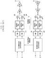
- FIG. 1 is a circuit diagram illustrating a configuration of the conventional transceiver for I/O mismatch calibration.
- the transceiver includes an envelope detector 150 between up-converters 123 and 125 of the RF unit and Analog To Digital Converters (ADCs) 135 and 137 of the receiver and is configured to cancel the I/Q mismatch of the transmitter and leakage of the LO of the transmitter.
- the transmitter may generate a tone to the Radio Frequency (RF) unit via Digital To Analog Converters (DACs) 115 and 117.
- RF Radio Frequency
- DACs Digital To Analog Converters
- the envelope detector 150 is included in the RF unit as an extra component for I/Q mismatch calibration. Furthermore, the envelope detector 150 cannot be used to estimate the receiver I/Q mismatch. This means a need of a separate structure or algorithm to estimate the receiver I/Q mismatch.
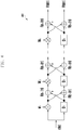
- FIG. 2 is a circuit diagram illustrating a configuration of another conventional transceiver for I/Q mismatch calibration.
- the transceiver includes a phase shifter 250 between up-converters 223 and 225 of the transmitter of the RF unit and down converters 243 and 245 of the receiver to cancel the I/Q mismatch of the transmitter.
- the phase shifter 250 can estimate I/Q mismatches of both the transmitter and receiver using a training sequence received at the receiver through the loopback path at angles of 0 and 90 degrees.
- phase shifter 250 As an extra component in the RF unit for I/Q mismatch calibration, similar to the transceiver of FIG. 1 .
- three or more different training sequences are, typically, required.
- This transceiver also has a drawback of large amount of calculation for estimating the I/Q mismatch.
- An embodiment of the present invention provides a loopback path capable of being implemented for I/Q mismatch calibration and a training sequence suited for I/Q mismatch using the loopback path.
- a description is made herein of the algorithm and transceiver configuration for estimating I/Q mismatch, with small calculation amount, using the loopback path and training sequence, according to an embodiment of the present invention.
- FIG. 3 is a circuit diagram illustrating a configuration of a transceiver for I/Q mismatch calibration, according to an embodiment of the present invention
- FIG. 4 is a circuit diagram illustrating a configuration of a Golay Correlator, according to an embodiment of the present invention
- FIG. 5 is a circuit diagram illustrating an I/Q mismatch compensator, according to an embodiment of the present invention.
- a transmitter of the transceiver 300 includes a transmitter baseband unit 311, a transmitter I/Q mismatch compensator 313, Digital To Analog Converters (DACs) 315 and 317, amplifier/filter units 319 and 321, up-converters 323 and 325, a Variable Gain Amplifier (VGA) 327, a Power Amplifier (PA), and a transmit antenna 329-1.
- DACs Digital To Analog Converters
- VGA Variable Gain Amplifier
- PA Power Amplifier
- the transmitter baseband unit 311 performs baseband modulation on the signal to be transmitted and generates a training sequence necessary for I/Q mismatch calibration.
- the transmitter baseband unit 311 may include a training sequence generator for generating the training sequence as a separate component.
- the transmitter I/Q mismatch compensator 313 compensates the transmission signal for the influence of I/Q mismatch using the I/Q mismatch estimation value of the transmitter.
- the DACs 315 and 317 are responsible for converting a digital signal to an analog signal, and the amplifier/filter units 319 and 321 perform amplifying and filtering on the analog transmission signal.
- the up-converters 323 and 325 up-convert a baseband signal to a passband signal.
- the VGA 327 adjusts the transmit power of the transmitter, and the PA 329 amplifies the transmission signal to a high power level for transmission through the transmit antenna 329-1.
- the training sequence generator generates a binary sequence having a good correlation characteristic.
- the binary sequence may be the Golay sequence specified in the IEEE 802.11ad, a Constant Amplitude Zero Auto-Correlation (CAZAC) sequence, or a Walsh-Hadamard sequence specified in the Long-Term Evolution (LTE) standard, but not limited thereto.
- the training sequence generator stores the binary sequence in a Read Only memory (ROM) and reads it from the ROM if necessary.
- ROM Read Only memory
- the receiver of the transceiver 300 includes a receive antenna 349-1, a Low Noise Amplifier (LNA) 349, a VGA 347, down-converters 343 and 345, amplifier/filter units 339 and 341, Analog-To-Digital Converters (ADCs) 335 and 337, a receiver I/Q mismatch compensator 333, and a receiver baseband unit 331.
- the receiver further includes a correlator 350 and an I/Q mismatch estimator 360.
- the LNA 349 is responsible for canceling noise of the received signal, and the VGA 347 amplifies the received signal to an appropriate power level.
- the down-converters 343 and 345 convert a passband signal to the baseband signal, and the amplifier/filter units 339 and 341 amplify and filter the received signal.
- the ADCs 335 and 337 convert the analog signal to digital signal.
- the receiver I/Q mismatch compensator 333 compensates the received signal for the influence of the I/Q mismatch using the I/Q mismatch estimation value of the receiver.
- the correlator 350 on the training sequence and the I/Q mismatch estimator 360 calculate I/Q mismatches of the transmitter and receiver using a correlation value.
- the correlator 350 of the receiver matches the training sequence sent to the transmitter and outputs the peak result value when the received signal completely matches the correlator 350.
- the correlator can be implemented soley with adders but not multipliers, e.g., in the case of using a binary sequence as the training sequence. This is advantageous in terms of small calculation amount, and the calculation amount may further decreased by using the Golay correlator 450, as configured in FIG. 4 . A detailed description of the configuration and operation of the Golay correlator 450 is omitted herein.
- the transmitter I/Q mismatch compensator 313 and the receiver I/Q mismatch compensator 333 receive the I/Q mismatch estimation values of the transmitter and the receiver from the I/Q mismatch estimator 360.
- the transmitter I/Q mismatch compensator 313 removes the I/Q mismatch influence of the transmission signal.
- the receiver I/Q mismatch compensator 333 removes the I/Q mismatch influence of the received signal, as described below.
- the transceiver 300 uses two or more loopback paths for connecting the transmitter and receiver in the RF unit in order to estimate I/Q mismatch.
- the loopback path may be implemented by connecting a module output of the transmitter and a module input of the receiver from among the modules constituting the RF unit. Alternatively, it is possible to configure two loopback paths by connecting the module output of different transmitters and the module input of the receiver.
- the first loopback path may be established by connecting the output node of the up-converters 323 and 325 to the input nodes of the down-converters 339 and 341.
- the second loopback path may be established by connecting the output node of the VGA 327 of the transmitter and the input node of the VGA 347 of the receiver.
- the loopback paths include the switches 370 and 375 respectively. That is, the first loopback path includes the first switch 370, and the second loopback path includes the second switch 375.
- the loopback paths are established or cut off by turning on/off the first and second switches 370 and 375.
- the training sequence may be received through the first loopback path, which is established by turning on the first switch 370 and off the second switch 375, or through the second loopback path, which is established by turning off the first switch 370 and on the second switch 375.
- a description of another embodiment of establishing two or more loopback paths connecting the transmitter and the receiver in the RF unit for I/Q mismatch estimation of the transceiver is made with reference to FIG. 6 .
- FIG. 6 is a circuit diagram illustrating a configuration of the transceiver for I/Q mismatch calibration, according to another embodiment of the present invention.
- the transmitter of the transceiver 600 includes a transmitter baseband unit 611, a transmitter I/Q mismatch compensator 613, DACs 615 and 617, amplifier/filter units 619 and 621, up-converters 623 and 625, a VGA 627, a PA 629, and a transmit antenna 629-1.
- DACs 615 and 617 include DACs 615 and 617, amplifier/filter units 619 and 621, up-converters 623 and 625, a VGA 627, a PA 629, and a transmit antenna 629-1.
- the receiver of the transceiver 600 includes a receive antenna 649-1, an LNA 649, a VGA 647, down converters 643 and 645, amplifier/filter units 639 and 641, ADCs 635 and 637, a receiver I/Q mismatch compensator 633, and a receiver baseband unit 631.
- the receiver further includes a correlator 650 and an I/Q mismatch estimator 660.
- the transceiver 300 includes two or more loopback paths which connect the transmitter and the receiver in the RF unit for I/Q mismatch estimation. As shown in FIG. 6 , different versions of an output of the transmitter are input to the multiplexer (Mux) 670, and the output of the Mux 670 is connected to the receiver.
- the Mux 670 is capable of changing one input selectively to implement two loopback paths.
- the transceiver is not limited to the configurations as described above and can be implemented in different configurations.
- the description is directed to the case where the correlator is included in the receiver, the correlator may be included in the transmitter.
- the I/Q mismatch calibration operation of the RF transceiver is described with reference to the transceiver 300 of FIG. 3 .
- the first loopback path is established between the transmitter and the receiver by turning on the switch 370 and turning off the switch 375 in the RF unit.
- the baseband unit 311 of the transmitter generates a training sequence necessary for I/Q mismatch calibration.
- the training sequence may be generated by a training sequence generator included in the baseband unit 311 of the transmitter.
- the training sequence may be a binary sequence.
- the training sequence is transferred to the DACs 315 and 317.
- the receiver correlates the training sequence received from the ADCs 335 and 337 via the correlator 350 to output the result value to the I/Q mismatch estimator 360.
- the first loopback path is cut off, and the second loopback path is established between the transmitter and the receiver. That is, the first switch 370 turns off, and the second switch 375 turns on to establish the second loopback path between the transmitter and the receiver.
- the baseband unit 311 of the transmitter generates a training sequence which is identical to the training sequence transmitted through the first loopback path.
- the training sequence generator included in the baseband unit 311 of the transmitter generates the training sequence, which is identical with the training sequence transmitted through the first loopback path.
- the training sequence is sent to the receiver through the second loopback path and the ADCs 335 and 337.
- the ADCs 335 and 337 send the training sequence to the correlator 350, which performs correlation and sends the resultant value to the I/Q mismatch estimator 360.
- the I/Q mismatch estimator 360 estimates the transmitter gain mismatch, transmitter phase mismatch, receiver gain mismatch, and receiver phase mismatch using the correlation value of the training sequence received through the two loopback paths, as described below.
- the estimated transmitter gain and phase mismatch values are transferred to the I/Q mismatch compensator 313 of the transmitter.
- the I/Q mismatch compensator 313 of the transmitter removes the I/Q mismatch influence of the transmitter using the transmitter gain and phase mismatch values.
- the estimated receiver gain and phase mismatch values are transferred to the I/Q mismatch compensator 333 of the receiver.
- the I/Q mismatch compensator 333 of the receiver removes the I/Q mismatch influence of the receiver using the receiver gain and phase mismatch values.
- the I/Q mismatch calibration operation of the transceiver may be implemented using the Mux 670, as shown in FIG. 6 . That is, the Mux 670 is capable of establishing two or more loopback paths by switching between the inputs to transfer the same training sequence through the respective loopback paths, thereby obtaining the same effect of using the two switches 370 and 375.
- the transceiver 300 (or 600) establishes the first loopback path between the transmitter and the receiver in order for the transmitter training sequence generator to transmit the training sequence.
- the transceiver establishes the second loopback path between the transmitter and the receiver in order for the transmitter training sequence generator to transmit the training sequence.
- the complex-conjugated signal x* occurs as self-interference to the original signal x so as to degrades the EVM of the received signal.
- Equation (4) shows the correlation mathematically and can be implemented as a correlator suitable for the training sequence.
- Golay sequence As the training sequence, it is possible to implement the correlator with small calculation amount using the Golay correlator.
- CAZAC sequence or Walsh-Hadamard sequence it is possible to implement the correlator in similar ways.
- Equations (3) and (4) it is possible to calculate cos ⁇ 1, sin ⁇ 1, cos ⁇ 2, and sin ⁇ 2 as shown in Equations (5) to (8):
- ⁇ Tx, ⁇ Tx, ⁇ Rx, and ⁇ Rx can be estimated through Equation (14), using cos ⁇ 1, sin ⁇ 1, cos ⁇ 2, and sin ⁇ 2 obtained by Equations (5) to (8), as shown below:
- ⁇ Tx ⁇ Rx ⁇ Tx ⁇ Rx cos ⁇ 1 cos ⁇ 1 ⁇ sin ⁇ 1 sin ⁇ 1 sin ⁇ 1 ⁇ sin ⁇ 1 cos ⁇ 1 cos ⁇ 1 cos ⁇ 2 cos ⁇ 2 ⁇ sin ⁇ 2 sin ⁇ 2 sin ⁇ 2 sin ⁇ 2 sin ⁇ 2 sin ⁇ 2 sin ⁇ 2 cos ⁇ 2 cos ⁇ 2 ⁇ 1 ⁇ A B C D
- the I/Q mismatch estimation obtains cos ⁇ 1, sin ⁇ 1, cos ⁇ 2, and sin ⁇ 2 by correlating the training sequence signal known at the receiver to the received training sequence. It is possible to calculate the I/Q mismatch through a simple matrix operation using the value obtained by correlating the complex conjugate signal of the training sequence and the cos ⁇ 1, sin ⁇ 1, cos ⁇ 2, and sin ⁇ 2.
- the I/Q mismatch estimation algorithm in accordance with the present invention, is capable of estimating the I/Q mismatch independently of the size of the received signal.
- the correlation can be performed using the Golay Sequence.
- the CAZAC sequence or the Walsh-Hadamard sequence as the training sequence, it is possible to design the correlator structure matching the corresponding sequence.
- the correlation can be calculated using addition, without using multiplication.
- Table 1 shows the difference in calculation amount according to the length of the training sequence between the transceiver of FIG. 2 , which uses the phase shifter and the transceiver, according to an embodiment of the present invention.
- Table 1 Multiplication Addition Transceiver implemented with Phase Shifter N*6 (N+1)*6 Transceiver implemented according to an embodiment of the present invention - 512*8
- the number of multiplication operations increases in proportion to the training sequence length N in the case of the transceiver implemented with the phase shift.
- the transceiver according to an embodiment of the present invention uses only addition without multiplication.
- the correlator can be used for both baseband synchronization and channel estimation.
- the correlator can be implemented in hardware or software.
- the function of calculating the cos ⁇ 1, sin ⁇ 1, cos ⁇ 2, and sin ⁇ 2 using the correlation output value may be more efficient in the case of being implemented in software in view of implementation flexibility.
- the hardware implementation is also possible in consideration of the estimation speed.
- the ⁇ Tx, ⁇ Tx, ⁇ Rx, and ⁇ Rx, estimated as above, are transferred to the I/Q mismatch compensator 313 (613) of the transmitter and the I/Q mismatch compensator 333 (633) of the receiver to compensate for the gain and phase mismatches of the transmitter and receiver.
- the I/Q mismatch compensators 313 (613) and 333 (633) can be implemented as shown in FIG. 5 .
- the I/Q mismatch compensator 313, 333, 613, and 633 can be implemented in hardware in consideration of the system speed.
- the transceiver 300 may include a control unit for controlling the overall operations of the transceiver.
- the control unit may control the transceiver to execute the operation of one of the above described embodiments.
- the control unit may control the baseband unit to generate the training sequence and may control the switch or multiplexer to establish the first and/or second loopback paths.
- the control unit also may control the correlator to perform correlation using the received training sequence and control the I/Q mismatch estimator to calculate the I/Q mismatches of the transmitter and the receiver using the correlation value.
- the I/Q mismatch calibration method is capable of implementing the loopback path between the transmitter and the receiver in the RF.
- the transceiver according to an embodiment of the present invention is capable of establishing two loopback paths simply with switches or a Mux. This means that it is possible to simplify the implementation and inspection of the RF unit and reduce the size of the RF unit.
- the I/Q mismatch calibration method of the present invention is advantageous in terms of reducing the calculation amount required for I/Q mismatch calibration.
- the correlator proposed in the present invention can be configured for use in baseband synchronization and channel estimation so as to reduce the load of software and the size of the flash memory for storing software code.
- the I/Q mismatch calibration method and apparatus of the present invention is advantageous in terms of implementing the loopback path inside the RF module without extra device, e.g., an envelope detector or a phase shifter.
- the I/Q mismatch calibration method and apparatus of the present invention is advantageous in terms of making it possible to reduce the hardware gate size and/or software code size due to the reduced calculation amount of the I/Q mismatch estimation algorithm.
- the I/Q mismatch calibration method and apparatus of the present invention is advantageous in terms of reducing the form factor of the chip on which the transceiver is disposed.
- the I/Q mismatch calibration method and apparatus of the present invention is advantageous in terms of facilitating I/Q mismatch calibration by reducing the calculation amount and/or time of the algorithm and by estimating the I/Q mismatch using only the training sequence transmission twice.
- the I/Q mismatch calibration method and apparatus of the present invention is advantageous in terms of reducing the boot-up time by minimizing the I/Q mismatch calibration time on the initialization of the communication system.
Landscapes
- Engineering & Computer Science (AREA)
- Computer Networks & Wireless Communication (AREA)
- Signal Processing (AREA)
- Physics & Mathematics (AREA)
- Electromagnetism (AREA)
- Power Engineering (AREA)
- Transceivers (AREA)
Description
- The present invention relates generally to an In-Phase/Quadrature Phase (I/Q) mismatch calibration method and apparatus, and more particularly, to a transceiver for use in any of Wireless Local Area Network (WLAN), Wireless Personal Area Network (PAN), and 3rd Generation (3G) and 4G cellular mobile communication systems.
- A mobile communication system can adopt Quadrature Modulation which uses orthogonal In-Phase (I) and Quadrature Phase (Q) simultaneously for up-conversion of a signal from baseband to passband and down-conversion from passband to baseband. The quadrature modulation is advantageous in terms of two-fold increase of transmission on a single carrier but disadvantageous in that a mismatch between the In-Phase and Quadrature Phase of the Local Oscillator (LO) causes mutual interference between I-phase and Q-phase signals and, thus, degrades system performance.
- The I/Q mismatch may be divided into two categories, gain mismatch and phase mismatch. The gain mismatch denotes the difference in magnitude between I and Q components of the LO. The phase mismatch denotes the loss of the orthogonality in phase between I and Q components.
- If the I/Q mismatch occurs at the quadrature modulator of a transceiver, this degrades Error Vector Magnitude (EVM) and increases Packet Error Rate (PER), resulting in degradation of entire system. Particularly, radio communication systems such as WLAN, WPAN, 3G, and 4G cellular communication systems adopt high order modulation schemes including 16 Quadrature Amplitude Modulation (QAM), 64QAM, and 256QAM, which requires calibration of the transceiver I/Q due to the I/Q mismatch, i.e., the radio communication systems become more sensitive to the transceiver I/Q mismatch as the modulation order increases.
-
US 2004/219884 A1 discloses a switch which enables a feedback loop between the transmitter and the receiver, and a switch, which is used for transmitter and receiver I/Q mismatch measurement, but which outputs the RF output of the transmitter from a driver, through the envelope detector, to the I-path at the receiver output, through the receiver buffer, and back to processor. This allows a calibration waveform sent to the transmitter to be amplitude demodulated by the envelope detector, bypass the receiver, and fed back to the processor, where the envelope of the RF signal is digitized by the ADC of the processor. The transmitter circuit generates RF training signals just like during an ordinary data transmission while the switch is closed to make the receive mismatch measurement loopback connection active. On the other hand, the switch is closed to make an appropriate loopback connection active, and a calibration waveform is sent to the transmitter so that the envelope of the waveform, provided by the envelope detector, is digitized by the ADC of the processor. -
WO 2013/011973 A1 discloses a feedback path from the output side of a quadrature modulator to the input side of a quadrature demodulator. - The present invention has been made to address at least the problems and/or disadvantages described above and to provide at least the advantages described below. The scope of protection is defined by the claims. Any embodiments which do not fall within the scope of the claims are considered to be examples.
- In accordance with an aspect of the present invention, an In-phase/Quadrature phase (I/Q) mismatch compensation method of a transceiver is provided. The method includes establishing a first loopback path between a transmitter and a receiver, transmitting a training sequence from the transmitter to the receiver through the established first loopback path, acquiring, at the receiver, a first correlation result value by correlating the training sequence received through the established first loopback path, establishing a second loopback path between the transmitter and the receiver, transmitting the training sequence from the transmitter to the receiver through the established second loopback path, acquiring, at the receiver, a second correlation result value by correlating the training sequence received through the second loopback path, and estimating I/Q mismatch values of the transmitter and the receiver using the first and second correlation result values.
- In accordance with another aspect of the present invention, a transceiver for compensating for In-phase/Quadrature phase (I/Q) mismatch is provided. The transceiver includes a transmitter configured to generate a training sequence, a receiver configured to estimate an I/Q mismatch value based on the generated training sequence, and a controller configured to control establishing a first loopback path between a transmitter and a receiver, transmitting the generated training sequence from the transmitter to the receiver through the established first loopback path, acquiring, at the receiver, a first correlation result value by correlating the generated training sequence received through the established first loopback path, establishing a second loopback path between the transmitter and the receiver, transmitting the generated training sequence from the transmitter to the receiver through the established second loopback path, acquiring, at the receiver, a second correlation result value by correlating the generated training sequence received through the established second loopback path, and estimating I/Q mismatch values of the transmitter and the receiver using the first and second correlation result values.
- The above and other aspects, features, and advantages of certain embodiments of the present invention will be more apparent from the following detailed description when read in conjunction with the accompanying drawings, in which:
-
FIG. 1 is a circuit diagram illustrating a configuration of a conventional transceiver for I/O mismatch calibration; -
FIG. 2 is a circuit diagram illustrating a configuration of another conventional transceiver for I/Q mismatch calibration; -
FIG. 3 is a circuit diagram illustrating a configuration of a transceiver for I/Q mismatch calibration, according to an embodiment of the present invention; -
FIG. 4 is a circuit diagram illustrating a configuration of a Golay Correlator, according to an embodiment of the present invention; -
FIG. 5 is a circuit diagram illustrating an I/Q mismatch compensator, according to an embodiment of the present invention; and -
FIG. 6 is a circuit diagram illustrating a configuration of the transceiver for I/Q mismatch calibration, according to another embodiment of the present invention. - One or more embodiments of the present invention will now be described more fully with reference to the accompanying drawings, in which embodiments of the invention are shown. The invention may, however, be embodied in many different forms, and should not be construed as being limited to the embodiments set forth herein. Thus, the invention may include all revisions, equivalents, or substitutions which are included in the concept and the technical scope related to the invention.
- Although the description is directed to the IEEE 802.11ad communication access technology, it will be understood by those skilled in the art that the present invention can be applied to other communication systems having a similar technical background and channel format, with a slight modification, without departing from the scope of the present invention.
-
FIG. 1 is a circuit diagram illustrating a configuration of the conventional transceiver for I/O mismatch calibration. - Referring to
FIG. 1 , the transceiver includes anenvelope detector 150 between up-converters ADCs envelop detector 150 which allows the transceiver to estimate transmitter I/Q mismatch based on signal. - In this case, however, the
envelope detector 150 is included in the RF unit as an extra component for I/Q mismatch calibration. Furthermore, theenvelope detector 150 cannot be used to estimate the receiver I/Q mismatch. This means a need of a separate structure or algorithm to estimate the receiver I/Q mismatch. -
FIG. 2 is a circuit diagram illustrating a configuration of another conventional transceiver for I/Q mismatch calibration. - Referring to
FIG. 2 , the transceiver includes aphase shifter 250 between up-converters converters phase shifter 250 can estimate I/Q mismatches of both the transmitter and receiver using a training sequence received at the receiver through the loopback path at angles of 0 and 90 degrees. - Even in this case, there is a need of the
phase shifter 250 as an extra component in the RF unit for I/Q mismatch calibration, similar to the transceiver ofFIG. 1 . In order to estimate the I/Q mismatch, three or more different training sequences are, typically, required. This transceiver also has a drawback of large amount of calculation for estimating the I/Q mismatch. - An embodiment of the present invention provides a loopback path capable of being implemented for I/Q mismatch calibration and a training sequence suited for I/Q mismatch using the loopback path. A description is made herein of the algorithm and transceiver configuration for estimating I/Q mismatch, with small calculation amount, using the loopback path and training sequence, according to an embodiment of the present invention.
-
FIG. 3 is a circuit diagram illustrating a configuration of a transceiver for I/Q mismatch calibration, according to an embodiment of the present invention,FIG. 4 is a circuit diagram illustrating a configuration of a Golay Correlator, according to an embodiment of the present invention, andFIG. 5 is a circuit diagram illustrating an I/Q mismatch compensator, according to an embodiment of the present invention. - Referring to
FIG. 3 , a transmitter of the transceiver 300, according to an embodiment of the present invention, includes atransmitter baseband unit 311, a transmitter I/Q mismatch compensator 313, Digital To Analog Converters (DACs) 315 and 317, amplifier/filter units converters - The
transmitter baseband unit 311 performs baseband modulation on the signal to be transmitted and generates a training sequence necessary for I/Q mismatch calibration. Thetransmitter baseband unit 311 may include a training sequence generator for generating the training sequence as a separate component. - The transmitter I/
Q mismatch compensator 313 compensates the transmission signal for the influence of I/Q mismatch using the I/Q mismatch estimation value of the transmitter. - The
DACs filter units converters - The
VGA 327 adjusts the transmit power of the transmitter, and thePA 329 amplifies the transmission signal to a high power level for transmission through the transmit antenna 329-1. - The training sequence generator generates a binary sequence having a good correlation characteristic. The binary sequence may be the Golay sequence specified in the IEEE 802.11ad, a Constant Amplitude Zero Auto-Correlation (CAZAC) sequence, or a Walsh-Hadamard sequence specified in the Long-Term Evolution (LTE) standard, but not limited thereto. For example, the training sequence generator stores the binary sequence in a Read Only memory (ROM) and reads it from the ROM if necessary.
- The receiver of the transceiver 300 includes a receive antenna 349-1, a Low Noise Amplifier (LNA) 349, a
VGA 347, down-converters filter units Q mismatch compensator 333, and areceiver baseband unit 331. The receiver further includes acorrelator 350 and an I/Q mismatch estimator 360. - The
LNA 349 is responsible for canceling noise of the received signal, and theVGA 347 amplifies the received signal to an appropriate power level. - The down-
converters filter units ADCs - The receiver I/
Q mismatch compensator 333 compensates the received signal for the influence of the I/Q mismatch using the I/Q mismatch estimation value of the receiver. - The
correlator 350 on the training sequence and the I/Q mismatch estimator 360 calculate I/Q mismatches of the transmitter and receiver using a correlation value. Thecorrelator 350 of the receiver matches the training sequence sent to the transmitter and outputs the peak result value when the received signal completely matches thecorrelator 350. The correlator can be implemented soley with adders but not multipliers, e.g., in the case of using a binary sequence as the training sequence. This is advantageous in terms of small calculation amount, and the calculation amount may further decreased by using the Golay correlator 450, as configured inFIG. 4 . A detailed description of the configuration and operation of the Golay correlator 450 is omitted herein. - The transmitter I/
Q mismatch compensator 313 and the receiver I/Q mismatch compensator 333 receive the I/Q mismatch estimation values of the transmitter and the receiver from the I/Q mismatch estimator 360. The transmitter I/Q mismatch compensator 313 removes the I/Q mismatch influence of the transmission signal. Also, the receiver I/Q mismatch compensator 333 removes the I/Q mismatch influence of the received signal, as described below. - The transceiver 300 uses two or more loopback paths for connecting the transmitter and receiver in the RF unit in order to estimate I/Q mismatch. The loopback path may be implemented by connecting a module output of the transmitter and a module input of the receiver from among the modules constituting the RF unit. Alternatively, it is possible to configure two loopback paths by connecting the module output of different transmitters and the module input of the receiver.
- The first loopback path may be established by connecting the output node of the up-
converters converters VGA 327 of the transmitter and the input node of theVGA 347 of the receiver. The loopback paths include theswitches first switch 370, and the second loopback path includes thesecond switch 375. The loopback paths are established or cut off by turning on/off the first andsecond switches first switch 370 and off thesecond switch 375, or through the second loopback path, which is established by turning off thefirst switch 370 and on thesecond switch 375. - A description of another embodiment of establishing two or more loopback paths connecting the transmitter and the receiver in the RF unit for I/Q mismatch estimation of the transceiver is made with reference to
FIG. 6 . -
FIG. 6 is a circuit diagram illustrating a configuration of the transceiver for I/Q mismatch calibration, according to another embodiment of the present invention. - The transmitter of the transceiver 600 includes a
transmitter baseband unit 611, a transmitter I/Q mismatch compensator 613,DACs filter units converters PA 629, and a transmit antenna 629-1. A detailed description of the operations of the components of the transmitter illustrated inFIG. 6 , which are identical to those of the transmitter inFIG. 3 , is omitted herein. - The receiver of the transceiver 600 includes a receive antenna 649-1, an
LNA 649, aVGA 647, downconverters filter units ADCs Q mismatch compensator 633, and areceiver baseband unit 631. The receiver further includes acorrelator 650 and an I/Q mismatch estimator 660. A detailed description of the operations of the components of the receiver illustrated inFIG. 6 , which are identical to those of the receiver inFIG. 3 , is omitted herein. - The transceiver 300 includes two or more loopback paths which connect the transmitter and the receiver in the RF unit for I/Q mismatch estimation. As shown in
FIG. 6 , different versions of an output of the transmitter are input to the multiplexer (Mux) 670, and the output of theMux 670 is connected to the receiver. TheMux 670 is capable of changing one input selectively to implement two loopback paths. - The transceiver is not limited to the configurations as described above and can be implemented in different configurations. For example, although the description is directed to the case where the correlator is included in the receiver, the correlator may be included in the transmitter.
- The I/Q mismatch calibration operation of the RF transceiver, according to an embodiment of the present invention, is described with reference to the transceiver 300 of
FIG. 3 . - The first loopback path is established between the transmitter and the receiver by turning on the
switch 370 and turning off theswitch 375 in the RF unit. - Next, the
baseband unit 311 of the transmitter generates a training sequence necessary for I/Q mismatch calibration. The training sequence may be generated by a training sequence generator included in thebaseband unit 311 of the transmitter. As described above, the training sequence may be a binary sequence. - The training sequence is transferred to the
DACs ADCs correlator 350 to output the result value to the I/Q mismatch estimator 360. - If the first correlation has been completed, the first loopback path is cut off, and the second loopback path is established between the transmitter and the receiver. That is, the
first switch 370 turns off, and thesecond switch 375 turns on to establish the second loopback path between the transmitter and the receiver. - Next, the
baseband unit 311 of the transmitter generates a training sequence which is identical to the training sequence transmitted through the first loopback path. The training sequence generator included in thebaseband unit 311 of the transmitter generates the training sequence, which is identical with the training sequence transmitted through the first loopback path. - The training sequence is sent to the receiver through the second loopback path and the
ADCs ADCs correlator 350, which performs correlation and sends the resultant value to the I/Q mismatch estimator 360. - Next, the I/
Q mismatch estimator 360 estimates the transmitter gain mismatch, transmitter phase mismatch, receiver gain mismatch, and receiver phase mismatch using the correlation value of the training sequence received through the two loopback paths, as described below. - The estimated transmitter gain and phase mismatch values are transferred to the I/
Q mismatch compensator 313 of the transmitter. Next, the I/Q mismatch compensator 313 of the transmitter removes the I/Q mismatch influence of the transmitter using the transmitter gain and phase mismatch values. - Likewise, the estimated receiver gain and phase mismatch values are transferred to the I/
Q mismatch compensator 333 of the receiver. Next, the I/Q mismatch compensator 333 of the receiver removes the I/Q mismatch influence of the receiver using the receiver gain and phase mismatch values. - The I/Q mismatch calibration operation of the transceiver, according to an embodiment of the present invention, may be implemented using the
Mux 670, as shown inFIG. 6 . That is, theMux 670 is capable of establishing two or more loopback paths by switching between the inputs to transfer the same training sequence through the respective loopback paths, thereby obtaining the same effect of using the twoswitches - A description of the I/Q mismatch estimation operation, according to an embodiment of the present invention is now described.
- The transceiver 300 (or 600) establishes the first loopback path between the transmitter and the receiver in order for the transmitter training sequence generator to transmit the training sequence. At this time, the signal r1 received by the receiver through the first loopback path can be expressed as Equation (1):

where x denotes the transmitted training sequence, and εTx, θTx, εRx, and θRx denote transmitter gain and phase mismatches and receiver gain and phase mismatches respectively. Also, φ1 denotes the phase delay of the training sequence received through the first loopback path of the RF unit. - The transceiver establishes the second loopback path between the transmitter and the receiver in order for the transmitter training sequence generator to transmit the training sequence. At this time, the signal r2 received by the receiver through the second loopback path can be expressed as Equation (2):

where φ2 denotes the phase delay of the training sequence received through the second loopback path of the RF unit, x denotes the transmitted training sequence, and εTx, θTx, εRx, and θRx denote transmitter gain and phase mismatches and receiver gain and phase mismatches respectively. - From Equations (1) and (2), if there is I/Q mismatch between the transmitter and the receiver, the complex-conjugated signal x* occurs as self-interference to the original signal x so as to degrades the EVM of the received signal.
- In order to estimate the I/Q mismatch value using Equations (1) and (2), it is necessary to find φ1 and φ2, as well as εTx, θTx, εRx, and θRx. The training sequence for use in I/Q mismatch estimation is a Pseudo Random Noise Sequence (such as a Golay Sequence, a CAZAC sequence, and a Walsh-Hadamard Sequence) which uses Equations (3) and (4) for the sequence length N, as shown below:


- Equation (4) shows the correlation mathematically and can be implemented as a correlator suitable for the training sequence. When using the Golay sequence as the training sequence, it is possible to implement the correlator with small calculation amount using the Golay correlator. When using the CAZAC sequence or Walsh-Hadamard sequence, it is possible to implement the correlator in similar ways.
- Using Equations (3) and (4), it is possible to calculate cosϕ1, sinϕ1, cosϕ2, and sinϕ2 as shown in Equations (5) to (8):



- Also, using εTx, θTx, εRx, and θRx , it is possible to express εTx, θTx, εRx, and θRx as shown in Equations (9) to (12):


- This can be expressed in the form of a matrix as Equation (13):

- Accordingly, εTx, θTx, εRx, and θRx can be estimated through Equation (14), using cosϕ1, sinϕ1, cosϕ2, and sinϕ2 obtained by Equations (5) to (8), as shown below:

- That is, the I/Q mismatch estimation, according to the present invention, obtains cosϕ1, sinϕ1, cosϕ2, and sinϕ2 by correlating the training sequence signal known at the receiver to the received training sequence. It is possible to calculate the I/Q mismatch through a simple matrix operation using the value obtained by correlating the complex conjugate signal of the training sequence and the cosϕ1, sinϕ1, cosϕ2, and sinϕ2.
- Since the training sequences pass through a different number of modules, which have different gains in the RF unit, the received training sequences are different in size. However, the I/Q mismatch estimation algorithm, in accordance with the present invention, is capable of estimating the I/Q mismatch independently of the size of the received signal.
- Meanwhile, in the case of using the Golay Sequence, e.g., for use in the IEEE 802.11ad, the correlation can be performed using the Golay Sequence. In the case of using the CAZAC sequence or the Walsh-Hadamard sequence as the training sequence, it is possible to design the correlator structure matching the corresponding sequence.
- Since the training sequences are of the binary type, the correlation can be calculated using addition, without using multiplication.
- Table 1 shows the difference in calculation amount according to the length of the training sequence between the transceiver of
FIG. 2 , which uses the phase shifter and the transceiver, according to an embodiment of the present invention.Table 1 Multiplication Addition Transceiver implemented with Phase Shifter N*6 (N+1)*6 Transceiver implemented according to an embodiment of the present invention - 512*8 - As shown in Table 1, the number of multiplication operations increases in proportion to the training sequence length N in the case of the transceiver implemented with the phase shift. The transceiver according to an embodiment of the present invention uses only addition without multiplication.
- The correlator can be used for both baseband synchronization and channel estimation. The correlator can be implemented in hardware or software. The function of calculating the cosϕ1, sinϕ1, cosϕ2, and sinϕ2 using the correlation output value may be more efficient in the case of being implemented in software in view of implementation flexibility. However, the hardware implementation is also possible in consideration of the estimation speed.
- The εTx, θTx, εRx, and θRx, estimated as above, are transferred to the I/Q mismatch compensator 313 (613) of the transmitter and the I/Q mismatch compensator 333 (633) of the receiver to compensate for the gain and phase mismatches of the transmitter and receiver. The I/Q mismatch compensators 313 (613) and 333 (633) can be implemented as shown in
FIG. 5 . The I/Q mismatch compensator - Although not shown in the drawings, the transceiver 300 (600), according to an embodiment of the present invention, may include a control unit for controlling the overall operations of the transceiver. The control unit may control the transceiver to execute the operation of one of the above described embodiments. For example, the control unit may control the baseband unit to generate the training sequence and may control the switch or multiplexer to establish the first and/or second loopback paths. The control unit also may control the correlator to perform correlation using the received training sequence and control the I/Q mismatch estimator to calculate the I/Q mismatches of the transmitter and the receiver using the correlation value.
- The I/Q mismatch calibration method is capable of implementing the loopback path between the transmitter and the receiver in the RF. Unlike the technologies of
FIGS. 1 and2 , which require extra component such as an envelope detector or a phase shifter to establish the loopback path, the transceiver according to an embodiment of the present invention is capable of establishing two loopback paths simply with switches or a Mux. This means that it is possible to simplify the implementation and inspection of the RF unit and reduce the size of the RF unit. - From the view point of baseband, it is possible to estimate the I/Q mismatches of both the transmitter and receiver simultaneously using the correlator having relatively small calculation amount and matrix operation. That is, the I/Q mismatch calibration method of the present invention is advantageous in terms of reducing the calculation amount required for I/Q mismatch calibration.
- Also, the correlator proposed in the present invention can be configured for use in baseband synchronization and channel estimation so as to reduce the load of software and the size of the flash memory for storing software code.
- As described above, the I/Q mismatch calibration method and apparatus of the present invention is advantageous in terms of implementing the loopback path inside the RF module without extra device, e.g., an envelope detector or a phase shifter.
- Also, the I/Q mismatch calibration method and apparatus of the present invention is advantageous in terms of making it possible to reduce the hardware gate size and/or software code size due to the reduced calculation amount of the I/Q mismatch estimation algorithm.
- Moreover, the I/Q mismatch calibration method and apparatus of the present invention is advantageous in terms of reducing the form factor of the chip on which the transceiver is disposed.
- Further, the I/Q mismatch calibration method and apparatus of the present invention is advantageous in terms of facilitating I/Q mismatch calibration by reducing the calculation amount and/or time of the algorithm and by estimating the I/Q mismatch using only the training sequence transmission twice.
- Also, the I/Q mismatch calibration method and apparatus of the present invention is advantageous in terms of reducing the boot-up time by minimizing the I/Q mismatch calibration time on the initialization of the communication system.
- While one or more embodiments of the present invention have been described with reference to the figures, it will be understood by those of ordinary skill in the art that various changes in form and details may be made therein without departing from the scope of the present invention as defined by the following claims.
Claims (14)
- An In-phase/Quadrature phase, I/Q, mismatch compensation method of a transceiver, the method comprising:establishing a first loopback path between a transmitter and a receiver;transmitting a first training sequence from the transmitter to the receiver through the established first loopback path;acquiring, at the receiver, a first correlation result value by correlating the first training sequence received through the established first loopback path;establishing a second loopback path between the transmitter and the receiver;transmitting a second training sequence from the transmitter to the receiver through the established second loopback path;acquiring, at the receiver, a second correlation result value by correlating the second training sequence received through the second loopback path; andestimating I/Q mismatch values of the transmitter and the receiver using the first and second correlation result values,wherein the first loopback path is established by turning on a first switch interposed between an output node of a first module of the transmitter and an input node of a first module of the receiver and turning off a second switch interposed between an output node of a second module of the transmitter and an input node of a second module of the receiver, and the second loopback path is established by turning off the first switch and turning on the second switch.
- The method of claim 1, wherein the first and second training sequence is a binary sequence.
- The method of claim 1,
wherein the first module of the transmitter, the second module of the transmitter, the first module of the receiver, and the second module of the receiver are among modules constituting a radio-frequency unit of the transceiver. - The method of claim 1, wherein the first and second loopback paths are established selectively by controlling a multiplexer interposed between at least two output nodes of the transmitter and at least one input node of the receiver.
- The method of claim 1, wherein estimating the I/Q mismatch values comprises:transmitting the first and second correlation result values to a correlator of the receiver;estimating gain and phase mismatch values of the transmitter and gain and phase mismatch values of the receiver using the first and second correlation result values; andtransmitting the estimated gain and phase mismatch values of the transmitter to a transmitter I/Q mismatch compensator of the transmitter and the gain and phase mismatch values of the receiver to a receiver I/Q mismatch compensator of the receiver.
- The method of claim 2, wherein the binary sequence is one of a Golay sequence, a Constant Amplitude Zero Auto-Correlation "CAZAC" sequence, and a Walsh-Hadamard sequence, and
wherein the first and second correlation result values are acquired from a 08.01.2016 correlator of the receiver. - The method of claim 1, wherein estimating the I/Q mismatch values comprises:estimating the I/Q mismatch values of the transmitter and the receiver using:
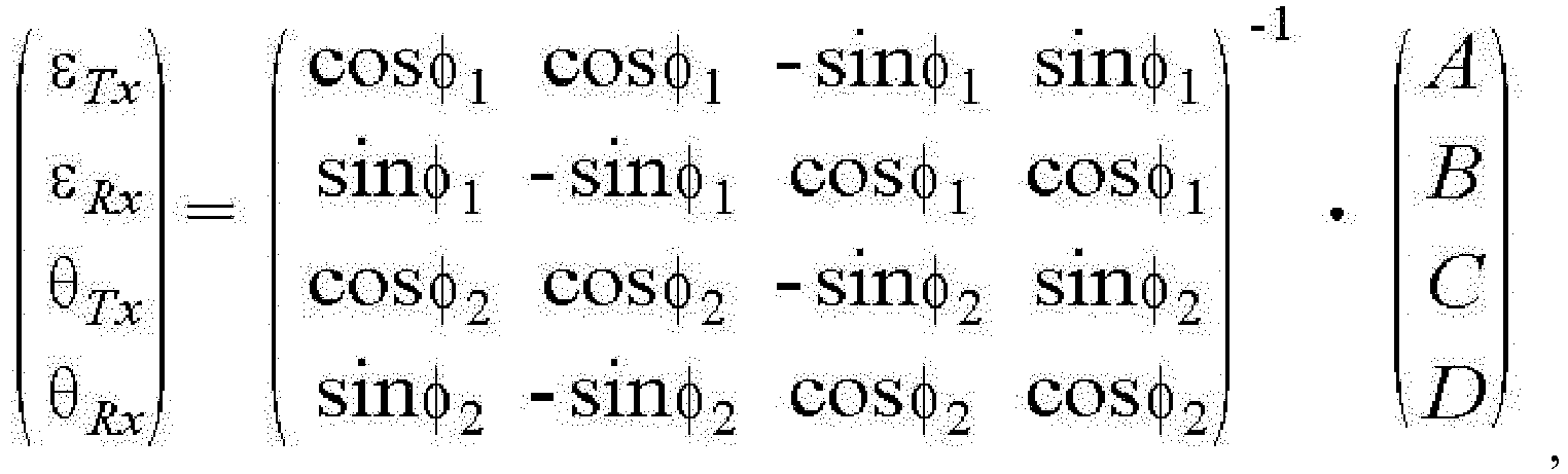 where εTx, θTx, εRx, and θRx denote transmitter gain and phase mismatches and receiver gain and phase mismatches respectively, φ1 denotes phase delay of the first training sequence received through the established first loopback path of a Radio Frequency (RF) unit, and φ2 denotes a phase delay of the second training sequence received through the established second loopback path of the RF unit, andwherein A and B are calculated using the first training sequence received through the established first loopback path and the training sequence generated at the transmitter, and C and D are calculated using the second training sequence received through the established second loopback path and the training sequence generated at the transmitter.
 - A transceiver for compensating for In-phase/Quadrature phase (I/Q) mismatch, the transceiver comprising:a transmitter (311) configured to generate a first and second training sequence;a receiver (331) configured to estimate an I/Q mismatch value based on the generated first and second training sequence;a controller configured to control establishing a first loopback path between a transmitter and a receiver, transmitting the generated first training sequence from the transmitter to the receiver through the established first loopback path, acquiring, at the receiver, a first correlation result value by correlating the generated first training sequence received through the established first loopback path, establishing a second loopback path between the transmitter and the receiver, transmitting the generated second training sequence from the transmitter to the receiver through the established second loopback path, acquiring, at the receiver, a second correlation result value by correlating the generated second training sequence received through the established second loopback path, and estimating I/Q mismatch values of the transmitter and the receiver using the first and second correlation result values;a first switch (370) interposed between an output node of a first module (323, 325) of the transmitter and an input node of a first module (343, 345) of the receiver; anda second switch (375) interposed between an output node of a second module (327)of the transmitter and an input node of a second module (347) of the receiver,wherein the controller is configured to control the first switch (370) to turn on and the second switch (375) to turn off to establish the first loopback path and to control the first switch (370) to turn off and the second switch (375) to turn on to establish the second loopback path.
- The transceiver of claim 8, wherein the first and second training sequence is a binary sequence.
- The transceiver of claim 8, wherein the first module of the transmitter, the second module of the transmitter, the first module of the receiver, and the second module of the receiver are among modules constituting a radio-frequency unit of the transceiver.
- The transceiver of claim 8, further comprising a multiplexer "Mux" (670) interposed between at least two output nodes of the transmitter and at least one input node of the receiver,
wherein the controller is configured to control the multiplexer "Mux" (670) to selectively establish the first and second loopback paths. - The transceiver of claim 8, further comprising a correlator (350) of the receiver, configured to receive the first and second correlation result values,
wherein the controller is configured to estimate gain and phase mismatch values of the transmitter and gain and phase mismatch values of the receiver using the first and second correlation result values, and to control transmitting the gain and phase mismatch values of the transmitter to a transmitter I/Q mismatch compensator of the transmitter and the gain and phase mismatch values of the receiver to a receiver I/Q mismatch compensator of the receiver. - The transceiver of claim 9, wherein the binary sequence is one of a Golay sequence, a Constant Amplitude Zero Auto-Correlation "CAZAC" sequence, and a Walsh-Hadamard sequence, and
wherein further comprising a correlator of the receiver, the correlator configured to acquire the first and second correlation result values. - The transceiver of claim 8, wherein the controller is configured to estimate the I/Q mismatch values of the transmitter and the receiver using :
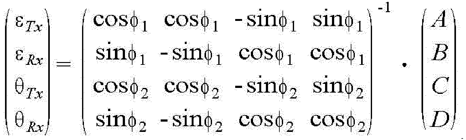 where εTx, θTx, εRx, and θRx denote transmitter gain and phase mismatches and receiver gain and phase mismatches respectively, φ1 denotes phase delay of the first training sequence received through the established first loopback path of a Radio Frequency "RF" unit, and φ2 denotes a phase delay of the second training sequence received through the established second loopback path of the RF unit,wherein A and B are calculated using the first training sequence received through the established first loopback path and the training sequence generated at the transmitter, and C and D are calculated using the second training sequence received through the established second loopback path and the training sequence generated at the transmitter.
Applications Claiming Priority (1)
| Application Number | Priority Date | Filing Date | Title |
|---|---|---|---|
| KR1020140000614A KR101975789B1 (en) | 2014-01-03 | 2014-01-03 | The method and transceiver of i/q mismatch compensation |
Publications (2)
| Publication Number | Publication Date |
|---|---|
| EP2892193A1 EP2892193A1 (en) | 2015-07-08 |
| EP2892193B1 true EP2892193B1 (en) | 2017-03-29 |
Family
ID=52444070
Family Applications (1)
| Application Number | Title | Priority Date | Filing Date |
|---|---|---|---|
| EP14200633.7A Active EP2892193B1 (en) | 2014-01-03 | 2014-12-30 | I/Q-mismatch compensation method and apparatus |
Country Status (3)
| Country | Link |
|---|---|
| US (1) | US9231715B2 (en) |
| EP (1) | EP2892193B1 (en) |
| KR (1) | KR101975789B1 (en) |
Cited By (4)
| Publication number | Priority date | Publication date | Assignee | Title |
|---|---|---|---|---|
| US11601146B2 (en) | 2020-04-15 | 2023-03-07 | Micron Technology, Inc. | Wireless devices and systems including examples of compensating power amplifier noise with neural networks or recurrent neural networks |
| US11695614B2 (en) * | 2020-05-15 | 2023-07-04 | Samsung Electronics Co., Ltd. | Systems, methods and devices for joint calibration of transmit and receive IQ mismatch |
| US12040920B2 (en) | 2020-08-13 | 2024-07-16 | Lodestar Licensing Group Llc | Wireless devices and systems including examples of compensating I/Q imbalance with neural networks or recurrent neural networks |
| TWI865780B (en) * | 2020-05-15 | 2024-12-11 | 南韓商三星電子股份有限公司 | System and method of pre-compensating for transmitter in-phase and quadrature mismatch |
Families Citing this family (16)
| Publication number | Priority date | Publication date | Assignee | Title |
|---|---|---|---|---|
| EP3300267B1 (en) * | 2016-09-21 | 2021-02-24 | Intel IP Corporation | Method for increasing an accuracy of a transceiver loopback calibration and transceiver circuit |
| US10637712B2 (en) * | 2016-12-19 | 2020-04-28 | Mitsubishi Electric Corporation | Transceiver |
| JP2018164183A (en) * | 2017-03-24 | 2018-10-18 | 富士通株式会社 | Communication apparatus and distortion compensation method |
| CN108880704B (en) * | 2017-05-15 | 2020-10-30 | 展讯通信(上海)有限公司 | Calibration method, device, storage medium and terminal for IQ imbalance of transceiver |
| US10805130B2 (en) | 2017-09-12 | 2020-10-13 | Intel IP Corporation | Signal cancellation system and method |
| US11055275B2 (en) | 2018-05-15 | 2021-07-06 | Sap Se | Database revalidation using parallel distance-based groups |
| US10432240B1 (en) | 2018-05-22 | 2019-10-01 | Micron Technology, Inc. | Wireless devices and systems including examples of compensating power amplifier noise |
| KR20190143035A (en) * | 2018-06-19 | 2019-12-30 | 삼성전자주식회사 | Method and apparatus for calibration of an in-phase/quadrature mismatch in wireless communication system |
| US10763905B1 (en) * | 2019-06-07 | 2020-09-01 | Micron Technology, Inc. | Wireless devices and systems including examples of mismatch correction scheme |
| EP3967007B1 (en) * | 2019-07-18 | 2024-08-28 | Samsung Electronics Co., Ltd. | Electronic device including transceiver for calibrating i/q imbalance in millimeter wave communication system and method of operating same |
| TWI717864B (en) * | 2019-10-16 | 2021-02-01 | 國立交通大學 | Baseband system for wireless receiver and baseband signal processing method thereof |
| EP4193468B1 (en) * | 2020-08-07 | 2025-09-24 | Analog Devices International Unlimited Company | Apparatus and methods for radio transceivers |
| KR20220099412A (en) * | 2021-01-06 | 2022-07-13 | 삼성전자주식회사 | Wireless network apparatus and operating method thereof |
| US11476889B2 (en) | 2021-03-03 | 2022-10-18 | Apple Inc. | Wireless circuitry with loopback path all-pass filters |
| US20230421428A1 (en) * | 2022-06-27 | 2023-12-28 | Texas Instruments Incorporated | Decoupling transmitter from loopback path iqmm with phase delay-elimination by rotation |
| US12242459B2 (en) | 2022-10-25 | 2025-03-04 | Sap Se | Fine-grained decision on propagation of revalidation |
Family Cites Families (14)
| Publication number | Priority date | Publication date | Assignee | Title |
|---|---|---|---|---|
| US6084862A (en) * | 1997-09-26 | 2000-07-04 | Telefonaktiebolaget Lm Ericsson | Time dispersion measurement in radio communications systems |
| US8325847B2 (en) * | 2001-09-28 | 2012-12-04 | Intel Corporation | Method and apparatus for efficient storage of training sequences for peak to average power constrained modulation formats |
| US7280588B2 (en) * | 2002-03-21 | 2007-10-09 | Vixs Systems Inc. | Correlation module for use in a radio receiver |
| US7187916B2 (en) * | 2003-02-07 | 2007-03-06 | Broadcom Corporation | Method and system for measuring receiver mixer IQ mismatch |
| US8027376B2 (en) * | 2003-02-07 | 2011-09-27 | Broadcom Corporation | Method and system for measuring IQ path mismatch |
| US7706475B1 (en) * | 2005-04-15 | 2010-04-27 | Marvell International Ltd. | Compensation of I/Q mismatch in a communication system using I/Q modulation |
| US20080002566A1 (en) * | 2006-06-29 | 2008-01-03 | Zhongshan Zhang | Training sequence generating method, a communication system and communication method |
| US7546494B2 (en) * | 2006-08-03 | 2009-06-09 | Avalon Microelectronics Inc. | Skew-correcting apparatus using dual loopback |
| US7822389B2 (en) * | 2006-11-09 | 2010-10-26 | Texas Instruments Incorporated | Methods and apparatus to provide an auxiliary receive path to support transmitter functions |
| US8295845B1 (en) * | 2008-12-04 | 2012-10-23 | Qualcomm Atheros, Inc. | Transceiver I/Q mismatch calibration |
| US8699635B2 (en) * | 2009-11-12 | 2014-04-15 | Cambridge Silicon Radio Limited | Frame boundary detection |
| WO2013011973A1 (en) * | 2011-07-19 | 2013-01-24 | 川崎マイクロエレクトロニクス株式会社 | I/q mismatch compensation method and rf transceiver |
| KR101919779B1 (en) * | 2012-02-16 | 2018-11-19 | 엘지전자 주식회사 | Mobile terminal |
| US9054905B2 (en) * | 2013-01-15 | 2015-06-09 | Samsung Electronics Co., Ltd. | Method and apparatus for timing synchronization at sub-sampled rate for sub-sampled wideband systems |
-
2014
- 2014-01-03 KR KR1020140000614A patent/KR101975789B1/en not_active Expired - Fee Related
- 2014-12-30 EP EP14200633.7A patent/EP2892193B1/en active Active
-
2015
- 2015-01-05 US US14/589,584 patent/US9231715B2/en active Active
Non-Patent Citations (1)
| Title |
|---|
| None * |
Cited By (6)
| Publication number | Priority date | Publication date | Assignee | Title |
|---|---|---|---|---|
| US11601146B2 (en) | 2020-04-15 | 2023-03-07 | Micron Technology, Inc. | Wireless devices and systems including examples of compensating power amplifier noise with neural networks or recurrent neural networks |
| US12199650B2 (en) | 2020-04-15 | 2025-01-14 | Micron Technology, Inc. | Wireless devices and systems including examples of compensating power amplifier noise with neural networks or recurrent neural networks |
| US11695614B2 (en) * | 2020-05-15 | 2023-07-04 | Samsung Electronics Co., Ltd. | Systems, methods and devices for joint calibration of transmit and receive IQ mismatch |
| TWI865780B (en) * | 2020-05-15 | 2024-12-11 | 南韓商三星電子股份有限公司 | System and method of pre-compensating for transmitter in-phase and quadrature mismatch |
| US12224893B2 (en) | 2020-05-15 | 2025-02-11 | Samsung Electronics Co., Ltd. | Systems, methods and devices for joint calibration of transmit and receive IQ mismatch |
| US12040920B2 (en) | 2020-08-13 | 2024-07-16 | Lodestar Licensing Group Llc | Wireless devices and systems including examples of compensating I/Q imbalance with neural networks or recurrent neural networks |
Also Published As
| Publication number | Publication date |
|---|---|
| KR101975789B1 (en) | 2019-05-09 |
| KR20150081050A (en) | 2015-07-13 |
| US9231715B2 (en) | 2016-01-05 |
| EP2892193A1 (en) | 2015-07-08 |
| US20150195050A1 (en) | 2015-07-09 |
Similar Documents
| Publication | Publication Date | Title |
|---|---|---|
| US9231715B2 (en) | I/Q mismatch compensation method and apparatus | |
| US9621337B2 (en) | Adaptive I/O mismatch calibration | |
| US10574428B2 (en) | Self-interference channel estimation system and method | |
| KR101455894B1 (en) | Imbalance compensation for direct conversion communication systems | |
| US8010064B2 (en) | Systems and methods for transmitter calibration | |
| JP6339702B2 (en) | Interference cancellation apparatus and method | |
| CN101651480B (en) | Active antenna, base station, method for updating amplitude and phase, and signal processing method | |
| US6516183B1 (en) | Method and apparatus for disturbance compensation of a direct conversion receiver in a full duplex transceiver | |
| US20170070258A1 (en) | Interference phase estimate system and method | |
| US9712369B2 (en) | Method and apparatus for low-complexity frequency dependent IQ imbalance compensation | |
| US8583064B2 (en) | Receiver for estimating and compensating for in-phase/quadrature mismatch | |
| US11539570B2 (en) | I/Q imbalance compensation | |
| JP5151785B2 (en) | Transmitter and transmitter / receiver | |
| CN104158552A (en) | Zero intermediate frequency transmitter, receiver and related method and system | |
| WO2019243139A1 (en) | Calibration system, antenna system and calibration method | |
| JP7147350B2 (en) | Wireless communication device and received signal correction method | |
| US20250096827A1 (en) | Feedback receiver (fbrx) path and closed loop control for transmitter (tx) interference cancellation | |
| KR20210010417A (en) | Electronic apparatus including transceiver for calibrating i/q imbalance in millimeter wave communication system and thereof operating method | |
| US10142041B2 (en) | Homodyne receiver calibration | |
| US20180083823A1 (en) | Transmission and reception circuit, transceiver, and method of correcting time difference of signal | |
| EP3402098B1 (en) | Transceiver for a wireless communication system, and methods for increasing transceiver loopback calibration accuracy | |
| CN121690423A (en) | Method and system for IQ imbalance calibration of ultra-wideband system, electronic device, computer storage medium and program product | |
| US20180278457A1 (en) | Communication device and distortion compensation method |
Legal Events
| Date | Code | Title | Description |
|---|---|---|---|
| PUAI | Public reference made under article 153(3) epc to a published international application that has entered the european phase |
Free format text: ORIGINAL CODE: 0009012 |
|
| 17P | Request for examination filed |
Effective date: 20141230 |
|
| AK | Designated contracting states |
Kind code of ref document: A1 Designated state(s): AL AT BE BG CH CY CZ DE DK EE ES FI FR GB GR HR HU IE IS IT LI LT LU LV MC MK MT NL NO PL PT RO RS SE SI SK SM TR |
|
| AX | Request for extension of the european patent |
Extension state: BA ME |
|
| R17P | Request for examination filed (corrected) |
Effective date: 20160108 |
|
| RBV | Designated contracting states (corrected) |
Designated state(s): AL AT BE BG CH CY CZ DE DK EE ES FI FR GB GR HR HU IE IS IT LI LT LU LV MC MK MT NL NO PL PT RO RS SE SI SK SM TR |
|
| GRAP | Despatch of communication of intention to grant a patent |
Free format text: ORIGINAL CODE: EPIDOSNIGR1 |
|
| RIC1 | Information provided on ipc code assigned before grant |
Ipc: H04L 27/38 20060101AFI20160929BHEP Ipc: H03D 3/00 20060101ALI20160929BHEP Ipc: H04L 27/36 20060101ALI20160929BHEP |
|
| INTG | Intention to grant announced |
Effective date: 20161014 |
|
| GRAS | Grant fee paid |
Free format text: ORIGINAL CODE: EPIDOSNIGR3 |
|
| GRAA | (expected) grant |
Free format text: ORIGINAL CODE: 0009210 |
|
| AK | Designated contracting states |
Kind code of ref document: B1 Designated state(s): AL AT BE BG CH CY CZ DE DK EE ES FI FR GB GR HR HU IE IS IT LI LT LU LV MC MK MT NL NO PL PT RO RS SE SI SK SM TR |
|
| REG | Reference to a national code |
Ref country code: GB Ref legal event code: FG4D |
|
| REG | Reference to a national code |
Ref country code: CH Ref legal event code: EP |
|
| REG | Reference to a national code |
Ref country code: AT Ref legal event code: REF Ref document number: 880707 Country of ref document: AT Kind code of ref document: T Effective date: 20170415 |
|
| REG | Reference to a national code |
Ref country code: IE Ref legal event code: FG4D |
|
| REG | Reference to a national code |
Ref country code: DE Ref legal event code: R096 Ref document number: 602014008045 Country of ref document: DE |
|
| PG25 | Lapsed in a contracting state [announced via postgrant information from national office to epo] |
Ref country code: NO Free format text: LAPSE BECAUSE OF FAILURE TO SUBMIT A TRANSLATION OF THE DESCRIPTION OR TO PAY THE FEE WITHIN THE PRESCRIBED TIME-LIMIT Effective date: 20170629 Ref country code: GR Free format text: LAPSE BECAUSE OF FAILURE TO SUBMIT A TRANSLATION OF THE DESCRIPTION OR TO PAY THE FEE WITHIN THE PRESCRIBED TIME-LIMIT Effective date: 20170630 Ref country code: HR Free format text: LAPSE BECAUSE OF FAILURE TO SUBMIT A TRANSLATION OF THE DESCRIPTION OR TO PAY THE FEE WITHIN THE PRESCRIBED TIME-LIMIT Effective date: 20170329 Ref country code: LT Free format text: LAPSE BECAUSE OF FAILURE TO SUBMIT A TRANSLATION OF THE DESCRIPTION OR TO PAY THE FEE WITHIN THE PRESCRIBED TIME-LIMIT Effective date: 20170329 Ref country code: FI Free format text: LAPSE BECAUSE OF FAILURE TO SUBMIT A TRANSLATION OF THE DESCRIPTION OR TO PAY THE FEE WITHIN THE PRESCRIBED TIME-LIMIT Effective date: 20170329 |
|
| REG | Reference to a national code |
Ref country code: NL Ref legal event code: MP Effective date: 20170329 |
|
| REG | Reference to a national code |
Ref country code: AT Ref legal event code: MK05 Ref document number: 880707 Country of ref document: AT Kind code of ref document: T Effective date: 20170329 |
|
| PG25 | Lapsed in a contracting state [announced via postgrant information from national office to epo] |
Ref country code: LV Free format text: LAPSE BECAUSE OF FAILURE TO SUBMIT A TRANSLATION OF THE DESCRIPTION OR TO PAY THE FEE WITHIN THE PRESCRIBED TIME-LIMIT Effective date: 20170329 Ref country code: RS Free format text: LAPSE BECAUSE OF FAILURE TO SUBMIT A TRANSLATION OF THE DESCRIPTION OR TO PAY THE FEE WITHIN THE PRESCRIBED TIME-LIMIT Effective date: 20170329 Ref country code: BG Free format text: LAPSE BECAUSE OF FAILURE TO SUBMIT A TRANSLATION OF THE DESCRIPTION OR TO PAY THE FEE WITHIN THE PRESCRIBED TIME-LIMIT Effective date: 20170629 Ref country code: SE Free format text: LAPSE BECAUSE OF FAILURE TO SUBMIT A TRANSLATION OF THE DESCRIPTION OR TO PAY THE FEE WITHIN THE PRESCRIBED TIME-LIMIT Effective date: 20170329 |
|
| PG25 | Lapsed in a contracting state [announced via postgrant information from national office to epo] |
Ref country code: NL Free format text: LAPSE BECAUSE OF FAILURE TO SUBMIT A TRANSLATION OF THE DESCRIPTION OR TO PAY THE FEE WITHIN THE PRESCRIBED TIME-LIMIT Effective date: 20170329 |
|
| PG25 | Lapsed in a contracting state [announced via postgrant information from national office to epo] |
Ref country code: AT Free format text: LAPSE BECAUSE OF FAILURE TO SUBMIT A TRANSLATION OF THE DESCRIPTION OR TO PAY THE FEE WITHIN THE PRESCRIBED TIME-LIMIT Effective date: 20170329 Ref country code: IT Free format text: LAPSE BECAUSE OF FAILURE TO SUBMIT A TRANSLATION OF THE DESCRIPTION OR TO PAY THE FEE WITHIN THE PRESCRIBED TIME-LIMIT Effective date: 20170329 Ref country code: EE Free format text: LAPSE BECAUSE OF FAILURE TO SUBMIT A TRANSLATION OF THE DESCRIPTION OR TO PAY THE FEE WITHIN THE PRESCRIBED TIME-LIMIT Effective date: 20170329 Ref country code: ES Free format text: LAPSE BECAUSE OF FAILURE TO SUBMIT A TRANSLATION OF THE DESCRIPTION OR TO PAY THE FEE WITHIN THE PRESCRIBED TIME-LIMIT Effective date: 20170329 Ref country code: SK Free format text: LAPSE BECAUSE OF FAILURE TO SUBMIT A TRANSLATION OF THE DESCRIPTION OR TO PAY THE FEE WITHIN THE PRESCRIBED TIME-LIMIT Effective date: 20170329 Ref country code: RO Free format text: LAPSE BECAUSE OF FAILURE TO SUBMIT A TRANSLATION OF THE DESCRIPTION OR TO PAY THE FEE WITHIN THE PRESCRIBED TIME-LIMIT Effective date: 20170329 Ref country code: CZ Free format text: LAPSE BECAUSE OF FAILURE TO SUBMIT A TRANSLATION OF THE DESCRIPTION OR TO PAY THE FEE WITHIN THE PRESCRIBED TIME-LIMIT Effective date: 20170329 |
|
| REG | Reference to a national code |
Ref country code: FR Ref legal event code: PLFP Year of fee payment: 4 |
|
| PG25 | Lapsed in a contracting state [announced via postgrant information from national office to epo] |
Ref country code: SM Free format text: LAPSE BECAUSE OF FAILURE TO SUBMIT A TRANSLATION OF THE DESCRIPTION OR TO PAY THE FEE WITHIN THE PRESCRIBED TIME-LIMIT Effective date: 20170329 Ref country code: PL Free format text: LAPSE BECAUSE OF FAILURE TO SUBMIT A TRANSLATION OF THE DESCRIPTION OR TO PAY THE FEE WITHIN THE PRESCRIBED TIME-LIMIT Effective date: 20170329 Ref country code: IS Free format text: LAPSE BECAUSE OF FAILURE TO SUBMIT A TRANSLATION OF THE DESCRIPTION OR TO PAY THE FEE WITHIN THE PRESCRIBED TIME-LIMIT Effective date: 20170729 Ref country code: PT Free format text: LAPSE BECAUSE OF FAILURE TO SUBMIT A TRANSLATION OF THE DESCRIPTION OR TO PAY THE FEE WITHIN THE PRESCRIBED TIME-LIMIT Effective date: 20170731 |
|
| REG | Reference to a national code |
Ref country code: DE Ref legal event code: R097 Ref document number: 602014008045 Country of ref document: DE |
|
| PG25 | Lapsed in a contracting state [announced via postgrant information from national office to epo] |
Ref country code: DK Free format text: LAPSE BECAUSE OF FAILURE TO SUBMIT A TRANSLATION OF THE DESCRIPTION OR TO PAY THE FEE WITHIN THE PRESCRIBED TIME-LIMIT Effective date: 20170329 |
|
| PLBE | No opposition filed within time limit |
Free format text: ORIGINAL CODE: 0009261 |
|
| STAA | Information on the status of an ep patent application or granted ep patent |
Free format text: STATUS: NO OPPOSITION FILED WITHIN TIME LIMIT |
|
| 26N | No opposition filed |
Effective date: 20180103 |
|
| PG25 | Lapsed in a contracting state [announced via postgrant information from national office to epo] |
Ref country code: SI Free format text: LAPSE BECAUSE OF FAILURE TO SUBMIT A TRANSLATION OF THE DESCRIPTION OR TO PAY THE FEE WITHIN THE PRESCRIBED TIME-LIMIT Effective date: 20170329 |
|
| REG | Reference to a national code |
Ref country code: CH Ref legal event code: PL |
|
| PG25 | Lapsed in a contracting state [announced via postgrant information from national office to epo] |
Ref country code: LU Free format text: LAPSE BECAUSE OF NON-PAYMENT OF DUE FEES Effective date: 20171230 Ref country code: MT Free format text: LAPSE BECAUSE OF NON-PAYMENT OF DUE FEES Effective date: 20171230 |
|
| REG | Reference to a national code |
Ref country code: IE Ref legal event code: MM4A |
|
| REG | Reference to a national code |
Ref country code: BE Ref legal event code: MM Effective date: 20171231 |
|
| PG25 | Lapsed in a contracting state [announced via postgrant information from national office to epo] |
Ref country code: IE Free format text: LAPSE BECAUSE OF NON-PAYMENT OF DUE FEES Effective date: 20171230 |
|
| PG25 | Lapsed in a contracting state [announced via postgrant information from national office to epo] |
Ref country code: BE Free format text: LAPSE BECAUSE OF NON-PAYMENT OF DUE FEES Effective date: 20171231 Ref country code: LI Free format text: LAPSE BECAUSE OF NON-PAYMENT OF DUE FEES Effective date: 20171231 Ref country code: CH Free format text: LAPSE BECAUSE OF NON-PAYMENT OF DUE FEES Effective date: 20171231 |
|
| PG25 | Lapsed in a contracting state [announced via postgrant information from national office to epo] |
Ref country code: MC Free format text: LAPSE BECAUSE OF FAILURE TO SUBMIT A TRANSLATION OF THE DESCRIPTION OR TO PAY THE FEE WITHIN THE PRESCRIBED TIME-LIMIT Effective date: 20170329 Ref country code: HU Free format text: LAPSE BECAUSE OF FAILURE TO SUBMIT A TRANSLATION OF THE DESCRIPTION OR TO PAY THE FEE WITHIN THE PRESCRIBED TIME-LIMIT; INVALID AB INITIO Effective date: 20141230 |
|
| PG25 | Lapsed in a contracting state [announced via postgrant information from national office to epo] |
Ref country code: CY Free format text: LAPSE BECAUSE OF FAILURE TO SUBMIT A TRANSLATION OF THE DESCRIPTION OR TO PAY THE FEE WITHIN THE PRESCRIBED TIME-LIMIT Effective date: 20170329 |
|
| PG25 | Lapsed in a contracting state [announced via postgrant information from national office to epo] |
Ref country code: MK Free format text: LAPSE BECAUSE OF FAILURE TO SUBMIT A TRANSLATION OF THE DESCRIPTION OR TO PAY THE FEE WITHIN THE PRESCRIBED TIME-LIMIT Effective date: 20170329 |
|
| PGFP | Annual fee paid to national office [announced via postgrant information from national office to epo] |
Ref country code: FR Payment date: 20191122 Year of fee payment: 6 |
|
| PG25 | Lapsed in a contracting state [announced via postgrant information from national office to epo] |
Ref country code: TR Free format text: LAPSE BECAUSE OF FAILURE TO SUBMIT A TRANSLATION OF THE DESCRIPTION OR TO PAY THE FEE WITHIN THE PRESCRIBED TIME-LIMIT Effective date: 20170329 |
|
| PGFP | Annual fee paid to national office [announced via postgrant information from national office to epo] |
Ref country code: GB Payment date: 20191122 Year of fee payment: 6 |
|
| PG25 | Lapsed in a contracting state [announced via postgrant information from national office to epo] |
Ref country code: AL Free format text: LAPSE BECAUSE OF FAILURE TO SUBMIT A TRANSLATION OF THE DESCRIPTION OR TO PAY THE FEE WITHIN THE PRESCRIBED TIME-LIMIT Effective date: 20170329 |
|
| GBPC | Gb: european patent ceased through non-payment of renewal fee |
Effective date: 20201230 |
|
| PG25 | Lapsed in a contracting state [announced via postgrant information from national office to epo] |
Ref country code: FR Free format text: LAPSE BECAUSE OF NON-PAYMENT OF DUE FEES Effective date: 20201231 |
|
| PG25 | Lapsed in a contracting state [announced via postgrant information from national office to epo] |
Ref country code: GB Free format text: LAPSE BECAUSE OF NON-PAYMENT OF DUE FEES Effective date: 20201230 |
|
| PGFP | Annual fee paid to national office [announced via postgrant information from national office to epo] |
Ref country code: DE Payment date: 20241121 Year of fee payment: 11 |