EP2892132A2 - Commutator of motor and motor having the same - Google Patents
Commutator of motor and motor having the same Download PDFInfo
- Publication number
- EP2892132A2 EP2892132A2 EP14200667.5A EP14200667A EP2892132A2 EP 2892132 A2 EP2892132 A2 EP 2892132A2 EP 14200667 A EP14200667 A EP 14200667A EP 2892132 A2 EP2892132 A2 EP 2892132A2
- Authority
- EP
- European Patent Office
- Prior art keywords
- hooks
- motor
- commutator
- recesses
- bent portions
- Prior art date
- Legal status (The legal status is an assumption and is not a legal conclusion. Google has not performed a legal analysis and makes no representation as to the accuracy of the status listed.)
- Granted
Links
Images



Classifications
-
- H—ELECTRICITY
- H01—ELECTRIC ELEMENTS
- H01R—ELECTRICALLY-CONDUCTIVE CONNECTIONS; STRUCTURAL ASSOCIATIONS OF A PLURALITY OF MUTUALLY-INSULATED ELECTRICAL CONNECTING ELEMENTS; COUPLING DEVICES; CURRENT COLLECTORS
- H01R39/00—Rotary current collectors, distributors or interrupters
- H01R39/02—Details for dynamo electric machines
- H01R39/32—Connections of conductor to commutator segment
-
- A—HUMAN NECESSITIES
- A47—FURNITURE; DOMESTIC ARTICLES OR APPLIANCES; COFFEE MILLS; SPICE MILLS; SUCTION CLEANERS IN GENERAL
- A47F—SPECIAL FURNITURE, FITTINGS, OR ACCESSORIES FOR SHOPS, STOREHOUSES, BARS, RESTAURANTS OR THE LIKE; PAYING COUNTERS
- A47F3/00—Show cases or show cabinets
- A47F3/04—Show cases or show cabinets air-conditioned, refrigerated
- A47F3/0404—Cases or cabinets of the closed type
- A47F3/0426—Details
- A47F3/043—Doors, covers
-
- A—HUMAN NECESSITIES
- A47—FURNITURE; DOMESTIC ARTICLES OR APPLIANCES; COFFEE MILLS; SPICE MILLS; SUCTION CLEANERS IN GENERAL
- A47F—SPECIAL FURNITURE, FITTINGS, OR ACCESSORIES FOR SHOPS, STOREHOUSES, BARS, RESTAURANTS OR THE LIKE; PAYING COUNTERS
- A47F3/00—Show cases or show cabinets
- A47F3/001—Devices for lighting, humidifying, heating, ventilation
-
- A—HUMAN NECESSITIES
- A47—FURNITURE; DOMESTIC ARTICLES OR APPLIANCES; COFFEE MILLS; SPICE MILLS; SUCTION CLEANERS IN GENERAL
- A47F—SPECIAL FURNITURE, FITTINGS, OR ACCESSORIES FOR SHOPS, STOREHOUSES, BARS, RESTAURANTS OR THE LIKE; PAYING COUNTERS
- A47F3/00—Show cases or show cabinets
- A47F3/005—Show cases or show cabinets with glass panels
-
- F—MECHANICAL ENGINEERING; LIGHTING; HEATING; WEAPONS; BLASTING
- F25—REFRIGERATION OR COOLING; COMBINED HEATING AND REFRIGERATION SYSTEMS; HEAT PUMP SYSTEMS; MANUFACTURE OR STORAGE OF ICE; LIQUEFACTION SOLIDIFICATION OF GASES
- F25D—REFRIGERATORS; COLD ROOMS; ICE-BOXES; COOLING OR FREEZING APPARATUS NOT OTHERWISE PROVIDED FOR
- F25D21/00—Defrosting; Preventing frosting; Removing condensed or defrost water
- F25D21/04—Preventing the formation of frost or condensate
-
- F—MECHANICAL ENGINEERING; LIGHTING; HEATING; WEAPONS; BLASTING
- F25—REFRIGERATION OR COOLING; COMBINED HEATING AND REFRIGERATION SYSTEMS; HEAT PUMP SYSTEMS; MANUFACTURE OR STORAGE OF ICE; LIQUEFACTION SOLIDIFICATION OF GASES
- F25D—REFRIGERATORS; COLD ROOMS; ICE-BOXES; COOLING OR FREEZING APPARATUS NOT OTHERWISE PROVIDED FOR
- F25D21/00—Defrosting; Preventing frosting; Removing condensed or defrost water
- F25D21/06—Removing frost
- F25D21/08—Removing frost by electric heating
-
- H—ELECTRICITY
- H02—GENERATION; CONVERSION OR DISTRIBUTION OF ELECTRIC POWER
- H02K—DYNAMO-ELECTRIC MACHINES
- H02K13/00—Structural associations of current collectors with motors or generators, e.g. brush mounting plates or connections to windings; Disposition of current collectors in motors or generators; Arrangements for improving commutation
- H02K13/006—Structural associations of commutators
-
- F—MECHANICAL ENGINEERING; LIGHTING; HEATING; WEAPONS; BLASTING
- F25—REFRIGERATION OR COOLING; COMBINED HEATING AND REFRIGERATION SYSTEMS; HEAT PUMP SYSTEMS; MANUFACTURE OR STORAGE OF ICE; LIQUEFACTION SOLIDIFICATION OF GASES
- F25D—REFRIGERATORS; COLD ROOMS; ICE-BOXES; COOLING OR FREEZING APPARATUS NOT OTHERWISE PROVIDED FOR
- F25D2700/00—Means for sensing or measuring; Sensors therefor
- F25D2700/12—Sensors measuring the inside temperature
-
- F—MECHANICAL ENGINEERING; LIGHTING; HEATING; WEAPONS; BLASTING
- F25—REFRIGERATION OR COOLING; COMBINED HEATING AND REFRIGERATION SYSTEMS; HEAT PUMP SYSTEMS; MANUFACTURE OR STORAGE OF ICE; LIQUEFACTION SOLIDIFICATION OF GASES
- F25D—REFRIGERATORS; COLD ROOMS; ICE-BOXES; COOLING OR FREEZING APPARATUS NOT OTHERWISE PROVIDED FOR
- F25D2700/00—Means for sensing or measuring; Sensors therefor
- F25D2700/14—Sensors measuring the temperature outside the refrigerator or freezer
Definitions
- the present invention relates to a commutator of a motor and a motor including the same, and more particularly, to a commutator of a motor having hooks on which coils are wound and a motor including the same.
- a motor is a device that converts electric energy into rotational energy using the force applied to a conductor in a magnetic field.
- a typical motor is provided with a rotatable shaft and a rotor coupled with the shaft.
- a brush is included, and a commutator to which electric current is supplied through the brush is provided.
- Ends of coils wound on the rotor are fixed to the hooks of the commutator.
- the hooks to which the coils are fixed are fused with the surface of the body of the commutator.
- a clearance may occur between the hook and the surface of the body of the commutator due to the elasticity of the coil. Such a clearance may cause defects in contact between the hook and the commutator when the motor is running.
- the present invention is directed to provide a commutator of a motor having hooks with an increased fixing force and a motor including the same.
- the present invention is directed to provide a commutator of a motor in which stability of a coil on an inner surface of a hook is increased and a motor including the same.
- the present invention is directed to provide a commutator of a motor that improves the performance of the motor through coils with a large diameter fixed thereto and a motor including the same.
- a commutator of motor including a body and hooks configured to form coil-receiving spaces between the body and inner surfaces of the hooks, wherein the hooks include recesses concavely formed on the inner surfaces of the hooks, and coils are seated on the recesses.
- the recesses may be formed in a width direction of the hooks.
- each of the hooks may include a plurality of recesses spaced apart from each other in a height direction of the hooks.
- a size of a first recess formed at a relatively higher portion in the height direction may be larger than a size of a second recess formed at a relatively lower portion.
- the hooks may include end portions configured to come in contact with the body and bent portions configured to connect the body and the end portions.
- the bent portions may protrude outward more than the end portions.
- the bent portions may include first bent portions connected to the body and second bent portions connected to the end portions, and curvatures of the first bent portions and the second bent portions may be different from each other.
- the recesses may include serrations.
- the serrations may be formed in a width direction of the hooks.
- the ratio of the thickness of the hooks to the depth of the recesses may be in the range of 1:0.1 to 1:0.5.
- a commutator of a motor including a body and hooks configured to form coil-receiving spaces between the body and inner surfaces of the hooks, wherein the hooks include end portions coming in contact with the body and a bent portions connecting the body and the end portions, and the bent portions protrudes outward more than the end portions.
- a motor including a stator; a rotor arranged in the stator; a shaft coupled with the rotor; and a commutator including a body arranged on upper end of the rotor and hooks protruding from the body, wherein the hooks include recesses formed on the inner surfaces of the hooks.
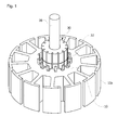
- FIG. 1 illustrates a rotor and a commutator
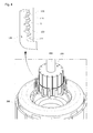
- FIG. 2 illustrates coils combined with hooks of the commutator.
- a plurality of teeth 10a may be formed on a rotor 10 in a radial direction, and coils may be wound on each of the teeth 10a.
- the coils may be combined with hooks 32 formed on the commutator 30.
- the commutator 30 may be installed on the rotor 10 along the circumference of a rotating shaft 20.
- the coils C are located between a body 31 of the commutator 30 and the hooks 32, as shown FIG. 2 .
- Fore ends of the hooks 32 are fused to the surface of the body 31 of the commutator to fix the coils C.
- a clearance may occur between the body 31 of the commutator 30 and the hooks 32.
- the present invention aims to solve this problem fundamentally by mitigating the resisting force of the coils.
- FIG. 3 illustrates a motor according to a preferable embodiment of the present invention
- FIG. 4 illustrates the commutator of the motor shown in FIG. 1 .
- FIG. 3 and FIG. 4 illustrate clearly only major features such that the present invention can be clearly understood conceptually. Therefore, various modifications can be made to the illustrations in the figures, and the scope of the present invention is not limited to the features shown in the figures.
- a motor 1 may include a stator 200 fixed in a housing 40, a rotor 300 arranged in the stator 200, a shaft 400 rotating integrally with the rotor 300, and a commutator 100 arranged on an upper end of the rotor 300.
- the commutator 100 includes a body 110 and hooks 120 protruding along a circumference of the body 110.
- the body 110 is arranged on an upper end of the rotor 300 and has conductive surfaces.
- the hooks 120 may include recesses 130 formed on inner surface 121, on which the coil C is seated.
- a receiving space S on which the coils C are seated is formed between the side of the body 110 and the inner surface 121 of the hook 120.
- the recesses 130 serve to increase the fixing forces between the surface of the body 110 and the hooks 120 by providing receiving spaces for the coils C and thus decreasing the resisting force of the coils C. Also, the recesses 130 serve to lead the coils C to be aligned in the process of fusing the hooks 120 with the body 110.
- the coils C may be end parts of coils wound on the rotor 300.
- the recesses 130 may be concavely formed in a width direction on the inner surfaces 121 of the hooks 120. Also, a plurality of recesses 130 may be formed to be spaced a certain distance apart in a longitudinal direction of the hooks 120.
- serrations 131 may be formed in a width direction.
- the serrations 131 are formed in a concave-convex shape to enlarge the contact area between the coils C and the recesses 130.
- the serrations may be formed with sharp edges to press and indent the coating layer of the coils C.
- FIG. 5 illustrates the recesses shown in FIG. 4 as round recesses.
- the recesses 130 may be grooves as round inner circumferential surfaces. This minimizes the resisting force of the coils C by forming contact areas corresponding to the surfaces of the coils C. In this case, the sizes of the recesses 130 may be appropriately designed considering the diameter of the coils C.
- the body 110 may be formed with a plurality of surface portions 112 attached along an outer circumference surface of a cylindrical core portion 111.
- the surface portions 112 have conductivity, and may be formed integrally with the hooks 120.
- the hooks 120 include end portions 122 coming in contact with the body 110 and bent portions 123 connecting the body 110 and the end portions 122.
- the end portions 122 may come in electrical or physical contact with the body 110 when fused.
- the bent portions 123 may include first bent portions 124 connected to the body 110 and second bent portions 125 connected to the end portions 122.
- the curvatures of the first bent portions 124 and the second bent portions 125 may be different from each other, that is the first bent portions 124 and the second bent portions 125 may not be rotationally symmetric with respect to a center.
- the second bent portions 125 may protrude in a radial direction (perpendicular to an axial direction) more than an outside surface of the end portions 112. With this configuration, the coil-receiving spaces can be formed to be larger to the extent that the second bent portions 125 protrude outward, and thus the resisting force of the coil can be minimized.
- FIG. 6 illustrates recesses of different sizes.
- the recesses 130 may be configured such that the size of the first recess 133 formed at a relatively higher portion in a height direction (direction of a z-axis) is larger than the size of the second recess 132 formed at a lower portion. This minimizes the resisting force of the coils C at the end portions of the hooks 120 fused with the surface of the body 110, and thus increases the combining force between the hooks 120 and the surface of the body 110.
- the present invention is not limited to this, but the second recess 132 may be formed with a larger size than the first recess 133.
- the portion shown with a dotted line may be a protrusion fixed to the body 110.
- FIG. 7 illustrates a thickness of a hook and a size of the recesses.
- the depth t 1 of the recesses 130 and the thickness t 2 of the hook 120 may be formed with a ratio in the range of 0.1:1 to 0.5:1.
- the ratio of the depth t 1 of the recesses 130 and the thickness t 2 of the hook 120 may be 0.2:1.
- the depth t 1 of the recess 130 may refer to the depth of the largest recess 130 located at the uppermost position among the recesses 130.
- the depth t1 of the recess 130 corresponds to the depth capable of ensuring a sufficient coil-receiving space and ensuring a sufficient strength of the hook 120.
- a commutator of a motor includes recesses, in which coils are seated, on the inner surfaces of hooks, and thus an advantageous effect of increasing the fixing forces of the hooks can be obtained.
- a plurality of long recesses are formed in a width direction on the inner surfaces of the hooks, and thus an advantageous effect of aligning and fixing the coils can be obtained.
- serrations are formed in the recesses to increase the contact areas between the coils and the inner surfaces of the hooks, and thus an advantageous effect of further increasing the fixing forces of the hooks can be obtained.
- a size of a recess formed at a relatively higher portion is larger than a size of a recess formed at a lower portion, and thus an advantageous effect of effectively preventing a clearance from occurring at the end of the hook can be obtained.
Landscapes
- Engineering & Computer Science (AREA)
- Physics & Mathematics (AREA)
- Thermal Sciences (AREA)
- Power Engineering (AREA)
- Chemical & Material Sciences (AREA)
- Combustion & Propulsion (AREA)
- Mechanical Engineering (AREA)
- General Engineering & Computer Science (AREA)
- Motor Or Generator Current Collectors (AREA)
- Insulation, Fastening Of Motor, Generator Windings (AREA)
Abstract
Description
- This application claims priority to and the benefit of Korean Patent Application No.
10-2014-0001450, filed on January 06, 2014 - The present invention relates to a commutator of a motor and a motor including the same, and more particularly, to a commutator of a motor having hooks on which coils are wound and a motor including the same.
- A motor is a device that converts electric energy into rotational energy using the force applied to a conductor in a magnetic field. A typical motor is provided with a rotatable shaft and a rotor coupled with the shaft. In the case of a direct current motor, a brush is included, and a commutator to which electric current is supplied through the brush is provided.
- Ends of coils wound on the rotor are fixed to the hooks of the commutator. The hooks to which the coils are fixed are fused with the surface of the body of the commutator. At this time, however, a clearance may occur between the hook and the surface of the body of the commutator due to the elasticity of the coil. Such a clearance may cause defects in contact between the hook and the commutator when the motor is running.
- If the contact between the hook and the commutator is defective, contact resistance will be high and it will interfere with the flow of electric current, thus decreasing the performance of the motor.
- The present invention is directed to provide a commutator of a motor having hooks with an increased fixing force and a motor including the same.
- Also, the present invention is directed to provide a commutator of a motor in which stability of a coil on an inner surface of a hook is increased and a motor including the same.
- Also, the present invention is directed to provide a commutator of a motor that improves the performance of the motor through coils with a large diameter fixed thereto and a motor including the same.
- The objects of the present invention are not limited to the aforementioned objects. Other objects not mentioned above will be clearly understood by those who have ordinary knowledge in the art to which the present invention pertains from the following descriptions.
- According to an aspect of the present invention, there is provided a commutator of motor including a body and hooks configured to form coil-receiving spaces between the body and inner surfaces of the hooks, wherein the hooks include recesses concavely formed on the inner surfaces of the hooks, and coils are seated on the recesses.
- In the commutator of the motor, the recesses may be formed in a width direction of the hooks.
- In the commutator of the motor, each of the hooks may include a plurality of recesses spaced apart from each other in a height direction of the hooks.
- In the commutator of the motor, a size of a first recess formed at a relatively higher portion in the height direction may be larger than a size of a second recess formed at a relatively lower portion.
- In the commutator of the motor, the hooks may include end portions configured to come in contact with the body and bent portions configured to connect the body and the end portions.
- In the commutator of the motor, the bent portions may protrude outward more than the end portions.
- In the commutator of the motor, the bent portions may include first bent portions connected to the body and second bent portions connected to the end portions, and curvatures of the first bent portions and the second bent portions may be different from each other.
- In the commutator of the motor, the recesses may include serrations.
- In the commutator of the motor, the serrations may be formed in a width direction of the hooks.
- In the commutator of the motor, the ratio of the thickness of the hooks to the depth of the recesses may be in the range of 1:0.1 to 1:0.5.
- According to another aspect of the present invention, there is provided a commutator of a motor including a body and hooks configured to form coil-receiving spaces between the body and inner surfaces of the hooks, wherein the hooks include end portions coming in contact with the body and a bent portions connecting the body and the end portions, and the bent portions protrudes outward more than the end portions.
- According to still another aspect of the present invention, there is provided a motor including a stator; a rotor arranged in the stator; a shaft coupled with the rotor; and a commutator including a body arranged on upper end of the rotor and hooks protruding from the body, wherein the hooks include recesses formed on the inner surfaces of the hooks.
-
-
FIG. 1 illustrates a rotor and a commutator. -
FIG. 2 illustrates coils combined with hooks of the commutator. -
FIG. 3 illustrates a motor according to a preferable embodiment of the present invention. -
FIG. 4 illustrates the commutator of the motor shown inFIG. 1 . -
FIG. 5 illustrates the recesses shown inFIG. 4 as round recesses. -
FIG. 6 illustrates recesses of different sizes. -
FIG. 7 illustrates a thickness of a hook and a size of the recesses. - Hereinafter, preferable embodiments of the present invention will be described in detail with reference to the accompanying drawings. The objects, particular advantages and novel features of the present invention will be more apparent from the detailed descriptions associated with the accompanying drawings and the preferable embodiments. The terms and words used in this specification and claims should not be interpreted as being limited to typical dictionary definition, but should be interpreted with meanings and concepts in accord with the technical idea of the present invention based on the principle that an inventor can appropriately define the concepts of terms in order to best explain his or her invention. When describing certain relevant known technology is determined to obscure the point of the present invention, such detailed description will be omitted.
-
FIG. 1 illustrates a rotor and a commutator, andFIG. 2 illustrates coils combined with hooks of the commutator. Referring toFIG. 1 , a plurality ofteeth 10a may be formed on arotor 10 in a radial direction, and coils may be wound on each of theteeth 10a. The coils may be combined withhooks 32 formed on thecommutator 30. - The
commutator 30 may be installed on therotor 10 along the circumference of a rotatingshaft 20. The coils C are located between abody 31 of thecommutator 30 and thehooks 32, as shownFIG. 2 . Fore ends of thehooks 32 are fused to the surface of thebody 31 of the commutator to fix the coils C. However, due to the resisting force of the coils in the process of bending thehooks 32 toward the surface of thebody 31 of thecommutator 30, a clearance may occur between thebody 31 of thecommutator 30 and thehooks 32. The present invention aims to solve this problem fundamentally by mitigating the resisting force of the coils. -
FIG. 3 illustrates a motor according to a preferable embodiment of the present invention, andFIG. 4 illustrates the commutator of the motor shown inFIG. 1 .FIG. 3 andFIG. 4 illustrate clearly only major features such that the present invention can be clearly understood conceptually. Therefore, various modifications can be made to the illustrations in the figures, and the scope of the present invention is not limited to the features shown in the figures. - Referring to
FIG. 3 andFIG.4 , a motor 1 according to a preferable embodiment of the present invention may include astator 200 fixed in ahousing 40, arotor 300 arranged in thestator 200, ashaft 400 rotating integrally with therotor 300, and acommutator 100 arranged on an upper end of therotor 300. - The
commutator 100 includes abody 110 andhooks 120 protruding along a circumference of thebody 110. Thebody 110 is arranged on an upper end of therotor 300 and has conductive surfaces. - The
hooks 120 may includerecesses 130 formed oninner surface 121, on which the coil C is seated. A receiving space S on which the coils C are seated is formed between the side of thebody 110 and theinner surface 121 of thehook 120. - The
recesses 130 serve to increase the fixing forces between the surface of thebody 110 and thehooks 120 by providing receiving spaces for the coils C and thus decreasing the resisting force of the coils C. Also, therecesses 130 serve to lead the coils C to be aligned in the process of fusing thehooks 120 with thebody 110. The coils C may be end parts of coils wound on therotor 300. - In an embodiment, the
recesses 130 may be concavely formed in a width direction on theinner surfaces 121 of thehooks 120. Also, a plurality ofrecesses 130 may be formed to be spaced a certain distance apart in a longitudinal direction of thehooks 120. - In each of the
recesses 130,serrations 131 may be formed in a width direction. In an embodiment, theserrations 131 are formed in a concave-convex shape to enlarge the contact area between the coils C and therecesses 130. Particularly, the serrations may be formed with sharp edges to press and indent the coating layer of the coils C. -
FIG. 5 illustrates the recesses shown inFIG. 4 as round recesses. - As shown in
FIG. 5 , therecesses 130 may be grooves as round inner circumferential surfaces. This minimizes the resisting force of the coils C by forming contact areas corresponding to the surfaces of the coils C. In this case, the sizes of therecesses 130 may be appropriately designed considering the diameter of the coils C. - The
body 110 may be formed with a plurality ofsurface portions 112 attached along an outer circumference surface of acylindrical core portion 111. Thesurface portions 112 have conductivity, and may be formed integrally with thehooks 120. - The
hooks 120 includeend portions 122 coming in contact with thebody 110 andbent portions 123 connecting thebody 110 and theend portions 122. Theend portions 122 may come in electrical or physical contact with thebody 110 when fused. Thebent portions 123 may include firstbent portions 124 connected to thebody 110 and secondbent portions 125 connected to theend portions 122. - The curvatures of the first
bent portions 124 and the secondbent portions 125 may be different from each other, that is the firstbent portions 124 and the secondbent portions 125 may not be rotationally symmetric with respect to a center. The secondbent portions 125 may protrude in a radial direction (perpendicular to an axial direction) more than an outside surface of theend portions 112. With this configuration, the coil-receiving spaces can be formed to be larger to the extent that the secondbent portions 125 protrude outward, and thus the resisting force of the coil can be minimized. -
FIG. 6 illustrates recesses of different sizes. - As shown in
FIG. 6 , therecesses 130 may be configured such that the size of thefirst recess 133 formed at a relatively higher portion in a height direction (direction of a z-axis) is larger than the size of thesecond recess 132 formed at a lower portion. This minimizes the resisting force of the coils C at the end portions of thehooks 120 fused with the surface of thebody 110, and thus increases the combining force between thehooks 120 and the surface of thebody 110. However, the present invention is not limited to this, but thesecond recess 132 may be formed with a larger size than thefirst recess 133. - With these
recesses 130, it is possible not only to increase the combining capability between thebody 110 and thehooks 120, but also to use the coils C having a large diameter, and thus the performance of the motor can be enhanced. InFIG. 6 , the portion shown with a dotted line may be a protrusion fixed to thebody 110. -
FIG. 7 illustrates a thickness of a hook and a size of the recesses. - Referring to
FIG. 7 , the depth t1 of therecesses 130 and the thickness t2 of thehook 120 may be formed with a ratio in the range of 0.1:1 to 0.5:1. The ratio of the depth t1 of therecesses 130 and the thickness t2 of thehook 120 may be 0.2:1. Here, the depth t1 of therecess 130 may refer to the depth of thelargest recess 130 located at the uppermost position among therecesses 130. The depth t1 of therecess 130 corresponds to the depth capable of ensuring a sufficient coil-receiving space and ensuring a sufficient strength of thehook 120. - According to an embodiment of the present invention, a commutator of a motor includes recesses, in which coils are seated, on the inner surfaces of hooks, and thus an advantageous effect of increasing the fixing forces of the hooks can be obtained.
- Further, according to an embodiment of the present invention, a plurality of long recesses are formed in a width direction on the inner surfaces of the hooks, and thus an advantageous effect of aligning and fixing the coils can be obtained.
- Further, according to an embodiment of the present invention, serrations are formed in the recesses to increase the contact areas between the coils and the inner surfaces of the hooks, and thus an advantageous effect of further increasing the fixing forces of the hooks can be obtained.
- Further, according to an embodiment of the present invention, a size of a recess formed at a relatively higher portion is larger than a size of a recess formed at a lower portion, and thus an advantageous effect of effectively preventing a clearance from occurring at the end of the hook can be obtained.
- The above descriptions merely explain the technical idea of the present invention exemplarily, and it will be apparent to those skilled in the art that various changes, modifications and substitutions can be made to the above-described exemplary embodiments of the present invention without departing from the spirit or scope of the invention. Therefore, the disclosed embodiments and the appended drawings are not provided to limit the technical idea of the present invention but to explain the technical idea of the present invention. Accordingly, the present invention is not limited to these embodiments or drawings. The scope of the present invention should be determined based on the scope of the appended claims, and all the technical ideas within the scope of the claims and their equivalents are to be included within the scope of the present invention.
Claims (15)
- A commutator of a motor comprising a body(110) and hooks(120) forming coil-receiving spaces(S) between the body(110) and inner surfaces(121) of the hooks(120),
wherein the hooks(120) comprise recesses(130) concavely formed on the inner surfaces(121) of the hooks(120), and coils(C) are seated on the recesses(130). - The commutator of the motor of claim 1, wherein the recesses(130) are formed in width directions of the hooks(120).
- The commutator of the motor of claim 2, wherein each of the hooks(120) comprises a plurality of the recesses(130) spaced in a height direction of the hooks(120).
- The commutator of the motor of claim 3, wherein a size of a first recess(133) formed at a relatively higher portion in the height direction is larger than a size of a second recess(132) arranged at a lower portion.
- The commutator of the motor of claim 1, wherein the hooks(120) comprise end portions(122) coming in contact with the body(110) and bent portions(123) connecting the body(110) and the end portions(122).
- The commutator of the motor of claim 5, wherein the bent portions(123) protrude outward more than the end portions(122).
- The commutator of the motor of claim 5, wherein the bent portions(123) comprise first bent portions(124) connected to the body(110) and second bent portions(125) connected to the end portions(122), and curvatures of the first bent portions(124) and the second bent portions(125) are different from each other.
- The commutator of the motor of claim 1, wherein the recesses(130) comprise serrations(131).
- The commutator of the motor of claim 8, wherein the serrations(131) are formed in a width direction of the hooks(120).
- The commutator of the motor of claim 1, wherein a ratio of a thickness of the hooks(120) to a depth of the recesses(130) is in the range of 1:0.1 to 1:0.5.
- A commutator of a motor comprising a body(110) and hooks(120) forming coil-receiving spaces(S) between the body(110) and inner surfaces(121) of the hooks(120), wherein the hooks(120) comprise end portions(122) being in contact with the body(110) and bent portions(123) connecting the body(110) and the end portions(122), and the bent portions(123) protrude outward more than the end portions(122).
- A motor comprising:a stator(200);a rotor(300) arranged in the stator(200);a shaft(20) coupled with the rotor(300); anda commutator comprising a body(110) arranged on an upper end of the rotor(300) and hooks(120) protruding from the body(110),wherein the hooks(120) comprise recesses(130) formed on inner surfaces(121) of the hooks(120).
- The motor of claim 12, wherein the recesses(130) are formed in width directions of the hooks(120).
- The motor of claim 12, wherein each of the hooks(120) comprises a plurality of recesses(130) spaced along a height direction of the hooks(120).
- The motor of claim 14, wherein a size of a first recess(133) formed at a relatively higher portion in the height direction is larger than a size of a second recess(132) arranged at a lower portion.
Applications Claiming Priority (1)
| Application Number | Priority Date | Filing Date | Title |
|---|---|---|---|
| KR1020140001450A KR102233276B1 (en) | 2014-01-06 | 2014-01-06 | Commutator of motor and Motor having the same |
Publications (3)
| Publication Number | Publication Date |
|---|---|
| EP2892132A2 true EP2892132A2 (en) | 2015-07-08 |
| EP2892132A3 EP2892132A3 (en) | 2016-07-13 |
| EP2892132B1 EP2892132B1 (en) | 2020-02-26 |
Family
ID=52130172
Family Applications (1)
| Application Number | Title | Priority Date | Filing Date |
|---|---|---|---|
| EP14200667.5A Active EP2892132B1 (en) | 2014-01-06 | 2014-12-30 | Commutator of motor and motor having the same |
Country Status (4)
| Country | Link |
|---|---|
| US (1) | US9837775B2 (en) |
| EP (1) | EP2892132B1 (en) |
| KR (1) | KR102233276B1 (en) |
| CN (1) | CN104767328B (en) |
Cited By (1)
| Publication number | Priority date | Publication date | Assignee | Title |
|---|---|---|---|---|
| EP3525326A1 (en) * | 2018-02-07 | 2019-08-14 | Askoll Holding S.r.l. a socio unico | Improved commutator, rotor comprising said improved commutator, electric motor comprising said rotor and method for manufacturing said rotor |
Families Citing this family (5)
| Publication number | Priority date | Publication date | Assignee | Title |
|---|---|---|---|---|
| KR101786671B1 (en) * | 2015-12-02 | 2017-10-18 | 현대자동차 주식회사 | Rotor structure of wrsm motor |
| JP6301899B2 (en) * | 2015-12-02 | 2018-03-28 | ミネベアミツミ株式会社 | Motor stator and inner rotor type motor provided with the stator |
| KR102701654B1 (en) * | 2016-06-09 | 2024-09-03 | 엘지이노텍 주식회사 | Ground terminal, Cover assembly and vehicle having the same |
| JP6695240B2 (en) * | 2016-08-31 | 2020-05-20 | 株式会社ミツバ | Commutator |
| DE102023127577A1 (en) * | 2023-10-10 | 2025-04-10 | Audi Aktiengesellschaft | Contacting hook and contacting arrangement for providing an electrical contact to a winding arrangement of an electrical machine and method for producing a contacting arrangement |
Family Cites Families (16)
| Publication number | Priority date | Publication date | Assignee | Title |
|---|---|---|---|---|
| SE381137B (en) * | 1973-04-06 | 1975-11-24 | Electrolux Ab | COMMUTER FOR ELECTRICAL MACHINES AND THE WAY TO MANUFACTURE SUCH A COMMUTER |
| JPS59107574U (en) * | 1982-12-29 | 1984-07-19 | マブチモ−タ−株式会社 | Commutator device for small motors |
| DE3328527A1 (en) * | 1983-08-06 | 1985-02-21 | Robert Bosch Gmbh, 7000 Stuttgart | CONNECTION BETWEEN ANCHOR WINDING END AND ASSIGNED SEGMENTS OF A COMMUTATOR |
| GB2198890B (en) * | 1986-12-11 | 1992-01-08 | Johnson Electric Ind Mfg | A commutator for an electric motor |
| DE4026025B4 (en) * | 1990-08-17 | 2004-02-12 | Itt Automotive Europe Gmbh | Anchor for an electric motor |
| JP3343434B2 (en) * | 1994-02-01 | 2002-11-11 | アスモ株式会社 | Commutator |
| US5547122A (en) * | 1995-03-07 | 1996-08-20 | United Technologies Motor Systems, Inc. | Joints in bonding of electrical wires |
| JP3256688B2 (en) * | 1999-09-30 | 2002-02-12 | 三菱電機株式会社 | Rectifier |
| FR2801740A1 (en) * | 1999-11-29 | 2001-06-01 | Valeo Systemes Dessuyage | Armature commutator for electric motor includes contact strips with hooked ends for retaining ends of winding wires |
| KR100424873B1 (en) * | 2000-05-12 | 2004-03-27 | 미쓰비시덴키 가부시키가이샤 | Commutating device |
| JP3908588B2 (en) * | 2001-06-06 | 2007-04-25 | マブチモーター株式会社 | Small motor rotor and method of manufacturing the same |
| JP4975307B2 (en) * | 2005-12-12 | 2012-07-11 | アスモ株式会社 | Manufacturing method of armature, joining method of winding and terminal |
| DE102006046666A1 (en) * | 2006-09-29 | 2008-04-03 | Robert Bosch Gmbh | Flat commutator for e.g. electrical machine, has bar widened in circumferential direction when axially viewed from brush running surface in direction of connection hook and/or viewed from connection hook in direction of running surface |
| DE102009024507A1 (en) * | 2009-06-08 | 2010-12-09 | Brose Fahrzeugteile GmbH & Co. Kommanditgesellschaft, Würzburg | Rotor for an electric motor |
| KR20120006354A (en) | 2010-07-12 | 2012-01-18 | 엘지이노텍 주식회사 | Vibration motor |
| CN202602049U (en) * | 2012-05-17 | 2012-12-12 | 深圳市凯中精密技术股份有限公司 | Improved hook-piece-type commutator |
-
2014
- 2014-01-06 KR KR1020140001450A patent/KR102233276B1/en active Active
- 2014-12-30 EP EP14200667.5A patent/EP2892132B1/en active Active
-
2015
- 2015-01-06 CN CN201510005330.4A patent/CN104767328B/en active Active
- 2015-01-06 US US14/590,131 patent/US9837775B2/en not_active Expired - Fee Related
Non-Patent Citations (1)
| Title |
|---|
| None |
Cited By (1)
| Publication number | Priority date | Publication date | Assignee | Title |
|---|---|---|---|---|
| EP3525326A1 (en) * | 2018-02-07 | 2019-08-14 | Askoll Holding S.r.l. a socio unico | Improved commutator, rotor comprising said improved commutator, electric motor comprising said rotor and method for manufacturing said rotor |
Also Published As
| Publication number | Publication date |
|---|---|
| KR20150081702A (en) | 2015-07-15 |
| CN104767328B (en) | 2017-08-22 |
| EP2892132B1 (en) | 2020-02-26 |
| EP2892132A3 (en) | 2016-07-13 |
| KR102233276B1 (en) | 2021-03-29 |
| CN104767328A (en) | 2015-07-08 |
| US20150194779A1 (en) | 2015-07-09 |
| US9837775B2 (en) | 2017-12-05 |
Similar Documents
| Publication | Publication Date | Title |
|---|---|---|
| EP2892132B1 (en) | Commutator of motor and motor having the same | |
| US11018551B2 (en) | Motor | |
| CN110798001B (en) | Electric motor | |
| JP6885333B2 (en) | Stator and motor | |
| US20140306562A1 (en) | Motor connecting member and motor device | |
| KR102497011B1 (en) | Stator structure of hairpin winding motor | |
| JP6436381B2 (en) | Motor armature and motor | |
| JP4770752B2 (en) | Contact device | |
| CN105743258B (en) | Stator assembly, motor having the same, and method of manufacturing the same | |
| JP2015226466A (en) | Electric motor | |
| US10128718B2 (en) | Stator, brushless motor, and stator manufacturing method | |
| JP2019515633A (en) | motor | |
| US10566867B2 (en) | Stator and method of manufacturing stator | |
| CN107431400B (en) | Rotary motor | |
| CN103748770B (en) | Rectifier, the manufacture method of rectifier and electro-motor | |
| CN111684686A (en) | motor | |
| JP2016111844A (en) | Stator for rotary electric machine | |
| KR102305652B1 (en) | Motor | |
| JP2015154497A (en) | Rotating electrical machine stator | |
| US11056958B2 (en) | Rotor and motor having the same | |
| CN106257807B (en) | energy transmission equipment | |
| KR102143055B1 (en) | Motor | |
| JP5692271B2 (en) | Rotor and rotating electric machine equipped with the same | |
| JP2013093944A (en) | Dc motor | |
| JP2017085809A (en) | Rotating electric machine stator |
Legal Events
| Date | Code | Title | Description |
|---|---|---|---|
| PUAI | Public reference made under article 153(3) epc to a published international application that has entered the european phase |
Free format text: ORIGINAL CODE: 0009012 |
|
| 17P | Request for examination filed |
Effective date: 20150116 |
|
| AK | Designated contracting states |
Kind code of ref document: A2 Designated state(s): AL AT BE BG CH CY CZ DE DK EE ES FI FR GB GR HR HU IE IS IT LI LT LU LV MC MK MT NL NO PL PT RO RS SE SI SK SM TR |
|
| AX | Request for extension of the european patent |
Extension state: BA ME |
|
| PUAL | Search report despatched |
Free format text: ORIGINAL CODE: 0009013 |
|
| AK | Designated contracting states |
Kind code of ref document: A3 Designated state(s): AL AT BE BG CH CY CZ DE DK EE ES FI FR GB GR HR HU IE IS IT LI LT LU LV MC MK MT NL NO PL PT RO RS SE SI SK SM TR |
|
| AX | Request for extension of the european patent |
Extension state: BA ME |
|
| RIC1 | Information provided on ipc code assigned before grant |
Ipc: H02K 13/00 20060101AFI20160606BHEP Ipc: H01R 39/32 20060101ALI20160606BHEP |
|
| RBV | Designated contracting states (corrected) |
Designated state(s): AL AT BE BG CH CY CZ DE DK EE ES FI FR GB GR HR HU IE IS IT LI LT LU LV MC MK MT NL NO PL PT RO RS SE SI SK SM TR |
|
| RAP1 | Party data changed (applicant data changed or rights of an application transferred) |
Owner name: LG INNOTEK CO., LTD. |
|
| RIC1 | Information provided on ipc code assigned before grant |
Ipc: H01R 39/32 20060101ALI20190916BHEP Ipc: H02K 13/00 20060101AFI20190916BHEP |
|
| GRAP | Despatch of communication of intention to grant a patent |
Free format text: ORIGINAL CODE: EPIDOSNIGR1 |
|
| STAA | Information on the status of an ep patent application or granted ep patent |
Free format text: STATUS: GRANT OF PATENT IS INTENDED |
|
| INTG | Intention to grant announced |
Effective date: 20191126 |
|
| GRAS | Grant fee paid |
Free format text: ORIGINAL CODE: EPIDOSNIGR3 |
|
| GRAA | (expected) grant |
Free format text: ORIGINAL CODE: 0009210 |
|
| STAA | Information on the status of an ep patent application or granted ep patent |
Free format text: STATUS: THE PATENT HAS BEEN GRANTED |
|
| AK | Designated contracting states |
Kind code of ref document: B1 Designated state(s): AL AT BE BG CH CY CZ DE DK EE ES FI FR GB GR HR HU IE IS IT LI LT LU LV MC MK MT NL NO PL PT RO RS SE SI SK SM TR |
|
| REG | Reference to a national code |
Ref country code: GB Ref legal event code: FG4D |
|
| REG | Reference to a national code |
Ref country code: CH Ref legal event code: EP |
|
| REG | Reference to a national code |
Ref country code: AT Ref legal event code: REF Ref document number: 1238851 Country of ref document: AT Kind code of ref document: T Effective date: 20200315 |
|
| REG | Reference to a national code |
Ref country code: IE Ref legal event code: FG4D |
|
| REG | Reference to a national code |
Ref country code: DE Ref legal event code: R096 Ref document number: 602014061457 Country of ref document: DE |
|
| PG25 | Lapsed in a contracting state [announced via postgrant information from national office to epo] |
Ref country code: NO Free format text: LAPSE BECAUSE OF FAILURE TO SUBMIT A TRANSLATION OF THE DESCRIPTION OR TO PAY THE FEE WITHIN THE PRESCRIBED TIME-LIMIT Effective date: 20200526 Ref country code: RS Free format text: LAPSE BECAUSE OF FAILURE TO SUBMIT A TRANSLATION OF THE DESCRIPTION OR TO PAY THE FEE WITHIN THE PRESCRIBED TIME-LIMIT Effective date: 20200226 Ref country code: FI Free format text: LAPSE BECAUSE OF FAILURE TO SUBMIT A TRANSLATION OF THE DESCRIPTION OR TO PAY THE FEE WITHIN THE PRESCRIBED TIME-LIMIT Effective date: 20200226 |
|
| REG | Reference to a national code |
Ref country code: NL Ref legal event code: MP Effective date: 20200226 |
|
| REG | Reference to a national code |
Ref country code: LT Ref legal event code: MG4D |
|
| PG25 | Lapsed in a contracting state [announced via postgrant information from national office to epo] |
Ref country code: LV Free format text: LAPSE BECAUSE OF FAILURE TO SUBMIT A TRANSLATION OF THE DESCRIPTION OR TO PAY THE FEE WITHIN THE PRESCRIBED TIME-LIMIT Effective date: 20200226 Ref country code: IS Free format text: LAPSE BECAUSE OF FAILURE TO SUBMIT A TRANSLATION OF THE DESCRIPTION OR TO PAY THE FEE WITHIN THE PRESCRIBED TIME-LIMIT Effective date: 20200626 Ref country code: SE Free format text: LAPSE BECAUSE OF FAILURE TO SUBMIT A TRANSLATION OF THE DESCRIPTION OR TO PAY THE FEE WITHIN THE PRESCRIBED TIME-LIMIT Effective date: 20200226 Ref country code: HR Free format text: LAPSE BECAUSE OF FAILURE TO SUBMIT A TRANSLATION OF THE DESCRIPTION OR TO PAY THE FEE WITHIN THE PRESCRIBED TIME-LIMIT Effective date: 20200226 Ref country code: BG Free format text: LAPSE BECAUSE OF FAILURE TO SUBMIT A TRANSLATION OF THE DESCRIPTION OR TO PAY THE FEE WITHIN THE PRESCRIBED TIME-LIMIT Effective date: 20200526 Ref country code: GR Free format text: LAPSE BECAUSE OF FAILURE TO SUBMIT A TRANSLATION OF THE DESCRIPTION OR TO PAY THE FEE WITHIN THE PRESCRIBED TIME-LIMIT Effective date: 20200527 |
|
| PG25 | Lapsed in a contracting state [announced via postgrant information from national office to epo] |
Ref country code: NL Free format text: LAPSE BECAUSE OF FAILURE TO SUBMIT A TRANSLATION OF THE DESCRIPTION OR TO PAY THE FEE WITHIN THE PRESCRIBED TIME-LIMIT Effective date: 20200226 |
|
| PG25 | Lapsed in a contracting state [announced via postgrant information from national office to epo] |
Ref country code: SK Free format text: LAPSE BECAUSE OF FAILURE TO SUBMIT A TRANSLATION OF THE DESCRIPTION OR TO PAY THE FEE WITHIN THE PRESCRIBED TIME-LIMIT Effective date: 20200226 Ref country code: SM Free format text: LAPSE BECAUSE OF FAILURE TO SUBMIT A TRANSLATION OF THE DESCRIPTION OR TO PAY THE FEE WITHIN THE PRESCRIBED TIME-LIMIT Effective date: 20200226 Ref country code: EE Free format text: LAPSE BECAUSE OF FAILURE TO SUBMIT A TRANSLATION OF THE DESCRIPTION OR TO PAY THE FEE WITHIN THE PRESCRIBED TIME-LIMIT Effective date: 20200226 Ref country code: DK Free format text: LAPSE BECAUSE OF FAILURE TO SUBMIT A TRANSLATION OF THE DESCRIPTION OR TO PAY THE FEE WITHIN THE PRESCRIBED TIME-LIMIT Effective date: 20200226 Ref country code: PT Free format text: LAPSE BECAUSE OF FAILURE TO SUBMIT A TRANSLATION OF THE DESCRIPTION OR TO PAY THE FEE WITHIN THE PRESCRIBED TIME-LIMIT Effective date: 20200719 Ref country code: LT Free format text: LAPSE BECAUSE OF FAILURE TO SUBMIT A TRANSLATION OF THE DESCRIPTION OR TO PAY THE FEE WITHIN THE PRESCRIBED TIME-LIMIT Effective date: 20200226 Ref country code: ES Free format text: LAPSE BECAUSE OF FAILURE TO SUBMIT A TRANSLATION OF THE DESCRIPTION OR TO PAY THE FEE WITHIN THE PRESCRIBED TIME-LIMIT Effective date: 20200226 Ref country code: CZ Free format text: LAPSE BECAUSE OF FAILURE TO SUBMIT A TRANSLATION OF THE DESCRIPTION OR TO PAY THE FEE WITHIN THE PRESCRIBED TIME-LIMIT Effective date: 20200226 Ref country code: RO Free format text: LAPSE BECAUSE OF FAILURE TO SUBMIT A TRANSLATION OF THE DESCRIPTION OR TO PAY THE FEE WITHIN THE PRESCRIBED TIME-LIMIT Effective date: 20200226 |
|
| REG | Reference to a national code |
Ref country code: AT Ref legal event code: MK05 Ref document number: 1238851 Country of ref document: AT Kind code of ref document: T Effective date: 20200226 |
|
| REG | Reference to a national code |
Ref country code: DE Ref legal event code: R097 Ref document number: 602014061457 Country of ref document: DE |
|
| PLBE | No opposition filed within time limit |
Free format text: ORIGINAL CODE: 0009261 |
|
| STAA | Information on the status of an ep patent application or granted ep patent |
Free format text: STATUS: NO OPPOSITION FILED WITHIN TIME LIMIT |
|
| PG25 | Lapsed in a contracting state [announced via postgrant information from national office to epo] |
Ref country code: AT Free format text: LAPSE BECAUSE OF FAILURE TO SUBMIT A TRANSLATION OF THE DESCRIPTION OR TO PAY THE FEE WITHIN THE PRESCRIBED TIME-LIMIT Effective date: 20200226 Ref country code: IT Free format text: LAPSE BECAUSE OF FAILURE TO SUBMIT A TRANSLATION OF THE DESCRIPTION OR TO PAY THE FEE WITHIN THE PRESCRIBED TIME-LIMIT Effective date: 20200226 |
|
| 26N | No opposition filed |
Effective date: 20201127 |
|
| PG25 | Lapsed in a contracting state [announced via postgrant information from national office to epo] |
Ref country code: SI Free format text: LAPSE BECAUSE OF FAILURE TO SUBMIT A TRANSLATION OF THE DESCRIPTION OR TO PAY THE FEE WITHIN THE PRESCRIBED TIME-LIMIT Effective date: 20200226 Ref country code: PL Free format text: LAPSE BECAUSE OF FAILURE TO SUBMIT A TRANSLATION OF THE DESCRIPTION OR TO PAY THE FEE WITHIN THE PRESCRIBED TIME-LIMIT Effective date: 20200226 |
|
| REG | Reference to a national code |
Ref country code: CH Ref legal event code: PL |
|
| PG25 | Lapsed in a contracting state [announced via postgrant information from national office to epo] |
Ref country code: MC Free format text: LAPSE BECAUSE OF FAILURE TO SUBMIT A TRANSLATION OF THE DESCRIPTION OR TO PAY THE FEE WITHIN THE PRESCRIBED TIME-LIMIT Effective date: 20200226 |
|
| REG | Reference to a national code |
Ref country code: BE Ref legal event code: MM Effective date: 20201231 |
|
| PG25 | Lapsed in a contracting state [announced via postgrant information from national office to epo] |
Ref country code: IE Free format text: LAPSE BECAUSE OF NON-PAYMENT OF DUE FEES Effective date: 20201230 Ref country code: LU Free format text: LAPSE BECAUSE OF NON-PAYMENT OF DUE FEES Effective date: 20201230 |
|
| PG25 | Lapsed in a contracting state [announced via postgrant information from national office to epo] |
Ref country code: LI Free format text: LAPSE BECAUSE OF NON-PAYMENT OF DUE FEES Effective date: 20201231 Ref country code: CH Free format text: LAPSE BECAUSE OF NON-PAYMENT OF DUE FEES Effective date: 20201231 |
|
| PG25 | Lapsed in a contracting state [announced via postgrant information from national office to epo] |
Ref country code: TR Free format text: LAPSE BECAUSE OF FAILURE TO SUBMIT A TRANSLATION OF THE DESCRIPTION OR TO PAY THE FEE WITHIN THE PRESCRIBED TIME-LIMIT Effective date: 20200226 Ref country code: MT Free format text: LAPSE BECAUSE OF FAILURE TO SUBMIT A TRANSLATION OF THE DESCRIPTION OR TO PAY THE FEE WITHIN THE PRESCRIBED TIME-LIMIT Effective date: 20200226 Ref country code: CY Free format text: LAPSE BECAUSE OF FAILURE TO SUBMIT A TRANSLATION OF THE DESCRIPTION OR TO PAY THE FEE WITHIN THE PRESCRIBED TIME-LIMIT Effective date: 20200226 |
|
| PG25 | Lapsed in a contracting state [announced via postgrant information from national office to epo] |
Ref country code: MK Free format text: LAPSE BECAUSE OF FAILURE TO SUBMIT A TRANSLATION OF THE DESCRIPTION OR TO PAY THE FEE WITHIN THE PRESCRIBED TIME-LIMIT Effective date: 20200226 Ref country code: AL Free format text: LAPSE BECAUSE OF FAILURE TO SUBMIT A TRANSLATION OF THE DESCRIPTION OR TO PAY THE FEE WITHIN THE PRESCRIBED TIME-LIMIT Effective date: 20200226 |
|
| PG25 | Lapsed in a contracting state [announced via postgrant information from national office to epo] |
Ref country code: BE Free format text: LAPSE BECAUSE OF NON-PAYMENT OF DUE FEES Effective date: 20201231 |
|
| PGFP | Annual fee paid to national office [announced via postgrant information from national office to epo] |
Ref country code: DE Payment date: 20241121 Year of fee payment: 11 |
|
| PGFP | Annual fee paid to national office [announced via postgrant information from national office to epo] |
Ref country code: GB Payment date: 20241121 Year of fee payment: 11 |
|
| PGFP | Annual fee paid to national office [announced via postgrant information from national office to epo] |
Ref country code: FR Payment date: 20241121 Year of fee payment: 11 |