EP2892125A2 - Battery charging device and battery charging method - Google Patents
Battery charging device and battery charging method Download PDFInfo
- Publication number
- EP2892125A2 EP2892125A2 EP14195528.6A EP14195528A EP2892125A2 EP 2892125 A2 EP2892125 A2 EP 2892125A2 EP 14195528 A EP14195528 A EP 14195528A EP 2892125 A2 EP2892125 A2 EP 2892125A2
- Authority
- EP
- European Patent Office
- Prior art keywords
- battery
- battery module
- open circuit
- charging
- circuit voltage
- Prior art date
- Legal status (The legal status is an assumption and is not a legal conclusion. Google has not performed a legal analysis and makes no representation as to the accuracy of the status listed.)
- Withdrawn
Links
Images



Classifications
-
- H—ELECTRICITY
- H02—GENERATION; CONVERSION OR DISTRIBUTION OF ELECTRIC POWER
- H02J—ELECTRIC POWER NETWORKS; CIRCUIT ARRANGEMENTS OR SYSTEMS FOR SUPPLYING OR DISTRIBUTING ELECTRIC POWER; SYSTEMS FOR STORING ELECTRIC ENERGY
- H02J7/00—Circuit arrangements for charging or discharging batteries or for supplying loads from batteries
- H02J7/60—Circuit arrangements for charging or discharging batteries or for supplying loads from batteries including safety or protection arrangements
-
- H—ELECTRICITY
- H02—GENERATION; CONVERSION OR DISTRIBUTION OF ELECTRIC POWER
- H02J—ELECTRIC POWER NETWORKS; CIRCUIT ARRANGEMENTS OR SYSTEMS FOR SUPPLYING OR DISTRIBUTING ELECTRIC POWER; SYSTEMS FOR STORING ELECTRIC ENERGY
- H02J7/00—Circuit arrangements for charging or discharging batteries or for supplying loads from batteries
- H02J7/90—Regulation of charging or discharging current or voltage
-
- H—ELECTRICITY
- H02—GENERATION; CONVERSION OR DISTRIBUTION OF ELECTRIC POWER
- H02J—ELECTRIC POWER NETWORKS; CIRCUIT ARRANGEMENTS OR SYSTEMS FOR SUPPLYING OR DISTRIBUTING ELECTRIC POWER; SYSTEMS FOR STORING ELECTRIC ENERGY
- H02J7/00—Circuit arrangements for charging or discharging batteries or for supplying loads from batteries
- H02J7/60—Circuit arrangements for charging or discharging batteries or for supplying loads from batteries including safety or protection arrangements
- H02J7/61—Circuit arrangements for charging or discharging batteries or for supplying loads from batteries including safety or protection arrangements against overcharge
-
- H—ELECTRICITY
- H02—GENERATION; CONVERSION OR DISTRIBUTION OF ELECTRIC POWER
- H02J—ELECTRIC POWER NETWORKS; CIRCUIT ARRANGEMENTS OR SYSTEMS FOR SUPPLYING OR DISTRIBUTING ELECTRIC POWER; SYSTEMS FOR STORING ELECTRIC ENERGY
- H02J7/00—Circuit arrangements for charging or discharging batteries or for supplying loads from batteries
- H02J7/60—Circuit arrangements for charging or discharging batteries or for supplying loads from batteries including safety or protection arrangements
- H02J7/63—Circuit arrangements for charging or discharging batteries or for supplying loads from batteries including safety or protection arrangements against overdischarge
-
- H—ELECTRICITY
- H02—GENERATION; CONVERSION OR DISTRIBUTION OF ELECTRIC POWER
- H02J—ELECTRIC POWER NETWORKS; CIRCUIT ARRANGEMENTS OR SYSTEMS FOR SUPPLYING OR DISTRIBUTING ELECTRIC POWER; SYSTEMS FOR STORING ELECTRIC ENERGY
- H02J7/00—Circuit arrangements for charging or discharging batteries or for supplying loads from batteries
- H02J7/865—Battery or charger load switching, e.g. concurrent charging and load supply
Definitions
- the present invention relates to a battery charging device and a battery charging method for charging a battery pack. More particularly, the present invention relates to a battery charging device that effectively charges a battery, and a battery charging method.
- a power storage system may store generated power in a battery and supply power that is stored in this way to a load.
- a rechargeable battery capable of charging and discharging may be generally used for the power storage system in order to store power.
- the rechargeable battery differs from a primary battery in that it can be repeatedly charged and discharged, while the latter is incapable of being recharged.
- the rechargeable battery may be used as a single battery or a battery module in which a plurality of batteries are combined as a single unit, depending on the external devices to which it is applied.
- the present invention aims to provide a battery charging device in which battery charging is prevented in a flat section when charging the battery.
- a battery charging device comprising a charging unit connectable to a battery pack, the battery pack comprising a battery module that includes at least one battery cell, and a charge control part arranged to receive information relating to the number of measurements in which an open circuit voltage OCV value of the battery module is determined to be within a predetermined voltage range, the charge control part being arranged to discharge the battery module if the number of measurements exceeds a predetermined threshold.
- the charge control part is arranged to discharge the battery module to make the OCV of the battery module lower than the lower boundary of a predetermined voltage range.
- the charge control part determines that the battery module is within a flat section if the number of measurements in which the OCV of the battery module is within a predetermined voltage range exceeds a predetermined threshold.
- the charge control part may start to charge the battery module.
- the charge control part may be arranged to receive open circuit voltage information of the battery module, and to transmit a discharge start signal to the battery module when the number of measurements exceeds the predetermined threshold.
- the charge control part may be arranged to transmit a charging start signal to the battery module to charge the battery module if the open circuit voltage is outside the predetermined voltage range.
- the charging unit may include a charging terminal connected to the battery module and a coulomb counter measuring an open circuit voltage of the battery module by using the charging terminal and the charge control part may be arranged to transmit the discharge start signal in response to the open circuit voltage value as measured by the coulomb counter.
- the charge control part is arranged to continue to charge the battery module.
- the open circuit voltage may be periodically measured by a battery management system, the number of measurements being incremented when the periodic measurement indicates that the open circuit voltage is within the predetermined voltage range.
- a battery charging device comprising a charging unit connected to a battery module including at least one battery cell and charging the battery module and a charge control part measuring an open circuit voltage of the battery module and controlling the charging unit to discharge the battery module when the open circuit voltage value is within a predetermined voltage section.
- the charge control part may control the charging unit to charge the battery module if the open circuit voltage is outside the predetermined voltage section.
- a battery charging method comprising receiving number measurement information of which an open circuit voltage value of the battery module is determined within a predetermined voltage section from a battery management system managing a battery module including at least one battery cell; and transmitting a signal for discharging the battery module to the battery management system if it is determined that the number measurement exceeds a predetermined number.
- the battery charging method may further comprise receiving the open circuit voltage information of the battery module from the battery management system and generating the signal for discharging the battery module if the open circuit voltage is within the predetermined voltage section.
- the battery charging method may further comprise transmitting the signal charging the battery module to the battery management system if it is determined that the open circuit voltage is outside the predetermined voltage section from the open circuit voltage information.
- the battery charging method may further comprise transmitting the signal charging the battery module to the battery management system, if it is determined that the measurement number is less than the predetermined number.
- the measurement number includes a number of which the open circuit voltage within the predetermined voltage section is measured when the open circuit voltage is periodically measured by the battery management system.
- a battery charging method comprising measuring an open circuit voltage of a battery module if the battery module including at least one battery cell is connected, transmitting a signal for discharging the battery module to a battery management system managing the battery module when the open circuit voltage is within a predetermined voltage section and transmitting a signal for charging the battery module to the battery management system if the open circuit voltage is outside the predetermined voltage section according to the discharge of the battery module.
- a battery pack 10 may be connected to a charging unit 20.
- the battery pack 10 includes a battery module 12, a battery management system (hereafter referred to as "BMS") 14, a memory 16, a relay part 17, and a discharge load 18.
- BMS battery management system
- the battery module 12 may include a plurality of battery cells connected in series or in parallel and that are capable of being charged and discharged.
- each cell may be a nickel-cadmium battery, a lead storage battery, a nickel-hydrogen battery, a lithium-ion battery, a lithium polymer battery and the like.
- the type of battery cell is not limited to the above list.
- the battery cell may be a cylindrical battery, a prismatic battery, a pouch battery or equivalent.
- the shape of the battery cell is not limited to this list.
- the plurality of battery cells form one battery module 12, and may be used as a power source of an electric vehicle or a hybrid vehicle.
- the battery pack 10 includes a pack terminal a, and the pack terminal a may be connected to a charging part 22 of the charging unit 20 to charge the battery module 12.
- the BMS 14 to efficiently manage the charge and discharge operation of the battery module 12 is provided.
- the BMS 14 manages the charge and discharge of the battery module 12, and may measure open circuit voltage (hereafter referred to as "OCV"), current, temperature, etc., of each battery cell.
- OCV open circuit voltage
- the OCV measures the voltage in a no-load state such that the discharge load 18 is not operated when measuring the OCV of the battery cell.
- the BMS 14 measures the OCV, the current, the temperature, load cycle etc., of each battery cell, thereby estimating the OCV of the entire battery module, a state of charge (hereafter referred to as "SOC”) of each cell, and a state of health (hereafter referred to as "SOH”), and storing the OCV of the entire battery module, the SOC and the SOH of each battery cell, the current, and the temperature of each battery cell to the memory 16 or transmitting them to the charging unit 20 connected by wire or wirelessly.
- SOC state of charge
- SOH state of health
- the BMS 14 may include a coulomb counter measuring the charge of each battery cell.
- the BMS 14 may determine whether the OCV of the battery module 12 is changed within a flat section (ie. within a predetermined voltage range). For example, the BMS 14 may periodically measure the OCV of the battery module 12.
- the BMS 14 accumulates the number of times that the measured OCV falls within the flat section.
- the flat section is a region in which the amount of change of the OCV for the change in the SOC is no more than a predetermined threshold value in a SOC-OCV relation curve.
- the OCV of a battery may stay within a predetermined range (close to the nominal battery voltage) over a range of charge states from fully charged down to relatively deeply discharged, before it begins to fall much more steeply as the battery is further discharged.
- other factors such as a charging current, a discharge current, a charging elapsed time, a discharge elapsed time etc, may be used.
- the BMS 14 may accumulate the number of times that the OCV is measured within the flat section and store it to the memory 16.
- the relay part 17 may perform a switching operation of connecting the battery module 12 and the pack terminal a, or electrically connecting the battery module 12 and the discharge load 18.
- the discharge load 18 as a load consuming the power stored in the battery module 12 is connected to the battery module 12 by the switching operation of the relay part 17, thereby discharging the battery module 12.
- the charging unit 20 includes the charging part 22 and a charge control part 24.
- the charging unit 20 may charge the battery pack 10.
- the charging part 22 charges the battery pack 10 and includes a charging terminal b.
- the charging part 22 charges the battery pack 10 if the charging terminal b is connected to the pack terminal a of the battery pack 10. At this time, a positive terminal of the charging part 22 may be connected to a positive terminal of the battery pack 10, and a negative terminal of the charging part 22 may be connected to a negative terminal of the battery pack 10.
- the charging part 22 supplies power supplied to an outer terminal c connected to an external power source to the battery module 12 to charge the battery pack 10.
- the charge control part 24 may charge or discharge the battery module 12 through the charging part 22 if the charging terminal b is connected to the pack terminal a of the battery pack 10. Also, the charge control part 24 may receive information regarding the voltage, the current, and the temperature of each battery pack 10, the OCV, the SOH, and the SOC of the battery module 12, or the OCV change of the battery module 12 from the BMS 14 of the battery cell.
- the BMS 14 and the charge control part 24 may include at least one of application specific integrated circuits (ASICs), digital signal processors (DSPs), digital signal processing devices (DSPDs), programmable logic devices (PLDs), field programmable gate arrays (FPGAs), processors, controllers, micro-controllers, microprocessors, and units to perform other functions.
- ASICs application specific integrated circuits
- DSPs digital signal processors
- DSPDs digital signal processing devices
- PLDs programmable logic devices
- FPGAs field programmable gate arrays
- processors controllers, micro-controllers, microprocessors, and units to perform other functions.
- FIG. 2 is a flowchart of a battery charging method according to a first exemplary embodiment of the present invention.
- the battery pack 10 is connected to the load, thereby supplying the power stored to the battery pack 10 to the load.
- the load may be various electrical devices consuming power such as home appliances or factory production equipment.
- the BMS 14 measures the OCV of the battery module 12 (S10). At this time, the BMS 14 periodically measures the OCV of the battery module 12, as described in FIG. 1 . Thus, the BMS 14 determines whether the power is consumed by the load such that the decreased OCV of the battery module 12 is within a flat section IN (S12). Usage within the flat section IN will be described with reference to FIG. 3 .
- FIG. 3 is a graph of an OCV of a battery charged by a battery charging method according to a first exemplary embodiment of the present invention.
- the BMS 14 may measure the OCV of the battery module 12 with an interval of a predetermined time tIN.
- the BMS 14 may initially measure the OCV of the battery module 12 at a time t10, and may measure the OCV of the battery module 12 at a time t11 after the predetermined time tIN from the time t10. Also, the BMS 14 may measure the OCV of the battery module 12 at a time t12 after the time t11 by the predetermined time tIN, a time t13 after the time t12 by the predetermined time tIN, and a time t14 after the time t13 by the predetermined time interval tIN.
- the OCV of the battery module 12 may be measured as V1.
- the OCV of the battery pack 10 will decrease. That is, by the use of the power, the OCV of the battery module 12 of the time t11 is decreased to V 2 .
- the BMS 14 may determine whether the OCV from the time t11 to the time t12 is within the flat section IN.
- the BMS 14 may determine whether the OCV from the time t12 to the time t13 is within the flat section IN.
- the BMS 14 may determine whether the OCV from the time t13 to the time t14 is within the flat section IN.
- the BMS 14 since the OCV of the battery module 12 measured from the time t10 to the time t14 is within the flat section IN, the BMS 14 records the number of instances of power usage (the usage number) within the flat section IN as a total of four (S 14 ) and stores the usage number to the memory 16 (S16).
- the BMS 14 determines whether the battery pack 10 is connected to the charging unit 20 (S18). For example, the connection of the charging unit 20 may be determined through a sensor (not shown) sensing whether the charging terminal b is connected to the pack terminal a. Also, in a case that the battery pack 10 and the charging unit 20 are wirelessly connected, the BMS 14 may determine the connection of the charging unit 20 when receiving an initial connection start signal for a wireless power change.
- the BMS 14 transmits the usage number stored to the memory 16 to the charging unit 20 (S20).
- the BMS 14 and the charging unit 20 may be connected through a separate terminal or a wireless communication network as well as the connection between the pack terminal a and the charging terminal b.
- the BMS 14 may also transmit the OCV information V6 of the battery module 12 at the time t15 to the charge control part 24.
- the transmission of the OCV information V6 of the battery module 12 may be omitted.
- the charge control part 24 determines whether the usage number exceeds a predetermined number (S22).
- the predetermined number may be set as 3 times.
- the charge control part 24 transmits a signal for starting the discharge of the battery module 12 (S24).
- the charge control part 24 may transmit the signal for starting the discharge of the battery module 12 to the BMS 14 to discharge the battery module 12. Also, the charge control part 24 appropriately controls the charging part 22 to discharge the battery module 12. At this time, the charge control part 24 may discharge the battery module 12 by further considering the OCV of the battery module 12.
- the charge control part 24 receives information for the current OCV of the battery module 12 from the BMS 14 or measures the current OCV of the battery module 12 through the charging terminal b, if the OCV of the battery module 12 is less than a lowest limitation value L of the flat section, the usage number is not determined, and a signal for starting the charge of the battery module 12 may be transmitted to BMS 14 S32.
- the charge control part 24 determines whether the usage number exceeds the predetermined number, and if the usage number exceeds the predetermined number, the charge control part 24 transmits the discharge start signal to the BMS 14, thereby discharging the battery module 12.
- the BMS 14 controls the switching operation of the relay part 17 to discharge the battery module 12 (S26) so as to connect the battery module 12 to the discharge load 18.
- the charge control part 24 may transmit the signal for discharging the power stored to the battery module 12 to the BMS 14.
- the charge control part 24 may transmit the signal for starting the charge of the battery module 12 to the BMS 14 (S32).
- the BMS 14 After the discharge is started, the BMS 14 transmits the information for the OCV of the battery module 12 to the charge control part 24 (S28). If the measuring of the OCV of the battery module 12 is possible by the charging terminal b of the charging unit 20, the step S28 may be omitted.
- the charge control part 24 determines whether the OCV of the battery module 12 leaves the flat section IN (S30). For example, since the power stored to the battery module 12 is discharged, the charge control part 24 may determine whether the OCV of the battery module 12 is less than a threshold value CP.
- the charge control part 24 starts the charge of the battery module 12 (S30). At the time t16 of FIG. 3 , the charge control part 24 may transmit the signal for starting the charge of the battery module 12 to the BMS 14 and supply the power to the battery module 12 through the charging part 22.
- the BMS 14 controls the switching operation of the relay part 17 to charge the battery module 12 so as to connect the battery module 12 to the pack terminal a (S34).
- the charging unit 20 measuring the OCV of the battery module 12 and charging the battery module 12 will be described with reference to FIG. 4 .
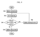
- FIG. 4 is a flowchart of a battery charging method according to a second exemplary embodiment of the present invention. As shown in the drawing, the charging unit 20 is connected to the battery pack 10 (S40).
- the charge control part 24 of the charging unit 20 measures the OCV of the battery module 12 (S42).
- the charge control part 24 may measure the OCV of the battery module 12 by the charging terminal b.
- the charge control part may include the coulomb counter measuring the charge, the temperature, the open circuit voltage, and the load cycle or time of the battery module 12.
- the charge control part 24 may determine whether the OCV of the battery module 12 is within the flat section IN.
- the OCV of the battery module 12 of the flat section IN with reference to FIG. 4 will now be described.
- FIG. 5 is a graph of an OCV of a battery charged by a battery charging method according to a second exemplary embodiment of the present invention.
- the OCV of the battery module 12 at the time t21 is V7.
- the charge control part 24 may determine whether the OCV of the battery module 12 is within the flat section IN by using a plurality of comparators.
- the charge control part 24 may set the reference voltage of a first input terminal of a comparator as the highest limitation value H and the lowest limitation value L, and may apply the OCV of the battery module 12 to a second input terminal of the comparator.
- the charge control part 24 may determine whether the OCV of the battery module 12 is within the flat section IN by using the output of the comparator.
- the charge control part 24 transmits the signal for starting the discharge of the battery module 12 (S46).
- the charge control part 24 transmits the signal for starting the charge of the battery module 12 (S48).
- the charge control part 24 measures the OCV of the battery module 12 at the time t22, when the measured OCV is less than the threshold value CP, the signal charging the battery module 12 may be transmitted to the battery management system.
Landscapes
- Engineering & Computer Science (AREA)
- Power Engineering (AREA)
- Secondary Cells (AREA)
- Charge And Discharge Circuits For Batteries Or The Like (AREA)
Abstract
Description
- The present invention relates to a battery charging device and a battery charging method for charging a battery pack. More particularly, the present invention relates to a battery charging device that effectively charges a battery, and a battery charging method.
- As the problem of environmental disruption and resource exhaustion occurs, interest in a system that can store power and that can efficiently use the stored power has increased. A power storage system may store generated power in a battery and supply power that is stored in this way to a load.
- A rechargeable battery capable of charging and discharging may be generally used for the power storage system in order to store power. The rechargeable battery differs from a primary battery in that it can be repeatedly charged and discharged, while the latter is incapable of being recharged. The rechargeable battery may be used as a single battery or a battery module in which a plurality of batteries are combined as a single unit, depending on the external devices to which it is applied.
- The present invention aims to provide a battery charging device in which battery charging is prevented in a flat section when charging the battery.
- According to an aspect of the invention, there is provided a battery charging device comprising a charging unit connectable to a battery pack, the battery pack comprising a battery module that includes at least one battery cell, and a charge control part arranged to receive information relating to the number of measurements in which an open circuit voltage OCV value of the battery module is determined to be within a predetermined voltage range, the charge control part being arranged to discharge the battery module if the number of measurements exceeds a predetermined threshold.
- The charge control part is arranged to discharge the battery module to make the OCV of the battery module lower than the lower boundary of a predetermined voltage range. The charge control part determines that the battery module is within a flat section if the number of measurements in which the OCV of the battery module is within a predetermined voltage range exceeds a predetermined threshold.
- When the OCV of the battery module is lower than the lower boundary, the charge control part may start to charge the battery module.
- The charge control part may be arranged to receive open circuit voltage information of the battery module, and to transmit a discharge start signal to the battery module when the number of measurements exceeds the predetermined threshold.
- The charge control part may be arranged to transmit a charging start signal to the battery module to charge the battery module if the open circuit voltage is outside the predetermined voltage range.
- The charging unit may include a charging terminal connected to the battery module and a coulomb counter measuring an open circuit voltage of the battery module by using the charging terminal and the charge control part may be arranged to transmit the discharge start signal in response to the open circuit voltage value as measured by the coulomb counter.
- If the measurement number is less than the predetermined number, the charge control part is arranged to continue to charge the battery module.
- The open circuit voltage may be periodically measured by a battery management system, the number of measurements being incremented when the periodic measurement indicates that the open circuit voltage is within the predetermined voltage range.
- According to a further aspect of the invention, there is provided a battery charging device comprising a charging unit connected to a battery module including at least one battery cell and charging the battery module and a charge control part measuring an open circuit voltage of the battery module and controlling the charging unit to discharge the battery module when the open circuit voltage value is within a predetermined voltage section.
- The charge control part may control the charging unit to charge the battery module if the open circuit voltage is outside the predetermined voltage section.
- According to a further aspect of the invention, there is provided a battery charging method comprising receiving number measurement information of which an open circuit voltage value of the battery module is determined within a predetermined voltage section from a battery management system managing a battery module including at least one battery cell; and transmitting a signal for discharging the battery module to the battery management system if it is determined that the number measurement exceeds a predetermined number.
- The battery charging method may further comprise receiving the open circuit voltage information of the battery module from the battery management system and generating the signal for discharging the battery module if the open circuit voltage is within the predetermined voltage section.
- The battery charging method may further comprise transmitting the signal charging the battery module to the battery management system if it is determined that the open circuit voltage is outside the predetermined voltage section from the open circuit voltage information.
- The battery charging method may further comprise transmitting the signal charging the battery module to the battery management system, if it is determined that the measurement number is less than the predetermined number.
- The measurement number includes a number of which the open circuit voltage within the predetermined voltage section is measured when the open circuit voltage is periodically measured by the battery management system.
- According to a still further aspect of the invention, there is provided a battery charging method comprising measuring an open circuit voltage of a battery module if the battery module including at least one battery cell is connected, transmitting a signal for discharging the battery module to a battery management system managing the battery module when the open circuit voltage is within a predetermined voltage section and transmitting a signal for charging the battery module to the battery management system if the open circuit voltage is outside the predetermined voltage section according to the discharge of the battery module.
- Embodiments of the invention will now be described by way of example with reference to the accompanying drawings, in which:
-
FIG. 1 is a block diagram of a battery charging system according to an exemplary embodiment of the present invention. -
FIG. 2 is a flowchart of a battery charging method according to a first exemplary embodiment of the present invention. -
FIG. 3 is a graph of an OCV of a battery charged by a battery charging method according to a first exemplary embodiment of the present invention. -
FIG. 4 is a flowchart of a battery charging method according to a second exemplary embodiment of the present invention. -
FIG. 5 is a graph of an OCV of a battery charged by a battery charging method according to a second exemplary embodiment of the present invention. - Referring to
FIG. 1 , abattery pack 10 may be connected to acharging unit 20. - The
battery pack 10 includes abattery module 12, a battery management system (hereafter referred to as "BMS") 14, amemory 16, arelay part 17, and adischarge load 18. - Firstly, the
battery module 12 may include a plurality of battery cells connected in series or in parallel and that are capable of being charged and discharged. Here, each cell may be a nickel-cadmium battery, a lead storage battery, a nickel-hydrogen battery, a lithium-ion battery, a lithium polymer battery and the like. The type of battery cell is not limited to the above list. - Also, the battery cell may be a cylindrical battery, a prismatic battery, a pouch battery or equivalent. However, the shape of the battery cell is not limited to this list. The plurality of battery cells form one
battery module 12, and may be used as a power source of an electric vehicle or a hybrid vehicle. Further, thebattery pack 10 includes a pack terminal a, and the pack terminal a may be connected to acharging part 22 of thecharging unit 20 to charge thebattery module 12. - Also, the
BMS 14 to efficiently manage the charge and discharge operation of thebattery module 12 is provided. TheBMS 14 manages the charge and discharge of thebattery module 12, and may measure open circuit voltage (hereafter referred to as "OCV"), current, temperature, etc., of each battery cell. Here, the OCV measures the voltage in a no-load state such that thedischarge load 18 is not operated when measuring the OCV of the battery cell. - The
BMS 14 measures the OCV, the current, the temperature, load cycle etc., of each battery cell, thereby estimating the OCV of the entire battery module, a state of charge (hereafter referred to as "SOC") of each cell, and a state of health (hereafter referred to as "SOH"), and storing the OCV of the entire battery module, the SOC and the SOH of each battery cell, the current, and the temperature of each battery cell to thememory 16 or transmitting them to thecharging unit 20 connected by wire or wirelessly. - In this case, the
BMS 14 may include a coulomb counter measuring the charge of each battery cell. - Also, the
BMS 14 may determine whether the OCV of thebattery module 12 is changed within a flat section (ie. within a predetermined voltage range). For example, theBMS 14 may periodically measure the OCV of thebattery module 12. - Also, the
BMS 14 accumulates the number of times that the measured OCV falls within the flat section. The flat section is a region in which the amount of change of the OCV for the change in the SOC is no more than a predetermined threshold value in a SOC-OCV relation curve. For example, the OCV of a battery may stay within a predetermined range (close to the nominal battery voltage) over a range of charge states from fully charged down to relatively deeply discharged, before it begins to fall much more steeply as the battery is further discharged. Instead of the SOC, other factors such as a charging current, a discharge current, a charging elapsed time, a discharge elapsed time etc, may be used. - That is, while the power of the
battery module 12 is used, when the OCV that is periodically measured is within the flat section, theBMS 14 may accumulate the number of times that the OCV is measured within the flat section and store it to thememory 16. - Also, according to the control of the
BMS 14, therelay part 17 may perform a switching operation of connecting thebattery module 12 and the pack terminal a, or electrically connecting thebattery module 12 and thedischarge load 18. - Next, the
discharge load 18 as a load consuming the power stored in thebattery module 12 is connected to thebattery module 12 by the switching operation of therelay part 17, thereby discharging thebattery module 12. - The
charging unit 20 includes thecharging part 22 and acharge control part 24. Thecharging unit 20 may charge thebattery pack 10. - The charging
part 22 charges thebattery pack 10 and includes a charging terminal b. Thecharging part 22 charges thebattery pack 10 if the charging terminal b is connected to the pack terminal a of thebattery pack 10. At this time, a positive terminal of thecharging part 22 may be connected to a positive terminal of thebattery pack 10, and a negative terminal of thecharging part 22 may be connected to a negative terminal of thebattery pack 10. - Thus, the
charging part 22 supplies power supplied to an outer terminal c connected to an external power source to thebattery module 12 to charge thebattery pack 10. - The
charge control part 24 may charge or discharge thebattery module 12 through thecharging part 22 if the charging terminal b is connected to the pack terminal a of thebattery pack 10. Also, thecharge control part 24 may receive information regarding the voltage, the current, and the temperature of eachbattery pack 10, the OCV, the SOH, and the SOC of thebattery module 12, or the OCV change of thebattery module 12 from theBMS 14 of the battery cell. - The
BMS 14 and thecharge control part 24 may include at least one of application specific integrated circuits (ASICs), digital signal processors (DSPs), digital signal processing devices (DSPDs), programmable logic devices (PLDs), field programmable gate arrays (FPGAs), processors, controllers, micro-controllers, microprocessors, and units to perform other functions. - Next, a method of charging the
battery module 12 according to the number of times that the OCV of thebattery module 12 is changed will be described with reference toFIG. 2. FIG. 2 is a flowchart of a battery charging method according to a first exemplary embodiment of the present invention. Thebattery pack 10 is connected to the load, thereby supplying the power stored to thebattery pack 10 to the load. The load may be various electrical devices consuming power such as home appliances or factory production equipment. - Firstly, the
BMS 14 measures the OCV of the battery module 12 (S10). At this time, theBMS 14 periodically measures the OCV of thebattery module 12, as described inFIG. 1 . Thus, theBMS 14 determines whether the power is consumed by the load such that the decreased OCV of thebattery module 12 is within a flat section IN (S12). Usage within the flat section IN will be described with reference toFIG. 3 . -
FIG. 3 is a graph of an OCV of a battery charged by a battery charging method according to a first exemplary embodiment of the present invention. As shown in the drawing, theBMS 14 may measure the OCV of thebattery module 12 with an interval of a predetermined time tIN. - The
BMS 14 may initially measure the OCV of thebattery module 12 at a time t10, and may measure the OCV of thebattery module 12 at a time t11 after the predetermined time tIN from the time t10. Also, theBMS 14 may measure the OCV of thebattery module 12 at a time t12 after the time t11 by the predetermined time tIN, a time t13 after the time t12 by the predetermined time tIN, and a time t14 after the time t13 by the predetermined time interval tIN. - Firstly, at the time t10, the OCV of the
battery module 12 may be measured as V1. At the time t10, if thebattery pack 10 is connected to the load and the power stored in thebattery module 12 is used, the OCV of thebattery pack 10 will decrease. That is, by the use of the power, the OCV of thebattery module 12 of the time t11 is decreased to V2. - Since the OCV is decreased from V1 to V2, the
BMS 14 may determine whether the power usage from the time t10 to the time t11 results in the OCV remaining within the predetermined voltage range within the flat section IN (between V=H and V=L). - Next, from the time t11 to the time t12, since the OCV of the
battery module 12 is decreased from V2 to V3, theBMS 14 may determine whether the OCV from the time t11 to the time t12 is within the flat section IN. - From the time t12 to the time t13, since the OCV of the
battery module 12 is decreased from V3 to V4, theBMS 14 may determine whether the OCV from the time t12 to the time t13 is within the flat section IN. - From the time t13 to the time t14, since the OCV of the
battery module 12 is decreased from V4 to V5, theBMS 14 may determine whether the OCV from the time t13 to the time t14 is within the flat section IN. - Thus, since the OCV of the
battery module 12 measured from the time t10 to the time t14 is within the flat section IN, theBMS 14 records the number of instances of power usage (the usage number) within the flat section IN as a total of four (S14) and stores the usage number to the memory 16 (S16). - Next, the
BMS 14 determines whether thebattery pack 10 is connected to the charging unit 20 (S18). For example, the connection of the chargingunit 20 may be determined through a sensor (not shown) sensing whether the charging terminal b is connected to the pack terminal a. Also, in a case that thebattery pack 10 and the chargingunit 20 are wirelessly connected, theBMS 14 may determine the connection of the chargingunit 20 when receiving an initial connection start signal for a wireless power change. - Further, the
BMS 14 transmits the usage number stored to thememory 16 to the charging unit 20 (S20). TheBMS 14 and the chargingunit 20 may be connected through a separate terminal or a wireless communication network as well as the connection between the pack terminal a and the charging terminal b. - On the other hand, the
BMS 14 may also transmit the OCV information V6 of thebattery module 12 at the time t15 to thecharge control part 24. However, when the measuring of the OCV of thebattery module 12 is possible through the charging terminal b of the chargingunit 20, the transmission of the OCV information V6 of thebattery module 12 may be omitted. - Thus, the
charge control part 24 determines whether the usage number exceeds a predetermined number (S22). For example, the predetermined number may be set as 3 times. - When the usage number exceeds the predetermined number, the
charge control part 24 transmits a signal for starting the discharge of the battery module 12 (S24). Thecharge control part 24 may transmit the signal for starting the discharge of thebattery module 12 to theBMS 14 to discharge thebattery module 12. Also, thecharge control part 24 appropriately controls the chargingpart 22 to discharge thebattery module 12.
At this time, thecharge control part 24 may discharge thebattery module 12 by further considering the OCV of thebattery module 12. - For example, in a case that the
charge control part 24 receives information for the current OCV of thebattery module 12 from theBMS 14 or measures the current OCV of thebattery module 12 through the charging terminal b, if the OCV of thebattery module 12 is less than a lowest limitation value L of the flat section, the usage number is not determined, and a signal for starting the charge of thebattery module 12 may be transmitted toBMS 14 S32. - Further, if the OCV of the
battery module 12 is greater than the lowest limitation value L of the flat section, thecharge control part 24 determines whether the usage number exceeds the predetermined number, and if the usage number exceeds the predetermined number, thecharge control part 24 transmits the discharge start signal to theBMS 14, thereby discharging thebattery module 12. - When the
charge control part 24 transmits the signal starting the discharge of thebattery module 12 to theBMS 14, theBMS 14 controls the switching operation of therelay part 17 to discharge the battery module 12 (S26) so as to connect thebattery module 12 to thedischarge load 18. - At the time t15 of
FIG. 3 , if the chargingunit 20 and thebattery pack 10 are connected, the step S20 to the step S23 are performed, and thecharge control part 24 may transmit the signal for discharging the power stored to thebattery module 12 to theBMS 14. - Also, when the usage number is less than the predetermined number, the
charge control part 24 may transmit the signal for starting the charge of thebattery module 12 to the BMS 14 (S32). - After the discharge is started, the
BMS 14 transmits the information for the OCV of thebattery module 12 to the charge control part 24 (S28). If the measuring of the OCV of thebattery module 12 is possible by the charging terminal b of the chargingunit 20, the step S28 may be omitted. - Thus, the
charge control part 24 determines whether the OCV of thebattery module 12 leaves the flat section IN (S30). For example, since the power stored to thebattery module 12 is discharged, thecharge control part 24 may determine whether the OCV of thebattery module 12 is less than a threshold value CP. - When it is determined that the OCV of the
battery module 12 is less than the threshold value CP of the flat section IN, thecharge control part 24 starts the charge of the battery module 12 (S30). At the time t16 ofFIG. 3 , thecharge control part 24 may transmit the signal for starting the charge of thebattery module 12 to theBMS 14 and supply the power to thebattery module 12 through the chargingpart 22. - Thus, the
BMS 14 controls the switching operation of therelay part 17 to charge thebattery module 12 so as to connect thebattery module 12 to the pack terminal a (S34). Next, the chargingunit 20 measuring the OCV of thebattery module 12 and charging thebattery module 12 will be described with reference toFIG. 4 . -
FIG. 4 is a flowchart of a battery charging method according to a second exemplary embodiment of the present invention. As shown in the drawing, the chargingunit 20 is connected to the battery pack 10 (S40). - The
charge control part 24 of the chargingunit 20 measures the OCV of the battery module 12 (S42). For example, thecharge control part 24 may measure the OCV of thebattery module 12 by the charging terminal b. At this time, the charge control part may include the coulomb counter measuring the charge, the temperature, the open circuit voltage, and the load cycle or time of thebattery module 12. - Thus, the
charge control part 24 may determine whether the OCV of thebattery module 12 is within the flat section IN. The OCV of thebattery module 12 of the flat section IN with reference toFIG. 4 will now be described. -
FIG. 5 is a graph of an OCV of a battery charged by a battery charging method according to a second exemplary embodiment of the present invention. As shown in the drawing, the OCV of thebattery module 12 at the time t21 is V7. The voltage value V7 may be determined as a value within the flat section IN (between V=H and V=L). - For example, the
charge control part 24 may determine whether the OCV of thebattery module 12 is within the flat section IN by using a plurality of comparators. Thecharge control part 24 may set the reference voltage of a first input terminal of a comparator as the highest limitation value H and the lowest limitation value L, and may apply the OCV of thebattery module 12 to a second input terminal of the comparator. Thus, thecharge control part 24 may determine whether the OCV of thebattery module 12 is within the flat section IN by using the output of the comparator. - Next, when the OCV of the
battery module 12 is within the flat section IN, thecharge control part 24 transmits the signal for starting the discharge of the battery module 12 (S46). - Next, when it is determined that the OCV of the
battery module 12 leaves the flat section IN according to the discharge, thecharge control part 24 transmits the signal for starting the charge of the battery module 12 (S48). - For example, the
charge control part 24 measures the OCV of thebattery module 12 at the time t22, when the measured OCV is less than the threshold value CP, the signal charging thebattery module 12 may be transmitted to the battery management system. - While this invention has been described in connection with what are presently considered to be practical exemplary embodiments, it is to be understood that the invention is not limited to the disclosed embodiments, but, on the contrary, is intended to cover various modifications and equivalent arrangements included within the scope of the appended claims.
Claims (14)
- A battery charging device (20) comprising:a charging unit (22) connectable to a battery pack, the battery pack comprising a battery module (12) that includes at least one battery cell; anda charge control part (24) arranged to receive information relating to the number of measurements in which an open circuit voltage OCV value of the battery module (12) is determined to be within a predetermined voltage range;the charge control part being arranged to discharge the battery module if the number of measurements exceeds a predetermined threshold.
- The battery charging device of claim 1, wherein
the charge control part is arranged to receive open circuit voltage information of the battery module, and to transmit a discharge start signal to the battery module when the open circuit voltage is within the predetermined voltage range. - The battery charging device of claim 2, wherein
the charge control part is arranged to transmit a charging start signal to the battery module to charge the battery module if the open circuit voltage is outside the predetermined voltage range. - The battery charging device of claim 1, 2 or 3, wherein:the charging unit includes a charging terminal connected to the battery module and a coulomb counter measuring an open circuit voltage of the battery module by using the charging terminal; andthe charge control part is arranged to transmit the discharge start signal in response to the open circuit voltage value as measured by the coulomb counter.
- The battery charging device of any one of the preceding claims, wherein
if the measurement number is less than the predetermined number, the charge control part is arranged to transmit a charging start signal to charge the battery module. - The battery charging device of any one of the preceding claims, wherein the open circuit voltage is periodically measured by a battery management system, the number of measurements being incremented when the periodic measurement indicates that the open circuit voltage is within the predetermined voltage range.
- A battery charging device comprising:a charging unit connected to a battery module including at least one battery cell and charging the battery module; anda charge control part measuring an open circuit voltage of the battery module and controlling the charging unit to discharge the battery module when the open circuit voltage value is within a predetermined voltage section.
- The battery charging device of claim 7, wherein
the charge control part controls the charging unit to charge the battery module if the open circuit voltage is outside the predetermined voltage section. - A battery charging method comprising:receiving number measurement information of which an open circuit voltage value of the battery module is determined within a predetermined voltage section from a battery management system managing a battery module including at least one battery cell; andtransmitting a signal for discharging the battery module to the battery management system if it is determined that the number measurement exceeds a predetermined number.
- The battery charging method of claim 9, further comprising:receiving the open circuit voltage information of the battery module from the battery management system; andgenerating the signal for discharging the battery module if the open circuit voltage is within the predetermined voltage section.
- The battery charging method of claim 10, further comprising
transmitting the signal charging the battery module to the battery management system if it is determined that the open circuit voltage is outside the predetermined voltage section from the open circuit voltage information. - The battery charging method of claim 9, further comprising
transmitting the signal charging the battery module to the battery management system, if it is determined that the measurement number is less than the predetermined number. - The battery charging method of claim 9, wherein
the measurement number includes a number of which the open circuit voltage within the predetermined voltage section is measured when the open circuit voltage is periodically measured by the battery management system. - A battery charging method comprising:measuring an open circuit voltage of a battery module if the battery module including at least one battery cell is connected;transmitting a signal for discharging the battery module to a battery management system managing the battery module when the open circuit voltage is within a predetermined voltage section; andtransmitting a signal for charging the battery module to the battery management system if the open circuit voltage is outside the predetermined voltage section according to the discharge of the battery module.
Applications Claiming Priority (1)
| Application Number | Priority Date | Filing Date | Title |
|---|---|---|---|
| KR1020140001441A KR20150081696A (en) | 2014-01-06 | 2014-01-06 | Battery charging device and battery charging method |
Publications (2)
| Publication Number | Publication Date |
|---|---|
| EP2892125A2 true EP2892125A2 (en) | 2015-07-08 |
| EP2892125A3 EP2892125A3 (en) | 2015-09-16 |
Family
ID=51987080
Family Applications (1)
| Application Number | Title | Priority Date | Filing Date |
|---|---|---|---|
| EP14195528.6A Withdrawn EP2892125A3 (en) | 2014-01-06 | 2014-11-28 | Battery charging device and battery charging method |
Country Status (3)
| Country | Link |
|---|---|
| US (1) | US20150194823A1 (en) |
| EP (1) | EP2892125A3 (en) |
| KR (1) | KR20150081696A (en) |
Families Citing this family (5)
| Publication number | Priority date | Publication date | Assignee | Title |
|---|---|---|---|---|
| CN110445213B (en) * | 2019-08-13 | 2022-05-17 | 深圳市道通智能航空技术股份有限公司 | A charging management system, method, device and storage medium |
| CN110729790B (en) * | 2019-10-28 | 2023-03-21 | Oppo广东移动通信有限公司 | Charging method and device, computer equipment and storage medium |
| KR20220037047A (en) | 2020-09-16 | 2022-03-24 | 주식회사 엘지에너지솔루션 | Battery pack and controlling method thereof |
| KR20220100332A (en) * | 2021-01-08 | 2022-07-15 | 주식회사 엘지에너지솔루션 | Battery apparatus and method of supplying voltage |
| KR20220117063A (en) * | 2021-02-16 | 2022-08-23 | 주식회사 엘지에너지솔루션 | Battery charge and discharge apparatus and method |
Family Cites Families (3)
| Publication number | Priority date | Publication date | Assignee | Title |
|---|---|---|---|---|
| JP3431867B2 (en) * | 1999-09-21 | 2003-07-28 | 松下電器産業株式会社 | Battery power supply device and electric equipment using the same |
| JP2008151526A (en) * | 2006-12-14 | 2008-07-03 | Matsushita Electric Ind Co Ltd | Secondary battery deterioration judgment device and backup power source |
| KR101084828B1 (en) * | 2009-10-12 | 2011-11-21 | 삼성에스디아이 주식회사 | How to control the charge of the battery pack |
-
2014
- 2014-01-06 KR KR1020140001441A patent/KR20150081696A/en not_active Withdrawn
- 2014-11-28 EP EP14195528.6A patent/EP2892125A3/en not_active Withdrawn
- 2014-12-18 US US14/575,961 patent/US20150194823A1/en not_active Abandoned
Non-Patent Citations (1)
| Title |
|---|
| None |
Also Published As
| Publication number | Publication date |
|---|---|
| EP2892125A3 (en) | 2015-09-16 |
| US20150194823A1 (en) | 2015-07-09 |
| KR20150081696A (en) | 2015-07-15 |
Similar Documents
| Publication | Publication Date | Title |
|---|---|---|
| US10873201B2 (en) | Battery management apparatus and method for protecting a lithium iron phosphate cell from over-voltage using the same | |
| US10291037B2 (en) | Electrical energy storage device including individually controlled energy cell slots | |
| US9444267B2 (en) | Cell voltage equalizer for multi-cell battery pack which determines the waiting time between equalization operations based on the voltage difference and the state of charge level | |
| JP5363740B2 (en) | Charge control circuit, battery pack, and charging system | |
| CN101192757B (en) | Charging system, charging device and battery pack | |
| CN104471414B (en) | Battery control device | |
| US20100102778A1 (en) | Charging system, charger, and battery pack | |
| WO2016051722A1 (en) | Electric power storage device, control device, electric power storage system, method for controlling electric power storage device, and non-transitory computer-readable medium storing control program | |
| US9184600B2 (en) | Method for balancing the voltages of electrochemical cells connected in several parallel branches | |
| KR20140048737A (en) | Battery pack and method of controlling the battery pack | |
| CN104977540A (en) | Method for monitoring a charge state or a charge or discharge current of a rechargeable battery | |
| US20110025272A1 (en) | Charging method, charging device, and battery pack | |
| US20240162721A1 (en) | System and method for using multiple high voltage battery packs in parallel | |
| US20150194823A1 (en) | Battery charging device and battery charging method | |
| KR102358435B1 (en) | Battery charging method and battery pack using the method | |
| CN115461911B (en) | Battery pack and battery pack control methods | |
| JP5165405B2 (en) | Charge control circuit, battery pack, and charging system | |
| KR102082382B1 (en) | Multi battery pack apparatus and control method for charging the same | |
| JP2009112180A (en) | Battery pack and control method thereof | |
| JP2021141701A (en) | Battery monitoring device | |
| US9466990B2 (en) | Method for enhancing a battery management system, battery management system, battery system and motor vehicle | |
| US8604754B2 (en) | Universal power interface bus | |
| KR101748643B1 (en) | Method and Apparatus for filtering measurement data of secondary battery pack | |
| US20140111162A1 (en) | Method for operating a storage device for storing electrical energy, and storage device for storing electrical energy | |
| KR102005398B1 (en) | Apparatus and method for setting full charging capacity |
Legal Events
| Date | Code | Title | Description |
|---|---|---|---|
| PUAI | Public reference made under article 153(3) epc to a published international application that has entered the european phase |
Free format text: ORIGINAL CODE: 0009012 |
|
| 17P | Request for examination filed |
Effective date: 20141128 |
|
| AK | Designated contracting states |
Kind code of ref document: A2 Designated state(s): AL AT BE BG CH CY CZ DE DK EE ES FI FR GB GR HR HU IE IS IT LI LT LU LV MC MK MT NL NO PL PT RO RS SE SI SK SM TR |
|
| AX | Request for extension of the european patent |
Extension state: BA ME |
|
| PUAL | Search report despatched |
Free format text: ORIGINAL CODE: 0009013 |
|
| AK | Designated contracting states |
Kind code of ref document: A3 Designated state(s): AL AT BE BG CH CY CZ DE DK EE ES FI FR GB GR HR HU IE IS IT LI LT LU LV MC MK MT NL NO PL PT RO RS SE SI SK SM TR |
|
| AX | Request for extension of the european patent |
Extension state: BA ME |
|
| RIC1 | Information provided on ipc code assigned before grant |
Ipc: H02J 7/00 20060101AFI20150811BHEP |
|
| R17P | Request for examination filed (corrected) |
Effective date: 20160316 |
|
| RBV | Designated contracting states (corrected) |
Designated state(s): AL AT BE BG CH CY CZ DE DK EE ES FI FR GB GR HR HU IE IS IT LI LT LU LV MC MK MT NL NO PL PT RO RS SE SI SK SM TR |
|
| STAA | Information on the status of an ep patent application or granted ep patent |
Free format text: STATUS: THE APPLICATION HAS BEEN WITHDRAWN |
|
| 18W | Application withdrawn |
Effective date: 20160616 |