EP2892084A1 - Cable-type packaging for secondary batteries and cable-type secondary batteries comprising same - Google Patents
Cable-type packaging for secondary batteries and cable-type secondary batteries comprising same Download PDFInfo
- Publication number
- EP2892084A1 EP2892084A1 EP13833323.2A EP13833323A EP2892084A1 EP 2892084 A1 EP2892084 A1 EP 2892084A1 EP 13833323 A EP13833323 A EP 13833323A EP 2892084 A1 EP2892084 A1 EP 2892084A1
- Authority
- EP
- European Patent Office
- Prior art keywords
- layer
- cable
- active material
- metal foil
- polymer resin
- Prior art date
- Legal status (The legal status is an assumption and is not a legal conclusion. Google has not performed a legal analysis and makes no representation as to the accuracy of the status listed.)
- Granted
Links
Images

Classifications
-
- H—ELECTRICITY
- H01—ELECTRIC ELEMENTS
- H01M—PROCESSES OR MEANS, e.g. BATTERIES, FOR THE DIRECT CONVERSION OF CHEMICAL ENERGY INTO ELECTRICAL ENERGY
- H01M4/00—Electrodes
- H01M4/02—Electrodes composed of, or comprising, active material
- H01M4/64—Carriers or collectors
- H01M4/66—Selection of materials
- H01M4/661—Metal or alloys, e.g. alloy coatings
-
- H—ELECTRICITY
- H01—ELECTRIC ELEMENTS
- H01M—PROCESSES OR MEANS, e.g. BATTERIES, FOR THE DIRECT CONVERSION OF CHEMICAL ENERGY INTO ELECTRICAL ENERGY
- H01M10/00—Secondary cells; Manufacture thereof
- H01M10/04—Construction or manufacture in general
- H01M10/0422—Cells or battery with cylindrical casing
-
- H—ELECTRICITY
- H01—ELECTRIC ELEMENTS
- H01M—PROCESSES OR MEANS, e.g. BATTERIES, FOR THE DIRECT CONVERSION OF CHEMICAL ENERGY INTO ELECTRICAL ENERGY
- H01M10/00—Secondary cells; Manufacture thereof
- H01M10/04—Construction or manufacture in general
- H01M10/0436—Small-sized flat cells or batteries for portable equipment
-
- H—ELECTRICITY
- H01—ELECTRIC ELEMENTS
- H01M—PROCESSES OR MEANS, e.g. BATTERIES, FOR THE DIRECT CONVERSION OF CHEMICAL ENERGY INTO ELECTRICAL ENERGY
- H01M10/00—Secondary cells; Manufacture thereof
- H01M10/05—Accumulators with non-aqueous electrolyte
- H01M10/052—Li-accumulators
-
- H—ELECTRICITY
- H01—ELECTRIC ELEMENTS
- H01M—PROCESSES OR MEANS, e.g. BATTERIES, FOR THE DIRECT CONVERSION OF CHEMICAL ENERGY INTO ELECTRICAL ENERGY
- H01M4/00—Electrodes
- H01M4/02—Electrodes composed of, or comprising, active material
- H01M4/64—Carriers or collectors
- H01M4/70—Carriers or collectors characterised by shape or form
- H01M4/75—Wires, rods or strips
-
- H—ELECTRICITY
- H01—ELECTRIC ELEMENTS
- H01M—PROCESSES OR MEANS, e.g. BATTERIES, FOR THE DIRECT CONVERSION OF CHEMICAL ENERGY INTO ELECTRICAL ENERGY
- H01M50/00—Constructional details or processes of manufacture of the non-active parts of electrochemical cells other than fuel cells, e.g. hybrid cells
- H01M50/10—Primary casings; Jackets or wrappings
- H01M50/116—Primary casings; Jackets or wrappings characterised by the material
- H01M50/117—Inorganic material
- H01M50/119—Metals
-
- H—ELECTRICITY
- H01—ELECTRIC ELEMENTS
- H01M—PROCESSES OR MEANS, e.g. BATTERIES, FOR THE DIRECT CONVERSION OF CHEMICAL ENERGY INTO ELECTRICAL ENERGY
- H01M50/00—Constructional details or processes of manufacture of the non-active parts of electrochemical cells other than fuel cells, e.g. hybrid cells
- H01M50/10—Primary casings; Jackets or wrappings
- H01M50/116—Primary casings; Jackets or wrappings characterised by the material
- H01M50/121—Organic material
-
- H—ELECTRICITY
- H01—ELECTRIC ELEMENTS
- H01M—PROCESSES OR MEANS, e.g. BATTERIES, FOR THE DIRECT CONVERSION OF CHEMICAL ENERGY INTO ELECTRICAL ENERGY
- H01M50/00—Constructional details or processes of manufacture of the non-active parts of electrochemical cells other than fuel cells, e.g. hybrid cells
- H01M50/10—Primary casings; Jackets or wrappings
- H01M50/116—Primary casings; Jackets or wrappings characterised by the material
- H01M50/124—Primary casings; Jackets or wrappings characterised by the material having a layered structure
-
- H—ELECTRICITY
- H01—ELECTRIC ELEMENTS
- H01M—PROCESSES OR MEANS, e.g. BATTERIES, FOR THE DIRECT CONVERSION OF CHEMICAL ENERGY INTO ELECTRICAL ENERGY
- H01M50/00—Constructional details or processes of manufacture of the non-active parts of electrochemical cells other than fuel cells, e.g. hybrid cells
- H01M50/10—Primary casings; Jackets or wrappings
- H01M50/116—Primary casings; Jackets or wrappings characterised by the material
- H01M50/124—Primary casings; Jackets or wrappings characterised by the material having a layered structure
- H01M50/126—Primary casings; Jackets or wrappings characterised by the material having a layered structure comprising three or more layers
- H01M50/129—Primary casings; Jackets or wrappings characterised by the material having a layered structure comprising three or more layers with two or more layers of only organic material
-
- Y—GENERAL TAGGING OF NEW TECHNOLOGICAL DEVELOPMENTS; GENERAL TAGGING OF CROSS-SECTIONAL TECHNOLOGIES SPANNING OVER SEVERAL SECTIONS OF THE IPC; TECHNICAL SUBJECTS COVERED BY FORMER USPC CROSS-REFERENCE ART COLLECTIONS [XRACs] AND DIGESTS
- Y02—TECHNOLOGIES OR APPLICATIONS FOR MITIGATION OR ADAPTATION AGAINST CLIMATE CHANGE
- Y02E—REDUCTION OF GREENHOUSE GAS [GHG] EMISSIONS, RELATED TO ENERGY GENERATION, TRANSMISSION OR DISTRIBUTION
- Y02E60/00—Enabling technologies; Technologies with a potential or indirect contribution to GHG emissions mitigation
- Y02E60/10—Energy storage using batteries
-
- Y—GENERAL TAGGING OF NEW TECHNOLOGICAL DEVELOPMENTS; GENERAL TAGGING OF CROSS-SECTIONAL TECHNOLOGIES SPANNING OVER SEVERAL SECTIONS OF THE IPC; TECHNICAL SUBJECTS COVERED BY FORMER USPC CROSS-REFERENCE ART COLLECTIONS [XRACs] AND DIGESTS
- Y02—TECHNOLOGIES OR APPLICATIONS FOR MITIGATION OR ADAPTATION AGAINST CLIMATE CHANGE
- Y02P—CLIMATE CHANGE MITIGATION TECHNOLOGIES IN THE PRODUCTION OR PROCESSING OF GOODS
- Y02P70/00—Climate change mitigation technologies in the production process for final industrial or consumer products
- Y02P70/50—Manufacturing or production processes characterised by the final manufactured product
Definitions
- the present invention relates to a packaging for a cable-type secondary battery and a cable-type secondary battery comprising the packaging, and more particularly to a packaging for a cable-type secondary battery, which can inhibit the contamination of an electrolyte solution present within the battery to prevent the deterioration of battery performances, and a cable-type secondary battery comprising the packaging.
- Secondary batteries are devices capable of storing energy in chemical form and of converting into electrical energy to generate electricity when needed.
- the secondary batteries are also referred to as rechargeable batteries because they can be recharged repeatedly.
- Common secondary batteries include lead accumulators, NiCd batteries, NiMH accumulators, Li-ion batteries, Li-ion polymer batteries, and the like. When compared with disposable primary batteries, not only are the secondary batteries more economically efficient, they are also more environmentally friendly.
- Secondary batteries are currently used in applications requiring low electric power, for example, equipment to start vehicles, mobile devices, tools, uninterruptible power supplies, and the like. Recently, as the development of wireless communication technologies has been leading to the popularization of mobile devices and even to the mobilization of many kinds of conventional devices, the demand for secondary batteries has been dramatically increasing. Secondary batteries are also used in environmentally friendly next-generation vehicles such as hybrid vehicles and electric vehicles to reduce the costs and weight and to increase the service life of the vehicles.
- secondary batteries have a cylindrical, prismatic, or pouch shape. This is associated with a fabrication process of the secondary batteries in which an electrode assembly composed of an anode, a cathode, and a separator is mounted in a cylindrical or prismatic metal casing or a pouch-shaped casing of an aluminum laminate sheet, and in which the casing is filled with electrolyte. Because a predetermined mounting space for the electrode assembly is necessary in this process, the cylindrical, prismatic or pouch shape of the secondary batteries is a limitation in developing various shapes of mobile devices. Accordingly, there is a need for secondary batteries of a new structure that are easily adaptable in shape.
- the present invention is designed to solve the above-mentioned problems, and therefore it is an object of the present invention to provide a packaging for a cable-type battery, which can prevent the contamination of an electrolyte in the cable-type battery and prevent the deterioration of battery performances.
- a packaging for a cable-type secondary battery extending longitudinally, comprising: a hollow metal foil layer; a first polymer resin layer formed on one surface of the metal foil layer; and a second polymer resin layer formed on the other surface of the metal foil layer.
- the metal foil layer may comprise any one selected from the group consisting of iron (Fe), carbon (C), chrome (Cr), manganese (Mn), nickel (Ni), copper (Cu), aluminum (Al), an equivalent thereof and an alloy of two or more thereof.
- the first polymer resin layer may comprise any one selected from the group consisting of polyolefin resins, polyester resins, polyamide resins, fluoro-containing resins and a mixture thereof.
- the second polymer resin layer may comprise any one selected from the group consisting of polyolefin resins, polyester resins, fluoro-containing resins and a mixture thereof.
- the polyolefin resins may be any one selected from the group consisting of a copolymer of polypropylene-acrylic acid, a copolymer of polyethylene-acrylic acid, polypropylene chloride, a terpolymer of polypropylene-butylene-ethylene, polyethylene, a copolymer of ethylene-propylene, and a mixture thereof.
- first polymer resin layer or the second polymer resin layer may further comprise hydrophobic inorganic particles.
- the hydrophobic inorganic particles may be obtained from any one selected from the group consisting of SiO 2 , Al 2 O 3 , MgO, BaTiO 3 , ZrO 2 , ZnO and a mixture thereof.
- the hydrophobic inorganic particles may have an average particle diameter of 1 nm to 5 ⁇ m.
- a layer of hydrophobic inorganic particles may be further formed between the metal foil layer and the first polymer resin layer, or between the metal foil layer and the second polymer resin layer, or on the other surface of the second polymer resin layer whose one surface is faced to the metal foil layer.
- the layer of hydrophobic inorganic particles may comprise any one selected from the group consisting of SiO 2 , Al 2 O 3 , MgO, BaTiO 3 , ZrO 2 , ZnO and a mixture thereof.
- a cable-type secondary battery comprising: an electrode assembly having a horizontal cross section of a predetermined shape and extending longitudinally, which comprises an inner current collector, an inner electrode active material layer, an outer electrode active material layer, an electrolyte layer interposed between the inner electrode active material layer and the outer electrode active material layer, and an outer current collector foil formed on the outer surface of the outer electrode active material layer; and a packaging configured to surround the electrode assembly, wherein the packaging comprises a hollow metal foil layer; a first polymer resin layer formed on one surface of the metal foil layer; and a second polymer resin layer formed on the other surface of the metal foil layer.
- the outer current collector foil may be in the form of a half-pipe or a mesh.
- the outer current collector foil may be made of stainless steel, aluminum, nickel, titanium, sintered carbon, or copper; stainless steel treated with carbon, nickel, titanium or silver on the surface thereof; an aluminum-cadmium alloy; a non-conductive polymer treated with a conductive material on the surface thereof; or a conductive polymer.
- a cable-type secondary battery comprising: an electrode assembly having a horizontal cross section of a predetermined shape and extending longitudinally, which comprises an inner current collector, an inner electrode active material layer, an outer electrode active material layer, and an electrolyte layer interposed between the inner electrode active material layer and the outer electrode active material layer; and a packaging configured to surround the electrode assembly, wherein the packaging comprises a hollow metal foil layer acting as an outer current collector; a first polymer resin layer formed on one surface of the metal foil layer; and a second polymer resin layer formed at both ends of the other surface of the metal foil layer.
- the inner current collector may be made of stainless steel, aluminum, nickel, titanium, sintered carbon, or copper; stainless steel treated with carbon, nickel, titanium or silver on the surface thereof; an aluminum-cadmium alloy; a non-conductive polymer treated with a conductive material on the surface thereof; or a conductive polymer.
- an inner electrode and an outer electrode may be an anode and a cathode, respectively, and also they may be reversed.
- one of the inner electrode active material layer and the outer electrode active material layer may comprise an active material selected from the group consisting of natural graphite, artificial graphite, or carbonaceous material; lithium-titanium complex oxide (LTO), and metals (Me) including Si, Sn, Li, Zn, Mg, Cd, Ce, Ni and Fe; an alloy of the metals; an oxide (MeOx) of the metals; a complex of the metals and carbon; and a mixture thereof.
- an active material selected from the group consisting of natural graphite, artificial graphite, or carbonaceous material; lithium-titanium complex oxide (LTO), and metals (Me) including Si, Sn, Li, Zn, Mg, Cd, Ce, Ni and Fe; an alloy of the metals; an oxide (MeOx) of the metals; a complex of the metals and carbon; and a mixture thereof.
- one of the inner electrode active material layer and the outer electrode active material layer may comprise an active material selected from the group consisting of LiCoO 2 , LiNiO 2 , LiMn 2 O 4 , LiCoPO 4 , LiFePO 4 , LiNiMnCoO 2 , LiNi 1-x-y z Co x M1 y M2 z O 2 (wherein M1 and M2 are each independently selected from the group consisting of Al, Ni, Co, Fe, Mn, V, Cr, Ti, W, Ta, Mg and Mo, and x, y and z are each independently an atomic fraction of oxide-forming elements, in which 0 ⁇ x ⁇ 0.5, 0 ⁇ y ⁇ 0.5, 0 ⁇ z ⁇ 0.5, and x+y+z ⁇ 1), and a mixture thereof.
- M1 and M2 are each independently selected from the group consisting of Al, Ni, Co, Fe, Mn, V, Cr, Ti, W, Ta, Mg and Mo,
- the electrolyte layer may comprise an electrolyte selected from a gel polymer electrolyte using PEO, PVdF, PMMA, PAN, or PVAc; and a solid electrolyte of PEO, polypropylene oxide (PPO), polyether imine (PEI), polyethylene sulphide (PES), or polyvinyl acetate (PVAc).
- PEO polypropylene oxide
- PEI polyether imine
- PES polyethylene sulphide
- PVAc polyvinyl acetate
- the packaging of the present invention comprises a metal foil layer to prevent the contamination of an electrolyte in the cable-type battery and prevent the deterioration of battery performances, and also maintain the mechanical strength of the cable-type battery.
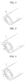
- FIG. 1 is a perspective view of a packaging for a cable-type secondary battery according to one embodiment of the present invention
- FIGS. 2 to 4 are each perspective views of packagings for a cable-type secondary battery according to other embodiments of the present invention.
- a packaging 10 for a cable-type secondary battery has a structure of extending longitudinally, and comprises a hollow metal foil layer 1; a first polymer resin layer 2 formed on one surface of the metal foil layer 1; and a second polymer resin layer 3 formed on the other surface of the metal foil layer 1.
- a general tube packaging made of a polymer material may cause the permeation of moisture or air into the polymer material to contaminate an electrolyte in batteries and deteriorate battery performances
- the packaging 10 for a cable-type secondary battery comprises the metal foil layer 1 to block the permeation of moisture or air into the polymer material, thereby preventing the contamination of an electrolyte in the cable-type battery and the deterioration of battery performances, and maintaining the mechanical strength of the cable-type battery.
- the metal foil layer 1 which functions to block the permeation of moisture or air from the outside into the inside, may comprise any one selected from the group consisting of iron (Fe), carbon (C), chrome (Cr), manganese (Mn), nickel (Ni), copper (Cu), aluminum (Al), an equivalent thereof and an alloy of two or more thereof, but the present invention is not limited thereto.
- iron can be used in the formation of the metal foil layer 1 to enhance mechanical strength
- aluminum can be used to provide good flexibility.
- an aluminum foil may be used.
- the first polymer resin layer 2 may comprise any one selected from the group consisting of polyolefin resins, polyester resins, polyamide resins, fluoro-containing resins and a mixture thereof.
- the first polymer resin layer 2 becomes the outermost layer, it is preferred that it is made of nylon or polyethylene terephthalate, but the present invention is not limited thereto.
- the first polymer resin layer 2 may act as the layer of a heat-shrinkable tube.
- the heat-shrinkable tube refers to a tube which is shrunk when heated to closely encase a terminal or a substance having a different shape or size. Such a heat-shrinkable tube is mostly made of a polymer resin and used for insulating or other purposes.
- commercially available heat-shrinkable tubes made of various materials and having various forms may be properly used according to the desired purpose.
- the heat-shrinkable tube is inserted in lithium ion batteries by using an automatic coating machine before heat shrinkage, it is necessary for the heat shrinkable tube to have hardness such that its opening can be opened and supported by itself.
- a shrinkage process is preferably carried out at a low temperature, for example, at a temperature of 70 to 200 °C, preferably 70 to 120 °C, so as to avoid the thermal damage of the lithium ion batteries.
- the heat-shrinkable tube may be made of polyolefins such as polyethylene and polypropylene, polyesters such as polyethylene terephthalate, and fluoro-containing resins such as polyvinylidene fluoride and polytetrafluoroethylene.
- the second polymer resin layer 3 may comprise any one selected from the group consisting of polyolefin resins, polyester resins, fluoro-containing resins and a mixture thereof.
- the second polymer resin layer 3 may act as the layer of a heat-shrinkable tube, similar to the first polymer resin layer 2, and examples thereof are the same as mentioned above.
- the second polymer resin layer 3 may act as an internal insulating layer, and in this case, the second polymer resin layer 3 may comprise any one selected from the group consisting of a copolymer of polypropylene-acrylic acid, a copolymer of polyethylene-acrylic acid, polypropylene chloride, a terpolymer of polypropylene-butylene-ethylene, polyethylene, a copolymer of ethylene-propylene, and a mixture thereof, but the present invention is not limited thereto.
- first polymer resin layer 2 or the second polymer resin layer 3 may further comprise hydrophobic inorganic particles.
- the hydrophobic inorganic particles may be obtained from any one selected from the group consisting of SiO 2 , Al 2 O 3 , MgO, BaTiO 3 , ZrO 2 , ZnO and a mixture thereof, but are not limited thereto.
- the hydrophobic inorganic particles may have an average particle diameter of 1 nm to 5 ⁇ m.
- the additional use of the hydrophobic inorganic particles can more enhance the insulation effect within batteries and can block the permeation of moisture into batteries to minimize the contamination of electrolyte components in the batteries, thereby preventing the deterioration of battery performances.
- packagings 11, 12, 13 for a cable-type secondary battery may each comprise a layer 4 of hydrophobic inorganic particles between the metal foil layer 1 and the first polymer resin layer 2, or between the metal foil layer 1 and the second polymer resin layer 3, or on the other surface of the second polymer resin layer 3 whose one surface is faced to the metal foil layer 1.
- the layer 4 of hydrophobic inorganic particles may further comprise a polymer selected from the group consisting of a copolymer of polypropylene-acrylic acid, a copolymer of polyethylene-acrylic acid, polypropylene chloride, a terpolymer of polypropylene-butylene-ethylene, polyethylene, a copolymer of ethylene-propylene, and a mixture thereof, in addition to hydrophobic inorganic particles.
- Examples of usable hydrophobic inorganic particles are the same as mentioned above.
- the additional use of the hydrophobic inorganic particles can more enhance the insulation effect within batteries and can block the permeation of moisture into batteries to minimize the contamination of electrolyte components in the batteries, thereby preventing the deterioration of battery performances.
- FIG. 5 shows a cross-section of a cable-type secondary battery according to one embodiment of the present invention
- FIG. 6 shows a longitudinal section of a cable-type secondary battery according to another embodiment of the present invention.
- a cable-type secondary battery 100 comprises an electrode assembly 20 having a horizontal cross section of a predetermined shape and extending longitudinally, which comprises an inner current collector 5, an inner electrode active material layer 6, an outer electrode active material layer 8, an electrolyte layer 7 interposed between the inner electrode active material layer 6 and the outer electrode active material layer 8, and an outer current collector foil 9 formed on the outer surface of the outer electrode active material layer 8; and a packaging 10 configured to closely surround the electrode assembly 20, wherein the packaging 10 comprises a hollow metal foil layer 1; a first polymer resin layer 2 formed on one surface of the metal foil layer 1; and a second polymer resin layer 3 formed on the other surface of the metal foil layer 1.
- the term 'a predetermined shape' used herein refers to not being particularly limited to any shape, and means that any shape that does not damage the nature of the present invention is possible.
- the cable-type secondary battery 100 of the present invention has a horizontal cross section of a predetermined shape, a linear structure, which extends in the longitudinal direction, and flexibility, so it can freely change in shape.
- the outer current collector foil 9 may be in the form of a half-pipe or a mesh, or may consist of a coating layer of a metal paste.
- the current collector is a half-pipe form, two or three current collectors are used to adhere to the packaging, so that the outer surface of the electrode assembly is completely surrounded by them.
- the current collectors are preferably disposed to maintain regular intervals.
- the current collector is a mesh form, a certain degree of stretching property can be obtained. Therefore, such a form of the current collector may be cut and used to completely surround the outer surface of the electrode assembly.
- the current collector is made of a metal paste
- the metal paste is coated on the inner surface of the packaging to form the current collector.
- the outer current collector foil 9 may be made of stainless steel, aluminum, nickel, titanium, sintered carbon, or copper; stainless steel treated with carbon, nickel, titanium or silver on the surface thereof; an aluminum-cadmium alloy; a non-conductive polymer treated with a conductive material on the surface thereof; or a conductive polymer.
- the conductive material may include polyacetylene, polyaniline, polypyrrole, polythiophene, polysulfurnitride, indium tin oxide (ITO), copper, silver, palladium and nickel.
- Example of the conductive polymer may include polyacetylene, polyaniline, polypyrrole, polythiophene and polysulfurnitride.
- a cable-type secondary battery 110 comprises an electrode assembly 21 having a horizontal cross section of a predetermined shape and extending longitudinally, which comprises an inner current collector 5, an inner electrode active material layer 6, an outer electrode active material layer 8, and an electrolyte layer 7 interposed between the inner electrode active material layer 6 and the outer electrode active material layer 8; and a packaging 14 configured to closely surround the electrode assembly 21, wherein the packaging 14 comprises a hollow metal foil layer 1 acting as an outer current collector; a first polymer resin layer 2 formed on one surface of the metal foil layer 1; and a second polymer resin layer 3 formed at both ends of the other surface of the metal foil layer 1.
- the metal foil layer 1 blocks the permeation of moisture or air into batteries and maintains the mechanical strength of the packaging, and also acts as an outer current electrode. Accordingly, it needs no additional outer current electrode, and thus is advantageous in terms of economic effects.
- the second polymer resin layer may act as a heat-shrinkable tube layer or an inner insulation layer at both ends of the cable-type secondary battery, the sealability or insulating property of the cable-type secondary battery can be enhanced.
- the inner current collector 5 may be made of stainless steel, aluminum, nickel, titanium, sintered carbon, or copper; stainless steel treated with carbon, nickel, titanium or silver on the surface thereof; an aluminum-cadmium alloy; a non-conductive polymer treated with a conductive material on the surface thereof; or a conductive polymer, but is not limited thereto.
- the conductive material may include polyacetylene, polyaniline, polypyrrole, polythiophene, polysulfurnitride, indium tin oxide (ITO), copper, silver, palladium and nickel.
- Example of the conductive polymer may include polyacetylene, polyaniline, polypyrrole, polythiophene and polysulfurnitride. But the present invention is not limited thereto.
- an inner electrode and an outer electrode may be an anode and a cathode, respectively, and also they may be reversed.
- the active material layer thereof may comprise an active material selected from the group consisting of natural graphite, artificial graphite, or carbonaceous material; lithium-titanium complex oxide (LTO), and metals (Me) including Si, Sn, Li, Zn, Mg, Cd, Ce, Ni and Fe; an alloy of the metals; an oxide (MeOx) of the metals; a complex of the metals and carbon; and a mixture thereof.
- LTO lithium-titanium complex oxide
- Me metals
- the active material layer thereof may comprise an active material selected from the group consisting of LiCoO 2 , LiNiO 2 , LiMn 2 O 4 , LiCoPO 4 , LiFePO 4 , LiNiMnCoO 2 , LiNi 1-x-y z Co x M1 y M2 z O 2 (wherein M1 and M2 are each independently selected from the group consisting of Al, Ni, Co, Fe, Mn, V, Cr, Ti, W, Ta, Mg and Mo, and x, y and z are each independently an atomic fraction of oxide-forming elements, in which 0 ⁇ x ⁇ 0.5, 0 ⁇ y ⁇ 0.5, 0 ⁇ z ⁇ 0.5, and x+y+z ⁇ 1), and a mixture thereof.
- M1 and M2 are each independently selected from the group consisting of Al, Ni, Co, Fe, Mn, V, Cr, Ti, W, Ta, Mg and Mo, and x, y and z are
- the electrolyte layer 7 may comprise an electrolyte selected from a gel polymer electrolyte using PEO, PVdF, PMMA, PAN, or PVAc; and a solid electrolyte of PEO, polypropylene oxide (PPO), polyether imine (PEI), polyethylene sulphide (PES), or polyvinyl acetate (PVAc).
- the matrix of the solid electrolyte is preferably formed using a polymer or a ceramic glass as the backbone. In the case of typical polymer electrolytes, the ions move very slowly in terms of reaction rate, even when the ionic conductivity is satisfied.
- the gel-type polymer electrolyte which facilitates the movement of ions is preferably used compared to the solid electrolyte.
- the gel-type polymer electrolyte has poor mechanical properties and thus may comprise a porous support or a cross-linked polymer to improve poor mechanical properties.
- the electrolyte layer of the present invention can serve as a separator, and thus an additional separator may be omitted.
- the electrolyte layer 7 may further comprise a lithium salt.
- the lithium salt can improve an ionic conductivity and response time.
- Non-limiting examples of the lithium salt may include LiCl, LiBr, LiI, LiClO 4 , LiBF 4 , LiB 10 Cl 10 , LiPF 6 , LiCF 3 SO 3 , LiCF 3 CO 2 , LiAsF 6 , LiSbF 6 , LiAlCl 4 , CH 3 SO 3 Li, CF 3 SO 3 Li, (CF 3 SO 2 ) 2 NLi, lithium chloroborate, lower aliphatic lithium carbonate, and lithium tetraphenylborate.
Landscapes
- Chemical & Material Sciences (AREA)
- Chemical Kinetics & Catalysis (AREA)
- Electrochemistry (AREA)
- General Chemical & Material Sciences (AREA)
- Engineering & Computer Science (AREA)
- Manufacturing & Machinery (AREA)
- Materials Engineering (AREA)
- Inorganic Chemistry (AREA)
- Secondary Cells (AREA)
- Cell Electrode Carriers And Collectors (AREA)
- Sealing Battery Cases Or Jackets (AREA)
- Battery Electrode And Active Subsutance (AREA)
Abstract
Description
- The present invention relates to a packaging for a cable-type secondary battery and a cable-type secondary battery comprising the packaging, and more particularly to a packaging for a cable-type secondary battery, which can inhibit the contamination of an electrolyte solution present within the battery to prevent the deterioration of battery performances, and a cable-type secondary battery comprising the packaging.
- This application claims priority to Korean Patent Application No.
10-2012-0095656 - Secondary batteries are devices capable of storing energy in chemical form and of converting into electrical energy to generate electricity when needed. The secondary batteries are also referred to as rechargeable batteries because they can be recharged repeatedly. Common secondary batteries include lead accumulators, NiCd batteries, NiMH accumulators, Li-ion batteries, Li-ion polymer batteries, and the like. When compared with disposable primary batteries, not only are the secondary batteries more economically efficient, they are also more environmentally friendly.
- Secondary batteries are currently used in applications requiring low electric power, for example, equipment to start vehicles, mobile devices, tools, uninterruptible power supplies, and the like. Recently, as the development of wireless communication technologies has been leading to the popularization of mobile devices and even to the mobilization of many kinds of conventional devices, the demand for secondary batteries has been dramatically increasing. Secondary batteries are also used in environmentally friendly next-generation vehicles such as hybrid vehicles and electric vehicles to reduce the costs and weight and to increase the service life of the vehicles.
- Generally, secondary batteries have a cylindrical, prismatic, or pouch shape. This is associated with a fabrication process of the secondary batteries in which an electrode assembly composed of an anode, a cathode, and a separator is mounted in a cylindrical or prismatic metal casing or a pouch-shaped casing of an aluminum laminate sheet, and in which the casing is filled with electrolyte. Because a predetermined mounting space for the electrode assembly is necessary in this process, the cylindrical, prismatic or pouch shape of the secondary batteries is a limitation in developing various shapes of mobile devices. Accordingly, there is a need for secondary batteries of a new structure that are easily adaptable in shape.
- To fulfill this need, suggestions have been made to develop cable-type batteries having a very high ratio of length to cross-sectional diameter. However, there have been no disclosures specifically providing a packaging for protecting such a cable-type battery. Particularly, if tube packaging made of general polymeric materials is used, moisture or air may permeate the micropores of the polymer to contaminate an electrolyte in batteries and deteriorate the performances of batteries.
- The present invention is designed to solve the above-mentioned problems, and therefore it is an object of the present invention to provide a packaging for a cable-type battery, which can prevent the contamination of an electrolyte in the cable-type battery and prevent the deterioration of battery performances.
- In order to achieve the objects, in accordance with one aspect of the present invention, there is provided a packaging for a cable-type secondary battery extending longitudinally, comprising: a hollow metal foil layer; a first polymer resin layer formed on one surface of the metal foil layer; and a second polymer resin layer formed on the other surface of the metal foil layer.
- In the present invention, the metal foil layer may comprise any one selected from the group consisting of iron (Fe), carbon (C), chrome (Cr), manganese (Mn), nickel (Ni), copper (Cu), aluminum (Al), an equivalent thereof and an alloy of two or more thereof.
- The first polymer resin layer may comprise any one selected from the group consisting of polyolefin resins, polyester resins, polyamide resins, fluoro-containing resins and a mixture thereof.
- The second polymer resin layer may comprise any one selected from the group consisting of polyolefin resins, polyester resins, fluoro-containing resins and a mixture thereof.
- In the present invention, the polyolefin resins may be any one selected from the group consisting of a copolymer of polypropylene-acrylic acid, a copolymer of polyethylene-acrylic acid, polypropylene chloride, a terpolymer of polypropylene-butylene-ethylene, polyethylene, a copolymer of ethylene-propylene, and a mixture thereof.
- Also, the first polymer resin layer or the second polymer resin layer may further comprise hydrophobic inorganic particles.
- The hydrophobic inorganic particles may be obtained from any one selected from the group consisting of SiO2, Al2O3, MgO, BaTiO3, ZrO2, ZnO and a mixture thereof.
- The hydrophobic inorganic particles may have an average particle diameter of 1 nm to 5 µm.
- Meanwhile, a layer of hydrophobic inorganic particles may be further formed between the metal foil layer and the first polymer resin layer, or between the metal foil layer and the second polymer resin layer, or on the other surface of the second polymer resin layer whose one surface is faced to the metal foil layer.
- The layer of hydrophobic inorganic particles may comprise any one selected from the group consisting of SiO2, Al2O3, MgO, BaTiO3, ZrO2, ZnO and a mixture thereof.
- In accordance with another aspect of the present invention, there is provided a cable-type secondary battery, comprising: an electrode assembly having a horizontal cross section of a predetermined shape and extending longitudinally, which comprises an inner current collector, an inner electrode active material layer, an outer electrode active material layer, an electrolyte layer interposed between the inner electrode active material layer and the outer electrode active material layer, and an outer current collector foil formed on the outer surface of the outer electrode active material layer; and a packaging configured to surround the electrode assembly, wherein the packaging comprises a hollow metal foil layer; a first polymer resin layer formed on one surface of the metal foil layer; and a second polymer resin layer formed on the other surface of the metal foil layer.
- In the present invention, the outer current collector foil may be in the form of a half-pipe or a mesh.
- Also, the outer current collector foil may be made of stainless steel, aluminum, nickel, titanium, sintered carbon, or copper; stainless steel treated with carbon, nickel, titanium or silver on the surface thereof; an aluminum-cadmium alloy; a non-conductive polymer treated with a conductive material on the surface thereof; or a conductive polymer.
- In accordance with yet another aspect of the present invention, there is provided a cable-type secondary battery, comprising: an electrode assembly having a horizontal cross section of a predetermined shape and extending longitudinally, which comprises an inner current collector, an inner electrode active material layer, an outer electrode active material layer, and an electrolyte layer interposed between the inner electrode active material layer and the outer electrode active material layer; and a packaging configured to surround the electrode assembly, wherein the packaging comprises a hollow metal foil layer acting as an outer current collector; a first polymer resin layer formed on one surface of the metal foil layer; and a second polymer resin layer formed at both ends of the other surface of the metal foil layer.
- The inner current collector may be made of stainless steel, aluminum, nickel, titanium, sintered carbon, or copper; stainless steel treated with carbon, nickel, titanium or silver on the surface thereof; an aluminum-cadmium alloy; a non-conductive polymer treated with a conductive material on the surface thereof; or a conductive polymer.
- In the present invention, an inner electrode and an outer electrode may be an anode and a cathode, respectively, and also they may be reversed.
- Therefore, one of the inner electrode active material layer and the outer electrode active material layer may comprise an active material selected from the group consisting of natural graphite, artificial graphite, or carbonaceous material; lithium-titanium complex oxide (LTO), and metals (Me) including Si, Sn, Li, Zn, Mg, Cd, Ce, Ni and Fe; an alloy of the metals; an oxide (MeOx) of the metals; a complex of the metals and carbon; and a mixture thereof.
- Meanwhile, one of the inner electrode active material layer and the outer electrode active material layer may comprise an active material selected from the group consisting of LiCoO2, LiNiO2, LiMn2O4, LiCoPO4, LiFePO4, LiNiMnCoO2, LiNi1-x-y zCoxM1yM2zO2 (wherein M1 and M2 are each independently selected from the group consisting of Al, Ni, Co, Fe, Mn, V, Cr, Ti, W, Ta, Mg and Mo, and x, y and z are each independently an atomic fraction of oxide-forming elements, in which 0 ≤ x < 0.5, 0 ≤ y < 0.5, 0 ≤ z < 0.5, and x+y+z ≤ 1), and a mixture thereof.
- Also, the electrolyte layer may comprise an electrolyte selected from a gel polymer electrolyte using PEO, PVdF, PMMA, PAN, or PVAc; and a solid electrolyte of PEO, polypropylene oxide (PPO), polyether imine (PEI), polyethylene sulphide (PES), or polyvinyl acetate (PVAc).
- The packaging of the present invention comprises a metal foil layer to prevent the contamination of an electrolyte in the cable-type battery and prevent the deterioration of battery performances, and also maintain the mechanical strength of the cable-type battery.
- The accompanying drawings illustrate preferred embodiments of the present invention and, together with the foregoing disclosure, serve to provide further understanding of the technical spirit of the present invention. However, the present invention is not to be construed as being limited to the drawings.
-
FIG. 1 is a perspective view of a packaging for a cable-type secondary battery according to one embodiment of the present invention. -
FIG. 2 is a perspective view of a packaging for a cable-type secondary battery according to another embodiment of the present invention. -
FIG. 3 is a perspective view of a packaging for a cable-type secondary battery according to yet another embodiment of the present invention. -
FIG. 4 is a perspective view of a packaging for a cable-type secondary battery according to still yet another embodiment of the present invention. -
FIG. 5 shows a cross-section of a cable-type secondary battery according to one embodiment of the present invention. -
FIG. 6 shows a longitudinal section of a cable-type secondary battery according to another embodiment of the present invention. - Hereinafter, the present invention will be described in detail with reference to the accompanying drawings. Prior to the description, it should be understood that the terms used in the specification and the appended claims should not be construed as limited to general and dictionary meanings, but interpreted based on the meanings and concepts corresponding to technical aspects of the present invention on the basis of the principle that the inventor is allowed to define terms appropriately for the best explanation.
- Also, the configurations illustrated in the drawings and the embodiments herein are just preferable examples for the purpose of illustrations only, not intended to limit the scope of the disclosure, so it should be understood that other equivalents and modifications could be made thereto without departing from the spirit and scope of the disclosure.
-
FIG. 1 is a perspective view of a packaging for a cable-type secondary battery according to one embodiment of the present invention, andFIGS. 2 to 4 are each perspective views of packagings for a cable-type secondary battery according to other embodiments of the present invention. - Referring to
FIG. 1 , apackaging 10 for a cable-type secondary battery according to one aspect of the present invention has a structure of extending longitudinally, and comprises a hollowmetal foil layer 1; a firstpolymer resin layer 2 formed on one surface of themetal foil layer 1; and a secondpolymer resin layer 3 formed on the other surface of themetal foil layer 1. - A general tube packaging made of a polymer material may cause the permeation of moisture or air into the polymer material to contaminate an electrolyte in batteries and deteriorate battery performances, whereas the
packaging 10 for a cable-type secondary battery comprises themetal foil layer 1 to block the permeation of moisture or air into the polymer material, thereby preventing the contamination of an electrolyte in the cable-type battery and the deterioration of battery performances, and maintaining the mechanical strength of the cable-type battery. - In the present invention, the
metal foil layer 1, which functions to block the permeation of moisture or air from the outside into the inside, may comprise any one selected from the group consisting of iron (Fe), carbon (C), chrome (Cr), manganese (Mn), nickel (Ni), copper (Cu), aluminum (Al), an equivalent thereof and an alloy of two or more thereof, but the present invention is not limited thereto. Among these, iron can be used in the formation of themetal foil layer 1 to enhance mechanical strength, and aluminum can be used to provide good flexibility. Preferably, an aluminum foil may be used. - The first
polymer resin layer 2 may comprise any one selected from the group consisting of polyolefin resins, polyester resins, polyamide resins, fluoro-containing resins and a mixture thereof. - If the first
polymer resin layer 2 becomes the outermost layer, it is preferred that it is made of nylon or polyethylene terephthalate, but the present invention is not limited thereto. - Also, the first
polymer resin layer 2 may act as the layer of a heat-shrinkable tube. The heat-shrinkable tube refers to a tube which is shrunk when heated to closely encase a terminal or a substance having a different shape or size. Such a heat-shrinkable tube is mostly made of a polymer resin and used for insulating or other purposes. In the present invention, commercially available heat-shrinkable tubes made of various materials and having various forms may be properly used according to the desired purpose. Generally, since the heat-shrinkable tube is inserted in lithium ion batteries by using an automatic coating machine before heat shrinkage, it is necessary for the heat shrinkable tube to have hardness such that its opening can be opened and supported by itself. Also, a shrinkage process is preferably carried out at a low temperature, for example, at a temperature of 70 to 200 °C, preferably 70 to 120 °C, so as to avoid the thermal damage of the lithium ion batteries. The heat-shrinkable tube may be made of polyolefins such as polyethylene and polypropylene, polyesters such as polyethylene terephthalate, and fluoro-containing resins such as polyvinylidene fluoride and polytetrafluoroethylene. - The second
polymer resin layer 3 may comprise any one selected from the group consisting of polyolefin resins, polyester resins, fluoro-containing resins and a mixture thereof. - The second
polymer resin layer 3 may act as the layer of a heat-shrinkable tube, similar to the firstpolymer resin layer 2, and examples thereof are the same as mentioned above. - Also, the second
polymer resin layer 3 may act as an internal insulating layer, and in this case, the secondpolymer resin layer 3 may comprise any one selected from the group consisting of a copolymer of polypropylene-acrylic acid, a copolymer of polyethylene-acrylic acid, polypropylene chloride, a terpolymer of polypropylene-butylene-ethylene, polyethylene, a copolymer of ethylene-propylene, and a mixture thereof, but the present invention is not limited thereto. - Meanwhile, the first
polymer resin layer 2 or the secondpolymer resin layer 3 may further comprise hydrophobic inorganic particles. - The hydrophobic inorganic particles may be obtained from any one selected from the group consisting of SiO2, Al2O3, MgO, BaTiO3, ZrO2, ZnO and a mixture thereof, but are not limited thereto.
- Also, the hydrophobic inorganic particles may have an average particle diameter of 1 nm to 5 µm. The additional use of the hydrophobic inorganic particles can more enhance the insulation effect within batteries and can block the permeation of moisture into batteries to minimize the contamination of electrolyte components in the batteries, thereby preventing the deterioration of battery performances.
- Referring to
FIGS. 2 to 4 , packagings 11, 12, 13 for a cable-type secondary battery according to other aspects of the present invention may each comprise alayer 4 of hydrophobic inorganic particles between themetal foil layer 1 and the firstpolymer resin layer 2, or between themetal foil layer 1 and the secondpolymer resin layer 3, or on the other surface of the secondpolymer resin layer 3 whose one surface is faced to themetal foil layer 1. - The
layer 4 of hydrophobic inorganic particles may further comprise a polymer selected from the group consisting of a copolymer of polypropylene-acrylic acid, a copolymer of polyethylene-acrylic acid, polypropylene chloride, a terpolymer of polypropylene-butylene-ethylene, polyethylene, a copolymer of ethylene-propylene, and a mixture thereof, in addition to hydrophobic inorganic particles. Examples of usable hydrophobic inorganic particles are the same as mentioned above. The additional use of the hydrophobic inorganic particles can more enhance the insulation effect within batteries and can block the permeation of moisture into batteries to minimize the contamination of electrolyte components in the batteries, thereby preventing the deterioration of battery performances. - Meanwhile,
FIG. 5 shows a cross-section of a cable-type secondary battery according to one embodiment of the present invention, andFIG. 6 shows a longitudinal section of a cable-type secondary battery according to another embodiment of the present invention. - Referring to
FIG. 5 , a cable-typesecondary battery 100 according to one aspect of the present invention comprises anelectrode assembly 20 having a horizontal cross section of a predetermined shape and extending longitudinally, which comprises an innercurrent collector 5, an inner electrodeactive material layer 6, an outer electrodeactive material layer 8, anelectrolyte layer 7 interposed between the inner electrodeactive material layer 6 and the outer electrodeactive material layer 8, and an outer current collector foil 9 formed on the outer surface of the outer electrodeactive material layer 8; and apackaging 10 configured to closely surround theelectrode assembly 20, wherein thepackaging 10 comprises a hollowmetal foil layer 1; a firstpolymer resin layer 2 formed on one surface of themetal foil layer 1; and a secondpolymer resin layer 3 formed on the other surface of themetal foil layer 1. The term 'a predetermined shape' used herein refers to not being particularly limited to any shape, and means that any shape that does not damage the nature of the present invention is possible. The cable-typesecondary battery 100 of the present invention has a horizontal cross section of a predetermined shape, a linear structure, which extends in the longitudinal direction, and flexibility, so it can freely change in shape. - In the present invention, the outer current collector foil 9 may be in the form of a half-pipe or a mesh, or may consist of a coating layer of a metal paste.
- If the current collector is a half-pipe form, two or three current collectors are used to adhere to the packaging, so that the outer surface of the electrode assembly is completely surrounded by them. In this case, considering the heat-shrinkage of the polymer resins which may acts as a tube, the current collectors are preferably disposed to maintain regular intervals.
- If the current collector is a mesh form, a certain degree of stretching property can be obtained. Therefore, such a form of the current collector may be cut and used to completely surround the outer surface of the electrode assembly.
- Also, if the current collector is made of a metal paste, the metal paste is coated on the inner surface of the packaging to form the current collector.
- The outer current collector foil 9 may be made of stainless steel, aluminum, nickel, titanium, sintered carbon, or copper; stainless steel treated with carbon, nickel, titanium or silver on the surface thereof; an aluminum-cadmium alloy; a non-conductive polymer treated with a conductive material on the surface thereof; or a conductive polymer. Examples of the conductive material may include polyacetylene, polyaniline, polypyrrole, polythiophene, polysulfurnitride, indium tin oxide (ITO), copper, silver, palladium and nickel. Example of the conductive polymer may include polyacetylene, polyaniline, polypyrrole, polythiophene and polysulfurnitride.
- In addition, referring to
FIG. 6 , a cable-typesecondary battery 110 according to another aspect of the present invention comprises an electrode assembly 21 having a horizontal cross section of a predetermined shape and extending longitudinally, which comprises an innercurrent collector 5, an inner electrodeactive material layer 6, an outer electrodeactive material layer 8, and anelectrolyte layer 7 interposed between the inner electrodeactive material layer 6 and the outer electrodeactive material layer 8; and apackaging 14 configured to closely surround the electrode assembly 21, wherein thepackaging 14 comprises a hollowmetal foil layer 1 acting as an outer current collector; a firstpolymer resin layer 2 formed on one surface of themetal foil layer 1; and a secondpolymer resin layer 3 formed at both ends of the other surface of themetal foil layer 1. - In such a cable-type secondary battery, the
metal foil layer 1 blocks the permeation of moisture or air into batteries and maintains the mechanical strength of the packaging, and also acts as an outer current electrode. Accordingly, it needs no additional outer current electrode, and thus is advantageous in terms of economic effects. - Also, since the second polymer resin layer may act as a heat-shrinkable tube layer or an inner insulation layer at both ends of the cable-type secondary battery, the sealability or insulating property of the cable-type secondary battery can be enhanced.
- The inner
current collector 5 may be made of stainless steel, aluminum, nickel, titanium, sintered carbon, or copper; stainless steel treated with carbon, nickel, titanium or silver on the surface thereof; an aluminum-cadmium alloy; a non-conductive polymer treated with a conductive material on the surface thereof; or a conductive polymer, but is not limited thereto. Examples of the conductive material may include polyacetylene, polyaniline, polypyrrole, polythiophene, polysulfurnitride, indium tin oxide (ITO), copper, silver, palladium and nickel. Example of the conductive polymer may include polyacetylene, polyaniline, polypyrrole, polythiophene and polysulfurnitride. But the present invention is not limited thereto. - In the present invention, an inner electrode and an outer electrode may be an anode and a cathode, respectively, and also they may be reversed.
- Therefore, when the inner electrode or the outer electrode acts as an anode, the active material layer thereof may comprise an active material selected from the group consisting of natural graphite, artificial graphite, or carbonaceous material; lithium-titanium complex oxide (LTO), and metals (Me) including Si, Sn, Li, Zn, Mg, Cd, Ce, Ni and Fe; an alloy of the metals; an oxide (MeOx) of the metals; a complex of the metals and carbon; and a mixture thereof.
- Meanwhile, when the inner electrode or the outer electrode acts as a cathode, the active material layer thereof may comprise an active material selected from the group consisting of LiCoO2, LiNiO2, LiMn2O4, LiCoPO4, LiFePO4, LiNiMnCoO2, LiNi1-x-y zCoxM1yM2zO2 (wherein M1 and M2 are each independently selected from the group consisting of Al, Ni, Co, Fe, Mn, V, Cr, Ti, W, Ta, Mg and Mo, and x, y and z are each independently an atomic fraction of oxide-forming elements, in which 0 ≤ x < 0.5, 0 ≤ y < 0.5, 0 ≤ z < 0.5, and x+y+z ≤ 1), and a mixture thereof.
- Also, the
electrolyte layer 7 may comprise an electrolyte selected from a gel polymer electrolyte using PEO, PVdF, PMMA, PAN, or PVAc; and a solid electrolyte of PEO, polypropylene oxide (PPO), polyether imine (PEI), polyethylene sulphide (PES), or polyvinyl acetate (PVAc). The matrix of the solid electrolyte is preferably formed using a polymer or a ceramic glass as the backbone. In the case of typical polymer electrolytes, the ions move very slowly in terms of reaction rate, even when the ionic conductivity is satisfied. Thus, the gel-type polymer electrolyte which facilitates the movement of ions is preferably used compared to the solid electrolyte. The gel-type polymer electrolyte has poor mechanical properties and thus may comprise a porous support or a cross-linked polymer to improve poor mechanical properties. The electrolyte layer of the present invention can serve as a separator, and thus an additional separator may be omitted. - In addition, the
electrolyte layer 7 may further comprise a lithium salt. The lithium salt can improve an ionic conductivity and response time. Non-limiting examples of the lithium salt may include LiCl, LiBr, LiI, LiClO4, LiBF4, LiB10Cl10, LiPF6, LiCF3SO3, LiCF3CO2, LiAsF6, LiSbF6, LiAlCl4, CH3SO3Li, CF3SO3Li, (CF3SO2)2NLi, lithium chloroborate, lower aliphatic lithium carbonate, and lithium tetraphenylborate. - Meanwhile, the configurations illustrated in the drawings and the embodiments herein are just preferable examples for the purpose of better understanding of the present invention, not intended to limit the scope of the disclosure. Accordingly, it is apparent to a person having ordinary skill in the art that other equivalents and modifications could be made thereto without departing from the spirit and scope of the disclosure.
Claims (20)
- A packaging for a cable-type secondary battery extending longitudinally, comprising:a hollow metal foil layer;a first polymer resin layer formed on one surface of the metal foil layer; anda second polymer resin layer formed on the other surface of the metal foil layer.
- The packaging according to claim 1, wherein the metal foil layer comprises any one selected from the group consisting of iron (Fe), carbon (C), chrome (Cr), manganese (Mn), nickel (Ni), copper (Cu), aluminum (Al), an equivalent thereof and an alloy of two or more thereof.
- The packaging according to claim 1, wherein the first polymer resin layer comprises any one selected from the group consisting of polyolefin resins, polyester resins, polyamide resins, fluoro-containing resins and a mixture thereof.
- The packaging according to claim 1, wherein the second polymer resin layer comprises any one selected from the group consisting of polyolefin resins, polyester resins, fluoro-containing resins and a mixture thereof.
- The packaging according to claim 4, wherein the polyolefin resins is selected from the group consisting of a copolymer of polypropylene-acrylic acid, a copolymer of polyethylene-acrylic acid, polypropylene chloride, a terpolymer of polypropylene-butylene-ethylene, polyethylene, a copolymer of ethylene-propylene, and a mixture thereof.
- The packaging according to claim 1, wherein the first polymer resin layer or the second polymer resin layer further comprises hydrophobic inorganic particles.
- The packaging according to claim 6, wherein the hydrophobic inorganic particles are obtained from any one selected from the group consisting of SiO2, Al2O3, MgO, BaTiO3, ZrO2, ZnO and a mixture thereof.
- The packaging according to claim 6, wherein the hydrophobic inorganic particles have an average particle diameter of 1 nm to 5 µm.
- The packaging according to claim 1, which further comprises a layer of hydrophobic inorganic particles between the metal foil layer and the first polymer resin layer, or between the metal foil layer and the second polymer resin layer, or on the other surface of the second polymer resin layer whose one surface is faced to the metal foil layer.
- The packaging according to claim 9, wherein the layer of hydrophobic inorganic particles comprises any one selected from the group consisting of SiO2, Al2O3, MgO, BaTiO3, ZrO2, ZnO and a mixture thereof.
- The packaging according to claim 10, wherein the hydrophobic inorganic particles have an average particle diameter of 1 nm to 5 µm.
- A cable-type secondary battery, comprising:an electrode assembly having a horizontal cross section of a predetermined shape and extending longitudinally, which comprises an inner current collector, an inner electrode active material layer, an outer electrode active material layer, an electrolyte layer interposed between the inner electrode active material layer and the outer electrode active material layer, and an outer current collector foil formed on the outer surface of the outer electrode active material layer; anda packaging configured to surround the electrode assembly,wherein the packaging comprises a hollow metal foil layer; a first polymer resin layer formed on one surface of the metal foil layer; and a second polymer resin layer formed on the other surface of the metal foil layer.
- The cable-type secondary battery according to claim 12, wherein the outer current collector foil is in the form of a half-pipe or a mesh.
- The cable-type secondary battery according to claim 12, wherein the outer current collector foil is made of stainless steel, aluminum, nickel, titanium, sintered carbon, or copper; stainless steel treated with carbon, nickel, titanium or silver on the surface thereof; an aluminum-cadmium alloy; a non-conductive polymer treated with a conductive material on the surface thereof; or a conductive polymer.
- A cable-type secondary battery, comprising:an electrode assembly having a horizontal cross section of a predetermined shape and extending longitudinally, which comprises an inner current collector, an inner electrode active material layer, an outer electrode active material layer, and an electrolyte layer interposed between the inner electrode active material layer and the outer electrode active material layer; anda packaging configured to surround the electrode assembly,wherein the packaging comprises a hollow metal foil layer acting as an outer current collector; a first polymer resin layer formed on one surface of the metal foil layer; and a second polymer resin layer formed at both ends of the other surface of the metal foil layer.
- The cable-type secondary battery according to claim 12 or 15, wherein the inner current collector is made of stainless steel, aluminum, nickel, titanium, sintered carbon, or copper; stainless steel treated with carbon, nickel, titanium or silver on the surface thereof; an aluminum-cadmium alloy; a non-conductive polymer treated with a conductive material on the surface thereof; or a conductive polymer.
- The cable-type secondary battery according to claim 12 or 15, wherein the inner electrode is an anode and the outer electrode is a cathode, or the inner electrode is a cathode and the outer electrode is an anode.
- The cable-type secondary battery according to claim 12 or 15, wherein one of the inner electrode active material layer and the outer electrode active material layer comprises an active material selected from the group consisting of natural graphite, artificial graphite, or carbonaceous material; lithium-titanium complex oxide (LTO), and metals (Me) including Si, Sn, Li, Zn, Mg, Cd, Ce, Ni and Fe; an alloy of the metals; an oxide (MeOx) of the metals; a complex of the metals and carbon; and a mixture thereof.
- The cable-type secondary battery according to claim 12 or 15, wherein one of the inner electrode active material layer and the outer electrode active material layer comprises an active material selected from the group consisting of LiCoO2, LiNiO2, LiMn2O4, LiCoPO4, LiFePO4, LiNiMnCoO2, LiNi1-x-y-zCoxM1yM2zO2 (wherein M1 and M2 are each independently selected from the group consisting of Al, Ni, Co, Fe, Mn, V, Cr, Ti, W, Ta, Mg and Mo, and x, y and z are each independently an atomic fraction of oxide-forming elements, in which 0 ≤ x < 0.5, 0 ≤ y < 0.5, 0 ≤ z < 0.5, and x+y+z ≤ 1), and a mixture thereof.
- The cable-type secondary battery according to claim 12 or 15, wherein the electrolyte layer comprises an electrolyte selected from a gel polymer electrolyte using PEO, PVdF, PMMA, PAN, or PVAc; and a solid electrolyte of PEO, polypropylene oxide (PPO), polyether imine (PEI), polyethylene sulphide (PES), or polyvinyl acetate (PVAc).
Applications Claiming Priority (2)
| Application Number | Priority Date | Filing Date | Title |
|---|---|---|---|
| KR20120095656A KR101483239B1 (en) | 2012-08-30 | 2012-08-30 | Packaging for a cable-type secondary battery and cable-type secondary battery including the same |
| PCT/KR2013/007840 WO2014035189A1 (en) | 2012-08-30 | 2013-08-30 | Cable-type packaging for secondary batteries and cable-type secondary batteries comprising same |
Publications (3)
| Publication Number | Publication Date |
|---|---|
| EP2892084A1 true EP2892084A1 (en) | 2015-07-08 |
| EP2892084A4 EP2892084A4 (en) | 2016-04-20 |
| EP2892084B1 EP2892084B1 (en) | 2017-10-25 |
Family
ID=50183918
Family Applications (1)
| Application Number | Title | Priority Date | Filing Date |
|---|---|---|---|
| EP13833323.2A Active EP2892084B1 (en) | 2012-08-30 | 2013-08-30 | Cable-type packaging for secondary batteries and cable-type secondary batteries comprising same |
Country Status (6)
| Country | Link |
|---|---|
| US (1) | US10403863B2 (en) |
| EP (1) | EP2892084B1 (en) |
| JP (1) | JP6039682B2 (en) |
| KR (1) | KR101483239B1 (en) |
| CN (1) | CN104040751B (en) |
| WO (1) | WO2014035189A1 (en) |
Families Citing this family (11)
| Publication number | Priority date | Publication date | Assignee | Title |
|---|---|---|---|---|
| WO2015194909A1 (en) * | 2014-06-19 | 2015-12-23 | 주식회사 엘지화학 | Cable-type secondary battery |
| KR101774014B1 (en) * | 2014-06-19 | 2017-09-01 | 주식회사 엘지화학 | Hollow packaging for a cable-type secondary battery and cable-type secondary battery including the same |
| KR101783922B1 (en) * | 2014-06-19 | 2017-10-10 | 주식회사 엘지화학 | Cable-type secondary battery |
| KR102070369B1 (en) * | 2015-09-03 | 2020-01-28 | 주식회사 엘지화학 | Cable-type secondary battery and method for manufacturing the same |
| KR102167913B1 (en) * | 2016-09-26 | 2020-10-20 | 주식회사 엘지화학 | Electrode for Secondary Battery Comprising Electrode Wires and Method for Manufacturing the Same |
| US20180117239A1 (en) * | 2016-11-02 | 2018-05-03 | St. Jude Medical, Cardiology Division, Inc. | Interface Tubing for Peristaltic Pump |
| KR102442166B1 (en) * | 2016-11-03 | 2022-09-08 | 주식회사 엘지에너지솔루션 | Pouch for flexible secondary battery, flexible secondary battery having the same, and method of producing pouch for flexible secondary battery |
| US11362338B2 (en) | 2017-02-14 | 2022-06-14 | Volkswagen Ag | Electric vehicle battery cell with solid state electrolyte |
| US10797284B2 (en) | 2017-02-14 | 2020-10-06 | Volkswagen Ag | Electric vehicle battery cell with polymer frame for battery cell components |
| US11870028B2 (en) | 2017-02-14 | 2024-01-09 | Volkswagen Ag | Electric vehicle battery cell with internal series connection stacking |
| US11362371B2 (en) | 2017-02-14 | 2022-06-14 | Volkswagen Ag | Method for manufacturing electric vehicle battery cells with polymer frame support |
Family Cites Families (20)
| Publication number | Priority date | Publication date | Assignee | Title |
|---|---|---|---|---|
| JP2920901B2 (en) * | 1993-10-08 | 1999-07-19 | 矢崎総業株式会社 | Shielded wire |
| US6632538B1 (en) * | 1998-02-05 | 2003-10-14 | Dai Nippon Printing Co., Ltd. | Sheet for cell and cell device |
| JP2000285900A (en) * | 1999-03-31 | 2000-10-13 | Japan Storage Battery Co Ltd | Non-aqueous electrolyte battery |
| JP2001110445A (en) * | 1999-10-12 | 2001-04-20 | Sony Corp | Cord type battery |
| JP2001176464A (en) * | 1999-12-17 | 2001-06-29 | Sumitomo Electric Ind Ltd | Non-aqueous electrolyte battery |
| JP4381766B2 (en) * | 2003-10-06 | 2009-12-09 | 藤森工業株式会社 | Insulating sealing film, method for producing the same, and method for producing a package |
| KR20070041439A (en) * | 2004-05-18 | 2007-04-18 | 군제 가부시키가이샤 | Multilayer Heat Shrinkable Film and Packaging Battery |
| US20060093922A1 (en) * | 2004-09-22 | 2006-05-04 | Kim Cheon S | Composite material tape for lithium secondary battery and lithium secondary battery using the same |
| US20080005065A1 (en) * | 2006-02-27 | 2008-01-03 | Microsoft Corporation | Base business object key |
| KR100879893B1 (en) * | 2006-07-10 | 2009-01-21 | 주식회사 엘지화학 | Secondary battery with improved safety |
| JP4724223B2 (en) * | 2006-09-07 | 2011-07-13 | 日立マクセル株式会社 | Manufacturing method of battery separator |
| KR100846296B1 (en) | 2006-12-22 | 2008-07-14 | 율촌화학 주식회사 | Cell packaging encapsulant and its manufacturing method |
| EP2367223B1 (en) | 2008-11-19 | 2017-08-30 | National Institute of Advanced Industrial Science And Technology | Nickel positive electrode for fiber battery |
| US20100316821A1 (en) * | 2009-06-12 | 2010-12-16 | Sunny General International Co., Ltd. | Multi-layer films, sheets, and hollow articles with thermal management function for uses as casings of secondary batteries and supercapacitors, and sleeves of secondary battery and supercapacitor packs |
| KR101269935B1 (en) * | 2010-08-30 | 2013-05-31 | 주식회사 엘지화학 | Secondary Battery of Novel Structure |
| KR101217780B1 (en) * | 2010-10-19 | 2013-01-02 | 주식회사 엘지화학 | Cable-Type Secondary Battery |
| KR101351900B1 (en) * | 2010-10-26 | 2014-01-17 | 주식회사 엘지화학 | Cable-Type Secondary Battery |
| KR101423688B1 (en) * | 2010-11-04 | 2014-07-25 | 주식회사 엘지화학 | Cable-Type Secondary Battery And Preparation Method thereof |
| JP5663672B2 (en) | 2011-02-17 | 2015-02-04 | エルジー・ケム・リミテッド | Cable type secondary battery |
| CN102431239B (en) * | 2011-06-14 | 2015-03-25 | 刘继福 | Polymer lithium ion battery core outer package forming material |
-
2012
- 2012-08-30 KR KR20120095656A patent/KR101483239B1/en active Active
-
2013
- 2013-08-30 CN CN201380004648.XA patent/CN104040751B/en active Active
- 2013-08-30 WO PCT/KR2013/007840 patent/WO2014035189A1/en not_active Ceased
- 2013-08-30 JP JP2014542263A patent/JP6039682B2/en active Active
- 2013-08-30 EP EP13833323.2A patent/EP2892084B1/en active Active
-
2014
- 2014-02-27 US US14/191,608 patent/US10403863B2/en active Active
Also Published As
| Publication number | Publication date |
|---|---|
| JP2015502011A (en) | 2015-01-19 |
| EP2892084B1 (en) | 2017-10-25 |
| US10403863B2 (en) | 2019-09-03 |
| US20140178745A1 (en) | 2014-06-26 |
| CN104040751A (en) | 2014-09-10 |
| KR101483239B1 (en) | 2015-01-16 |
| CN104040751B (en) | 2016-04-27 |
| KR20140028723A (en) | 2014-03-10 |
| WO2014035189A1 (en) | 2014-03-06 |
| JP6039682B2 (en) | 2016-12-07 |
| EP2892084A4 (en) | 2016-04-20 |
Similar Documents
| Publication | Publication Date | Title |
|---|---|---|
| US10403863B2 (en) | Packaging for cable-type secondary battery and cable-type secondary battery comprising the same | |
| CN102687332B (en) | Cable type secondary battery | |
| EP2533328B1 (en) | Method for manufacturing cable-type secondary battery | |
| EP2822059B1 (en) | Packaging for cable-type secondary battery and cable-type secondary battery comprising same | |
| US9236629B2 (en) | Cable-type secondary battery | |
| US9306237B2 (en) | Cable-type secondary battery | |
| EP2637244B1 (en) | Cable type rechargeable battery and manufacturing method thereof | |
| US9755266B2 (en) | Cable-type secondary battery | |
| US10211432B2 (en) | Hollow packaging for cable-type secondary battery, and cable-type secondary battery comprising same | |
| US10511058B2 (en) | Multilayer cable-type secondary battery | |
| KR102259381B1 (en) | Flexible Secondary Battery Comprising Bipolar Electrode | |
| US8877363B2 (en) | Cable-type secondary battery capable of wireless charge | |
| US10476098B2 (en) | Multilayer cable-type secondary battery | |
| KR101829856B1 (en) | A cable-type secondary battery and a pouch-type secondary battery including a electrode assembly extending in longitudinal direction | |
| KR102259383B1 (en) | Cable-type secondary battery and preparation method thereof | |
| CN103875114B (en) | Cable type secondary battery |
Legal Events
| Date | Code | Title | Description |
|---|---|---|---|
| PUAI | Public reference made under article 153(3) epc to a published international application that has entered the european phase |
Free format text: ORIGINAL CODE: 0009012 |
|
| 17P | Request for examination filed |
Effective date: 20140428 |
|
| AK | Designated contracting states |
Kind code of ref document: A1 Designated state(s): AL AT BE BG CH CY CZ DE DK EE ES FI FR GB GR HR HU IE IS IT LI LT LU LV MC MK MT NL NO PL PT RO RS SE SI SK SM TR |
|
| AX | Request for extension of the european patent |
Extension state: BA ME |
|
| DAX | Request for extension of the european patent (deleted) | ||
| RA4 | Supplementary search report drawn up and despatched (corrected) |
Effective date: 20160318 |
|
| RIC1 | Information provided on ipc code assigned before grant |
Ipc: H01M 2/02 20060101AFI20160314BHEP Ipc: H01M 4/75 20060101ALI20160314BHEP Ipc: H01M 10/04 20060101ALI20160314BHEP Ipc: H01M 10/052 20100101ALI20160314BHEP Ipc: H01M 4/66 20060101ALI20160314BHEP |
|
| 17Q | First examination report despatched |
Effective date: 20161215 |
|
| GRAP | Despatch of communication of intention to grant a patent |
Free format text: ORIGINAL CODE: EPIDOSNIGR1 |
|
| INTG | Intention to grant announced |
Effective date: 20170703 |
|
| GRAS | Grant fee paid |
Free format text: ORIGINAL CODE: EPIDOSNIGR3 |
|
| GRAJ | Information related to disapproval of communication of intention to grant by the applicant or resumption of examination proceedings by the epo deleted |
Free format text: ORIGINAL CODE: EPIDOSDIGR1 |
|
| GRAL | Information related to payment of fee for publishing/printing deleted |
Free format text: ORIGINAL CODE: EPIDOSDIGR3 |
|
| GRAR | Information related to intention to grant a patent recorded |
Free format text: ORIGINAL CODE: EPIDOSNIGR71 |
|
| GRAA | (expected) grant |
Free format text: ORIGINAL CODE: 0009210 |
|
| INTG | Intention to grant announced |
Effective date: 20170914 |
|
| AK | Designated contracting states |
Kind code of ref document: B1 Designated state(s): AL AT BE BG CH CY CZ DE DK EE ES FI FR GB GR HR HU IE IS IT LI LT LU LV MC MK MT NL NO PL PT RO RS SE SI SK SM TR |
|
| REG | Reference to a national code |
Ref country code: GB Ref legal event code: FG4D |
|
| REG | Reference to a national code |
Ref country code: CH Ref legal event code: EP |
|
| REG | Reference to a national code |
Ref country code: AT Ref legal event code: REF Ref document number: 940686 Country of ref document: AT Kind code of ref document: T Effective date: 20171115 |
|
| REG | Reference to a national code |
Ref country code: IE Ref legal event code: FG4D |
|
| REG | Reference to a national code |
Ref country code: DE Ref legal event code: R096 Ref document number: 602013028538 Country of ref document: DE |
|
| REG | Reference to a national code |
Ref country code: NL Ref legal event code: MP Effective date: 20171025 |
|
| REG | Reference to a national code |
Ref country code: LT Ref legal event code: MG4D |
|
| REG | Reference to a national code |
Ref country code: AT Ref legal event code: MK05 Ref document number: 940686 Country of ref document: AT Kind code of ref document: T Effective date: 20171025 |
|
| PG25 | Lapsed in a contracting state [announced via postgrant information from national office to epo] |
Ref country code: NL Free format text: LAPSE BECAUSE OF FAILURE TO SUBMIT A TRANSLATION OF THE DESCRIPTION OR TO PAY THE FEE WITHIN THE PRESCRIBED TIME-LIMIT Effective date: 20171025 |
|
| PG25 | Lapsed in a contracting state [announced via postgrant information from national office to epo] |
Ref country code: ES Free format text: LAPSE BECAUSE OF FAILURE TO SUBMIT A TRANSLATION OF THE DESCRIPTION OR TO PAY THE FEE WITHIN THE PRESCRIBED TIME-LIMIT Effective date: 20171025 Ref country code: NO Free format text: LAPSE BECAUSE OF FAILURE TO SUBMIT A TRANSLATION OF THE DESCRIPTION OR TO PAY THE FEE WITHIN THE PRESCRIBED TIME-LIMIT Effective date: 20180125 Ref country code: SE Free format text: LAPSE BECAUSE OF FAILURE TO SUBMIT A TRANSLATION OF THE DESCRIPTION OR TO PAY THE FEE WITHIN THE PRESCRIBED TIME-LIMIT Effective date: 20171025 Ref country code: FI Free format text: LAPSE BECAUSE OF FAILURE TO SUBMIT A TRANSLATION OF THE DESCRIPTION OR TO PAY THE FEE WITHIN THE PRESCRIBED TIME-LIMIT Effective date: 20171025 Ref country code: LT Free format text: LAPSE BECAUSE OF FAILURE TO SUBMIT A TRANSLATION OF THE DESCRIPTION OR TO PAY THE FEE WITHIN THE PRESCRIBED TIME-LIMIT Effective date: 20171025 |
|
| PG25 | Lapsed in a contracting state [announced via postgrant information from national office to epo] |
Ref country code: HR Free format text: LAPSE BECAUSE OF FAILURE TO SUBMIT A TRANSLATION OF THE DESCRIPTION OR TO PAY THE FEE WITHIN THE PRESCRIBED TIME-LIMIT Effective date: 20171025 Ref country code: RS Free format text: LAPSE BECAUSE OF FAILURE TO SUBMIT A TRANSLATION OF THE DESCRIPTION OR TO PAY THE FEE WITHIN THE PRESCRIBED TIME-LIMIT Effective date: 20171025 Ref country code: GR Free format text: LAPSE BECAUSE OF FAILURE TO SUBMIT A TRANSLATION OF THE DESCRIPTION OR TO PAY THE FEE WITHIN THE PRESCRIBED TIME-LIMIT Effective date: 20180126 Ref country code: LV Free format text: LAPSE BECAUSE OF FAILURE TO SUBMIT A TRANSLATION OF THE DESCRIPTION OR TO PAY THE FEE WITHIN THE PRESCRIBED TIME-LIMIT Effective date: 20171025 Ref country code: AT Free format text: LAPSE BECAUSE OF FAILURE TO SUBMIT A TRANSLATION OF THE DESCRIPTION OR TO PAY THE FEE WITHIN THE PRESCRIBED TIME-LIMIT Effective date: 20171025 Ref country code: IS Free format text: LAPSE BECAUSE OF FAILURE TO SUBMIT A TRANSLATION OF THE DESCRIPTION OR TO PAY THE FEE WITHIN THE PRESCRIBED TIME-LIMIT Effective date: 20180225 Ref country code: BG Free format text: LAPSE BECAUSE OF FAILURE TO SUBMIT A TRANSLATION OF THE DESCRIPTION OR TO PAY THE FEE WITHIN THE PRESCRIBED TIME-LIMIT Effective date: 20180125 |
|
| REG | Reference to a national code |
Ref country code: FR Ref legal event code: PLFP Year of fee payment: 6 |
|
| REG | Reference to a national code |
Ref country code: DE Ref legal event code: R097 Ref document number: 602013028538 Country of ref document: DE |
|
| PG25 | Lapsed in a contracting state [announced via postgrant information from national office to epo] |
Ref country code: CZ Free format text: LAPSE BECAUSE OF FAILURE TO SUBMIT A TRANSLATION OF THE DESCRIPTION OR TO PAY THE FEE WITHIN THE PRESCRIBED TIME-LIMIT Effective date: 20171025 Ref country code: SK Free format text: LAPSE BECAUSE OF FAILURE TO SUBMIT A TRANSLATION OF THE DESCRIPTION OR TO PAY THE FEE WITHIN THE PRESCRIBED TIME-LIMIT Effective date: 20171025 Ref country code: DK Free format text: LAPSE BECAUSE OF FAILURE TO SUBMIT A TRANSLATION OF THE DESCRIPTION OR TO PAY THE FEE WITHIN THE PRESCRIBED TIME-LIMIT Effective date: 20171025 Ref country code: CY Free format text: LAPSE BECAUSE OF FAILURE TO SUBMIT A TRANSLATION OF THE DESCRIPTION OR TO PAY THE FEE WITHIN THE PRESCRIBED TIME-LIMIT Effective date: 20171025 Ref country code: EE Free format text: LAPSE BECAUSE OF FAILURE TO SUBMIT A TRANSLATION OF THE DESCRIPTION OR TO PAY THE FEE WITHIN THE PRESCRIBED TIME-LIMIT Effective date: 20171025 |
|
| PG25 | Lapsed in a contracting state [announced via postgrant information from national office to epo] |
Ref country code: RO Free format text: LAPSE BECAUSE OF FAILURE TO SUBMIT A TRANSLATION OF THE DESCRIPTION OR TO PAY THE FEE WITHIN THE PRESCRIBED TIME-LIMIT Effective date: 20171025 Ref country code: IT Free format text: LAPSE BECAUSE OF FAILURE TO SUBMIT A TRANSLATION OF THE DESCRIPTION OR TO PAY THE FEE WITHIN THE PRESCRIBED TIME-LIMIT Effective date: 20171025 Ref country code: SM Free format text: LAPSE BECAUSE OF FAILURE TO SUBMIT A TRANSLATION OF THE DESCRIPTION OR TO PAY THE FEE WITHIN THE PRESCRIBED TIME-LIMIT Effective date: 20171025 Ref country code: PL Free format text: LAPSE BECAUSE OF FAILURE TO SUBMIT A TRANSLATION OF THE DESCRIPTION OR TO PAY THE FEE WITHIN THE PRESCRIBED TIME-LIMIT Effective date: 20171025 |
|
| PLBE | No opposition filed within time limit |
Free format text: ORIGINAL CODE: 0009261 |
|
| STAA | Information on the status of an ep patent application or granted ep patent |
Free format text: STATUS: NO OPPOSITION FILED WITHIN TIME LIMIT |
|
| 26N | No opposition filed |
Effective date: 20180726 |
|
| PG25 | Lapsed in a contracting state [announced via postgrant information from national office to epo] |
Ref country code: SI Free format text: LAPSE BECAUSE OF FAILURE TO SUBMIT A TRANSLATION OF THE DESCRIPTION OR TO PAY THE FEE WITHIN THE PRESCRIBED TIME-LIMIT Effective date: 20171025 |
|
| PG25 | Lapsed in a contracting state [announced via postgrant information from national office to epo] |
Ref country code: MC Free format text: LAPSE BECAUSE OF FAILURE TO SUBMIT A TRANSLATION OF THE DESCRIPTION OR TO PAY THE FEE WITHIN THE PRESCRIBED TIME-LIMIT Effective date: 20171025 |
|
| REG | Reference to a national code |
Ref country code: CH Ref legal event code: PL |
|
| PG25 | Lapsed in a contracting state [announced via postgrant information from national office to epo] |
Ref country code: LI Free format text: LAPSE BECAUSE OF NON-PAYMENT OF DUE FEES Effective date: 20180831 Ref country code: LU Free format text: LAPSE BECAUSE OF NON-PAYMENT OF DUE FEES Effective date: 20180830 Ref country code: CH Free format text: LAPSE BECAUSE OF NON-PAYMENT OF DUE FEES Effective date: 20180831 |
|
| REG | Reference to a national code |
Ref country code: BE Ref legal event code: MM Effective date: 20180831 |
|
| PG25 | Lapsed in a contracting state [announced via postgrant information from national office to epo] |
Ref country code: BE Free format text: LAPSE BECAUSE OF NON-PAYMENT OF DUE FEES Effective date: 20180831 |
|
| PG25 | Lapsed in a contracting state [announced via postgrant information from national office to epo] |
Ref country code: MT Free format text: LAPSE BECAUSE OF NON-PAYMENT OF DUE FEES Effective date: 20180830 |
|
| PG25 | Lapsed in a contracting state [announced via postgrant information from national office to epo] |
Ref country code: TR Free format text: LAPSE BECAUSE OF FAILURE TO SUBMIT A TRANSLATION OF THE DESCRIPTION OR TO PAY THE FEE WITHIN THE PRESCRIBED TIME-LIMIT Effective date: 20171025 |
|
| PG25 | Lapsed in a contracting state [announced via postgrant information from national office to epo] |
Ref country code: PT Free format text: LAPSE BECAUSE OF FAILURE TO SUBMIT A TRANSLATION OF THE DESCRIPTION OR TO PAY THE FEE WITHIN THE PRESCRIBED TIME-LIMIT Effective date: 20171025 |
|
| PG25 | Lapsed in a contracting state [announced via postgrant information from national office to epo] |
Ref country code: MK Free format text: LAPSE BECAUSE OF NON-PAYMENT OF DUE FEES Effective date: 20171025 Ref country code: IE Free format text: LAPSE BECAUSE OF NON-PAYMENT OF DUE FEES Effective date: 20180830 Ref country code: HU Free format text: LAPSE BECAUSE OF FAILURE TO SUBMIT A TRANSLATION OF THE DESCRIPTION OR TO PAY THE FEE WITHIN THE PRESCRIBED TIME-LIMIT; INVALID AB INITIO Effective date: 20130830 |
|
| PG25 | Lapsed in a contracting state [announced via postgrant information from national office to epo] |
Ref country code: AL Free format text: LAPSE BECAUSE OF FAILURE TO SUBMIT A TRANSLATION OF THE DESCRIPTION OR TO PAY THE FEE WITHIN THE PRESCRIBED TIME-LIMIT Effective date: 20171025 |
|
| REG | Reference to a national code |
Ref country code: DE Ref legal event code: R079 Ref document number: 602013028538 Country of ref document: DE Free format text: PREVIOUS MAIN CLASS: H01M0002020000 Ipc: H01M0050100000 |
|
| REG | Reference to a national code |
Ref country code: DE Ref legal event code: R081 Ref document number: 602013028538 Country of ref document: DE Owner name: LG ENERGY SOLUTION LTD., KR Free format text: FORMER OWNER: LG CHEM. LTD., SEOUL, KR Ref country code: DE Ref legal event code: R081 Ref document number: 602013028538 Country of ref document: DE Owner name: LG ENERGY SOLUTION, LTD., KR Free format text: FORMER OWNER: LG CHEM. LTD., SEOUL, KR |
|
| P01 | Opt-out of the competence of the unified patent court (upc) registered |
Effective date: 20230408 |
|
| REG | Reference to a national code |
Ref country code: GB Ref legal event code: 732E Free format text: REGISTERED BETWEEN 20230824 AND 20230831 |
|
| REG | Reference to a national code |
Ref country code: DE Ref legal event code: R081 Ref document number: 602013028538 Country of ref document: DE Owner name: LG ENERGY SOLUTION, LTD., KR Free format text: FORMER OWNER: LG ENERGY SOLUTION LTD., SEOUL, KR |
|
| PGFP | Annual fee paid to national office [announced via postgrant information from national office to epo] |
Ref country code: DE Payment date: 20250721 Year of fee payment: 13 |
|
| PGFP | Annual fee paid to national office [announced via postgrant information from national office to epo] |
Ref country code: GB Payment date: 20250722 Year of fee payment: 13 |
|
| PGFP | Annual fee paid to national office [announced via postgrant information from national office to epo] |
Ref country code: FR Payment date: 20250725 Year of fee payment: 13 |