EP2891910A1 - Light guide element, relay device, and speaker device - Google Patents
Light guide element, relay device, and speaker device Download PDFInfo
- Publication number
- EP2891910A1 EP2891910A1 EP13833825.6A EP13833825A EP2891910A1 EP 2891910 A1 EP2891910 A1 EP 2891910A1 EP 13833825 A EP13833825 A EP 13833825A EP 2891910 A1 EP2891910 A1 EP 2891910A1
- Authority
- EP
- European Patent Office
- Prior art keywords
- light guide
- light
- infrared ray
- face
- guide rod
- Prior art date
- Legal status (The legal status is an assumption and is not a legal conclusion. Google has not performed a legal analysis and makes no representation as to the accuracy of the status listed.)
- Granted
Links
Images





Classifications
-
- G—PHYSICS
- G02—OPTICS
- G02B—OPTICAL ELEMENTS, SYSTEMS OR APPARATUS
- G02B6/00—Light guides; Structural details of arrangements comprising light guides and other optical elements, e.g. couplings
-
- G—PHYSICS
- G02—OPTICS
- G02B—OPTICAL ELEMENTS, SYSTEMS OR APPARATUS
- G02B6/00—Light guides; Structural details of arrangements comprising light guides and other optical elements, e.g. couplings
- G02B6/0001—Light guides; Structural details of arrangements comprising light guides and other optical elements, e.g. couplings specially adapted for lighting devices or systems
- G02B6/0005—Light guides; Structural details of arrangements comprising light guides and other optical elements, e.g. couplings specially adapted for lighting devices or systems the light guides being of the fibre type
- G02B6/0008—Light guides; Structural details of arrangements comprising light guides and other optical elements, e.g. couplings specially adapted for lighting devices or systems the light guides being of the fibre type the light being emitted at the end of the fibre
-
- G—PHYSICS
- G02—OPTICS
- G02B—OPTICAL ELEMENTS, SYSTEMS OR APPARATUS
- G02B6/00—Light guides; Structural details of arrangements comprising light guides and other optical elements, e.g. couplings
- G02B6/0001—Light guides; Structural details of arrangements comprising light guides and other optical elements, e.g. couplings specially adapted for lighting devices or systems
- G02B6/0011—Light guides; Structural details of arrangements comprising light guides and other optical elements, e.g. couplings specially adapted for lighting devices or systems the light guides being planar or of plate-like form
- G02B6/0033—Means for improving the coupling-out of light from the light guide
- G02B6/0035—Means for improving the coupling-out of light from the light guide provided on the surface of the light guide or in the bulk of it
- G02B6/0045—Means for improving the coupling-out of light from the light guide provided on the surface of the light guide or in the bulk of it by shaping at least a portion of the light guide
- G02B6/0046—Tapered light guide, e.g. wedge-shaped light guide
-
- G—PHYSICS
- G02—OPTICS
- G02B—OPTICAL ELEMENTS, SYSTEMS OR APPARATUS
- G02B6/00—Light guides; Structural details of arrangements comprising light guides and other optical elements, e.g. couplings
- G02B6/24—Coupling light guides
- G02B6/42—Coupling light guides with opto-electronic elements
- G02B6/4201—Packages, e.g. shape, construction, internal or external details
- G02B6/4204—Packages, e.g. shape, construction, internal or external details the coupling comprising intermediate optical elements, e.g. lenses, holograms
-
- G—PHYSICS
- G08—SIGNALLING
- G08C—TRANSMISSION SYSTEMS FOR MEASURED VALUES, CONTROL OR SIMILAR SIGNALS
- G08C23/00—Non-electrical signal transmission systems, e.g. optical systems
- G08C23/04—Non-electrical signal transmission systems, e.g. optical systems using light waves, e.g. infrared
-
- H—ELECTRICITY
- H04—ELECTRIC COMMUNICATION TECHNIQUE
- H04B—TRANSMISSION
- H04B10/00—Transmission systems employing electromagnetic waves other than radio-waves, e.g. infrared, visible or ultraviolet light, or employing corpuscular radiation, e.g. quantum communication
- H04B10/29—Repeaters
-
- H—ELECTRICITY
- H04—ELECTRIC COMMUNICATION TECHNIQUE
- H04N—PICTORIAL COMMUNICATION, e.g. TELEVISION
- H04N5/00—Details of television systems
-
- H—ELECTRICITY
- H04—ELECTRIC COMMUNICATION TECHNIQUE
- H04N—PICTORIAL COMMUNICATION, e.g. TELEVISION
- H04N5/00—Details of television systems
- H04N5/64—Constructional details of receivers, e.g. cabinets or dust covers
- H04N5/642—Disposition of sound reproducers
-
- H—ELECTRICITY
- H04—ELECTRIC COMMUNICATION TECHNIQUE
- H04Q—SELECTING
- H04Q9/00—Arrangements in telecontrol or telemetry systems for selectively calling a substation from a main station, in which substation desired apparatus is selected for applying a control signal thereto or for obtaining measured values therefrom
-
- H—ELECTRICITY
- H04—ELECTRIC COMMUNICATION TECHNIQUE
- H04R—LOUDSPEAKERS, MICROPHONES, GRAMOPHONE PICK-UPS OR LIKE ACOUSTIC ELECTROMECHANICAL TRANSDUCERS; ELECTRIC HEARING AIDS; PUBLIC ADDRESS SYSTEMS
- H04R1/00—Details of transducers, loudspeakers or microphones
- H04R1/02—Casings; Cabinets ; Supports therefor; Mountings therein
-
- H—ELECTRICITY
- H04—ELECTRIC COMMUNICATION TECHNIQUE
- H04R—LOUDSPEAKERS, MICROPHONES, GRAMOPHONE PICK-UPS OR LIKE ACOUSTIC ELECTROMECHANICAL TRANSDUCERS; ELECTRIC HEARING AIDS; PUBLIC ADDRESS SYSTEMS
- H04R1/00—Details of transducers, loudspeakers or microphones
- H04R1/02—Casings; Cabinets ; Supports therefor; Mountings therein
- H04R1/028—Casings; Cabinets ; Supports therefor; Mountings therein associated with devices performing functions other than acoustics, e.g. electric candles
-
- H—ELECTRICITY
- H04—ELECTRIC COMMUNICATION TECHNIQUE
- H04R—LOUDSPEAKERS, MICROPHONES, GRAMOPHONE PICK-UPS OR LIKE ACOUSTIC ELECTROMECHANICAL TRANSDUCERS; ELECTRIC HEARING AIDS; PUBLIC ADDRESS SYSTEMS
- H04R1/00—Details of transducers, loudspeakers or microphones
- H04R1/20—Arrangements for obtaining desired frequency or directional characteristics
- H04R1/32—Arrangements for obtaining desired frequency or directional characteristics for obtaining desired directional characteristic only
- H04R1/40—Arrangements for obtaining desired frequency or directional characteristics for obtaining desired directional characteristic only by combining a number of identical transducers
- H04R1/403—Arrangements for obtaining desired frequency or directional characteristics for obtaining desired directional characteristic only by combining a number of identical transducers loud-speakers
-
- G—PHYSICS
- G02—OPTICS
- G02B—OPTICAL ELEMENTS, SYSTEMS OR APPARATUS
- G02B6/00—Light guides; Structural details of arrangements comprising light guides and other optical elements, e.g. couplings
- G02B6/0001—Light guides; Structural details of arrangements comprising light guides and other optical elements, e.g. couplings specially adapted for lighting devices or systems
- G02B6/0011—Light guides; Structural details of arrangements comprising light guides and other optical elements, e.g. couplings specially adapted for lighting devices or systems the light guides being planar or of plate-like form
- G02B6/0013—Means for improving the coupling-in of light from the light source into the light guide
- G02B6/0015—Means for improving the coupling-in of light from the light source into the light guide provided on the surface of the light guide or in the bulk of it
- G02B6/0018—Redirecting means on the surface of the light guide
-
- G—PHYSICS
- G02—OPTICS
- G02B—OPTICAL ELEMENTS, SYSTEMS OR APPARATUS
- G02B6/00—Light guides; Structural details of arrangements comprising light guides and other optical elements, e.g. couplings
- G02B6/0001—Light guides; Structural details of arrangements comprising light guides and other optical elements, e.g. couplings specially adapted for lighting devices or systems
- G02B6/0011—Light guides; Structural details of arrangements comprising light guides and other optical elements, e.g. couplings specially adapted for lighting devices or systems the light guides being planar or of plate-like form
- G02B6/0013—Means for improving the coupling-in of light from the light source into the light guide
- G02B6/0015—Means for improving the coupling-in of light from the light source into the light guide provided on the surface of the light guide or in the bulk of it
- G02B6/002—Means for improving the coupling-in of light from the light source into the light guide provided on the surface of the light guide or in the bulk of it by shaping at least a portion of the light guide, e.g. with collimating, focussing or diverging surfaces
-
- G—PHYSICS
- G02—OPTICS
- G02B—OPTICAL ELEMENTS, SYSTEMS OR APPARATUS
- G02B6/00—Light guides; Structural details of arrangements comprising light guides and other optical elements, e.g. couplings
- G02B6/0001—Light guides; Structural details of arrangements comprising light guides and other optical elements, e.g. couplings specially adapted for lighting devices or systems
- G02B6/0011—Light guides; Structural details of arrangements comprising light guides and other optical elements, e.g. couplings specially adapted for lighting devices or systems the light guides being planar or of plate-like form
- G02B6/0081—Mechanical or electrical aspects of the light guide and light source in the lighting device peculiar to the adaptation to planar light guides, e.g. concerning packaging
- G02B6/0086—Positioning aspects
- G02B6/0088—Positioning aspects of the light guide or other optical sheets in the package
-
- G—PHYSICS
- G02—OPTICS
- G02B—OPTICAL ELEMENTS, SYSTEMS OR APPARATUS
- G02B6/00—Light guides; Structural details of arrangements comprising light guides and other optical elements, e.g. couplings
- G02B6/10—Light guides; Structural details of arrangements comprising light guides and other optical elements, e.g. couplings of the optical waveguide type
- G02B6/102—Light guides; Structural details of arrangements comprising light guides and other optical elements, e.g. couplings of the optical waveguide type for infrared and ultraviolet radiation
-
- G—PHYSICS
- G08—SIGNALLING
- G08C—TRANSMISSION SYSTEMS FOR MEASURED VALUES, CONTROL OR SIMILAR SIGNALS
- G08C2201/00—Transmission systems of control signals via wireless link
- G08C2201/40—Remote control systems using repeaters, converters, gateways
-
- H—ELECTRICITY
- H04—ELECTRIC COMMUNICATION TECHNIQUE
- H04N—PICTORIAL COMMUNICATION, e.g. TELEVISION
- H04N5/00—Details of television systems
- H04N5/44—Receiver circuitry for the reception of television signals according to analogue transmission standards
- H04N5/60—Receiver circuitry for the reception of television signals according to analogue transmission standards for the sound signals
-
- H—ELECTRICITY
- H04—ELECTRIC COMMUNICATION TECHNIQUE
- H04N—PICTORIAL COMMUNICATION, e.g. TELEVISION
- H04N5/00—Details of television systems
- H04N5/64—Constructional details of receivers, e.g. cabinets or dust covers
-
- H—ELECTRICITY
- H04—ELECTRIC COMMUNICATION TECHNIQUE
- H04N—PICTORIAL COMMUNICATION, e.g. TELEVISION
- H04N5/00—Details of television systems
- H04N5/66—Transforming electric information into light information
-
- H—ELECTRICITY
- H04—ELECTRIC COMMUNICATION TECHNIQUE
- H04R—LOUDSPEAKERS, MICROPHONES, GRAMOPHONE PICK-UPS OR LIKE ACOUSTIC ELECTROMECHANICAL TRANSDUCERS; ELECTRIC HEARING AIDS; PUBLIC ADDRESS SYSTEMS
- H04R2420/00—Details of connection covered by H04R, not provided for in its groups
- H04R2420/07—Applications of wireless loudspeakers or wireless microphones
Definitions
- the present invention relates to a light guide body for guiding incident light, more particularly, an infrared ray signal, and for irradiating the light from a position different from the incident position of the light.
- a speaker is frequently connected to an AV (Audio Visual) apparatus, such as a television set or a player, to reproduce sound with presence even in a general household.
- AV Audio Visual
- the bar speaker has a configuration in which a plurality of speakers are arranged in a housing having a bar shape.
- a light receiving section for receiving the infrared ray signal output from a remote controller is frequently provided at the lower portion of a television set; hence, in the case that the bar speaker is installed, there occurs a problem that the light receiving section is hidden by the bar speaker and the television set cannot receive the infrared ray signal transmitted from the remote controller.
- a relay apparatus for relaying operation signals from the remote controller is interposed between the remote controller and the television set as described, for example, in Patent Document 2.
- the relay apparatus described in Patent Document 2 transmits the operation signal received from the remote controller to the television set.
- the present invention is intended to provide a light guide body easily capable of guiding light to a desired position regardless of the position of the light receiving section on the television set.
- a light guide body including a long light guide portion is characterized by comprising: an incident portion which is provided at a first end portion in a longitudinal direction of the light guide portion, and through which light enters; a first outgoing portion which is adapted to irradiate the light guided by the light guide portion from a first portion provided along the longitudinal direction to an outside; and a second outgoing portion which is provided at a second end portion in the longitudinal direction of the light guide portion, and which is adapted to irradiate the light to be guided toward the second end portion to the first portion.
- the light entered from the incident portion (the first end portion) is irradiated from the first portion provided along the longitudinal direction of the long light guide portion. Furthermore, with the light guide body according to the present invention, the infrared ray advancing toward the second end portion is also irradiated to the first portion by the second outgoing portion, whereby the infrared ray is irradiated in a wider range.
- the infrared ray can be made to reach the light receiving section of the television set, regardless of the position of the light receiving section on the television set.
- a second portion of the light guide portion which is provided with the second outgoing portion and located on an opposite side of the first portion should be structured so as to be inclined in a tapered shape toward the first portion.
- the infrared ray advancing toward the second end portion is reflected by the second portion inclined in the tapered shape and then irradiated to the first portion.
- the infrared ray can be irradiated in a wide range beyond the longitudinal length of the light guide portion by adjusting the taper angle to less than appropriately 50 degrees.
- the second portion should be further inclined in a tapered shape in a direction different from a direction toward the first portion.
- the infrared ray can also be irradiated in directions other than the direction perpendicular to the first portion, whereby the infrared ray can be made to reach the light receiving section of the television set even in the case that the light receiving section of the television set is located at a low position.
- the light guide portion includes a bent portion that is formed by bending the first end portion, and the bent portion is provided with an inclined face on the first portion.
- a light emitting section such as an LED
- the light emitting section does not protrude toward the outside of the housing, whereby a neat appearance is obtained.
- the first outgoing portion should be provided with a reflection portion that is formed so that a density thereof is made higher as going farther from an incident position of the light in the longitudinal direction.
- the intensity of the light irradiated from the first portion of the light guide portion can be made uniform in the longitudinal direction by increasing the number of the reflection portions as going away from the incident side.
- the reflection portion may be a portion on which reflection patterns having light-scattering reflectivity are printed or a reflection portion whose flat face is surface-treated so as to be formed into an uneven shape.
- the reflection portion may be made by mixing impurities in an acrylic resin or the like serving as the material of the light guide portion.
- the range in which light can be irradiated is widened, whereby the light can be guided easily to the position of the light receiving section regardless of the position of the light receiving section on the television set.
- a relay apparatus equipped with a light guide body and a speaker apparatus equipped with the relay apparatus according to an embodiment of the present invention will be described below.
- FIG. 1(A) is a perspective view showing a bar speaker 1 installed in front of a television set 100
- FIG. 1(B) is a side view thereof.
- the bar speaker 1 is installed in front of the television set 100. More specifically, the bar speaker 1 is installed in front of the television stand of the television set 100 so as not to overlap the display screen 101 of the television set 100 in the height direction.
- the television set 100 is equipped with a light receiving section 102 for receiving an infrared ray signal (hereafter referred to as the infrared ray) serving as an operation signal.
- the infrared ray received by the light receiving section 102 is transmitted from the remote controller 200 for the television set 100.
- the light receiving section 102 is provided below the display screen 101.
- the bar speaker 1 is provided so as to be opposed to the panel on which the light receiving section 102 is provided. Hence, the light receiving section 102 cannot directly receive the infrared ray transmitted from the remote controller 300 because the infrared ray is blocked by the bar speaker 1.
- the bar speaker 1 has a housing 10 having a rectangular parallelepiped shape being long in one direction.
- the bar speaker 1 is installed in front of the television set 100 so that the longitudinal direction of the housing 10 coincides with the width direction of the television set 100 and so that one face (hereafter, this face is referred to as the rear face) of the housing 10 is located on the side of the television set 100.
- the bar speaker 1 is equipped with a plurality of speakers SP1, SP2, SP3 and SP4.
- the speakers SP1, SP2, SP3 and SP4 are provided along the longitudinal direction of a face (hereafter referred to as the front face) being parallel to the rear face of the housing 10.
- the bar speaker 1 is connected to the television set 100 by wiring, not shown, receives a sound signal from the television set 100, and emits sound from the speakers SP1, SP2, SP3 and SP4 in the forward direction.
- the bar speaker 1 is equipped with a light receiving section 2 for receiving the infrared ray transmitted from the remote controller 200 at the nearly central portion of the housing 10 in the longitudinal direction thereof on the front face of the housing 10 and at the lower portion thereof in the height direction.
- the position of the light receiving section 2 is not limited to the position described in this example, but the light receiving section 2 may be provided at the upper portion thereof in the height direction.
- the bar speaker 1 receives the infrared ray transmitted from the remote controller 200 toward the television set 100 through the light receiving section 2 as indicated by the dotted line arrow shown in FIG. 1(B) .
- the bar speaker 1 Upon receiving the infrared ray through the light receiving section 2, the bar speaker 1 outputs the received infrared ray from the rear face of the housing 10 toward the television set 100 as indicated by the solid line arrows shown in FIG. 1(B) . At this time, the bar speaker 1 linearly outputs the infrared ray along the longitudinal direction of the housing 10. As a result, even in the case that the user has installed the bar speaker 1 without grasping the position of the light receiving section 102 of the television set 100 in the horizontal direction of the television set 100, the bar speaker 1 can surely make the light receiving section 102 receive the infrared ray.
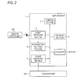
- FIG. 2 is a block diagram showing the hardware configuration of the bar speaker 1.
- the bar speaker 1 is equipped with the light receiving section 2, a control section 3, a storage section 4, an infrared ray emitting section 5, a sound receiving section (sound signal receiving means) 6, and the speakers SP1, SP2, SP3 and SP4.
- the control section 3 executes programs stored in the storage section 4, thereby controlling the operation of the bar speaker 1.
- the storage section 4 stores programs to be executed by the control section 3 and also stores various kinds of necessary data.
- the infrared ray emitting section 5 reemits the infrared ray having the same information as that of the infrared ray transmitted from the remote controller 200 and received through the light receiving section 2.
- the infrared ray emitting section 5 emits the infrared ray of the control signal for changing the sound volume of the television set 100.
- the infrared ray emitting section 5 provided on the rear face of the housing 10, emits the infrared ray, the infrared ray is irradiated toward the television set 100 by a light guide rod described later.
- the sound receiving section 6 receives a sound signal from the television set 100. Upon receiving the sound signal by the sound receiving section 6, sound is emitted forward by the speakers SP1, SP2, SP3 and SP4.
- FIG. 3(A) is a rear view showing the housing 10 of the bar speaker 1
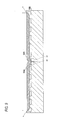
- FIG. 3(B) is a cross-sectional view taken on line II-II of FIG. 3(A)
- FIG. 3(C) is a cross-sectional view taken on line III-III of FIG. 3(A) .
- a concave portion 12 having a rectangular opening being long in the longitudinal direction of the housing 10 of the bar speaker 1 is provided as shown in FIG. 3(A) .
- the concave portion 12 has a bottom face (a face in parallel with the opening) in parallel with the rear face of the housing 10 and has side faces extending along the longitudinal direction of the housing 10.
- the side faces of the concave portion 12 are perpendicular to the bottom face in the vicinity of the bottom face of the concave portion 12 and are expanded in a tapered shape toward the opening in the vicinity of the opening.
- the faces expanded in the tapered shape are referred to as inclined faces 12A.
- the bar speaker 1 is equipped with a light guide rod 20 accommodated in the concave portion 12.
- the light guide rod 20 is, for example, made of an acrylic resin, and is a long light guide member extending along the longitudinal direction of the concave portion 12.
- the infrared ray emitted from the infrared ray emitting section 5 enters from the first end portion (hereafter referred to as the incident-side end portion 201) of the light guide rod 20 in the longitudinal direction thereof.
- the incident infrared ray is guided to the second end portion (hereafter referred to as the outgoing-side end portion 202) in the longitudinal direction.
- the light guide rod 20 has a rectangular shape in cross section in the direction orthogonal to the longitudinal direction of the light guide rod 20 as shown in FIG. 3(C) .
- the cross-sectional shape thereof is not limited to the rectangular shape, but may be, for example, a semicircular shape, a triangular shape or a polygonal shape.
- the height of the convex portion 13 may merely be determined to the extent that the light guide rod 20 placed on the convex portions 13 does not make contact with the bottom face of the concave portion 12, thereby not limited particularly. Furthermore, although the size of the face of each convex portion 13 making contact with the light guide rod 20 is not limited particularly, the size is preferably determined to the extent that the area thereof making contact with the light guide rod 20 can be made as small as possible. Moreover, the number of the convex portions 13 provided on the bottom face of the concave portion 12 can be changed appropriately.
- the infrared ray emitted from the infrared ray emitting section 5 advances from the incident-side end portion toward the outgoing-side end portion of the light guide rod 20 while being totally reflected inside the light guide rod 20.
- the light guide rod 20 is placed on the convex portions 13 as described above, space is formed between the rear face of the light guide rod 20 and the bottom face of the concave portion 12, whereby the contact area between the rear face of the light guide rod 20 and the bottom face of the concave portion 12 is made small.
- This configuration suppresses that the infrared ray is refracted by the contact face between the light guide rod 20 and the concave portion 12 and that the infrared ray is irradiated unexpectedly from the light guide rod 20.
- reflection patterns 21 are provided at a plurality of positions on the rear face (second portion) of the light guide rod 20.
- the rear face of the light guide rod 20 may be surface-treated so as to be formed into an uneven shape.
- the infrared ray advancing while being totally reflected hits the reflection patterns 21, the infrared ray is reflected irregularly and irradiated from the face (hereafter referred to as the side face (first portion)) serving as the face on the opposite side of the above-mentioned rear face of the light guide rod 20 while being expanded radially.
- the portion provided with the reflection patterns 21 functions as a first outgoing portion.
- the infrared ray may irradiated from the side face of the light guide rod 20 by using the light guide rod 20 that is formed by mixing impurities into an acrylic resin or the like.
- the infrared ray irradiated while being expanded from the side face of the light guide rod 20 is not blocked by the side faces of the concave portion 12.
- the infrared ray can be irradiated not only in the normal direction of the rear face of the housing 10 but also in the height direction thereof.
- the light receiving section 102 can receive the infrared ray from the light guide rod 20.
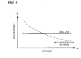
- FIG. 4 is a graph showing the light intensity of the infrared ray irradiated from the side face of the light guide rod 20.
- the horizontal axis represents the distance x from the incident-side end portion in the longitudinal direction
- the vertical axis represents the light intensity S of the infrared ray.
- the dotted line in FIG. 4 indicates the light intensity of the infrared ray at the distance x in the case that the reflection patterns 21 are not formed.
- the signal intensity of the infrared ray incident from the incident-side end portion 201 decreases exponentially in the direction from the incident-side end portion 201 to the outgoing-side end portion 202.
- the light intensity of the infrared ray irradiated from the side face of the light guide rod 20 is preferably constant at all times, regardless of the distance x from the incident-side end portion 201 as indicated by the solid line shown in FIG. 4 .
- M AeBx.
- the light intensity S of the infrared ray irradiated from the side face of the light guide rod 20 is stronger as the density M of the reflection patterns 21 is higher.
- the coefficient A of the above-mentioned expression is made smaller, the density M, that is, the light intensity S, can be made smaller when the distance x is small.
- the coefficient B is made larger, the density M, that is, the light intensity S, can be made larger when the distance x is large.
- the light intensity S can be made constant regardless of the distance x as indicated by the solid line shown in FIG. 4 by adjusting the coefficients A and B depending on the material of the light guide rod 20 or the type of the reflection patterns 21.
- the reflection patterns 21 are not only formed discretely, but in the case that the light guide rod 20 is formed by mixing impurities in an acrylic resin or the like, the concentration of the impurities to be mixed may be changed.
- a reflection pattern 22 is preferably formed uniformly regardless of the above-mentioned expression.
- the infrared ray having entered from the incident-side end portion 201 and having reached the area around the outgoing-side end portion 202 without being reflected by the reflection patterns 21 can be reflected by the reflection pattern 22 and can be irradiated from the side face of the light guide rod 20, whereby the infrared ray having entered from the infrared ray emitting section 5 to the light guide rod 20 can be irradiated from the side face of the light guide rod 20 without any waste.
- the rear face thereof is formed into an inclined face 23 being inclined in a tapered shape toward the side face.
- This inclined face 23 functions as a second outgoing portion for reflecting the infrared ray advancing toward the outgoing-side end portion 202 and for making the infrared ray irradiated to the side face. No reflection pattern is formed on the inclined face 23.
- FIGS. 5(A), 5(B) and 5(C) are views showing the difference in the state in which the infrared ray is irradiated depending on the presence or absence of the inclined face 23. If the inclined face 23 is not provided as shown in FIG. 5(A) , the infrared ray having advanced perpendicularly toward the flat face of the outgoing-side end portion 202 is directly irradiated from the outgoing-side end portion 202. Moreover, since the infrared ray is only reflected by the reflection pattern 22 on the rear face and irradiated in the vicinity of the outgoing-side end portion 202, the infrared ray being irradiated is not expanded beyond the longitudinal width of the light guide rod 20.
- the infrared ray having advanced toward the flat face of the outgoing-side end portion 202 is reflected by the inclined face 23.
- the taper angle ⁇ 1 of the inclined face 23 is set to less than 50 degrees so that the infrared ray having advanced toward the flat face of the outgoing-side end portion 202 is reflected by the side face of the light guide rod 20 (in this example, ⁇ 1 is set to approximately 30 degrees).
- the infrared ray reflected by the inclined face 23 is refracted by the side face of the light guide rod 20 and then irradiated, thereby irradiated while being expanded toward the outgoing-side end portion 202.
- the bar speaker 1 can irradiate the infrared ray in a wide range beyond the longitudinal width of the housing 10 as shown in FIG. 5(C) .
- the bar speaker 1 can send light to the hidden portions.
- the rear face of the light guide rod 20 in the vicinity of the outgoing-side end portion 202 is further inclined in a tapered shape in a direction different from the direction toward the side face.
- the light guide rod 20 is inclined upward in a tapered shape.
- the infrared ray irradiated from the inclined face 23 is irradiated nearly perpendicularly to the side face of the light guide rod 20. Hence, the infrared ray is irradiated only in the normal direction of the rear face of the housing 10.
- the infrared ray having advanced toward the flat face of the outgoing-side end portion 202 in a direction perpendicular thereto is reflected by the face inclined upward and further refracted at the side face of the light guide rod 20 and then irradiated, thereby irradiated while being expanded downward.
- the infrared ray is irradiated not only in the normal direction of the rear face of the housing 10 but also in the height direction thereof.
- the light receiving section 102 can receive the infrared ray from the light guide rod 20.
- the infrared ray having advanced toward the flat face of the outgoing-side end portion 202 in a direction perpendicular thereto is reflected by the face inclined downward and further refracted at the side face of the light guide rod 20 and then irradiated, thereby irradiated while being expanded upward.
- the infrared ray having advanced toward the flat face of the outgoing-side end portion 202 in a direction perpendicular thereto is irradiated while being expanded upward and downward.
- the surface shape of the inclined face 23 may be such a flat face as shown in FIGS. 11(A) and 11(B) or may be such a curved face as shown in FIGS. 11(C) and 11(D) .
- the present invention is not limited to this example in which the inclined face 23 is provided. It may be possible to use a structure in which the infrared ray is refracted in the vicinity of the outgoing-side end portion 202 of the light guide rod 20 and is irradiated while being expanded beyond the longitudinal width of the light guide rod 20.
- the material of the light guide rod is changed at the portion in the vicinity of the outgoing-side end portion 202 of the light guide rod 20 or that an element for refracting the light is additionally provided in the vicinity of the outgoing-side end portion 202 of the light guide rod 20.
- the light from the infrared ray emitting section 5 directly enters from the end portion of the light guide rod 20 in the above-mentioned example, it may be possible that the light enters in the middle of the light guide rod 20 or that the light from the infrared ray emitting section 5 is reflected by a reflecting member and then enter the light guide rod 20.
- FIGS. 8 (A) and 8 (B) are cross-sectional views (corresponding to FIG. 3(A) ) showing a bar speaker
- FIG. 8(B) is an enlarged cross-sectional view showing the bent portion.
- components common to those shown in FIG. 3(B) are designated by the same reference numerals and their descriptions are omitted.
- the incident-side end portion 501 of the light guide rod 50 shown in FIGS. 8 (A) and 8 (B) is bent approximately 90 degrees and formed into a bent portion 51.
- the face of the incident-side end portion 501 is oriented toward the housing 10A of the bar speaker.
- the infrared ray emitting section 5 is installed inside the housing 10A so as to output the infrared ray in a direction in which the rear face of the housing 10A is oriented.
- an inclined flat face 52 is provided on the side face of the light guide rod 50 at the bent portion 51.
- the inclined flat face 52 reflects the infrared ray having been output from the infrared ray emitting section 5 and having entered from the incident-side end portion 501 and then guides the infrared ray in the longitudinal direction.
- the inclination angle ⁇ 2 of the inclined flat face 52 is slightly larger than 45 degrees (for example, by approximately 3 degrees).
- the infrared ray reflected by the inclined flat face 52 advances while being slightly inclined from the longitudinal direction, whereby a more amount of infrared ray is applied to the reflection patterns 21 and the reflection pattern 22, and a more amount of infrared ray is irradiated to the side face of the light guide rod 50.
- the taper angle ⁇ 1 of the inclined face 23 should be set corresponding to the inclination angle ⁇ 2 of the inclined flat face 52.
- the infrared ray emitting section 5 can be provided inside the housing 10A, whereby the infrared ray emitting section 5 does not protrude toward the rear face of the housing 10A, whereby a neat appearance is obtained.
- FIG. 9 is a cross-sectional view (corresponding to FIG. 3(B) ) showing a bar speaker according to application example 1.
- two infrared ray emitting sections 5 are provided at the central portion of a housing 10B.
- a light guide rod 50A and a light guide rod 50B for guiding the infrared rays output from the respective infrared ray emitting sections 5 are installed.
- the light guide rod 50A and the light guide rod 50B have the same configuration and function as those of the light guide rod 50 shown in FIGS. 8 (A) and 8(B) .
- the light guide rod 50A and the light guide rod 50B are installed on the housing 10B in directions different from each other, that is, in directions so that the infrared rays are guided toward the outside of the housing 10B.
- an infrared ray having a constant light intensity is irradiated regardless of the position in the longitudinal direction of the rear face of the housing 10B. Furthermore, the infrared ray can be irradiated in a wide range beyond the longitudinal width of the housing 10B in both the left and right sides of the housing 10B.
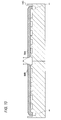
- FIG. 10 is a cross-sectional view (corresponding to FIG. 3(B) ) showing a bar speaker according to application example 2.
- the bar speaker according to application example 2 two infrared ray emitting sections 5 are provided in the vicinity of the left and right end portions of a housing 10C.
- the light guide rod 50A and the light guide rod 50B for guiding the infrared rays output from the respective infrared ray emitting sections 5 are installed.
- the light guide rod 50A and the light guide rod 50B are installed so as to be left-right inverted in comparison with the example shown in FIG. 9 , and also installed on the housing 10C so that the infrared rays are guided toward the inside of the housing 10C.
- an infrared ray having a constant light intensity is irradiated regardless of the position in the longitudinal direction of the rear face of the housing 10C. Furthermore, at the longitudinally central portion of the housing 10C, the infrared ray can be irradiated in the direction in which the rear face of the central portion of the housing 10C is oriented even if the light guide rod 50A and the light guide rod 50B are not installed.
- the range in which light can be irradiated is widened, whereby the light can be guided easily to the position of the light receiving section regardless of the position of the light receiving section on the television set.
Landscapes
- Physics & Mathematics (AREA)
- Engineering & Computer Science (AREA)
- General Physics & Mathematics (AREA)
- Signal Processing (AREA)
- Optics & Photonics (AREA)
- Acoustics & Sound (AREA)
- Health & Medical Sciences (AREA)
- Otolaryngology (AREA)
- Computer Networks & Wireless Communication (AREA)
- Multimedia (AREA)
- Electromagnetism (AREA)
- Optical Couplings Of Light Guides (AREA)
- Light Guides In General And Applications Therefor (AREA)
- Details Of Audible-Bandwidth Transducers (AREA)
- Selective Calling Equipment (AREA)
- Optical Communication System (AREA)
- Planar Illumination Modules (AREA)
Abstract
Description
- The present invention relates to a light guide body for guiding incident light, more particularly, an infrared ray signal, and for irradiating the light from a position different from the incident position of the light.
- In recent years, a speaker is frequently connected to an AV (Audio Visual) apparatus, such as a television set or a player, to reproduce sound with presence even in a general household. As this kind of speaker, what is called a bar speaker that is installed and used in front of a television stand has been proposed (refer to Patent Document 1). The bar speaker has a configuration in which a plurality of speakers are arranged in a housing having a bar shape. However, a light receiving section for receiving the infrared ray signal output from a remote controller is frequently provided at the lower portion of a television set; hence, in the case that the bar speaker is installed, there occurs a problem that the light receiving section is hidden by the bar speaker and the television set cannot receive the infrared ray signal transmitted from the remote controller.
- Accordingly, it is conceived that a relay apparatus for relaying operation signals from the remote controller is interposed between the remote controller and the television set as described, for example, in
Patent Document 2. When the user operates the remote controller and transmits an operation signal, the relay apparatus described inPatent Document 2 transmits the operation signal received from the remote controller to the television set. -
- Patent Document 1:
JP-A-2009-267956 - Patent Document 2:
JP-A-09-275591 - However, the position of the light receiving section of the television set is not the same in all the television sets. Hence, even if such a relay apparatus as described in
Patent Document 2 is installed, the installation position with respect to the width direction of the television set cannot be changed easily, whereby there is a problem that at which position the relay apparatus should be installed. - Accordingly, the present invention is intended to provide a light guide body easily capable of guiding light to a desired position regardless of the position of the light receiving section on the television set.
- A light guide body according to the present invention including a long light guide portion is characterized by comprising: an incident portion which is provided at a first end portion in a longitudinal direction of the light guide portion, and through which light enters; a first outgoing portion which is adapted to irradiate the light guided by the light guide portion from a first portion provided along the longitudinal direction to an outside; and a second outgoing portion which is provided at a second end portion in the longitudinal direction of the light guide portion, and which is adapted to irradiate the light to be guided toward the second end portion to the first portion.
- As described above, with the light guide body according to the present invention, the light entered from the incident portion (the first end portion) is irradiated from the first portion provided along the longitudinal direction of the long light guide portion. Furthermore, with the light guide body according to the present invention, the infrared ray advancing toward the second end portion is also irradiated to the first portion by the second outgoing portion, whereby the infrared ray is irradiated in a wider range. Hence, for example, even in the case that a speaker apparatus is installed in front of the infrared ray receiving section of a television set, if the light guide body is installed so that the longitudinal direction of the light guide portion is aligned with the width direction of the television set, the infrared ray can be made to reach the light receiving section of the television set, regardless of the position of the light receiving section on the television set.
- It is preferable that a second portion of the light guide portion which is provided with the second outgoing portion and located on an opposite side of the first portion should be structured so as to be inclined in a tapered shape toward the first portion. The infrared ray advancing toward the second end portion is reflected by the second portion inclined in the tapered shape and then irradiated to the first portion. Furthermore, the infrared ray can be irradiated in a wide range beyond the longitudinal length of the light guide portion by adjusting the taper angle to less than appropriately 50 degrees.
- Moreover, it is preferable that the second portion should be further inclined in a tapered shape in a direction different from a direction toward the first portion. In this case, the infrared ray can also be irradiated in directions other than the direction perpendicular to the first portion, whereby the infrared ray can be made to reach the light receiving section of the television set even in the case that the light receiving section of the television set is located at a low position.
- Besides, it may be possible that the light guide portion includes a bent portion that is formed by bending the first end portion, and the bent portion is provided with an inclined face on the first portion. With this configuration, the light can be made to enter from the direction perpendicular to the longitudinal direction of the light guide portion, whereby a light emitting section, such as an LED, can be provided inside the housing of an apparatus in which the light guide body is installed. Hence, the light emitting section does not protrude toward the outside of the housing, whereby a neat appearance is obtained.
- Still further, it is preferable that the first outgoing portion should be provided with a reflection portion that is formed so that a density thereof is made higher as going farther from an incident position of the light in the longitudinal direction.
- Since the signal intensity of light becomes weaker as going farther from the incident position of the light, the intensity of the light irradiated from the first portion of the light guide portion can be made uniform in the longitudinal direction by increasing the number of the reflection portions as going away from the incident side.
- The reflection portion may be a portion on which reflection patterns having light-scattering reflectivity are printed or a reflection portion whose flat face is surface-treated so as to be formed into an uneven shape. Alternatively, the reflection portion may be made by mixing impurities in an acrylic resin or the like serving as the material of the light guide portion.
- With the present invention, the range in which light can be irradiated is widened, whereby the light can be guided easily to the position of the light receiving section regardless of the position of the light receiving section on the television set.
-
-
FIGS. 1(A) and 1(B) are views showing an installation state of a speaker apparatus; -
FIG. 2 is a block diagram showing the hardware configuration of the speaker apparatus; -
FIG. 3 (A) is a rear view showing the housing of the bar speaker apparatus,FIG. 3(B) is a cross-sectional view taken on line II-II ofFIG. 3 (A), and FIG. 3 (C) is a cross-sectional view taken on line III-III ofFIG. 3(A) ; -
FIG. 4 is a graph showing the light intensity of the infrared ray irradiated from a light guide rod; -
FIGS. 5(A), 5(B) and 5(C) are views showing the difference in the state in which an infrared ray is irradiated depending on the presence or absence of aninclined face 23; -
FIG. 6 is a view showing a bar speaker and a television set seen from above; -
FIGS. 7(A), 7(B), 7(C) and 7(D) are cross-sectional views showing the state in which an infrared ray is irradiated from theinclined face 23; -
FIGS. 8(A) and FIG. 8(B) are views showing an example of a light guide rod having a bent portion; -
FIG. 9 is a cross-sectional view showing a speaker apparatus according to application example 1; -
FIG. 10 is a cross-sectional view showing a speaker apparatus according to application example 2; and -
FIGS. 11(A), 11(B), 11(C) and 11(D) are cross-sectional views showing examples of theinclined face 23. - A relay apparatus equipped with a light guide body and a speaker apparatus equipped with the relay apparatus according to an embodiment of the present invention will be described below.
- This embodiment provides a bar speaker (speaker apparatus) that is installed and used in front of a television set.
FIG. 1(A) is a perspective view showing abar speaker 1 installed in front of atelevision set 100, andFIG. 1(B) is a side view thereof. - The
bar speaker 1 is installed in front of thetelevision set 100. More specifically, thebar speaker 1 is installed in front of the television stand of thetelevision set 100 so as not to overlap thedisplay screen 101 of the television set 100 in the height direction. - The
television set 100 is equipped with alight receiving section 102 for receiving an infrared ray signal (hereafter referred to as the infrared ray) serving as an operation signal. The infrared ray received by thelight receiving section 102 is transmitted from theremote controller 200 for thetelevision set 100. Thelight receiving section 102 is provided below thedisplay screen 101. In this embodiment, thebar speaker 1 is provided so as to be opposed to the panel on which thelight receiving section 102 is provided. Hence, thelight receiving section 102 cannot directly receive the infrared ray transmitted from the remote controller 300 because the infrared ray is blocked by thebar speaker 1. - The
bar speaker 1 has ahousing 10 having a rectangular parallelepiped shape being long in one direction. Thebar speaker 1 is installed in front of thetelevision set 100 so that the longitudinal direction of thehousing 10 coincides with the width direction of thetelevision set 100 and so that one face (hereafter, this face is referred to as the rear face) of thehousing 10 is located on the side of thetelevision set 100. Thebar speaker 1 is equipped with a plurality of speakers SP1, SP2, SP3 and SP4. The speakers SP1, SP2, SP3 and SP4 are provided along the longitudinal direction of a face (hereafter referred to as the front face) being parallel to the rear face of thehousing 10. Thebar speaker 1 is connected to thetelevision set 100 by wiring, not shown, receives a sound signal from thetelevision set 100, and emits sound from the speakers SP1, SP2, SP3 and SP4 in the forward direction. - The
bar speaker 1 is equipped with alight receiving section 2 for receiving the infrared ray transmitted from theremote controller 200 at the nearly central portion of thehousing 10 in the longitudinal direction thereof on the front face of thehousing 10 and at the lower portion thereof in the height direction. However, the position of thelight receiving section 2 is not limited to the position described in this example, but thelight receiving section 2 may be provided at the upper portion thereof in the height direction. Thebar speaker 1 receives the infrared ray transmitted from theremote controller 200 toward thetelevision set 100 through thelight receiving section 2 as indicated by the dotted line arrow shown inFIG. 1(B) . - Upon receiving the infrared ray through the
light receiving section 2, thebar speaker 1 outputs the received infrared ray from the rear face of thehousing 10 toward thetelevision set 100 as indicated by the solid line arrows shown inFIG. 1(B) . At this time, thebar speaker 1 linearly outputs the infrared ray along the longitudinal direction of thehousing 10. As a result, even in the case that the user has installed thebar speaker 1 without grasping the position of thelight receiving section 102 of thetelevision set 100 in the horizontal direction of thetelevision set 100, thebar speaker 1 can surely make thelight receiving section 102 receive the infrared ray. -
FIG. 2 is a block diagram showing the hardware configuration of thebar speaker 1. Thebar speaker 1 is equipped with thelight receiving section 2, acontrol section 3, astorage section 4, an infraredray emitting section 5, a sound receiving section (sound signal receiving means) 6, and the speakers SP1, SP2, SP3 and SP4. - The
control section 3 executes programs stored in thestorage section 4, thereby controlling the operation of thebar speaker 1. Thestorage section 4 stores programs to be executed by thecontrol section 3 and also stores various kinds of necessary data. - The infrared
ray emitting section 5 reemits the infrared ray having the same information as that of the infrared ray transmitted from theremote controller 200 and received through thelight receiving section 2. For example, in the case that theremote controller 200 emits the infrared ray of the control signal for changing the sound volume of thetelevision set 100 and thebar speaker 1 receives the infrared ray, the infraredray emitting section 5 emits the infrared ray of the control signal for changing the sound volume of thetelevision set 100. When the infraredray emitting section 5, provided on the rear face of thehousing 10, emits the infrared ray, the infrared ray is irradiated toward thetelevision set 100 by a light guide rod described later. - The
sound receiving section 6 receives a sound signal from thetelevision set 100. Upon receiving the sound signal by thesound receiving section 6, sound is emitted forward by the speakers SP1, SP2, SP3 and SP4. -
FIG. 3(A) is a rear view showing thehousing 10 of thebar speaker 1,FIG. 3(B) is a cross-sectional view taken on line II-II ofFIG. 3(A), and FIG. 3(C) is a cross-sectional view taken on line III-III ofFIG. 3(A) . - On the rear face of the
housing 10 of thebar speaker 1, aconcave portion 12 having a rectangular opening being long in the longitudinal direction of thehousing 10 of thebar speaker 1 is provided as shown inFIG. 3(A) . Theconcave portion 12 has a bottom face (a face in parallel with the opening) in parallel with the rear face of thehousing 10 and has side faces extending along the longitudinal direction of thehousing 10. On the bottom face of theconcave portion 12, a plurality ofconvex portions 13 are formed at predetermined intervals along the longitudinal direction of thehousing 10. The side faces of theconcave portion 12 are perpendicular to the bottom face in the vicinity of the bottom face of theconcave portion 12 and are expanded in a tapered shape toward the opening in the vicinity of the opening. The faces expanded in the tapered shape are referred to as inclined faces 12A. - The
bar speaker 1 is equipped with alight guide rod 20 accommodated in theconcave portion 12. Thelight guide rod 20 is, for example, made of an acrylic resin, and is a long light guide member extending along the longitudinal direction of theconcave portion 12. The infrared ray emitted from the infraredray emitting section 5 enters from the first end portion (hereafter referred to as the incident-side end portion 201) of thelight guide rod 20 in the longitudinal direction thereof. The incident infrared ray is guided to the second end portion (hereafter referred to as the outgoing-side end portion 202) in the longitudinal direction. - The
light guide rod 20 has a rectangular shape in cross section in the direction orthogonal to the longitudinal direction of thelight guide rod 20 as shown inFIG. 3(C) . However, the cross-sectional shape thereof is not limited to the rectangular shape, but may be, for example, a semicircular shape, a triangular shape or a polygonal shape. - Since the
light guide rod 20 is placed on theconvex portions 13, space is formed between the rear face of thelight guide rod 20, that is, the face on the side of the bottom face of theconcave portion 12, and the bottom face of theconcave portion 12, as shown inFIG. 3(B) . - The height of the
convex portion 13 may merely be determined to the extent that thelight guide rod 20 placed on theconvex portions 13 does not make contact with the bottom face of theconcave portion 12, thereby not limited particularly. Furthermore, although the size of the face of eachconvex portion 13 making contact with thelight guide rod 20 is not limited particularly, the size is preferably determined to the extent that the area thereof making contact with thelight guide rod 20 can be made as small as possible. Moreover, the number of theconvex portions 13 provided on the bottom face of theconcave portion 12 can be changed appropriately. - The infrared ray emitted from the infrared
ray emitting section 5 advances from the incident-side end portion toward the outgoing-side end portion of thelight guide rod 20 while being totally reflected inside thelight guide rod 20. At this time, since thelight guide rod 20 is placed on theconvex portions 13 as described above, space is formed between the rear face of thelight guide rod 20 and the bottom face of theconcave portion 12, whereby the contact area between the rear face of thelight guide rod 20 and the bottom face of theconcave portion 12 is made small. This configuration suppresses that the infrared ray is refracted by the contact face between thelight guide rod 20 and theconcave portion 12 and that the infrared ray is irradiated unexpectedly from thelight guide rod 20. - In addition,
reflection patterns 21 are provided at a plurality of positions on the rear face (second portion) of thelight guide rod 20. Although it is preferable that thereflection patterns 21 should have light-scattering reflectivity and should be printed, the rear face of thelight guide rod 20 may be surface-treated so as to be formed into an uneven shape. When the infrared ray advancing while being totally reflected hits thereflection patterns 21, the infrared ray is reflected irregularly and irradiated from the face (hereafter referred to as the side face (first portion)) serving as the face on the opposite side of the above-mentioned rear face of thelight guide rod 20 while being expanded radially. Hence, the portion provided with thereflection patterns 21 functions as a first outgoing portion. Furthermore, the infrared ray may irradiated from the side face of thelight guide rod 20 by using thelight guide rod 20 that is formed by mixing impurities into an acrylic resin or the like. - At this time, since the inclined faces 12A are formed in the vicinity of the opening of the
concave portion 12, the infrared ray irradiated while being expanded from the side face of thelight guide rod 20 is not blocked by the side faces of theconcave portion 12. For this reason, in the case that the infrared ray is irradiated radially from thelight guide rod 20, the infrared ray can be irradiated not only in the normal direction of the rear face of thehousing 10 but also in the height direction thereof. Hence, even in the case that thelight guide rod 20 is not opposed to thelight receiving section 102 of thetelevision set 100 and is positioned so as to be deviated away therefrom in the height direction, thelight receiving section 102 can receive the infrared ray from thelight guide rod 20. - The arrangement pattern of the
reflection patterns 21 is determined, for example, as described below.FIG. 4 is a graph showing the light intensity of the infrared ray irradiated from the side face of thelight guide rod 20. InFIG. 4 , the horizontal axis represents the distance x from the incident-side end portion in the longitudinal direction, and the vertical axis represents the light intensity S of the infrared ray. - The dotted line in
FIG. 4 indicates the light intensity of the infrared ray at the distance x in the case that thereflection patterns 21 are not formed. In this case, the signal intensity of the infrared ray incident from the incident-side end portion 201 decreases exponentially in the direction from the incident-side end portion 201 to the outgoing-side end portion 202. In order that the infrared ray can be received surely regardless of the position of thelight receiving section 102 on thetelevision set 100 in the width direction of thetelevision set 100, the light intensity of the infrared ray irradiated from the side face of thelight guide rod 20 is preferably constant at all times, regardless of the distance x from the incident-side end portion 201 as indicated by the solid line shown inFIG. 4 . - Hence, the relationship between the density M of the
reflection patterns 21 and the distance x from the incident-side end portion is assumed to be expressed by an exponential function expression, M = AeBx. The light intensity S of the infrared ray irradiated from the side face of thelight guide rod 20 is stronger as the density M of thereflection patterns 21 is higher. In the case that the coefficient A of the above-mentioned expression is made smaller, the density M, that is, the light intensity S, can be made smaller when the distance x is small. Furthermore, in the case that the coefficient B is made larger, the density M, that is, the light intensity S, can be made larger when the distance x is large. The light intensity S can be made constant regardless of the distance x as indicated by the solid line shown inFIG. 4 by adjusting the coefficients A and B depending on the material of thelight guide rod 20 or the type of thereflection patterns 21. - In order that the intensity of the infrared ray irradiated from the
light guide rod 20 is made constant regardless of the distance x, thereflection patterns 21 are not only formed discretely, but in the case that thelight guide rod 20 is formed by mixing impurities in an acrylic resin or the like, the concentration of the impurities to be mixed may be changed. - Furthermore, in the area around the outgoing-
side end portion 202 of thelight guide rod 20, areflection pattern 22 is preferably formed uniformly regardless of the above-mentioned expression. With this configuration, the infrared ray having entered from the incident-side end portion 201 and having reached the area around the outgoing-side end portion 202 without being reflected by thereflection patterns 21 can be reflected by thereflection pattern 22 and can be irradiated from the side face of thelight guide rod 20, whereby the infrared ray having entered from the infraredray emitting section 5 to thelight guide rod 20 can be irradiated from the side face of thelight guide rod 20 without any waste. - Furthermore, in the vicinity of the outgoing-
side end portion 202 of thelight guide rod 20, the rear face thereof is formed into aninclined face 23 being inclined in a tapered shape toward the side face. Thisinclined face 23 functions as a second outgoing portion for reflecting the infrared ray advancing toward the outgoing-side end portion 202 and for making the infrared ray irradiated to the side face. No reflection pattern is formed on theinclined face 23. -
FIGS. 5(A), 5(B) and 5(C) are views showing the difference in the state in which the infrared ray is irradiated depending on the presence or absence of theinclined face 23. If theinclined face 23 is not provided as shown inFIG. 5(A) , the infrared ray having advanced perpendicularly toward the flat face of the outgoing-side end portion 202 is directly irradiated from the outgoing-side end portion 202. Moreover, since the infrared ray is only reflected by thereflection pattern 22 on the rear face and irradiated in the vicinity of the outgoing-side end portion 202, the infrared ray being irradiated is not expanded beyond the longitudinal width of thelight guide rod 20. - However, in the case that the
inclined face 23 is provided as shown inFIG. 5(B) , the infrared ray having advanced toward the flat face of the outgoing-side end portion 202 is reflected by theinclined face 23. - For example, when it is assumed that the critical angle at which the infrared ray is totally reflected on the boundary face between the
light guide rod 20 and the air is approximately 50 degrees, the taper angle θ1 of theinclined face 23 is set to less than 50 degrees so that the infrared ray having advanced toward the flat face of the outgoing-side end portion 202 is reflected by the side face of the light guide rod 20 (in this example, θ1 is set to approximately 30 degrees). The infrared ray reflected by theinclined face 23 is refracted by the side face of thelight guide rod 20 and then irradiated, thereby irradiated while being expanded toward the outgoing-side end portion 202. Hence, thebar speaker 1 can irradiate the infrared ray in a wide range beyond the longitudinal width of thehousing 10 as shown inFIG. 5(C) . - As a result, as shown in
FIG. 6 , even in the case that the width of thetelevision set 100 is wider than the width of the housing of thebar speaker 1 and thelight receiving section 102 of thetelevision set 100 is hidden by the depth of thehousing 10, thebar speaker 1 can send light to the hidden portions. - On the other hand, as shown in
FIG. 3(C) , the rear face of thelight guide rod 20 in the vicinity of the outgoing-side end portion 202 is further inclined in a tapered shape in a direction different from the direction toward the side face. In other words, as shown inFIG. 3(C) , thelight guide rod 20 is inclined upward in a tapered shape. - If the
inclined face 23 is not inclined upward in a tapered shape as shown inFIG. 7(A) , the infrared ray irradiated from theinclined face 23 is irradiated nearly perpendicularly to the side face of thelight guide rod 20. Hence, the infrared ray is irradiated only in the normal direction of the rear face of thehousing 10. - However, as shown in
FIG. 7(B) , in the case that theinclined face 23 is inclined upward in a tapered shape, the infrared ray having advanced toward the flat face of the outgoing-side end portion 202 in a direction perpendicular thereto is reflected by the face inclined upward and further refracted at the side face of thelight guide rod 20 and then irradiated, thereby irradiated while being expanded downward. As a result, the infrared ray is irradiated not only in the normal direction of the rear face of thehousing 10 but also in the height direction thereof. Hence, even in the case that thelight guide rod 20 is not opposed to thelight receiving section 102 of thetelevision set 100 and is positioned so as to be deviated away therefrom in the height direction, thelight receiving section 102 can receive the infrared ray from thelight guide rod 20. - Furthermore, as shown in
FIG. 7(C) , in the case that theinclined face 23 is inclined downward in a tapered shape, the infrared ray having advanced toward the flat face of the outgoing-side end portion 202 in a direction perpendicular thereto is reflected by the face inclined downward and further refracted at the side face of thelight guide rod 20 and then irradiated, thereby irradiated while being expanded upward. Moreover, as shown inFIG. 7(D) , in the case that theinclined face 23 is inclined upward and downward in a tapered shape, the infrared ray having advanced toward the flat face of the outgoing-side end portion 202 in a direction perpendicular thereto is irradiated while being expanded upward and downward. - The surface shape of the
inclined face 23 may be such a flat face as shown inFIGS. 11(A) and 11(B) or may be such a curved face as shown inFIGS. 11(C) and 11(D) . - Furthermore, although the effect in which the infrared ray is irradiated while being expanded beyond the longitudinal width of the
light guide rod 20 is realized in the above-mentioned example by providing theinclined face 23 in the vicinity of the outgoing-side end portion 202 of thelight guide rod 20, the present invention is not limited to this example in which theinclined face 23 is provided. It may be possible to use a structure in which the infrared ray is refracted in the vicinity of the outgoing-side end portion 202 of thelight guide rod 20 and is irradiated while being expanded beyond the longitudinal width of thelight guide rod 20. For example, it is conceivable that the material of the light guide rod is changed at the portion in the vicinity of the outgoing-side end portion 202 of thelight guide rod 20 or that an element for refracting the light is additionally provided in the vicinity of the outgoing-side end portion 202 of thelight guide rod 20. - Furthermore, although the light from the infrared
ray emitting section 5 directly enters from the end portion of thelight guide rod 20 in the above-mentioned example, it may be possible that the light enters in the middle of thelight guide rod 20 or that the light from the infraredray emitting section 5 is reflected by a reflecting member and then enter thelight guide rod 20. - Moreover, it is possible to use a light guide rod having such a bent portion as shown in
FIGS. 8 (A) and 8 (B). FIG. 8 (A) is a cross-sectional view (corresponding toFIG. 3(A) ) showing a bar speaker, andFIG. 8(B) is an enlarged cross-sectional view showing the bent portion. InFIGS. 8(A) and 8(B) , components common to those shown inFIG. 3(B) are designated by the same reference numerals and their descriptions are omitted. - The incident-
side end portion 501 of thelight guide rod 50 shown inFIGS. 8 (A) and 8 (B) is bent approximately 90 degrees and formed into abent portion 51. Hence, the face of the incident-side end portion 501 is oriented toward thehousing 10A of the bar speaker. In this case, the infraredray emitting section 5 is installed inside thehousing 10A so as to output the infrared ray in a direction in which the rear face of thehousing 10A is oriented. - In addition, an inclined
flat face 52 is provided on the side face of thelight guide rod 50 at thebent portion 51. As shown inFIG. 8(B) , the inclinedflat face 52 reflects the infrared ray having been output from the infraredray emitting section 5 and having entered from the incident-side end portion 501 and then guides the infrared ray in the longitudinal direction. The inclination angle θ2 of the inclinedflat face 52 is slightly larger than 45 degrees (for example, by approximately 3 degrees). Hence, the infrared ray reflected by the inclinedflat face 52 advances while being slightly inclined from the longitudinal direction, whereby a more amount of infrared ray is applied to thereflection patterns 21 and thereflection pattern 22, and a more amount of infrared ray is irradiated to the side face of thelight guide rod 50. - It is preferable that the taper angle θ1 of the
inclined face 23 should be set corresponding to the inclination angle θ2 of the inclinedflat face 52. - With the
light guide rod 50 shown inFIGS. 8 (A) and 8(B) , the infraredray emitting section 5 can be provided inside thehousing 10A, whereby the infraredray emitting section 5 does not protrude toward the rear face of thehousing 10A, whereby a neat appearance is obtained. - Next,
FIG. 9 is a cross-sectional view (corresponding toFIG. 3(B) ) showing a bar speaker according to application example 1. In the bar speaker according to application example 1, two infraredray emitting sections 5 are provided at the central portion of ahousing 10B. Furthermore, alight guide rod 50A and alight guide rod 50B for guiding the infrared rays output from the respective infraredray emitting sections 5 are installed. Thelight guide rod 50A and thelight guide rod 50B have the same configuration and function as those of thelight guide rod 50 shown inFIGS. 8 (A) and 8(B) . Thelight guide rod 50A and thelight guide rod 50B are installed on thehousing 10B in directions different from each other, that is, in directions so that the infrared rays are guided toward the outside of thehousing 10B. - Also in this case, an infrared ray having a constant light intensity is irradiated regardless of the position in the longitudinal direction of the rear face of the
housing 10B. Furthermore, the infrared ray can be irradiated in a wide range beyond the longitudinal width of thehousing 10B in both the left and right sides of thehousing 10B. - Next,
FIG. 10 is a cross-sectional view (corresponding toFIG. 3(B) ) showing a bar speaker according to application example 2. In the bar speaker according to application example 2, two infraredray emitting sections 5 are provided in the vicinity of the left and right end portions of a housing 10C. Furthermore, thelight guide rod 50A and thelight guide rod 50B for guiding the infrared rays output from the respective infraredray emitting sections 5 are installed. However, in this example, thelight guide rod 50A and thelight guide rod 50B are installed so as to be left-right inverted in comparison with the example shown inFIG. 9 , and also installed on the housing 10C so that the infrared rays are guided toward the inside of the housing 10C. - Also in this case, an infrared ray having a constant light intensity is irradiated regardless of the position in the longitudinal direction of the rear face of the housing 10C. Furthermore, at the longitudinally central portion of the housing 10C, the infrared ray can be irradiated in the direction in which the rear face of the central portion of the housing 10C is oriented even if the
light guide rod 50A and thelight guide rod 50B are not installed. - The present application is based on Japanese Patent Application (
JP-A-2012-190485) filed on August 30, 2012 - With the present invention, the range in which light can be irradiated is widened, whereby the light can be guided easily to the position of the light receiving section regardless of the position of the light receiving section on the television set.
-
- 1 ... bar speaker
- 2 ... light receiving section
- 3 ... control section
- 4 ... storage section
- 5 ... infrared ray emitting section
- 6 ... sound receiving section
- SP1, SP2. SP3, SP4 ... speaker
- 10 ... housing
- 12 ... concave portion
- 12A ... inclined face
- 13 ... convex portion
- 20 ... light guide rod
- 21, 22 ... reflection pattern
- 23 ... inclined face
- 100 ... television set
- 101 ... display screen
- 102 ... light receiving section
- 200 ... remote controller
- 201 ... incident-side end portion
- 202 ... outgoing-side end portion
- 300 ... remote controller
Claims (7)
- A light guide body including a long light guide portion, the light guide body characterized by comprising:an incident portion which is provided at a first end portion in a longitudinal direction of the light guide portion, and through which light enters;a first outgoing portion which is adapted to irradiate the light guided by the light guide portion from a first portion provided along the longitudinal direction to an outside; anda second outgoing portion which is provided at a second end portion in the longitudinal direction of the light guide portion, and which is adapted to irradiate the light to be guided toward the second end portion to the first portion.
- The light guide body according to claim 1, characterized in that a second portion of the light guide portion which is provided with the second outgoing portion and located on an opposite side of the first portion is inclined in a tapered shape toward the first portion.
- The light guide body according to claim 2, characterized in that the second portion which is located on the opposite side of the first portion is further inclined in a tapered shape in a direction different from a direction toward the first portion.
- The light guide body according to any one of claims 1 to 3, characterized in that
the light guide portion includes a bent portion that is formed by bending the first end portion, and
the bent portion is provided with an inclined face on the first portion. - The light guide body according to any one of claims 1 to 4, characterized in that the first outgoing portion is provided with a reflection portion that is formed so that a density thereof is made higher as going farther from an incident position of the light in the longitudinal direction.
- A relay apparatus characterized by comprising:a housing;light signal receiving means, provided on a first face of the housing, for receiving a light signal from an outside; andlight emitting means for emitting light depending on the light signal received by the light signal receiving means, whereinthe light guide body according to any one of claims 1 to 5 is provided on a second face different from the first face of the housing, andthe light emitted by the light emitting means enters the incident portion.
- A speaker apparatus characterized by comprising:the relay apparatus according to claim 6;sound signal receiving means for receiving a sound signal from an outside, andsound outputting means for outputting the sound signal received by the sound signal receiving means as sound.
Applications Claiming Priority (2)
| Application Number | Priority Date | Filing Date | Title |
|---|---|---|---|
| JP2012190485A JP5831404B2 (en) | 2012-08-30 | 2012-08-30 | Relay device and speaker device |
| PCT/JP2013/072027 WO2014034447A1 (en) | 2012-08-30 | 2013-08-16 | Light guide element, relay device, and speaker device |
Publications (3)
| Publication Number | Publication Date |
|---|---|
| EP2891910A1 true EP2891910A1 (en) | 2015-07-08 |
| EP2891910A4 EP2891910A4 (en) | 2016-05-25 |
| EP2891910B1 EP2891910B1 (en) | 2018-11-14 |
Family
ID=50183262
Family Applications (1)
| Application Number | Title | Priority Date | Filing Date |
|---|---|---|---|
| EP13833825.6A Not-in-force EP2891910B1 (en) | 2012-08-30 | 2013-08-16 | Light guide element, relay device, and speaker device |
Country Status (5)
| Country | Link |
|---|---|
| US (1) | US9435926B2 (en) |
| EP (1) | EP2891910B1 (en) |
| JP (1) | JP5831404B2 (en) |
| CN (1) | CN104603651B (en) |
| WO (1) | WO2014034447A1 (en) |
Families Citing this family (9)
| Publication number | Priority date | Publication date | Assignee | Title |
|---|---|---|---|---|
| US9866961B2 (en) * | 2004-12-01 | 2018-01-09 | Todd Beauchamp | Multi-channel loudspeaker enclosure with laterally projecting wings and method for orienting and driving multiple loudspeakers |
| US9820024B1 (en) | 2014-05-31 | 2017-11-14 | Glori, Llc | Wireless speaker and lamp |
| CN106704876B (en) * | 2016-12-13 | 2019-09-17 | 三明学院 | A kind of production of flashlight and its application method |
| US10337705B2 (en) | 2017-06-07 | 2019-07-02 | Glori, Llc | Lamp for supporting a speaker assembly or inductive charger |
| JP6936660B2 (en) * | 2017-08-25 | 2021-09-22 | シャープ株式会社 | Display device |
| US10880009B2 (en) | 2019-05-24 | 2020-12-29 | Sonos, Inc. | Control signal repeater system |
| CN210839894U (en) * | 2019-12-30 | 2020-06-23 | 深圳Tcl数字技术有限公司 | A far-field voice stand with lens function and electrical equipment |
| JP7177803B2 (en) * | 2020-07-08 | 2022-11-24 | シャープ株式会社 | Display device |
| US12515544B2 (en) * | 2021-07-30 | 2026-01-06 | Eaton Intelligent Power Limited | Light pipe apparatus and associated electronic device |
Family Cites Families (22)
| Publication number | Priority date | Publication date | Assignee | Title |
|---|---|---|---|---|
| JPH08256387A (en) * | 1995-03-17 | 1996-10-01 | Miyuu:Kk | Repeater for wireless remote controller |
| JPH09325221A (en) * | 1996-04-04 | 1997-12-16 | Hitachi Cable Ltd | Lighting equipment |
| JPH09275591A (en) | 1996-04-08 | 1997-10-21 | Sony Corp | Remote control system |
| JP3921915B2 (en) * | 2000-03-22 | 2007-05-30 | 松下電器産業株式会社 | Display device |
| JP2005114894A (en) * | 2003-10-06 | 2005-04-28 | Konica Minolta Business Technologies Inc | Linear lighting device |
| JP2007006057A (en) * | 2005-06-23 | 2007-01-11 | Yamaha Corp | Sound signal amplifier |
| US8310373B2 (en) * | 2005-10-19 | 2012-11-13 | Schweitzer Engineering Laboratories, Inc. | System, a tool and a method for communicating with a faulted circuit indicator using a display |
| JP2007183470A (en) * | 2006-01-10 | 2007-07-19 | Rohm Co Ltd | Light guide member |
| JP4887907B2 (en) * | 2006-05-26 | 2012-02-29 | コニカミノルタホールディングス株式会社 | Video display device |
| JP2007324734A (en) * | 2006-05-30 | 2007-12-13 | Funai Electric Co Ltd | Remote control device, control device, and control system |
| TWI323090B (en) * | 2006-07-28 | 2010-04-01 | Au Optronics Corp | Electronic devices having reflecting portions to reflect optical signals to receiving portions thereof |
| JP2009032558A (en) * | 2007-07-27 | 2009-02-12 | Casio Hitachi Mobile Communications Co Ltd | Light guide structure |
| TWI351830B (en) * | 2007-11-30 | 2011-11-01 | Amtran Technology Co Ltd | Remote controlling system using optical fiber |
| JP2009267956A (en) | 2008-04-28 | 2009-11-12 | Sony Corp | Audio output system, and audio output method |
| JP4596039B2 (en) * | 2008-05-15 | 2010-12-08 | ソニー株式会社 | Electronics |
| US8342731B2 (en) * | 2008-10-01 | 2013-01-01 | Sharp Kabushiki Kaisha | Lighting device, display device and television receiver |
| WO2010064473A1 (en) * | 2008-12-05 | 2010-06-10 | シャープ株式会社 | Illumination device, display device, and television reception device |
| JP2010282869A (en) * | 2009-06-05 | 2010-12-16 | Colcoat Kk | Line lighting device |
| JP5696584B2 (en) * | 2011-05-20 | 2015-04-08 | ヤマハ株式会社 | Relay device and speaker device |
| US9081125B2 (en) * | 2011-08-08 | 2015-07-14 | Quarkstar Llc | Illumination devices including multiple light emitting elements |
| US9223080B2 (en) * | 2012-04-24 | 2015-12-29 | Qualcomm Mems Technologies, Inc. | Light guide with narrow angle light output and methods |
| EP3081846B1 (en) * | 2013-07-18 | 2018-03-28 | Quarkstar LLC | Illumination device in which source light injection is non-parallel to device's optical axis |
-
2012
- 2012-08-30 JP JP2012190485A patent/JP5831404B2/en active Active
-
2013
- 2013-08-16 EP EP13833825.6A patent/EP2891910B1/en not_active Not-in-force
- 2013-08-16 WO PCT/JP2013/072027 patent/WO2014034447A1/en not_active Ceased
- 2013-08-16 US US14/424,465 patent/US9435926B2/en active Active
- 2013-08-16 CN CN201380045499.1A patent/CN104603651B/en active Active
Also Published As
| Publication number | Publication date |
|---|---|
| US20150212248A1 (en) | 2015-07-30 |
| CN104603651A (en) | 2015-05-06 |
| US9435926B2 (en) | 2016-09-06 |
| JP5831404B2 (en) | 2015-12-09 |
| EP2891910A4 (en) | 2016-05-25 |
| WO2014034447A1 (en) | 2014-03-06 |
| CN104603651B (en) | 2018-04-10 |
| EP2891910B1 (en) | 2018-11-14 |
| JP2014048415A (en) | 2014-03-17 |
Similar Documents
| Publication | Publication Date | Title |
|---|---|---|
| US9435926B2 (en) | Light guide body, relay apparatus, and speaker apparatus | |
| US11112107B2 (en) | Display apparatus | |
| JP5696584B2 (en) | Relay device and speaker device | |
| CN110337384B (en) | Lighting device for interior trim | |
| US20140105560A1 (en) | Light Guide Body | |
| EP2372415B1 (en) | Display device | |
| JP2005129409A (en) | Backlight device | |
| JP5218608B2 (en) | Light guide | |
| KR20120017585A (en) | Touch screen panel | |
| US8613539B2 (en) | Computer bezel with light-guide structure | |
| JP2007250489A (en) | Backlight device for liquid crystal display device | |
| US20130058127A1 (en) | Computer bezel with light-guide structure | |
| JP5857270B2 (en) | Illuminated vanity | |
| US8827524B2 (en) | Computer bezel with light-guide structure | |
| JP4642811B2 (en) | Equipment with optical display | |
| JP2009042364A (en) | Still image display device | |
| JPH05290607A (en) | Display lamp cover | |
| JP6733317B2 (en) | Window lighting equipment | |
| TW201503612A (en) | Optical signal transmission device | |
| JP2011200319A (en) | Board mounting structure and game machine | |
| US20130070473A1 (en) | Computer bezel with light-guide structure | |
| JP5101555B2 (en) | Electronics | |
| JP3111700U (en) | LED light emitting device | |
| US10532694B2 (en) | Lighting apparatus for an interior trim piece of a motor vehicle | |
| KR20190043909A (en) | Display apparatus |
Legal Events
| Date | Code | Title | Description |
|---|---|---|---|
| PUAI | Public reference made under article 153(3) epc to a published international application that has entered the european phase |
Free format text: ORIGINAL CODE: 0009012 |
|
| 17P | Request for examination filed |
Effective date: 20150225 |
|
| AK | Designated contracting states |
Kind code of ref document: A1 Designated state(s): AL AT BE BG CH CY CZ DE DK EE ES FI FR GB GR HR HU IE IS IT LI LT LU LV MC MK MT NL NO PL PT RO RS SE SI SK SM TR |
|
| AX | Request for extension of the european patent |
Extension state: BA ME |
|
| DAX | Request for extension of the european patent (deleted) | ||
| RA4 | Supplementary search report drawn up and despatched (corrected) |
Effective date: 20160422 |
|
| RIC1 | Information provided on ipc code assigned before grant |
Ipc: H04Q 9/00 20060101ALI20160418BHEP Ipc: H04R 1/02 20060101ALI20160418BHEP Ipc: G02B 6/00 20060101AFI20160418BHEP Ipc: F21V 8/00 20060101ALI20160418BHEP Ipc: H04B 10/29 20130101ALI20160418BHEP Ipc: G08C 23/04 20060101ALI20160418BHEP Ipc: H04N 5/00 20110101ALI20160418BHEP |
|
| RIN1 | Information on inventor provided before grant (corrected) |
Inventor name: SUZUKI, KOJI Inventor name: KAWAIDA, YOSHIAKI Inventor name: YAMAMOTO, MASAKI |
|
| RIC1 | Information provided on ipc code assigned before grant |
Ipc: H04N 5/00 20110101ALI20180322BHEP Ipc: F21V 8/00 20060101ALI20180322BHEP Ipc: G08C 23/04 20060101ALI20180322BHEP Ipc: H04R 1/02 20060101ALI20180322BHEP Ipc: G02B 6/10 20060101ALI20180322BHEP Ipc: G02B 6/00 20060101AFI20180322BHEP Ipc: H04B 10/29 20130101ALI20180322BHEP Ipc: H04Q 9/00 20060101ALI20180322BHEP |
|
| GRAP | Despatch of communication of intention to grant a patent |
Free format text: ORIGINAL CODE: EPIDOSNIGR1 |
|
| STAA | Information on the status of an ep patent application or granted ep patent |
Free format text: STATUS: GRANT OF PATENT IS INTENDED |
|
| INTG | Intention to grant announced |
Effective date: 20180525 |
|
| GRAS | Grant fee paid |
Free format text: ORIGINAL CODE: EPIDOSNIGR3 |
|
| GRAA | (expected) grant |
Free format text: ORIGINAL CODE: 0009210 |
|
| STAA | Information on the status of an ep patent application or granted ep patent |
Free format text: STATUS: THE PATENT HAS BEEN GRANTED |
|
| AK | Designated contracting states |
Kind code of ref document: B1 Designated state(s): AL AT BE BG CH CY CZ DE DK EE ES FI FR GB GR HR HU IE IS IT LI LT LU LV MC MK MT NL NO PL PT RO RS SE SI SK SM TR |
|
| REG | Reference to a national code |
Ref country code: CH Ref legal event code: EP Ref country code: AT Ref legal event code: REF Ref document number: 1065497 Country of ref document: AT Kind code of ref document: T Effective date: 20181115 |
|
| REG | Reference to a national code |
Ref country code: DE Ref legal event code: R096 Ref document number: 602013046856 Country of ref document: DE |
|
| REG | Reference to a national code |
Ref country code: IE Ref legal event code: FG4D |
|
| REG | Reference to a national code |
Ref country code: NL Ref legal event code: MP Effective date: 20181114 |
|
| REG | Reference to a national code |
Ref country code: LT Ref legal event code: MG4D |
|
| REG | Reference to a national code |
Ref country code: AT Ref legal event code: MK05 Ref document number: 1065497 Country of ref document: AT Kind code of ref document: T Effective date: 20181114 |
|
| PG25 | Lapsed in a contracting state [announced via postgrant information from national office to epo] |
Ref country code: AT Free format text: LAPSE BECAUSE OF FAILURE TO SUBMIT A TRANSLATION OF THE DESCRIPTION OR TO PAY THE FEE WITHIN THE PRESCRIBED TIME-LIMIT Effective date: 20181114 Ref country code: HR Free format text: LAPSE BECAUSE OF FAILURE TO SUBMIT A TRANSLATION OF THE DESCRIPTION OR TO PAY THE FEE WITHIN THE PRESCRIBED TIME-LIMIT Effective date: 20181114 Ref country code: NO Free format text: LAPSE BECAUSE OF FAILURE TO SUBMIT A TRANSLATION OF THE DESCRIPTION OR TO PAY THE FEE WITHIN THE PRESCRIBED TIME-LIMIT Effective date: 20190214 Ref country code: LV Free format text: LAPSE BECAUSE OF FAILURE TO SUBMIT A TRANSLATION OF THE DESCRIPTION OR TO PAY THE FEE WITHIN THE PRESCRIBED TIME-LIMIT Effective date: 20181114 Ref country code: FI Free format text: LAPSE BECAUSE OF FAILURE TO SUBMIT A TRANSLATION OF THE DESCRIPTION OR TO PAY THE FEE WITHIN THE PRESCRIBED TIME-LIMIT Effective date: 20181114 Ref country code: IS Free format text: LAPSE BECAUSE OF FAILURE TO SUBMIT A TRANSLATION OF THE DESCRIPTION OR TO PAY THE FEE WITHIN THE PRESCRIBED TIME-LIMIT Effective date: 20190314 Ref country code: BG Free format text: LAPSE BECAUSE OF FAILURE TO SUBMIT A TRANSLATION OF THE DESCRIPTION OR TO PAY THE FEE WITHIN THE PRESCRIBED TIME-LIMIT Effective date: 20190214 Ref country code: LT Free format text: LAPSE BECAUSE OF FAILURE TO SUBMIT A TRANSLATION OF THE DESCRIPTION OR TO PAY THE FEE WITHIN THE PRESCRIBED TIME-LIMIT Effective date: 20181114 Ref country code: ES Free format text: LAPSE BECAUSE OF FAILURE TO SUBMIT A TRANSLATION OF THE DESCRIPTION OR TO PAY THE FEE WITHIN THE PRESCRIBED TIME-LIMIT Effective date: 20181114 |
|
| PG25 | Lapsed in a contracting state [announced via postgrant information from national office to epo] |
Ref country code: GR Free format text: LAPSE BECAUSE OF FAILURE TO SUBMIT A TRANSLATION OF THE DESCRIPTION OR TO PAY THE FEE WITHIN THE PRESCRIBED TIME-LIMIT Effective date: 20190215 Ref country code: NL Free format text: LAPSE BECAUSE OF FAILURE TO SUBMIT A TRANSLATION OF THE DESCRIPTION OR TO PAY THE FEE WITHIN THE PRESCRIBED TIME-LIMIT Effective date: 20181114 Ref country code: AL Free format text: LAPSE BECAUSE OF FAILURE TO SUBMIT A TRANSLATION OF THE DESCRIPTION OR TO PAY THE FEE WITHIN THE PRESCRIBED TIME-LIMIT Effective date: 20181114 Ref country code: PT Free format text: LAPSE BECAUSE OF FAILURE TO SUBMIT A TRANSLATION OF THE DESCRIPTION OR TO PAY THE FEE WITHIN THE PRESCRIBED TIME-LIMIT Effective date: 20190314 Ref country code: SE Free format text: LAPSE BECAUSE OF FAILURE TO SUBMIT A TRANSLATION OF THE DESCRIPTION OR TO PAY THE FEE WITHIN THE PRESCRIBED TIME-LIMIT Effective date: 20181114 Ref country code: RS Free format text: LAPSE BECAUSE OF FAILURE TO SUBMIT A TRANSLATION OF THE DESCRIPTION OR TO PAY THE FEE WITHIN THE PRESCRIBED TIME-LIMIT Effective date: 20181114 |
|
| PG25 | Lapsed in a contracting state [announced via postgrant information from national office to epo] |
Ref country code: PL Free format text: LAPSE BECAUSE OF FAILURE TO SUBMIT A TRANSLATION OF THE DESCRIPTION OR TO PAY THE FEE WITHIN THE PRESCRIBED TIME-LIMIT Effective date: 20181114 Ref country code: CZ Free format text: LAPSE BECAUSE OF FAILURE TO SUBMIT A TRANSLATION OF THE DESCRIPTION OR TO PAY THE FEE WITHIN THE PRESCRIBED TIME-LIMIT Effective date: 20181114 Ref country code: IT Free format text: LAPSE BECAUSE OF FAILURE TO SUBMIT A TRANSLATION OF THE DESCRIPTION OR TO PAY THE FEE WITHIN THE PRESCRIBED TIME-LIMIT Effective date: 20181114 Ref country code: DK Free format text: LAPSE BECAUSE OF FAILURE TO SUBMIT A TRANSLATION OF THE DESCRIPTION OR TO PAY THE FEE WITHIN THE PRESCRIBED TIME-LIMIT Effective date: 20181114 |
|
| REG | Reference to a national code |
Ref country code: DE Ref legal event code: R097 Ref document number: 602013046856 Country of ref document: DE |
|
| PG25 | Lapsed in a contracting state [announced via postgrant information from national office to epo] |
Ref country code: RO Free format text: LAPSE BECAUSE OF FAILURE TO SUBMIT A TRANSLATION OF THE DESCRIPTION OR TO PAY THE FEE WITHIN THE PRESCRIBED TIME-LIMIT Effective date: 20181114 Ref country code: SK Free format text: LAPSE BECAUSE OF FAILURE TO SUBMIT A TRANSLATION OF THE DESCRIPTION OR TO PAY THE FEE WITHIN THE PRESCRIBED TIME-LIMIT Effective date: 20181114 Ref country code: EE Free format text: LAPSE BECAUSE OF FAILURE TO SUBMIT A TRANSLATION OF THE DESCRIPTION OR TO PAY THE FEE WITHIN THE PRESCRIBED TIME-LIMIT Effective date: 20181114 Ref country code: SM Free format text: LAPSE BECAUSE OF FAILURE TO SUBMIT A TRANSLATION OF THE DESCRIPTION OR TO PAY THE FEE WITHIN THE PRESCRIBED TIME-LIMIT Effective date: 20181114 |
|
| PLBE | No opposition filed within time limit |
Free format text: ORIGINAL CODE: 0009261 |
|
| STAA | Information on the status of an ep patent application or granted ep patent |
Free format text: STATUS: NO OPPOSITION FILED WITHIN TIME LIMIT |
|
| 26N | No opposition filed |
Effective date: 20190815 |
|
| PG25 | Lapsed in a contracting state [announced via postgrant information from national office to epo] |
Ref country code: SI Free format text: LAPSE BECAUSE OF FAILURE TO SUBMIT A TRANSLATION OF THE DESCRIPTION OR TO PAY THE FEE WITHIN THE PRESCRIBED TIME-LIMIT Effective date: 20181114 |
|
| PG25 | Lapsed in a contracting state [announced via postgrant information from national office to epo] |
Ref country code: TR Free format text: LAPSE BECAUSE OF FAILURE TO SUBMIT A TRANSLATION OF THE DESCRIPTION OR TO PAY THE FEE WITHIN THE PRESCRIBED TIME-LIMIT Effective date: 20181114 |
|
| GBPC | Gb: european patent ceased through non-payment of renewal fee |
Effective date: 20190816 |
|
| PG25 | Lapsed in a contracting state [announced via postgrant information from national office to epo] |
Ref country code: MC Free format text: LAPSE BECAUSE OF FAILURE TO SUBMIT A TRANSLATION OF THE DESCRIPTION OR TO PAY THE FEE WITHIN THE PRESCRIBED TIME-LIMIT Effective date: 20181114 Ref country code: LU Free format text: LAPSE BECAUSE OF NON-PAYMENT OF DUE FEES Effective date: 20190816 Ref country code: CH Free format text: LAPSE BECAUSE OF NON-PAYMENT OF DUE FEES Effective date: 20190831 Ref country code: LI Free format text: LAPSE BECAUSE OF NON-PAYMENT OF DUE FEES Effective date: 20190831 |
|
| REG | Reference to a national code |
Ref country code: BE Ref legal event code: MM Effective date: 20190831 |
|
| PG25 | Lapsed in a contracting state [announced via postgrant information from national office to epo] |
Ref country code: IE Free format text: LAPSE BECAUSE OF NON-PAYMENT OF DUE FEES Effective date: 20190816 Ref country code: FR Free format text: LAPSE BECAUSE OF NON-PAYMENT OF DUE FEES Effective date: 20190831 |
|
| PG25 | Lapsed in a contracting state [announced via postgrant information from national office to epo] |
Ref country code: GB Free format text: LAPSE BECAUSE OF NON-PAYMENT OF DUE FEES Effective date: 20190816 Ref country code: BE Free format text: LAPSE BECAUSE OF NON-PAYMENT OF DUE FEES Effective date: 20190831 |
|
| PG25 | Lapsed in a contracting state [announced via postgrant information from national office to epo] |
Ref country code: CY Free format text: LAPSE BECAUSE OF FAILURE TO SUBMIT A TRANSLATION OF THE DESCRIPTION OR TO PAY THE FEE WITHIN THE PRESCRIBED TIME-LIMIT Effective date: 20181114 |
|
| PG25 | Lapsed in a contracting state [announced via postgrant information from national office to epo] |
Ref country code: MT Free format text: LAPSE BECAUSE OF FAILURE TO SUBMIT A TRANSLATION OF THE DESCRIPTION OR TO PAY THE FEE WITHIN THE PRESCRIBED TIME-LIMIT Effective date: 20181114 Ref country code: HU Free format text: LAPSE BECAUSE OF FAILURE TO SUBMIT A TRANSLATION OF THE DESCRIPTION OR TO PAY THE FEE WITHIN THE PRESCRIBED TIME-LIMIT; INVALID AB INITIO Effective date: 20130816 |
|
| PG25 | Lapsed in a contracting state [announced via postgrant information from national office to epo] |
Ref country code: MK Free format text: LAPSE BECAUSE OF FAILURE TO SUBMIT A TRANSLATION OF THE DESCRIPTION OR TO PAY THE FEE WITHIN THE PRESCRIBED TIME-LIMIT Effective date: 20181114 |
|
| PGFP | Annual fee paid to national office [announced via postgrant information from national office to epo] |
Ref country code: DE Payment date: 20240821 Year of fee payment: 12 |
|
| REG | Reference to a national code |
Ref country code: DE Ref legal event code: R119 Ref document number: 602013046856 Country of ref document: DE |