EP2891859A1 - Method for heating a metal material in an industrial furnace - Google Patents
Method for heating a metal material in an industrial furnace Download PDFInfo
- Publication number
- EP2891859A1 EP2891859A1 EP14003680.7A EP14003680A EP2891859A1 EP 2891859 A1 EP2891859 A1 EP 2891859A1 EP 14003680 A EP14003680 A EP 14003680A EP 2891859 A1 EP2891859 A1 EP 2891859A1
- Authority
- EP
- European Patent Office
- Prior art keywords
- oxidant
- zone
- metal material
- oxygen
- dark zone
- Prior art date
- Legal status (The legal status is an assumption and is not a legal conclusion. Google has not performed a legal analysis and makes no representation as to the accuracy of the status listed.)
- Withdrawn
Links
- 238000010438 heat treatment Methods 0.000 title claims abstract description 56
- 239000007769 metal material Substances 0.000 title claims abstract description 49
- 238000000034 method Methods 0.000 title claims abstract description 24
- 239000007800 oxidant agent Substances 0.000 claims abstract description 62
- 230000001590 oxidative effect Effects 0.000 claims abstract description 61
- 239000001301 oxygen Substances 0.000 claims abstract description 55
- 229910052760 oxygen Inorganic materials 0.000 claims abstract description 55
- 238000002485 combustion reaction Methods 0.000 claims abstract description 34
- QVGXLLKOCUKJST-UHFFFAOYSA-N atomic oxygen Chemical compound [O] QVGXLLKOCUKJST-UHFFFAOYSA-N 0.000 claims abstract description 32
- 239000000446 fuel Substances 0.000 claims abstract description 23
- 239000007789 gas Substances 0.000 claims abstract description 20
- 239000000567 combustion gas Substances 0.000 claims abstract description 12
- 230000003247 decreasing effect Effects 0.000 claims description 13
- 238000011144 upstream manufacturing Methods 0.000 claims description 9
- 230000007423 decrease Effects 0.000 claims description 6
- UGFAIRIUMAVXCW-UHFFFAOYSA-N Carbon monoxide Chemical compound [O+]#[C-] UGFAIRIUMAVXCW-UHFFFAOYSA-N 0.000 claims description 4
- 239000003546 flue gas Substances 0.000 claims description 4
- 239000000203 mixture Substances 0.000 description 8
- IJGRMHOSHXDMSA-UHFFFAOYSA-N Atomic nitrogen Chemical compound N#N IJGRMHOSHXDMSA-UHFFFAOYSA-N 0.000 description 6
- 238000013021 overheating Methods 0.000 description 6
- CURLTUGMZLYLDI-UHFFFAOYSA-N Carbon dioxide Chemical compound O=C=O CURLTUGMZLYLDI-UHFFFAOYSA-N 0.000 description 5
- 239000000463 material Substances 0.000 description 5
- 229910000831 Steel Inorganic materials 0.000 description 4
- 229910002092 carbon dioxide Inorganic materials 0.000 description 4
- VNWKTOKETHGBQD-UHFFFAOYSA-N methane Chemical compound C VNWKTOKETHGBQD-UHFFFAOYSA-N 0.000 description 4
- 239000010959 steel Substances 0.000 description 4
- 229910001868 water Inorganic materials 0.000 description 4
- 239000002184 metal Substances 0.000 description 3
- 229910052757 nitrogen Inorganic materials 0.000 description 3
- 239000003345 natural gas Substances 0.000 description 2
- MYMOFIZGZYHOMD-UHFFFAOYSA-N Dioxygen Chemical compound O=O MYMOFIZGZYHOMD-UHFFFAOYSA-N 0.000 description 1
- 230000015572 biosynthetic process Effects 0.000 description 1
- 239000001569 carbon dioxide Substances 0.000 description 1
- 230000006735 deficit Effects 0.000 description 1
- 239000002737 fuel gas Substances 0.000 description 1
- 239000007788 liquid Substances 0.000 description 1
- 238000004519 manufacturing process Methods 0.000 description 1
- 238000012986 modification Methods 0.000 description 1
- 230000004048 modification Effects 0.000 description 1
- 239000007787 solid Substances 0.000 description 1
- 229910001220 stainless steel Inorganic materials 0.000 description 1
- 239000010935 stainless steel Substances 0.000 description 1
- 230000001502 supplementing effect Effects 0.000 description 1
- XLYOFNOQVPJJNP-UHFFFAOYSA-N water Substances O XLYOFNOQVPJJNP-UHFFFAOYSA-N 0.000 description 1
Images

Classifications
-
- F—MECHANICAL ENGINEERING; LIGHTING; HEATING; WEAPONS; BLASTING
- F27—FURNACES; KILNS; OVENS; RETORTS
- F27D—DETAILS OR ACCESSORIES OF FURNACES, KILNS, OVENS OR RETORTS, IN SO FAR AS THEY ARE OF KINDS OCCURRING IN MORE THAN ONE KIND OF FURNACE
- F27D99/00—Subject matter not provided for in other groups of this subclass
- F27D99/0001—Heating elements or systems
- F27D99/0033—Heating elements or systems using burners
-
- F—MECHANICAL ENGINEERING; LIGHTING; HEATING; WEAPONS; BLASTING
- F27—FURNACES; KILNS; OVENS; RETORTS
- F27B—FURNACES, KILNS, OVENS OR RETORTS IN GENERAL; OPEN SINTERING OR LIKE APPARATUS
- F27B9/00—Furnaces through which the charge is moved mechanically, e.g. of tunnel type; Similar furnaces in which the charge moves by gravity
- F27B9/14—Furnaces through which the charge is moved mechanically, e.g. of tunnel type; Similar furnaces in which the charge moves by gravity characterised by the path of the charge during treatment; characterised by the means by which the charge is moved during treatment
- F27B9/20—Furnaces through which the charge is moved mechanically, e.g. of tunnel type; Similar furnaces in which the charge moves by gravity characterised by the path of the charge during treatment; characterised by the means by which the charge is moved during treatment the charge moving in a substantially straight path
-
- F—MECHANICAL ENGINEERING; LIGHTING; HEATING; WEAPONS; BLASTING
- F27—FURNACES; KILNS; OVENS; RETORTS
- F27B—FURNACES, KILNS, OVENS OR RETORTS IN GENERAL; OPEN SINTERING OR LIKE APPARATUS
- F27B9/00—Furnaces through which the charge is moved mechanically, e.g. of tunnel type; Similar furnaces in which the charge moves by gravity
- F27B9/30—Details, accessories or equipment specially adapted for furnaces of these types
- F27B9/36—Arrangements of heating devices
Definitions
- the present invention relates to a method for heating metal material in an industrial furnace.
- the invention also relates to a method for upgrading an air burner heated industrial furnace in order to increase the combustion efficiency.
- Metal materials such as slabs, billets and blooms, are conventionally heated in industrial furnaces which are heated using air burners, where combustion of a fuel takes place with air supplied by the burner.
- air burners where combustion of a fuel takes place with air supplied by the burner.
- the combustion products flow upstream in relation to the transport direction of the metal material, thereby heating the material which is approaching the air burners.
- dark zone in which loaded metal material is pre-heated by the counter-currently flowing combustion gases before entering the heating zone or zones of the furnace.
- a problem is that air combustion is inefficient, since large volumes of nitrogen are heated in the process. It is therefore desirable to use high-oxygen oxidants to replace air in the above described furnaces.
- the present invention solves the above described problems.
- the invention relates to a method for heating a metal material in an industrial furnace comprising a dark zone and at least one heating zone arranged downstream of the dark zone, which heating zone is heated using at least one burner, wherein said metal material is transported through the dark zone and thereafter through the heating zone, and wherein combustion gases circulate counter-currently through the industrial furnace through the at least one heating zone and thereafter through the dark zone, and is characterised in that the lambda value, in other words the ratio of the actual oxygen-to-fuel ratio and the stoichiometric oxygen-to-fuel ratio, of the combustion in at least one of said at least one heating zones is below one, and in that an oxidant comprising at least 85 percentages by weight oxygen is supplied through at least one lance into the dark zone, so that at least one stream of the said oxidant is directed towards the metal material and so that the said oxidant in the dark zone combusts combustible gases originating from the at least one heating zone.
- the lambda value in other words the ratio of the actual oxygen-
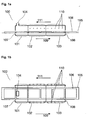
- FIGS 1 a and 1 b show, using common reference numbers, an industrial furnace 100, which is heated by burners 110 and comprising a dark zone 101 and two fired heating zones 102, 103.
- Hot combustion gases from burners 110 arranged in the zones 102, 103 circulate counter-currently through the furnace 100, in a general upstream direction 111, in order through the heating zone 103, through the heating zone 102 and thereafter through the dark zone 101, after which they escape through a flue or chimney 104.
- Burners 110 may be air burners, which is the preferred case in an upgrade according to below, but other burner types are also possible, including oxygen-assisted air burners or even burners driven directly with an oxidant comprising more oxygen than air. A mixture of such burners with air burners is also foreseeable. In the following, it is understood that burners 110 may be of such different types.
- Metal material 106 to be heated is transported in a general downstream direction 109, opposite to the direction 111, on a transport device 105 such as a conveyor belt or the like (see below), from a loading point 107 to an exit point 108.
- the metal material is in the form of blanks, slabs or billets, and is preferably constituted by steel, preferably stainless steel, preferably a steel material displaying low emissivity, such as for example a steel material having a grinded surface. Namely, such steels are particularly suitable for use with the improved thermal energy transfer efficiency offered by the method of the present invention.
- the furnace 100 is preferably a walking beam furnace, a pusher furnace or an annular furnace, and the transport device 105 is thus of a suitable type for the type of furnace in question.
- the term "dark zone” is to be interpreted as a zone which preferably is arranged upstream, in relation to the travel direction 109 of the metal material 106, of any heating zone 102, 103 which is heated using one or several burners 110.
- the dark zone 101 is arranged upstream, as seen in direction 109, of all fuel supply points in the industrial furnace 100.
- the dark zone 101 is arranged to preheat metal material 106 which has been loaded into the furnace 100 before reaching the first fired heating zone 102.
- Both heating zones 102, 103 are thus heated using a series of burners 110 arranged along the side walls of the furnace 100.
- the burners are operated using a solid, liquid or gaseous fuel which is combusted with the supplied oxidant, such as air, thus heating spaces 102, 103.
- the combustion products comprising nitrogen, carbon dioxide, water etc., circulate counter-currently, in direction 111, through the furnace 100 upstream towards the exit 104.
- the furnace may comprise only one heating zone, or more than two heating zones.
- FIGS. 2a and 2b show, with shared reference numbers, an industrial furnace 200 according to the present invention. That what has been said in relation to the furnace 100 is, in applicable cases, true also in relation to the furnace 200.
- the furnace 200 similarly to the furnace 100 the furnace 200 comprises a dark zone 201 and two heating zones 202, 203.
- Metal material 206 is transported, in a general direction 209, by a transport device 205 from a loading entry point 207 to an exit 208.
- Combustion gases originating from a series of burners 210 arranged in the heating zones 202, 203, circulate counter-currently, in a general upstream direction 211, along the furnace 200 and are evacuated through a flue or chimney 204.
- burners 210 are preferably air burners, most preferably only air burners, but may also be driven partly or completely, or be assisted, by an oxidant comprising more oxygen than air.
- the lambda value of the combustion in at least one of the said at least one heating zones 202, 203 is below one.
- the lambda value is the ratio of the actual oxygen-to-fuel ratio and the oxygen-to-fuel ratio when at stoichiometric equilibrium.
- the supply of oxygen and fuel to the burners 110 is balanced, so that combustion is performed at stoichiometric equilibrium.
- the supply of oxygen and/or fuel to the burners 210 which heat the zones 202, 203 of furnace 200 has been modified so that comparatively less oxygen is supplied in relation to the amount of supplied fuel.
- the resulting combustion gases circulating from the most upstream located heating zone 202 and into the dark zone 201 will carry a surplus of combustible gases. It is realized that such combustible gases may be in the form of non-combusted fuel gases and/or combustible gases in the form of CO, H 2 or the like, resulting from incomplete combustion of fuel in the heating zones 202, 203.
- the said lambda value of below one is achieved by decreasing the amount of air supplied to the said air burner 210.
- an oxidant comprising at least 85 percentages by weight, preferably at least 95 percentages by weight, preferably industrially pure, oxygen is supplied through at least one oxidant lance 212 arranged to open out into the dark zone 201.
- at least one stream 213 of the said high-oxygen oxidant is directed towards the metal material 206.
- the said high-oxygen oxidant will, in the dark zone 201, combust the above-described combustible surplus gases originating from the at least one upstream heating zone 202, 203.
- the total combustion, counting combustion in all heating zones 202, 203 and the dark zone 201 will add up to stoichiometric equilibrium, or at least near stoichiometric equilibrium, so that essentially all fuel is combusted before the combustion products are evacuated through the flue 204.
- the nitrogen ballast decreases, which in turn increases the efficiency of the furnace 200.
- the additional combustion taking place as the lanced oxidant comes into contact with the combustible gases from the heating zones 202, 203 will result in a temperature increase in the dark zone. This solves the problem of low thermal transfer rates to the metal material 206 in the dark zone 201 when only replacing air burners 210 with oxyfuel burners, as discussed initially.
- the flame temperature in the dark zone 201 will consequently also be lower. This leads to less NO x formation. As a result, the total NO x footprint of the process will be decreased as compared to the corresponding conventional case.
- the high-oxygen oxidant is lanced towards the surface of the still relatively cold metal material 206, the extra heat is directed onto the said surface, whereby the metal material will be efficiently preheated.
- the lancing of the high-oxygen oxidant should preferably not result in said oxidant coming into direct contact with the metal material 206 surface.
- the relation between on the one hand the amount of the oxygen lanced per time unit and per oxidant lance 212 in the lanced high-oxygen oxidant, and on the other hand the distance between the lance 212 orifice and the metal material 206, is such that the lanced oxidant mixes with the combustible gases present in the dark zone 201 before it strikes the surface of the metal material 206, and so that no unmixed oxidant comes into direct contact with the metal material 206.
- the amount of lanced oxygen is sufficiently small and the distance between the lance 212 orifice and the metal material 206 is sufficiently large so that the oxidant will mix with the combustible gases in the dark zone 201 sufficiently, so that essentially no un-mixed high-oxygen oxidant reaches the metal material 206 surface. It is preferred that the said small amount of lanced oxygen and said large distance between lance orifice 212 and material 206 is to be established given a certain lancing velocity, which should be high (see below), and possibly also a given oxygen concentration in the lanced oxidant.
- the distance H between the lance 212 orifice and the metal material 206, as measured in the direction of the lance 212, is preferably at least 1.5 meters, more preferably at least 2 meters.
- H indicates the vertical distance since the lance 212 is directed vertically. It is realized that if the lance is inclined, the distance H will be measured in a direction which is not vertical.
- a "soft" flame can be arranged across a large portion of, or essentially the whole, width of the metal material 206, efficiently preheating the same while passing through the dark zone 201.
- the flame is illustrated by a combustion zone 214, throughout which the secondary combustion, between lanced oxidant and incompletely combusted gases, takes place.
- At least one row, preferably at least two essentially parallel rows, arranged essentially perpendicularly to the direction 209, of high-oxygen oxidant lances 212 are arranged with at least three lances in each row, thus achieving an essentially uniform concentration of high-oxygen oxidant across the whole width, perpendicularly to the direction 209, of the metal material 206.
- At least one such lance 212 is arranged in the ceiling of the dark zone 201, and that the associated stream 213 of oxidant is directed essentially downwards towards the metal material 206 surface.
- the stream 213 may also be slightly inclined in the direction 209, such that the stream 213 is offset from the vertical towards the heating zone 202. Suitable angles are about 5-15° from the vertical.
- roof-mounted lances may be supplemented by lances mounted in the side walls of the dark zone 201, in order to achieve an even more uniform temperature profile of the gases surrounding the metal material 206.
- the lances can be inclined so that the lanced high-oxygen oxidant propels the furnace gases in the downstream direction 209. This increases the turbulence, and hence increases the flame size, which in turn decreases the risk of overheating.
- inclined lances may be useful in the downstream-most arranged part of the dark zone 201, in order to improve the mixing of the combustion products arriving from the heated zones 202, 203 with the lanced high-oxygen oxidant.
- Preferred lancing angles are in this case between 30 and 45° in relation to the vertical and inclined with the lance 212 orifice towards the downstream direction 209.
- the combustion power of the combustion reaction involving the lanced high-oxygen oxidant and the excess fuel supplied by burners 210 is at most about 10% of the total combustion power of the furnace 200.
- the total amount of supplied oxidant per unit time is small, preferably only between 1/10 and 1/100 of the volume, in comparison to the amount of combustion gases circulating through the dark zone 201 per unit time.
- the velocity of the oxidant at the orifice of the or each lance 212 is at least 100 m/s, more preferably between 300 m/s and 450 m/s.
- the combination of relatively small lanced volumes and high lancing velocities will produce a very high-turbulence, diluted, "soft" flame which is pushed downwards towards the surface of the metal material 206, efficiently preheating the same without risking overheating. It is preferred that about between 200-500 Nm 3 /h high-oxygen oxidant is provided through each lance.
- a conventional furnace such as the furnace 100
- an industrial furnace 100 which before the upgrade is arranged to be heated only by the use of one or several existing burners 110 and which comprises a dark zone 101 and at least one heating zone 102, 103 arranged downstream of the dark zone 101, which heating zone 102, 103 is arranged to be heated using said burners 110, wherein metal material 106 is transported through the dark zone 101 and thereafter through the heating zone 102, 103, and wherein combustion gases circulate counter-currently through the furnace 100 through the heating zones 103 and 102 and thereafter through the dark zone 101, is upgraded by supplementing it with at least one oxidant lance 212 arranged to supply a stream 213 of an oxidant comprising at least 85%, preferably at least 95%, preferably industrially pure, oxygen to the dark zone 101.
- the furnace 100 is operated as described above in connection with figures 2a and 2b .
- the amount of oxygen supplied via the at least one burner 110 is decreased as compared to the operation before the upgrade, whereby the lambda value of the heating zones 102, 103 is decreased, and the resulting decrease in oxygen supply is compensated for by the lanced high-oxygen oxidant.
- the lanced high-oxygen oxidant Preferably, about 10%-50%, more preferably about 20%-30% of the total oxygen requirement of those burners which are operated in an oxygen-decreased state will be provided by the lanced high-oxygen oxidant.
- At least one of the at least one existing burners 110 is an existing air burner
- the said decreased supplied oxygen amount is achieved by decreasing the amount of air supplied to the said at least one existing air burner.
- Such an upgrade is very cost efficient as compared to the replacement of some or all of the burners 110 with corresponding oxyfuel burners, and solves the initially discussed problems.
- the amount of metal material 106 loaded per time unit during the operation is increased as compared to operation before the upgrade, so as to maintain essentially the same flue gas temperature at the flue gas exit 104 from the dark zone 201.
- the efficiency increase caused by the introduction of high-oxygen oxidant is preferably used to increase the production rate rather than to decrease the amount of fuel used.
- the amount of the above described fuel provided to the heated zones 202, 203 per time unit can be increased in order to achieve the said lambda values below one.
- the loading rate is adjusted so that the gas temperature at the exit 104 is kept at about 800-900°C.
- the resulting content of incompletely combusted, combustible gases (CO and H 2 ) corresponds to 2 MW, which was combusted using 320 Nm 3 /h lanced industrially pure oxygen in the dark zone.
- the final, total combustion products composition was: Exhaust gas composition %-wet Nm 3 /h CO 2 9,3 4622 H 2 O 17,9 8847 SO 2 0,0 0 O 2 1,2 601 N 2 71,6 35423
- the introduction of high-oxygen oxidant lances in the dark zone also results in increased control over the temperature profile along the length of the furnace.
- the amount of lanced high-oxygen oxidant via each such row may be adjusted depending on the desired such temperature profile.
- the proportion of the total oxygen supplied via lancing may be adjusted during operation or between batches, depending on the desired preheating in the dark zone.
Landscapes
- Engineering & Computer Science (AREA)
- Mechanical Engineering (AREA)
- General Engineering & Computer Science (AREA)
- Furnace Details (AREA)
- Tunnel Furnaces (AREA)
- Furnace Charging Or Discharging (AREA)
- Regulation And Control Of Combustion (AREA)
- Combustion Of Fluid Fuel (AREA)
Abstract
Method for heating a metal material (206) in an industrial furnace (200) comprising a dark zone (201) and at least one heating zone (202,203) arranged downstream of the dark zone (201), which heating zone (202,203) is heated using at least one burner (210), wherein said metal material (206) is transported through the dark zone (201) and thereafter through the heating zone (202,203), and wherein combustion gases circulate counter-currently through the industrial furnace (200) through the at least one heating zone (202,203) and thereafter through the dark zone (201).
The invention is characterised in that the lambda value, in other words the ratio of the actual oxygen-to-fuel ratio and the stoichiometric oxygen-to-fuel ratio, of the combustion in at least one of said at least one heating zones (202,203) is below one, and in that an oxidant comprising at least 85 percentages by weight oxygen is supplied through at least one lance (212) into the dark zone (201), so that at least one stream (213) of the said oxidant is directed towards the metal material (206) and so that the said oxidant in the dark zone (201) combusts combustible gases originating from the at least one heating zone (202,203).
Description
- The present invention relates to a method for heating metal material in an industrial furnace. The invention also relates to a method for upgrading an air burner heated industrial furnace in order to increase the combustion efficiency.
- Metal materials, such as slabs, billets and blooms, are conventionally heated in industrial furnaces which are heated using air burners, where combustion of a fuel takes place with air supplied by the burner. In counter-flow furnaces, the combustion products flow upstream in relation to the transport direction of the metal material, thereby heating the material which is approaching the air burners. In such furnaces, there is conventionally a so-called dark zone, in which loaded metal material is pre-heated by the counter-currently flowing combustion gases before entering the heating zone or zones of the furnace.
- A problem is that air combustion is inefficient, since large volumes of nitrogen are heated in the process. It is therefore desirable to use high-oxygen oxidants to replace air in the above described furnaces.
- It has for such furnaces been suggested to replace air burners with so-called oxyfuel burners, that is, burners fed with a high-oxygen oxidant rather than with air. However, in addition to such burners being expensive to install, this leads to smaller volumes of combustion products flowing through the furnace and the dark zone, and therefore that the loaded metal products are preheated less efficiently. In order to solve this problem, it has been proposed to lower the ceiling in the dark zone, thereby decreasing the volume of the dark zone and improving the preheating of the metal products therein per unit volume of combustion products. However, this leads to increased pressures in the main furnace space, downstream of the dark zone, increasing the risk of leaks therein.
- Another possibility is to arrange additional burners in the dark zone. However, this has proven expensive and complicated, not least since many furnaces are quite broad and it is difficult to obtain even heating across the whole width of the metal products to be preheated without risking overheating of the metal material surface.
- The present invention solves the above described problems.
- Thus, the invention relates to a method for heating a metal material in an industrial furnace comprising a dark zone and at least one heating zone arranged downstream of the dark zone, which heating zone is heated using at least one burner, wherein said metal material is transported through the dark zone and thereafter through the heating zone, and wherein combustion gases circulate counter-currently through the industrial furnace through the at least one heating zone and thereafter through the dark zone, and is characterised in that the lambda value, in other words the ratio of the actual oxygen-to-fuel ratio and the stoichiometric oxygen-to-fuel ratio, of the combustion in at least one of said at least one heating zones is below one, and in that an oxidant comprising at least 85 percentages by weight oxygen is supplied through at least one lance into the dark zone, so that at least one stream of the said oxidant is directed towards the metal material and so that the said oxidant in the dark zone combusts combustible gases originating from the at least one heating zone.
- In the following, the invention will be described in detail, with reference to exemplifying embodiments of the invention and to the appended drawings, where:
-
Figure 1 a is a simplified, partly removed side view of a conventional industrial furnace which is heated using air burners; -
Figure 1b is a simplified, partly removed top view of the furnace offigure 1 a; -
Figure 2a is a simplified, partly removed side view of an industrial furnace arranged for operation using a method according to the present invention; andFigure 2b is a simplified, partly removed top view of the furnace offigure 2a . -
Figures 1 a and 1 b show, using common reference numbers, anindustrial furnace 100, which is heated byburners 110 and comprising adark zone 101 and two firedheating zones burners 110 arranged in thezones furnace 100, in a generalupstream direction 111, in order through theheating zone 103, through theheating zone 102 and thereafter through thedark zone 101, after which they escape through a flue orchimney 104.Burners 110 may be air burners, which is the preferred case in an upgrade according to below, but other burner types are also possible, including oxygen-assisted air burners or even burners driven directly with an oxidant comprising more oxygen than air. A mixture of such burners with air burners is also foreseeable. In the following, it is understood thatburners 110 may be of such different types. -
Metal material 106 to be heated is transported in a generaldownstream direction 109, opposite to thedirection 111, on atransport device 105 such as a conveyor belt or the like (see below), from aloading point 107 to anexit point 108. It is preferred that the metal material is in the form of blanks, slabs or billets, and is preferably constituted by steel, preferably stainless steel, preferably a steel material displaying low emissivity, such as for example a steel material having a grinded surface. Namely, such steels are particularly suitable for use with the improved thermal energy transfer efficiency offered by the method of the present invention. Thefurnace 100 is preferably a walking beam furnace, a pusher furnace or an annular furnace, and thetransport device 105 is thus of a suitable type for the type of furnace in question. - Herein, the term "dark zone" is to be interpreted as a zone which preferably is arranged upstream, in relation to the
travel direction 109 of themetal material 106, of anyheating zone several burners 110. Preferably, thedark zone 101 is arranged upstream, as seen indirection 109, of all fuel supply points in theindustrial furnace 100. Thedark zone 101 is arranged to preheatmetal material 106 which has been loaded into thefurnace 100 before reaching the first firedheating zone 102. - Both
heating zones burners 110 arranged along the side walls of thefurnace 100. Preferably, the burners are operated using a solid, liquid or gaseous fuel which is combusted with the supplied oxidant, such as air, thusheating spaces direction 111, through thefurnace 100 upstream towards theexit 104. - It is realized that the furnace may comprise only one heating zone, or more than two heating zones.
-
Figures 2a and 2b show, with shared reference numbers, anindustrial furnace 200 according to the present invention. That what has been said in relation to thefurnace 100 is, in applicable cases, true also in relation to thefurnace 200. Thus, similarly to thefurnace 100 thefurnace 200 comprises adark zone 201 and twoheating zones Metal material 206 is transported, in ageneral direction 209, by atransport device 205 from aloading entry point 207 to anexit 208. Combustion gases, originating from a series ofburners 210 arranged in theheating zones upstream direction 211, along thefurnace 200 and are evacuated through a flue orchimney 204. Similarly toburners 110,burners 210 are preferably air burners, most preferably only air burners, but may also be driven partly or completely, or be assisted, by an oxidant comprising more oxygen than air. - In the following, the differences between the
conventional furnace 100 and thefurnace 200 according to the invention will be described. - According to the invention, the lambda value of the combustion in at least one of the said at least one
heating zones industrial furnace 100 offigures 1 a and 1 b, the supply of oxygen and fuel to theburners 110 is balanced, so that combustion is performed at stoichiometric equilibrium. However, in contrast thereto, the supply of oxygen and/or fuel to theburners 210 which heat thezones furnace 200 has been modified so that comparatively less oxygen is supplied in relation to the amount of supplied fuel. As a consequence, the resulting combustion gases circulating from the most upstream locatedheating zone 202 and into thedark zone 201 will carry a surplus of combustible gases. It is realized that such combustible gases may be in the form of non-combusted fuel gases and/or combustible gases in the form of CO, H2 or the like, resulting from incomplete combustion of fuel in theheating zones - It is understood that in the preferred embodiment in which the
burner 210 is an air burner, the said lambda value of below one is achieved by decreasing the amount of air supplied to the saidair burner 210. - Furthermore, according to the invention, an oxidant comprising at least 85 percentages by weight, preferably at least 95 percentages by weight, preferably industrially pure, oxygen is supplied through at least one
oxidant lance 212 arranged to open out into thedark zone 201. As a consequence, at least onestream 213 of the said high-oxygen oxidant is directed towards themetal material 206. Also, the said high-oxygen oxidant will, in thedark zone 201, combust the above-described combustible surplus gases originating from the at least oneupstream heating zone - It is preferred that the total combustion, counting combustion in all
heating zones dark zone 201, will add up to stoichiometric equilibrium, or at least near stoichiometric equilibrium, so that essentially all fuel is combusted before the combustion products are evacuated through theflue 204. By decreasing the amount of oxygen supplied through the burners, and replacing the decreased amounts of oxygen resulting from the smaller amounts of oxygen using the lanced high-oxygen oxidant in the dark zone, the nitrogen ballast decreases, which in turn increases the efficiency of thefurnace 200. The additional combustion taking place as the lanced oxidant comes into contact with the combustible gases from theheating zones metal material 206 in thedark zone 201 when only replacingair burners 210 with oxyfuel burners, as discussed initially. - As the combustion in the
dark zone 201 involves a lower-grade fuel (namely, diluted incomplete combustion products) than the combustion in theheating zones dark zone 201 will consequently also be lower. This leads to less NOx formation. As a result, the total NOx footprint of the process will be decreased as compared to the corresponding conventional case. - Moreover, since the high-oxygen oxidant is lanced towards the surface of the still relatively
cold metal material 206, the extra heat is directed onto the said surface, whereby the metal material will be efficiently preheated. - The fact that the surface of the
metal material 206 is still relatively cold while still in the dark zone makes it less prone to overheating. - On the other hand, the lancing of the high-oxygen oxidant should preferably not result in said oxidant coming into direct contact with the
metal material 206 surface. According to one preferred embodiment, the relation between on the one hand the amount of the oxygen lanced per time unit and per oxidant lance 212 in the lanced high-oxygen oxidant, and on the other hand the distance between thelance 212 orifice and themetal material 206, is such that the lanced oxidant mixes with the combustible gases present in thedark zone 201 before it strikes the surface of themetal material 206, and so that no unmixed oxidant comes into direct contact with themetal material 206. In other words, the amount of lanced oxygen is sufficiently small and the distance between thelance 212 orifice and themetal material 206 is sufficiently large so that the oxidant will mix with the combustible gases in thedark zone 201 sufficiently, so that essentially no un-mixed high-oxygen oxidant reaches themetal material 206 surface. It is preferred that the said small amount of lanced oxygen and said large distance betweenlance orifice 212 andmaterial 206 is to be established given a certain lancing velocity, which should be high (see below), and possibly also a given oxygen concentration in the lanced oxidant. - The distance H between the
lance 212 orifice and themetal material 206, as measured in the direction of thelance 212, is preferably at least 1.5 meters, more preferably at least 2 meters. Infigure 2a , H indicates the vertical distance since thelance 212 is directed vertically. It is realized that if the lance is inclined, the distance H will be measured in a direction which is not vertical. - This way, the lancing action will push the high-temperature gases in the
dark zone 201 towards the surface of themetal material 206 without risking overheating of the latter as a consequence. Instead, a "soft" flame can be arranged across a large portion of, or essentially the whole, width of themetal material 206, efficiently preheating the same while passing through thedark zone 201. In the figures, the flame is illustrated by acombustion zone 214, throughout which the secondary combustion, between lanced oxidant and incompletely combusted gases, takes place. - To accomplish this, it is preferred that at least one row, preferably at least two essentially parallel rows, arranged essentially perpendicularly to the
direction 209, of high-oxygen oxidant lances 212 are arranged with at least three lances in each row, thus achieving an essentially uniform concentration of high-oxygen oxidant across the whole width, perpendicularly to thedirection 209, of themetal material 206. - It is especially preferred that at least one
such lance 212 is arranged in the ceiling of thedark zone 201, and that the associatedstream 213 of oxidant is directed essentially downwards towards themetal material 206 surface. However, thestream 213 may also be slightly inclined in thedirection 209, such that thestream 213 is offset from the vertical towards theheating zone 202. Suitable angles are about 5-15° from the vertical. It is also realized that roof-mounted lances may be supplemented by lances mounted in the side walls of thedark zone 201, in order to achieve an even more uniform temperature profile of the gases surrounding themetal material 206. - Alternatively, the lances can be inclined so that the lanced high-oxygen oxidant propels the furnace gases in the
downstream direction 209. This increases the turbulence, and hence increases the flame size, which in turn decreases the risk of overheating. In particular, such inclined lances may be useful in the downstream-most arranged part of thedark zone 201, in order to improve the mixing of the combustion products arriving from theheated zones lance 212 orifice towards thedownstream direction 209. - In order to avoid the risk of overheating the
metal material 206 surface, it is preferred that only a minor part of the totally supplied oxygen originates from the lanced high-oxygen oxidant. According to one preferred embodiment, the combustion power of the combustion reaction involving the lanced high-oxygen oxidant and the excess fuel supplied byburners 210 is at most about 10% of the total combustion power of thefurnace 200. Thus, the total amount of supplied oxidant per unit time is small, preferably only between 1/10 and 1/100 of the volume, in comparison to the amount of combustion gases circulating through thedark zone 201 per unit time. - Furthermore, it is preferred the velocity of the oxidant at the orifice of the or each
lance 212 is at least 100 m/s, more preferably between 300 m/s and 450 m/s. The combination of relatively small lanced volumes and high lancing velocities will produce a very high-turbulence, diluted, "soft" flame which is pushed downwards towards the surface of themetal material 206, efficiently preheating the same without risking overheating. It is preferred that about between 200-500 Nm3/h high-oxygen oxidant is provided through each lance. - According to a particularly preferred embodiment, a conventional furnace, such as the
furnace 100, is upgraded for operation according to the present invention. In other words, anindustrial furnace 100 which before the upgrade is arranged to be heated only by the use of one or several existingburners 110 and which comprises adark zone 101 and at least oneheating zone dark zone 101, whichheating zone burners 110, whereinmetal material 106 is transported through thedark zone 101 and thereafter through theheating zone furnace 100 through theheating zones dark zone 101, is upgraded by supplementing it with at least oneoxidant lance 212 arranged to supply astream 213 of an oxidant comprising at least 85%, preferably at least 95%, preferably industrially pure, oxygen to thedark zone 101. Thereafter, thefurnace 100 is operated as described above in connection withfigures 2a and 2b . Thus, the amount of oxygen supplied via the at least oneburner 110 is decreased as compared to the operation before the upgrade, whereby the lambda value of theheating zones - It is understood that in the preferred embodiment in which at least one of the at least one existing
burners 110 is an existing air burner, that the said decreased supplied oxygen amount is achieved by decreasing the amount of air supplied to the said at least one existing air burner. - Such an upgrade is very cost efficient as compared to the replacement of some or all of the
burners 110 with corresponding oxyfuel burners, and solves the initially discussed problems. - Since the total amounts of combustion gases escaping through the
flue 104 will be less than before the upgrade at a given total combustion power, it is preferred that the amount ofmetal material 106 loaded per time unit during the operation is increased as compared to operation before the upgrade, so as to maintain essentially the same flue gas temperature at theflue gas exit 104 from thedark zone 201. In other words, the efficiency increase caused by the introduction of high-oxygen oxidant is preferably used to increase the production rate rather than to decrease the amount of fuel used. - Instead of, or in addition to, the above described decrease of the oxygen provided to the
burners 210, the amount of the above described fuel provided to theheated zones - Furthermore, it is preferred that the loading rate is adjusted so that the gas temperature at the
exit 104 is kept at about 800-900°C. - As an example, an air burner fired furnace with 3 heating zones (in order of material transport direction Z1 = 20 MW, Z2 = 20 MW and Z3 = 5 MW) was upgraded according to the present invention by mounting high-oxygen oxidant lances in the roof of the dark zone.
- After the upgrade, the most downstream arranged zones Z2 and Z3 were fired in a conventional manner with 26819 Nm3/h air and 2457 Nm3/h natural gas (total combustion power 25 MW). The resulting combustion products had the following composition:
Exhaust gas composition %-wet Nm3/h CO2 8,7 2568 H2O 16,7 4915 SO2 0,0 0 O2 2,0 587 N2 72,6 21310 - In contrast to zones Z2 and Z3, the originally 20 MW zone Z1 was fired with an oxygen deficit, so that only 18 MW was combusted with air supplied via the existing air burners. 1966 Nm3/h natural gas was combusted with 17745 Nm3/h air. The combustion gases resulting from this combustion, with lambda = 0,924, in zone Z1 had the following composition:
Exhaust gas composition %-wet Nm3/h CO2 8,6 1725 H2O 18,2 3650 SO2 0,0 0 O2 0,0 0 H2 1,4 282 CO 1,64 329 N2 70,2 14113 - The resulting content of incompletely combusted, combustible gases (CO and H2) corresponds to 2 MW, which was combusted using 320 Nm3/h lanced industrially pure oxygen in the dark zone. The final, total combustion products composition was:
Exhaust gas composition %-wet Nm3/h CO2 9,3 4622 H2O 17,9 8847 SO2 0,0 0 O2 1,2 601 N2 71,6 35423 - Above, preferred embodiments have been described. However, it is apparent to the skilled person that many modifications may be made to the described embodiments without departing from the idea of the invention.
- As an example, the introduction of high-oxygen oxidant lances in the dark zone also results in increased control over the temperature profile along the length of the furnace. In case several rows of such lances are installed, the amount of lanced high-oxygen oxidant via each such row may be adjusted depending on the desired such temperature profile. Also, the proportion of the total oxygen supplied via lancing may be adjusted during operation or between batches, depending on the desired preheating in the dark zone.
- Thus, the invention shall not be limited to the described embodiments, but may be varied within the scope of the enclosed claims.
Claims (14)
- Method for heating a metal material (206) in an industrial furnace (200) comprising a dark zone (201) and at least one heating zone (202,203) arranged downstream of the dark zone (201), which heating zone (202,203) is heated using at least one burner (210), wherein said dark zone (101) is arranged upstream of all fuel supply points in the industrial furnace, wherein said metal material (206) is transported through the dark zone (201) and thereafter through the heating zone (202,203), and wherein combustion gases circulate counter-currently through the industrial furnace (200) through the at least one heating zone (202,203) and thereafter through the dark zone (201), characterised in that the lambda value, in other words the ratio of the actual oxygen-to-fuel ratio and the stoichiometric oxygen-to-fuel ratio, of the combustion in at least one of said at least one heating zones (202,203) is below one, and in that an oxidant comprising at least 85 percentages by weight oxygen is supplied through at least one lance (212) into the dark zone (201), so that at least one stream (213) of the said oxidant is directed towards the metal material (206) and so that the said oxidant in the dark zone (201) combusts combustible gases originating from the at least one heating zone (202,203).
- Method according to claim 1, characterised in that the said burner (210) is an air burner, and that the said lambda value of below one is achieved by decreasing the amount of air supplied to the said air burner.
- Method according to claim 1 or 2, characterised i n that the at least one lance (212) is arranged in the ceiling of the dark zone (201), and in that said at least one stream (213) of oxidant is directed downwards towards the metal material (206).
- Method according to any one of the preceding claims, characterised i n that the combustion power of the combustion involving the said oxidant and the excess fuel provided in the at least one heating zone (202,203) is at most about 10% of the total combustion power of the industrial furnace (200).
- Method according to any one of the preceding claims, characterised in that the industrial furnace (200) is a walking beam furnace, a pusher furnace or an annular furnace.
- Method according to any one of the preceding claims, characterised i n that the relation between on the one hand the amount of the oxygen lanced per time unit and per oxidant lance (212) in the lanced high-oxygen oxidant and on the other hand the distance between each lance (212) orifice and the metal material (206) is such that, for a given lancing velocity, the oxidant mixes with the combustible gases present in the dark zone (201) before it strikes the surface of the metal material (206), and so that essentially no unmixed oxidant comes into direct contact with the metal material (206).
- Method according to claim 6, characterised i n that the distance (H) between the lance (212) orifice and the metal material (206) as measured in the lancing direction is at least 2 meters.
- Method according to claim 6 or 7, characterised in that the velocity of the oxidant at the orifice of the lance (212) is at least 100 m/s.
- Method according to claim 8, characterised in that the velocity of the oxidant at the orifice of the lance (212) is between 300 m/s and 450 m/s.
- Method according to any one of the preceding claims, characterised in that the oxidant comprises at least 95 percent oxygen.
- Method for upgrading an existing industrial furnace (100), which industrial furnace (100) before the upgrade is arranged to be heated only by the use of one or several existing burners (110) and which comprises a dark zone (101) and at least one heating zone (102,103) arranged downstream of the dark zone (101), which heating zone (102,103) is arranged to be heated using at least one burner (110), wherein a metal material (106) to be heated is arranged to be transported through the dark zone (101) and thereafter the heating zone (202,203), and wherein combustion gases are arranged to circulate counter-currently through the industrial furnace (100) through the at least one heating zone (102,103) and thereafter through the dark zone (101), characterised in that industrial furnace (100) is supplemented by at least one oxidant lance (212) arranged to supply a stream (213) of an oxidant comprising at least 85% oxygen to the dark zone (100), and in that the industrial furnace (100) is then operated according to the method of any one of the preceding claims, whereby the amount of oxygen supplied via the at least one existing burner (110) is decreased as compared to the operation before the upgrade and the resulting decrease in oxygen supply is compensated for by the lanced oxidant.
- Method according to claim 11, characterised in that at least one of the said at least one existing burners (110) is an existing air burner, and that the said decreased supplied oxygen amount is achieved by decreasing the amount of air supplied to the said at least one existing air burner.
- Method according to claim 11 or 12, characterised in that the amount of metal material (106) loaded per time unit during the operation according to any one of claims 1-9 is increased as compared to operation before the upgrade, so as to maintain essentially the same flue gas temperature at a flue gas exit (104) from the dark zone (101).
- Method according to any one of claims 11-13, characterised in
that the lance (212) is arranged in the ceiling of the dark zone (101), so that that said stream (213) of oxidant is arranged to be directed downwards towards the metal material (106).
Priority Applications (1)
| Application Number | Priority Date | Filing Date | Title |
|---|---|---|---|
| EP14003680.7A EP2891859A1 (en) | 2013-12-12 | 2014-10-30 | Method for heating a metal material in an industrial furnace |
Applications Claiming Priority (2)
| Application Number | Priority Date | Filing Date | Title |
|---|---|---|---|
| EP13005793 | 2013-12-12 | ||
| EP14003680.7A EP2891859A1 (en) | 2013-12-12 | 2014-10-30 | Method for heating a metal material in an industrial furnace |
Publications (1)
| Publication Number | Publication Date |
|---|---|
| EP2891859A1 true EP2891859A1 (en) | 2015-07-08 |
Family
ID=49882754
Family Applications (1)
| Application Number | Title | Priority Date | Filing Date |
|---|---|---|---|
| EP14003680.7A Withdrawn EP2891859A1 (en) | 2013-12-12 | 2014-10-30 | Method for heating a metal material in an industrial furnace |
Country Status (7)
| Country | Link |
|---|---|
| EP (1) | EP2891859A1 (en) |
| JP (1) | JP2015114101A (en) |
| KR (1) | KR20150068918A (en) |
| CN (1) | CN104713352A (en) |
| AU (1) | AU2014271304A1 (en) |
| BR (1) | BR102014030393A2 (en) |
| RU (1) | RU2014150371A (en) |
Cited By (3)
| Publication number | Priority date | Publication date | Assignee | Title |
|---|---|---|---|---|
| EP3839340A1 (en) * | 2019-12-18 | 2021-06-23 | Linde GmbH | Method and device for heating a furnace |
| IT202000013285A1 (en) * | 2020-06-04 | 2021-12-04 | Danieli Off Mecc | PROCEDURE AND APPARATUS FOR HEATING STEEL PRODUCTS |
| RU2804206C1 (en) * | 2021-06-04 | 2023-09-26 | Даниэли энд К. Оффичине Мекканике С.п.А. | Device for heating steel products |
Families Citing this family (2)
| Publication number | Priority date | Publication date | Assignee | Title |
|---|---|---|---|---|
| PL3412999T3 (en) * | 2017-06-06 | 2020-05-18 | Linde Aktiengesellschaft | Method and device for heating a furnace |
| EP3649468A1 (en) * | 2017-07-03 | 2020-05-13 | Linde Aktiengesellschaft | Method and system for analysing a fuel gas |
Citations (5)
| Publication number | Priority date | Publication date | Assignee | Title |
|---|---|---|---|---|
| US6350118B1 (en) * | 1994-06-08 | 2002-02-26 | L'air Liquide, Societe Anonyme Pour L'etude Et L'exploitation Des Procedes Georges Claude | Combustion assembly for a furnace and method of use |
| US20020050670A1 (en) * | 2000-09-08 | 2002-05-02 | Olivier Delabroy | Method of reheating metallurgical products |
| EP2230453A2 (en) * | 2009-03-20 | 2010-09-22 | Aga Ab | Method for homogenizing the heat distribution as well as decreasing the amount of NOx |
| EP2437019A1 (en) * | 2010-09-30 | 2012-04-04 | Linde AG | Method for use when carrying out combustion in an industrial furnace |
| EP2645036A1 (en) * | 2012-03-27 | 2013-10-02 | Linde Aktiengesellschaft | Method for heating a metal slab |
-
2014
- 2014-10-30 EP EP14003680.7A patent/EP2891859A1/en not_active Withdrawn
- 2014-12-04 AU AU2014271304A patent/AU2014271304A1/en not_active Abandoned
- 2014-12-04 BR BRBR102014030393-6A patent/BR102014030393A2/en not_active IP Right Cessation
- 2014-12-11 RU RU2014150371A patent/RU2014150371A/en not_active Application Discontinuation
- 2014-12-11 KR KR1020140178747A patent/KR20150068918A/en not_active Withdrawn
- 2014-12-12 CN CN201410771797.5A patent/CN104713352A/en active Pending
- 2014-12-12 JP JP2014252391A patent/JP2015114101A/en active Pending
Patent Citations (5)
| Publication number | Priority date | Publication date | Assignee | Title |
|---|---|---|---|---|
| US6350118B1 (en) * | 1994-06-08 | 2002-02-26 | L'air Liquide, Societe Anonyme Pour L'etude Et L'exploitation Des Procedes Georges Claude | Combustion assembly for a furnace and method of use |
| US20020050670A1 (en) * | 2000-09-08 | 2002-05-02 | Olivier Delabroy | Method of reheating metallurgical products |
| EP2230453A2 (en) * | 2009-03-20 | 2010-09-22 | Aga Ab | Method for homogenizing the heat distribution as well as decreasing the amount of NOx |
| EP2437019A1 (en) * | 2010-09-30 | 2012-04-04 | Linde AG | Method for use when carrying out combustion in an industrial furnace |
| EP2645036A1 (en) * | 2012-03-27 | 2013-10-02 | Linde Aktiengesellschaft | Method for heating a metal slab |
Cited By (9)
| Publication number | Priority date | Publication date | Assignee | Title |
|---|---|---|---|---|
| EP3839340A1 (en) * | 2019-12-18 | 2021-06-23 | Linde GmbH | Method and device for heating a furnace |
| WO2021121663A1 (en) * | 2019-12-18 | 2021-06-24 | Linde Gmbh | Method and device for heating a furnace |
| CN114746697A (en) * | 2019-12-18 | 2022-07-12 | 林德有限责任公司 | Method and device for heating a furnace |
| US20230003378A1 (en) * | 2019-12-18 | 2023-01-05 | Linde Gmbh | Method and device for heating a furnace |
| AU2020404402B2 (en) * | 2019-12-18 | 2026-01-08 | Linde Gmbh | Method and device for heating a furnace |
| IT202000013285A1 (en) * | 2020-06-04 | 2021-12-04 | Danieli Off Mecc | PROCEDURE AND APPARATUS FOR HEATING STEEL PRODUCTS |
| WO2021245716A1 (en) * | 2020-06-04 | 2021-12-09 | Danieli & C. Officine Meccaniche S.P.A. | Apparatus for heating steel products |
| US12529520B2 (en) | 2020-06-04 | 2026-01-20 | Danieli & C. Officine Meccaniche S.P.A. | Apparatus for heating steel products |
| RU2804206C1 (en) * | 2021-06-04 | 2023-09-26 | Даниэли энд К. Оффичине Мекканике С.п.А. | Device for heating steel products |
Also Published As
| Publication number | Publication date |
|---|---|
| KR20150068918A (en) | 2015-06-22 |
| AU2014271304A1 (en) | 2015-07-02 |
| BR102014030393A2 (en) | 2015-07-14 |
| JP2015114101A (en) | 2015-06-22 |
| RU2014150371A (en) | 2016-07-10 |
| CN104713352A (en) | 2015-06-17 |
Similar Documents
| Publication | Publication Date | Title |
|---|---|---|
| CZ285317B6 (en) | Process of heating regenerative glass furnace and the regenerative glass melting furnace for making the same | |
| US20100213647A1 (en) | Process and installation for heating a metallic strip, notably for an annealing | |
| JP6542912B2 (en) | Low NOx combustion method | |
| US20150168067A1 (en) | Method for heating a metal material in an industrial furnace | |
| AU2014271304A1 (en) | Method for heating a metal material in an industrial furnace | |
| US6764304B2 (en) | Furnace having increased energy efficiency and reduced pollutant formation | |
| CN109234485B (en) | System and method for preheating metal-containing pellets | |
| CN101839473A (en) | Flue gas recirculation high temperature air energy-saving and environmental protection combustion technology | |
| EP2513345B1 (en) | Method for heatng a blast furnace stove | |
| CN103562148A (en) | Melting device | |
| EP2784388B1 (en) | Method for combustion of a low-grade fuel | |
| KR101879895B1 (en) | Apparatus and method for heating a blast furnace stove | |
| US20080153042A1 (en) | Integrated oxy-fuel combustion and nox control | |
| CN103392012A (en) | Method for heating blast furnace hot blast stove | |
| TWI670456B (en) | Method to reduce nitrogen oxides in strip processing furnaces | |
| US20100316969A1 (en) | Method of Heating a Mineral Feedstock in a Firing Furnace of the Tunnel Furnace Type | |
| KR102498261B1 (en) | Method for reducing nitrogen oxides in strip processing furnaces | |
| CA2694957A1 (en) | Reheat and tunnel furnace systems with reduced nitrogen oxides emissions | |
| TWI916748B (en) | Operating methods of heating furnace and heating furnace | |
| TWI901404B (en) | How to operate the heating furnace | |
| TWI901403B (en) | Heating furnace operation method and heating furnace | |
| CN107923709A (en) | For reheating the apparatus and method of metal product | |
| TWI903358B (en) | Operating methods and heating furnace | |
| JP2005300068A (en) | Control method of oxygen concentration and temperature of exhaust gas in rotary hearth type reduction furnace | |
| TW202436794A (en) | Operating method of heating furnace and heating furnace |
Legal Events
| Date | Code | Title | Description |
|---|---|---|---|
| PUAI | Public reference made under article 153(3) epc to a published international application that has entered the european phase |
Free format text: ORIGINAL CODE: 0009012 |
|
| 17P | Request for examination filed |
Effective date: 20141030 |
|
| AK | Designated contracting states |
Kind code of ref document: A1 Designated state(s): AL AT BE BG CH CY CZ DE DK EE ES FI FR GB GR HR HU IE IS IT LI LT LU LV MC MK MT NL NO PL PT RO RS SE SI SK SM TR |
|
| AX | Request for extension of the european patent |
Extension state: BA ME |
|
| STAA | Information on the status of an ep patent application or granted ep patent |
Free format text: STATUS: THE APPLICATION IS DEEMED TO BE WITHDRAWN |
|
| 18D | Application deemed to be withdrawn |
Effective date: 20160109 |