EP2891829A2 - Electromechanical actuator proximal position stopping assembly - Google Patents
Electromechanical actuator proximal position stopping assembly Download PDFInfo
- Publication number
- EP2891829A2 EP2891829A2 EP14191165.1A EP14191165A EP2891829A2 EP 2891829 A2 EP2891829 A2 EP 2891829A2 EP 14191165 A EP14191165 A EP 14191165A EP 2891829 A2 EP2891829 A2 EP 2891829A2
- Authority
- EP
- European Patent Office
- Prior art keywords
- ball nut
- ema
- housing
- proximal
- axially
- Prior art date
- Legal status (The legal status is an assumption and is not a legal conclusion. Google has not performed a legal analysis and makes no representation as to the accuracy of the status listed.)
- Pending
Links
Images


Classifications
-
- F—MECHANICAL ENGINEERING; LIGHTING; HEATING; WEAPONS; BLASTING
- F16—ENGINEERING ELEMENTS AND UNITS; GENERAL MEASURES FOR PRODUCING AND MAINTAINING EFFECTIVE FUNCTIONING OF MACHINES OR INSTALLATIONS; THERMAL INSULATION IN GENERAL
- F16H—GEARING
- F16H25/00—Gearings comprising primarily only cams, cam-followers and screw-and-nut mechanisms
- F16H25/18—Gearings comprising primarily only cams, cam-followers and screw-and-nut mechanisms for conveying or interconverting oscillating or reciprocating motions
- F16H25/20—Screw mechanisms
- F16H25/22—Screw mechanisms with balls, rollers, or similar members between the co-operating parts; Elements essential to the use of such members
- F16H25/2204—Screw mechanisms with balls, rollers, or similar members between the co-operating parts; Elements essential to the use of such members with balls
-
- F—MECHANICAL ENGINEERING; LIGHTING; HEATING; WEAPONS; BLASTING
- F16—ENGINEERING ELEMENTS AND UNITS; GENERAL MEASURES FOR PRODUCING AND MAINTAINING EFFECTIVE FUNCTIONING OF MACHINES OR INSTALLATIONS; THERMAL INSULATION IN GENERAL
- F16H—GEARING
- F16H25/00—Gearings comprising primarily only cams, cam-followers and screw-and-nut mechanisms
- F16H25/18—Gearings comprising primarily only cams, cam-followers and screw-and-nut mechanisms for conveying or interconverting oscillating or reciprocating motions
- F16H25/20—Screw mechanisms
- F16H25/2015—Means specially adapted for stopping actuators in the end position; Position sensing means
-
- H—ELECTRICITY
- H02—GENERATION; CONVERSION OR DISTRIBUTION OF ELECTRIC POWER
- H02K—DYNAMO-ELECTRIC MACHINES
- H02K7/00—Arrangements for handling mechanical energy structurally associated with dynamo-electric machines, e.g. structural association with mechanical driving motors or auxiliary dynamo-electric machines
- H02K7/06—Means for converting reciprocating motion into rotary motion or vice versa
-
- F—MECHANICAL ENGINEERING; LIGHTING; HEATING; WEAPONS; BLASTING
- F16—ENGINEERING ELEMENTS AND UNITS; GENERAL MEASURES FOR PRODUCING AND MAINTAINING EFFECTIVE FUNCTIONING OF MACHINES OR INSTALLATIONS; THERMAL INSULATION IN GENERAL
- F16H—GEARING
- F16H25/00—Gearings comprising primarily only cams, cam-followers and screw-and-nut mechanisms
- F16H25/18—Gearings comprising primarily only cams, cam-followers and screw-and-nut mechanisms for conveying or interconverting oscillating or reciprocating motions
- F16H25/20—Screw mechanisms
- F16H2025/2062—Arrangements for driving the actuator
- F16H2025/2075—Coaxial drive motors
- F16H2025/2078—Coaxial drive motors the rotor being integrated with the nut or screw body
-
- H—ELECTRICITY
- H02—GENERATION; CONVERSION OR DISTRIBUTION OF ELECTRIC POWER
- H02K—DYNAMO-ELECTRIC MACHINES
- H02K7/00—Arrangements for handling mechanical energy structurally associated with dynamo-electric machines, e.g. structural association with mechanical driving motors or auxiliary dynamo-electric machines
- H02K7/10—Structural association with clutches, brakes, gears, pulleys or mechanical starters
- H02K7/116—Structural association with clutches, brakes, gears, pulleys or mechanical starters with gears
-
- Y—GENERAL TAGGING OF NEW TECHNOLOGICAL DEVELOPMENTS; GENERAL TAGGING OF CROSS-SECTIONAL TECHNOLOGIES SPANNING OVER SEVERAL SECTIONS OF THE IPC; TECHNICAL SUBJECTS COVERED BY FORMER USPC CROSS-REFERENCE ART COLLECTIONS [XRACs] AND DIGESTS
- Y10—TECHNICAL SUBJECTS COVERED BY FORMER USPC
- Y10T—TECHNICAL SUBJECTS COVERED BY FORMER US CLASSIFICATION
- Y10T74/00—Machine element or mechanism
- Y10T74/18—Mechanical movements
- Y10T74/18568—Reciprocating or oscillating to or from alternating rotary
- Y10T74/18576—Reciprocating or oscillating to or from alternating rotary including screw and nut
Definitions
- the present disclosure relates to electromechanical actuators ("EMAs”), and more particularly, to a stopping assembly for EMAs.
- EMAs electromechanical actuators
- EMAs are braking assemblies that forcefully move a translating member (such as a "ball nut") against a brake disk stack to generate an actuation force. This actuation force drives the ball nut into forceful engagement with the brake disk stack to generate a braking force.
- the EMA may comprise an EMA housing, a ball nut extending axially within the EMA housing, a ball screw extending axially within the ball nut, and/or an actuator drive unit (ADU) housing extending axially within the ball screw, the ADU housing having a proximal stop that extends radially outward of the ADU housing.
- the ball nut may be configured to translate axially in a proximal direction in response to a rotation by the ball screw, and the ball nut may be configured to be halted in the axially proximal translation in response to contact with the proximal stop.
- the proximal stop may be coupled to the ADU housing.
- the proximal stop may comprise a continuous annular structure.
- the ball nut may make contact with the proximal stop as the ball nut translates axially to halt the axially proximal translation of the ball nut.
- the proximal stop may include a compliant surface.
- the ball nut may be configured to advance axially in a distal direction away from the proximal stop and/or to retract axially in the proximal direction towards the proximal stop. A position of the ball nut may be determined based upon a gear ratio.
- the EMA may comprise an EMA housing, a ball nut extending axially within the EMA housing, and/or an ADU housing disposed radially inward of the ball nut, the ADU housing having a proximal stop that extends radially outward of the ADU housing, ball nut being configured to translate axially in a proximal direction and to be halted in the axially proximal translation in response to contact with the proximal stop.
- the proximal stop may be coupled to the ADU housing.
- the proximal stop may comprise a continuous annular structure.
- the ball nut may make contact with the proximal stop as the ball nut translates axially to halt the axially proximal translation of the ball nut.
- the proximal stop may include a compliant surface.
- the ball nut may be configured to advance axially in a distal direction away from the proximal stop.
- the ball nut may be configured to retract axially in the proximal direction towards the proximal stop.
- an "inner surface” may comprise any surface that is situated radially inward of any other surface with respect to the axis, as defined herein, labeled A-A'.
- an inner surface may be situated radially inward of an “outer surface” with respect to the axis A-A'.
- the EMA may extend along the axis defined by the line marked A-A'.
- the portion near A may be referred to as proximal and the portion near A' may be referred to as distal.
- A is proximal to A' and A' is distal to A.
- Translation in an axial direction towards A is considered movement in a proximal direction and translation in an axial direction towards A' is considered movement in a distal direction.
- the EMA 100 may comprise an EMA housing 102, an actuator drive unit ("ADU") housing 111, a ball nut 104, a ball screw 106, and a disc or "puck" 108.
- the EMA housing 100 may comprise a generally annular structure configured to house the ball nut 104 and extending along the axis A-A'.
- the ball nut 104 may comprise a generally annular housing that extends axially along the axis A-A' within the EMA housing 102.
- the ball screw 106 may comprise a generally annular housing that extends axially along the axis A'A' within the ball nut 104.
- the ADU housing 111 may comprise a generally annular housing that extends axially along the axis A-A' at least partially radially inward of the ball screw 106.
- a variety of drive components may be housed within the ADU housing 111, such as, for example, an electromechanical drive motor, drive shaft, gearing system, and the like.
- the ADU housing 111 may comprise a stationary (non-rotating, non-translating) component.
- the puck 108 may comprise a generally disc shaped element, and the puck 108 may be coupled to a distal portion of the ball nut 104.
- An inner surface of the ball nut 104 may be helically threaded.
- an outer surface of the ball screw 106 may be helically threaded.
- the ball screw 106 may be housed within the ball nut 104, and the threading on the outer surface of the ball screw 106 may interface with or mate with the threading on the inner surface of the ball nut 104.
- the ball screw 106 may rotate about an axis A-A'.
- the threading on the ball screw 106 may cooperate with the threading in the ball nut 104 to drive the ball nut 104 in a distal direction.
- the puck 108 coupled to the ball nut 104 may also translate distally.
- the puck 108 may contact a brake stack (e.g., a brake stack associated with an aircraft wheel) to apply force to the brake stack, thereby slowing and/or halting the rotation of the aircraft wheel.
- a brake stack e.g., a brake stack associated with an aircraft wheel
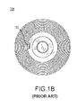
- FIG. 1B a longitudinal perspective view of a conventional ball nut 104 (looking from A to A' toward a distal portion of the ball nut 104 along the longitudinal axis A-A') is shown.
- This ball nut 104 includes a concentrically situated projection 110 or "tooth,” located at a distal portion of the ball nut 104.
- FIG. 1C a longitudinal perspective view of a distal portion of a conventional ball screw 106 is shown.
- the ball screw 106 includes a concentrically situated projection 112 or tooth as well.
- This projection 112 like the projection 110, is situated at a distal portion of the ball screw 106.
- the ball nut 104 may translate proximally (and/or distally) along the axis A-A' until the projection 112 in the ball screw 106 rotates into contact with the projection 110 in the ball nut 104. As the projection 112 makes contact with the projection 110, the ball nut 104 may be halted in its proximal progress, even as the ball screw 106 may attempt to rotate in an effort to force the ball nut 104 proximally into a home stop or stowed position.
- the projection 112 may rotate with substantial angular momentum into the projection 110. As this occurs, the projection 112 and/or the projection 110 may chip or break. Failure of either projection 110 and/or 112 may result in expulsion of the entire ball nut 104 from its housing within the EMA housing 102, leaving the ball nut 104 (and/or other components) behind as litter and/or other dangerous debris. Such an event may, in addition, result in brake failure.
- a variety of disadvantages are associated with existing conventional systems.
- the EMA 200 may, like the EMA 100, comprise an EMA housing 202, a ball nut 204, a ball screw 206, an ADU housing 207, and a disc or puck 208.
- the EMA housing 200 may comprise a generally annular structure configured to house the ball nut 204 and extending along the axis A-A'.
- the ball nut 204 may comprise a generally annular housing that extends axially along the axis A-A' within the EMA housing 202.
- the ball screw 206 may comprise a generally annular housing that extends axially along the axis A-A' within the ball nut 204.
- the ADU housing 207 may comprise a generally annular housing that extends axially along the axis A-A' at least partially radially inward of the ball screw 206.
- a variety of drive components may be housed within the ADU housing 207, such as, for example, an electromechanical drive motor, drive shaft, gearing system, and the like.
- the puck 208 may comprise a generally disc shaped element, and the puck 208 may be coupled to a distal portion of the ball nut 204.
- the EMA 200 described herein may comprise an ADU housing 207 comprising a projection or stop 210 extending radially outward of the ADU housing 207.
- the stop 210 may extend radially outward such that it is raised above an outer surface of the ADU housing 207.
- the stop 210 may be disposed substantially at a proximal portion of the ADU housing 207 and may comprise a "T-shaped" or doglegged structure.
- a proximal portion of the stop 210 may incorporate a compliant or shock absorbing material, such as foam or rubber. This material may dissipate energy, as described below, as the ball nut 204 comes into contact with the stop 210.
- the stop 210 may be coupled to the ADU housing 207 in any suitable manner. For instance, the stop 210 may be screwed into the ADU housing 207, heat bonded to the ADU housing 207, forged integral to the ADU housing 207, riveted to the ADU housing 207, bolted into the ADU housing 207, adhesively bonded to the ADU housing 207, and the like.
- the ball nut 204 may come into contact with the stop 210.
- the proximal translation of the ball nut 204 may be halted.
- the stop 210 may however, unlike other conventional systems, resist or eliminate EMA 200 failure.
- the stop 210 comprising a continuous annular structure, may not rely upon one or more simple projections (e.g., projections 110 and 112) to arrest the angular momentum of the ball nut 104. Rather, the large (continuous) surface area of the stop 210 may permit the dissipation of angular and axial momentum over a much larger, surface area.
- Dissipation of angular and axial momentum over this larger surface area reduces the overall stress experienced by any particular portion of the ball nut 204 and/or ball screw 206 (e.g., the projections 110 and 112 in the conventional system), particularly as the ball nut 204 and/or the ADU housing 207 and/or stop 210 may be manufactured, for durability and strength, from steel or a steel alloy, such as, for example, a hardened steel.
- the system of the present disclosure therefore embodies a much more reliable, failure-resistant, ball nut 204 stopping system.
- the cost and weight of the system of the present disclosure may also be reduced over that associated with more conventional systems, as projections 110 and 112 may be eliminated in favor of the stop 210.
- a computer-based system comprising a processor and a tangible, non-transitory, memory coupled to the processor may track or count the number of motor rotations or revolutions as the ball nut 204 advances distally from the stop 210.
- This information in combination with a gear ratio and/or a distance of a portion of the ball nut 204 (e.g., the distal edge of the ball nut 204) from the stop 210 may permit the computer-based system to calculate the position of the ball nut 204 and/or the ball nut 204 actuating mechanism.
- the location of the ball nut 204 and/or actuator may be fed back into the computer-based system to control the advancement and/or retraction of the ball nut 204 during operation.
- references to "various embodiments”, “one embodiment”, “an embodiment”, “an example embodiment”, etc. indicate that the embodiment described may include a particular feature, structure, or characteristic, but every embodiment may not necessarily include the particular feature, structure, or characteristic. Moreover, such phrases are not necessarily referring to the same embodiment. Further, when a particular feature, structure, or characteristic is described in connection with an embodiment, it is submitted that it is within the knowledge of one skilled in the art to affect such feature, structure, or characteristic in connection with other embodiments whether or not explicitly described. After reading the description, it will be apparent to one skilled in the relevant art(s) how to implement the disclosure in alternative embodiments.
- non-transitory computer-readable medium should be construed to exclude only those types of transitory computer-readable media which were found in In re Nuijten, 500 F.3d 1346 (Fed. Cir. 2007) to fall outside the scope of patentable subject matter under 35 U.S.C. ⁇ 101, so long as and to the extent In re Nuijten remains binding authority in the U.S. federal courts and is not overruled by a future case or statute. Stated another way, the term “computer-readable medium” should be construed in a manner that is as broad as legally permissible.
Abstract
Description
- The present disclosure relates to electromechanical actuators ("EMAs"), and more particularly, to a stopping assembly for EMAs.
- EMAs are braking assemblies that forcefully move a translating member (such as a "ball nut") against a brake disk stack to generate an actuation force. This actuation force drives the ball nut into forceful engagement with the brake disk stack to generate a braking force.
- An electromechanical actuator (EMA) is disclosed. The EMA may comprise an EMA housing, a ball nut extending axially within the EMA housing, a ball screw extending axially within the ball nut, and/or an actuator drive unit (ADU) housing extending axially within the ball screw, the ADU housing having a proximal stop that extends radially outward of the ADU housing. The ball nut may be configured to translate axially in a proximal direction in response to a rotation by the ball screw, and the ball nut may be configured to be halted in the axially proximal translation in response to contact with the proximal stop. The proximal stop may be coupled to the ADU housing. The proximal stop may comprise a continuous annular structure. The ball nut may make contact with the proximal stop as the ball nut translates axially to halt the axially proximal translation of the ball nut. The proximal stop may include a compliant surface. The ball nut may be configured to advance axially in a distal direction away from the proximal stop and/or to retract axially in the proximal direction towards the proximal stop. A position of the ball nut may be determined based upon a gear ratio.
- An EMA is disclosed. The EMA may comprise an EMA housing, a ball nut extending axially within the EMA housing, and/or an ADU housing disposed radially inward of the ball nut, the ADU housing having a proximal stop that extends radially outward of the ADU housing, ball nut being configured to translate axially in a proximal direction and to be halted in the axially proximal translation in response to contact with the proximal stop. The proximal stop may be coupled to the ADU housing. The proximal stop may comprise a continuous annular structure. The ball nut may make contact with the proximal stop as the ball nut translates axially to halt the axially proximal translation of the ball nut. The proximal stop may include a compliant surface. The ball nut may be configured to advance axially in a distal direction away from the proximal stop. The ball nut may be configured to retract axially in the proximal direction towards the proximal stop.
- The subject matter of the present disclosure is particularly pointed out and distinctly claimed in the concluding portion of the specification. A more complete understanding of the present disclosure, however, may best be obtained by referring to the detailed description and claims when considered in connection with the drawing figures, wherein like numerals denote like elements.
-
Figure. 1A illustrates a cross-sectional schematic view of a conventional EMA; -
Figure. 1B illustrates top perspective view of a conventional ball nut; -
Figure 1C illustrates a top perspective view of a conventional ball screw; -
Figure. 2A illustrates, in accordance with various embodiments, a cross-sectional schematic view of an EMA; and -
Figure 2B illustrates, in accordance with various embodiments, a partial cross-sectional schematic view of an EMA. - The detailed description of exemplary embodiments herein makes reference to the accompanying drawings, which show exemplary embodiments by way of illustration and their best mode. While these exemplary embodiments are described in sufficient detail to enable those skilled in the art to practice the inventions, it should be understood that other embodiments may be realized and that logical, chemical and mechanical changes may be made without departing from the scope of the inventions. Thus, the detailed description herein is presented for purposes of illustration only and not of limitation. For example, the steps recited in any of the method or process descriptions may be executed in any order and are not necessarily limited to the order presented. Furthermore, any reference to singular includes plural embodiments, and any reference to more than one component or step may include a singular embodiment or step. Also, any reference to attached, fixed, connected or the like may include permanent, removable, temporary, partial, full and/or any other possible attachment option. Additionally, any reference to without contact (or similar phrases) may also include reduced contact or minimal contact.
- As used herein, an "inner surface" may comprise any surface that is situated radially inward of any other surface with respect to the axis, as defined herein, labeled A-A'. Thus, an inner surface may be situated radially inward of an "outer surface" with respect to the axis A-A'.
- In addition, the EMA may extend along the axis defined by the line marked A-A'. The portion near A may be referred to as proximal and the portion near A' may be referred to as distal. In that regard, A is proximal to A' and A' is distal to A. Translation in an axial direction towards A is considered movement in a proximal direction and translation in an axial direction towards A' is considered movement in a distal direction.
- With reference to
Figure 1A , a cross-sectional schematic view of aconventional EMA 100 is shown. The EMA 100 may comprise an EMAhousing 102, an actuator drive unit ("ADU")housing 111, aball nut 104, aball screw 106, and a disc or "puck" 108. The EMAhousing 100 may comprise a generally annular structure configured to house theball nut 104 and extending along the axis A-A'. Theball nut 104 may comprise a generally annular housing that extends axially along the axis A-A' within the EMAhousing 102. Theball screw 106 may comprise a generally annular housing that extends axially along the axis A'A' within theball nut 104. The ADUhousing 111 may comprise a generally annular housing that extends axially along the axis A-A' at least partially radially inward of theball screw 106. A variety of drive components may be housed within the ADUhousing 111, such as, for example, an electromechanical drive motor, drive shaft, gearing system, and the like. The ADUhousing 111 may comprise a stationary (non-rotating, non-translating) component. Thepuck 108 may comprise a generally disc shaped element, and thepuck 108 may be coupled to a distal portion of theball nut 104. - An inner surface of the
ball nut 104 may be helically threaded. Likewise, an outer surface of theball screw 106 may be helically threaded. As described above, theball screw 106 may be housed within theball nut 104, and the threading on the outer surface of theball screw 106 may interface with or mate with the threading on the inner surface of theball nut 104. - During operation, the
ball screw 106 may rotate about an axis A-A'. As theball screw 106 rotates, the threading on theball screw 106 may cooperate with the threading in theball nut 104 to drive theball nut 104 in a distal direction. As theball nut 104 translates distally, thepuck 108 coupled to theball nut 104 may also translate distally. Thepuck 108 may contact a brake stack (e.g., a brake stack associated with an aircraft wheel) to apply force to the brake stack, thereby slowing and/or halting the rotation of the aircraft wheel. - With reference to
Figure 1B , a longitudinal perspective view of a conventional ball nut 104 (looking from A to A' toward a distal portion of theball nut 104 along the longitudinal axis A-A') is shown. Thisball nut 104 includes a concentricallysituated projection 110 or "tooth," located at a distal portion of theball nut 104. - With reference to
Figure 1C , a longitudinal perspective view of a distal portion of aconventional ball screw 106 is shown. Theball screw 106 includes a concentrically situatedprojection 112 or tooth as well. Thisprojection 112, like theprojection 110, is situated at a distal portion of theball screw 106. - In operation, as described above, as the
ball screw 106 rotates, theball nut 104 may translate proximally (and/or distally) along the axis A-A' until theprojection 112 in theball screw 106 rotates into contact with theprojection 110 in theball nut 104. As theprojection 112 makes contact with theprojection 110, theball nut 104 may be halted in its proximal progress, even as theball screw 106 may attempt to rotate in an effort to force theball nut 104 proximally into a home stop or stowed position. - A variety of disadvantages are associated with the conventional system depicted at
Figures 1A-1C . For example, theprojection 112 may rotate with substantial angular momentum into theprojection 110. As this occurs, theprojection 112 and/or theprojection 110 may chip or break. Failure of eitherprojection 110 and/or 112 may result in expulsion of theentire ball nut 104 from its housing within theEMA housing 102, leaving the ball nut 104 (and/or other components) behind as litter and/or other dangerous debris. Such an event may, in addition, result in brake failure. Thus, a variety of disadvantages are associated with existing conventional systems. - Now, with reference to
Figure 2A , anEMA 200 is shown. TheEMA 200 may, like theEMA 100, comprise anEMA housing 202, aball nut 204, aball screw 206, anADU housing 207, and a disc orpuck 208. As above, theEMA housing 200 may comprise a generally annular structure configured to house theball nut 204 and extending along the axis A-A'. Theball nut 204 may comprise a generally annular housing that extends axially along the axis A-A' within theEMA housing 202. Theball screw 206 may comprise a generally annular housing that extends axially along the axis A-A' within theball nut 204. TheADU housing 207 may comprise a generally annular housing that extends axially along the axis A-A' at least partially radially inward of theball screw 206. A variety of drive components may be housed within theADU housing 207, such as, for example, an electromechanical drive motor, drive shaft, gearing system, and the like. Thepuck 208 may comprise a generally disc shaped element, and thepuck 208 may be coupled to a distal portion of theball nut 204. - However, as shown in greater detail at
Figure 2B , theEMA 200 described herein may comprise anADU housing 207 comprising a projection or stop 210 extending radially outward of theADU housing 207. Thestop 210 may extend radially outward such that it is raised above an outer surface of theADU housing 207. In addition, thestop 210 may be disposed substantially at a proximal portion of theADU housing 207 and may comprise a "T-shaped" or doglegged structure. - A proximal portion of the
stop 210 may incorporate a compliant or shock absorbing material, such as foam or rubber. This material may dissipate energy, as described below, as theball nut 204 comes into contact with thestop 210. Thestop 210 may be coupled to theADU housing 207 in any suitable manner. For instance, thestop 210 may be screwed into theADU housing 207, heat bonded to theADU housing 207, forged integral to theADU housing 207, riveted to theADU housing 207, bolted into theADU housing 207, adhesively bonded to theADU housing 207, and the like. - In operation, as the
ball nut 204 translates axially in a proximal direction, theball nut 204 may come into contact with thestop 210. As theball nut 204 comes into contact with thestop 210, the proximal translation of theball nut 204 may be halted. Thestop 210 may however, unlike other conventional systems, resist or eliminateEMA 200 failure. For example, thestop 210, comprising a continuous annular structure, may not rely upon one or more simple projections (e.g.,projections 110 and 112) to arrest the angular momentum of theball nut 104. Rather, the large (continuous) surface area of thestop 210 may permit the dissipation of angular and axial momentum over a much larger, surface area. - Dissipation of angular and axial momentum over this larger surface area reduces the overall stress experienced by any particular portion of the
ball nut 204 and/or ball screw 206 (e.g., theprojections ball nut 204 and/or theADU housing 207 and/or stop 210 may be manufactured, for durability and strength, from steel or a steel alloy, such as, for example, a hardened steel. The system of the present disclosure therefore embodies a much more reliable, failure-resistant,ball nut 204 stopping system. The cost and weight of the system of the present disclosure may also be reduced over that associated with more conventional systems, asprojections stop 210. - In various embodiments, from the
stop 210, a computer-based system comprising a processor and a tangible, non-transitory, memory coupled to the processor may track or count the number of motor rotations or revolutions as theball nut 204 advances distally from thestop 210. This information, in combination with a gear ratio and/or a distance of a portion of the ball nut 204 (e.g., the distal edge of the ball nut 204) from thestop 210 may permit the computer-based system to calculate the position of theball nut 204 and/or theball nut 204 actuating mechanism. The location of theball nut 204 and/or actuator may be fed back into the computer-based system to control the advancement and/or retraction of theball nut 204 during operation. - Benefits, other advantages, and solutions to problems have been described herein with regard to specific embodiments. Furthermore, the connecting lines shown in the various figures contained herein are intended to represent exemplary functional relationships and/or physical couplings between the various elements. It should be noted that many alternative or additional functional relationships or physical connections may be present in a practical system. However, the benefits, advantages, solutions to problems, and any elements that may cause any benefit, advantage, or solution to occur or become more pronounced are not to be construed as critical, required, or essential features or elements of the inventions. The scope of the inventions is accordingly to be limited by nothing other than the appended claims, in which reference to an element in the singular is not intended to mean "one and only one" unless explicitly so stated, but rather "one or more."
- Systems, methods and apparatus are provided herein. In the detailed description herein, references to "various embodiments", "one embodiment", "an embodiment", "an example embodiment", etc., indicate that the embodiment described may include a particular feature, structure, or characteristic, but every embodiment may not necessarily include the particular feature, structure, or characteristic. Moreover, such phrases are not necessarily referring to the same embodiment. Further, when a particular feature, structure, or characteristic is described in connection with an embodiment, it is submitted that it is within the knowledge of one skilled in the art to affect such feature, structure, or characteristic in connection with other embodiments whether or not explicitly described. After reading the description, it will be apparent to one skilled in the relevant art(s) how to implement the disclosure in alternative embodiments.
- As used herein, the meaning of the term "non-transitory computer-readable medium" should be construed to exclude only those types of transitory computer-readable media which were found in In re Nuijten, 500 F.3d 1346 (Fed. Cir. 2007) to fall outside the scope of patentable subject matter under 35 U.S.C. § 101, so long as and to the extent In re Nuijten remains binding authority in the U.S. federal courts and is not overruled by a future case or statute. Stated another way, the term "computer-readable medium" should be construed in a manner that is as broad as legally permissible.
- Furthermore, no element, component, or method step in the present disclosure is intended to be dedicated to the public regardless of whether the element, component, or method step is explicitly recited in the claims. No claim element herein is to be construed under the provisions of 35 U.S.C. 112(f) unless the element is expressly recited using the phrase "means for." As used herein, the terms "comprises", "comprising", or any other variation thereof, are intended to cover a non-exclusive inclusion, such that a process, method, article, or apparatus that comprises a list of elements does not include only those elements but may include other elements not expressly listed or inherent to such process, method, article, or apparatus.
Claims (9)
- An electromechanical actuator (EMA) (200) comprising:an EMA housing (202);a ball nut (204) extending axially within the EMA housing (202); andan actuator drive unit (ADU) housing (207) disposed radially inward of the ball nut, the ADU housing (207) having a proximal stop (210) that extends radially outward of the ADU housing (207);
wherein the ball nut (204) is configured to translate axially in a proximal direction, and
wherein the ball nut (204) is configured to be halted in the axially proximal translation in response to contact with the proximal stop (210). - The EMA of claim 1, further comprising a ball screw (206) extending axially within the ball nut (204), wherein the ADU housing (207) extends axially within the ball screw (206), and wherein the ball nut (204) translates axially in the proximal direction in response to a rotation by the ball screw (206).
- The EMA of claim 1 or 2, wherein the proximal stop (210) is coupled to the ADU housing (207).
- The EMA of claim 1, 2 or 3, wherein the proximal stop (210) comprises a continuous annular structure.
- The EMA of any preceding claim, wherein the ball nut (204) makes contact with the proximal stop (210) as the ball nut (204) translates axially to halt the axially proximal translation of the ball nut (204).
- The EMA of any preceding claim, wherein the proximal stop (210) includes a compliant surface.
- The EMA of any preceding claim, wherein the ball nut (204) is configured to advance axially in a distal direction away from the proximal stop (210).
- The EMA of any preceding claim, wherein the ball nut (204) is configured to retract axially in the proximal direction towards the proximal stop (210).
- The EMA of any preceding claim, wherein a position of the ball nut (204) is determined based upon a gear ratio.
Applications Claiming Priority (1)
| Application Number | Priority Date | Filing Date | Title |
|---|---|---|---|
| US14/069,189 US9638300B2 (en) | 2013-10-31 | 2013-10-31 | Electromechanical actuator proximal position stopping assembly |
Publications (2)
| Publication Number | Publication Date |
|---|---|
| EP2891829A2 true EP2891829A2 (en) | 2015-07-08 |
| EP2891829A3 EP2891829A3 (en) | 2016-04-13 |
Family
ID=51951550
Family Applications (1)
| Application Number | Title | Priority Date | Filing Date |
|---|---|---|---|
| EP14191165.1A Pending EP2891829A3 (en) | 2013-10-31 | 2014-10-30 | Electromechanical actuator proximal position stopping assembly |
Country Status (2)
| Country | Link |
|---|---|
| US (1) | US9638300B2 (en) |
| EP (1) | EP2891829A3 (en) |
Families Citing this family (4)
| Publication number | Priority date | Publication date | Assignee | Title |
|---|---|---|---|---|
| DE102015208217A1 (en) * | 2015-05-04 | 2016-11-10 | Stabilus Gmbh | Threaded assembly and seat assembly with a threaded assembly |
| US9933059B2 (en) * | 2015-07-06 | 2018-04-03 | Goodrich Corporation | Dual-rate linear actuator |
| US10830321B2 (en) * | 2016-02-19 | 2020-11-10 | Goodrich Corporation | Actuator ball screw for improved load sharing |
| US10106139B2 (en) | 2017-02-02 | 2018-10-23 | Goodrich Corporation | Brake systems and methods |
Family Cites Families (9)
| Publication number | Priority date | Publication date | Assignee | Title |
|---|---|---|---|---|
| NL1006540C2 (en) * | 1997-07-10 | 1999-01-15 | Skf Ind Trading & Dev | Electric actuator with control sensor, as well as disc brake comprising such an actuator. |
| EP1050098B1 (en) * | 1998-01-20 | 2003-01-02 | SKF Engineering & Research Centre B.V. | Modular actuator, and brake calliper comprising such actuator |
| NL1011142C2 (en) * | 1999-01-27 | 2000-07-31 | Skf Eng & Res Centre Bv | Compact actuator. |
| US6139460A (en) * | 1999-05-24 | 2000-10-31 | Delphi Technologies, Inc. | Electric caliper |
| US6367593B1 (en) * | 2001-08-22 | 2002-04-09 | Delphi Technologies, Inc. | Electric caliper having splined ball screw |
| FR2848171B1 (en) | 2002-12-10 | 2005-10-28 | Delphi Tech Inc | METHOD FOR CONTROLLING AN ELECTRIC BRAKE CALIPER OF A MOTOR VEHICLE, PROGRAM COMPUTER AND BRAKE SYSTEM THEREFOR |
| US20040200676A1 (en) * | 2003-04-08 | 2004-10-14 | Huang-Tsang Chang | Electric sliding disc brake system |
| US20070029142A1 (en) | 2005-08-03 | 2007-02-08 | Drennen David B | Brake system including ball screw and nut assembly |
| US8109165B2 (en) * | 2009-09-29 | 2012-02-07 | Hamilton Sundstrand Corporation | Compliant non-jamming end of travel stop for a ball screw actuator |
-
2013
- 2013-10-31 US US14/069,189 patent/US9638300B2/en active Active
-
2014
- 2014-10-30 EP EP14191165.1A patent/EP2891829A3/en active Pending
Non-Patent Citations (1)
| Title |
|---|
| None |
Also Published As
| Publication number | Publication date |
|---|---|
| US20150114150A1 (en) | 2015-04-30 |
| US9638300B2 (en) | 2017-05-02 |
| EP2891829A3 (en) | 2016-04-13 |
Similar Documents
| Publication | Publication Date | Title |
|---|---|---|
| EP2891829A2 (en) | Electromechanical actuator proximal position stopping assembly | |
| US9527584B2 (en) | Electromechanically actuated brake with supplemental back drive | |
| CA2700572C (en) | Motorized spindle drive with overload protection | |
| US20110132704A1 (en) | Brake actuator assembly with line replaceable motor features | |
| US9933059B2 (en) | Dual-rate linear actuator | |
| EP2842821B1 (en) | electromechanical actuator with multi-row ball screw integrated in the drive unit housing and ball screw with a ball screw raceway on an inner surface of a cylindrical member | |
| US10578198B2 (en) | Ball screw assembly for aircraft brake | |
| EP2891830B1 (en) | Electromechanical actuator distal position stopping assembly | |
| EP2916043A2 (en) | Screw-type linear actuator including a torsion rod with bidirectional stop | |
| EP2965987A1 (en) | Belt park brake and method | |
| EP3045361B1 (en) | Bi-stable voice coil park brake | |
| US9308990B2 (en) | Voice coil linear activated park brake | |
| EP3020999B1 (en) | Aircraft brake puck assembly | |
| EP2573418B1 (en) | Actuator system and method | |
| EP2842822A2 (en) | Electromechanical actuator | |
| EP3426940B1 (en) | A brake for an actuator of an industrial robot | |
| EP2727780B1 (en) | Damping end-stop of electric braking apparatus | |
| WO2005015044A1 (en) | Brakes |
Legal Events
| Date | Code | Title | Description |
|---|---|---|---|
| PUAI | Public reference made under article 153(3) epc to a published international application that has entered the european phase |
Free format text: ORIGINAL CODE: 0009012 |
|
| 17P | Request for examination filed |
Effective date: 20141030 |
|
| AK | Designated contracting states |
Kind code of ref document: A2 Designated state(s): AL AT BE BG CH CY CZ DE DK EE ES FI FR GB GR HR HU IE IS IT LI LT LU LV MC MK MT NL NO PL PT RO RS SE SI SK SM TR |
|
| AX | Request for extension of the european patent |
Extension state: BA ME |
|
| PUAL | Search report despatched |
Free format text: ORIGINAL CODE: 0009013 |
|
| AK | Designated contracting states |
Kind code of ref document: A3 Designated state(s): AL AT BE BG CH CY CZ DE DK EE ES FI FR GB GR HR HU IE IS IT LI LT LU LV MC MK MT NL NO PL PT RO RS SE SI SK SM TR |
|
| AX | Request for extension of the european patent |
Extension state: BA ME |
|
| RIC1 | Information provided on ipc code assigned before grant |
Ipc: F16H 25/22 20060101AFI20160309BHEP Ipc: H02K 7/116 20060101ALI20160309BHEP |
|
| R17P | Request for examination filed (corrected) |
Effective date: 20161013 |
|
| RBV | Designated contracting states (corrected) |
Designated state(s): AL AT BE BG CH CY CZ DE DK EE ES FI FR GB GR HR HU IE IS IT LI LT LU LV MC MK MT NL NO PL PT RO RS SE SI SK SM TR |
|
| STAA | Information on the status of an ep patent application or granted ep patent |
Free format text: STATUS: EXAMINATION IS IN PROGRESS |
|
| 17Q | First examination report despatched |
Effective date: 20200218 |
|
| STAA | Information on the status of an ep patent application or granted ep patent |
Free format text: STATUS: EXAMINATION IS IN PROGRESS |
|
| STAA | Information on the status of an ep patent application or granted ep patent |
Free format text: STATUS: EXAMINATION IS IN PROGRESS |
|
| P01 | Opt-out of the competence of the unified patent court (upc) registered |
Effective date: 20230922 |