EP2891827A2 - Electromechanically actuated decoupling device for actuators - Google Patents
Electromechanically actuated decoupling device for actuators Download PDFInfo
- Publication number
- EP2891827A2 EP2891827A2 EP13004215.3A EP13004215A EP2891827A2 EP 2891827 A2 EP2891827 A2 EP 2891827A2 EP 13004215 A EP13004215 A EP 13004215A EP 2891827 A2 EP2891827 A2 EP 2891827A2
- Authority
- EP
- European Patent Office
- Prior art keywords
- actuator
- drive
- actuator element
- ball screw
- elements
- Prior art date
- Legal status (The legal status is an assumption and is not a legal conclusion. Google has not performed a legal analysis and makes no representation as to the accuracy of the status listed.)
- Granted
Links
- 230000008859 change Effects 0.000 claims description 31
- 230000033001 locomotion Effects 0.000 claims description 16
- 230000007246 mechanism Effects 0.000 claims description 16
- 238000012360 testing method Methods 0.000 claims description 16
- 230000007547 defect Effects 0.000 claims description 14
- 238000013519 translation Methods 0.000 claims description 10
- 238000007789 sealing Methods 0.000 claims description 9
- 239000000314 lubricant Substances 0.000 claims description 8
- 230000000694 effects Effects 0.000 claims description 4
- 238000005516 engineering process Methods 0.000 abstract description 4
- 230000007257 malfunction Effects 0.000 abstract description 2
- 230000005540 biological transmission Effects 0.000 description 18
- 230000002950 deficient Effects 0.000 description 5
- 230000002441 reversible effect Effects 0.000 description 5
- 238000010168 coupling process Methods 0.000 description 4
- 238000005859 coupling reaction Methods 0.000 description 4
- 230000000903 blocking effect Effects 0.000 description 3
- 230000008878 coupling Effects 0.000 description 3
- 238000013461 design Methods 0.000 description 3
- 238000005461 lubrication Methods 0.000 description 3
- 238000004904 shortening Methods 0.000 description 3
- 230000001050 lubricating effect Effects 0.000 description 2
- 230000009347 mechanical transmission Effects 0.000 description 2
- 230000003068 static effect Effects 0.000 description 2
- RZVHIXYEVGDQDX-UHFFFAOYSA-N 9,10-anthraquinone Chemical compound C1=CC=C2C(=O)C3=CC=CC=C3C(=O)C2=C1 RZVHIXYEVGDQDX-UHFFFAOYSA-N 0.000 description 1
- 230000009471 action Effects 0.000 description 1
- 230000032683 aging Effects 0.000 description 1
- 230000015572 biosynthetic process Effects 0.000 description 1
- UQMRAFJOBWOFNS-UHFFFAOYSA-N butyl 2-(2,4-dichlorophenoxy)acetate Chemical compound CCCCOC(=O)COC1=CC=C(Cl)C=C1Cl UQMRAFJOBWOFNS-UHFFFAOYSA-N 0.000 description 1
- 238000000576 coating method Methods 0.000 description 1
- 125000004122 cyclic group Chemical group 0.000 description 1
- 238000013016 damping Methods 0.000 description 1
- 230000001419 dependent effect Effects 0.000 description 1
- 239000004519 grease Substances 0.000 description 1
- 230000002427 irreversible effect Effects 0.000 description 1
- 239000000463 material Substances 0.000 description 1
- 238000000034 method Methods 0.000 description 1
- 238000012544 monitoring process Methods 0.000 description 1
- 239000002245 particle Substances 0.000 description 1
- 229920001296 polysiloxane Polymers 0.000 description 1
- 238000004321 preservation Methods 0.000 description 1
- 230000008569 process Effects 0.000 description 1
- 230000009467 reduction Effects 0.000 description 1
- 238000005096 rolling process Methods 0.000 description 1
- 238000004088 simulation Methods 0.000 description 1
- 239000007787 solid Substances 0.000 description 1
- 230000001960 triggered effect Effects 0.000 description 1
Images


Classifications
-
- F—MECHANICAL ENGINEERING; LIGHTING; HEATING; WEAPONS; BLASTING
- F16—ENGINEERING ELEMENTS AND UNITS; GENERAL MEASURES FOR PRODUCING AND MAINTAINING EFFECTIVE FUNCTIONING OF MACHINES OR INSTALLATIONS; THERMAL INSULATION IN GENERAL
- F16H—GEARING
- F16H25/00—Gearings comprising primarily only cams, cam-followers and screw-and-nut mechanisms
- F16H25/18—Gearings comprising primarily only cams, cam-followers and screw-and-nut mechanisms for conveying or interconverting oscillating or reciprocating motions
- F16H25/20—Screw mechanisms
- F16H25/205—Screw mechanisms comprising alternate power paths, e.g. for fail safe back-up
-
- B—PERFORMING OPERATIONS; TRANSPORTING
- B64—AIRCRAFT; AVIATION; COSMONAUTICS
- B64C—AEROPLANES; HELICOPTERS
- B64C13/00—Control systems or transmitting systems for actuating flying-control surfaces, lift-increasing flaps, air brakes, or spoilers
- B64C13/24—Transmitting means
- B64C13/26—Transmitting means without power amplification or where power amplification is irrelevant
- B64C13/28—Transmitting means without power amplification or where power amplification is irrelevant mechanical
- B64C13/341—Transmitting means without power amplification or where power amplification is irrelevant mechanical having duplication or stand-by provisions
-
- B—PERFORMING OPERATIONS; TRANSPORTING
- B64—AIRCRAFT; AVIATION; COSMONAUTICS
- B64C—AEROPLANES; HELICOPTERS
- B64C13/00—Control systems or transmitting systems for actuating flying-control surfaces, lift-increasing flaps, air brakes, or spoilers
- B64C13/24—Transmitting means
- B64C13/38—Transmitting means with power amplification
- B64C13/50—Transmitting means with power amplification using electrical energy
- B64C13/505—Transmitting means with power amplification using electrical energy having duplication or stand-by provisions
-
- F—MECHANICAL ENGINEERING; LIGHTING; HEATING; WEAPONS; BLASTING
- F16—ENGINEERING ELEMENTS AND UNITS; GENERAL MEASURES FOR PRODUCING AND MAINTAINING EFFECTIVE FUNCTIONING OF MACHINES OR INSTALLATIONS; THERMAL INSULATION IN GENERAL
- F16H—GEARING
- F16H25/00—Gearings comprising primarily only cams, cam-followers and screw-and-nut mechanisms
- F16H25/18—Gearings comprising primarily only cams, cam-followers and screw-and-nut mechanisms for conveying or interconverting oscillating or reciprocating motions
- F16H25/20—Screw mechanisms
- F16H25/22—Screw mechanisms with balls, rollers, or similar members between the co-operating parts; Elements essential to the use of such members
- F16H25/2204—Screw mechanisms with balls, rollers, or similar members between the co-operating parts; Elements essential to the use of such members with balls
-
- F—MECHANICAL ENGINEERING; LIGHTING; HEATING; WEAPONS; BLASTING
- F16—ENGINEERING ELEMENTS AND UNITS; GENERAL MEASURES FOR PRODUCING AND MAINTAINING EFFECTIVE FUNCTIONING OF MACHINES OR INSTALLATIONS; THERMAL INSULATION IN GENERAL
- F16H—GEARING
- F16H25/00—Gearings comprising primarily only cams, cam-followers and screw-and-nut mechanisms
- F16H25/18—Gearings comprising primarily only cams, cam-followers and screw-and-nut mechanisms for conveying or interconverting oscillating or reciprocating motions
- F16H25/20—Screw mechanisms
- F16H2025/2062—Arrangements for driving the actuator
- F16H2025/2071—Disconnecting drive source from the actuator, e.g. using clutches for release of drive connection during manual control
-
- F—MECHANICAL ENGINEERING; LIGHTING; HEATING; WEAPONS; BLASTING
- F16—ENGINEERING ELEMENTS AND UNITS; GENERAL MEASURES FOR PRODUCING AND MAINTAINING EFFECTIVE FUNCTIONING OF MACHINES OR INSTALLATIONS; THERMAL INSULATION IN GENERAL
- F16H—GEARING
- F16H25/00—Gearings comprising primarily only cams, cam-followers and screw-and-nut mechanisms
- F16H25/18—Gearings comprising primarily only cams, cam-followers and screw-and-nut mechanisms for conveying or interconverting oscillating or reciprocating motions
- F16H25/20—Screw mechanisms
- F16H2025/2062—Arrangements for driving the actuator
- F16H2025/2081—Parallel arrangement of drive motor to screw axis
-
- Y—GENERAL TAGGING OF NEW TECHNOLOGICAL DEVELOPMENTS; GENERAL TAGGING OF CROSS-SECTIONAL TECHNOLOGIES SPANNING OVER SEVERAL SECTIONS OF THE IPC; TECHNICAL SUBJECTS COVERED BY FORMER USPC CROSS-REFERENCE ART COLLECTIONS [XRACs] AND DIGESTS
- Y02—TECHNOLOGIES OR APPLICATIONS FOR MITIGATION OR ADAPTATION AGAINST CLIMATE CHANGE
- Y02T—CLIMATE CHANGE MITIGATION TECHNOLOGIES RELATED TO TRANSPORTATION
- Y02T50/00—Aeronautics or air transport
- Y02T50/40—Weight reduction
Definitions
- the present invention relates to aircraft technology.
- the present invention relates to actuator technology for aerodynamically effective elements of an aircraft.
- the present invention relates to an actuator element with a reversible decoupling device, an actuator assembly and an aircraft, in particular aircraft or helicopter.
- Actuators are used in aircraft to mechanically move elements of the aircraft and to change their position or position.
- these are, for example, rudder surfaces or elements of the wings in order to influence the buoyancy behavior of the aircraft. In helicopters this may for example affect the different rotor blade adjustment by a swash plate.
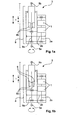
- FIG. 1a shows a schematic representation of an electromechanical actuator.
- two motor elements 1 are connected to the drive unit 8 of the actuator element 3 using a suitable connection consisting of motor shaft 2 a and a suitable transmission 2 b.
- the drive unit 8 is variable in its length I, in particular in its distance between the two connection points 5a, b, so that a change in length of the drive unit 8 of the actuator 3, the distance between the connection points 5a, b changed.
- a suitable clamping between elements it is thus possible, for example, to move or tilt, for example, an aerodynamically effective structure.
- the drive unit 8 consists of a first drive element 8a and a second drive element 8b, for example constructed as a ball screw 8 with ball screw nut 8b and ball screw 8a.
- the ball screw nut 8b By a rotation of the ball screw 8a, the ball screw nut 8b is slidable on this, so that the rotation of the ball screw 8a a change in length of the drive unit 8 and thus the actuator element 3 or a change in the distance between the connection points 5a, b provides.
- a defect of an actuator element in particular in mission-critical aerodynamically effective surfaces, it must be ensured that they can at least continue to be moved in spite of the defect.
- a certain redundancy is usually provided, depending on the specific application.
- a second actuator element may be arranged in a force-parallel manner to the first, so that the change in position of the aerodynamically effective surface of a the two or even from both actuator elements can be perceived together.
- an actuator element of the two parallel actuator elements now fails, the other one can at least maintain the function.
- defects of actuator elements which subsequently no longer make it possible to carry out a change in length;
- the breakage of a ball of the ball screw can possibly block the ball screw and the ball screw nut against each other, so that a change in length of the actuator is no longer possible.
- control of the aerodynamically effective area can not be performed by the parallel arranged actuator element.
- the aircraft would no longer be controllable and would possibly crash.
- decoupling devices or decoupling mechanisms can be integrated into the actuator elements, which in an error situation cancel the blockage by decoupling the blocked actuator element and thereby ensure it in that the aerodynamically effective surface remains movable and controllable by the action of force of the element arranged in parallel.
- Figure 1 b shows an exemplary embodiment of such actuator element.
- Decoupling device 6 not only decouples the two drive elements 8a, b from each other, but decoupling is made such that a decoupling of the attack points 5a, b takes place, wherein one of the attack points also in the decoupled state is substantially connected to both drive elements of the drive unit, while the connection of a drive element to the second point 5b is released. This may cause the Change length of an actuator independently of whether a mechanism of the drive unit, for example, the first drive element 8a to the second drive element 8b is blocked.
- One aspect of the present invention may be seen to provide a particular embodiment of a reversible decoupling device for an electromechanical actuator element.
- an actuator element comprising a drive unit having a first drive element and a second drive element, wherein the first drive element and the second drive element functionally cooperate in such a way to effect a change in length of the actuator element, wherein the actuator element has a decoupling device wherein the actuator element has two connection points whose distance can be determined by the change in length of the actuator, wherein one of the drive elements is connected substantially wirkunffenbar with one of the connection points, wherein the actuator element has an output piston which is connected substantially wirkunffenbar with the other of the connection points , wherein the distance of the two connection points in the coupled state of the decoupling device is adjustable by the actuator element and wherein the distance between the two connection points i m decoupled state of the decoupling device by a force applied to the connection points from the outside is changeable.
- the decoupling device has a decoupling mechanism with a drive element, a form-fitting element and a holding element, wherein the holding element is arranged to assume a first position, in which the positive-locking element is in a closed state, and wherein the holding element is adapted to assume a second position, in which the positive-locking element is in an open state.
- the drive element is configured to displace the holding element between the first position and the second position, whereby the positive connection of the form-locking element is reversibly detachable and fixable, wherein the decoupling functionally decouples the output piston from a drive element of the actuator, so that the change in length of the actuator element regardless the drive unit is made possible, in particular without functional decoupling of the first drive element and the second drive element.
- an actuator arrangement is shown with at least two actuator elements according to the present invention, wherein the at least two actuator elements are arranged in a force-parallel manner so that a change in length of the actuator arrangement can be effected in parallel by an actuator element alone or by both actuator elements.
- an aircraft in particular aircraft or helicopter, with an actuator assembly according to the present invention and / or an actuator element according to the present invention is displayed.
- Conventional actuator elements for the control of aerodynamically active elements either have no decoupling device or only one which possibly only provides irreversible decoupling or decoupling, which can only be coupled in again with an increased amount of work.
- electromechanical actuator elements with a decoupling device which control aerodynamically active elements, may, however, be mission-critical elements, which may possibly increase in the event of a fault cause a crash of the aircraft, is a regular test of a decoupling device, thus the simulation of the error case to ensure the correct operation in case of failure desirable.
- Electromechanical actuator elements, which can not be re-coupled with little effort thus may not be tested at regular intervals. This may not be ensured that a conventional decoupling device works properly in an emergency and thus ensures the preservation of the flying ability of an aircraft.
- an actuator element with a decoupling device is displayed, which can be converted into a coupled state after a release in a simple manner again.
- An actuator with such a reversible decoupling device may now be checked regularly for its correct functioning, for example during a detailed test before the operation of an aircraft.
- the decoupling device can thus be triggered under load, thus decoupling the actuator element, as a result of which the worst case scenario of flight operation may be readjusted.
- the still functional actuator element can simply be re-coupled, thereby providing its normal operation.
- Core of the present invention is the coupling of an output piston with a drive unit of the actuator element such that the output shaft is positively connected to a drive element of the drive unit.
- the drive unit has a first drive element and a second drive element, which functionally cooperate in such a way that a change in length of the actuator element can be provided by the drive unit.
- the two attachment points of an actuator element which ultimately represent the effective length of the actuator, can thus be arranged on the output piston on the one hand and on the other hand on the actuator itself, for example on its housing.
- a connection point is fixedly connected to the housing of the actuator, while the second connection point is connected via the output piston and connected to the drive unit above.
- the output piston is subject to a translational movement, whereby the actuator element is adjustable in its length.
- the output piston In decoupled state of the decoupling device, the output piston is now positively connected to the drive unit or a drive element of the same. In an error case or Entkoppelungsfall may now be solved the positive connection between the output piston and drive element of the drive unit.
- the actuator element may experience a decoupling of the drive unit and the output piston, so that the length of the actuator element can be adjusted from the outside by a comparatively small supply of force. In the event of an error, in which the actuator element is thus decoupled, this, despite its defect, does not constitute a blocked device which could possibly lead to a negative influence on the controllability of an aircraft.
- Such actuator elements are usually provided in the form of an actuator arrangement, which provides some redundancy for the control or positioning of aerodynamically active elements.
- two actuator elements can be arranged in a force-parallel or effective parallel manner, so that the position and orientation of the aerodynamically active element can be effected separately by each of the actuator elements or if they interact, whereby a force can be applied by the two actuator elements.
- the decoupling device In the event of a fault, ie in the event that one of the actuator elements has a defect and is no longer functional, in the worst case blocked, so that a change in length is no longer possible, the decoupling device according to the invention, the actuator element decouple such that a change in length of the actuator element by a force applied from the outside is effected.
- the defective actuator element could be decoupled and thus does not limit the controllability of the aerodynamically active element for the second actuator element arranged in parallel, apart from a slight expenditure of force for the change in length of the defective actuator element.
- the controllability of the aerodynamically effective surface can still be ensured despite the worst case blocking defect of one of the two active or parallel arranged actuator elements.
- the drive unit may be formed as a ball screw, wherein the first drive element and the second drive element may be formed as a ball screw and ball screw nut of the ball screw.
- the first drive element and the second drive element may be formed as a ball screw and ball screw nut of the ball screw.
- a ball screw drive consists of a spindle and a ball screw nut.
- Another embodiment provides to rotate the ball screw nut, while the ball screw thereby performs a translation parallel to the axis of rotation.
- the actuator element may further comprise a motor element, wherein the ball screw nut is rotatable using the motor element, whereby a change in length of the actuator element by translation of the ball screw is executable.
- the interlocking element may be brought into positive engagement with the output piston, so that the translation of the ball screw causes a translation of the output piston.
- the present invention relates to an embodiment in which the ball screw nut rotates while the ball screw spindle is translationally moved and the length of the actuator element is adjusted.
- the decoupling device should not, if possible, separate the drive elements themselves, since this may not be possible at all times, in particular in the case of a ball screw or planetary roller screw drive.
- a connection point is connected to the drive unit, the second connection point is connected via another element to the other drive element, while the decoupling device or the decoupling mechanism decouples a, in particular form-fitting, connection of drive element and further element with connection point such that a possibility of length change can be ensured by an external force on the actuator element in the decoupled state, even in the case of a complete blockage of the first drive element and the second drive element by separating the connection between the drive element and further element.
- the decoupling device or the decoupling mechanism is preferably displaceable between a first state, a closed state in which the positive-locking element is closed, and a second state, an open state in which the positive-locking element has a released positive connection.
- the spindle may be formed as a hollow spindle, wherein the output piston is arranged in the interior of the spindle.
- the actuator element of the present invention thus comprises a drive unit with a ball screw, in particular a rotating spindle nut, and a translationally moving spindle, on which an output piston using the decoupling mechanism is positively connected, wherein on the output piston of the second connection point is arranged.
- the spindle can be formed for example as a hollow spindle, in the interior of the output piston is arranged.
- the output piston may be substantially freely displaceable in the interior of the spindle, while the output piston in the form-closed state of the positive-locking element is fixedly connected to the spindle and moves translationally upon rotation of the spindle nut with the spindle. In form-locked state, the output piston can be moved with relatively little force in the interior of the spindle.
- the present invention may be provided in the first position of the holding element, a positive connection between the output piston and the spindle, while dissolved in the second position of the holding element of the positive connection between the output piston and the spindle and the output shaft in the interior of the spindle Essentially freely movable.
- the holding element together with the form-fitting element preferably do not act in the same direction of force, which may act on the actuator element due to elongation or shortening.
- a force of the holding element on the form-locking element for providing the positive connection substantially perpendicular to the force provided by the actuator element due to its elongation or shortening.
- the force provided by the holding element can be essentially limited to holding the positive locking and does not have to be designed to be so stable at the same time that it can withstand the force which the actuator element applies during elongation or shortening.
- the force of the holding element is decoupled from the force of the actuator.
- the form-locking element may be formed as a plurality of ball elements, wherein the output piston to the ball elements corresponding recesses, wherein the holding element is formed as a sleeve member having recesses, wherein the sleeve member using the drive element of the decoupling mechanism rotatable is, wherein the sleeve member is arranged in the first position to hold the ball elements in the recesses of the output piston to provide the positive connection between the output piston and spindle and wherein the sleeve member is arranged in the second position to receive the ball elements in the recesses of the sleeve member, so that the positive connection is solved.
- the interlocking elements can thus be offset between a first, form-closed position in which they are arranged in the recesses of the output piston, and a second, form-dissolved position in which they are arranged in the recesses of the sleeve member.
- the sleeve member may thus perform a relatively small rotation and pivot substantially between a position in which the recesses of the sleeve member are aligned with the interlocking elements, and a position in which the interlocking elements are pressed or held in the corresponding recesses of the output piston become.
- the actuator element further likes a housing and a sealing element arrangement have, wherein the sealing element arrangement is arranged such that the region of positive-locking element, retaining element, output piston and housing is formed substantially tight, so that in particular the area can be filled with a suitable lubricant.
- Such an arrangement may further reduce friction in the decoupling mechanism, so that the release force of the decoupling mechanism is comparatively low. Due to the dense configuration of the region of the sealing element arrangement, the latter may moreover be designed substantially maintenance-free.
- the actuator element may further comprise rod seals, wherein a sealing effect for the lubricant is provided substantially also during a test using the rod seals.
- connection points may be arranged at a housing end of the actuator, while the further connection point is arranged at the outer end of the output piston.
- the two connection points which form the effective length of the actuator element are arranged at opposite ends of the actuator element, while furthermore a simple decoupling of output pistons and elements provided in the actuator element, such as individual drive elements, can be provided by the decoupling device or the decoupling mechanism.
- the decoupling device may be decoupled in the course of a test and be coupled again after completion of the test.
- a cyclic function test with respect to the emergency decoupling of the actuator element is carried out be and in particular be ensured that the actuator element or its decoupling device can perform a decoupling in the event of a critical error during flight operations and not blocked.
- the decoupling device may trigger the Entkoppelungsmechanismus of the actuator in the event of a defect of a drive unit or the ball screw or Planetenrollengewindetriebs an actuator, so that the actuator is functionally decoupled, wherein the change in length of the actuator further effected by the non-decoupled actuator element is.
- the decoupling device according to the invention thus ensures that the displaceability of an actuator element from the outside is ensured even in case of failure, in the worst case in the blocking case of the first and second drive element to each other, so that the remaining, redundant, arranged in parallel second actuator element continue to set the aerodynamically active element can be influenced without being negatively influenced by the defective actuator element.
- a conductive connections between the decoupling device and an aircraft may be feasible exclusively for the stationary part of the decoupling device, so that a movement of the movable part of the decoupling device does not cause any mobility of the conductive connections. Due to the mechanical transmission of the rotation through the pivoting sleeve from the stationary to the movable part of the decoupling device or the element, all connections of the element, in particular including all connections of the decoupling device, respectively comprising connections for power transmission and transmission of sensor signals from / to the associated control / monitoring be mounted in the stationary part of the element. This eliminates the need for a special design of the wiring harness for compensation a possible relative movement, which would be associated with additional effort, cost and potentially reduced reliability.
- FIG. 2 a schematic representation of an electromechanical actuator according to the present invention is shown.
- FIG. 2 shows a schematic embodiment of an electromechanical actuator 3, for example, for controlling the primary flight control elements for helicopters.
- two motor elements 1 are provided which are connected using motor shaft 2a and suitable transmission 2b, c to the second drive element 8b, designed as a rotating ball screw nut of a ball screw drive.
- Actuator element 3 is changeable or adjustable in its length I, in particular between the two attachment points 5a, b, so that a change in length of the actuator element 3 changes the distance between the attachment points 5a, b.
- Ball screw nut 8b is shown schematically as a rotating element, whereby the first drive element 20, for example a ball screw, in FIG. 2 shifted upward or downward in the rotating ball screw nut 8b.
- the ball screw 20 is itself to secure against rotation, for example, providing an anti-rotation element, for example, installed at the lower end of the drive spindle 20.
- the lower connection point 5a may be attached to a suitable aircraft structure, for example, while the upper attachment point 5b attached to the swash plate of a helicopter can be.
- the output piston 10 is fixed, in particular form-fitting, connected to the ball screw 20.
- a fixed connection or positive connection may be provided by decoupling device 6.
- ball screw nut 8b rotates, thereby ball screw spindle 20 and by the positive connection and output piston 10 is displaced parallel to the axis of rotation of the spindle nut, whereby the actuator element 3 is shortened or shortened, thus the distance of the connection points 5a, b is affected.
- a mechanical defect in the drive unit in particular between the drive member 8b and drive member 20, occurs, can be solved using the decoupling mechanism of the decoupling device 6, the positive connection between the drive member 20 and the output shaft 10.
- output piston 10 can be moved inside the ball screw spindle 20 formed as a hollow spindle, whereby the effective length or the distance between the connection points 5a, b can be adjusted by an externally applied to the actuator 3 force.
- This force can be applied, for example, by a second actuator element arranged parallel to the force or in parallel.
- actuator element 3 is substantially free-running, while the adjustability of an aerodynamically effective surface using a second, redundant, parallel actuator is provided.
- FIGS. 3a-c An exemplary embodiment of the decoupling device according to the present invention is shown in locked, form-closed condition.
- FIG. 3a shows a longitudinal section through an inventive actuator element 3, while FIGS. 3b and 3c Sections through the levels BB and CC represent.
- FIG. 3 shows a decoupling device 6 with a drive unit, comprising a ball screw 20, which by a rotating ball screw nut, in FIG. 3a not shown, is moved up or down.
- Ball screw 20 is formed as a hollow spindle and receives in the interior output piston 10.
- the decoupling mechanism has positive locking elements, exemplarily designed as six ball elements 31a-f, which provide a positive connection and thus force transmission between the ball screw spindle 20 and the output piston 10.
- the interlocking elements 31a-f are arranged in depressions 67 of the output piston 10 and at the same time held in adapter element 32, which is firmly connected to the ball screw spindle 20.
- Locking sleeve 33 further has depressions 33a-f, which receive the positive-locking elements 31 af and release the positive connection by slipping the positive-locking elements 31 af out of the depressions 67 of the output piston 10. The state of the open mold closure will be described below with reference to FIGS. 4a-c shown.
- the locking sleeve 33 is rotatable or rotatable using the drive element 50 and possibly a suitable translation and thus convertible between a position in which the interlocking elements 31 a - f are pressed into the recesses 67 of the output piston 10, and a position in which the Recesses 33a-f are arranged so that the interlocking elements 31 af can slide out of the recesses 67 of the output piston 10.
- the locking sleeve 33 thus holds the interlocking elements 31 a-f in the first position in positive engagement.
- Two rotary sealing members 34a, b, two disc members 35a, b and two covers 36a, b are provided and connected to the locking sleeve 33 and together form the sleeve assembly.
- the locking sleeve 33 and pivot sleeve 41 are interconnected by a shaft-hub connection 42, which restricts the relative rotational freedom, however, a relative axial movement between the output piston 10, spindle 20, adapter element 32, interlocking elements 31a-f and sleeve assembly on the one hand and drive element 50, Transmission element 40 including gears 43, pivot sleeve 41, bearings 45a, b and housing 44a, b on the other hand allows.
- the sleeve assembly moves inside the pivot sleeve 41, which is held in the interior of the housing 44a, b by rolling bearings 45a, b.
- Drive element 50, transmission element 40 including gear wheels 43, pivot sleeve 41, bearings 45a, b and housing 44a, b may be defined translationally in an advantageous embodiment of the invention with connection point 5a and thus, for example, the fuselage of an aircraft. The same This also applies to all necessary connections, in particular electrical power and sensor connections, between decoupler and hull.
- FIGS. 4a-c an exemplary embodiment of the unlocking device according to the present invention is shown in the open state.
- drive element 50 for example an electric motor or alternatively a duplex-electric motor with two redundant motor elements on a motor shaft, is supplied with operating energy.
- the resulting rotation of the drive element 50 can be enhanced by, for example, a two-stage spur gear 40 or alternatively by a single or multi-stage planetary gear or a combination of planetary and spur gears or other suitable transmission mechanism.
- Gear 43 of the second reduction stage is connected to the pivot sleeve 41, which transmits the rotation to the sleeve assembly.
- Drive element 50 thus pivots gear 43 of the in Figure 3c position shown in the in Figure 4c shown position, whereby the recesses 33a-f in the region of the form-locking elements 31a-31f are arranged and they can slide out of the recesses 67 of the output shaft 10.
- the ball elements 31 af are thus released by the movement of the sleeve assembly.
- Gear 43 may be on the housing wall, as in Figure 4c shown, pending, which may simultaneously represent an end position by touching the housing.
- a damping material such as a silicone gel lined.
- Elastic C-rings 37a-f may be provided inside the openings of the adapter element 32 for braking the movement of the interlocking elements 31 af.
- the C-rings 37a-f may apply a certain force to the interlocking elements 31a-f, whereby they are held in position and in particular can no longer slide back independently into the recesses 67 of the output piston 10.
- Sleeves 38a-f may hold the C-rings in the bores (not labeled) of the adapter element 32, wherein sleeve 39 may provide axial support in an overhang portion of the sleeve assembly in the decoupled state. Due to the loosened positive connection, a power transmission of the drive unit is prevented on the output piston 10, output piston 10 can rather be moved inside the ball screw spindle 20 formed as a hollow spindle, so that the actuator element 3 is free or with an externally acting force in length is variable , After decoupling, the interlocking elements 31a-f may be held in the recesses 33a-f of the locking sleeve 33 by the C-rings 37a-f, sleeves 38a-f and sleeve 39.
- decoupling may now take place in the context of a regular test before a flight to ensure that the decoupling device 6 functions properly in the event of a fault.
- the decoupling device 6 according to the invention allows the decoupling under load.
- the position of the output piston 10 may be adjusted using the redundant, parallel actuator element, so that the recesses 67 are arranged in the output piston 10 in the region of the interlocking elements 31 af.
- Drive element 50 may now move the locking sleeve 30 in the reverse direction, thus from a position as in FIG Figure 4c shown in a position as in Figure 3c shown.
- the form-fitting elements 31 af are displaced from the recesses 33 a - f of the locking sleeve 33 back into the recesses 67 of the output piston 10.
- Locking sleeve 33 secures the positive locking elements 31 af in the recesses 67 of the output piston 10 and thus restores the form-closed state.
- Output piston 10 and / or ball screw 20 may be secured by suitable means against relative rotation, for example a pin in a recess.
- a preferred embodiment of the decoupling device 6 according to the invention uses a suitable lubrication, for example oil, grease or the like in the region of the positive-locking elements 31a-f.
- rod seals 11a, b may be provided, which hold the lubricant in the lubricating volume, in particular with only one defined relative axial movement between output piston 10 and ball screw 20.
- the axial movement after decoupling may be less than a defined limit, which by the Rod seals 11a, b is determined, otherwise a relubrication of the decoupling device 6 may be necessary.
- a mechanical defect however, it may be irrelevant whether the lubricant leaves the assigned volume because of an actually occurring Defect the actuator element 3 must be replaced regularly and overhauled.
- the entire volume inside the housing of the actuator element 3 may be filled with a lubricant, for example synthetic oil.
- a lubricant for example synthetic oil.
- the sealing elements 11a, b, 34a, b may be omitted.
- solid lubricating solutions are conceivable, such as suitable coatings.
- a suitable lubrication may result in low wear and an increased service life of the mechanical components as well as a low release force.
- Each component in the actuator element according to the invention may be individually lubricated, for example the unlocking device, the ball screw, or alternatively a planetary roller screw, and a possibly provided gear.
- a subsequent error transmission for example micrometallic particles of the transmission, which cause a defect in the ball screw, may be avoided.
- Lubricant may also dampen rapid movement of the interlocking elements, particularly during the decoupling process.
- the decoupling device according to the invention is advantageously fixedly mounted in or on the housing of the electromechanical actuator element, whereby a robust and reliable energy transmission is provided by mechanical components from a fixed position to the moving components of the drive unit.
- Mechanical transmission may eliminate the need for flexible cables, which may be subject to early aging.
- FIG. 5 An exemplary embodiment of an actuator assembly according to the present invention is illustrated.
- FIG. 5 1 shows an exemplary embodiment of the control of a swashplate of a helicopter, with three actuator arrangements 70 arranged between the aircraft structure 72a and an aerodynamically active element 72b.
- the aerodynamically effective element 72b, the swashplate of a helicopter enables the stationary and cyclical influencing of the angle of attack of the rotor blades. so that the helicopter may take a direction of movement corresponding to the direction.
- Swash plate 72b is intended to be adjustable in three degrees of freedom, for which purpose it is controlled essentially freely by three actuator arrangements 70.
- Each actuator arrangement 70 in turn has two actuator elements 3, which are arranged in a force-parallel or effective parallel manner. The setting of the effective length of the actuator assembly 70 can thus be performed by both actuator elements 3 in parallel or only by a single actuator element 3.
- a decoupling device decouples the drive unit of the defective actuator element 3, so that the change in length of the actuator assembly 70 can be provided by the non-defective actuator element 3 of an actuator assembly 70 alone. In this way, even in the event of a fault, ie in the event of a defect of an actuator element 3, the operability of the actuator assembly 70 can be ensured overall and thereby the positionability of the swash plate 72b in its 3 degrees of freedom.
- one of the actuator elements 3 can be decoupled, while the change in length of the corresponding actuator element 3 can be provided by the effective or force parallel arrangement of the non-decoupled actuator element. Also, after decoupling of an actuator element 3 by the second, non-decoupled actuator element, a position or length of the decoupled actuator element can be adjusted, which allows a re-coupling of the decoupled actuator element 3.
- a general aspect of the present invention is that the decoupling device according to the invention is constructed such that although the form-locking elements and the holding element move in translation with the output piston 10 and the connection point 5b, but is ensured by pivot sleeve 41 that the drive unit 50 and the Gear 40 with respect to the connection point 5a neither translational nor rotational move.
- the pivot sleeve 41 transmits the pivoting movement of the translationally fixed to the connection point 5a gear 40 and drive unit of the decoupling device 50 to translationally to the spindle and in the coupled state of the decoupling device 6 in addition to the output piston 10 and the connection point 5b specified interlocking elements 31 and sleeve assembly 33, 34a, b , 35a, b, 36a, b.
- Fig. 2 are also set translationally to the connection point 5a and this may be for any sensors, in particular for determining force, rotational and translational position and temperature, also preferably, all electrical connections between aktu jewem element and associated control in the stationary with the connection point 5a system run and do not have to compensate for a rotational and / or translational relative movement between actuated element, for example an aerodynamically effective surface, and the fuselage of the aircraft. Such relative movements would otherwise be considered in the design of an associated wiring harness and would thereby lead to additional expense, cost and potentially reduced reliability.
- Fig. 3a-c as well as Fig.
- 4a-c represent the element in the extended state, ie at the maximum set distance between the connection points 5a and 5b.
- the output piston 10, spindle 20, adapter element 32, positive locking elements 31a-f and sleeve arrangement 33, 34a, b, 35a, b, 36a, b would reach the lower end of the pivot sleeve 41, while drive element 50, transmission element 40 with gear 43, pivot sleeve 41, bearing 45 and housing 44 remain stationary.
Landscapes
- Engineering & Computer Science (AREA)
- General Engineering & Computer Science (AREA)
- Mechanical Engineering (AREA)
- Automation & Control Theory (AREA)
- Aviation & Aerospace Engineering (AREA)
- Transmission Devices (AREA)
- Fluid-Pressure Circuits (AREA)
- Retarders (AREA)
- Physics & Mathematics (AREA)
- Fluid Mechanics (AREA)
Abstract
Die vorliegende Erfindung betrifft Aktuatortechnologie für Luftfahrzeuge, insbesondere einen elektromechanischen Aktuator mit einer Entkoppelungsvorrichtung für Fluganwendungen. Heutzutage werden hydraulische Antriebssysteme durch elektromechanische Aktuatoren ersetzt. Allerdings muss berücksichtigt werden, dass im Falle einer Fehlfunktion der Antriebskomponenten eines elektromechanischen Aktuators eine vollständige Blockierung des Antriebs erfolgen kann. Dementsprechend schlägt die vorliegende Erfindung einen elektromechanischen Aktuator (3) mit Entkoppelungsvorrichtung (6) vor, wobei ein Formschluss zwischen einem Antriebselement (20) und einem Anbindungspunkt (5) außerhalb des Aktuatorelementes (3) reversibel entkoppelbar und wieder festlegbar ist. Somit kann das Aktuatorelement (3) im Fehlerfall frei laufen, eine Blockade wirksam verhindert werden.The present invention relates to actuator technology for aircraft, more particularly to an electromechanical actuator having a decoupling device for flight applications. Today, hydraulic drive systems are replaced by electromechanical actuators. However, it must be taken into account that in the case of a malfunction of the drive components of an electromechanical actuator, a complete blockage of the drive can take place. Accordingly, the present invention proposes an electromechanical actuator (3) with decoupling device (6), wherein a positive connection between a drive element (20) and a connection point (5) outside the actuator element (3) is reversibly decoupled and re-determined. Thus, the actuator element (3) can run freely in the event of a fault, a blockage can be effectively prevented.
Description
Die vorliegende Erfindung betrifft Luftfahrzeugtechnologie. Insbesondere betrifft die vorliegende Erfindung Aktuatortechnologie für aerodynamisch wirksame Elemente eines Luftfahrzeuges. Weiter insbesondere betrifft die vorliegende Erfindung ein Aktuatorelement mit einer reversiblen Entkoppelungsvorrichtung, eine Aktuatoranordnung sowie ein Luftfahrzeug, insbesondere Flugzeug oder Helikopter.The present invention relates to aircraft technology. In particular, the present invention relates to actuator technology for aerodynamically effective elements of an aircraft. Further particularly, the present invention relates to an actuator element with a reversible decoupling device, an actuator assembly and an aircraft, in particular aircraft or helicopter.
Aktuatoren finden in Luftfahrzeugen Verwendung, um Elemente der Luftfahrzeuge mechanisch zu bewegen und in ihrer Position bzw. Lage zu verändern. Bei Flugzeugen sind dies beispielsweise Ruderflächen oder Elemente der Tragflächen, um das Auftriebsverhalten der Flugzeuge zu beeinflussen. Bei Helikoptern kann dies beispielsweise die unterschiedliche Rotorblattanstellung durch eine Taumelscheibe betreffen.Actuators are used in aircraft to mechanically move elements of the aircraft and to change their position or position. In the case of aircraft, these are, for example, rudder surfaces or elements of the wings in order to influence the buoyancy behavior of the aircraft. In helicopters this may for example affect the different rotor blade adjustment by a swash plate.
Herkömmlich werden derartige Aktuatoren als Hydraulikelemente ausgeführt, da diese Technologie seit langem beherrschbar und wenig fehleranfällig ist. Im Fehlerfall können herkömmliche HydraulikAktuatoren meist noch bewegt werden, in anderen Worten, blockieren im Fehlerfall nicht.Conventionally, such actuators are designed as hydraulic elements, since this technology has long been manageable and less error prone. In case of failure conventional HydraulikAktuatoren can usually still be moved, in other words, do not block in the event of an error.
Durch die zunehmende Elektrifizierung von Luftfahrzeugen ist es gewünscht, hydraulische Aktuatoren, welche möglicherweise ein im gesamten Luftfahrzeug verlaufendes Hydrauliksystem benötigen, durch elektrischen Aktuatoren zu ersetzen. Diese können rein elektrisch versorgt werden, wobei derartige elektrische Leitungen regelmäßig einfacher in einem Luftfahrzeug zu verlegen und zu warten sind als beispielsweise Hydraulikleitungen. Weiterhin ermöglicht eine elektrische Leistungs- bzw. Energieübertragung eine Gewichtsersparnis gegenüber einer hydraulischen. Eine Bewegungserzeugung eines solchen elektrischen Aktuators kann nun ebenfalls rein elektrisch, zum Beispiel mit Hilfe eines geeigneten Antriebes durch einen Elektromotor, realisiert werden oder aber es kann ein lokales Hydrauliksystem am Aktuator vorgesehen sein, insbesondere ein im Aktuatorsystem angeordnetes Hydrauliksystem, welches gleichfalls nur extern mit elektrischer Energie versorgt werden muss.With the increasing electrification of aircraft, it is desirable to replace hydraulic actuators, which may require a hydraulic system running throughout the aircraft, with electric actuators. These can be supplied purely electrically, with such electrical lines are routinely easier to move and maintain in an aircraft than, for example, hydraulic lines. Furthermore, an electric power or energy transmission allows a weight saving compared to a hydraulic. A motion generation of such an electric actuator can now also purely electrically, for example by means of a suitable drive be realized by an electric motor, or it may be provided on the actuator, a local hydraulic system, in particular a arranged in the actuator hydraulic system, which also must be supplied only with external electrical energy.
Exemplarisch zwei Motorelemente 1 sind unter Verwendung einer geeigneten Anbindung, bestehend aus Motorwelle 2a und einer geeigneten Übertragung 2b an der Antriebseinheit 8 des Aktuatorelementes 3 angebunden. Die Antriebseinheit 8 ist in ihrer Länge I veränderbar, insbesondere in ihrem Abstand zwischen den beiden Anbindungspunkten 5a,b, so dass eine Längenänderung der Antriebseinheit 8 des Aktuatorelementes 3 den Abstand zwischen den Anbindungspunkten 5a,b verändert. Durch eine geeignete Einspannung zwischen Elementen ist somit beispielsweise ein Bewegen oder Verkippen beispielsweise einer aerodynamischen wirksamen Struktur möglich. Die Antriebseinheit 8 besteht aus einem ersten Antriebselement 8a und einem zweiten Antriebselement 8b, beispielsweise aufgebaut als ein Kugelgewindetrieb 8 mit Kugelgewindemutter 8b und Kugelgewindespindel 8a. Durch eine Rotation der Kugelgewindespindel 8a ist die Kugelgewindemutter 8b auf dieser verschiebbar, so dass die Rotation der Kugelgewindespindel 8a eine Längenänderung der Antriebseinheit 8 und damit des Aktuatorelementes 3 bzw. eine Veränderung des Abstandes zwischen den Anbindungspunkten 5a,b bereitstellt. Im Falle eines Defektes eines Aktuatorelementes, insbesondere bei missionskritischen aerodynamisch wirksamen Flächen, muss sichergestellt sein, dass diese trotz des Defektes zumindest weiterhin bewegt werden können. Im Falle, dass ein Aktuatorelement ausfällt, wird meist, je nach konkretem Einsatz, eine gewisse Redundanz vorgesehen. Im Falle von Leitwerken oder Rudern kann beispielsweise ein zweites Aktuatorelement kraftparallel zum ersten angeordnet sein, so dass die Lageänderung der aerodynamisch wirksamen Fläche von einem der beiden oder auch von beiden Aktuatorelementen zusammen wahrgenommen werden kann.By way of example, two
Fällt nun ein Aktuatorelement der zwei parallelen Aktuatorelemente aus, so kann das andere die Funktion zumindest aufrechterhalten. Besonders relevant in diesem Zusammenhang sind jedoch Defekte von Aktuatorelementen, die es nachfolgend nicht mehr ermöglichen, eine Längenänderung durchzuführen; beispielsweise der Bruch einer Kugel des Kugelgewindetriebs kann möglicherweise die Kugelgewindespindel und die Kugelgewindemutter gegeneinander blockieren, so dass eine Längenänderung des Aktuatorelementes nicht mehr möglich ist. In solch einem Fall kann eine Steuerung der aerodynamisch wirksamen Fläche auch nicht durch das parallel angeordnete Aktuatorelement durchgeführt werden. Schlimmstenfalls wäre das Luftfahrzeug dadurch nicht mehr steuerbar und würde möglicherweise abstürzen. Um elektromechanische Aktuatorelemente weiterhin, auch im Fehlerfall, zumindest durch eine Kraft von außen in ihrer Länge veränderbar zu halten, können Entkoppelungsvorrichtungen bzw. Entkoppelungsmechanismen in die Aktuatorelemente integriert werden, welche in einem Fehlerfall durch eine Entkoppelung des blockierten Aktuatorelementes die Blockierung aufheben und damit sicher stellen, dass die aerodynamisch wirksame Fläche beweglich und durch Kraftwirkung des parallel angeordneten Elements steuerbar bleibt.If an actuator element of the two parallel actuator elements now fails, the other one can at least maintain the function. However, particularly relevant in this context are defects of actuator elements, which subsequently no longer make it possible to carry out a change in length; For example, the breakage of a ball of the ball screw can possibly block the ball screw and the ball screw nut against each other, so that a change in length of the actuator is no longer possible. In such a case, control of the aerodynamically effective area can not be performed by the parallel arranged actuator element. In the worst case, the aircraft would no longer be controllable and would possibly crash. In order to keep electromechanical actuator elements, even in the event of a fault, variable in length at least by a force from the outside, decoupling devices or decoupling mechanisms can be integrated into the actuator elements, which in an error situation cancel the blockage by decoupling the blocked actuator element and thereby ensure it in that the aerodynamically effective surface remains movable and controllable by the action of force of the element arranged in parallel.
Ein Aspekt der vorliegenden Erfindung kann darin gesehen werden, eine besondere Ausgestaltung einer reversiblen Entkoppelungsvorrichtung für ein elektromechanisches Aktuatorelement bereitzustellen.One aspect of the present invention may be seen to provide a particular embodiment of a reversible decoupling device for an electromechanical actuator element.
Demgemäß wird ein Aktuatorelement mit einer reversiblen Entkoppelungsvorrichtung, eine Aktuatoranordnung sowie ein Luftfahrzeug, insbesondere Flugzeug oder Helikopter gemäß den unabhängigen Ansprüchen angezeigt. Bevorzugte Ausgestaltungen ergeben sich aus den abhängigen Ansprüchen.Accordingly, an actuator element with a reversible decoupling device, an actuator assembly and an aircraft, in particular aircraft or helicopter according to the independent claims is displayed. Preferred embodiments will be apparent from the dependent claims.
Gemäß einer ersten Ausgestaltung der vorliegenden Erfindung wird ein Aktuatorelement angezeigt, aufweisend eine Antriebseinheit mit einem ersten Antriebselement und einem zweiten Antriebselement, wobei das erste Antriebselement und das zweite Antriebselement derart funktional zusammenwirken, um eine Längenveränderung des Aktuatorelementes zu bewirken, wobei das Aktuatorelement eine Entkoppelungsvorrichtung aufweist, wobei das Aktuatorelement zwei Anbindungspunkte aufweist, deren Abstand durch die Längenänderung des Aktuators festlegbar ist, wobei eines der Antriebselemente im Wesentlichen wirkunmittelbar mit einem der Anbindungspunkte verbunden ist, wobei das Aktuatorelement einen Ausgangskolben aufweist, die im Wesentlichen wirkunmittelbar mit dem weiteren der Anbindungspunkte verbunden ist, wobei der Abstand der zwei Anbindungspunkte im eingekoppelten Zustand der Entkoppelungsvorrichtung durch das Aktuatorelement einstellbar ist und wobei der Abstand der zwei Anbindungspunkte im entkoppelten Zustand der Entkoppelungsvorrichtung durch eine Kraftbeaufschlagung der Anbindungspunkte von außen veränderbar ist. Die Entkoppelungsvorrichtung weist einen Entkoppelungsmechanismus mit einem Antriebselement, einem Formschlusselement und einem Halteelement auf, wobei das Halteelement eingerichtet ist, eine erste Position einzunehmen, in der das Formschlusselement in einem geschlossenen Zustand ist und wobei das Halteelement eingerichtet ist, eine zweite Position einzunehmen, in der das Formschlusselement in einem geöffneten Zustand ist. Das Antriebselement ist eingerichtet, das Halteelement zwischen der ersten Position und der zweiten Position zu versetzen, wodurch der Formschluss des Formschlusselementes reversibel lösbar und festlegbar ist, wobei der Entkoppelungsmechanismus den Ausgangskolben funktional von einem Antriebselement des Aktuatorelementes entkoppelt, so dass die Längenveränderung des Aktuatorelementes unabhängig von der Antriebseinheit ermöglicht wird, insbesondere ohne funktionale Entkoppelung von erstem Antriebselement und zweitem Antriebselement.According to a first embodiment of the present invention, an actuator element is displayed, comprising a drive unit having a first drive element and a second drive element, wherein the first drive element and the second drive element functionally cooperate in such a way to effect a change in length of the actuator element, wherein the actuator element has a decoupling device wherein the actuator element has two connection points whose distance can be determined by the change in length of the actuator, wherein one of the drive elements is connected substantially wirkunmittelbar with one of the connection points, wherein the actuator element has an output piston which is connected substantially wirkunmittelbar with the other of the connection points , Wherein the distance of the two connection points in the coupled state of the decoupling device is adjustable by the actuator element and wherein the distance between the two connection points i m decoupled state of the decoupling device by a force applied to the connection points from the outside is changeable. The decoupling device has a decoupling mechanism with a drive element, a form-fitting element and a holding element, wherein the holding element is arranged to assume a first position, in which the positive-locking element is in a closed state, and wherein the holding element is adapted to assume a second position, in which the positive-locking element is in an open state. The drive element is configured to displace the holding element between the first position and the second position, whereby the positive connection of the form-locking element is reversibly detachable and fixable, wherein the decoupling functionally decouples the output piston from a drive element of the actuator, so that the change in length of the actuator element regardless the drive unit is made possible, in particular without functional decoupling of the first drive element and the second drive element.
Gemäß einer weiteren Ausgestaltung der vorliegenden Erfindung wird eine Aktuatoranordnung angezeigt mit zumindest zwei Aktuatorelementen gemäß der vorliegenden Erfindung, wobei die zumindest zwei Aktuatorelemente kraftparallel angeordnet sind, so dass eine Längenveränderung der Aktuatoranordnung von einem Aktuatorelement allein oder von beiden Aktuatorelementen parallel bewirkbar ist.According to a further embodiment of the present invention, an actuator arrangement is shown with at least two actuator elements according to the present invention, wherein the at least two actuator elements are arranged in a force-parallel manner so that a change in length of the actuator arrangement can be effected in parallel by an actuator element alone or by both actuator elements.
Gemäß einer weiteren Ausgestaltung der vorliegenden Erfindung wird ein Luftfahrzeug, insbesondere Flugzeug oder Helikopter, mit einer Aktuatoranordnung gemäß der vorliegenden Erfindung und/oder einem Aktuatorelement gemäß der vorliegenden Erfindung angezeigt.According to a further embodiment of the present invention, an aircraft, in particular aircraft or helicopter, with an actuator assembly according to the present invention and / or an actuator element according to the present invention is displayed.
Herkömmliche Aktuatorelemente für die Ansteuerung aerodynamisch wirksamer Elemente weisen entweder keine Entkoppelungsvorrichtung auf oder nur eine solche auf, die möglicherweise nur eine irreversible Entkoppelung bzw. eine Entkoppelung, welche nur mit einem erhöhten Arbeitsaufwand wieder eingekoppelt werden kann, bereitstellt. Da es sich bei elektromechanischen Aktuatorelementen mit Entkoppelvorrichtung, die aerodynamisch wirksame Elemente ansteuern, jedoch um missionskritische Elemente handeln mag, die im Fehlerfall möglicherweise zu einem Absturz des Fluggerätes führen, ist ein regelmäßiger Test einer Entkoppelungsvorrichtung, somit die Simulation des Fehlerfalls zur Sicherstellung des korrekten Betriebes im Fehlerfall erstrebenswert. Elektromechanische Aktuatorelemente, welche nicht mit geringem Arbeitsaufwand wieder eingekoppelt werden können, sind somit möglicherweise nicht in regelmäßigen Abständen testbar. Hierdurch mag sich nicht sicherstellen lassen, dass eine herkömmliche Entkoppelungsvorrichtung im Notfall einwandfrei funktioniert und damit die Erhaltung der Flugfähigkeit eines Fluggerätes sicherstellt.Conventional actuator elements for the control of aerodynamically active elements either have no decoupling device or only one which possibly only provides irreversible decoupling or decoupling, which can only be coupled in again with an increased amount of work. Since electromechanical actuator elements with a decoupling device, which control aerodynamically active elements, may, however, be mission-critical elements, which may possibly increase in the event of a fault cause a crash of the aircraft, is a regular test of a decoupling device, thus the simulation of the error case to ensure the correct operation in case of failure desirable. Electromechanical actuator elements, which can not be re-coupled with little effort, thus may not be tested at regular intervals. This may not be ensured that a conventional decoupling device works properly in an emergency and thus ensures the preservation of the flying ability of an aircraft.
Demgegenüber wird in der vorliegenden Erfindung ein Aktuatorelement mit einer Entkoppelungsvorrichtung angezeigt, welches nach einer Auslösung auf einfache Weise wieder in einen gekoppelten Zustand überführbar ist. Ein Aktuator mit einer derart reversiblen Entkoppelungsvorrichtung mag nun regelmäßig, beispielsweise während eines ausführlichen Tests vor dem Betrieb eines Luftfahrzeuges, auf seine korrekte Funktionsweise überprüft werden. Während des Tests kann somit die Entkoppelungsvorrichtung unter Last ausgelöst, das Aktuatorelement somit entkoppelt werden, wodurch das worst case Szenario des Flugbetriebes nachgestellt werden mag. Am Ende des Testlaufs kann das, noch funktionsfähige, Aktuatorelement einfach wieder eingekoppelt werden und stellt dadurch seinen normalen Betrieb bereit.In contrast, in the present invention, an actuator element with a decoupling device is displayed, which can be converted into a coupled state after a release in a simple manner again. An actuator with such a reversible decoupling device may now be checked regularly for its correct functioning, for example during a detailed test before the operation of an aircraft. During the test, the decoupling device can thus be triggered under load, thus decoupling the actuator element, as a result of which the worst case scenario of flight operation may be readjusted. At the end of the test run, the still functional actuator element can simply be re-coupled, thereby providing its normal operation.
Kern der vorliegenden Erfindung ist dabei die Ankoppelung eines Ausgangskolbens mit einer Antriebseinheit des Aktuatorelementes dergestalt, dass die Abgangswelle formschlüssig mit einem Antriebselement der Antriebseinheit verbunden ist. Dies stellt den normalen Betriebsmodus dar. Die Antriebseinheit weist ein erstes Antriebselement und ein zweites Antriebselement auf, welche funktional derart zusammenwirken, dass durch die Antriebseinheit eine Längenänderung des Aktuatorelementes bereitstellbar ist. Durch die formschlüssige Ankoppelung des Ausgangskolbens mit einem der Antriebselemente wird die Längenänderung des Aktuatorelementes bereitgestellt. Die beiden Anbindungspunkte eines Aktuatorelementes, welche letztendlich die wirksame Länge des Aktuatorelementes darstellen, können somit am Ausgangskolben einerseits und andererseits am Aktuatorelement selbst angeordnet werden, beispielsweise an seinem Gehäuse. Somit ist ein Anbindungspunkt fest mit dem Gehäuse des Aktuatorelementes verbunden, während der zweite Anbindungspunkt über den Ausgangskolben angebunden und darüber mit der Antriebseinheit verbunden ist. Der Ausgangskolben ist einer Translationsbewegung unterwerfbar, wodurch das Aktuatorelement in seiner Länge einstellbar ist.Core of the present invention is the coupling of an output piston with a drive unit of the actuator element such that the output shaft is positively connected to a drive element of the drive unit. This represents the normal operating mode. The drive unit has a first drive element and a second drive element, which functionally cooperate in such a way that a change in length of the actuator element can be provided by the drive unit. By the positive coupling of the output piston with one of the drive elements, the change in length of the actuator is provided. The two attachment points of an actuator element, which ultimately represent the effective length of the actuator, can thus be arranged on the output piston on the one hand and on the other hand on the actuator itself, for example on its housing. Thus, a connection point is fixedly connected to the housing of the actuator, while the second connection point is connected via the output piston and connected to the drive unit above. The output piston is subject to a translational movement, whereby the actuator element is adjustable in its length.
In eingekoppeltem Zustand der Entkoppelungsvorrichtung ist nun der Ausgangskolben formschlüssig mit der Antriebseinheit bzw. einem Antriebselement der selbigen verbunden. In einem Fehlerfall bzw. Entkoppelungsfall mag nun der Formschluss zwischen Ausgangskolben und Antriebselement der Antriebseinheit gelöst werden. Dadurch mag das Aktuatorelement eine Entkoppelung von Antriebseinheit und Ausgangskolben erfahren, so dass die Länge des Aktuatorelementes durch vergleichsweise geringe Kraftzufuhr von außen einstellbar ist. In einem Fehlerfall, in dem das Aktuatorelement somit entkoppelt ist, stellt dieses, trotz seines Defektes, keine blockierte Vorrichtung dar, welche möglicherweise zur negativen Beeinflussung der Steuerungsfähigkeit eines Fluggerätes führen könnte.In decoupled state of the decoupling device, the output piston is now positively connected to the drive unit or a drive element of the same. In an error case or Entkoppelungsfall may now be solved the positive connection between the output piston and drive element of the drive unit. As a result, the actuator element may experience a decoupling of the drive unit and the output piston, so that the length of the actuator element can be adjusted from the outside by a comparatively small supply of force. In the event of an error, in which the actuator element is thus decoupled, this, despite its defect, does not constitute a blocked device which could possibly lead to a negative influence on the controllability of an aircraft.
Derartige Aktuatorelemente sind meist in Form einer Aktuatoranordnung vorgesehen, welche eine gewisse Redundanz für die Ansteuerung bzw. Positionierung von aerodynamisch wirksamen Elementen vorsieht. Z.B. können zwei Aktuatorelemente kraftparallel bzw. wirkparallel angeordnet sein, so dass die Position und Orientierung des aerodynamisch wirksamen Elementes von jedem der Aktuatorelemente getrennt bewirkbar ist oder aber diese zusammenwirken mögen, wodurch eine Kraft von beiden Aktuatorelementen aufbringbar ist. Im Fehlerfall, d. h. im Falle, dass eines der Aktuatorelemente einen Defekt aufweist und nicht mehr funktionsfähig ist, schlimmstenfalls blockiert, so dass eine Längenänderung nicht mehr möglich ist, kann die erfindungsgemäße Entkoppelungsvorrichtung das Aktuatorelement derart entkoppeln, so dass eine Längenänderung des Aktuatorelementes durch eine von außen aufgebrachte Kraft bewirkbar ist. In diesem Fall könnte das defekte Aktuatorelement entkoppelt werden und stellt somit für das parallel angeordnete zweite Aktuatorelement keine Einschränkung der Ansteuerbarkeit des aerodynamisch wirksamen Elementes dar, abgesehen von einem geringfügigen Kraftaufwand für die Längenänderung des defekten Aktuatorelementes. Somit kann die Ansteuerbarkeit der aerodynamisch wirksamen Fläche weiterhin sichergestellt sein, trotz des schlimmstenfalls blockierenden Defektes eines der beiden wirkparallel bzw. kraftparallel angeordneten Aktuatorelemente.Such actuator elements are usually provided in the form of an actuator arrangement, which provides some redundancy for the control or positioning of aerodynamically active elements. For example, two actuator elements can be arranged in a force-parallel or effective parallel manner, so that the position and orientation of the aerodynamically active element can be effected separately by each of the actuator elements or if they interact, whereby a force can be applied by the two actuator elements. In the event of a fault, ie in the event that one of the actuator elements has a defect and is no longer functional, in the worst case blocked, so that a change in length is no longer possible, the decoupling device according to the invention, the actuator element decouple such that a change in length of the actuator element by a force applied from the outside is effected. In this case, the defective actuator element could be decoupled and thus does not limit the controllability of the aerodynamically active element for the second actuator element arranged in parallel, apart from a slight expenditure of force for the change in length of the defective actuator element. Thus, the controllability of the aerodynamically effective surface can still be ensured despite the worst case blocking defect of one of the two active or parallel arranged actuator elements.
Gemäß einer bevorzugten Ausgestaltung der vorliegenden Erfindung mag die Antriebseinheit ausgebildet sein als ein Kugelgewindetrieb, wobei das erste Antriebselement und das zweite Antriebselement ausgebildet sein mögen als Kugelgewindespindel und Kugelgewindemutter des Kugelgewindetriebs. Zur Einstellung der Längenänderung eines Aktuatorelementes gibt es verschiedene Implementierungsmöglichkeiten. Meist wird im Luftfahrtbereich eine Ausgestaltung als Kugelgewindetrieb oder Rollengewindetrieb gewählt, da diese vergleichsweise robust sind und hohe Kräfte reibungs- bzw. verschleißarm übertragen können. Ein Kugelgewindeantrieb besteht dabei regelmäßig aus einer Spindel sowie einer Kugelgewindemutter. Verschiedene Implementierungen sehen nun das Bewegen, das Drehen, der Kugelgewindespindel vor, während eine gegen Verdrehung gesicherte Kugelgewindemutter auf der Kugelgewindespindel verschoben wird. Eine andere Ausgestaltung sieht vor, die Kugelgewindemutter zu rotieren, während die Kugelgewindespindel dadurch eine Translation parallel zur Rotationsachse vollzieht.According to a preferred embodiment of the present invention, the drive unit may be formed as a ball screw, wherein the first drive element and the second drive element may be formed as a ball screw and ball screw nut of the ball screw. There are various implementation options for setting the change in length of an actuator element. In the aerospace industry, an embodiment is usually chosen as a ball screw or roller screw drive, since these are relatively robust and can transmit high forces with low friction or wear. A ball screw drive consists of a spindle and a ball screw nut. Various implementations now provide for moving, rotating, the ball screw, while shifting a ball screw nut secured against rotation on the ball screw. Another embodiment provides to rotate the ball screw nut, while the ball screw thereby performs a translation parallel to the axis of rotation.
Gemäß einer weiteren bevorzugten Ausgestaltung der vorliegenden Erfindung mag das Aktuatorelement weiterhin ein Motorelement aufweisen, wobei die Kugelgewindemutter unter Verwendung des Motorelementes rotierbar ist, wodurch eine Längenveränderung des Aktuatorelementes durch Translation der Kugelgewindespindel ausführbar ist. Gemäß einer weiteren bevorzugten Ausgestaltung der vorliegenden Erfindung mag das Formschlusselement mit dem Ausgangskolben in formschlüssigen Eingriff bringbar sein, so dass die Translation der Kugelgewindespindel eine Translation des Ausgangskolbens hervorruft. Die vorliegende Erfindung betrifft insbesondere eine Ausgestaltung, bei der die Kugelgewindemutter rotiert, während die Kugelgewindespindel translatorisch bewegt und hierüber die Länge des Aktuatorelementes eingestellt wird. Für eine bevorzugte Entkoppelung der Antriebselemente der Antriebseinheit soll die Entkoppelungsvorrichtung nach Möglichkeit nicht die Antriebselemente selbst auftrennen, da dies insbesondere im Falle eines Kugelgewindetriebs oder Planetenrollengewindetriebs im Fehlerfall möglicherweise nicht jederzeit sicherstellbar ist. Hierzu wird ein Anbindungspunkt mit der Antriebseinheit verbunden, der zweite Anbindungspunkt über ein weiteres Element mit dem anderen Antriebselement verbunden wird, während die Entkoppelungsvorrichtung bzw. der Entkoppelungsmechanismus eine, insbesondere formschlüssige, Anbindung von Antriebselement und weiterem Element mit Anbindungspunkt dergestalt entkoppelt, so dass eine Längenänderungsmöglichkeit durch eine externe Kraft auf das Aktuatorelement im entkoppelten Zustand auch im Falle einer vollständigen Blockade von erstem Antriebselement und zweitem Antriebselement durch Auftrennen der Verbindung zwischen Antriebselement und weiterem Element sichergestellt werden kann. Die Entkoppelungsvorrichtung bzw. der Entkoppelungsmechanismus ist dabei bevorzugt zwischen einem ersten Zustand, einem geschlossenen Zustand, in dem das Formschlusselement geschlossen ist, und einem zweiten Zustand, einem geöffneten Zustand, in dem das Formschlusselement einen gelösten Formschluss aufweist, versetzbar.According to a further preferred embodiment of the present invention, the actuator element may further comprise a motor element, wherein the ball screw nut is rotatable using the motor element, whereby a change in length of the actuator element by translation of the ball screw is executable. According to another preferred embodiment According to the present invention, the interlocking element may be brought into positive engagement with the output piston, so that the translation of the ball screw causes a translation of the output piston. In particular, the present invention relates to an embodiment in which the ball screw nut rotates while the ball screw spindle is translationally moved and the length of the actuator element is adjusted. For a preferred decoupling of the drive elements of the drive unit, the decoupling device should not, if possible, separate the drive elements themselves, since this may not be possible at all times, in particular in the case of a ball screw or planetary roller screw drive. For this purpose, a connection point is connected to the drive unit, the second connection point is connected via another element to the other drive element, while the decoupling device or the decoupling mechanism decouples a, in particular form-fitting, connection of drive element and further element with connection point such that a possibility of length change can be ensured by an external force on the actuator element in the decoupled state, even in the case of a complete blockage of the first drive element and the second drive element by separating the connection between the drive element and further element. The decoupling device or the decoupling mechanism is preferably displaceable between a first state, a closed state in which the positive-locking element is closed, and a second state, an open state in which the positive-locking element has a released positive connection.
Gemäß einer weiteren bevorzugten Ausgestaltung der vorliegenden Erfindung mag die Spindel als eine Hohlspindel ausgebildet sein, wobei der Ausgangskolben im Inneren der Spindel angeordnet ist. Das Aktuatorelement der vorliegende Erfindung weist somit eine Antriebseinheit mit einem Kugelgewindetrieb, insbesondere einer rotierenden Spindelmutter, und einer translatorisch bewegten Spindel auf, an welcher ein Ausgangskolben unter Verwendung des Entkoppelungsmechanismus formschlüssig angebunden ist, wobei an dem Ausgangskolben der zweite Anbindungspunkt angeordnet ist. Die Spindel kann dabei beispielsweise als Hohlspindel ausgebildet sein, in deren Innenraum der Ausgangskolben angeordnet ist. Ohne Formschluss des Formschlusselementes mag der Ausgangskolben im Wesentlichen frei verschiebbar sein im Inneren der Spindel, während der Ausgangskolben im formgeschlossenen Zustand des Formschlusselementes fest mit der Spindel in Verbindung steht und sich bei Drehung der Spindelmutter mit der Spindel translatorisch bewegt. Im formschlussgelösten Zustand kann der Ausgangskolben mit vergleichsweise geringer Kraft im Inneren der Spindel verschoben werden.According to a further preferred embodiment of the present invention, the spindle may be formed as a hollow spindle, wherein the output piston is arranged in the interior of the spindle. The actuator element of the present invention thus comprises a drive unit with a ball screw, in particular a rotating spindle nut, and a translationally moving spindle, on which an output piston using the decoupling mechanism is positively connected, wherein on the output piston of the second connection point is arranged. The spindle can be formed for example as a hollow spindle, in the interior of the output piston is arranged. Without a positive connection of the form-locking element, the output piston may be substantially freely displaceable in the interior of the spindle, while the output piston in the form-closed state of the positive-locking element is fixedly connected to the spindle and moves translationally upon rotation of the spindle nut with the spindle. In form-locked state, the output piston can be moved with relatively little force in the interior of the spindle.
Gemäß einer weiteren bevorzugten Ausgestaltung der vorliegenden Erfindung mag in der ersten Position des Halteelementes ein Formschluss zwischen dem Ausgangskolben und der Spindel bereitgestellt sein, während in der zweiten Position des Halteelementes der Formschluss zwischen dem Ausgangskolben und der Spindel gelöst und die Abgangswelle im Inneren der Spindel im Wesentlichen frei verschiebbar ist. Somit kann über das Halteelement einfach zwischen einem formgeschlossenen Zustand und einem nicht formgeschlossenen Zustand des Formschlusselementes umgeschaltet werden. Das Halteelement zusammen mit dem Formschlusselement wirken dabei bevorzugt nicht in dieselbe Kraftrichtung, die auf das Aktuatorelement aufgrund einer Längung bzw. Verkürzung wirken mag. Besonders bevorzugt ist die Ausbildung einer Kraft des Halteelementes auf das Formschlusselement zur Bereitstellung des Formschlusses im Wesentlichen senkrecht zur durch das Aktuatorelement aufgrund seiner Längung bzw. Verkürzung bereitgestellten Kraft. Hierdurch kann die durch das Halteelement bereitgestellte Kraft sich im Wesentlichen auf das Halten des Formschlusses beschränken und muss nicht gleichzeitig derart stabil ausgelegt sein, auch der Kraft widerstehen zu können, welche das Aktuatorelement bei Längung bzw. Verkürzung aufbringt. Somit ist die Kraft des Haltelementes von der Kraft des Aktuatorelementes entkoppelt.According to a further preferred embodiment of the present invention may be provided in the first position of the holding element, a positive connection between the output piston and the spindle, while dissolved in the second position of the holding element of the positive connection between the output piston and the spindle and the output shaft in the interior of the spindle Essentially freely movable. Thus, it can be easily switched over the retaining element between a form-closed state and a non-form-closed state of the positive locking element. The holding element together with the form-fitting element preferably do not act in the same direction of force, which may act on the actuator element due to elongation or shortening. Particularly preferred is the formation of a force of the holding element on the form-locking element for providing the positive connection substantially perpendicular to the force provided by the actuator element due to its elongation or shortening. As a result, the force provided by the holding element can be essentially limited to holding the positive locking and does not have to be designed to be so stable at the same time that it can withstand the force which the actuator element applies during elongation or shortening. Thus, the force of the holding element is decoupled from the force of the actuator.
Gemäß einer weiteren bevorzugten Ausgestaltung der vorliegenden Erfindung mag das Formschlusselement ausgebildet sein als eine Mehrzahl von Kugelelementen, wobei der Ausgangskolben zu den Kugelelementen korrespondierende Vertiefungen aufweist, wobei das Halteelement ausgebildet ist als ein Hülsenelement mit Vertiefungen, wobei das Hülsenelement unter Verwendung des Antriebselementes des Entkoppelungsmechanismus rotierbar ist, wobei das Hülsenelement in der ersten Position eingerichtet ist, die Kugelelemente in den Vertiefungen des Ausgangskolbens zu halten zum Bereitstellen des Formschlusses zwischen Ausgangskolben und Spindel und wobei das Hülsenelement in der zweiten Position eingerichtet ist, die Kugelelemente in den Vertiefungen des Hülsenelementes aufzunehmen, so dass der Formschluss gelöst ist. Die Formschlusselemente können somit zwischen einer ersten, formgeschlossenen Position, in welcher sie in den Vertiefungen des Ausgangskolbens angeordnet sind, und einer zweiten, formgelösten Position, in welcher sie in den Vertiefungen des Hülsenelementes angeordnet sind, versetzt werden. Das Hülsenelement mag somit eine, vergleichsweise geringe, Rotation ausführen und im Wesentlichen zwischen einer Position, in der die Vertiefungen des Hülsenelementes mit den Formschlusselementen fluchten, und einer Position, in der die Formschlusselemente in die korrespondierenden Vertiefungen des Ausgangskolbens gedrückt bzw. gehalten werden, verschwenkt werden. Hierdurch ist auch eine bevorzugte Lösung des Formschlusses unter Last möglich, da aufgrund der Ausgestaltung der Formschlusselemente als Kugelelemente keine blockierenden Oberflächen auftreten können. Sobald die Vertiefungen des Hülsenelementes mit den Kugelelementen fluchten, werden diese aufgrund der Form der Kugeloberfläche aus den korrespondierenden Vertiefungen des Ausgangskolbens in die Vertiefungen des Hülsenelementes gedrückt und lösen den Formschluss.According to a further preferred embodiment of the present invention, the form-locking element may be formed as a plurality of ball elements, wherein the output piston to the ball elements corresponding recesses, wherein the holding element is formed as a sleeve member having recesses, wherein the sleeve member using the drive element of the decoupling mechanism rotatable is, wherein the sleeve member is arranged in the first position to hold the ball elements in the recesses of the output piston to provide the positive connection between the output piston and spindle and wherein the sleeve member is arranged in the second position to receive the ball elements in the recesses of the sleeve member, so that the positive connection is solved. The interlocking elements can thus be offset between a first, form-closed position in which they are arranged in the recesses of the output piston, and a second, form-dissolved position in which they are arranged in the recesses of the sleeve member. The sleeve member may thus perform a relatively small rotation and pivot substantially between a position in which the recesses of the sleeve member are aligned with the interlocking elements, and a position in which the interlocking elements are pressed or held in the corresponding recesses of the output piston become. As a result, a preferred solution of the positive connection under load is possible because due to the configuration of the form-fitting elements as ball elements no blocking surfaces can occur. As soon as the recesses of the sleeve element are aligned with the ball elements, they are pressed due to the shape of the ball surface from the corresponding recesses of the output piston in the recesses of the sleeve member and solve the positive connection.
Gemäß einer weiteren bevorzugten Ausgestaltung der vorliegenden Erfindung mag das Aktuatorelement weiterhin ein Gehäuse und eine Dichtelementeanordnung aufweisen, wobei die Dichtelementeanordnung derart eingerichtet ist, so dass der Bereich von Formschlusselement, Halteelement, Ausgangskolben und Gehäuse im Wesentlichen dicht ausgebildet ist, so dass insbesondere der Bereich mit einem geeigneten Schmiermittel füllbar ist. Durch eine solche Anordnung mag eine Reibung im Entkoppelungsmechanismus weiter reduziert werden, so dass die Auslösekraft des Entkoppelungsmechanismus vergleichsweise gering ist. Durch die dichte Ausgestaltung des Bereichs der Dichtelementeanordnung mag dieser darüber hinaus im Wesentlichen wartungsfrei ausgebildet sein.According to a further preferred embodiment of the present invention, the actuator element further likes a housing and a sealing element arrangement have, wherein the sealing element arrangement is arranged such that the region of positive-locking element, retaining element, output piston and housing is formed substantially tight, so that in particular the area can be filled with a suitable lubricant. Such an arrangement may further reduce friction in the decoupling mechanism, so that the release force of the decoupling mechanism is comparatively low. Due to the dense configuration of the region of the sealing element arrangement, the latter may moreover be designed substantially maintenance-free.
Gemäß einer weiteren bevorzugten Ausgestaltung der vorliegenden Erfindung mag das Aktuatorelement weiterhin Stangendichtungen aufweisen, wobei unter Verwendung der Stangendichtungen eine Dichtwirkung für das Schmiermittel im Wesentlichen auch während eines Tests bereitgestellt wird. Somit kann wiederholt ein Test der Entkoppelungsvorrichtung durchgeführt zu werden ohne möglicherweise eine Funktionsbeeinträchtigung im Fehlerfall zu riskieren.According to a further preferred embodiment of the present invention, the actuator element may further comprise rod seals, wherein a sealing effect for the lubricant is provided substantially also during a test using the rod seals. Thus, a test of the decoupling device can be repeatedly performed without possibly risking a malfunction in the event of an error.
Gemäß einer weiteren bevorzugten Ausgestaltung der vorliegenden Erfindung mag einer der Anbindungspunkte an einem Gehäuseende des Aktuators angeordnet sein, während der weitere Anbindungspunkt am außenliegenden Ende des Ausgangskolbens angeordnet ist. Dadurch sind die beiden Anbindungspunkte, welche die effektive Länge des Aktuatorelementes ausbilden, an gegenüberliegenden Enden des Aktuatorelementes angeordnet, während weiterhin eine einfache Entkoppelung von Ausgangskolben und im Aktuatorelement vorgesehenen Elementen, wie beispielsweise einzelne Antriebselemente, durch die Entkoppelungsvorrichtung bzw. den Entkoppelungsmechanismus bereitstellbar ist.According to a further preferred embodiment of the present invention, one of the connection points may be arranged at a housing end of the actuator, while the further connection point is arranged at the outer end of the output piston. As a result, the two connection points which form the effective length of the actuator element are arranged at opposite ends of the actuator element, while furthermore a simple decoupling of output pistons and elements provided in the actuator element, such as individual drive elements, can be provided by the decoupling device or the decoupling mechanism.
Gemäß einer weiteren bevorzugten Ausgestaltung der vorliegenden Erfindung mag die Entkoppelungsvorrichtung im Verlauf eines Tests entkoppelbar sein und nach Abschluss des Tests wieder einkoppelbar sein. Hierdurch kann ein zyklischer Funktionstest bezüglich der Notfallentkoppelung des Aktuatorelementes durchgeführt werden und insbesondere sichergestellt sein, dass das Aktuatorelement bzw. dessen Entkoppelungsvorrichtung auch im kritischen Fehlerfall während des Flugbetriebes eine Entkoppelung durchführen kann und nicht blockiert.According to a further preferred embodiment of the present invention, the decoupling device may be decoupled in the course of a test and be coupled again after completion of the test. As a result, a cyclic function test with respect to the emergency decoupling of the actuator element is carried out be and in particular be ensured that the actuator element or its decoupling device can perform a decoupling in the event of a critical error during flight operations and not blocked.
Gemäß einer weiteren bevorzugten Ausgestaltung der vorliegenden Erfindung mag die Entkoppelungsvorrichtung im Falle eines Defektes einer Antriebseinheit oder des Kugelgewindetriebs bzw. Planetenrollengewindetriebs eines Aktuatorelementes den Entkoppelungsmechanismus des Aktuatorelementes auslösen, so dass das Aktuatorelement funktional entkoppelt wird, wobei die Längenveränderung der Aktuatoranordnung weiterhin vom nicht entkoppelten Aktuatorelement bewirkbar ist. Die erfindungsgemäße Entkoppelungsvorrichtung stellt somit sicher, dass die Verschiebbarkeit eines Aktuatorelementes von außen auch im Defektfall, im schlimmsten Fall im Blockierungsfall von erstem und zweitem Antriebselement zueinander, sichergestellt ist, so dass das verbleibende, redundante, parallel angeordnete zweite Aktuatorelement das aerodynamisch wirksame Element weiterhin einstellen kann, ohne negativ vom defekten Aktuatorelement beeinflusst zu werden.According to a further preferred embodiment of the present invention, the decoupling device may trigger the Entkoppelungsmechanismus of the actuator in the event of a defect of a drive unit or the ball screw or Planetenrollengewindetriebs an actuator, so that the actuator is functionally decoupled, wherein the change in length of the actuator further effected by the non-decoupled actuator element is. The decoupling device according to the invention thus ensures that the displaceability of an actuator element from the outside is ensured even in case of failure, in the worst case in the blocking case of the first and second drive element to each other, so that the remaining, redundant, arranged in parallel second actuator element continue to set the aerodynamically active element can be influenced without being negatively influenced by the defective actuator element.
Gemäß einer weiteren bevorzugten Ausgestaltung der vorliegenden Erfindung mag eine leitfähige Verbindungen zwischen Entkoppelungsvorrichtung und einem Luftfahrzeug ausschließlich zum stationären Teil der Entkoppelungsvorrichtung führbar sein, so dass eine Bewegung des beweglichen Teils der Entkoppelvorrichtung keine Beweglichkeit der leitfähigen Verbindungen bedingt. Durch die mechanische Übertragung der Rotation durch die Schwenkhülse vom stationären zum beweglichen Teil der Entkoppelvorrichtung bzw. des Elementes können alle Anschlüsse des Elementes, insbesondere einschließlich aller Anschlüsse der Entkoppelvorrichtung, jeweils umfassend Anschlüsse zur Leistungsübertragung sowie zur Übertragung von Sensorsignalen von/zur zugehörigen Steuerung/Überwachung im stationären Teil des Elementes angebracht sein. Damit entfällt die Notwendigkeit eines speziellen Designs des Kabelbaumes zur Kompensation einer eventuellen Relativbewegung, die mit zusätzlichem Aufwand, Kosten und potentiell reduzierter Zuverlässigkeit verbunden wäre.According to a further preferred embodiment of the present invention, a conductive connections between the decoupling device and an aircraft may be feasible exclusively for the stationary part of the decoupling device, so that a movement of the movable part of the decoupling device does not cause any mobility of the conductive connections. Due to the mechanical transmission of the rotation through the pivoting sleeve from the stationary to the movable part of the decoupling device or the element, all connections of the element, in particular including all connections of the decoupling device, respectively comprising connections for power transmission and transmission of sensor signals from / to the associated control / monitoring be mounted in the stationary part of the element. This eliminates the need for a special design of the wiring harness for compensation a possible relative movement, which would be associated with additional effort, cost and potentially reduced reliability.
Nachfolgend wird anhand der beigefügten Zeichnungen näher auf Ausführungsbeispiele der Erfindung eingegangen. Es zeigen:
- Fig. 1a,b
- eine schematische Darstellung eines elektromechanischen Aktuators;
- Fig. 2
- eine schematische Darstellung eines elektromechanischen Aktuators gemäß der vorliegenden Erfindung;
- Fig. 3a-c
- eine exemplarische Ausgestaltung der Entkoppelungsvorrichtung gemäß der vorliegenden Erfindung in verriegeltem, formgeschlossenen Zustand;
- Fig. 4a-c
- eine exemplarische Ausgestaltung der Entkoppelungsvorrichtung gemäß der vorliegenden Erfindung in geöffnetem Zustand; und
- Fig. 5
- eine exemplarische Ausgestaltung einer Aktuatoranordnung gemäß der vorliegenden Erfindung.
- Fig. 1a, b
- a schematic representation of an electromechanical actuator;
- Fig. 2
- a schematic representation of an electromechanical actuator according to the present invention;
- Fig. 3a-c
- an exemplary embodiment of the decoupling device according to the present invention in the locked, form-closed state;
- Fig. 4a-c
- an exemplary embodiment of the decoupling device according to the present invention in the open state; and
- Fig. 5
- an exemplary embodiment of an actuator assembly according to the present invention.
Weiter Bezug nehmend auf
Während des normalen Betriebes ist der Ausgangskolben 10 fest, insbesondere formschlüssig, mit der Kugelgewindespindel 20 verbunden. Eine derartige feste Verbindung bzw. formschlüssige Verbindung kann durch Entkoppelungsvorrichtung 6 bereitgestellt sein. Während des normalen Betriebes rotiert Kugelgewindemutter 8b, hierdurch wird Kugelgewindespindel 20 und durch die formschlüssige Anbindung auch Ausgangskolben 10 parallel zur Rotationsachse der Spindelmutter verschoben, wodurch das Aktuatorelement 3 gelängt bzw. verkürzt, somit der Abstand der Anbindungspunkte 5a,b beeinflusst wird. Im Falle, dass ein mechanischer Defekt in der Antriebseinheit, insbesondere zwischen Antriebselement 8b und Antriebselement 20, auftritt, kann unter Verwendung des Entkoppelungsmechanismus der Entkoppelungsvorrichtung 6 die formschlüssige Verbindung zwischen dem Antriebselement 20 und der Abgangswelle 10 gelöst werden. Hierdurch kann Ausgangskolben 10 im Inneren der als Hohlspindel ausgebildeten Kugelgewindespindel 20 verschoben werden, wodurch die effektive Länge bzw. der Abstand zwischen den Anbindungspunkten 5a,b durch eine von außen auf das Aktuatorelement 3 eingebrachte Kraft eingestellt werden kann. Diese Kraft kann beispielsweise von einem kraftparallel bzw. wirkparallel angeordneten zweiten Aktuatorelement aufgebracht werden. Im Falle des gelösten Formschlusses zwischen Antriebselement 20 und Ausgangskolben 10 ist Aktuatorelement 3 im Wesentlichen freilaufend, während die Einstellbarkeit einer aerodynamisch wirksamen Fläche unter Verwendung eines zweiten, redundanten, parallel angeordneten Aktuators bereitstellbar ist.During normal operation, the
Weiter Bezug nehmend auf
Die Verriegelungshülse 33 ist unter Verwendung des Antriebselementes 50 und ggf. einer geeigneten Übersetzung verdrehbar bzw. rotierbar und somit überführbar zwischen einer Position, in der die Formschlusselemente 31a-f in die Vertiefungen 67 des Ausgangskolbens 10 gedrückt werden, und einer Position, in der die Vertiefungen 33a-f derart angeordnet sind, so dass die Formschlusselemente 31 a-f aus den Vertiefungen 67 des Ausgangskolbens 10 gleiten können. Die Verriegelungshülse 33 hält somit die Formschlusselemente 31 a-f in der ersten Position im Formschluss.The locking
Zwei Rotationsdichtelemente 34a,b, zwei Scheibenelemente 35a,b und zwei Abdeckungen 36a,b sind vorgesehen und verbunden mit der Verriegelungshülse 33 und ergeben zusammen die Hülsenanordnung. Die Verriegelungshülse 33 und Schwenkhülse 41 sind miteinander verbunden durch eine Wellen-Naben-Verbindung 42, welche die relative Rotationsfreiheit einschränkt, jedoch eine relative axiale Bewegung zwischen Ausgangskolben 10, Spindel 20, Adapterelement 32, Formschlusselementen 31a-f und Hülsenanordnung einerseits und Antriebselement 50, Getriebeelement 40 samt Getrieberädern 43, Schwenkhülse 41, Lagern 45a,b und Gehäuse 44a,b andererseits ermöglicht. Im formgeschlossenen Zustand der Entkoppelungsvorrichtung 6 verschiebt sich die Hülsenanordnung im Inneren der Schwenkhülse 41, welche im Inneren des Gehäuses 44a,b durch Wälzlager 45a,b gehalten wird. Antriebselement 50, Getriebeelement 40 samt Getrieberädern 43, Schwenkhülse 41, Lager 45a,b und Gehäuse 44a,b mögen in einer vorteilhaften Ausgestaltung der Erfindung mit Anbindungspunkt 5a und damit beispielsweise dem Rumpf eines Luftfahrzeugs translatorisch festgelegt sein. Selbiges gilt damit auch für alle erforderlichen Verbindungen, insbesondere elektrische Leistungs- und Sensorverbindungen, zwischen Entkoppelvorrichtung und Rumpf.Two
Weiter Bezug nehmend auf
Zur Entkoppelung der Entkoppelungsvorrichtung 6, somit zum Öffnen des Formschlusses wird Antriebselement 50, beispielsweise ein elektrischer Motor oder alternativ ein duplexelektrischer Motor mit zwei redundanten Motorelementen auf einer Motorwelle, mit Betriebsenergie versorgt. Die daraus resultierende Drehung des Antriebselementes 50 kann durch ein beispielsweise zweistufiges Stirnradgetriebe 40 bzw. alternativ durch ein oder mehrstufiges Planetengetriebe oder eine Kombination aus Planeten- und Stirnradstufen oder einen anderen geeigneten Getriebemechanismus, verstärkt werden. Getrieberad 43 der zweiten Reduktionsstufe ist verbunden mit der Schwenkhülse 41, welche die Drehung auf die Hülsenanordnung überträgt. Wenn eine bestimmte Kraft, aufgebracht durch die Antriebseinheit 50, erreicht bzw. überschritten ist, wird der Widerstand des Formschiusses, der statischen Reibung der Rotationsdichteelemente 34a,b und die statische Reibung zwischen der Verriegelungshülse 33 und den Formschlusselementen 31 a-f überwunden. Antriebselement 50 verschwenkt somit Getrieberad 43 von der in
Bei gelöstem Formschluss gemäß
Eine solche Entkoppelung mag nun im Rahmen eines regulären Tests vor einem Flug erfolgen, um sicherzustellen, dass die Entkoppelungsvorrichtung 6 im Fehlerfall einwandfrei funktioniert. Die erfindungsgemäße Entkoppelungsvorrichtung 6 erlaubt dabei die Entkoppelung unter Last.Such decoupling may now take place in the context of a regular test before a flight to ensure that the
Nach einer erfolgten Entkoppelung kann nun die Länge des Aktuatorelementes 3 von außen, beispielsweise von einem parallel angeordnete redundanten Aktuatorelement eingestellt werden. Die von außen wirkende Längenänderung verschiebt dabei den Ausgangskolben 10 im Inneren der Kugelgewindespindel 20.After a successful decoupling can now be the length of the
Um nach einem möglichen Test eine Einkoppelung der Entkoppelungsvorrichtung zu ermöglichen, mag unter Verwendung des redundanten, parallel angeordneten Aktuatorelementes die Position des Ausgangskolbens 10 derart eingestellt werden, so dass die Vertiefungen 67 in dem Ausgangskolben 10 im Bereich der Formschlusselemente 31 a-f angeordnet sind. Antriebselement 50 mag nun die Verriegelungshülse 30 in die umgekehrte Richtung versetzen, somit von einer Position, wie in
Eine bevorzugte Ausgestaltung der erfindungsgemäßen Entkoppelungsvorrichtung 6 verwendet eine geeignete Schmierung, zum Beispiel Öl, Schmierfett oder dergleichen im Bereich der Formschlusselemente 31a-f. Hierzu können Stangendichtungen 11a,b vorgesehen sein, welche das Schmiermittel im Schmiervolumen halten, insbesondere bei nur einer definierten axialen Relativbewegung zwischen Ausgangskolben 10 und Kugelgewindespindel 20. Insbesondere während eines Tests mag die axiale Bewegung nach Entkoppelung kleiner als ein definierter Grenzwert sein, welcher durch die Stangendichtungen 11a,b bestimmt wird, da andernfalls eine Nachschmierung der Entkoppelungsvorrichtung 6 nötig sein mag. Im Falle eines mechanischen Defektes mag es jedoch irrelevant sein, ob das Schmiermittel das zugewiesene Volumen verlässt, da nach einem tatsächlich auftretenden Defekt das Aktuatorelement 3 regelmäßig ausgetauscht und überholt werden muss.A preferred embodiment of the
Alternativ mag das vollständige Volumen im Inneren des Gehäuses des Aktuatorelementes 3 mit einem Schmiermittel, zum Beispiel synthetischem Öl, gefüllt sein. In diesem Fall mögen die Dichtelemente 11a,b,34a,b entfallen. Alternativ sind feste Schmierlösungen denkbar wie beispielsweise geeignete Beschichtungen.Alternatively, the entire volume inside the housing of the
Durch eine geeignete Schmierung mag eine geringe Abnutzung sowie eine erhöhte Lebensdauer der mechanischen Komponenten sowie eine geringe Auslösekraft resultieren. Jede Komponente im erfindungsgemäßen Aktuatorelement mag individuell geschmiert werden, zum Beispiel die Entriegelungsvorrichtung, der Kugelgewindetrieb, oder alternativ ein Planetenrollengewindetrieb, und ein evtl. vorgesehenes Getriebe. Durch eine Aufspaltung und Abgrenzung der einzelnen Schmiervolumina mag eine nachfolgende Fehlerübertragung, beispielsweise mikrometallische Partikel des Getriebes, welche in dem Kugelgewindetrieb einen Defekt auslösen, vermieden werden. Schmiermittel mag auch eine schnelle Bewegung der Formschlusselemente, insbesondere während des Entkoppelungsprozesses, dämpfen.A suitable lubrication may result in low wear and an increased service life of the mechanical components as well as a low release force. Each component in the actuator element according to the invention may be individually lubricated, for example the unlocking device, the ball screw, or alternatively a planetary roller screw, and a possibly provided gear. By a splitting and delimitation of the individual lubrication volumes, a subsequent error transmission, for example micrometallic particles of the transmission, which cause a defect in the ball screw, may be avoided. Lubricant may also dampen rapid movement of the interlocking elements, particularly during the decoupling process.
Die erfindungsgemäße Entkoppelungsvorrichtung ist dabei vorteilhaft fest im bzw. am Gehäuse des elektromechanischen Aktuatorelementes angebracht, wodurch eine robuste und verlässliche Energieübertragung durch mechanische Komponenten von einer festen Position zu den bewegenden Komponenten der Antriebseinheit bereitgestellt ist. Durch die mechanische Übertragung mögen flexible Kabel, welche möglicherweise einer frühzeitigen Alterung unterliegen, entfallen.The decoupling device according to the invention is advantageously fixedly mounted in or on the housing of the electromechanical actuator element, whereby a robust and reliable energy transmission is provided by mechanical components from a fixed position to the moving components of the drive unit. Mechanical transmission may eliminate the need for flexible cables, which may be subject to early aging.
Weiter Bezug nehmend auf
Im Fehlerfall, dass beispielsweise ein Aktuatorelement 3 einer Aktuatoranordnung 70 einen Defekt aufweist, entkoppelt eine erfindungsgemäße Entkoppelungsvorrichtung die Antriebseinheit des defekten Aktuatorelementes 3, so dass die Längenänderung der Aktuatoranordnung 70 durch das nicht defekte Aktuatorelement 3 einer Aktuatoranordnung 70 alleine bereitstellbar ist. Hierdurch kann auch im Fehlerfall, d. h. im Defektfall eines Aktuatorelementes 3, die Funktionsfähigkeit der Aktuatoranordnung 70 insgesamt sichergestellt werden und dadurch die Positionierbarkeit der Taumelscheibe 72b in ihren 3 Freiheitsgraden. Im Falle eines Tests der Aktuatoranordnung 70 kann eines der Aktuatorelemente 3 entkoppelt werden, während die Längenänderung des entsprechenden Aktuatorelementes 3 durch die wirkparallele bzw. kraftparallele Anordnung des nicht entkoppelten Aktuatorelementes bereitstellbar ist. Auch kann nach erfolgter Entkoppelung eines Aktuatorelementes 3 durch das zweite, nicht entkoppelte Aktuatorelement eine Position bzw. Länge des entkoppelten Aktuatorelementes eingestellt werden, die ein Wiedereinkoppeln des ausgekoppelten Aktuatorelementes 3 ermöglicht.In the event of a fault that, for example, an
Ein allgemeiner Aspekt der vorliegenden Erfindung ist dabei, dass die erfindungsgemäße Entkoppelungsvorrichtung derart aufgebaut ist, dass sich zwar die Formschlusselemente und das Halteelement translatorisch mit dem Ausgangskolben 10 und dem Anbindungspunkt 5b bewegen, aber durch Schwenkhülse 41 sichergestellt ist, dass sich die Antriebseinheit 50 und das Getriebe 40 im Bezug zum Anbindungspunkt 5a weder translatorisch noch rotatorisch bewegen. Die Schwenkhülse 41 überträgt dabei die Schwenkbewegung vom translatorisch zum Anbindungspunkt 5a festgelegten Getriebe 40 und Antriebseinheit der Entkoppelungsvorrichtung 50 zu den translatorisch zur Spindel sowie im eingekoppelten Zustand der Entkoppelungsvorrichtung 6 zusätzlich zum Ausgangskolben 10 und zum Anbindungspunkt 5b festgelegten Formschlusselementen 31 und Hülsenanordnung 33, 34a,b, 35a,b, 36a,b.A general aspect of the present invention is that the decoupling device according to the invention is constructed such that although the form-locking elements and the holding element move in translation with the
Da Motorelement 1, Kraftübertragungselement 2a-c und das zweite Antriebselement 8b des Elements gem.
Sowohl
Either
- 11
- Motorelementmotor element
- 2a,b,c2a, b, c
- Kraftübertragungpower transmission
- 33
- Aktuatorelementactuator
- 5a,b5a, b
- Anbindungspunkteaccess points
- 66
- Entkoppelungsvorrichtungdecoupling
- 88th
- Antriebseinheit/Kugelgewinde/KugelgewindetriebDrive unit / ball screw / ball screw
- 8a8a
- erstes Antriebselement/Antriebsspindel/Kugelgewindespindelfirst drive element / drive spindle / ball screw spindle
- 8b8b
- zweites Antriebselement/Spindelmutter/Kugelgewindemuttersecond drive element / spindle nut / ball screw nut
- 1010
- Ausgangskolbenoutput piston
- 11a,b11a, b
- Stangendichtungenrod seals
- 2020
- Kugelgewindespindel/SpindelBall threaded spindle / spindle
- 31a-f31a-f
- Formschlusselemente/KugelelementeInterlocking elements / ball elements
- 3232
- Adapterelementadapter element
- 3333
- Verriegelungshülselocking sleeve
- 33a-f33a-f
- Vertiefungen der VerriegelungshülseRecesses of the locking sleeve
- 34a,b34a, b
- RotationsdichtelementeRotary sealing elements
- 35a,b35a, b
- Scheibenelementedisc elements
- 36a,b36a, b
- Abdeckungcover
- 37a-f37a-f
- C-RingeC-rings
- 38a-f38a-f
- Hülsensleeves
- 3939
- Hülseshell
- 4040
- Getriebetransmission
- 4141
- Schwenkhülsepivoting sleeve
- 4242
- Wellen-Naben-VerbindungShaft-hub connection
- 4343
- GetrieberadPinion
- 44a,b44a, b
- Gehäusecasing
- 45a,b45a, b
- Wälzlagerroller bearing
- 5050
- Antriebselement/ElektromotorDrive element / electric motor
- 6767
- Vertiefungen der AbgabewelleDeepening of the output shaft
- 7070
- Aktuatoranordnungactuator
- 72a72a
- LuftfahrzeugstrukturAircraft structure
- 72b72b
- aerodynamisch wirksames Elementaerodynamically effective element
Claims (15)
eine Antriebseinheit, aufweisend ein erstes Antriebselement (20) und ein zweites Antriebselement (8b);
wobei das erste Antriebselement (20) und das zweite Antriebselement (8b) derart funktional zusammenwirken, um eine Längenveränderung des Aktuatorelementes (3) zu bewirken;
wobei das Aktuatorelement (3) eine Entkopplungsvorrichtung (6) aufweist,
wobei das Aktuatorelement (3) zwei Anbindungspunkte (5a,b) aufweist, deren Abstand durch die Längenänderung des Aktuatorelementes (3) festlegbar ist;
wobei eines der Antriebselemente (5a,b) im Wesentlichen wirkunmittelbar mit einem der Anbindungspunkte (5a,b) verbunden ist;
wobei das Aktuatorelement (3) einen Ausgangskolben (10) aufweist, die im Wesentlichen wirkunmittelbar mit dem weiteren der Anbindungspunkte (5b,a) verbunden ist,
wobei der Abstand der zwei Anbindungspunkte (5a,b) im gekoppelten Zustand der Entkopplungsvorrichtung (6) durch das Aktuatorelement (3) einstellbar ist; und wobei der Abstand der zwei Anbindungspunkte (5a,b) im entkoppelten Zustand der Entkopplungsvorrichtung (6) durch eine Kraftbeaufschlagung der Anbindungspunkte (5a,b) von außen veränderbar ist,
die Entkopplungsvorrichtung (6) aufweisend
einen Entkopplungsmechanismus mit einem Antriebselement (50), einem Formschlusselement (31a-f) und einem Halteelement (33);
wobei das Halteelement (33) eingerichtet ist, eine erste Position einzunehmen, in der das Formschlusselement (31a-f) in einem geschlossenen Zustand ist;
wobei das Halteelement (33) eingerichtet ist, eine zweite Position einzunehmen, in der das Formschlusselement (31a-f) in einem geöffneten Zustand ist;
wobei das Antriebselement (50) eingerichtet ist, das Halteelement (33) zwischen der ersten Position und der zweite Position zu versetzen, wodurch der Formschluss des Formschlusselementes (31a-f) reversibel lösbar und festlegbar ist; wobei der Entkopplungsmechanismus den Ausgangskolben (10) funktional von einem Antriebselement (8b,20) des Aktuatorelementes (3) entkoppelt, so dass die Längenveränderung des Aktuatorelementes (3) unabhängig von der Antriebseinheit ermöglicht wird, insbesondere ohne funktionale Entkopplung von erstem Antriebselement (20) und zweitem Antriebselement (8b).Actuator element (3), comprising
a drive unit comprising a first drive element (20) and a second drive element (8b);
wherein the first drive element (20) and the second drive element (8b) functionally cooperate in such a way to effect a change in length of the actuator element (3);
wherein the actuator element (3) has a decoupling device (6),
wherein the actuator element (3) has two attachment points (5a, b) whose distance can be determined by the change in length of the actuator element (3);
wherein one of the drive elements (5a, b) is substantially directly connected to one of the attachment points (5a, b);
wherein the actuator element (3) has an output piston (10) which is connected substantially directly to the further one of the connection points (5b, a),
wherein the distance of the two attachment points (5a, b) in the coupled state of the decoupling device (6) by the actuator element (3) is adjustable; and wherein the distance of the two connection points (5a, b) in the decoupled state of the decoupling device (6) by a force application of the connection points (5a, b) is externally variable,
the decoupling device (6) having
a decoupling mechanism having a drive element (50), a positive engagement element (31a-f) and a holding element (33);
wherein the holding member (33) is arranged to assume a first position in which the positive-fit element (31a-f) is in a closed state;
wherein the holding member (33) is arranged to assume a second position in which the interlocking member (31a-f) is in an opened state;
wherein the drive element (50) is arranged to offset the holding element (33) between the first position and the second position, whereby the positive connection of the positive-locking element (31a-f) is reversibly detachable and fixable; wherein the decoupling mechanism decouples the output piston (10) functionally from a drive element (8b, 20) of the actuator element (3) so that the change in length of the actuator element (3) is made independent of the drive unit, in particular without functional decoupling of the first drive element (20). and second drive element (8b).
wobei die Antriebseinheit ausgebildet ist als ein Spindeltrieb, ein Kugelgewindetrieb, ein Planetenrollengewindetrieb oder ein Trapezgewindetrieb; insbesondere wobei das erste Antriebselement (20) und das zweite Antriebselement (8b) ausgebildet sind als Kugelgewindespindel und Kugelgewindemutter eines Kugelgewindetriebs.Actuator element according to claim 1,
wherein the drive unit is configured as a spindle drive, a ball screw, a planetary roller screw or a trapezoidal screw; in particular, wherein the first drive element (20) and the second drive element (8b) are formed as ball screw and ball screw nut of a ball screw.
wobei die Kugelgewindemutter (8b) unter Verwendung des Motorelementes (1) rotierbar ist, wodurch eine Längenveränderung des Aktuatorelementes (3) durch Translation der Kugelgewindespindel (20) ausführbar ist.Actuator element according to claim 2, further comprising a motor element (1),
wherein the ball screw nut (8b) using the motor element (1) is rotatable, whereby a change in length of the actuator element (3) by translation of the ball screw (20) is executable.
wobei das Formschlusselement (31a-f) mit dem Ausgangskolben (10) in formschlüssigen Eingriff bringbar ist, so dass die Translation des ersten Antriebselementes (20) eine Translation des Ausgangskolbens (10) hervorruft.Actuator element according to one of claims 1 to 3,
wherein the positive-locking element (31a-f) is in positive engagement with the output piston (10), so that the translation of the first drive element (20) causes a translation of the output piston (10).
wobei das erste Antriebselement (20) ausgebildet ist als eine Hohlspindel; und
wobei der Ausgangskolben (10) im inneren Hohlraum der Hohlspindel angeordnet ist.Actuator element according to one of claims 2 to 4,
wherein the first drive element (20) is formed as a hollow spindle; and
wherein the output piston (10) is arranged in the inner cavity of the hollow spindle.
wobei in der ersten Position des Halteelementes (33) ein Formschluss zwischen dem Ausgangskolben (10) und der Kugelgewindespindel (20) bereitgestellt ist; und wobei in der zweiten Position des Halteelementes (33) der Formschluss zwischen dem Ausgangskolben (10) und der Kugelgewindespindel (20) gelöst und die Abgangswelle (10) im Inneren der Kugelgewindespindel (20) im Wesentlichen frei verschiebbar ist.Actuator element according to claim 5,
wherein in the first position of the holding element (33) a positive connection between the output piston (10) and the ball screw (20) is provided; and wherein in the second position of the holding element (33) of the positive connection between the output piston (10) and the ball screw (20) dissolved and the output shaft (10) in the interior of the ball screw (20) is substantially freely displaceable.
wobei das Formschlusselement (31a-f) ausgebildet ist als eine Mehrzahl von Kugelelementen;
wobei der Ausgangskolben (10) zu den Kugelelementen (31a-f) korrespondierende Vertiefungen (67) aufweist;
wobei das Halteelement (33) ausgebildet ist als ein Hülsenelement mit Vertiefungen (33a-f);
wobei das Hülsenelement (33) unter Verwendung des Antriebselementes (50) rotierbar ist;
wobei das Hülsenelement (33) in der ersten Position eingerichtet ist, die Formschlusselemente (31 a-f) in den Vertiefungen (67) des Ausgangskolbens (10) zu halten zum Bereitstellen des Formschlusses zwischen Ausgangskolben (10) und Kugelgewindespindel (20); und
wobei das Hülsenelement (20) in der zweiten Position eingerichtet ist, die Formschlusselemente (31 a-f) in den Vertiefungen (33a-f) des Hülsenelementes (33) aufzunehmen, so dass der Formschluss gelöst ist.Actuator element according to one of the preceding claims,
wherein the positive locking element (31a-f) is formed as a plurality of ball elements;
wherein the output piston (10) has recesses (67) corresponding to the ball elements (31a-f);
wherein the holding member (33) is formed as a sleeve member having recesses (33a-f);
wherein the sleeve member (33) is rotatable using the drive member (50);
wherein the sleeve member (33) is arranged in the first position to hold the interlocking elements (31 af) in the recesses (67) of the output piston (10) to provide the positive connection between the output piston (10) and ball screw (20); and
wherein the sleeve member (20) is arranged in the second position to receive the interlocking elements (31 af) in the recesses (33 a-f) of the sleeve member (33), so that the positive connection is released.
ein Gehäuse (44a,b); und
eine Dichtelementeanordnung (34a,b), derart eingerichtet, so dass der Bereich von Formschlusselement (31a-f), Halteelement (33), Ausgangskoiben (10) und Gehäuse (44a,b) im Wesentlichen dicht ausgebildet ist, so dass insbesondere der Bereich mit einem geeigneten Schmiermittel füllbar ist.Actuator element according to one of the preceding claims, further comprising
a housing (44a, b); and
a sealing element arrangement (34a, b), arranged such that the region of positive-locking element (31a-f), holding element (33), output discs (10) and housing (44a, b) is substantially dense, so that in particular the area can be filled with a suitable lubricant.
wobei einer der Anbindungspunkte (5a,b) an einem Ende des Gehäuses (44a,b) des Aktuatorelementes (3) angeordnet ist; und
wobei der weitere Anbindungspunkt (5b,a) am außenliegenden Ende des Ausgangskolben (10) angeordnet ist.Actuator element according to one of claims 4 to 9,
wherein one of the attachment points (5a, b) is disposed at one end of the housing (44a, b) of the actuator element (3); and
wherein the further connection point (5b, a) at the outer end of the output piston (10) is arranged.
wobei die Entkopplungsvorrichtung (6) nach Abschluss des Tests wieder einkoppelbar ist, insbesondere ohne Demontage des Aktuatorelementes (3).Actuator element according to one of the preceding claims, wherein the decoupling device (6) is decoupled in the course of a test; and
wherein the decoupling device (6) can be coupled again after completion of the test, in particular without disassembly of the actuator element (3).
zumindest zwei Aktuatorelemente (3) gemäß einem der vorhergehenden Ansprüche,
wobei die zumindest zwei Aktuatorelemente (3) kraftparallel angeordnet sind, so dass eine Längenveränderung der Aktuatoranordnung (70) von einem Aktuatorelement (3) allein oder von beiden Aktuatorelementen (3) parallel bewirkbar ist.An actuator assembly (70) comprising
at least two actuator elements (3) according to one of the preceding claims,
wherein the at least two actuator elements (3) are arranged in a force-parallel manner, so that a change in length of the actuator arrangement (70) can be effected in parallel by an actuator element (3) alone or by two actuator elements (3).
wobei die Entkopplungsvorrichtung (6) im Falle eines Defektes einer Antriebseinheit eines Aktuatorelementes (3) den Entkopplungsmechanismus dieses Aktuatorelementes (3) auslöst, so dass das Aktuatorelement (3) funktional entkoppelt wird;
wobei die Längenveränderung der Aktuatoranordnung (70) weiterhin vom nicht entkoppelten Aktuatorelement (3) bewirkbar ist.Actuator assembly according to claim 13,
wherein the decoupling device (6) triggers the decoupling mechanism of this actuator element (3) in the event of a defect of a drive unit of an actuator element (3), so that the actuator element (3) is functionally decoupled;
wherein the change in length of the actuator assembly (70) further from the non-decoupled actuator element (3) is effected.
Priority Applications (4)
| Application Number | Priority Date | Filing Date | Title |
|---|---|---|---|
| EP13004215.3A EP2891827B1 (en) | 2013-08-12 | 2013-08-27 | Electromechanically actuated decoupling device for actuators |
| EP13004558.6A EP2840020B1 (en) | 2013-08-12 | 2013-09-18 | Reversible decoupling device for actuators |
| US14/469,321 US9506543B2 (en) | 2013-08-27 | 2014-08-26 | Electromechanically controlled decoupling device for actuators |
| US14/488,620 US9365286B2 (en) | 2013-08-12 | 2014-09-17 | Reversible decoupling device for actuators |
Applications Claiming Priority (2)
| Application Number | Priority Date | Filing Date | Title |
|---|---|---|---|
| EP13004003.3A EP2837556B1 (en) | 2013-08-12 | 2013-08-12 | Pneumatically activated decoupling device |
| EP13004215.3A EP2891827B1 (en) | 2013-08-12 | 2013-08-27 | Electromechanically actuated decoupling device for actuators |
Publications (3)
| Publication Number | Publication Date |
|---|---|
| EP2891827A2 true EP2891827A2 (en) | 2015-07-08 |
| EP2891827A3 EP2891827A3 (en) | 2015-10-14 |
| EP2891827B1 EP2891827B1 (en) | 2019-06-19 |
Family
ID=49123622
Family Applications (1)
| Application Number | Title | Priority Date | Filing Date |
|---|---|---|---|
| EP13004215.3A Active EP2891827B1 (en) | 2013-08-12 | 2013-08-27 | Electromechanically actuated decoupling device for actuators |
Country Status (2)
| Country | Link |
|---|---|
| US (1) | US9506543B2 (en) |
| EP (1) | EP2891827B1 (en) |
Families Citing this family (8)
| Publication number | Priority date | Publication date | Assignee | Title |
|---|---|---|---|---|
| EP2837556B1 (en) * | 2013-08-12 | 2016-04-27 | Airbus Defence and Space GmbH | Pneumatically activated decoupling device |
| FR3016607B1 (en) * | 2014-01-20 | 2016-01-22 | Sagem Defense Securite | ACTUATOR FOR CONTROLLING A HORIZONTAL STABILIZATION PLAN OF AN AIRCRAFT |
| CN106143876B (en) * | 2015-04-24 | 2023-11-24 | 空客(北京)工程技术中心有限公司 | Pushing device, moving mechanism and aircraft |
| AU2016384770B2 (en) * | 2016-01-05 | 2020-02-20 | Noble Drilling Services Inc. | Pressure assisted motor operated ram actuator for well pressure control device |
| US10583917B2 (en) | 2017-05-18 | 2020-03-10 | Goodrich Corporation | Electromechanical actuator disconnect |
| US10975940B2 (en) * | 2017-08-24 | 2021-04-13 | Eaton Intelligent Power Limited | Actuator and method |
| US11054005B2 (en) * | 2018-06-05 | 2021-07-06 | The Boeing Company | Dual mode actuator |
| EP3750799B1 (en) * | 2019-06-14 | 2022-09-07 | Goodrich Actuation Systems SAS | Actuator upper attachment |
Family Cites Families (5)
| Publication number | Priority date | Publication date | Assignee | Title |
|---|---|---|---|---|
| DE60027380T2 (en) * | 1999-10-07 | 2007-05-10 | ITT Mfg. Enterprises, Inc., Wilmington | Automatic switch-off device |
| US7190096B2 (en) * | 2004-06-04 | 2007-03-13 | The Boeing Company | Fault-tolerant electro-mechanical actuator having motor armatures to drive a ram and having an armature release mechanism |
| FR2895482B1 (en) * | 2005-12-23 | 2008-10-24 | Messier Bugatti Sa | TELESCOPIC ACTUATOR WITH MAIN ROD AND AUXILIARY ROD AND METHOD APPLYING THE SAME |
| US8794084B2 (en) * | 2010-03-18 | 2014-08-05 | Parker-Hannifin Corporation | Jam-tolerant electromechanical actuator |
| FR2976040B1 (en) * | 2011-06-06 | 2015-05-22 | Messier Bugatti Dowty | TELESCOPIC ACTUATOR. |
-
2013
- 2013-08-27 EP EP13004215.3A patent/EP2891827B1/en active Active
-
2014
- 2014-08-26 US US14/469,321 patent/US9506543B2/en active Active
Non-Patent Citations (1)
| Title |
|---|
| None |
Also Published As
| Publication number | Publication date |
|---|---|
| US20150060602A1 (en) | 2015-03-05 |
| US9506543B2 (en) | 2016-11-29 |
| EP2891827B1 (en) | 2019-06-19 |
| EP2891827A3 (en) | 2015-10-14 |
Similar Documents
| Publication | Publication Date | Title |
|---|---|---|
| EP2891827B1 (en) | Electromechanically actuated decoupling device for actuators | |
| DE60313938T2 (en) | Stabilizing fin actuator with malfunction-triggered locking mechanism | |
| EP1640265B1 (en) | Horizontal stabilizer trim device | |
| DE3331100A1 (en) | CONTROL DEVICE FOR FLIGHT CONTROL AREAS | |
| EP2872776B1 (en) | Wind turbine comprising a pitch adjustment system | |
| DE102018111035A1 (en) | Ball screw with right-left thread | |
| WO2013107656A1 (en) | Rotation lock | |
| DE3880327T2 (en) | NON-BLOCKING, ROTATING, MECHANICAL ACTUATOR. | |
| EP3608557A1 (en) | Ball screw | |
| EP2840020B1 (en) | Reversible decoupling device for actuators | |
| EP2837556B1 (en) | Pneumatically activated decoupling device | |
| DE60211292T2 (en) | Differenzdrehmomentbegrenzer | |
| EP1983203B1 (en) | Device for rotating and clamping moveable flaps | |
| DE102007027698B4 (en) | Dual Linear Actuator | |
| EP2256372A1 (en) | Spindle drive | |
| DE102011118240B4 (en) | Mechanical release mechanism | |
| DE102017107885A1 (en) | Actuating device for a vehicle transmission | |
| DE102013206061B4 (en) | Actuating device of an aerodynamically effective surface | |
| DE102015101336A1 (en) | Method for adjusting the clearance in a high-lift system of an aircraft | |
| EP2256033B1 (en) | Spindle drive | |
| DE102017129222A1 (en) | Return brake for an aircraft | |
| DE10234738B4 (en) | actuator | |
| DE102020126988A1 (en) | Transmission system for power transmission with torque limitation | |
| EP3927997A1 (en) | Ball screw drive with an anti-rotation safeguard | |
| DE102013020158B4 (en) | Device for adjusting flaps on aircraft wings |
Legal Events
| Date | Code | Title | Description |
|---|---|---|---|
| PUAI | Public reference made under article 153(3) epc to a published international application that has entered the european phase |
Free format text: ORIGINAL CODE: 0009012 |
|
| 17P | Request for examination filed |
Effective date: 20130827 |
|
| AK | Designated contracting states |
Kind code of ref document: A2 Designated state(s): AL AT BE BG CH CY CZ DE DK EE ES FI FR GB GR HR HU IE IS IT LI LT LU LV MC MK MT NL NO PL PT RO RS SE SI SK SM TR |
|
| AX | Request for extension of the european patent |
Extension state: BA ME |
|
| PUAL | Search report despatched |
Free format text: ORIGINAL CODE: 0009013 |
|
| AK | Designated contracting states |
Kind code of ref document: A3 Designated state(s): AL AT BE BG CH CY CZ DE DK EE ES FI FR GB GR HR HU IE IS IT LI LT LU LV MC MK MT NL NO PL PT RO RS SE SI SK SM TR |
|
| AX | Request for extension of the european patent |
Extension state: BA ME |
|
| RIC1 | Information provided on ipc code assigned before grant |
Ipc: F16H 25/22 20060101AFI20150907BHEP Ipc: B64C 13/28 20060101ALI20150907BHEP Ipc: B64C 13/42 20060101ALI20150907BHEP Ipc: F16H 25/20 20060101ALI20150907BHEP |
|
| R17P | Request for examination filed (corrected) |
Effective date: 20160404 |
|
| RBV | Designated contracting states (corrected) |
Designated state(s): AL AT BE BG CH CY CZ DE DK EE ES FI FR GB GR HR HU IE IS IT LI LT LU LV MC MK MT NL NO PL PT RO RS SE SI SK SM TR |
|
| GRAP | Despatch of communication of intention to grant a patent |
Free format text: ORIGINAL CODE: EPIDOSNIGR1 |
|
| STAA | Information on the status of an ep patent application or granted ep patent |
Free format text: STATUS: GRANT OF PATENT IS INTENDED |
|
| RIC1 | Information provided on ipc code assigned before grant |
Ipc: F16H 25/22 20060101AFI20190219BHEP Ipc: B64C 13/28 20060101ALI20190219BHEP Ipc: B64C 13/42 20060101ALI20190219BHEP Ipc: F16H 25/20 20060101ALI20190219BHEP |
|
| INTG | Intention to grant announced |
Effective date: 20190325 |
|
| GRAS | Grant fee paid |
Free format text: ORIGINAL CODE: EPIDOSNIGR3 |
|
| GRAA | (expected) grant |
Free format text: ORIGINAL CODE: 0009210 |
|
| STAA | Information on the status of an ep patent application or granted ep patent |
Free format text: STATUS: THE PATENT HAS BEEN GRANTED |
|
| AK | Designated contracting states |
Kind code of ref document: B1 Designated state(s): AL AT BE BG CH CY CZ DE DK EE ES FI FR GB GR HR HU IE IS IT LI LT LU LV MC MK MT NL NO PL PT RO RS SE SI SK SM TR |
|
| REG | Reference to a national code |
Ref country code: GB Ref legal event code: FG4D Free format text: NOT ENGLISH |
|
| REG | Reference to a national code |
Ref country code: CH Ref legal event code: EP |
|
| REG | Reference to a national code |
Ref country code: IE Ref legal event code: FG4D Free format text: LANGUAGE OF EP DOCUMENT: GERMAN |
|
| REG | Reference to a national code |
Ref country code: DE Ref legal event code: R096 Ref document number: 502013013009 Country of ref document: DE |
|
| REG | Reference to a national code |
Ref country code: AT Ref legal event code: REF Ref document number: 1145937 Country of ref document: AT Kind code of ref document: T Effective date: 20190715 |
|
| REG | Reference to a national code |
Ref country code: NL Ref legal event code: MP Effective date: 20190619 |
|
| PG25 | Lapsed in a contracting state [announced via postgrant information from national office to epo] |
Ref country code: AL Free format text: LAPSE BECAUSE OF FAILURE TO SUBMIT A TRANSLATION OF THE DESCRIPTION OR TO PAY THE FEE WITHIN THE PRESCRIBED TIME-LIMIT Effective date: 20190619 Ref country code: SE Free format text: LAPSE BECAUSE OF FAILURE TO SUBMIT A TRANSLATION OF THE DESCRIPTION OR TO PAY THE FEE WITHIN THE PRESCRIBED TIME-LIMIT Effective date: 20190619 Ref country code: FI Free format text: LAPSE BECAUSE OF FAILURE TO SUBMIT A TRANSLATION OF THE DESCRIPTION OR TO PAY THE FEE WITHIN THE PRESCRIBED TIME-LIMIT Effective date: 20190619 Ref country code: NO Free format text: LAPSE BECAUSE OF FAILURE TO SUBMIT A TRANSLATION OF THE DESCRIPTION OR TO PAY THE FEE WITHIN THE PRESCRIBED TIME-LIMIT Effective date: 20190919 Ref country code: HR Free format text: LAPSE BECAUSE OF FAILURE TO SUBMIT A TRANSLATION OF THE DESCRIPTION OR TO PAY THE FEE WITHIN THE PRESCRIBED TIME-LIMIT Effective date: 20190619 Ref country code: LT Free format text: LAPSE BECAUSE OF FAILURE TO SUBMIT A TRANSLATION OF THE DESCRIPTION OR TO PAY THE FEE WITHIN THE PRESCRIBED TIME-LIMIT Effective date: 20190619 |
|
| REG | Reference to a national code |
Ref country code: LT Ref legal event code: MG4D |
|
| PG25 | Lapsed in a contracting state [announced via postgrant information from national office to epo] |
Ref country code: RS Free format text: LAPSE BECAUSE OF FAILURE TO SUBMIT A TRANSLATION OF THE DESCRIPTION OR TO PAY THE FEE WITHIN THE PRESCRIBED TIME-LIMIT Effective date: 20190619 Ref country code: GR Free format text: LAPSE BECAUSE OF FAILURE TO SUBMIT A TRANSLATION OF THE DESCRIPTION OR TO PAY THE FEE WITHIN THE PRESCRIBED TIME-LIMIT Effective date: 20190920 Ref country code: BG Free format text: LAPSE BECAUSE OF FAILURE TO SUBMIT A TRANSLATION OF THE DESCRIPTION OR TO PAY THE FEE WITHIN THE PRESCRIBED TIME-LIMIT Effective date: 20190919 Ref country code: LV Free format text: LAPSE BECAUSE OF FAILURE TO SUBMIT A TRANSLATION OF THE DESCRIPTION OR TO PAY THE FEE WITHIN THE PRESCRIBED TIME-LIMIT Effective date: 20190619 |
|
| PG25 | Lapsed in a contracting state [announced via postgrant information from national office to epo] |
Ref country code: EE Free format text: LAPSE BECAUSE OF FAILURE TO SUBMIT A TRANSLATION OF THE DESCRIPTION OR TO PAY THE FEE WITHIN THE PRESCRIBED TIME-LIMIT Effective date: 20190619 Ref country code: NL Free format text: LAPSE BECAUSE OF FAILURE TO SUBMIT A TRANSLATION OF THE DESCRIPTION OR TO PAY THE FEE WITHIN THE PRESCRIBED TIME-LIMIT Effective date: 20190619 Ref country code: CZ Free format text: LAPSE BECAUSE OF FAILURE TO SUBMIT A TRANSLATION OF THE DESCRIPTION OR TO PAY THE FEE WITHIN THE PRESCRIBED TIME-LIMIT Effective date: 20190619 Ref country code: PT Free format text: LAPSE BECAUSE OF FAILURE TO SUBMIT A TRANSLATION OF THE DESCRIPTION OR TO PAY THE FEE WITHIN THE PRESCRIBED TIME-LIMIT Effective date: 20191021 Ref country code: RO Free format text: LAPSE BECAUSE OF FAILURE TO SUBMIT A TRANSLATION OF THE DESCRIPTION OR TO PAY THE FEE WITHIN THE PRESCRIBED TIME-LIMIT Effective date: 20190619 Ref country code: SK Free format text: LAPSE BECAUSE OF FAILURE TO SUBMIT A TRANSLATION OF THE DESCRIPTION OR TO PAY THE FEE WITHIN THE PRESCRIBED TIME-LIMIT Effective date: 20190619 |
|
| PG25 | Lapsed in a contracting state [announced via postgrant information from national office to epo] |
Ref country code: ES Free format text: LAPSE BECAUSE OF FAILURE TO SUBMIT A TRANSLATION OF THE DESCRIPTION OR TO PAY THE FEE WITHIN THE PRESCRIBED TIME-LIMIT Effective date: 20190619 Ref country code: IS Free format text: LAPSE BECAUSE OF FAILURE TO SUBMIT A TRANSLATION OF THE DESCRIPTION OR TO PAY THE FEE WITHIN THE PRESCRIBED TIME-LIMIT Effective date: 20191019 Ref country code: SM Free format text: LAPSE BECAUSE OF FAILURE TO SUBMIT A TRANSLATION OF THE DESCRIPTION OR TO PAY THE FEE WITHIN THE PRESCRIBED TIME-LIMIT Effective date: 20190619 Ref country code: IT Free format text: LAPSE BECAUSE OF FAILURE TO SUBMIT A TRANSLATION OF THE DESCRIPTION OR TO PAY THE FEE WITHIN THE PRESCRIBED TIME-LIMIT Effective date: 20190619 |
|
| PG25 | Lapsed in a contracting state [announced via postgrant information from national office to epo] |
Ref country code: TR Free format text: LAPSE BECAUSE OF FAILURE TO SUBMIT A TRANSLATION OF THE DESCRIPTION OR TO PAY THE FEE WITHIN THE PRESCRIBED TIME-LIMIT Effective date: 20190619 |
|
| PG25 | Lapsed in a contracting state [announced via postgrant information from national office to epo] |
Ref country code: DK Free format text: LAPSE BECAUSE OF FAILURE TO SUBMIT A TRANSLATION OF THE DESCRIPTION OR TO PAY THE FEE WITHIN THE PRESCRIBED TIME-LIMIT Effective date: 20190619 Ref country code: PL Free format text: LAPSE BECAUSE OF FAILURE TO SUBMIT A TRANSLATION OF THE DESCRIPTION OR TO PAY THE FEE WITHIN THE PRESCRIBED TIME-LIMIT Effective date: 20190619 |
|
| PG25 | Lapsed in a contracting state [announced via postgrant information from national office to epo] |
Ref country code: LI Free format text: LAPSE BECAUSE OF NON-PAYMENT OF DUE FEES Effective date: 20190831 Ref country code: MC Free format text: LAPSE BECAUSE OF FAILURE TO SUBMIT A TRANSLATION OF THE DESCRIPTION OR TO PAY THE FEE WITHIN THE PRESCRIBED TIME-LIMIT Effective date: 20190619 Ref country code: IS Free format text: LAPSE BECAUSE OF FAILURE TO SUBMIT A TRANSLATION OF THE DESCRIPTION OR TO PAY THE FEE WITHIN THE PRESCRIBED TIME-LIMIT Effective date: 20200224 Ref country code: CH Free format text: LAPSE BECAUSE OF NON-PAYMENT OF DUE FEES Effective date: 20190831 Ref country code: LU Free format text: LAPSE BECAUSE OF NON-PAYMENT OF DUE FEES Effective date: 20190827 |
|
| REG | Reference to a national code |
Ref country code: BE Ref legal event code: MM Effective date: 20190831 |
|
| REG | Reference to a national code |
Ref country code: DE Ref legal event code: R097 Ref document number: 502013013009 Country of ref document: DE |
|
| PLBE | No opposition filed within time limit |
Free format text: ORIGINAL CODE: 0009261 |
|
| STAA | Information on the status of an ep patent application or granted ep patent |
Free format text: STATUS: NO OPPOSITION FILED WITHIN TIME LIMIT |
|
| PG2D | Information on lapse in contracting state deleted |
Ref country code: IS |
|
| PG25 | Lapsed in a contracting state [announced via postgrant information from national office to epo] |
Ref country code: IE Free format text: LAPSE BECAUSE OF NON-PAYMENT OF DUE FEES Effective date: 20190827 |
|
| 26N | No opposition filed |
Effective date: 20200603 |
|
| PG25 | Lapsed in a contracting state [announced via postgrant information from national office to epo] |
Ref country code: BE Free format text: LAPSE BECAUSE OF NON-PAYMENT OF DUE FEES Effective date: 20190831 Ref country code: SI Free format text: LAPSE BECAUSE OF FAILURE TO SUBMIT A TRANSLATION OF THE DESCRIPTION OR TO PAY THE FEE WITHIN THE PRESCRIBED TIME-LIMIT Effective date: 20190619 |
|
| REG | Reference to a national code |
Ref country code: AT Ref legal event code: MM01 Ref document number: 1145937 Country of ref document: AT Kind code of ref document: T Effective date: 20190827 |
|
| PG25 | Lapsed in a contracting state [announced via postgrant information from national office to epo] |
Ref country code: AT Free format text: LAPSE BECAUSE OF NON-PAYMENT OF DUE FEES Effective date: 20190827 |
|
| PG25 | Lapsed in a contracting state [announced via postgrant information from national office to epo] |
Ref country code: CY Free format text: LAPSE BECAUSE OF FAILURE TO SUBMIT A TRANSLATION OF THE DESCRIPTION OR TO PAY THE FEE WITHIN THE PRESCRIBED TIME-LIMIT Effective date: 20190619 |
|
| PG25 | Lapsed in a contracting state [announced via postgrant information from national office to epo] |
Ref country code: HU Free format text: LAPSE BECAUSE OF FAILURE TO SUBMIT A TRANSLATION OF THE DESCRIPTION OR TO PAY THE FEE WITHIN THE PRESCRIBED TIME-LIMIT; INVALID AB INITIO Effective date: 20130827 Ref country code: MT Free format text: LAPSE BECAUSE OF FAILURE TO SUBMIT A TRANSLATION OF THE DESCRIPTION OR TO PAY THE FEE WITHIN THE PRESCRIBED TIME-LIMIT Effective date: 20190619 |
|
| PG25 | Lapsed in a contracting state [announced via postgrant information from national office to epo] |
Ref country code: MK Free format text: LAPSE BECAUSE OF FAILURE TO SUBMIT A TRANSLATION OF THE DESCRIPTION OR TO PAY THE FEE WITHIN THE PRESCRIBED TIME-LIMIT Effective date: 20190619 |
|
| PGFP | Annual fee paid to national office [announced via postgrant information from national office to epo] |
Ref country code: GB Payment date: 20230822 Year of fee payment: 11 |
|
| PGFP | Annual fee paid to national office [announced via postgrant information from national office to epo] |
Ref country code: FR Payment date: 20230824 Year of fee payment: 11 Ref country code: DE Payment date: 20230821 Year of fee payment: 11 |