EP2891807A1 - Lock pin, lock pin rotating tool, and connection releasing structure - Google Patents
Lock pin, lock pin rotating tool, and connection releasing structure Download PDFInfo
- Publication number
- EP2891807A1 EP2891807A1 EP13832895.0A EP13832895A EP2891807A1 EP 2891807 A1 EP2891807 A1 EP 2891807A1 EP 13832895 A EP13832895 A EP 13832895A EP 2891807 A1 EP2891807 A1 EP 2891807A1
- Authority
- EP
- European Patent Office
- Prior art keywords
- engaging
- lock pin
- rotation direction
- hole
- axial direction
- Prior art date
- Legal status (The legal status is an assumption and is not a legal conclusion. Google has not performed a legal analysis and makes no representation as to the accuracy of the status listed.)
- Withdrawn
Links
Images



Classifications
-
- F—MECHANICAL ENGINEERING; LIGHTING; HEATING; WEAPONS; BLASTING
- F16—ENGINEERING ELEMENTS AND UNITS; GENERAL MEASURES FOR PRODUCING AND MAINTAINING EFFECTIVE FUNCTIONING OF MACHINES OR INSTALLATIONS; THERMAL INSULATION IN GENERAL
- F16B—DEVICES FOR FASTENING OR SECURING CONSTRUCTIONAL ELEMENTS OR MACHINE PARTS TOGETHER, e.g. NAILS, BOLTS, CIRCLIPS, CLAMPS, CLIPS OR WEDGES; JOINTS OR JOINTING
- F16B19/00—Bolts without screw-thread; Pins, including deformable elements; Rivets
- F16B19/02—Bolts or sleeves for positioning of machine parts, e.g. notched taper pins, fitting pins, sleeves, eccentric positioning rings
-
- B—PERFORMING OPERATIONS; TRANSPORTING
- B21—MECHANICAL METAL-WORKING WITHOUT ESSENTIALLY REMOVING MATERIAL; PUNCHING METAL
- B21B—ROLLING OF METAL
- B21B35/00—Drives for metal-rolling mills, e.g. hydraulic drives
- B21B35/14—Couplings, driving spindles, or spindle carriers specially adapted for, or specially arranged in, metal-rolling mills
- B21B35/141—Rigid spindle couplings, e.g. coupling boxes placed on roll necks
-
- B—PERFORMING OPERATIONS; TRANSPORTING
- B25—HAND TOOLS; PORTABLE POWER-DRIVEN TOOLS; MANIPULATORS
- B25B—TOOLS OR BENCH DEVICES NOT OTHERWISE PROVIDED FOR, FOR FASTENING, CONNECTING, DISENGAGING, OR HOLDING
- B25B23/00—Details of, or accessories for, spanners, wrenches, screwdrivers
- B25B23/0007—Connections or joints between tool parts
- B25B23/0035—Connection means between socket or screwdriver bit and tool
-
- F—MECHANICAL ENGINEERING; LIGHTING; HEATING; WEAPONS; BLASTING
- F16—ENGINEERING ELEMENTS AND UNITS; GENERAL MEASURES FOR PRODUCING AND MAINTAINING EFFECTIVE FUNCTIONING OF MACHINES OR INSTALLATIONS; THERMAL INSULATION IN GENERAL
- F16B—DEVICES FOR FASTENING OR SECURING CONSTRUCTIONAL ELEMENTS OR MACHINE PARTS TOGETHER, e.g. NAILS, BOLTS, CIRCLIPS, CLAMPS, CLIPS OR WEDGES; JOINTS OR JOINTING
- F16B21/00—Means for preventing relative axial movement of a pin, spigot, shaft or the like and a member surrounding it; Stud-and-socket releasable fastenings
- F16B21/10—Means for preventing relative axial movement of a pin, spigot, shaft or the like and a member surrounding it; Stud-and-socket releasable fastenings by separate parts
- F16B21/12—Means for preventing relative axial movement of a pin, spigot, shaft or the like and a member surrounding it; Stud-and-socket releasable fastenings by separate parts with locking-pins or split-pins thrust into holes
-
- F—MECHANICAL ENGINEERING; LIGHTING; HEATING; WEAPONS; BLASTING
- F16—ENGINEERING ELEMENTS AND UNITS; GENERAL MEASURES FOR PRODUCING AND MAINTAINING EFFECTIVE FUNCTIONING OF MACHINES OR INSTALLATIONS; THERMAL INSULATION IN GENERAL
- F16B—DEVICES FOR FASTENING OR SECURING CONSTRUCTIONAL ELEMENTS OR MACHINE PARTS TOGETHER, e.g. NAILS, BOLTS, CIRCLIPS, CLAMPS, CLIPS OR WEDGES; JOINTS OR JOINTING
- F16B21/00—Means for preventing relative axial movement of a pin, spigot, shaft or the like and a member surrounding it; Stud-and-socket releasable fastenings
- F16B21/10—Means for preventing relative axial movement of a pin, spigot, shaft or the like and a member surrounding it; Stud-and-socket releasable fastenings by separate parts
- F16B21/16—Means for preventing relative axial movement of a pin, spigot, shaft or the like and a member surrounding it; Stud-and-socket releasable fastenings by separate parts with grooves or notches in the pin or shaft
-
- F—MECHANICAL ENGINEERING; LIGHTING; HEATING; WEAPONS; BLASTING
- F16—ENGINEERING ELEMENTS AND UNITS; GENERAL MEASURES FOR PRODUCING AND MAINTAINING EFFECTIVE FUNCTIONING OF MACHINES OR INSTALLATIONS; THERMAL INSULATION IN GENERAL
- F16B—DEVICES FOR FASTENING OR SECURING CONSTRUCTIONAL ELEMENTS OR MACHINE PARTS TOGETHER, e.g. NAILS, BOLTS, CIRCLIPS, CLAMPS, CLIPS OR WEDGES; JOINTS OR JOINTING
- F16B23/00—Specially shaped nuts or heads of bolts or screws for rotations by a tool
- F16B23/0061—Specially shaped nuts or heads of bolts or screws for rotations by a tool with grooves, notches or splines on the external peripheral surface designed for tools engaging in radial direction
Definitions
- the present invention relates to a lock pin, a lock pin rotating tool, and a connection releasing structure. More particularly, the invention relates to the lock pin which can be favorably used in a connecting structure for connecting, for example, a rolling roll of a rolling mill to a coupling which is connected to a drive shaft, the lock pin rotating tool, and the connection releasing structure.
- lock pin which is used in a connecting structure disclosed in JP-A-H02-229607 (Patent Document 1).
- This lock pin is used for connecting a roll of a rolling mill to a coupling which is fitted to a drive shaft.
- This lock pin has a cutout in a form of a recess in a center part in an axial direction.
- This lock pin is inserted into a lock pin inserting hole in the coupling, in a state where the cutout is directed to a roll neck engaging hole in the coupling. Then, in this state, a roll neck part is inserted into the roll neck engaging hole in the coupling. Thereafter, by rotating the lock pin, a peripheral part of the lock pin is engaged with an engaging groove of the roll neck part, thereby to restrict movement of the roll neck part in the axial direction.
- rotation restriction of the lock pin is performed, in a state where the peripheral part of the lock pin is engaged with the engaging groove of the roll neck part.
- This rotation restriction is performed by forming a projection on a head part of a bolt of the lock pin, and by engaging this projection with a recess which is formed in the coupling corresponding to the projection.
- the rotation restriction will not be released, because the projection is always urged toward the recess by an urging member.
- a nut is screwed on a tip end of the lock pin.
- Patent Document 1 JP-A-H02-229607
- an object of the invention is to provide a lock pin, a lock pin rotating tool, and a connection releasing structure for allowing only one operator to release engagement thereby to reduce the number of working steps.
- a lock pin comprising: a head part; a shaft which is continued from the head part, and which has a cutout part and a screw part which is positioned at a tip end side forward of the cutout part; and an engaging projection which is continued from the head part at an opposite side to the screw part, characterized in that the engaging projection has: a rotation direction engaging part which is connected to the head part, and which can be engaged in a rotation direction; and an engaging flange part which is connected to the rotation direction engaging part, and which can be engaged in an axial direction.
- the engaging projection which is continued from the head part has the rotation direction engaging part which can be engaged in the rotation direction, and the engaging flange part which can be engaged in the axial direction. Therefore, it is possible to prepare a tool having a rotation force applying part which can be engaged with the rotation direction engaging part in the rotation direction, and an axial force applying part which can be engaged with the engaging flange part in the axial direction. Then, it is possible to engage the axial force applying part with the engaging flange in the axial direction, and at the same time, to engage the rotation force applying part with the rotation direction engaging part.
- the engaging flange part has a first side face and a second side face which are substantially parallel to each other.
- the rotation direction engaging part is positioned within a region where the engaging flange part passes, when the engaging flange part is moved in the axial direction toward the shaft, and has a first side face and a second side face which are substantially parallel to each other, and separated from each other by a distance substantially equal to a distance between the first and second side faces of the engaging flange part.
- a sectional plane of the rotation direction engaging part taken along a plane perpendicular to the axial direction is smaller than a sectional plane of the engaging flange part taken along a plane perpendicular to the axial direction.
- the tool for rotating the lock pin it is possible to employ a tool having a first hole which has a sectional plane substantially corresponding to the end face in the axial direction of the engaging flange part, and the engaging flange part can pass through, and a second hole which has an inner peripheral face continued from an inner peripheral face of the first hole, via a step part extending outward in a radial direction from the inner peripheral face of the first hole.
- the second hole has a sectional plane which is larger than the sectional plane of the first hole, and a length of the first hole is smaller than a thickness in the axial direction of the rotation direction engaging part.
- the tool can be engaged with the rotation direction engaging part so as not to relatively move in the rotation direction with respect to each other.
- the engaging flange part has a substantially oblong shape
- the rotation direction engaging part has a sectional shape of parallelogram in which four edges have substantially equal length.
- a position of one of four corners of the rotation direction engaging part in the rotation direction substantially coincides with a position of a center of the first side face of the engaging flange part in the rotation direction
- a position of another one of the four corners of the rotation direction engaging part in the rotation direction substantially coincides with a position of a center of the second side face of the engaging flange part in the rotation direction.
- the lock pin rotating tool for rotating the lock pin is characterized by comprising: a body part; and a torque applying part for rotating the body part in the rotation direction, wherein the body part has: a first hole which has a sectional plane substantially corresponding to an end face in the axial direction of the engaging flange part, and through which the engaging flange part can pass; and a second hole which has an inner peripheral face continued from an inner peripheral face of the first hole, via a step part extending outward in a radial direction from the inner peripheral face of the first hole, the second hole having a sectional plane which is larger than the sectional plane of the first hole, and a length of the first hole is smaller than a thickness in the axial direction of the rotation direction engaging part.
- the lock pin rotating tool by arranging the lock pin rotating tool in such a manner that the side face of the engaging flange part and the side face of the first hole corresponding to the side face of the engaging flange part are opposed to each other, it is possible to engage the tool with the rotation direction engaging part so as not to relatively move with respect to each other. Then, by pulling the tool in this state, it is possible to frictionally engage, in the axial direction, at least a part of the step part with at least a part of the end face of the engaging flange part at the side of the rotation direction engaging part in the axial direction, and at the same time, it is possible to pull up the lock pin.
- a connection releasing structure comprises: the lock pin according to the invention; and the lock pin rotating tool for rotating the lock pin.
- the lock pin rotating tool includes: a body part; and a torque applying part for rotating the body part in the rotation direction, the body part has: a first hole which has a sectional plane substantially corresponding to an end face in the axial direction of the engaging flange part, and through which the engaging flange part can pass; and a second hole which has an inner peripheral face continued from an inner peripheral face of the first hole, via a step part extending outward in a radial direction from the inner peripheral face of the first hole, the second hole having a sectional plane which is larger than the sectional plane of the first hole, a length of the first hole is smaller than a thickness in the axial direction of the rotation direction engaging part, an inner face of the first hole can be engaged with a side face of the rotation direction engaging part in the rotation direction, and at least a part of the step part can be engaged with, in the axial direction, at least
- connection releasing structure in which the lock pin can be rotated by only one operator.
- Fig. 1 is a schematic sectional view showing a connecting structure for connecting a rolling roll 1 with a coupling 2 in an embodiment according to the invention.
- This connecting structure includes the rolling roll 1, the coupling 2, and a lock pin 3.
- the rolling roll 1 has a roll neck part 43, while the coupling 2 has a roll neck engaging hole 41.
- the roll neck part 43 is engaged with the roll neck engaging hole 41.
- the rolling roll 1 has a groove 21 which is formed on an outer peripheral face 20 of the roll neck part 43 and extended in a direction perpendicular to an axial direction of the rolling roll 1.
- the coupling 2 has a groove 23 which is formed on an inner peripheral face 22 of the roll neck engaging hole 41 and extended in a direction perpendicular to the axial direction.
- the groove 21 in the rolling roll 1 and the groove 23 in the coupling 2 respectively have a substantially semicircular shape in section, and they are mated with each other thereby to form a lock pin inserting hole 39 in a substantially circular shape.
- the lock pin inserting hole 39 is extended in a tangential direction of the outer peripheral face 20 of the roll neck part 43.
- the lock pin 3 is inserted into the lock pin inserting hole 39.
- the lock pin 3 has a function of preventing relative movement of the rolling roll 1 with respect to the coupling 2 in the axial direction of the rolling roll 1.
- the lock pin 3 has a cutout part 35. The function of the lock pin 3 and structure of the cutout part 35 will be fully described below.
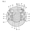
- Fig. 2 is a schematic sectional view of the connecting structure taken along a plane including a center axis of the lock pin 3 and a direction perpendicular to an axial direction of the rolling roll 1.
- this connecting structure includes a spring member 4, a washer 5, and a nut 6.
- the lock pin 3 has a head part 31, a shaft 32 which is connected to the head part 31, and an engaging projection 33.
- the shaft 32 has the cutout part 35 and a screw part 36.
- the screw part 36 is positioned in a tip end part of the shaft 32 at an opposite side to the head part 31.
- the cutout part 35 is positioned between the head part 31 and the screw part 36.
- the cutout part 35 has a laterally symmetrical dish-like shape in section, as shown in Fig. 2 .
- the spring member 4 is so arranged as to surround the shaft 32.
- An end part of the lock pin inserting hole 39 in the coupling 2 at a side where the shaft 32 is engaged has a step part 24 which is extended outward in a radial direction.
- An inner diameter of an inner peripheral face of the lock pin inserting hole 39 which is positioned outward than the step part 24 in the axial direction is formed larger than that of the inner peripheral face which is positioned inward than the step part 24 in the axial direction.
- the washer 5 is so arranged as to surround the shaft 32, and butted against the other end part of the spring member 4. Moreover, the nut 6 is screwed on the screw part 36 of the shaft 32 thereby to tighten the washer 5 toward the head part 31.
- reference numeral 25 represents a liner
- reference numerals 26 to 29 represent screws, although not specifically described.
- the liner 25 is secured with the screws 26 to 29.
- the rolling roll 1 and the roll neck engaging hole 41 are made concentric.
- the schematic sectional view in Fig. 1 corresponds to a sectional plane taken along a line A-A in Fig. 2 , which is, a line vertically bisecting the cutout part 35 having the laterally symmetrical dish-like shape.
- Fig. 3 is a perspective view of the lock pin 3.
- the lock pin 3 has a step part 85 between the cutout part 35 and the screw part 36. Referring to Fig. 2 , the washer 5 is pressed with the nut 6 against this step part 85. Moreover, the lock pin 3 is provided with a pin inserting hole 80 near the head part 31, as shown in Fig. 3 . Function of this pin inserting hole 80 will be fully described below.
- the above described connecting structure can be formed, for example, in the following manner. Specifically, in a state where the cutout part 35 of the lock pin 3 is directed to the roll neck engaging hole 41, the lock pin 3 is inserted into the lock pin inserting hole 39. Thereafter, the roll neck part 43 of the rolling roll 1 is inserted into the roll neck engaging hole 41. Finally, by rotating the lock pin 3 in a manner fully described below, a peripheral part 47 (See Figs. 2 and 3 ) of the lock pin 3 is engaged with an engaging groove 48 (See Fig. 2 ) in the roll neck part 43. As the results, movement of the roll neck part 43 in the axial direction is restricted, and thus, the connecting structure is formed.
- Fig. 4 is a perspective view showing the end part of the lock pin 3 at the side of the head part 31, which shows a region around the engaging projection 33 of the lock pin 3.
- the engaging projection 33 includes a rotation direction engaging part 50 and an engaging flange part 51.
- the rotation direction engaging part 50 is connected to the head part 31, and the engaging flange part 51 is connected to the rotation direction engaging part 50.
- the engaging flange part 51 has an end face in the axial direction having a shape of a running track, and is formed in a substantially oblong shape.
- the engaging flange part 51 has a first side face 60 and a second side face 61 which are substantially parallel to each other.
- the first and second side faces 60, 61 are substantially the same, and have a rectangular shape.
- the first side face 60 is substantially completely overlapped on the second side face 61 in a normal direction of the first side face 60.
- a distance between the first side face 60 and the second side face 61 (a width between two faces) is set to be d[cm].
- the side face of the engaging flange part 51 includes the first and second side faces 60, 61, a first curved face 62, and a second curved face 63.
- the first curved face 62 exists between one end of the first side face 60 and one end of the second side face 61
- the second curved face 63 exists between the other end of the first side face 60 and the other end of the second side face 61.
- the rotation direction engaging part 50 is positioned in a region where the engaging flange part 51 passes, when the engaging flange part 51 moves toward the shaft 32 in the axial direction.
- Fig. 5 is a sectional view of the rotation direction engaging part 50 taken along a plane perpendicular to the axial direction.
- the rotation direction engaging part 50 has a sectional shape of parallelogram in which four edges have substantially the same length.
- the rotation direction engaging part 50 has such a shape that a prism having a sectional shape of parallelogram in which four edges have substantially the same length is tapered at its respective four corners.
- the rotation direction engaging part 50 has a substantially lemon-like shape in section.
- the rotation direction engaging part 50 has a first side face 71 and a second side face 72 which are positioned substantially in parallel with each other and separated by a distance d[cm] which is substantially equal to the distance d[cm] between the first side face 60 and the second side face 61 of the engaging flange part 51. Moreover, the rotation direction engaging part 50 has a third side face 73 and a fourth side face 74 which are positioned substantially in parallel with each other and separated by a distance d[cm] which is substantially equal to the distance d[cm] between the first side face 60 and the second side face 61 of the engaging flange part 51.
- a sectional plane of the rotation direction engaging part 50 taken along a plane perpendicular to the axial direction is smaller than a sectional plane of the engaging flange part 51 taken along a plane perpendicular to the axial direction.
- a position in a rotation direction (phase) of a corner part 76 out of four corner parts of the rotation direction engaging part 50 substantially coincides with a position in the rotation direction (phase) of a center of the first side face 60 of the engaging flange part 51.
- a position in the rotation direction (phase) of the other corner part 77 out of the four corner parts of the rotation direction engaging part 50 substantially coincides with a position in the rotation direction (phase) of a center of the second side face 61 of the engaging flange part 51.
- Fig. 6 is a perspective view of the end part of the lock pin 3 at the side of the head part 31, as seen from a different direction from in Fig. 4 .
- the end part of the lock pin 3 at the side of the head part 31 has the pin inserting hole 80 which is provided across the head part 31 and the shaft 32.
- a rotation restricting pin (not shown) of the lock pin 3 is adapted to be inserted into this pin inserting hole 80.
- Fig. 7 is a schematic view for explaining a rotation restricting structure for restricting the rotation of the lock pin 3 with respect to the coupling 2.
- reference numeral 88 represents the pin which is inserted into the pin inserting hole 80 which is shown in Fig. 6 .
- the coupling 2 has a cutout 90 in a substantially semicircular shape which substantially corresponds to a curvature of a head part of the pin 88.
- the lock pin 3 by moving the lock pin 3 with respect to the coupling 2 in the axial direction of the lock pin 3, that is, the direction of an arrow mark A in Fig. 7 , the head part of the pin 88 which has been inserted into and engaged with the cutout 90 can be detached from the cutout 90 thereby to release the rotation restriction of the lock pin 3.
- the lock pin 3 can prevent the roll neck part 43 from rotating between an axial direction restricting position where the movement of the roll neck part 43 in the axial direction with respect to the coupling 2 is restricted and a shaft insertion allowing position where the roll neck part 43 can be inserted into the coupling 2.
- Fig. 8 is a view showing a lock pin rotating tool which is used for rotating the lock pin 3.
- This lock pin rotating tool (hereinafter referred to simply as "the tool") has a body part including, for example, a columnar part 99, a shaft part 91, and a torque applying part 92.
- the shaft part 91 is connected to one end of the columnar part 99
- the torque applying part 92 is connected to an end of the shaft part 91 at an opposite side to the columnar part 99.
- the columnar part 99 and the shaft part 91 are substantially aligned in the axial direction.
- the torque applying part 92 is extended in a direction perpendicular to an extending direction of the shaft part 91. By rotating the torque applying part 92, it is possible to rotate the columnar part 99.
- the columnar part 99 is provided with a hole which opens to an end face thereof at an opposite side to the shaft part 91 in the axial direction. Specifically, the columnar part 99 has a first hole 94 and a second hole 95. The first hole 94 opens to the end face of the columnar part 99 in the axial direction.
- the first hole 94 has a sectional plane substantially corresponding to the end face in the axial direction of the engaging flange part which is represented by reference numeral 51 in Fig. 5 (the sectional plane which is slightly larger than the end face in the axial direction of the engaging flange part 51), so that the engaging flange part 51 can pass through the first hole 94.
- the second hole 95 is continued from the first hole 94 via a step part.
- An inner peripheral face of the second hole 95 is continued from an inner peripheral face of the first hole 94 via the step part which is extended outward in a radial direction from the inner peripheral face of the first hole 94.
- the second hole 95 has a larger sectional plane than the sectional plane of the first hole 94.
- An axial length h2 [cm] of the first hole 94 is smaller than an axial length h1 [cm] of the rotation direction engaging part which is represented by reference numeral 50 in Fig. 4 .
- the inner peripheral face of the first hole 94 is adapted to be engaged with the side face of the rotation direction engaging part 50 in a rotation direction.
- the first hole 94 has the sectional plane which is substantially equal to the end face in the axial direction of the engaging flange part 51, and two side faces having a width d[cm] between the two faces corresponding to the first and second side faces of the engaging flange part 51.
- the rotation direction engaging part 50 also has the first side face 71 and the second side face 72 having the width d[cm] between them, and the third side face 73 and the third side face 74 having the width d[cm] between them.
- the two side faces of the first hole 94 having the width d[cm] between them are so arranged as to clamp the first side face 71 and the second side face 72 of the rotation direction engaging part 50, or so arranged as to clamp the third side face 73 and the fourth side face 74 of the rotation direction engaging part 50, the tool can be engaged with the rotation direction engaging part 50 so as not to relatively move in the rotation direction with respect to each other.
- the rotation direction engaging part 50 is positioned within the region where the engaging flange part 51 passes. Moreover, the sectional plane of the rotation direction engaging part 50 taken along the plane perpendicular to the axial direction is smaller than the sectional plane of the engaging flange part 51 taken along the plane perpendicular to the axial direction.
- the lock pin 3 which can be rotated by only one operator, thus enabling the number of the working steps to be reduced, can be constructed in a simple structure. Moreover, according to the above described embodiment, it is possible to realize a connection releasing structure including the lock pin 3 and the tool, and enabling the lock pin 3 to be rotated by only one operator.
- the engaging flange part 51 has the substantially oblong shape, while the rotation direction engaging part 50 has the sectional shape of parallelogram in which the four edges have the substantially equal length. Therefore, a region of the tool to be frictionally engaged with the end face of the engaging flange part 51 at the side of the rotation direction engaging part 50 can be made larger, and hence, the engagement in the axial direction can be more reliably performed.
- the engaging projection 33 has only to be connected to the head part 31 of the lock pin 3. Therefore, it is possible to prevent the lock pin 3 from jumping out from the outer peripheral face of the coupling 2 outward in the radial direction. As the results, a swing diameter of the rotation will not be increased.
- the rotation restriction of the lock pin 3 is performed, by engaging the head part of the pin 88 which is fixed to the lock pin 3 with the cutout 90 in the coupling 2.
- the rotation restriction of the lock pin 3 is performed by engaging the convex part of the lock pin 3 with the concave part of the coupling 2.
- it is also possible to perform the rotation restriction by forming a concave part in the lock pin, and a convex part in the coupling, and then, by engaging the concave part in the lock pin with the convex part in the coupling.
- the rotation restricting mechanism may be in any structure, provided that relative rotation of the lock pin with respect to the lock pin inserting member can be prevented.
- the rotation restricting mechanism of the coupling need not be necessarily provided. Even though the rotation restricting mechanism is not provided, it is possible to make the lock pin so as not to be rotated by frictional force. In this case, by detaching the lock pin from the coupling, it is possible to cancel the frictional force.
- the body part of the tool has a columnar shape.
- the body part of the tool may have any other shape such as a prism shape.
- the engaging flange part 51 has a shape of a running track in section
- the rotation direction engaging part 50 has a substantially lemon-like shape in section (a shape of substantially parallelogram in section).
- Fig. 9 that is, a schematic view of an engaging projection 133 of a lock pin 103 in a modified example, as seen from outside in the axial direction
- centers of the two sectional shapes may be made aligned, and further, a width d [cm] of the substantially rectangular sectional shape may be made substantially equal to a width d[cm] between two longer faces of the hexagonal sectional shape.
- the engaging projection may have any shape, provided that the engaging flange part has a first side face and a second side face which are substantially parallel to each other, and the rotation direction engaging part is positioned within a region where the engaging flange part passes, when the engaging flange part is moved in the axial direction toward the shaft, and at the same time, has a first side face and a second side face which are substantially parallel to each other, and separated from each other by a distance substantially equal to a distance between the first and second side faces of the engaging flange part, and that a sectional plane of the rotation direction engaging part taken along a plane perpendicular to the axial direction is smaller than a sectional plane of the engaging flange part taken along a plane perpendicular to the axial direction.
- the engaging flange part and the rotation direction engaging part need not necessarily have the side faces which are substantially parallel to each other. It would be sufficient that the engaging projection has a rotation direction engaging part which is connected to the head part and can be engaged in a rotation direction, and an engaging flange part which is connected to the rotation direction engaging part and can be engaged in an axial direction. Moreover, positions in the rotation direction engaging part to be engaged with the hole in the tool may be at two side faces which are opposed to each other in a substantially V-shape.
- the tool according to the invention is not limited to the above described embodiment. It would be sufficient that the tool has a first hole which has a sectional plane substantially corresponding to the end face in the axial direction of the engaging flange part, and the engaging flange part can pass through, and a second hole which has an inner peripheral face continued from an inner peripheral face of the first hole, via a step part extending outward in a radial direction from the inner peripheral face of the first hole, the second hole having a sectional plane which is larger than the sectional plane of the first hole, and a length of the first hole is smaller than a thickness in the axial direction of the rotation direction engaging part.
- connection releasing structure includes the lock pin and the lock pin rotating tool for rotating the lock pin, wherein the tool includes a first hole which has a sectional plane substantially corresponding to the end face in the axial direction of the engaging flange part of the lock pin, and the engaging flange part can pass through, and a second hole which has an inner peripheral face continued from an inner peripheral face of the first hole, via a step part extending outward in a radial direction from the inner peripheral face of the first hole, the second hole having a sectional plane which is larger than the sectional plane of the first hole, a length of the first hole is smaller than a thickness in the axial direction of the rotation direction engaging part, an inner face of the first hole can be engaged with a side face of the rotation direction engaging part in the rotation direction, and at least a part of the step part can be engaged with, in the axial direction, at least a part of the end face of the engaging flange part at a side of the rotation direction engaging part in the
- lock pin according to the invention can be used for other purposes than the connecting mechanism for connecting the rolling roll of the rolling mill to the coupling which is connected to the drive shaft.
- the lock pin which can be rotated by only one operator thereby enabling the number of working steps to be reduced, the lock pin rotating tool, and the connection releasing structure.
Landscapes
- Engineering & Computer Science (AREA)
- General Engineering & Computer Science (AREA)
- Mechanical Engineering (AREA)
- Snaps, Bayonet Connections, Set Pins, And Snap Rings (AREA)
Abstract
Description
- The present invention relates to a lock pin, a lock pin rotating tool, and a connection releasing structure. More particularly, the invention relates to the lock pin which can be favorably used in a connecting structure for connecting, for example, a rolling roll of a rolling mill to a coupling which is connected to a drive shaft, the lock pin rotating tool, and the connection releasing structure.
- Conventionally, as an example of the lock pin, there has been a lock pin which is used in a connecting structure disclosed in
JP-A-H02-229607 - This lock pin is inserted into a lock pin inserting hole in the coupling, in a state where the cutout is directed to a roll neck engaging hole in the coupling. Then, in this state, a roll neck part is inserted into the roll neck engaging hole in the coupling. Thereafter, by rotating the lock pin, a peripheral part of the lock pin is engaged with an engaging groove of the roll neck part, thereby to restrict movement of the roll neck part in the axial direction.
- Moreover, for the purpose of reliably preventing the movement of the roll neck part in the axial direction, rotation restriction of the lock pin is performed, in a state where the peripheral part of the lock pin is engaged with the engaging groove of the roll neck part. This rotation restriction is performed by forming a projection on a head part of a bolt of the lock pin, and by engaging this projection with a recess which is formed in the coupling corresponding to the projection. The rotation restriction will not be released, because the projection is always urged toward the recess by an urging member. Moreover, a nut is screwed on a tip end of the lock pin.
- By the way, in the above described conventional lock pin, when the engagement of the lock pin is to be released, an operator at a side of the nut on the tip end of the lock pin presses a shaft of the lock pin toward the head part of the lock pin so as to overcome an urging force of the urging member thereby to detach the projection from the recess. In this state, another operator at a side of the head part of the lock pin rotates the lock pin with a wrench or the like thereby to release the engagement of the lock pin.
- However, in the above described conventional lock pin, there is such a problem that it requires a number of working steps, because the two operators are required for rotating the lock pin, at opposite ends, namely, at the side of the nut on the tip end of the lock pin, and at the side of the head part.
- Patent Document 1:
JP-A-H02-229607 - In view of the above, an object of the invention is to provide a lock pin, a lock pin rotating tool, and a connection releasing structure for allowing only one operator to release engagement thereby to reduce the number of working steps.
- In order to solve the above described problem, there is provided according to the invention, a lock pin comprising: a head part; a shaft which is continued from the head part, and which has a cutout part and a screw part which is positioned at a tip end side forward of the cutout part; and an engaging projection which is continued from the head part at an opposite side to the screw part, characterized in that the engaging projection has: a rotation direction engaging part which is connected to the head part, and which can be engaged in a rotation direction; and an engaging flange part which is connected to the rotation direction engaging part, and which can be engaged in an axial direction.
- According to the invention, the engaging projection which is continued from the head part has the rotation direction engaging part which can be engaged in the rotation direction, and the engaging flange part which can be engaged in the axial direction. Therefore, it is possible to prepare a tool having a rotation force applying part which can be engaged with the rotation direction engaging part in the rotation direction, and an axial force applying part which can be engaged with the engaging flange part in the axial direction. Then, it is possible to engage the axial force applying part with the engaging flange in the axial direction, and at the same time, to engage the rotation force applying part with the rotation direction engaging part. Therefore, after a force is applied from the tool to the lock pin in the axial direction so that a frictional force may not work between the head part and the lock pin inserting member, a rotation force (torque) can be applied from the tool to the lock pin thereby to rotate the lock pin. As the results, it is possible to rotate the lock pin by only one operator, and hence, the number of working steps for engagement using the lock pin can be reduced.
- Moreover, in one embodiment, the engaging flange part has a first side face and a second side face which are substantially parallel to each other. The rotation direction engaging part is positioned within a region where the engaging flange part passes, when the engaging flange part is moved in the axial direction toward the shaft, and has a first side face and a second side face which are substantially parallel to each other, and separated from each other by a distance substantially equal to a distance between the first and second side faces of the engaging flange part. Moreover, a sectional plane of the rotation direction engaging part taken along a plane perpendicular to the axial direction is smaller than a sectional plane of the engaging flange part taken along a plane perpendicular to the axial direction.
- According to the above described embodiment, as the tool for rotating the lock pin, it is possible to employ a tool having a first hole which has a sectional plane substantially corresponding to the end face in the axial direction of the engaging flange part, and the engaging flange part can pass through, and a second hole which has an inner peripheral face continued from an inner peripheral face of the first hole, via a step part extending outward in a radial direction from the inner peripheral face of the first hole. The second hole has a sectional plane which is larger than the sectional plane of the first hole, and a length of the first hole is smaller than a thickness in the axial direction of the rotation direction engaging part.
- Specifically, by arranging two side faces of the first hole corresponding to the first side face and the second side face of the engaging flange part so as to clamp the first side face and the second side face, the tool can be engaged with the rotation direction engaging part so as not to relatively move in the rotation direction with respect to each other. Moreover, by pulling the tool in this state, it is possible to frictionally engage, in the axial direction, at least a part of the step part with at least a part of the end face of the engaging flange part at a side of the rotation direction engaging part in the axial direction, and further, to make the head part of the lock pin so as not to be contacted with the lock pin inserting member. In this manner, the lock pin can be smoothly rotated. According to this embodiment, it is possible to form the lock pin which can be rotated by only one operator, thus reducing the number of working steps, in a simple structure.
- Moreover, in another embodiment, the engaging flange part has a substantially oblong shape, while the rotation direction engaging part has a sectional shape of parallelogram in which four edges have substantially equal length. A position of one of four corners of the rotation direction engaging part in the rotation direction substantially coincides with a position of a center of the first side face of the engaging flange part in the rotation direction, and a position of another one of the four corners of the rotation direction engaging part in the rotation direction substantially coincides with a position of a center of the second side face of the engaging flange part in the rotation direction.
- According to the above described embodiment, it is possible to enlarge a region where the step part of the tool is frictionally engaged with the end face of the engaging flange part at the side of the rotation direction engaging part in the axial direction. In this manner, the engagement in the axial direction can be reliably performed.
- Further, the lock pin rotating tool for rotating the lock pin according to the invention is characterized by comprising: a body part; and a torque applying part for rotating the body part in the rotation direction, wherein the body part has: a first hole which has a sectional plane substantially corresponding to an end face in the axial direction of the engaging flange part, and through which the engaging flange part can pass; and a second hole which has an inner peripheral face continued from an inner peripheral face of the first hole, via a step part extending outward in a radial direction from the inner peripheral face of the first hole, the second hole having a sectional plane which is larger than the sectional plane of the first hole, and a length of the first hole is smaller than a thickness in the axial direction of the rotation direction engaging part.
- According to this invention, by arranging the lock pin rotating tool in such a manner that the side face of the engaging flange part and the side face of the first hole corresponding to the side face of the engaging flange part are opposed to each other, it is possible to engage the tool with the rotation direction engaging part so as not to relatively move with respect to each other. Then, by pulling the tool in this state, it is possible to frictionally engage, in the axial direction, at least a part of the step part with at least a part of the end face of the engaging flange part at the side of the rotation direction engaging part in the axial direction, and at the same time, it is possible to pull up the lock pin. Accordingly, it is possible to make the head part of the lock pin so as not to be contacted with the lock pin inserting member, and to smoothly rotate the lock pin. In the one embodiment, rotation restriction of the lock pin can be released. Therefore, it is possible to rotate the lock pin by only one operator, and hence, the number of working steps can be reduced.
- Further, a connection releasing structure according to the invention comprises: the lock pin according to the invention; and the lock pin rotating tool for rotating the lock pin. The lock pin rotating tool includes: a body part; and a torque applying part for rotating the body part in the rotation direction, the body part has: a first hole which has a sectional plane substantially corresponding to an end face in the axial direction of the engaging flange part, and through which the engaging flange part can pass; and a second hole which has an inner peripheral face continued from an inner peripheral face of the first hole, via a step part extending outward in a radial direction from the inner peripheral face of the first hole, the second hole having a sectional plane which is larger than the sectional plane of the first hole, a length of the first hole is smaller than a thickness in the axial direction of the rotation direction engaging part, an inner face of the first hole can be engaged with a side face of the rotation direction engaging part in the rotation direction, and at least a part of the step part can be engaged with, in the axial direction, at least a part of an end face of the engaging flange part at a side of the rotation direction engaging part in the axial direction.
- According to the invention, it is possible to realize the connection releasing structure in which the lock pin can be rotated by only one operator.
- According to the invention, it is possible to realize a lock pin, a lock pin rotating tool, and a connection releasing structure in which the lock pin can be rotated by only one operator, and hence, the number of working steps can be reduced.
-
- [
FIG. 1] Fig. 1 is a schematic sectional view showing a connecting structure for connecting a rolling roll with a coupling in an embodiment according to the invention. - [
FIG. 2] Fig. 2 is a schematic sectional view of the connecting structure taken along a plane including a center axis of a lock pin and a direction perpendicular to an axial direction of the rolling roll. - [
FIG. 3] Fig. 3 is a perspective view of the lock pin. - [
FIG. 4] Fig. 4 is a perspective view showing an end part of the lock pin at a side of a head part thereof, showing a region around an engaging projection of the lock pin. - [
FIG. 5] Fig. 5 is a sectional view of a rotation direction engaging part taken along a plane perpendicular to an axial direction. - [
FIG. 6] Fig. 6 is a perspective view of the end part of the lock pin at the side of the head part, as seen from a different direction from inFig. 4 . - [
FIG. 7] Fig. 7 is a schematic view for explaining a rotation restricting structure of the lock pin for restricting the rotation of the lock pin with respect to the coupling. - [
FIG. 8] Fig. 8 is a view showing a lock pin rotating tool which is used for rotating the lock pin. - [
FIG. 9] Fig. 9 is a schematic view of an engaging projection of the lock pin in a modified example, as seen from outside in the axial direction. - Now, the invention will be described in detail, referring to embodiments as shown in the drawings.
-
Fig. 1 is a schematic sectional view showing a connecting structure for connecting arolling roll 1 with acoupling 2 in an embodiment according to the invention. - This connecting structure includes the rolling
roll 1, thecoupling 2, and alock pin 3. The rollingroll 1 has aroll neck part 43, while thecoupling 2 has a rollneck engaging hole 41. Theroll neck part 43 is engaged with the rollneck engaging hole 41. As shown inFig. 1 , the rollingroll 1 has agroove 21 which is formed on an outerperipheral face 20 of theroll neck part 43 and extended in a direction perpendicular to an axial direction of the rollingroll 1. Thecoupling 2 has agroove 23 which is formed on an innerperipheral face 22 of the rollneck engaging hole 41 and extended in a direction perpendicular to the axial direction. - As shown in
Fig. 1 , thegroove 21 in the rollingroll 1 and thegroove 23 in thecoupling 2 respectively have a substantially semicircular shape in section, and they are mated with each other thereby to form a lockpin inserting hole 39 in a substantially circular shape. In the sectional view inFig. 1 , the lockpin inserting hole 39 is extended in a tangential direction of the outerperipheral face 20 of theroll neck part 43. Thelock pin 3 is inserted into the lockpin inserting hole 39. Thelock pin 3 has a function of preventing relative movement of the rollingroll 1 with respect to thecoupling 2 in the axial direction of the rollingroll 1. Moreover, thelock pin 3 has acutout part 35. The function of thelock pin 3 and structure of thecutout part 35 will be fully described below. -
Fig. 2 is a schematic sectional view of the connecting structure taken along a plane including a center axis of thelock pin 3 and a direction perpendicular to an axial direction of the rollingroll 1. - As shown in
Fig. 2 , in addition to the rollingroll 1, thecoupling 2 and thelock pin 3, this connecting structure includes aspring member 4, a washer 5, and a nut 6. Thelock pin 3 has ahead part 31, ashaft 32 which is connected to thehead part 31, and an engagingprojection 33. Theshaft 32 has thecutout part 35 and ascrew part 36. Thescrew part 36 is positioned in a tip end part of theshaft 32 at an opposite side to thehead part 31. Thecutout part 35 is positioned between thehead part 31 and thescrew part 36. Thecutout part 35 has a laterally symmetrical dish-like shape in section, as shown inFig. 2 . - The
spring member 4 is so arranged as to surround theshaft 32. An end part of the lockpin inserting hole 39 in thecoupling 2 at a side where theshaft 32 is engaged has astep part 24 which is extended outward in a radial direction. An inner diameter of an inner peripheral face of the lockpin inserting hole 39 which is positioned outward than thestep part 24 in the axial direction is formed larger than that of the inner peripheral face which is positioned inward than thestep part 24 in the axial direction. In this manner, a part of thespring member 4 surrounding theshaft 32 can be contained inside the inner peripheral face having the larger diameter, thereby enabling one end part of thespring member 4 to obtain a repulsive force from thestep part 24. - As shown in
Fig. 2 , the washer 5 is so arranged as to surround theshaft 32, and butted against the other end part of thespring member 4. Moreover, the nut 6 is screwed on thescrew part 36 of theshaft 32 thereby to tighten the washer 5 toward thehead part 31. InFig. 2 ,reference numeral 25 represents a liner, andreference numerals 26 to 29 represent screws, although not specifically described. Theliner 25 is secured with thescrews 26 to 29. By clamping flat faces 83, 84 of theroll neck part 43 which are substantially parallel to each other by means of theliner 25, the rollingroll 1 and the rollneck engaging hole 41 are made concentric. It is to be noted that the schematic sectional view inFig. 1 corresponds to a sectional plane taken along a line A-A inFig. 2 , which is, a line vertically bisecting thecutout part 35 having the laterally symmetrical dish-like shape. -
Fig. 3 is a perspective view of thelock pin 3. - As shown in
Fig. 3 , thelock pin 3 has astep part 85 between thecutout part 35 and thescrew part 36. Referring toFig. 2 , the washer 5 is pressed with the nut 6 against thisstep part 85. Moreover, thelock pin 3 is provided with apin inserting hole 80 near thehead part 31, as shown inFig. 3 . Function of thispin inserting hole 80 will be fully described below. - The above described connecting structure can be formed, for example, in the following manner. Specifically, in a state where the
cutout part 35 of thelock pin 3 is directed to the rollneck engaging hole 41, thelock pin 3 is inserted into the lockpin inserting hole 39. Thereafter, theroll neck part 43 of the rollingroll 1 is inserted into the rollneck engaging hole 41. Finally, by rotating thelock pin 3 in a manner fully described below, a peripheral part 47 (SeeFigs. 2 and3 ) of thelock pin 3 is engaged with an engaging groove 48 (SeeFig. 2 ) in theroll neck part 43. As the results, movement of theroll neck part 43 in the axial direction is restricted, and thus, the connecting structure is formed. -
Fig. 4 is a perspective view showing the end part of thelock pin 3 at the side of thehead part 31, which shows a region around the engagingprojection 33 of thelock pin 3. - The engaging
projection 33 includes a rotationdirection engaging part 50 and an engagingflange part 51. The rotationdirection engaging part 50 is connected to thehead part 31, and the engagingflange part 51 is connected to the rotationdirection engaging part 50. - As shown in
Fig. 4 , the engagingflange part 51 has an end face in the axial direction having a shape of a running track, and is formed in a substantially oblong shape. The engagingflange part 51 has afirst side face 60 and asecond side face 61 which are substantially parallel to each other. The first and second side faces 60, 61 are substantially the same, and have a rectangular shape. Thefirst side face 60 is substantially completely overlapped on thesecond side face 61 in a normal direction of thefirst side face 60. A distance between thefirst side face 60 and the second side face 61 (a width between two faces) is set to be d[cm]. - The side face of the engaging
flange part 51 includes the first and second side faces 60, 61, a firstcurved face 62, and a secondcurved face 63. The firstcurved face 62 exists between one end of thefirst side face 60 and one end of thesecond side face 61, and the secondcurved face 63 exists between the other end of thefirst side face 60 and the other end of thesecond side face 61. - The rotation
direction engaging part 50 is positioned in a region where the engagingflange part 51 passes, when the engagingflange part 51 moves toward theshaft 32 in the axial direction.Fig. 5 is a sectional view of the rotationdirection engaging part 50 taken along a plane perpendicular to the axial direction. As shown inFig. 5 , the rotationdirection engaging part 50 has a sectional shape of parallelogram in which four edges have substantially the same length. Accurately, the rotationdirection engaging part 50 has such a shape that a prism having a sectional shape of parallelogram in which four edges have substantially the same length is tapered at its respective four corners. In short, the rotationdirection engaging part 50 has a substantially lemon-like shape in section. - The rotation
direction engaging part 50 has afirst side face 71 and asecond side face 72 which are positioned substantially in parallel with each other and separated by a distance d[cm] which is substantially equal to the distance d[cm] between thefirst side face 60 and thesecond side face 61 of the engagingflange part 51. Moreover, the rotationdirection engaging part 50 has athird side face 73 and a fourth side face 74 which are positioned substantially in parallel with each other and separated by a distance d[cm] which is substantially equal to the distance d[cm] between thefirst side face 60 and thesecond side face 61 of the engagingflange part 51. - As shown in
Fig. 4 , a sectional plane of the rotationdirection engaging part 50 taken along a plane perpendicular to the axial direction is smaller than a sectional plane of the engagingflange part 51 taken along a plane perpendicular to the axial direction. Moreover, referring toFigs. 4 and 5 , a position in a rotation direction (phase) of acorner part 76 out of four corner parts of the rotationdirection engaging part 50 substantially coincides with a position in the rotation direction (phase) of a center of thefirst side face 60 of the engagingflange part 51. Further, a position in the rotation direction (phase) of theother corner part 77 out of the four corner parts of the rotationdirection engaging part 50 substantially coincides with a position in the rotation direction (phase) of a center of thesecond side face 61 of the engagingflange part 51. -
Fig. 6 is a perspective view of the end part of thelock pin 3 at the side of thehead part 31, as seen from a different direction from inFig. 4 . - As shown in
Fig. 6 , the end part of thelock pin 3 at the side of thehead part 31 has thepin inserting hole 80 which is provided across thehead part 31 and theshaft 32. A rotation restricting pin (not shown) of thelock pin 3 is adapted to be inserted into thispin inserting hole 80. -
Fig. 7 is a schematic view for explaining a rotation restricting structure for restricting the rotation of thelock pin 3 with respect to thecoupling 2. InFig. 7 ,reference numeral 88 represents the pin which is inserted into thepin inserting hole 80 which is shown inFig. 6 . - As shown in
Fig. 7 , thecoupling 2 has acutout 90 in a substantially semicircular shape which substantially corresponds to a curvature of a head part of thepin 88. In this embodiment, by moving thelock pin 3 with respect to thecoupling 2 in the axial direction of thelock pin 3, that is, the direction of an arrow mark A inFig. 7 , the head part of thepin 88 which has been inserted into and engaged with thecutout 90 can be detached from thecutout 90 thereby to release the rotation restriction of thelock pin 3. - On the other hand, referring to
Fig. 2 , in case where a force is not applied to thelock pin 3, the head part of thepin 88 is engaged with thecutout 90 due to a force which is applied to the washer 5 by thespring 4 in the axial direction, that is, a direction of an arrow mark B inFig. 7 , thereby to prevent thelock pin 3 from rotating with respect to thecoupling 2. In this manner, in the connecting structure, the movement of theroll neck part 43 in the axial direction is restricted. - There are formed the two
cutouts 90 near the lockpin inserting hole 39 in thecoupling 2, at two positions having a phase difference of 180 degree. Accordingly, thelock pin 3 can prevent theroll neck part 43 from rotating between an axial direction restricting position where the movement of theroll neck part 43 in the axial direction with respect to thecoupling 2 is restricted and a shaft insertion allowing position where theroll neck part 43 can be inserted into thecoupling 2. -
Fig. 8 is a view showing a lock pin rotating tool which is used for rotating thelock pin 3. - This lock pin rotating tool (hereinafter referred to simply as "the tool") has a body part including, for example, a
columnar part 99, ashaft part 91, and atorque applying part 92. Theshaft part 91 is connected to one end of thecolumnar part 99, and thetorque applying part 92 is connected to an end of theshaft part 91 at an opposite side to thecolumnar part 99. Thecolumnar part 99 and theshaft part 91 are substantially aligned in the axial direction. Moreover, thetorque applying part 92 is extended in a direction perpendicular to an extending direction of theshaft part 91. By rotating thetorque applying part 92, it is possible to rotate thecolumnar part 99. - The
columnar part 99 is provided with a hole which opens to an end face thereof at an opposite side to theshaft part 91 in the axial direction. Specifically, thecolumnar part 99 has afirst hole 94 and asecond hole 95. Thefirst hole 94 opens to the end face of thecolumnar part 99 in the axial direction. - The
first hole 94 has a sectional plane substantially corresponding to the end face in the axial direction of the engaging flange part which is represented byreference numeral 51 inFig. 5 (the sectional plane which is slightly larger than the end face in the axial direction of the engaging flange part 51), so that the engagingflange part 51 can pass through thefirst hole 94. Thesecond hole 95 is continued from thefirst hole 94 via a step part. An inner peripheral face of thesecond hole 95 is continued from an inner peripheral face of thefirst hole 94 via the step part which is extended outward in a radial direction from the inner peripheral face of thefirst hole 94. Thesecond hole 95 has a larger sectional plane than the sectional plane of thefirst hole 94. - An axial length h2 [cm] of the
first hole 94 is smaller than an axial length h1 [cm] of the rotation direction engaging part which is represented byreference numeral 50 inFig. 4 . The inner peripheral face of thefirst hole 94 is adapted to be engaged with the side face of the rotationdirection engaging part 50 in a rotation direction. Specifically, thefirst hole 94 has the sectional plane which is substantially equal to the end face in the axial direction of the engagingflange part 51, and two side faces having a width d[cm] between the two faces corresponding to the first and second side faces of the engagingflange part 51. On the other hand, the rotationdirection engaging part 50 also has thefirst side face 71 and thesecond side face 72 having the width d[cm] between them, and thethird side face 73 and the third side face 74 having the width d[cm] between them. When the two side faces of thefirst hole 94 having the width d[cm] between them are so arranged as to clamp thefirst side face 71 and thesecond side face 72 of the rotationdirection engaging part 50, or so arranged as to clamp thethird side face 73 and the fourth side face 74 of the rotationdirection engaging part 50, the tool can be engaged with the rotationdirection engaging part 50 so as not to relatively move in the rotation direction with respect to each other. - As described above, when the engaging
flange part 51 is moved toward theshaft 32 in the axial direction, the rotationdirection engaging part 50 is positioned within the region where the engagingflange part 51 passes. Moreover, the sectional plane of the rotationdirection engaging part 50 taken along the plane perpendicular to the axial direction is smaller than the sectional plane of the engagingflange part 51 taken along the plane perpendicular to the axial direction. Therefore, when a user pulls the tool in a state where the tool is engaged with the rotationdirection engaging part 50 so as not to relatively move in the rotation direction with respect to each other, it is possible to frictionally engage, in the axial direction, a part of the step part between thefirst hole 94 and thesecond hole 95 with at least a part of the end face of the engagingflange part 51 at a side of the rotationdirection engaging part 50 in the axial direction. In this manner, it is possible to engage the tool with the engagingflange part 51 in the axial direction. - Accordingly, when the user further pulls the tool, in a state where a part of the step part is engaged with, in the axial direction, at least a part of the end face of the engaging
flange part 51 at the side of the rotationdirection engaging part 50 in the axial direction, it is possible to release the rotation restriction of thelock pin 3, as described referring toFig. 7 . In this state, when the user rotates the torque applying part 92 (SeeFig. 8 ), it is possible to rotate thelock pin 3. - According to the above described embodiment, after the rotation restriction is released by applying a force from the tool to the
lock pin 3 in the axial direction, it is possible to rotate thelock pin 3, by applying a torque from the tool to thelock pin 3. Therefore, it is possible to rotate thelock pin 3 by only one operator, and hence, the number of working steps in engagement using thelock pin 3 can be reduced. - Moreover, according to the above described embodiment, when the two side faces of the
first hole 94 corresponding to thefirst side face 60 and thesecond side face 61 of the engagingflange part 51 are so arranged as to clamp thefirst side face 71 and thesecond side face 72 of the rotationdirection engaging part 50, or so arranged as to clamp thethird side face 73 and the fourth side face 74 of the rotationdirection engaging part 50, it is possible to engage the tool with the rotationdirection engaging part 50 so as not to relatively move in the rotation direction with respect to each other. Then, by pulling the tool in this state, it is possible to frictionally engage, in the axial direction, a part of the step part with at least a part of the end face of the engagingflange part 51 at the side of the rotationdirection engaging part 50 in the axial direction, thereby to release the rotation restriction of thelock pin 3. According to the above described embodiment, thelock pin 3 which can be rotated by only one operator, thus enabling the number of the working steps to be reduced, can be constructed in a simple structure. Moreover, according to the above described embodiment, it is possible to realize a connection releasing structure including thelock pin 3 and the tool, and enabling thelock pin 3 to be rotated by only one operator. - Moreover, according to the above described embodiment, the engaging
flange part 51 has the substantially oblong shape, while the rotationdirection engaging part 50 has the sectional shape of parallelogram in which the four edges have the substantially equal length. Therefore, a region of the tool to be frictionally engaged with the end face of the engagingflange part 51 at the side of the rotationdirection engaging part 50 can be made larger, and hence, the engagement in the axial direction can be more reliably performed. - Moreover, according to the above described embodiment, the engaging
projection 33 has only to be connected to thehead part 31 of thelock pin 3. Therefore, it is possible to prevent thelock pin 3 from jumping out from the outer peripheral face of thecoupling 2 outward in the radial direction. As the results, a swing diameter of the rotation will not be increased. - In the above described embodiment, the rotation restriction of the
lock pin 3 is performed, by engaging the head part of thepin 88 which is fixed to thelock pin 3 with thecutout 90 in thecoupling 2. However, according to the invention, it is also possible to perform the rotation restriction of thelock pin 3, by working a face of the head part of the lock pin at a side of a lock pin inserting member so as to form concaves and convexes alternately in a circumferential direction, and at the same time, working a face of the lock pin inserting member to be contacted with the face of the head part so as to form concaves and convexes to be engaged with the aforesaid concaves and convexes, and then, by engaging the concaves and convexes on the face of the head part with the concaves and convexes on the face of the lock pin inserting member. Moreover, in the above described embodiment, the rotation restriction of thelock pin 3 is performed by engaging the convex part of thelock pin 3 with the concave part of thecoupling 2. However, according to the invention, it is also possible to perform the rotation restriction, by forming a concave part in the lock pin, and a convex part in the coupling, and then, by engaging the concave part in the lock pin with the convex part in the coupling. As described above, the rotation restricting mechanism may be in any structure, provided that relative rotation of the lock pin with respect to the lock pin inserting member can be prevented. - Moreover, according to the invention, the rotation restricting mechanism of the coupling need not be necessarily provided. Even though the rotation restricting mechanism is not provided, it is possible to make the lock pin so as not to be rotated by frictional force. In this case, by detaching the lock pin from the coupling, it is possible to cancel the frictional force.
- Moreover, in the above described embodiment, the body part of the tool has a columnar shape. However, according to the invention, the body part of the tool may have any other shape such as a prism shape.
- Moreover, in the above described embodiment, the engaging
flange part 51 has a shape of a running track in section, while the rotationdirection engaging part 50 has a substantially lemon-like shape in section (a shape of substantially parallelogram in section). However, according to the invention, as shown for example, inFig. 9 , that is, a schematic view of an engagingprojection 133 of alock pin 103 in a modified example, as seen from outside in the axial direction, it is possible to form an engagingflange part 151 in a substantially rectangular sectional shape, and to form a rotationdirection engaging part 150 in a hexagonal sectional shape, in which a width between a pair of two faces is made shorter than in a regular hexagon. Then, centers of the two sectional shapes may be made aligned, and further, a width d [cm] of the substantially rectangular sectional shape may be made substantially equal to a width d[cm] between two longer faces of the hexagonal sectional shape. - In addition, according to the invention, the engaging projection may have any shape, provided that the engaging flange part has a first side face and a second side face which are substantially parallel to each other, and the rotation direction engaging part is positioned within a region where the engaging flange part passes, when the engaging flange part is moved in the axial direction toward the shaft, and at the same time, has a first side face and a second side face which are substantially parallel to each other, and separated from each other by a distance substantially equal to a distance between the first and second side faces of the engaging flange part, and that a sectional plane of the rotation direction engaging part taken along a plane perpendicular to the axial direction is smaller than a sectional plane of the engaging flange part taken along a plane perpendicular to the axial direction.
- Moreover, according to the invention, the engaging flange part and the rotation direction engaging part need not necessarily have the side faces which are substantially parallel to each other. It would be sufficient that the engaging projection has a rotation direction engaging part which is connected to the head part and can be engaged in a rotation direction, and an engaging flange part which is connected to the rotation direction engaging part and can be engaged in an axial direction. Moreover, positions in the rotation direction engaging part to be engaged with the hole in the tool may be at two side faces which are opposed to each other in a substantially V-shape.
- Further, the tool according to the invention is not limited to the above described embodiment. It would be sufficient that the tool has a first hole which has a sectional plane substantially corresponding to the end face in the axial direction of the engaging flange part, and the engaging flange part can pass through, and a second hole which has an inner peripheral face continued from an inner peripheral face of the first hole, via a step part extending outward in a radial direction from the inner peripheral face of the first hole, the second hole having a sectional plane which is larger than the sectional plane of the first hole, and a length of the first hole is smaller than a thickness in the axial direction of the rotation direction engaging part.
- Still further, it would be sufficient that the connection releasing structure according to the invention includes the lock pin and the lock pin rotating tool for rotating the lock pin, wherein the tool includes a first hole which has a sectional plane substantially corresponding to the end face in the axial direction of the engaging flange part of the lock pin, and the engaging flange part can pass through, and a second hole which has an inner peripheral face continued from an inner peripheral face of the first hole, via a step part extending outward in a radial direction from the inner peripheral face of the first hole, the second hole having a sectional plane which is larger than the sectional plane of the first hole, a length of the first hole is smaller than a thickness in the axial direction of the rotation direction engaging part, an inner face of the first hole can be engaged with a side face of the rotation direction engaging part in the rotation direction, and at least a part of the step part can be engaged with, in the axial direction, at least a part of the end face of the engaging flange part at a side of the rotation direction engaging part in the axial direction.
- Moreover, it is apparent that the lock pin according to the invention can be used for other purposes than the connecting mechanism for connecting the rolling roll of the rolling mill to the coupling which is connected to the drive shaft.
- This application is based on Japanese Patent Application filed on August 31, 2012 (Japanese Patent Application No.
2012-192052 2013-143413 - According to the invention, it is possible to realize the lock pin which can be rotated by only one operator thereby enabling the number of working steps to be reduced, the lock pin rotating tool, and the connection releasing structure.
-
- 3, 103
- Lock pin
- 31
- Head part
- 32
- Shaft
- 33, 133
- Engaging projection
- 35
- Cutout part
- 36
- Screw part
- 50, 150
- Rotation direction engaging part
- 51, 151
- Engaging flange part
- 60
- First side face of engaging flange part
- 61
- Second side face of engaging flange part
- 71
- First side face of rotation direction engaging part
- 72
- Second side face of rotation direction engaging part
- 76
- One of four corners of rotation direction engaging part
- 77
- Another one of four corners of rotation direction engaging part
- 94
- First hole of tool
- 95
- Second hole of tool
Claims (5)
- A lock pin comprising:a head part;a shaft which is continued from the head part, and which has a cutout part and a screw part which is positioned at a tip end side forward of the cutout part; andan engaging projection which is continued from the head part at an opposite side to the screw part,characterized in thatthe engaging projection has:a rotation direction engaging part which is connected to the head part, and which can be engaged in a rotation direction; andan engaging flange part which is connected to the rotation direction engaging part, and which can be engaged in an axial direction.
- The lock pin as claimed in claim 1, characterized in that
the engaging flange part has a first side face and a second side face which are substantially parallel to each other,
the rotation direction engaging part is positioned within a region where the engaging flange part passes, when the engaging flange part is moved in the axial direction toward the shaft, and has a first side face and a second side face which are substantially parallel to each other, and separated from each other by a distance substantially equal to a distance between the first and second side faces of the engaging flange part, and
a sectional plane of the rotation direction engaging part taken along a plane perpendicular to the axial direction is smaller than a sectional plane of the engaging flange part taken along a plane perpendicular to the axial direction. - The lock pin as claimed in claim 2, characterized in that
the engaging flange part has a substantially oblong shape, while the rotation direction engaging part has a sectional shape of parallelogram in which four edges have substantially equal length, and
a position of one of four corners of the rotation direction engaging part in the rotation direction substantially coincides with a position of a center of the first side face of the engaging flange part in the rotation direction, and a position of another one of the four corners of the rotation direction engaging part in the rotation direction substantially coincides with a position of a center of the second side face of the engaging flange part in the rotation direction. - A lock pin rotating tool for rotating the lock pin as claimed in any one of claims 1 to 3, the lock pin rotating tool characterized by comprising:a body part; anda torque applying part for rotating the body part in the rotation direction, whereinthe body part has:a first hole which has a sectional plane substantially corresponding to an end face in the axial direction of the engaging flange part, and through which the engaging flange part can pass; anda second hole which has an inner peripheral face continued from an inner peripheral face of the first hole, via a step part extending outward in a radial direction from the inner peripheral face of the first hole, the second hole having a sectional plane which is larger than the sectional plane of the first hole, anda length of the first hole is smaller than a thickness in the axial direction of the rotation direction engaging part.
- A connection releasing structure comprising: the lock pin as claimed in any one of claims 1 to 3; and a lock pin rotating tool for rotating the lock pin, the connection releasing structure characterized in that
the lock pin rotating tool includes:a body part; anda torque applying part for rotating the body part in the rotation direction,the body part has:a first hole which has a sectional plane substantially corresponding to an end face in the axial direction of the engaging flange part, and through which the engaging flange part can pass; anda second hole which has an inner peripheral face continued from an inner peripheral face of the first hole, via a step part extending outward in a radial direction from the inner peripheral face of the first hole, the second hole having a sectional plane which is larger than the sectional plane of the first hole,a length of the first hole is smaller than a thickness in the axial direction of the rotation direction engaging part,an inner face of the first hole can be engaged with a side face of the rotation direction engaging part in the rotation direction, andat least a part of the step part can be engaged with, in the axial direction, at least a part of an end face of the engaging flange part at a side of the rotation direction engaging part in the axial direction.
Applications Claiming Priority (3)
| Application Number | Priority Date | Filing Date | Title |
|---|---|---|---|
| JP2012192052 | 2012-08-31 | ||
| JP2013143413A JP2014061546A (en) | 2012-08-31 | 2013-07-09 | Lock pin, lock pin rotation tool, and connection open structure |
| PCT/JP2013/072684 WO2014034593A1 (en) | 2012-08-31 | 2013-08-26 | Lock pin, lock pin rotating tool, and connection releasing structure |
Publications (2)
| Publication Number | Publication Date |
|---|---|
| EP2891807A1 true EP2891807A1 (en) | 2015-07-08 |
| EP2891807A4 EP2891807A4 (en) | 2016-03-30 |
Family
ID=50183405
Family Applications (1)
| Application Number | Title | Priority Date | Filing Date |
|---|---|---|---|
| EP13832895.0A Withdrawn EP2891807A4 (en) | 2012-08-31 | 2013-08-26 | Lock pin, lock pin rotating tool, and connection releasing structure |
Country Status (4)
| Country | Link |
|---|---|
| EP (1) | EP2891807A4 (en) |
| JP (1) | JP2014061546A (en) |
| CN (1) | CN104169593B (en) |
| WO (1) | WO2014034593A1 (en) |
Families Citing this family (6)
| Publication number | Priority date | Publication date | Assignee | Title |
|---|---|---|---|---|
| US10575848B2 (en) | 2015-12-31 | 2020-03-03 | Ethicon Llc | Surgical stapler with fixed jaw support pin |
| US10045780B2 (en) | 2015-12-31 | 2018-08-14 | Ethicon Llc | Method of applying staples in lower anterior bowel resection |
| US10285693B2 (en) * | 2015-12-31 | 2019-05-14 | Ethicon Llc | Surgical stapler with locking translatable pin |
| US10258334B2 (en) | 2015-12-31 | 2019-04-16 | Ethicon Llc | Surgical stapler with variable height drivers for uniform staple formation |
| CN111677734B (en) * | 2020-06-28 | 2024-04-30 | 中冶赛迪技术研究中心有限公司 | Automatic joint of drill rod |
| CN117090846B (en) * | 2023-09-21 | 2026-02-27 | 中国煤炭科工集团太原研究院有限公司 | A self-locking baffle assembly structure for a pin shaft |
Family Cites Families (10)
| Publication number | Priority date | Publication date | Assignee | Title |
|---|---|---|---|---|
| US2919137A (en) * | 1957-12-27 | 1959-12-29 | Koppers Co Inc | Couplings |
| JPS5767110U (en) * | 1980-10-11 | 1982-04-22 | ||
| US4569259A (en) * | 1984-04-25 | 1986-02-11 | Rubin Sol R | Automobile wheel cover locking bolt and wrench combination |
| JPH02229607A (en) | 1989-03-01 | 1990-09-12 | Koyo Seiko Co Ltd | Connecting structure of rolling roll to coupling |
| FR2785341A1 (en) * | 1998-10-20 | 2000-05-05 | Richard Borgi | Releasable shaft lock for drive transmission has recessed key fitting in hole in component to be mounted on shaft to releasable lock them together |
| WO2000063564A1 (en) * | 1999-04-15 | 2000-10-26 | T-Lock Pty. Ltd. | Locking device for an axialy moving pin |
| JP2004190797A (en) * | 2002-12-12 | 2004-07-08 | Nippon Koki Kk | Pin shaft coupling structure |
| JP2009068585A (en) * | 2007-09-12 | 2009-04-02 | Heiwa Corp | Connection structure |
| JP2009085284A (en) * | 2007-09-28 | 2009-04-23 | Aisin Ai Co Ltd | Pin connecting structure and operation device of transmission with the same |
| CN201575008U (en) * | 2009-11-25 | 2010-09-08 | 深圳市大眼界光电科技有限公司 | Locking device |
-
2013
- 2013-07-09 JP JP2013143413A patent/JP2014061546A/en active Pending
- 2013-08-26 WO PCT/JP2013/072684 patent/WO2014034593A1/en not_active Ceased
- 2013-08-26 EP EP13832895.0A patent/EP2891807A4/en not_active Withdrawn
- 2013-08-26 CN CN201380014158.8A patent/CN104169593B/en not_active Expired - Fee Related
Also Published As
| Publication number | Publication date |
|---|---|
| EP2891807A4 (en) | 2016-03-30 |
| CN104169593B (en) | 2016-06-15 |
| JP2014061546A (en) | 2014-04-10 |
| WO2014034593A1 (en) | 2014-03-06 |
| CN104169593A (en) | 2014-11-26 |
Similar Documents
| Publication | Publication Date | Title |
|---|---|---|
| US9291205B2 (en) | Clamp coupling for fixed connection of two rotating parts, preferably shaft and hub | |
| KR100981075B1 (en) | Interchangeable cutting tools and blades mounted on them | |
| EP2998193A1 (en) | Steering device | |
| US20080206011A1 (en) | Fastening device | |
| CN104169593B (en) | Locking pin, locking pin rotation instrument and Connection Release structure | |
| BR112012031518B8 (en) | insertion tool for helical coil insert without spike | |
| US20080010805A1 (en) | Relation to Blind Bolting | |
| BR102012008430A2 (en) | rivet and fixing method | |
| EP2772667A1 (en) | Ball screw device and dust protection member extraction tool | |
| US20120024116A1 (en) | Adjustable flange wrench | |
| CN101543985A (en) | Device for screwing up stud | |
| JP4154433B2 (en) | Turnbuckle | |
| JP2014118983A (en) | Threaded metal fitting desorption prevention tool and clamp device | |
| US20200276652A1 (en) | Socket | |
| US10495127B2 (en) | Apparatus, system and method for a fastener with an interior shaft | |
| JP5880814B2 (en) | Sliding spline shaft device and manufacturing method thereof | |
| JP2009063070A (en) | Split nut | |
| JP2653640B2 (en) | Mounting structure for cylindrical drilling tools | |
| US20250010438A1 (en) | Swingable wrench | |
| US10493603B2 (en) | Fastener removal apparatus | |
| JPWO2003100272A1 (en) | Screw tightening structure and screw and screw tightening tool | |
| CN205085983U (en) | Manipulator that equipment for packing , bottle cleaning machine, robot and being convenient for maintained | |
| US10654095B2 (en) | Swivel adjustment system for fastener pulling heads | |
| JP6938085B2 (en) | Parking pole support structure | |
| JP5991087B2 (en) | Connected structure |
Legal Events
| Date | Code | Title | Description |
|---|---|---|---|
| PUAI | Public reference made under article 153(3) epc to a published international application that has entered the european phase |
Free format text: ORIGINAL CODE: 0009012 |
|
| 17P | Request for examination filed |
Effective date: 20140910 |
|
| AK | Designated contracting states |
Kind code of ref document: A1 Designated state(s): AL AT BE BG CH CY CZ DE DK EE ES FI FR GB GR HR HU IE IS IT LI LT LU LV MC MK MT NL NO PL PT RO RS SE SI SK SM TR |
|
| AX | Request for extension of the european patent |
Extension state: BA ME |
|
| DAX | Request for extension of the european patent (deleted) | ||
| RA4 | Supplementary search report drawn up and despatched (corrected) |
Effective date: 20160229 |
|
| RIC1 | Information provided on ipc code assigned before grant |
Ipc: F16B 21/16 20060101AFI20160223BHEP Ipc: F16B 1/02 20060101ALI20160223BHEP Ipc: F16B 7/00 20060101ALI20160223BHEP Ipc: B21B 35/14 20060101ALI20160223BHEP Ipc: F16B 23/00 20060101ALI20160223BHEP |
|
| STAA | Information on the status of an ep patent application or granted ep patent |
Free format text: STATUS: THE APPLICATION HAS BEEN WITHDRAWN |
|
| 18W | Application withdrawn |
Effective date: 20160701 |