EP2891796B1 - Rotation assistance mechanism and rotating power mechanism equipped with same - Google Patents
Rotation assistance mechanism and rotating power mechanism equipped with same Download PDFInfo
- Publication number
- EP2891796B1 EP2891796B1 EP13834063.3A EP13834063A EP2891796B1 EP 2891796 B1 EP2891796 B1 EP 2891796B1 EP 13834063 A EP13834063 A EP 13834063A EP 2891796 B1 EP2891796 B1 EP 2891796B1
- Authority
- EP
- European Patent Office
- Prior art keywords
- unit
- pair
- magnetic members
- members
- magnetic
- Prior art date
- Legal status (The legal status is an assumption and is not a legal conclusion. Google has not performed a legal analysis and makes no representation as to the accuracy of the status listed.)
- Active
Links
Images


Classifications
-
- F—MECHANICAL ENGINEERING; LIGHTING; HEATING; WEAPONS; BLASTING
- F03—MACHINES OR ENGINES FOR LIQUIDS; WIND, SPRING, OR WEIGHT MOTORS; PRODUCING MECHANICAL POWER OR A REACTIVE PROPULSIVE THRUST, NOT OTHERWISE PROVIDED FOR
- F03G—SPRING, WEIGHT, INERTIA OR LIKE MOTORS; MECHANICAL-POWER PRODUCING DEVICES OR MECHANISMS, NOT OTHERWISE PROVIDED FOR OR USING ENERGY SOURCES NOT OTHERWISE PROVIDED FOR
- F03G7/00—Mechanical-power-producing mechanisms, not otherwise provided for or using energy sources not otherwise provided for
- F03G7/10—Alleged perpetua mobilia
-
- H—ELECTRICITY
- H02—GENERATION; CONVERSION OR DISTRIBUTION OF ELECTRIC POWER
- H02K—DYNAMO-ELECTRIC MACHINES
- H02K1/00—Details of the magnetic circuit
- H02K1/06—Details of the magnetic circuit characterised by the shape, form or construction
-
- H—ELECTRICITY
- H02—GENERATION; CONVERSION OR DISTRIBUTION OF ELECTRIC POWER
- H02K—DYNAMO-ELECTRIC MACHINES
- H02K53/00—Alleged dynamo-electric perpetua mobilia
-
- Y—GENERAL TAGGING OF NEW TECHNOLOGICAL DEVELOPMENTS; GENERAL TAGGING OF CROSS-SECTIONAL TECHNOLOGIES SPANNING OVER SEVERAL SECTIONS OF THE IPC; TECHNICAL SUBJECTS COVERED BY FORMER USPC CROSS-REFERENCE ART COLLECTIONS [XRACs] AND DIGESTS
- Y02—TECHNOLOGIES OR APPLICATIONS FOR MITIGATION OR ADAPTATION AGAINST CLIMATE CHANGE
- Y02B—CLIMATE CHANGE MITIGATION TECHNOLOGIES RELATED TO BUILDINGS, e.g. HOUSING, HOUSE APPLIANCES OR RELATED END-USER APPLICATIONS
- Y02B10/00—Integration of renewable energy sources in buildings
- Y02B10/50—Hydropower in dwellings
-
- Y—GENERAL TAGGING OF NEW TECHNOLOGICAL DEVELOPMENTS; GENERAL TAGGING OF CROSS-SECTIONAL TECHNOLOGIES SPANNING OVER SEVERAL SECTIONS OF THE IPC; TECHNICAL SUBJECTS COVERED BY FORMER USPC CROSS-REFERENCE ART COLLECTIONS [XRACs] AND DIGESTS
- Y10—TECHNICAL SUBJECTS COVERED BY FORMER USPC
- Y10S—TECHNICAL SUBJECTS COVERED BY FORMER USPC CROSS-REFERENCE ART COLLECTIONS [XRACs] AND DIGESTS
- Y10S74/00—Machine element or mechanism
- Y10S74/09—Perpetual motion gimmicks
Definitions
- the present invention relates to a rotation assistance mechanism and a rotating power mechanism equipped with same which can be generally applied to an apparatus which operates with a rotational driving force transmitted from a power source, and further relates to a bicycle, an electric fan, a belt conveyor, an escalator, a kneading machine, and a sign pole, which are equipped with the rotation assistance mechanism and the rotating power mechanism.
- machines driven by rotating a rotation shaft have been used, such as bicycles, automobiles, electric fans, belt conveyors, escalators and kneading machines.
- a user drives a bicycle to run on the ground by turning a pedal which is a rotational driving source to generate propulsive power by transmitting a rotational driving force therefrom to the front and rear wheels through a chain.
- the bicycles as used in this manner include the so-called assist bicycle equipped with an electric motor as a rotational driving source and a battery to reduce the efforts required for turning a pedal when starting or climbing up a slope.
- the pedaling force exerted on this assist bicycle by human power is detected by a detection unit (torque sensor or the like), which outputs a signal indicative of the pedaling force to a control device which drives the electric motor in accordance with the pedaling force (for example, refer to the Patent Document 1).
- a detection unit torque sensor or the like
- a control device which drives the electric motor in accordance with the pedaling force
- an electric fan equipped with a blade assembly which is provided with a plurality of blades and connected to the rotation shaft of an electric motor which is a power source.
- This electric fan can generate an air flow by transmitting the driving force of the electric motor to the vanes and rotating the blade assembly with the driving force (for example, refer to Patent Document 2).
- the present invention provides a rotation assistance mechanism according to appended claim 1.
- the shield drive unit since the shield unit is provided with the pair of magnetic surfaces facing the pair of magnetic members respectively and having magnetic polarities which are opposite to those of the corresponding surfaces of the pair of magnetic members respectively, the shield drive unit generates a repulsive magnetic force by advancing the shield unit to between the pair of magnetic members when the distance between the pair of magnetic members is contracted, and an attracting force between the pair of magnetic members with opposite poles facing each other by retracting the shield unit from between the pair of magnetic members when the distance between the pair of magnetic members is expanded.
- the attraction unit is provided with a pair of arm members which support the pair of magnetic members respectively and relatively pivot in order to widen and narrow the distance therebetween
- the magnet drive unit comprising: a rotary member configured to rotate together with the rotation axis; a plane groove cam formed with a guide groove which is carved on the surface of the rotary member; and a pair of coupling pins projected to the rotary member from the arm members respectively and guided by the guide groove to widen and narrow the distance between the arm members
- the shield unit has an eccentric rotary plate which is rotated around a decentered rotation axis and provided with the pair of magnetic surfaces on the front and back sides thereof
- the shield drive unit has a gear unit which convert the rotation force of the rotary member to the rotation of the eccentric rotary plate, and that the shield drive unit advances the magnetic surfaces of the eccentric rotary plate to between the pair of magnetic members in predetermined cycles when the distance between the pair of arm members is contracted, and retracts the magnetic surfaces of the eccentric rotary plate from between
- the shield drive unit since the eccentric rotary plate is provided with the pair of magnetic surfaces facing the pair of magnetic members respectively and having magnetic polarities which are opposite to those of the corresponding surfaces of the pair of magnetic members respectively, the shield drive unit generates a repulsive magnetic force by advancing the eccentric rotary plate to between the pair of magnetic members when the distance between the arm members is contracted, and an attracting force between the pair of magnetic members with opposite poles facing each other by retracting the eccentric rotary plate from between the pair of magnetic members when the distance between the pair of magnetic members is expanded.
- momentum can be imparted to the rotation of the rotation axis by continuously generating an attracting force and a repulsive force with the magnetic members, it is possible to assist the rotation thereof and improve the usefulness.
- the attraction unit comprising: an inner ring unit in the form of a cylinder which rotates together with the rotation of the rotation axis and provided with a plurality of magnetic members arranged on its outer surface; and an outer ring unit in the form of a cylinder which is fitted inside the inner ring unit and provided with a plurality of magnetic members arranged on its inner surface, that the magnet drive unit rotates the inner ring unit in relation to the outer ring unit by the rotation of the rotation axis, that the shield unit is provided with a plurality of projection members having the magnetic surfaces in the front and back sides thereof, and moves the projection members forward and backward between the outer surface of the inner ring unit and the inner surface of the outer ring unit, that the shield drive unit includes a cylindrical groove cam which converts the rotation force of the rotary member to the forward and backward motion of the projection member, and that the shield drive unit advances the magnetic surfaces of the projection members between the magnetic members of the inner ring unit and the magnetic members of the outer ring unit
- the shield unit of the present embodiment is provided with the plurality of projection members having the magnetic surfaces on the front and back sides thereof respectively, a repulsive magnetic force can be generated by advancing the magnetic surfaces of the projection members between the magnetic members of the inner ring unit and the magnetic members of the outer ring unit with the timing when the magnetic members of the outer ring unit come close to the magnetic members of the inner ring unit with opposite polarities respectively in synchronization with the rotation of the rotation axis.
- an attractive force is generated between the paired magnetic members and with opposite poles facing each other by retracting the magnetic surfaces of the projection members from between the magnetic members of the inner ring unit and the magnetic members of the outer ring unit in the predetermined cycles with the timing when the magnetic members of the outer ring unit come close to the magnetic members of the inner ring unit with the same polarities respectively.
- the attraction unit is constructed by arranging a number of magnetic members on a cylindrical side surface to further generate an attracting force and a repulsive force with the magnetic members, and therefore it is possible to further impart momentum to the rotation of the rotation axis.
- a rotation assistance mechanism in accordance with the present invention will be explained in detail. Meanwhile, in the case of the present embodiment, an example will be explained in the case where the rotation assistance mechanism of the present invention is applied to a wheel of a bicycle 10.
- the present invention can be applied also to all the machines which are rotationally driven such as the wheels of bicycles and automobiles, water wheels, windmills, and the machines provided with generators such as electric fans, belt conveyors, escalators, kneading machines and the like.
- Fig. 1 is a schematic representation showing the overall configuration of a bicycle 10 in accordance with a first embodiment of the present invention.
- the bicycle 10 of the present embodiment includes a body frame 1 having a head tube 2 located in the front side of the body frame 1, a down tube 3 extending from the head tube 2 in the rear-downward direction, a rear fork 4 connected to the down tube 3 and extending in the rear direction, and a seat post 5 rising upward from the lowermost end of the down tube 3.
- a front fork 6 is rotatably supported on the head tube 2. Also, the lower end of the front fork 6 is provided with a hub 22 through which the entirety of a front wheel 7 is axially supported on an axle. Furthermore, the upper end of the front fork 6 is provided with a handlebar 8. Meanwhile, although not shown in the figure, the handlebar 8 is provided with brake levers for the front and rear wheels. Cables are extracted from the brake levers and linked with a front wheel brake and a rear wheel brake respectively.
- a crank shaft 14 extending in the lateral direction of the body frame is supported at the crossed section between the down tube 3 and the seat post 5, and connected to the pedals 18 through cranks 17.
- the crank shaft 14 is connected to a driving sprocket 19 so that the pedal force exerted on the pedals 18 is transmitted to the driving sprocket 19.
- a chain 11 is spanned between the driving sprocket 19 and a non-driven sprocket 20 which is fixed to the axle 21 of a rear wheel 13.
- the seat post 5 is provided with a support shaft 16 having an upper end on which a seat 15 is mounted in order that the height of the seat 15 can be adjusted. Also, a pair of left and right stays 12 are connected to the upper end of the seat post 5, extending in the rear-downward direction, and joined with the rear fork 4 near the lower end thereof.
- the rear wheel 13 is supported on the axle 21 which is horizontally extending in the right and left direction of the body frame on a rear end 9 where the rear fork 4 and the stays 12 are crossing and connected to each other.
- the rotation assistance mechanism 100 of the present embodiment is supported by the rear end 9 and located coaxially with the axle 21 which is the rotation axis of the rear wheel 13.
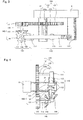
- FIG. 2 is a side view for showing the structure of the rotation assistance mechanism 100 of the first embodiment
- Fig. 3 is a top view thereof
- Fig. 4 is a front view thereof.
- the rotation assistance mechanism 100 is a mechanism for imparting momentum to the rotation of the axle 21 and rear wheel 13, and provided with an attraction unit 110 for giving a rotation force to the axle 21 and rear wheel 13 by the use of the attracting force of a magnet, a magnet drive unit 120 which drives the attraction unit 110, a shield unit 130 for strengthening or weakening the attracting force of the attraction unit 110, and a shield drive unit 140 for periodically driving the shield unit 130.
- the attraction unit 110 is a drive unit having a pair of magnetic members 112 and 112 with opposite poles facing each other.
- the attraction unit 110 includes a pair of upper and lower arm members 111 and 111 which support the pair of magnetic members 112 and 112 respectively and relatively pivot in order to widen and narrow the distance between the magnetic members 112 and 112 in the vertical direction.
- arm members 111 and 111 are vertically arranged as a pair approximately in a U-shaped fashion. Each of the arm members 111 and 111 is axially and pivotally supported on a rotating shaft 115 which is fixed to the rear end 9 of the rear fork 4. Then, the arm members 111 and 111 can pivot around the rotating shaft 115 to open in the vertical direction. On the other hand, a resilient member 113 is engaged between the arm members 111 and 111 in order to urge the arm members 111 and 111 located at a certain distance with this interposed resilient member 113.
- the magnet drive unit 120 is a driving mechanism which changes the distance between the pair of magnetic members 112 and 112. More specifically, the magnet drive unit 120 is provided with a rotary member 121 which rotates integrally with the axle 21 of the rear wheel 13, and a plane groove cam 122 for transmission of the rotation force of this rotary member 121.
- This rotary member 121 is a gear in the form of a disk which rotates around the axle 21 in a plane parallel with the rotation plane of the rear wheel 13.
- a guide groove 122a are carved on the outer surface of the rotary member 121 to form the plane groove cam 122 with coupling pins 123 formed of the arm members 111 respectively.
- the guide groove 122a is carved in the form of a sine wave closed as an endless loop.
- the distance between the guide groove 122a and the axle 21 as the center of rotation varies in accordance with the angle about the center so that two opposite points on the guide groove 122a symmetrically located with the axle 21 as the center move toward and away from each other in accordance with the central angle, resulting in the variable distance between the two points.
- the pair of coupling pins 123 and 123 are provided on and projected from the arm members 111 and 111 respectively toward the rotary member 121.
- the coupling pins 123 function as follower members as part of the plane groove cam 122, and inserted into the guide groove 122a and guided along the endless sine curve to widen and narrow the distance between the arm members 111. That is, the these coupling pins 123 and 123 are inserted into the guide groove 122a as described above at symmetric positions with reference to the axle 21 therebetween, guided through the guide groove 122a while the rotary member 121 is rotating, and thereby the arm members 111 and 111 are pivoted about the rotating shaft 115 in the vertical direction to change the distance between the pair of magnetic members 112 and 112 in predetermined cycles.
- the shield unit 130 includes an eccentric rotary plate 132 which is arranged in order to move towards and away between the pair of magnetic members 112 and 112, which are located opposite each other.
- the eccentric rotary plate 132 is provided with a pair of magnetic surfaces in the front and back sides thereof which are located to face the opposite surfaces 112a and 112a of the magnetic members 112 and 112 respectively such that the magnetic polarities of the magnetic surfaces 133 and 133 are opposite those of the corresponding surfaces 112a and 112a respectively.
- the eccentric rotary plate 132 is an elliptic plate member and driven to rotate around its rotation axis 131 which is decentered such that the pair of magnetic surfaces 133 and 133 on the front and back sides of the eccentric rotary plate 132 are advanced and retracted between the magnetic members 112 and 112 during rotation.
- the shield drive unit 140 is a driving mechanism which advances the shield unit 130 to between the pair of magnetic members 112 and 112 in predetermined cycles when the distance between the pair of magnetic members 112 and 112 is contracted, and retracts the shield unit 130 from between the pair of magnetic members 112 and 112 in the predetermined cycles when the distance between the pair of magnetic members 112 and 112 is expanded.
- the shield drive unit 140 is provided with a gear unit 141 to 144 which convert the rotation force of the rotary member 121 to the rotation of the eccentric rotary plate 132.
- the shield drive unit 140 consists of a gear 141 engaged with cut teeth carved on the outer circumference of the rotary member 121 which is rotating together with the rear wheel 13, a bevel gear 143 connected to the gear 141 through a shaft 142, a bevel gear 144 arranged to have a rotation plane perpendicular to the bevel gear 143, and the rotation axis 131 which transmits the rotation force of the bevel gear 144 to the eccentric rotary plate 132.
- the shield drive unit 140 thereby transmits the rotation force of the rear wheel 13 to the gear 143 through the rotary member 121, the gear 141 and the shaft 142, and the rotation force of the rear wheel 13 is converted to the rotation in a plane perpendicular to the rotation plane of the rear wheel 13 through the bevel gear 144 engaged with the bevel gear 143 to rotate the eccentric rotary plate 132 around the rotation axis 131.
- the eccentric rotary plate 132 is rotated in order that the magnetic surfaces 133 of the eccentric rotary plate 132 are advanced to between the pair of magnetic members 112 and 112 in predetermined cycles according to the rotation of the rear wheel 13 when the distance between the pair of arm members 111 and 111 is contracted, and retracted from between the pair of magnetic members 112 and 112 in the predetermined cycles when the distance between the pair of arm members 111 and 111 is expanded.
- FIG. 5 is a block diagram for schematically showing the operation of the rotation assistance mechanism 100.
- Figs. 6(a) and 6(b) are explanatory views for schematically showing the operation of the rotation assistance mechanism 100.
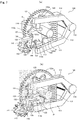
- Figs. 7(a) and 7(b) are perspective views for showing the rotation assistance mechanism 100 before and after operation.
- the rear wheel 13 of the bicycle 10 is rotated by turning the pedal 18 of the bicycle 10.
- the rotation of this rear wheel 13 is transmitted to the shield drive unit 140 and the magnet drive unit 120.
- the magnet drive unit 120 changes the distance between the pair of magnetic members 112 and 112 in the predetermined cycles when the rear wheel 13 is rotating.
- the rotary member 121 connected to the axle 21 of the rear wheel 13 also rotates together.
- the plane groove cam 122 consisting of the guide groove 122a and the coupling pins 123 of the arm member 111 is driven by this rotation force.
- the coupling pins 123 engaged with the guide groove 122a move toward and away from each other in accordance with the rotation angle of the rotary member 121 to widen and narrow the distance therebetween.
- this rotary member 121 is provided with the carved guide groove 122a into which the pair of coupling pins 123 and 123 are inserted at symmetric positions with reference to the axle 21 to form the plane groove cam 122.
- the guide groove 122a rotates together so that the pair of coupling pins 123 and 123 inserted into the guide groove 122a are guided along the profile of the guide groove 122a (in the form of an annular sine curve) and move toward and away from each other in accordance with the central angle to widen and narrow the distance the two points.
- the arm members 111 and 111 are then opened and closed around the rotating shaft 115 in the vertical direction by the pair of coupling pins 123 and 123 to change the distance between the pair of magnetic members 112 and 112 in predetermined cycles.
- the shield drive unit 140 advances and retracts the eccentric rotary plate 132 of the shield unit 130 between the pair of magnetic members 112 and 112 in synchronization with the rotation of the rear wheel 13.
- the rotation force generated by the rotation of the rear wheel 13 is first transmitted to the eccentric rotary plate 132.
- the rotary member 121 connected to the axle 21 of the rear wheel 13 rotates around the axle 21 as a center.
- the eccentric rotary plate 132 is therefore rotated to enter the magnetic surfaces 133 of the eccentric rotary plate 132 between the pair of magnetic members 112 and 112 with the timing when the distance between the pair of arm members 111 and 111 is narrowed.
- the magnetic surfaces 133 and 133 of the eccentric rotary plate 132 facing the pair of magnetic members 112 and 112 have the same polarities respectively to induce a repulsive magnetic force and widen the distance between the pair of arm members 111 and 111 as illustrated in Fig. 7(a) .
- the pair of coupling pins 123 and 123 moves away from each other along the guide groove in accordance with the central angle to increase the distance between the two points.
- the eccentric rotary plate 132 is rotated in order to move the magnetic surfaces 133 of the eccentric rotary plate 132 away from between the pair of magnetic members 112 and 112.
- the repulsive magnetic force is thereby removed, and an attracting force is generated by the magnetic members 112 and 112 which are arranged with their opposite poles facing each other so that the pair of arm members 111 and 111 attract each other. This operation is continuously repeated in this manner.
- the resilient member 113 is interposed between the pair of arm members 111 and 111, the distance between the pair of arm members 111 and 111 can be expanded and contracted also by the urging force of the resilient member 113.
- the eccentric rotary plate 132 of the present embodiment is provided with the pair of magnetic surfaces 133 and 133 on the front and back sides having the same polarities as the corresponding opposite surfaces of the pair of magnetic members 112 and 112 respectively, a repulsive magnetic force can be generated by advancing the eccentric rotary plate 132 between the pair of magnetic members 112 and 112 with the timing when the distance between the pair of arm members 111 and 111 is narrowed.
- an attractive force is generated between the pair of magnetic members 112 and 112 with opposite poles facing each other by retracting the eccentric rotary plate 132 from between the pair of magnetic members 112 and 112 with the timing when the distance between the pair of magnetic members 112 and 112 is widened.
- the distance between the pair of arm members 111 and 111 is expanded and contracted also by the urging force of the resilient member 113, and therefore it is possible to maintain the distance between the pair of arm members 111 and 111 in an appropriate range.
- an attraction unit 210 is constructed by arranging a number of magnetic members on a cylindrical side surface to generate an attracting force and a repulsive force with the magnetic members.
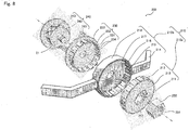
- Fig. 8 and Fig. 9 are perspective views for showing the structure of a rotation assistance mechanism 200 in accordance with the second embodiment as exploded views;
- Fig. 10 is a side view for showing the structure of the rotation assistance mechanism 200;
- Fig. 11 is a top view thereof;
- Fig. 12 is a front view thereof.
- like reference numbers indicate functionally similar elements as the above first embodiment unless otherwise specified, and therefore no redundant description is repeated.
- the rotation assistance mechanism 200 is a mechanism for imparting momentum to the rotation of the axle 21 and rear wheel 13, and provided with the attraction unit 210 for giving a rotation force to the rear wheel 13 through the axle 21 by the use of the attracting force of a magnet, a magnet drive unit consisting of the axle 21 and a stopper member 250 for driving the attraction unit 210, a shield unit 230 for strengthening or weakening the attracting force of the attraction unit 210, and a shield drive unit 240 for periodically driving the shield unit 230.
- the power source of the magnet drive unit and the shield drive unit 240 is the axle 21 which is the rotation axis of the rear wheel 13. The rotation force of the axle 21 is transmitted to an inner ring unit 210a through the stopper member 250 of the magnet drive unit, and transmitted directly to a rotary member 242 of the shield drive unit 240.
- the attraction unit 210 is a drive unit having magnetic members 213 and 215 which are paired with opposite poles facing each other.
- the attraction unit 210 includes the inner ring unit 210a in the form of a cylinder provided with a plurality of magnetic members 213 on its outer surface and the outer ring unit 210b in the form of a cylinder which is fitted inside the inner ring unit 210a and provided with a plurality of magnetic members 215 on its inner surface.
- the inner ring unit 210a has a wheel unit 212 in the form of a disk as a base component with a center hole 211 in the center position of this wheel unit 212.
- the wheel unit 212 is fixed to the axle 21 which is inserted through the center hole 211 and rotatable integrally with the axle 21.
- an indent section 252 is formed on the outer surface of the wheel unit 212 in the same profile as the stopper member 250, which is threaded on the axle 21 and fitted to the indent section 252 so that the wheel unit 212 and the stopper member 250 are integrally joined to transmit the rotation force of the axle 21 to the wheel unit 212.
- the inner ring unit 210a move the magnetic members 213 arranged on the outer surface thereof in relation to the outer ring unit 210b.
- the outer ring unit 210b is provided with a housing section 218 in a bottomed cylindrical shape having a center hole 217 in the center position of its bottom portion through which the axle 21 is inserted in order that the outer ring unit 210b is separated from the rotation of the rear wheel 13. More specifically, the housing section 218 of the outer ring unit 210b is fixed to the main body of a bicycle through frame members 214 and 214 which are fixed to the rear end 9 of the bicycle and connected to the opposite sides of the housing section 218 in order that the axle 21 rotates in an idling condition as seen from the center hole 217 in order not to transmit the rotation of the rear wheel 13.
- the outer ring unit 210b has a hollow space with an outer opening to house the inner ring unit 210a, a number of the magnetic members 215 which are annularly arranged in the inner surface of the housing section 218, and a number of shield apertures 216 which are annularly arranged along the perimeter of the bottom surface of the housing section 218 in correspondence with the arrangement of the magnetic members 215 respectively.
- the housing section 218 is fixed to the body frame of the bicycle by the frame members 214.
- the magnet drive unit of the present embodiment consists of the axle 21 and the stopper member 250, and functions as a driving mechanism which changes the distance between the pair of magnetic members 213 and 215 in predetermined cycles by the rotation of the rear wheel 13. More specifically, the wheel unit 212 is rotated by the stopper member 250 which rotates integrally with the axle 21 of the rear wheel 13.
- the wheel unit 212 as a rotary member is a cylindrical member which is connected to the axle 21 and axially supports the inner ring unit 210a as discussed above. Then, when the wheel unit 212 rotates by the rotation of the rear wheel 13, the inner ring unit 210a rotates in relation to the outer ring unit 210b.
- the housing section 218 and the wheel unit 212 are spacially located close to each other, but mechanically separated from each other by a bearing or the like sliding mechanism (not shown in the figure) so that the rotation force of the wheel unit 212 is not transmitted to the housing section 218.
- the shield unit 230 is provided with projection members 231 which are arranged to project toward the shield apertures 216 and can be advanced between the outer surface of the inner ring unit 210a and the inner surface of the outer ring unit 210b.
- the projection member 231 has magnetic surfaces 234 on the front and back sides thereof.
- the magnetic surface 234 has opposite polarities on the front and back sides.
- the shield drive unit 240 is a driving mechanism which advances the magnetic surfaces 234 of the projection members 231 between the magnetic members 213 of the inner ring unit 210a and the magnetic members 215 of the outer ring unit 210b in predetermined cycles with the timing when the magnetic members 215 of the outer ring unit 210b come close to the magnetic members 213 of the inner ring unit 210a with opposite polarities respectively and retracts the magnetic surfaces 234 of the projection members 231 from between the magnetic members 213 of the inner ring unit 210a and the magnetic members 215 of the outer ring unit 210b in the predetermined cycles with the timing when the magnetic members 215 of the outer ring unit 210b come close to the magnetic members 213 of the inner ring unit 210a with the same polarities respectively.
- the shield drive unit 240 consists of a rotary member 242 in the form of a column and four coupling pins 241.
- the rotary member 242 is a cylindrical piece connected to the axle 21 and provided with a flange 240a in the form of a disk for protecting the mechanism, and fixed to the axle 21 to rotate by following the axle 21.
- a guide groove 243 is carved on the outer peripheral surface of the rotary member 242 to form a cylindrical groove cam which converts the rotation force of the rotary member 242 to the forward and backward motion of the shield unit 230. More specifically, this guide groove 243 is carved in the form of a sine wave closed as an endless loop such that the distance to the outer ring unit 210b varies in accordance with the position on the axle 21. The distance to the outer ring unit 210b at four points on the guide groove 243 symmetrically located with the axle 21 as the center is widened and narrowed in accordance with the position on the axle 21.
- the four coupling pins 241 are rod members projecting from the base 233 of the shield unit 230.
- the four coupling pins 241 project from the side opposite to the side from which the projection member 231 are projecting.
- the base 233 is a plate member in the form of a disk with a center hole 232 which is opened through the front and back sides and through which the axle 21 is inserted.
- the base 233 is axially supported on the rotary member 242 through the coupling pins 241.
- This center hole 232 has an inner diameter which is slightly larger than the diameter of the axle 21 so that the axle 21 can rotate in this center hole 232 without transmitting the rotation of the axle 21 to the base 233.
- the base 233 can slidably move back and forward together with the coupling pins 241 and the projection members 231 only in the axial direction of the axle 21.
- the four coupling pins 241 are inserted into the guide groove 243 as described above at four points on a concentric circle around the axle 21 as a center, guided through the guide groove 243 while the rotary member 242 is rotating, and thereby move the shield unit 230 close to and away from the outer ring unit 210b so that the projection members 231 are advanced to and retracted from between the pair of magnetic members 213 and 215 in predetermined cycles.
- the magnetic surfaces 234 of the projection members 231 are advanced between the magnetic members 213 of the inner ring unit 210a and the magnetic members 215 of the outer ring unit 210b with the timing when the magnetic members 215 of the outer ring unit 210b come close to the magnetic members 213 of the inner ring unit 210a with opposite polarities respectively, and retracted from between the magnetic members 213 of the inner ring unit 210a and the magnetic members 215 of the outer ring unit 210b with the timing when the magnetic members 215 of the outer ring unit 210b come close to the magnetic members 213 of the inner ring unit 210a with the same polarities respectively.
- Fig. 13 shows perspective views of the rotation assistance mechanism of the second embodiment before and after operation.
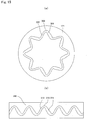
- Fig. 14 shows views for explaning the positional relationship of the magnetic members facing each other in accordance with the second embodiment.
- the rear wheel 13 of the bicycle 10 is rotated by turning the pedal 18 of the bicycle 10.
- the rotation of this rear wheel 13 is transmitted to the shield drive unit 240 and the magnet drive unit 220.
- the wheel unit 212 of the attraction unit 210 connected to the axle 21 of the rear wheel 13 also rotates around the axle 21.
- This wheel unit 212 is fixed to the axle 21 with the stopper member 250 such as a nut, and rotates to move the magnetic members 213 arranged on the peripheral surface in relation to the outer ring unit 210b.
- the housing section 218 of the outer ring unit 210b and the wheel unit 212 of the inner ring unit 210a are mechanically separated from each other so that the rotation force of the wheel unit 212 is not transmitted to the housing section 218.
- the shield drive unit 240 converts the rotation force of the rotary member 242 to the forward and backward motion of the projection member 231. More specifically, the shield drive unit 240 advances the magnetic surfaces 234 of the projection members 231 between the magnetic members 213 of the inner ring unit 210a and the magnetic members 215 of the outer ring unit 210b with the timing when the magnetic members 215 of the outer ring unit 210b come close to the magnetic members 213 of the inner ring unit 210a with opposite polarities respectively.
- the rotary member 242 axially supported on the axle 21 rotates in association with the rotation of the rear wheel 13 to advance this projection member 231. Since the rotary member 242 is provided with the guide groove 243 into which the four coupling pins 241 are inserted at symmetric positions with reference to the axle 21, as illustrated in Fig. 13(a) , the four coupling pins 241 inserted into this guide groove 243 are guided by the guide groove 243, and therefore the distance to the outer ring unit 210b is widened and narrowed when the rotary member 242 rotates.
- the base 233 connected to the four coupling pins 241 is shifted also toward the outer ring unit 210b.
- the projection members 231 of the shield unit 230 are thereby inserted into the shield apertures 216, and enter between the magnetic member 213 of the inner ring unit 210a and the magnetic member 215 of the outer ring unit 210b.
- the positional relationship between the magnetic member 213 of the inner ring unit 210a and the magnetic member 215 of the outer ring unit 210b is such that the magnetic members 215 of the outer ring unit 210b come close to the magnetic members 213 of the inner ring unit 210a with opposite polarities respectively.
- the magnetic surfaces 234 of the projection members 231 are advanced between the magnetic members 213 of the inner ring unit 210a and the magnetic members 215 of the outer ring unit 210b so that the magnetic members 213 and the magnetic members 215 face the magnetic surfaces 234 of the projection members 231 with the same polarities as illustrated in Fig. 14(b) to induce repulsive magnetic forces therebetween.
- the shield drive unit 240 retracts the magnetic surfaces 234 of the projection members 231 from between the magnetic members 213 of the inner ring unit 210a and the magnetic members 215 of the outer ring unit 210b with the timing when the magnetic members 215 of the outer ring unit 210b come close to the magnetic members 213 of the inner ring unit 210a with the same polarities respectively.
- the retraction motion of the projection members 231 widens the distance to the outer ring unit 210b when the rotary member 242 rotates while the four coupling pins 241 inserted into the guide groove 243 are guided by the guide groove 243 as illustrated in Fig. 13(a) . Then, when the distance to the outer ring unit 210b is widened, the shield unit 230 connected to the four coupling pins 241 moves away from the outer ring unit 210b. In this case, as illustrated in Fig. 13(a) , the projection members 231 of the shield unit 230 are retracted from the shield apertures 216 to leave the space between the magnetic members 213 of the inner ring unit 210a and the magnetic members 215 of the outer ring unit 210b.
- the positional relationship between the magnetic members 213 of the inner ring unit 210a and the magnetic members 215 of the outer ring unit 210b is such that the magnetic members 215 of the outer ring unit 210b come close to the magnetic members 213 of the inner ring unit 210a with the same polarities respectively.
- the magnetic surfaces 234 of the projection members 231 are retracted from between the magnetic members 213 of the inner ring unit 210a and the magnetic members 215 of the outer ring unit 210b so that the magnetic members 213 and the magnetic members 215 face each other with the same polarities as illustrated in Fig. 14(a) to induce repulsive magnetic forces therebetween. This operation is continuously repeated in this manner.
- the shield unit 230 of the present embodiment is provided with the plurality of projection members 231 having the magnetic surfaces 234 on the front and back sides thereof respectively, a repulsive magnetic force can be generated by advancing the magnetic surfaces 234 of the projection members 231 between the magnetic members 213 of the inner ring unit 210a and the magnetic members 215 of the outer ring unit 210b with the timing when the magnetic members 215 of the outer ring unit 210b come close to the magnetic members 213 of the inner ring unit 210a with opposite polarities respectively in synchronization with the rotation of the rear wheel 13.
- an attractive force is generated between the paired magnetic members 213 and 215 with opposite poles facing each other by retracting the magnetic surfaces 234 of the projection members 231 from between the magnetic members 213 of the inner ring unit 210a and the magnetic members 215 of the outer ring unit 210b in the predetermined cycles with the timing when the magnetic members 215 of the outer ring unit 210b come close to the magnetic members 213 of the inner ring unit 210a with the same polarities respectively.
- a number of magnetic members 213 and 215 are arranged on the cylindrical side surfaces respectively as the attraction unit 210 to generate a stronger attracting force and a repulsive force with the magnetic members.
- the present invention is not limited to the above embodiment, but it is possible to add a variety of modification thereto.
- the plane groove cam and the cylindrical groove cam into which the coupling pins are inserted can be modified.
- groove cams 300 and 310 having waveforms which are irregularly continued may be used in place of the groove cams of the first embodiment and the second embodiment which have simple cosine waves respectively. These waveforms behave a cosine waveform with the timing when the pair magnetic members depart from each other, and behave a waveform having a wider groove when the pair magnetic members attract each other.
- the groove cams are designed such that the guide grooves 301 and 311 have larger widths when the coupling pins are moved by the repulsive force of the magnetic members than the guide grooves 302 and 312 have when the coupling pins are moved by the attracting force of the magnetic members.
- the larger width makes it easy to follow the pedaling motion of the user and absorb the resistance of the cam to the varying rotational speed of a wheel.
Description
- The present invention relates to a rotation assistance mechanism and a rotating power mechanism equipped with same which can be generally applied to an apparatus which operates with a rotational driving force transmitted from a power source, and further relates to a bicycle, an electric fan, a belt conveyor, an escalator, a kneading machine, and a sign pole, which are equipped with the rotation assistance mechanism and the rotating power mechanism.
- Conventionally, machines driven by rotating a rotation shaft have been used, such as bicycles, automobiles, electric fans, belt conveyors, escalators and kneading machines. For example, a user drives a bicycle to run on the ground by turning a pedal which is a rotational driving source to generate propulsive power by transmitting a rotational driving force therefrom to the front and rear wheels through a chain. The bicycles as used in this manner include the so-called assist bicycle equipped with an electric motor as a rotational driving source and a battery to reduce the efforts required for turning a pedal when starting or climbing up a slope. The pedaling force exerted on this assist bicycle by human power is detected by a detection unit (torque sensor or the like), which outputs a signal indicative of the pedaling force to a control device which drives the electric motor in accordance with the pedaling force (for example, refer to the Patent Document 1).
- On the other hand, another example of the machines which are rotationally driven is an electric fan equipped with a blade assembly which is provided with a plurality of blades and connected to the rotation shaft of an electric motor which is a power source. This electric fan can generate an air flow by transmitting the driving force of the electric motor to the vanes and rotating the blade assembly with the driving force (for example, refer to Patent Document 2).
-
- [Patent Document 1]
Japanese Patent Published Application No.09-123981 - [Patent Document 2]
Japanese Patent Published Application No.2010-024888 - However, generally speaking in the case of the machines which are rotationally driven as described above, a driving force is directly transmitted from a power source which is directly connected to a rotation shaft so that, when the power source is stopped, the transmitted driving force is lost. From this fact, conventionally, an electric power of no lower than a predetermined level has to be constantly supplied in order to successively operate the device.
- For example, since a drive motor mounted on an assist bicycle has to be driven while turning a wheel, there is a problem that power consumption increases so that the battery is frequently used up. Such an assist bicycle with a run-out charged battery is simply heavy and conversely increases the driver's burden because of the battery and the motor which increase the total weight of the bicycle. Furthermore, in the case of an electric fan, since a motor has to be driven while a blade assembly is rotating, there is also a problem that power consumption increases.
- In order to solve the problem as described above, it is an object of the present invention to provide a rotation assistance mechanism, a rotating power mechanism equipped with the rotation assistance mechanism, and an electric fan, a belt conveyor, an escalator, a kneading machine and a sign pole which are provided with the rotation assistance mechanism respectively, wherein a driving force is transmitted from a power source to rotationally drive an apparatus through a rotation axis to which momentum is imparted by the rotation assistance mechanism to assist the rotation thereof and improve the usefulness.
- In order to accomplish the object as described above, the present invention provides a rotation assistance mechanism according to appended claim 1.
- In accordance with the invention as described above, since the shield unit is provided with the pair of magnetic surfaces facing the pair of magnetic members respectively and having magnetic polarities which are opposite to those of the corresponding surfaces of the pair of magnetic members respectively, the shield drive unit generates a repulsive magnetic force by advancing the shield unit to between the pair of magnetic members when the distance between the pair of magnetic members is contracted, and an attracting force between the pair of magnetic members with opposite poles facing each other by retracting the shield unit from between the pair of magnetic members when the distance between the pair of magnetic members is expanded. As a result, it is possible to continuously generate the attractive force and the repulsive force by the magnetic members, and impart momentum to the rotation of the rotation axis. As a result, for example, by providing a bicycle with the rotation assistance mechanism, it is possible to pedal without requiring efforts and reduce the weight and cost of a bicycle even without installing an electric motor. Also, in the case where the rotation assistance mechanism is installed in a bicycle or an electric fan equipped with an electric motor, since momentum can be imparted to the rotation of the rotation axis of the electric motor, the rotation force is not reduced even when supplying electric power only in an intermittent manner, and thereby it is possible to reduce the power consumption. Furthermore, it is possible to lower the occurrence frequency of exhaustion of the battery of an assist bicycle.
- In the case of the above invention, it is preferred that the attraction unit is provided with a pair of arm members which support the pair of magnetic members respectively and relatively pivot in order to widen and narrow the distance therebetween, that the magnet drive unit comprising: a rotary member configured to rotate together with the rotation axis; a plane groove cam formed with a guide groove which is carved on the surface of the rotary member; and a pair of coupling pins projected to the rotary member from the arm members respectively and guided by the guide groove to widen and narrow the distance between the arm members, that the shield unit has an eccentric rotary plate which is rotated around a decentered rotation axis and provided with the pair of magnetic surfaces on the front and back sides thereof, that the shield drive unit has a gear unit which convert the rotation force of the rotary member to the rotation of the eccentric rotary plate, and that the shield drive unit advances the magnetic surfaces of the eccentric rotary plate to between the pair of magnetic members in predetermined cycles when the distance between the pair of arm members is contracted, and retracts the magnetic surfaces of the eccentric rotary plate from between the pair of magnetic members in the predetermined cycles when the distance between the pair of arm members is expanded.
- In this case, since the eccentric rotary plate is provided with the pair of magnetic surfaces facing the pair of magnetic members respectively and having magnetic polarities which are opposite to those of the corresponding surfaces of the pair of magnetic members respectively, the shield drive unit generates a repulsive magnetic force by advancing the eccentric rotary plate to between the pair of magnetic members when the distance between the arm members is contracted, and an attracting force between the pair of magnetic members with opposite poles facing each other by retracting the eccentric rotary plate from between the pair of magnetic members when the distance between the pair of magnetic members is expanded. In accordance with the present invention as described above, since momentum can be imparted to the rotation of the rotation axis by continuously generating an attracting force and a repulsive force with the magnetic members, it is possible to assist the rotation thereof and improve the usefulness.
- In the case of the above invention, it is preferred that the attraction unit comprising: an inner ring unit in the form of a cylinder which rotates together with the rotation of the rotation axis and provided with a plurality of magnetic members arranged on its outer surface; and an outer ring unit in the form of a cylinder which is fitted inside the inner ring unit and provided with a plurality of magnetic members arranged on its inner surface, that the magnet drive unit rotates the inner ring unit in relation to the outer ring unit by the rotation of the rotation axis, that the shield unit is provided with a plurality of projection members having the magnetic surfaces in the front and back sides thereof, and moves the projection members forward and backward between the outer surface of the inner ring unit and the inner surface of the outer ring unit, that the shield drive unit includes a cylindrical groove cam which converts the rotation force of the rotary member to the forward and backward motion of the projection member, and that the shield drive unit advances the magnetic surfaces of the projection members between the magnetic members of the inner ring unit and the magnetic members of the outer ring unit in predetermined cycles with the timing when the magnetic members of the outer ring unit come close to the magnetic members of the inner ring unit with opposite polarities respectively and retracts the magnetic surfaces of the projection members from between the magnetic members of the inner ring unit and the magnetic members of the outer ring unit in the predetermined cycles with the timing when the magnetic members of the outer ring unit come close to the magnetic members of the inner ring unit with the same polarities respectively.
- In this case, since the shield unit of the present embodiment is provided with the plurality of projection members having the magnetic surfaces on the front and back sides thereof respectively, a repulsive magnetic force can be generated by advancing the magnetic surfaces of the projection members between the magnetic members of the inner ring unit and the magnetic members of the outer ring unit with the timing when the magnetic members of the outer ring unit come close to the magnetic members of the inner ring unit with opposite polarities respectively in synchronization with the rotation of the rotation axis. Furthermore, an attractive force is generated between the paired magnetic members and with opposite poles facing each other by retracting the magnetic surfaces of the projection members from between the magnetic members of the inner ring unit and the magnetic members of the outer ring unit in the predetermined cycles with the timing when the magnetic members of the outer ring unit come close to the magnetic members of the inner ring unit with the same polarities respectively. As a result, it is possible to continuously generate the attractive force and the repulsive force by the magnetic members, impart momentum to the rotation of the rear wheel, and therefore improve the usefulness by assisting the rotation thereof. Particularly, in accordance with the present invention, the attraction unit is constructed by arranging a number of magnetic members on a cylindrical side surface to further generate an attracting force and a repulsive force with the magnetic members, and therefore it is possible to further impart momentum to the rotation of the rotation axis.
- As has been discussed above, in accordance with the present invention applied to the apparatus which is rotationally driven by the driving force transmitted from a power source through a rotation axis, it is possible to assist the rotation thereof and improve the usefulness.
-
-
Fig. 1 is a schematic representation showing the overall configuration of a bicycle in accordance with a first embodiment. -
Fig. 2 is a side view for showing the structure of the rotation assistance mechanism in accordance with the first embodiment. -
Fig. 3 is a top view for showing the structure of the rotation assistance mechanism in accordance with the first embodiment. -
Fig. 4 is a front view for showing the structure of the rotation assistance mechanism in accordance with the first embodiment. -
Fig. 5 is a block diagram for schematically showing the operation of the rotation assistance mechanism in accordance with the first embodiment. -
Fig. 6(a) and Fig. 6(b) are explanatory views for schematically showing the operation of the rotation assistance mechanism in accordance with the first embodiment. -
Fig. 7(a) and Fig. 7(b) are perspective views for showing the rotation assistance mechanism before and after operation in accordance with the first embodiment. -
Fig. 8 is exploded perspective views for showing the structure of a rotation assistance mechanism in accordance with a second embodiment. -
Fig. 9 is exploded perspective views for showing the structure of a rotation assistance mechanism in accordance with the second embodiment. -
Fig. 10 is a side view for showing the structure of the rotation assistance mechanism in accordance with the second embodiment. -
Fig. 11 is a top view for showing the structure of the rotation assistance mechanism in accordance with the second embodiment. -
Fig. 12 is a front view for showing the structure of the rotation assistance mechanism in accordance with the second embodiment. -
Fig. 13 shows perspective views of the rotation assistance mechanism of the second embodiment before and after operation in accordance with the second embodiment. -
Fig. 14 shows views for explaining the positional relationship of the magnetic members facing each other in accordance with the second embodiment. -
Fig. 15 shows views for explaining groove cams in accordance with modification examples. - In what follows, an embodiment of a rotation assistance mechanism in accordance with the present invention will be explained in detail. Meanwhile, in the case of the present embodiment, an example will be explained in the case where the rotation assistance mechanism of the present invention is applied to a wheel of a
bicycle 10. However, the present invention can be applied also to all the machines which are rotationally driven such as the wheels of bicycles and automobiles, water wheels, windmills, and the machines provided with generators such as electric fans, belt conveyors, escalators, kneading machines and the like. -
Fig. 1 is a schematic representation showing the overall configuration of abicycle 10 in accordance with a first embodiment of the present invention. Thebicycle 10 of the present embodiment includes a body frame 1 having ahead tube 2 located in the front side of the body frame 1, adown tube 3 extending from thehead tube 2 in the rear-downward direction, a rear fork 4 connected to thedown tube 3 and extending in the rear direction, and aseat post 5 rising upward from the lowermost end of thedown tube 3. - A front fork 6 is rotatably supported on the
head tube 2. Also, the lower end of the front fork 6 is provided with ahub 22 through which the entirety of afront wheel 7 is axially supported on an axle. Furthermore, the upper end of the front fork 6 is provided with ahandlebar 8. Meanwhile, although not shown in the figure, thehandlebar 8 is provided with brake levers for the front and rear wheels. Cables are extracted from the brake levers and linked with a front wheel brake and a rear wheel brake respectively. - A
crank shaft 14 extending in the lateral direction of the body frame is supported at the crossed section between thedown tube 3 and theseat post 5, and connected to thepedals 18 throughcranks 17. Thecrank shaft 14 is connected to a drivingsprocket 19 so that the pedal force exerted on thepedals 18 is transmitted to the drivingsprocket 19. A chain 11 is spanned between the drivingsprocket 19 and anon-driven sprocket 20 which is fixed to theaxle 21 of arear wheel 13. - The
seat post 5 is provided with asupport shaft 16 having an upper end on which aseat 15 is mounted in order that the height of theseat 15 can be adjusted. Also, a pair of left and right stays 12 are connected to the upper end of theseat post 5, extending in the rear-downward direction, and joined with the rear fork 4 near the lower end thereof. Therear wheel 13 is supported on theaxle 21 which is horizontally extending in the right and left direction of the body frame on arear end 9 where the rear fork 4 and thestays 12 are crossing and connected to each other. Therotation assistance mechanism 100 of the present embodiment is supported by therear end 9 and located coaxially with theaxle 21 which is the rotation axis of therear wheel 13. - Next, the configuration of the
rotation assistance mechanism 100 will be explained.Fig. 2 is a side view for showing the structure of therotation assistance mechanism 100 of the first embodiment,Fig. 3 is a top view thereof, andFig. 4 is a front view thereof. - As shown in
Fig. 2 through Fig. 4 , therotation assistance mechanism 100 is a mechanism for imparting momentum to the rotation of theaxle 21 andrear wheel 13, and provided with anattraction unit 110 for giving a rotation force to theaxle 21 andrear wheel 13 by the use of the attracting force of a magnet, amagnet drive unit 120 which drives theattraction unit 110, ashield unit 130 for strengthening or weakening the attracting force of theattraction unit 110, and ashield drive unit 140 for periodically driving theshield unit 130. - The
attraction unit 110 is a drive unit having a pair ofmagnetic members attraction unit 110 includes a pair of upper andlower arm members magnetic members magnetic members - These
arm members arm members rotating shaft 115 which is fixed to therear end 9 of the rear fork 4. Then, thearm members rotating shaft 115 to open in the vertical direction. On the other hand, aresilient member 113 is engaged between thearm members arm members resilient member 113. - The
magnet drive unit 120 is a driving mechanism which changes the distance between the pair ofmagnetic members magnet drive unit 120 is provided with arotary member 121 which rotates integrally with theaxle 21 of therear wheel 13, and aplane groove cam 122 for transmission of the rotation force of thisrotary member 121. Thisrotary member 121 is a gear in the form of a disk which rotates around theaxle 21 in a plane parallel with the rotation plane of therear wheel 13. - In addition, a
guide groove 122a are carved on the outer surface of therotary member 121 to form theplane groove cam 122 withcoupling pins 123 formed of thearm members 111 respectively. Theguide groove 122a is carved in the form of a sine wave closed as an endless loop. The distance between theguide groove 122a and theaxle 21 as the center of rotation varies in accordance with the angle about the center so that two opposite points on theguide groove 122a symmetrically located with theaxle 21 as the center move toward and away from each other in accordance with the central angle, resulting in the variable distance between the two points. - Furthermore, the pair of coupling pins 123 and 123 are provided on and projected from the
arm members rotary member 121. The coupling pins 123 function as follower members as part of theplane groove cam 122, and inserted into theguide groove 122a and guided along the endless sine curve to widen and narrow the distance between thearm members 111. That is, the these coupling pins 123 and 123 are inserted into theguide groove 122a as described above at symmetric positions with reference to theaxle 21 therebetween, guided through theguide groove 122a while therotary member 121 is rotating, and thereby thearm members rotating shaft 115 in the vertical direction to change the distance between the pair ofmagnetic members - The
shield unit 130 includes an eccentricrotary plate 132 which is arranged in order to move towards and away between the pair ofmagnetic members rotary plate 132 is provided with a pair of magnetic surfaces in the front and back sides thereof which are located to face theopposite surfaces magnetic members magnetic surfaces surfaces rotary plate 132 is an elliptic plate member and driven to rotate around itsrotation axis 131 which is decentered such that the pair ofmagnetic surfaces rotary plate 132 are advanced and retracted between themagnetic members - The
shield drive unit 140 is a driving mechanism which advances theshield unit 130 to between the pair ofmagnetic members magnetic members shield unit 130 from between the pair ofmagnetic members magnetic members - Specifically, the
shield drive unit 140 is provided with agear unit 141 to 144 which convert the rotation force of therotary member 121 to the rotation of the eccentricrotary plate 132. Namely, theshield drive unit 140 consists of agear 141 engaged with cut teeth carved on the outer circumference of therotary member 121 which is rotating together with therear wheel 13, abevel gear 143 connected to thegear 141 through ashaft 142, abevel gear 144 arranged to have a rotation plane perpendicular to thebevel gear 143, and therotation axis 131 which transmits the rotation force of thebevel gear 144 to the eccentricrotary plate 132. - The
shield drive unit 140 thereby transmits the rotation force of therear wheel 13 to thegear 143 through therotary member 121, thegear 141 and theshaft 142, and the rotation force of therear wheel 13 is converted to the rotation in a plane perpendicular to the rotation plane of therear wheel 13 through thebevel gear 144 engaged with thebevel gear 143 to rotate the eccentricrotary plate 132 around therotation axis 131. By this configuration, the eccentricrotary plate 132 is rotated in order that themagnetic surfaces 133 of the eccentricrotary plate 132 are advanced to between the pair ofmagnetic members rear wheel 13 when the distance between the pair ofarm members magnetic members arm members - The operation of the
rotation assistance mechanism 100 having the configuration as described above will be explained in the following description.Fig. 5 is a block diagram for schematically showing the operation of therotation assistance mechanism 100.Figs. 6(a) and 6(b) are explanatory views for schematically showing the operation of therotation assistance mechanism 100.Figs. 7(a) and 7(b) are perspective views for showing therotation assistance mechanism 100 before and after operation. - First, the
rear wheel 13 of thebicycle 10 is rotated by turning thepedal 18 of thebicycle 10. The rotation of thisrear wheel 13 is transmitted to theshield drive unit 140 and themagnet drive unit 120. Themagnet drive unit 120 changes the distance between the pair ofmagnetic members rear wheel 13 is rotating. Specifically speaking, when therear wheel 13 rotates, therotary member 121 connected to theaxle 21 of therear wheel 13 also rotates together. Theplane groove cam 122 consisting of theguide groove 122a and the coupling pins 123 of thearm member 111 is driven by this rotation force. The coupling pins 123 engaged with theguide groove 122a move toward and away from each other in accordance with the rotation angle of therotary member 121 to widen and narrow the distance therebetween. - More specifically, this
rotary member 121 is provided with the carvedguide groove 122a into which the pair of coupling pins 123 and 123 are inserted at symmetric positions with reference to theaxle 21 to form theplane groove cam 122. When therotary member 121 rotates as part of thisplane groove cam 122, theguide groove 122a rotates together so that the pair of coupling pins 123 and 123 inserted into theguide groove 122a are guided along the profile of theguide groove 122a (in the form of an annular sine curve) and move toward and away from each other in accordance with the central angle to widen and narrow the distance the two points. Thearm members rotating shaft 115 in the vertical direction by the pair of coupling pins 123 and 123 to change the distance between the pair ofmagnetic members - On the other hand, the
shield drive unit 140 advances and retracts the eccentricrotary plate 132 of theshield unit 130 between the pair ofmagnetic members rear wheel 13. The rotation force generated by the rotation of therear wheel 13 is first transmitted to the eccentricrotary plate 132. Specifically, when therear wheel 13 rotates, therotary member 121 connected to theaxle 21 of therear wheel 13 rotates around theaxle 21 as a center. Then, through the rotation force of thisrotary member 121, the rotation force of therear wheel 13 is transmitted to thegear 143 through therotary member 121, thegear 141 and theshaft 142, and the rotation force of therear wheel 13 is converted to the rotation in a plane perpendicular to the rotation plane of therear wheel 13 through thebevel gear 144 engaged with thebevel gear 143 to transmit the rotation force of thebevel gear 144 to therotation axis 131 and rotate the eccentricrotary plate 132. - The eccentric
rotary plate 132 is therefore rotated to enter themagnetic surfaces 133 of the eccentricrotary plate 132 between the pair ofmagnetic members arm members magnetic surfaces rotary plate 132 facing the pair ofmagnetic members arm members Fig. 7(a) . - When the
arm members arm members rotary plate 132 is rotated in order to move themagnetic surfaces 133 of the eccentricrotary plate 132 away from between the pair ofmagnetic members magnetic members arm members - Incidentally, since the
resilient member 113 is interposed between the pair ofarm members arm members resilient member 113. - As has been discussed above, since the eccentric
rotary plate 132 of the present embodiment is provided with the pair ofmagnetic surfaces magnetic members rotary plate 132 between the pair ofmagnetic members arm members magnetic members rotary plate 132 from between the pair ofmagnetic members magnetic members magnetic members rear wheel 13, and therefore lessen the pedaling burden. Also, since no electric motor is used, it is possible to reduce the weight and cost of a bicycle. - Furthermore, in accordance with the present embodiment, the distance between the pair of
arm members resilient member 113, and therefore it is possible to maintain the distance between the pair ofarm members - Next, a second embodiment of the present invention will be explained. In the case of the first embodiment as described above, the pair of
arm members attraction unit 110 in the configuration that momentum is imparted to the rotation of the wheel by the attracting force and the repulsive force generated by the two magnetic members. However, in the case of the present embodiment, anattraction unit 210 is constructed by arranging a number of magnetic members on a cylindrical side surface to generate an attracting force and a repulsive force with the magnetic members. -
Fig. 8 andFig. 9 are perspective views for showing the structure of arotation assistance mechanism 200 in accordance with the second embodiment as exploded views;Fig. 10 is a side view for showing the structure of therotation assistance mechanism 200;Fig. 11 is a top view thereof; andFig. 12 is a front view thereof. Meanwhile, in the description of the present embodiment, like reference numbers indicate functionally similar elements as the above first embodiment unless otherwise specified, and therefore no redundant description is repeated. - As illustrated in
Fig. 8 andFig. 9 , therotation assistance mechanism 200 is a mechanism for imparting momentum to the rotation of theaxle 21 andrear wheel 13, and provided with theattraction unit 210 for giving a rotation force to therear wheel 13 through theaxle 21 by the use of the attracting force of a magnet, a magnet drive unit consisting of theaxle 21 and astopper member 250 for driving theattraction unit 210, ashield unit 230 for strengthening or weakening the attracting force of theattraction unit 210, and ashield drive unit 240 for periodically driving theshield unit 230. Also in the case of the present embodiment, the power source of the magnet drive unit and theshield drive unit 240 is theaxle 21 which is the rotation axis of therear wheel 13. The rotation force of theaxle 21 is transmitted to aninner ring unit 210a through thestopper member 250 of the magnet drive unit, and transmitted directly to arotary member 242 of theshield drive unit 240. - The
attraction unit 210 is a drive unit havingmagnetic members attraction unit 210 includes theinner ring unit 210a in the form of a cylinder provided with a plurality ofmagnetic members 213 on its outer surface and theouter ring unit 210b in the form of a cylinder which is fitted inside theinner ring unit 210a and provided with a plurality ofmagnetic members 215 on its inner surface. - The
inner ring unit 210a has awheel unit 212 in the form of a disk as a base component with acenter hole 211 in the center position of thiswheel unit 212. Thewheel unit 212 is fixed to theaxle 21 which is inserted through thecenter hole 211 and rotatable integrally with theaxle 21. More specifically, anindent section 252 is formed on the outer surface of thewheel unit 212 in the same profile as thestopper member 250, which is threaded on theaxle 21 and fitted to theindent section 252 so that thewheel unit 212 and thestopper member 250 are integrally joined to transmit the rotation force of theaxle 21 to thewheel unit 212. Then, when thewheel unit 212 rotates around theaxle 21 in association with the rotation of therear wheel 13, theinner ring unit 210a move themagnetic members 213 arranged on the outer surface thereof in relation to theouter ring unit 210b. - On the other hand, the
outer ring unit 210b is provided with ahousing section 218 in a bottomed cylindrical shape having acenter hole 217 in the center position of its bottom portion through which theaxle 21 is inserted in order that theouter ring unit 210b is separated from the rotation of therear wheel 13. More specifically, thehousing section 218 of theouter ring unit 210b is fixed to the main body of a bicycle throughframe members rear end 9 of the bicycle and connected to the opposite sides of thehousing section 218 in order that theaxle 21 rotates in an idling condition as seen from thecenter hole 217 in order not to transmit the rotation of therear wheel 13. On the other hand, theouter ring unit 210b has a hollow space with an outer opening to house theinner ring unit 210a, a number of themagnetic members 215 which are annularly arranged in the inner surface of thehousing section 218, and a number ofshield apertures 216 which are annularly arranged along the perimeter of the bottom surface of thehousing section 218 in correspondence with the arrangement of themagnetic members 215 respectively. Thehousing section 218 is fixed to the body frame of the bicycle by theframe members 214. - The magnet drive unit of the present embodiment consists of the
axle 21 and thestopper member 250, and functions as a driving mechanism which changes the distance between the pair ofmagnetic members rear wheel 13. More specifically, thewheel unit 212 is rotated by thestopper member 250 which rotates integrally with theaxle 21 of therear wheel 13. Thewheel unit 212 as a rotary member is a cylindrical member which is connected to theaxle 21 and axially supports theinner ring unit 210a as discussed above. Then, when thewheel unit 212 rotates by the rotation of therear wheel 13, theinner ring unit 210a rotates in relation to theouter ring unit 210b. Incidentally, thehousing section 218 and thewheel unit 212 are spacially located close to each other, but mechanically separated from each other by a bearing or the like sliding mechanism (not shown in the figure) so that the rotation force of thewheel unit 212 is not transmitted to thehousing section 218. - The
shield unit 230 is provided withprojection members 231 which are arranged to project toward theshield apertures 216 and can be advanced between the outer surface of theinner ring unit 210a and the inner surface of theouter ring unit 210b. Theprojection member 231 hasmagnetic surfaces 234 on the front and back sides thereof. Themagnetic surface 234 has opposite polarities on the front and back sides. - The
shield drive unit 240 is a driving mechanism which advances themagnetic surfaces 234 of theprojection members 231 between themagnetic members 213 of theinner ring unit 210a and themagnetic members 215 of theouter ring unit 210b in predetermined cycles with the timing when themagnetic members 215 of theouter ring unit 210b come close to themagnetic members 213 of theinner ring unit 210a with opposite polarities respectively and retracts themagnetic surfaces 234 of theprojection members 231 from between themagnetic members 213 of theinner ring unit 210a and themagnetic members 215 of theouter ring unit 210b in the predetermined cycles with the timing when themagnetic members 215 of theouter ring unit 210b come close to themagnetic members 213 of theinner ring unit 210a with the same polarities respectively. More specifically, theshield drive unit 240 consists of arotary member 242 in the form of a column and four coupling pins 241. - The
rotary member 242 is a cylindrical piece connected to theaxle 21 and provided with aflange 240a in the form of a disk for protecting the mechanism, and fixed to theaxle 21 to rotate by following theaxle 21. In addition, aguide groove 243 is carved on the outer peripheral surface of therotary member 242 to form a cylindrical groove cam which converts the rotation force of therotary member 242 to the forward and backward motion of theshield unit 230. More specifically, thisguide groove 243 is carved in the form of a sine wave closed as an endless loop such that the distance to theouter ring unit 210b varies in accordance with the position on theaxle 21. The distance to theouter ring unit 210b at four points on theguide groove 243 symmetrically located with theaxle 21 as the center is widened and narrowed in accordance with the position on theaxle 21. - Also, the four
coupling pins 241 are rod members projecting from thebase 233 of theshield unit 230. In the case of the present embodiment, the fourcoupling pins 241 project from the side opposite to the side from which theprojection member 231 are projecting. Thebase 233 is a plate member in the form of a disk with acenter hole 232 which is opened through the front and back sides and through which theaxle 21 is inserted. Thebase 233 is axially supported on therotary member 242 through the coupling pins 241. Thiscenter hole 232 has an inner diameter which is slightly larger than the diameter of theaxle 21 so that theaxle 21 can rotate in thiscenter hole 232 without transmitting the rotation of theaxle 21 to thebase 233. The base 233 can slidably move back and forward together with the coupling pins 241 and theprojection members 231 only in the axial direction of theaxle 21. - The four
coupling pins 241 are inserted into theguide groove 243 as described above at four points on a concentric circle around theaxle 21 as a center, guided through theguide groove 243 while therotary member 242 is rotating, and thereby move theshield unit 230 close to and away from theouter ring unit 210b so that theprojection members 231 are advanced to and retracted from between the pair ofmagnetic members - Specifically, the
magnetic surfaces 234 of theprojection members 231 are advanced between themagnetic members 213 of theinner ring unit 210a and themagnetic members 215 of theouter ring unit 210b with the timing when themagnetic members 215 of theouter ring unit 210b come close to themagnetic members 213 of theinner ring unit 210a with opposite polarities respectively, and retracted from between themagnetic members 213 of theinner ring unit 210a and themagnetic members 215 of theouter ring unit 210b with the timing when themagnetic members 215 of theouter ring unit 210b come close to themagnetic members 213 of theinner ring unit 210a with the same polarities respectively. - The operation of the
rotation assistance mechanism 200 constructed as described above will be explained below.Fig. 13 shows perspective views of the rotation assistance mechanism of the second embodiment before and after operation.Fig. 14 shows views for explaning the positional relationship of the magnetic members facing each other in accordance with the second embodiment. - First, the
rear wheel 13 of thebicycle 10 is rotated by turning thepedal 18 of thebicycle 10. The rotation of thisrear wheel 13 is transmitted to theshield drive unit 240 and the magnet drive unit 220. When therear wheel 13 rotates, thewheel unit 212 of theattraction unit 210 connected to theaxle 21 of therear wheel 13 also rotates around theaxle 21. Thiswheel unit 212 is fixed to theaxle 21 with thestopper member 250 such as a nut, and rotates to move themagnetic members 213 arranged on the peripheral surface in relation to theouter ring unit 210b. In this case, thehousing section 218 of theouter ring unit 210b and thewheel unit 212 of theinner ring unit 210a are mechanically separated from each other so that the rotation force of thewheel unit 212 is not transmitted to thehousing section 218. - On the other hand, in synchronization with this rotation, the
shield drive unit 240 converts the rotation force of therotary member 242 to the forward and backward motion of theprojection member 231. More specifically, theshield drive unit 240 advances themagnetic surfaces 234 of theprojection members 231 between themagnetic members 213 of theinner ring unit 210a and themagnetic members 215 of theouter ring unit 210b with the timing when themagnetic members 215 of theouter ring unit 210b come close to themagnetic members 213 of theinner ring unit 210a with opposite polarities respectively. - First, the
rotary member 242 axially supported on theaxle 21 rotates in association with the rotation of therear wheel 13 to advance thisprojection member 231. Since therotary member 242 is provided with theguide groove 243 into which the fourcoupling pins 241 are inserted at symmetric positions with reference to theaxle 21, as illustrated inFig. 13(a) , the fourcoupling pins 241 inserted into thisguide groove 243 are guided by theguide groove 243, and therefore the distance to theouter ring unit 210b is widened and narrowed when therotary member 242 rotates. - Then, when the distance to the
outer ring unit 210b is narrowed, the base 233 connected to the fourcoupling pins 241 is shifted also toward theouter ring unit 210b. As illustrated inFig. 13(b) , theprojection members 231 of theshield unit 230 are thereby inserted into theshield apertures 216, and enter between themagnetic member 213 of theinner ring unit 210a and themagnetic member 215 of theouter ring unit 210b. - At this time, as illustrated in
Fig. 14(b) , the positional relationship between themagnetic member 213 of theinner ring unit 210a and themagnetic member 215 of theouter ring unit 210b is such that themagnetic members 215 of theouter ring unit 210b come close to themagnetic members 213 of theinner ring unit 210a with opposite polarities respectively. - With this timing, therefore, the
magnetic surfaces 234 of theprojection members 231 are advanced between themagnetic members 213 of theinner ring unit 210a and themagnetic members 215 of theouter ring unit 210b so that themagnetic members 213 and themagnetic members 215 face themagnetic surfaces 234 of theprojection members 231 with the same polarities as illustrated inFig. 14(b) to induce repulsive magnetic forces therebetween. - On the other hand, the
shield drive unit 240 retracts themagnetic surfaces 234 of theprojection members 231 from between themagnetic members 213 of theinner ring unit 210a and themagnetic members 215 of theouter ring unit 210b with the timing when themagnetic members 215 of theouter ring unit 210b come close to themagnetic members 213 of theinner ring unit 210a with the same polarities respectively. - The retraction motion of the
projection members 231 widens the distance to theouter ring unit 210b when therotary member 242 rotates while the fourcoupling pins 241 inserted into theguide groove 243 are guided by theguide groove 243 as illustrated inFig. 13(a) . Then, when the distance to theouter ring unit 210b is widened, theshield unit 230 connected to the fourcoupling pins 241 moves away from theouter ring unit 210b. In this case, as illustrated inFig. 13(a) , theprojection members 231 of theshield unit 230 are retracted from theshield apertures 216 to leave the space between themagnetic members 213 of theinner ring unit 210a and themagnetic members 215 of theouter ring unit 210b. At this time, as illustrated inFig. 14(a) , the positional relationship between themagnetic members 213 of theinner ring unit 210a and themagnetic members 215 of theouter ring unit 210b is such that themagnetic members 215 of theouter ring unit 210b come close to themagnetic members 213 of theinner ring unit 210a with the same polarities respectively. - With this timing, therefore, the
magnetic surfaces 234 of theprojection members 231 are retracted from between themagnetic members 213 of theinner ring unit 210a and themagnetic members 215 of theouter ring unit 210b so that themagnetic members 213 and themagnetic members 215 face each other with the same polarities as illustrated inFig. 14(a) to induce repulsive magnetic forces therebetween. This operation is continuously repeated in this manner. - As has been discussed above, since the
shield unit 230 of the present embodiment is provided with the plurality ofprojection members 231 having themagnetic surfaces 234 on the front and back sides thereof respectively, a repulsive magnetic force can be generated by advancing themagnetic surfaces 234 of theprojection members 231 between themagnetic members 213 of theinner ring unit 210a and themagnetic members 215 of theouter ring unit 210b with the timing when themagnetic members 215 of theouter ring unit 210b come close to themagnetic members 213 of theinner ring unit 210a with opposite polarities respectively in synchronization with the rotation of therear wheel 13. Furthermore, an attractive force is generated between the pairedmagnetic members magnetic surfaces 234 of theprojection members 231 from between themagnetic members 213 of theinner ring unit 210a and themagnetic members 215 of theouter ring unit 210b in the predetermined cycles with the timing when themagnetic members 215 of theouter ring unit 210b come close to themagnetic members 213 of theinner ring unit 210a with the same polarities respectively. - As a result, it is possible to continuously generate the attractive force and the repulsive force by the
magnetic members rear wheel 13, and therefore lessen the pedaling burden. Also, since no electric motor is used, it is possible to reduce the weight and cost of a bicycle. Particularly, in accordance with the present embodiment, a number ofmagnetic members attraction unit 210 to generate a stronger attracting force and a repulsive force with the magnetic members. - Meanwhile, the present invention is not limited to the above embodiment, but it is possible to add a variety of modification thereto. For example, as illustrated in
Fig. 15(a) and Fig. 15(b) , the plane groove cam and the cylindrical groove cam into which the coupling pins are inserted can be modified. More specifically, as illustrated inFig. 15(a) and Fig. 15(b) ,groove cams guide grooves guide grooves
Claims (4)
- A rotation assistance mechanism for strengthening or weakening the rotation of a rotation axis, comprising:an attraction unit (110) including a pair of magnetic members (112,112) which are located with opposite poles facing each other;a magnet drive unit (120) configured to change the distance between the pair of magnetic members (112,112) in predetermined cycles by the rotation of the rotation axis;a shield unit (130) provided to be advanced to and retracted from between the pair of magnetic members (112,112) facing each other for strengthening or weakening the attracting force of the pair of magnetic members (112,112); the rotation assistance mechanism being characterised in that it further comprisesa shield drive unit (140) configured to advance the shield unit (130) to between the pair of magnetic members (112,112) in predetermined cycles when the distance between the pair of magnetic members (112,112) is contracted, and retract the shield unit (130) from between the pair of magnetic members (112,112) in the predetermined cycles when the distance between the pair of magnetic members (112,112) is expanded,wherein the shield unit (130) has a pair of magnetic surfaces (133,133) facing the pair of magnetic members (112,112) respectively and having magnetic polarities which are opposite to those of the corresponding surfaces (112a,112a) of the pair of magnetic members (112,112) respectively.
- The rotation assistance mechanism of Claim 1
wherein the attraction unit (110) is provided with a pair of arm members (111) which support the pair of magnetic members (112,112) respectively and relatively pivot in order to widen and narrow the distance therebetween,
wherein the magnet drive unit (120) comprising:a rotary member (121) configured to rotate together with the rotation axis;a plane groove cam (122) formed with a guide groove (122a) which is carved on the surface of the rotary member (121); anda pair of coupling pins (123) projected to the rotary member (121) from the arm members (111) respectively and guided by the guide groove (122a) to widen and narrow the distance between the arm members (111),wherein the shield unit (130) has an eccentric rotary plate (132) which is rotated around a decentered rotation axis and provided with the pair of magnetic surfaces (133,133) on the front and back sides thereof respectively,wherein the shield drive unit (140) has a gear unit which convert the rotation force of the rotary member (121) to the rotation of the eccentric rotary plate (132), andwherein the shield drive unit (140) advances the magnetic surfaces (133,133) of the eccentric rotary plate (132) to between the pair of magnetic members (112,112) in predetermined cycles when the distance between the pair of arm members (111) is contracted, and retracts the magnetic surfaces (133,133) of the eccentric rotary plate (132) from between the pair of magnetic members (112,112) in the predetermined cycles when the distance between the pair of arm members (111) is expanded. - The rotation assistance mechanism of Claim 1
wherein the attraction unit (110) comprising:an inner ring unit (210a) in the form of a cylinder which rotates together with the rotation of the rotation axis and provided with a plurality of magnetic members (213) arranged on its outer surface; andan outer ring unit (210b) in the form of a cylinder which is fitted inside the inner ring unit (210a) and provided with a plurality of magnetic members (215) arranged on its inner surface,wherein the magnet drive unit includes a rotary member (242) which rotates together with the rotation axis so that the inner ring unit (210a) is rotated in relation to the outer ring unit (210b) by the rotation of the rotation axis,wherein the shield unit (230) is provided with a plurality of projection members (231) having the magnetic surfaces (234,234) in the front and back sides thereof, and moves the projection members (231) forward and backward between the outer surface of the inner ring unit (210a) and the inner surface of the outer ring unit (210b),wherein the shield drive unit (240) includes a cylindrical groove cam (243) which converts the rotation force of the rotary member (121) to the forward and backward motion of the projection member (231), andwherein the shield drive unit (240) advances the magnetic surfaces (234,234) of the projection members (231) between the magnetic members (213) of the inner ring unit (210a) and the magnetic members (213) of the outer ring unit (210b) in predetermined cycles with the timing when the magnetic members (213) of the outer ring unit (210b) come close to the magnetic members (213) of the inner ring unit (210a) with opposite polarities respectively and retracts the magnetic surfaces (234,234) of the projection members from between the magnetic members (213) of the inner ring unit (210a) and the magnetic members (213) of the outer ring unit (210b) in the predetermined cycles with the timing when the magnetic members (213) of the outer ring unit (210b) come close to the magnetic members (213) of the inner ring unit (210a) with the same polarities respectively. - A bicycle (10) comprising any one of the rotation assistance mechanisms recited in Claim 1 through Claim 3,
wherein the bicycle (10) includes a wheel (13) which is rotationally driven by a driving force transmitted from an axle (21) which is supported on a body frame of the bicycle, and
wherein the axle (21) is connected to the rotation axis.
Applications Claiming Priority (2)
| Application Number | Priority Date | Filing Date | Title |
|---|---|---|---|
| JP2012190523 | 2012-08-30 | ||
| PCT/JP2013/072600 WO2014034570A1 (en) | 2012-08-30 | 2013-08-23 | Rotation assistance mechanism and rotating power mechanism equipped with same |
Publications (3)
| Publication Number | Publication Date |
|---|---|
| EP2891796A1 EP2891796A1 (en) | 2015-07-08 |
| EP2891796A4 EP2891796A4 (en) | 2015-07-08 |
| EP2891796B1 true EP2891796B1 (en) | 2019-07-17 |
Family
ID=50183383
Family Applications (1)
| Application Number | Title | Priority Date | Filing Date |
|---|---|---|---|
| EP13834063.3A Active EP2891796B1 (en) | 2012-08-30 | 2013-08-23 | Rotation assistance mechanism and rotating power mechanism equipped with same |
Country Status (6)
| Country | Link |
|---|---|
| US (1) | US9356477B2 (en) |
| EP (1) | EP2891796B1 (en) |
| JP (1) | JP5503092B1 (en) |
| CN (1) | CN104718375A (en) |
| ES (1) | ES2749191T3 (en) |
| WO (1) | WO2014034570A1 (en) |
Families Citing this family (6)
| Publication number | Priority date | Publication date | Assignee | Title |
|---|---|---|---|---|
| US20170237305A1 (en) * | 2014-09-30 | 2017-08-17 | Bahram Raeen | Electric generator |
| US10355540B2 (en) * | 2015-10-16 | 2019-07-16 | BlueGranite Media | Magnetic drive enhancement |
| JP6105778B1 (en) * | 2016-03-09 | 2017-03-29 | 中村 和彦 | Rotation assist mechanism |
| CN107370336B (en) * | 2017-06-19 | 2019-08-02 | 江苏大学 | A kind of disc type speed regulation magnetic coupling based on Bevel Gear Transmission |
| CN111445821B (en) * | 2018-09-20 | 2021-10-29 | 彭林敏 | Advertising board for taxi |
| CN113306665B (en) * | 2021-06-08 | 2023-04-14 | 范文睿 | Magnetic power-assisted rotating shaft driver |
Family Cites Families (18)
| Publication number | Priority date | Publication date | Assignee | Title |
|---|---|---|---|---|
| US3609425A (en) * | 1970-04-07 | 1971-09-28 | Francis R Sheridan | Reciprocating magnet motor |
| US3967146A (en) * | 1974-04-24 | 1976-06-29 | Howard Gerald T | Magnetic motion conversion device |
| US4153851A (en) * | 1977-07-14 | 1979-05-08 | Orin W. Coburn | Magnetic coupling |
| US4300067A (en) * | 1980-03-17 | 1981-11-10 | Schumann Albert A | Permanent magnet motion conversion device |
| SE8601252L (en) * | 1986-03-17 | 1987-09-18 | Martin Ivanov Denev | METHOD OF TRANSFORMING ENERGY FROM PERMANENT MAGNETIC ENERGY MAGNETS |
| US5749429A (en) * | 1995-04-03 | 1998-05-12 | Suzuki Kabushiki Kaisha | Power assist apparatus of power assisted bicycle |
| JPH09123981A (en) * | 1995-10-27 | 1997-05-13 | Suzuki Motor Corp | Drive auxiliary device for bicycle with driving auxiliary force |
| FR2784523A1 (en) * | 1998-10-13 | 2000-04-14 | Bernard Saumon | Electromechanical generator or motor that has no sliding current collectors |
| JP2002027735A (en) * | 2000-07-07 | 2002-01-25 | Nobuhiro Murata | Moving insulator magnetic force or electrostatic force controlled device power |
| WO2005088811A1 (en) * | 2004-02-12 | 2005-09-22 | Isaac Jacques Mettoudi | Device for converting the magnetic energy of permanent magnets into mechanical energy |
| CN102036875B (en) * | 2008-05-19 | 2013-11-13 | 新时代技研株式会社 | Electric power assisted bicycle |
| JP5172515B2 (en) * | 2008-07-16 | 2013-03-27 | 三洋電機株式会社 | Fan |
| US8336409B2 (en) * | 2008-12-11 | 2012-12-25 | Magnamotor, Llc | Magnetic piston apparatus and method |
| CN201408096Y (en) * | 2009-05-21 | 2010-02-17 | 叶雪峰 | Intelligent sensor of electric power-assisted bicycle |
| CN201413217Y (en) * | 2009-06-30 | 2010-02-24 | 南京奥敏传感技术有限公司 | Single-magnetic-pole electric bicycle force moment assistant sensor |
| CN102190026A (en) * | 2010-03-18 | 2011-09-21 | 崔志锋 | Two-wheel running and four-wheel running hybrid vehicle |
| JP4896269B1 (en) * | 2011-10-24 | 2012-03-14 | 末治 前之園 | Drive device |
| US8487484B1 (en) * | 2012-03-15 | 2013-07-16 | Torque Multipliers, LLC | Permanent magnet drive apparatus and operational method |
-
2013
- 2013-08-23 EP EP13834063.3A patent/EP2891796B1/en active Active
- 2013-08-23 US US14/424,325 patent/US9356477B2/en active Active
- 2013-08-23 WO PCT/JP2013/072600 patent/WO2014034570A1/en active Application Filing
- 2013-08-23 CN CN201380045040.1A patent/CN104718375A/en active Pending
- 2013-08-23 ES ES13834063T patent/ES2749191T3/en active Active
- 2013-08-23 JP JP2013548697A patent/JP5503092B1/en active Active
Non-Patent Citations (1)
| Title |
|---|
| None * |
Also Published As
| Publication number | Publication date |
|---|---|
| EP2891796A1 (en) | 2015-07-08 |
| ES2749191T3 (en) | 2020-03-19 |
| JPWO2014034570A1 (en) | 2016-08-08 |
| CN104718375A (en) | 2015-06-17 |
| JP5503092B1 (en) | 2014-05-28 |
| US20150222149A1 (en) | 2015-08-06 |
| US9356477B2 (en) | 2016-05-31 |
| WO2014034570A1 (en) | 2014-03-06 |
| EP2891796A4 (en) | 2015-07-08 |
Similar Documents
| Publication | Publication Date | Title |
|---|---|---|
| US10273942B2 (en) | Rotation assistance mechanism | |
| EP2891796B1 (en) | Rotation assistance mechanism and rotating power mechanism equipped with same | |
| TW201634335A (en) | Drive assembly for a manually driven vehicle with an electric auxiliary drive, method for regulating a drive assembly of this type, and use | |
| RU2015131802A (en) | ELECTRIC BYCICLE | |
| US9290233B2 (en) | Human-powered drivetrain | |
| JP2016506890A (en) | Propulsion system for vehicles that move manually | |
| JP2008189136A (en) | Electric auxiliary device for power assisted bicycle, and power assisted bicycle | |
| CN103963902B (en) | Bicycle operating device | |
| CN104787109B (en) | Cam-type vehicle line traffic control steering direction disk device | |
| CN206623954U (en) | One kind is without wheel hub electric bicycle | |
| CN103847911B (en) | High-efficiency straight pedaling bicycle | |
| KR20170003075U (en) | Crank structure for easy pedaling a bicycle | |
| JP5515159B1 (en) | Bicycle running speed detection and control device | |
| JP2011143751A (en) | Power assisted bicycle | |
| US9586647B1 (en) | Bicycle propulsion system | |
| WO2013105434A1 (en) | Bicycle provided with pedal-powered driving-force transmission mechanism | |
| RU178950U1 (en) | BIKE HAND DRIVE ORBITAL TYPE | |
| KR101346065B1 (en) | Apparatus for generating driving force of a bicycle | |
| US20020185321A1 (en) | Pulley for battery-driven bicycle | |
| CN202213687U (en) | Telescopic crank track type bicycle | |
| CN206466088U (en) | A kind of body-sensing scooter rear-guard assembly | |
| KR101412017B1 (en) | Driving device with improved revolution power acting on driving shaft for bicycle | |
| AU2016202475A1 (en) | Bicycle pedal structure capable of triggering auxiliary power | |
| JP2005199980A (en) | Bicycle with auxiliary power source doubling as foldable carry-back | |
| CN113715948A (en) | Electric vehicle |
Legal Events
| Date | Code | Title | Description |
|---|---|---|---|
| PUAI | Public reference made under article 153(3) epc to a published international application that has entered the european phase |
Free format text: ORIGINAL CODE: 0009012 |
|
| 17P | Request for examination filed |
Effective date: 20150327 |
|
| A4 | Supplementary search report drawn up and despatched |
Effective date: 20150601 |
|
| AK | Designated contracting states |
Kind code of ref document: A1 Designated state(s): AL AT BE BG CH CY CZ DE DK EE ES FI FR GB GR HR HU IE IS IT LI LT LU LV MC MK MT NL NO PL PT RO RS SE SI SK SM TR |
|
| AX | Request for extension of the european patent |
Extension state: BA ME |
|
| DAX | Request for extension of the european patent (deleted) | ||
| 17Q | First examination report despatched |
Effective date: 20160513 |
|
| STAA | Information on the status of an ep patent application or granted ep patent |
Free format text: STATUS: EXAMINATION IS IN PROGRESS |
|
| GRAJ | Information related to disapproval of communication of intention to grant by the applicant or resumption of examination proceedings by the epo deleted |
Free format text: ORIGINAL CODE: EPIDOSDIGR1 |
|
| STAA | Information on the status of an ep patent application or granted ep patent |
Free format text: STATUS: GRANT OF PATENT IS INTENDED |
|
| GRAP | Despatch of communication of intention to grant a patent |
Free format text: ORIGINAL CODE: EPIDOSNIGR1 |
|
| INTG | Intention to grant announced |
Effective date: 20190318 |
|
| RAP1 | Party data changed (applicant data changed or rights of an application transferred) |
Owner name: NAKAMURA, KAZUHIKO |
|
| RIN1 | Information on inventor provided before grant (corrected) |
Inventor name: NAKAMURA, KAZUHIKO |
|
| GRAS | Grant fee paid |
Free format text: ORIGINAL CODE: EPIDOSNIGR3 |
|
| GRAA | (expected) grant |
Free format text: ORIGINAL CODE: 0009210 |
|
| STAA | Information on the status of an ep patent application or granted ep patent |
Free format text: STATUS: THE PATENT HAS BEEN GRANTED |
|
| AK | Designated contracting states |
Kind code of ref document: B1 Designated state(s): AL AT BE BG CH CY CZ DE DK EE ES FI FR GB GR HR HU IE IS IT LI LT LU LV MC MK MT NL NO PL PT RO RS SE SI SK SM TR |
|
| REG | Reference to a national code |
Ref country code: GB Ref legal event code: FG4D |
|
| REG | Reference to a national code |
Ref country code: CH Ref legal event code: EP |
|
| REG | Reference to a national code |
Ref country code: IE Ref legal event code: FG4D |
|
| REG | Reference to a national code |
Ref country code: DE Ref legal event code: R096 Ref document number: 602013057999 Country of ref document: DE |
|
| REG | Reference to a national code |
Ref country code: AT Ref legal event code: REF Ref document number: 1156083 Country of ref document: AT Kind code of ref document: T Effective date: 20190815 |
|
| REG | Reference to a national code |
Ref country code: NL Ref legal event code: MP Effective date: 20190717 |
|
| REG | Reference to a national code |
Ref country code: LT Ref legal event code: MG4D |
|
| REG | Reference to a national code |
Ref country code: AT Ref legal event code: MK05 Ref document number: 1156083 Country of ref document: AT Kind code of ref document: T Effective date: 20190717 |
|
| PG25 | Lapsed in a contracting state [announced via postgrant information from national office to epo] |
Ref country code: NO Free format text: LAPSE BECAUSE OF FAILURE TO SUBMIT A TRANSLATION OF THE DESCRIPTION OR TO PAY THE FEE WITHIN THE PRESCRIBED TIME-LIMIT Effective date: 20191017 Ref country code: FI Free format text: LAPSE BECAUSE OF FAILURE TO SUBMIT A TRANSLATION OF THE DESCRIPTION OR TO PAY THE FEE WITHIN THE PRESCRIBED TIME-LIMIT Effective date: 20190717 Ref country code: SE Free format text: LAPSE BECAUSE OF FAILURE TO SUBMIT A TRANSLATION OF THE DESCRIPTION OR TO PAY THE FEE WITHIN THE PRESCRIBED TIME-LIMIT Effective date: 20190717 Ref country code: LT Free format text: LAPSE BECAUSE OF FAILURE TO SUBMIT A TRANSLATION OF THE DESCRIPTION OR TO PAY THE FEE WITHIN THE PRESCRIBED TIME-LIMIT Effective date: 20190717 Ref country code: HR Free format text: LAPSE BECAUSE OF FAILURE TO SUBMIT A TRANSLATION OF THE DESCRIPTION OR TO PAY THE FEE WITHIN THE PRESCRIBED TIME-LIMIT Effective date: 20190717 Ref country code: BG Free format text: LAPSE BECAUSE OF FAILURE TO SUBMIT A TRANSLATION OF THE DESCRIPTION OR TO PAY THE FEE WITHIN THE PRESCRIBED TIME-LIMIT Effective date: 20191017 Ref country code: AT Free format text: LAPSE BECAUSE OF FAILURE TO SUBMIT A TRANSLATION OF THE DESCRIPTION OR TO PAY THE FEE WITHIN THE PRESCRIBED TIME-LIMIT Effective date: 20190717 Ref country code: PT Free format text: LAPSE BECAUSE OF FAILURE TO SUBMIT A TRANSLATION OF THE DESCRIPTION OR TO PAY THE FEE WITHIN THE PRESCRIBED TIME-LIMIT Effective date: 20191118 Ref country code: NL Free format text: LAPSE BECAUSE OF FAILURE TO SUBMIT A TRANSLATION OF THE DESCRIPTION OR TO PAY THE FEE WITHIN THE PRESCRIBED TIME-LIMIT Effective date: 20190717 |
|
| PG25 | Lapsed in a contracting state [announced via postgrant information from national office to epo] |
Ref country code: AL Free format text: LAPSE BECAUSE OF FAILURE TO SUBMIT A TRANSLATION OF THE DESCRIPTION OR TO PAY THE FEE WITHIN THE PRESCRIBED TIME-LIMIT Effective date: 20190717 Ref country code: LV Free format text: LAPSE BECAUSE OF FAILURE TO SUBMIT A TRANSLATION OF THE DESCRIPTION OR TO PAY THE FEE WITHIN THE PRESCRIBED TIME-LIMIT Effective date: 20190717 Ref country code: RS Free format text: LAPSE BECAUSE OF FAILURE TO SUBMIT A TRANSLATION OF THE DESCRIPTION OR TO PAY THE FEE WITHIN THE PRESCRIBED TIME-LIMIT Effective date: 20190717 Ref country code: GR Free format text: LAPSE BECAUSE OF FAILURE TO SUBMIT A TRANSLATION OF THE DESCRIPTION OR TO PAY THE FEE WITHIN THE PRESCRIBED TIME-LIMIT Effective date: 20191018 Ref country code: IS Free format text: LAPSE BECAUSE OF FAILURE TO SUBMIT A TRANSLATION OF THE DESCRIPTION OR TO PAY THE FEE WITHIN THE PRESCRIBED TIME-LIMIT Effective date: 20191117 |
|
| REG | Reference to a national code |
Ref country code: ES Ref legal event code: FG2A Ref document number: 2749191 Country of ref document: ES Kind code of ref document: T3 Effective date: 20200319 |
|
| PG25 | Lapsed in a contracting state [announced via postgrant information from national office to epo] |
Ref country code: TR Free format text: LAPSE BECAUSE OF FAILURE TO SUBMIT A TRANSLATION OF THE DESCRIPTION OR TO PAY THE FEE WITHIN THE PRESCRIBED TIME-LIMIT Effective date: 20190717 |
|
| PG25 | Lapsed in a contracting state [announced via postgrant information from national office to epo] |
Ref country code: RO Free format text: LAPSE BECAUSE OF FAILURE TO SUBMIT A TRANSLATION OF THE DESCRIPTION OR TO PAY THE FEE WITHIN THE PRESCRIBED TIME-LIMIT Effective date: 20190717 Ref country code: DK Free format text: LAPSE BECAUSE OF FAILURE TO SUBMIT A TRANSLATION OF THE DESCRIPTION OR TO PAY THE FEE WITHIN THE PRESCRIBED TIME-LIMIT Effective date: 20190717 Ref country code: PL Free format text: LAPSE BECAUSE OF FAILURE TO SUBMIT A TRANSLATION OF THE DESCRIPTION OR TO PAY THE FEE WITHIN THE PRESCRIBED TIME-LIMIT Effective date: 20190717 Ref country code: EE Free format text: LAPSE BECAUSE OF FAILURE TO SUBMIT A TRANSLATION OF THE DESCRIPTION OR TO PAY THE FEE WITHIN THE PRESCRIBED TIME-LIMIT Effective date: 20190717 |
|
| PG25 | Lapsed in a contracting state [announced via postgrant information from national office to epo] |
Ref country code: LU Free format text: LAPSE BECAUSE OF NON-PAYMENT OF DUE FEES Effective date: 20190823 Ref country code: CH Free format text: LAPSE BECAUSE OF NON-PAYMENT OF DUE FEES Effective date: 20190831 Ref country code: MC Free format text: LAPSE BECAUSE OF FAILURE TO SUBMIT A TRANSLATION OF THE DESCRIPTION OR TO PAY THE FEE WITHIN THE PRESCRIBED TIME-LIMIT Effective date: 20190717 Ref country code: CZ Free format text: LAPSE BECAUSE OF FAILURE TO SUBMIT A TRANSLATION OF THE DESCRIPTION OR TO PAY THE FEE WITHIN THE PRESCRIBED TIME-LIMIT Effective date: 20190717 Ref country code: IS Free format text: LAPSE BECAUSE OF FAILURE TO SUBMIT A TRANSLATION OF THE DESCRIPTION OR TO PAY THE FEE WITHIN THE PRESCRIBED TIME-LIMIT Effective date: 20200224 Ref country code: SM Free format text: LAPSE BECAUSE OF FAILURE TO SUBMIT A TRANSLATION OF THE DESCRIPTION OR TO PAY THE FEE WITHIN THE PRESCRIBED TIME-LIMIT Effective date: 20190717 Ref country code: LI Free format text: LAPSE BECAUSE OF NON-PAYMENT OF DUE FEES Effective date: 20190831 Ref country code: SK Free format text: LAPSE BECAUSE OF FAILURE TO SUBMIT A TRANSLATION OF THE DESCRIPTION OR TO PAY THE FEE WITHIN THE PRESCRIBED TIME-LIMIT Effective date: 20190717 |
|
| REG | Reference to a national code |
Ref country code: BE Ref legal event code: MM Effective date: 20190831 |
|
| REG | Reference to a national code |
Ref country code: DE Ref legal event code: R097 Ref document number: 602013057999 Country of ref document: DE |
|
| PLBE | No opposition filed within time limit |
Free format text: ORIGINAL CODE: 0009261 |
|
| STAA | Information on the status of an ep patent application or granted ep patent |
Free format text: STATUS: NO OPPOSITION FILED WITHIN TIME LIMIT |
|
| PG2D | Information on lapse in contracting state deleted |
Ref country code: IS |
|
| PG25 | Lapsed in a contracting state [announced via postgrant information from national office to epo] |
Ref country code: IE Free format text: LAPSE BECAUSE OF NON-PAYMENT OF DUE FEES Effective date: 20190823 |
|
| 26N | No opposition filed |
Effective date: 20200603 |
|
| PG25 | Lapsed in a contracting state [announced via postgrant information from national office to epo] |
Ref country code: SI Free format text: LAPSE BECAUSE OF FAILURE TO SUBMIT A TRANSLATION OF THE DESCRIPTION OR TO PAY THE FEE WITHIN THE PRESCRIBED TIME-LIMIT Effective date: 20190717 Ref country code: BE Free format text: LAPSE BECAUSE OF NON-PAYMENT OF DUE FEES Effective date: 20190831 |
|
| PG25 | Lapsed in a contracting state [announced via postgrant information from national office to epo] |
Ref country code: CY Free format text: LAPSE BECAUSE OF FAILURE TO SUBMIT A TRANSLATION OF THE DESCRIPTION OR TO PAY THE FEE WITHIN THE PRESCRIBED TIME-LIMIT Effective date: 20190717 |
|
| PG25 | Lapsed in a contracting state [announced via postgrant information from national office to epo] |
Ref country code: HU Free format text: LAPSE BECAUSE OF FAILURE TO SUBMIT A TRANSLATION OF THE DESCRIPTION OR TO PAY THE FEE WITHIN THE PRESCRIBED TIME-LIMIT; INVALID AB INITIO Effective date: 20130823 Ref country code: MT Free format text: LAPSE BECAUSE OF FAILURE TO SUBMIT A TRANSLATION OF THE DESCRIPTION OR TO PAY THE FEE WITHIN THE PRESCRIBED TIME-LIMIT Effective date: 20190717 |
|
| PGFP | Annual fee paid to national office [announced via postgrant information from national office to epo] |
Ref country code: FR Payment date: 20210820 Year of fee payment: 9 Ref country code: IT Payment date: 20210831 Year of fee payment: 9 |
|
| PGFP | Annual fee paid to national office [announced via postgrant information from national office to epo] |
Ref country code: ES Payment date: 20210901 Year of fee payment: 9 Ref country code: DE Payment date: 20210826 Year of fee payment: 9 |
|
| PG25 | Lapsed in a contracting state [announced via postgrant information from national office to epo] |
Ref country code: MK Free format text: LAPSE BECAUSE OF FAILURE TO SUBMIT A TRANSLATION OF THE DESCRIPTION OR TO PAY THE FEE WITHIN THE PRESCRIBED TIME-LIMIT Effective date: 20190717 |
|
| REG | Reference to a national code |
Ref country code: DE Ref legal event code: R119 Ref document number: 602013057999 Country of ref document: DE |
|
| PG25 | Lapsed in a contracting state [announced via postgrant information from national office to epo] |
Ref country code: IT Free format text: LAPSE BECAUSE OF NON-PAYMENT OF DUE FEES Effective date: 20220823 Ref country code: FR Free format text: LAPSE BECAUSE OF NON-PAYMENT OF DUE FEES Effective date: 20220831 Ref country code: DE Free format text: LAPSE BECAUSE OF NON-PAYMENT OF DUE FEES Effective date: 20230301 |
|
| REG | Reference to a national code |
Ref country code: ES Ref legal event code: FD2A Effective date: 20230929 |
|
| PG25 | Lapsed in a contracting state [announced via postgrant information from national office to epo] |
Ref country code: ES Free format text: LAPSE BECAUSE OF NON-PAYMENT OF DUE FEES Effective date: 20220824 |
|
| PGFP | Annual fee paid to national office [announced via postgrant information from national office to epo] |
Ref country code: GB Payment date: 20230824 Year of fee payment: 11 |