EP2891530A1 - Method and device for trimming square container - Google Patents
Method and device for trimming square container Download PDFInfo
- Publication number
- EP2891530A1 EP2891530A1 EP13833475.0A EP13833475A EP2891530A1 EP 2891530 A1 EP2891530 A1 EP 2891530A1 EP 13833475 A EP13833475 A EP 13833475A EP 2891530 A1 EP2891530 A1 EP 2891530A1
- Authority
- EP
- European Patent Office
- Prior art keywords
- rectangular
- punch cutter
- trimming
- tubular portion
- cutter
- Prior art date
- Legal status (The legal status is an assumption and is not a legal conclusion. Google has not performed a legal analysis and makes no representation as to the accuracy of the status listed.)
- Granted
Links
Images






Classifications
-
- B—PERFORMING OPERATIONS; TRANSPORTING
- B26—HAND CUTTING TOOLS; CUTTING; SEVERING
- B26F—PERFORATING; PUNCHING; CUTTING-OUT; STAMPING-OUT; SEVERING BY MEANS OTHER THAN CUTTING
- B26F1/00—Perforating; Punching; Cutting-out; Stamping-out; Apparatus therefor
- B26F1/02—Perforating by punching, e.g. with relatively-reciprocating punch and bed
- B26F1/14—Punching tools; Punching dies
-
- B—PERFORMING OPERATIONS; TRANSPORTING
- B23—MACHINE TOOLS; METAL-WORKING NOT OTHERWISE PROVIDED FOR
- B23D—PLANING; SLOTTING; SHEARING; BROACHING; SAWING; FILING; SCRAPING; LIKE OPERATIONS FOR WORKING METAL BY REMOVING MATERIAL, NOT OTHERWISE PROVIDED FOR
- B23D31/00—Shearing machines or shearing devices covered by none or more than one of the groups B23D15/00 - B23D29/00; Combinations of shearing machines
- B23D31/001—Shearing machines or shearing devices covered by none or more than one of the groups B23D15/00 - B23D29/00; Combinations of shearing machines for trimming deep drawn products
-
- B—PERFORMING OPERATIONS; TRANSPORTING
- B29—WORKING OF PLASTICS; WORKING OF SUBSTANCES IN A PLASTIC STATE IN GENERAL
- B29C—SHAPING OR JOINING OF PLASTICS; SHAPING OF MATERIAL IN A PLASTIC STATE, NOT OTHERWISE PROVIDED FOR; AFTER-TREATMENT OF THE SHAPED PRODUCTS, e.g. REPAIRING
- B29C49/00—Blow-moulding, i.e. blowing a preform or parison to a desired shape within a mould; Apparatus therefor
- B29C49/42—Component parts, details or accessories; Auxiliary operations
- B29C49/72—Deflashing outside the mould
-
- B—PERFORMING OPERATIONS; TRANSPORTING
- B21—MECHANICAL METAL-WORKING WITHOUT ESSENTIALLY REMOVING MATERIAL; PUNCHING METAL
- B21D—WORKING OR PROCESSING OF SHEET METAL OR METAL TUBES, RODS OR PROFILES WITHOUT ESSENTIALLY REMOVING MATERIAL; PUNCHING METAL
- B21D51/00—Making hollow objects
- B21D51/16—Making hollow objects characterised by the use of the objects
- B21D51/26—Making hollow objects characterised by the use of the objects cans or tins; Closing same in a permanent manner
- B21D51/2615—Edge treatment of cans or tins
-
- B—PERFORMING OPERATIONS; TRANSPORTING
- B21—MECHANICAL METAL-WORKING WITHOUT ESSENTIALLY REMOVING MATERIAL; PUNCHING METAL
- B21D—WORKING OR PROCESSING OF SHEET METAL OR METAL TUBES, RODS OR PROFILES WITHOUT ESSENTIALLY REMOVING MATERIAL; PUNCHING METAL
- B21D51/00—Making hollow objects
- B21D51/16—Making hollow objects characterised by the use of the objects
- B21D51/26—Making hollow objects characterised by the use of the objects cans or tins; Closing same in a permanent manner
- B21D51/2646—Of particular non cylindrical shape, e.g. conical, rectangular, polygonal, bulged
-
- Y—GENERAL TAGGING OF NEW TECHNOLOGICAL DEVELOPMENTS; GENERAL TAGGING OF CROSS-SECTIONAL TECHNOLOGIES SPANNING OVER SEVERAL SECTIONS OF THE IPC; TECHNICAL SUBJECTS COVERED BY FORMER USPC CROSS-REFERENCE ART COLLECTIONS [XRACs] AND DIGESTS
- Y10—TECHNICAL SUBJECTS COVERED BY FORMER USPC
- Y10T—TECHNICAL SUBJECTS COVERED BY FORMER US CLASSIFICATION
- Y10T83/00—Cutting
- Y10T83/04—Processes
- Y10T83/0596—Cutting wall of hollow work
-
- Y—GENERAL TAGGING OF NEW TECHNOLOGICAL DEVELOPMENTS; GENERAL TAGGING OF CROSS-SECTIONAL TECHNOLOGIES SPANNING OVER SEVERAL SECTIONS OF THE IPC; TECHNICAL SUBJECTS COVERED BY FORMER USPC CROSS-REFERENCE ART COLLECTIONS [XRACs] AND DIGESTS
- Y10—TECHNICAL SUBJECTS COVERED BY FORMER USPC
- Y10T—TECHNICAL SUBJECTS COVERED BY FORMER US CLASSIFICATION
- Y10T83/00—Cutting
- Y10T83/384—By tool inside hollow work
- Y10T83/395—One tool having only rectilinear motion[s]
- Y10T83/40—Multiple external active tools
Definitions
- the present invention relates to a method for trimming a rectangular container and an apparatus trimming a rectangular container, and in particular, to a method for trimming a rectangular container with a rectangular cross section and an apparatus trimming such a rectangular container.
- a rectangular container shaped by drawing, drawing-ironing, or the like needs trimming, in a post-process, of an uneven edge of an opening in the rectangular container formed by these types of processing.
- Various trimming methods are known (Patent Literature 1 to 3).
- a method for trimming a rectangular container in which short-side wall portions involving low cut loads are first removed ( Fig. 13A ) and in which long-side wall portions involving high cut loads are then removed ( Fig. 13B ), as depicted in Fig. 13 .
- a step is likely to be formed at the boundary between the short-side wall portion and the long-side wall portion on a trimmed end surface, as indicated by a dashed line in Fig. 14 .
- the wall portions are cut by stroking a punch cutter on each side, and thus, at least four processes are needed.
- a transfer press is used for cutting, and thus, a production rate is limited to 20 to 50 cpm (cans per minute: the number of cans produced per minute) in view of the life of a cam.
- a trimming apparatus is known by which a container is trimmed by circumferentially moving an inner-frame cutter (punch) as described in Patent Literature 2 and Patent Literature 3.
- a removal portion and a part of a product portion remain connected together until the end of the process.
- the removal portion is likely to move uncontrollably as the cutter moves, imposing a heavy load on the boundary between the removal portion and the product portion.
- stress is concentrated at the boundary, which gradually begins to split. This leads to a crack or burr in the product.
- An object of the present invention is to provide a method for trimming a rectangular container and an apparatus trimming a rectangular container for the purpose of enhancing machining precision when trimming a rectangular container.
- a method for trimming a rectangular container according to the present invention includes:
- the method for trimming a rectangular container according to the present invention may be configured as follows.
- an apparatus trimming a rectangular container according to the present invention includes:
- the apparatus trimming the rectangular container according to the present invention may be configured as follows.
- the punch cutter is inclined relative to the thickness direction of the rectangular tubular portion when cutting into the rectangular tubular portion.
- a large connection portion can be left which keeps the removal portion and the product portion connected together until the end of the process.
- This enables the strength of the connection portion to be improved.
- the connection portion is restrained from being progressively split while the punch cutter is circumferentially moving, allowing suppression of a possible crack or bur in a product. Therefore, a preferable cut surface with no step can be obtained.
- the present invention uses, for cutting, the punch cutter with the cutting edge portion nonparallel to at least the wall portion of the rectangular tubular portion into which is initially cut.
- a possible crack can be suppressed at the time of the initial cut.
- the inclination angle of a boundary line defined by the initial cut can be easily adjusted by the angle of the cutting edge portion to the wall portion.
- the punch cutter is initially allowed to cut into the short-side wall portion of the rectangular tubular portion with the rectangular cross section, the short-side wall portion being more rigid than a long-side wall portion.
- a possible crack can be suppressed at the time of the initial cut.
- the trajectory of circumferential movement of the punch cutter includes only a curved trajectory.
- the movement of the punch cutter can be made faster.
- a rectangular container 1a is manufactured (a product shape is applied to the rectangular container 1a) by trimming (cutting) a removal portion 1b away from an intermediate 1.
- the rectangular container 1a has a structure shaped like a bottomed cylinder and in which a rectangular tubular portion 10 and a bottom portion 11 are integrally molded.
- the rectangular tubular portion 10 has a substantially rectangular cross section and includes a substantially rectangular opening end surface 12, a pair of short-side wall portions 13 that forms short sides with a substantially rectangular cross section, and a pair of long-side wall portions 14 that forms long sides with a substantially rectangular cross section.
- the intermediate 1 includes the bottom portion 11, the short-side wall portions 13, and the long-side wall portions 14 and is molded to have the removal portion 1b as depicted in Fig. 1B .
- a method for manufacturing the intermediate 1 is not particularly limited but the intermediate 1 may be molded using well-known drawing (deep drawing) or drawing-ironing or impact molding. Thus, a specific description of a machining method is omitted.
- An opening end of the intermediate 1 opposite to the bottom portion 11 has an irregular shape because the well-known machining has difficulty forming an even edge (height) of the opening end.
- the removal portion 1b which is the irregular shape portion, is trimmed along a trim line TL to form the opening end surface 12 on the rectangular tubular portion 10.
- the final product shape of the rectangular container 1a is obtained.
- the rectangular container 1a is manufactured from, for example, pure aluminum, or an aluminum alloy, or a metal plate such as an SPCE (cold rolled steel plate), an SUS (stainless steel), or an iron nickel steel plate.
- the rectangular container 1a can be used as an outer can for a rectangular battery by housing various power generation elements (for example, electrodes, separators, and the like) providing a battery in the rectangular container 1a, and sealing the opening with a cap (not depicted in the drawings).
- the trimming method involves, as disclosed in Patent Literature 2 and 3 described above, allowing the punch cutter to cut from an inner peripheral surface side toward an outer peripheral surface side of the opening edge of the tubular portion and moving the punch cutter in a circumferential direction of the tubular portion to cut the removal portion of the opening edge to be removed by trimming, away from the product portion.
- the outer peripheral shape of a cutting edge portion 60 of a punch cutter 6 used for the method for trimming a rectangular container according to the present invention substantially conforms to the inner peripheral shape of the rectangular tubular portion 10 of the intermediate 1. That is, the cutting edge portion 60 includes short-side cutting edge portions 61a and 61b opposite to a pair of short-side wall portions 13a and 13b, respectively, of the rectangular tubular portion 10 and long-side cutting edge portions 62a and 62b opposite to a pair of long-side wall portions 14a and 14b, respectively.
- the short-side cutting edge portions 61a and 61b and the long-side cutting edge portions 62a and 62b are continuously connected together with curved cutting edge portions to form a cutting edge portion 60 in an annular shape (not illustrated in detail in the figure) (the cutting edge portion 60 will be described below using Fig. 10 ).
- the short-side cutting edge portion 61a of the cutting edge portion 60 which is opposite to the short-side wall portion 13a is configured to be nonparallel to the short-side wall portion 13a.
- the other cutting edge portions are configured to be parallel to the opposite wall portions.
- Arrows C1 to C6 depicted in Fig. 2A indicate a path (trajectory) along which the center of gravity of the punch cutter 6 moves when the punch cutter 6 moves.
- the sizes of the arrows are depicted to be larger than the actual amounts of movement in order to make the movement direction of the center of gravity of the punch cutter 6 easily understood).
- relay points P0 to P5 between the arrows C1 to C6 are points passed by the center of gravity of the punch cutter 6.
- P2 to P4 denote points through which the center of gravity of the punch cutter 6 passes in order to obtain an amount of cutting that allows the punch cutter 6 to reliably cut the wall portions 14a, 13b, and 14b of the intermediate 1. For example, when the center of gravity of the punch cutter 6 moves to P2, the long-side cutting edge portion 62a of the punch cutter 6 is positioned at an outer edge of the rectangular container long-side wall portion 14a.
- a coarsely dashed arrow SC in Fig. 2 (B) depicts a shortcut path.
- the shortcut path SC is formed only of a curved path in order to allow the punch cutter 6 to take a shortcut without passing the first relay point P1 and to pass each of the relay points P0 and P2 to P5.
- the first relay point P1 need not be reached when the vicinity of the relay point P1 is passed as long as formation of an oblique boundary line described below is ensured due to initial cut.
- the movement distance from the home position P0 to the relay point P2 can be shortened.
- the degree of curvature of the movement path of the punch cutter 6 that is, the degree by which the linear trajectory C1 to C6 in Figs. 2A and 2B can be brought closer to a curved trajectory like the shortcut path SC depicted in Fig. 2B , is appropriately set in accordance with product specifications or the like.
- the movement path of the punch cutter 6 is formed only of the curved paths to eliminate or reduce rapid turnarounds, allowing the punch cutter 6 to be driven faster.
- the movement path of the punch cutter 6 is formed only of linear paths, for example, when the punch cutter 6 is turned around through 90 degrees at a high speed, the apparatus may be, for example, damaged by an impact.
- the acceleration and deceleration are limited.
- the punch cutter 6 is moved along a curved path, the acceleration and deceleration can be naturally and efficiently achieved simultaneously in both X and Y directions.
- the direction can be freely changed by accelerating moderately in the Y direction while decelerating moderately in the X direction. Therefore, movement along the curved trajectory needs to go a slightly longer way around than movement along the linear trajectory but avoids imposing a mechanical load on a driving mechanism 7 and enables a faster operation.
- the path may be a combination of the linear trajectory and the curved trajectory. That is, if a path with no sudden turnaround is formed for the punch cutter 6, the path may be an appropriate combination of the linear trajectory and the curved trajectory.
- Fig. 3 is a schematic diagram depicting a positional relation between the punch cutter 6 and the intermediate 1 which is observed when the punch cutter 6 follows the path C1 to C5 depicted in Fig. 2A .
- Fig. 3 assumes that the external shape of the rectangular tubular portion 10 of the intermediate 1 is substantially the same as the shape of an inner peripheral surface of the die cutter 3, with no clearance between the rectangular tubular portion 10 and the die cutter 3. In actuality, a design clearance is provided.
- Fig. 3A depicts a positional relation between the punch cutter 6 and the intermediate 1 which is observed when the center of gravity of the punch cutter 6 lies at the home position P0. That is, Fig. 3A depicts a state where the intermediate 1 is set at a predetermined position for trimming.
- Fig. 3B depicts a positional relation between the punch cutter 6 and the intermediate 1 which is observed when the center of gravity of the punch cutter 6 lies at the relay point P1. That is, Fig. 3B depicts a state where the center of gravity of the punch cutter 6 has followed the path C1 in Fig. 2A from the home position P0 to move rightward and reached the relay point P1. This movement causes the short-side cutting edge portion 61a to cut into the short-side wall portion 13a.
- the short-side cutting edge portion 61a is inclined relative to the short-side wall portion 13a, the punch cutter 6 is inclined, during cutting, relative to the thickness direction of the short-side wall portion 13a on the trim line.
- the short-side cutting edge portion 61a is not allowed to penetrate the short-side wall portion 13a, and thus, a cut formed in the short-side wall portion 13a is substantially chevron-shaped in a cross section along the trim line. That is, in a cross section along the trim line, one boundary line (cut line) between a cut area and a non-cut area of the short-side wall portion 13a defined by the short-side cutting edge portion 61a is a boundary line 9 extending in a direction inclined relative to the thickness direction of the short-side wall portion 13a. In a trimming process with the punch cutter 6 according to the present embodiment, the boundary line 9 is left until a final cutting process where the removal portion 1b is completely cut away from the product portion of the intermediate 1.
- Fig. 3C depicts a positional relation between the punch cutter 6 and the intermediate 1 which is observed when the center of gravity of the punch cutter 6 lies at the relay point P2. That is, Fig. 3C depicts a state where the center of gravity of the punch cutter 6 has followed the path C2 in Fig. 2A from the relay point P1 to move inward and reached the relay point P2. This movement cuts away most of the long-side wall portion 14a and the connection portion between the long-side wall portion 14a and the short-side wall portion 13a. That is, the cut end defined by the initial cut made by the punch cutter 6 is extended over most of the entire area of the long-side wall portion 14a with the boundary line 9 left (the other boundary line moves to the vicinity of the short-side wall portion 13b).
- Fig. 3D depicts a positional relation between the punch cutter 6 and the intermediate 1 which is observed when the center of gravity of the punch cutter 6 lies at the relay point P3. That is, Fig. 3D depicts a state where the center of gravity of the punch cutter 6 follows the path C3 in Fig. 2A from the relay point P2 to move leftward and reached the relay point P3. This movement cuts away the remaining part of the long-side wall portion 14a, the connection portion between the long-side wall portion 14a and the short-side wall portion 13b, and most of the short-side wall portion 13b. That is, the cut end defined by the initial cut made by the punch cutter 6 is further extended over most of the entire area of the short-side wall portion 13b with the boundary line 9 left (the other boundary line moves to the vicinity of the long-side wall portion 14b).
- Fig. 3E depicts a positional relation between the punch cutter 6 and the intermediate 1 which is observed when the center of gravity of the punch cutter 6 lies at the relay point P4. That is, Fig. 3E depicts a state where the center of gravity of the punch cutter 6 follows the path C4 in Fig. 2A from the relay point P3 to move forward and reached the relay point P5. This movement cuts away the remaining part of the short-side wall portion 13b, the connection portion between the short-side wall portion 13b and the long-side wall portion 14b, and most of the long-side wall portion 14b.
- the cut end defined by the initial cut made by the punch cutter 6 is further extended over most of the entire area of the long-side wall portion 14b with the boundary line 9 left (the other boundary line moves to the vicinity of the short-side wall portion 13a).
- the connection portion remaining between the removal portion 1b and the product portion (rectangular container 1a) of the intermediate 1 is the small remaining part of the long-side wall portion 14b, the connection portion between the long-side wall portion 14b and the short-side wall portion 13a, and the connection area of the short-side wall portion 13a left across the boundary line 9.
- Fig. 3F depicts a positional relation between the punch cutter 6 and the intermediate 1 which is observed when the center of gravity of the punch cutter 6 lies at the relay point P5. That is, Fig. 3F depicts a state where the center of gravity of the punch cutter 6 follows the path C5 in Fig. 2A from the relay point P4 to move rightward and reached the cutting end point P5. This state corresponds to a final cutting process where the punch cutter 6 completely cuts the removal portion 1b away from the product portion (rectangular container 1a) of the intermediate 1.
- Fig. 3F depicts a positional relation between the punch cutter 6 and the intermediate 1 which is observed when the center of gravity of the punch cutter 6 lies at the relay point P5. That is, Fig. 3F depicts a state where the center of gravity of the punch cutter 6 follows the path C5 in Fig. 2A from the relay point P4 to move rightward and reached the cutting end point P5. This state corresponds to a final cutting process where the punch cutter 6 completely cuts the removal portion 1b away from the product portion
- the punch cutter 6 moves to a position immediately before a position where the punch cutter 6 cuts completely through the connection portion between the long-side wall portion 14b and the short-side wall portion 13a to cut away the part of the removal portion 1b which remains at the end by means of the impact of the movement.
- the punch cutter 6 may be allowed to cut completely through the connection portion to cut away the removal portion 1b depending on conditions such as the material and the punch cutter.
- the punch cutter 6 follows the path C6 in Fig. 2A from the cutting end point P5 to return to the home position P0.
- the punch cutter 6 moves relative to the intermediate 1 with the angle of the punch cutter 6 unchanged, and thus, the inclination angle of the short-side cutting edge portion 61a remains equal to the inclination angle of the boundary line 9 throughout the trimming process.
- the short-side cutting edge portion 61a of the punch cutter 6 overlaps the boundary line 9 in the middle of movement.
- the cut end defined on the short-side wall portion 13a by the initial cut is also spread in a direction opposite to the above-described direction by the short-side cutting edge portion 61a (and also the curved cutting edge portion between the short-side cutting edge portion 61a and the long-side cutting edge portion 62a depending on the path) to cut away all of the remaining connection portion.
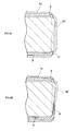
- Fig. 4 is a partly enlarged cross-sectional view of the punch cutter 6 which depicts a comparison between a case where the short-side cutting edge portion 61a of the punch cutter 6 is inclined and a case where short-side cutting edge portion 61a is not inclined.
- a boundary line 9' between the cut area and non-cut area of the short-side wall portion 13a is formed substantially along the thickness direction of the short-side wall portion 13a. In this case, most of the short-side wall portion 13a is cut away, with substantially no non-cut area remaining.
- the cut part 1b' of the removal portion 1b is significantly displaced from the product portion and significantly deformed near the boundary line 9' relative to the product portion, in accordance with the amount by which the punch cutter 6 cuts into the removal portion 1b (the amount of overlap with the die cutter 3).
- the boundary line 9 extends and inclines significantly in a circumferentially moving direction of the punch cutter 6 (a direction along the circumferential surface of the short-side wall portion 13a) relative to the thickness direction of the short-side wall portion 13a.
- the non-cut area is left in the short-side wall portion 13a over a range wider than the range in the case where the short-side cutting edge portion 61a is not inclined.
- the amount of overlap of the punch cutter 6 with the die cutter 3 is large in an area beyond the cut line 9.
- the cut portion 1b' is less significantly deformed relative to the product portion, and the deformation in the direction of the deformation relative to the product portion is also gentle along the cut line 9.
- connection portion When a larger part of the non-cut area is left in the short-side wall portion 13a as described above, the strength of the connection portion between the cut portion and the product portion can be increased. Furthermore, when such a connection portion is maintained until the final cutaway process for the removal portion 1b, stress concentration at the connection portion is relieved which is caused by uncontrollable movement of the cut portion 1b' of the removal portion 1b in connection with the movement of the punch cutter 6. This restrains the connection portion from being progressively split.
- the apparatus when the apparatus is configured such that the inclined short-side cutting edge portion 61a cuts substantially perpendicularly into the short-side wall portion 13a, that is, such that the short-side cutting edge portion 61a has a what is called shear angle, a cutting load associated with the initial cut is reduced, suppressing a possible split at the time of cutting.
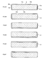
- Fig. 5 is a schematic diagram depicting a variation 1 of the above-described punch cutter 6.
- a punch cutter 61 is configured to have a shear angle not only on the short-side cutting edge portion 61a but also on a short-side cutting edge portion 61b1 and long-side cutting edge portions 62a1 and 62b1. That is, the short-side cutting edge portions and the long-side cutting edge portions are all configured to be nonparallel to the short-side wall portions and long-side wall portions of the intermediate 1. Thus, the cutting load can be reduced over approximately the entire circumference of the intermediate 1.
- the present invention is not limited to the above-described configurations, and the configuration may be any of various combinations of the parallel cutting edge portions and nonparallel cutting edge portions.
- Fig. 6 is a schematic diagram depicting a variation 2 of the punch cutter 6.
- a short-side cutting edge portion 61a2 is shaped like a triangle.
- the short-side cutting edge portion 61a2 initially cuts into the intermediate 1 to form two inclined boundary lines 92 in the intermediate 1.
- trimming can be achieved by advancing the punch cutter not only counterclockwise but also clockwise.
- the short-side cutting edge portion 61a2 is preferably shaped like an isosceles triangle as depicted in Fig. 6 . Vertices (angular corners) of the triangle may be appropriately dropped.
- the configurations of the short-side cutting edge portion 61b2 and the long-side cutting edge portions 62a2 and 62b2 are not particularly limited.
- Fig. 7 is a schematic diagram depicting a variation 3 of the punch cutter 6.
- a short-side cutting edge portion 61a3 is shaped like a convex curve.
- the short-side cutting edge portion 61a3 initially cuts into the short-side wall portion 13a to form two boundary lines 93 inclined line circular arcs, in the intermediate 1.
- trimming can be achieved by advancing the punch cutter not only counterclockwise but also clockwise.
- the convex curve shape of 61a3 may be a circular arc, an elliptic arc, a quadratic curve, or the like as depicted in Fig. 7 .
- the configurations of the short-side cutting edge portion 61b3 and long-side cutting edge portions 62a3 and 62b3 are not particularly limited.
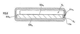
- Fig. 8 is a schematic diagram depicting a variation 4 of the punch cutter 6 and the usage of the variation 4.
- a punch cutter 64 is configured to be thinner than the punch cutter 6 according to Fig. 2 described above. That is, the configuration of long-side cutting edge portions 62a4 and 62b4 is similar to the corresponding configuration in the punch cutter 6 according to Fig. 2 , and short-side cutting edge portions 61a4 and 61b4 are also configured to have a small width. Then, when initially cutting into the short-side wall portion 13a of the intermediate 1, the punch cutter 64 is moved in a substantially oblique direction relative to the short-side wall portion 13a to form an inclined boundary line 94 in the intermediate 1.
- the apparatus trimming a rectangular container according to the present embodiment is an apparatus configured to trim the intermediate 1 by circumferentially moving the punch cutter.
- the apparatus 2 trimming a rectangular container substantially includes an upper frame 2a and a lower frame 2b.
- the upper frame 2a includes the die cutter 3 and a bottom pad 4.
- the lower frame 2b includes a mandrel 5, the punch cutter 6, the driving mechanism 7 that moves the punch cutter 6 relative to the mandrel 5, and an air vacuum hole 8 through which vacuumization is performed in order to insert the mandrel 5 into the product and through which air is fed in order to pull the mandrel 5 out from the product.
- the upper frame 2a and the lower frame 2b are configured to be able to move up and down to come into contact with and separate from each other.
- the above-described intermediate 1 is held by the upper frame 2a with the removal portion 1b down.
- the upper frame 2a and the lower frame 2b approach each other to place the intermediate 1 over the mandrel 5 of the lower frame 2b.
- Pins 40 are guided along an up-down stroke by a guide 41 provided on the frame of the upper frame 2a to press the bottom pad 4 against a lower surface of the bottom portion 11 of the intermediate 1 with a pressing force adjusted by an air cylinder 42.
- a vacuum hole 43 is formed in each of the pins 40 to allow the product (rectangular container 1a) to be drawn out from the mandrel 5 after trimming.
- the mandrel 5 includes a guide portion 5a that guides an inner peripheral surface of the intermediate 1 when the intermediate 1 is placed over the mandrel 5, and a support portion 5b that supports an area of an inner peripheral surface of the rectangular tubular portion 10 which lies on an inward side of the intermediate compared to the trim line (bottom portion 11 side).
- the support portion 5b is designed so as to form a predetermined clearance (for example, 0.1 mm) between the support portion 5b and the inner peripheral surface of the rectangular tubular portion 10.
- the clearance is designed to be as small as possible in order to prevent the intermediate 1 from being collapsed, damaged, or abnormally deformed.
- the boundary line between the lower surface and the upper surface is equal in height to the trim line on the intermediate 1.
- Well-known positioning pin structures are provided on the slidable surfaces of the mandrel 5 and the punch cutter 6.
- the mandrel 5 and the punch cutter 6 are automatically positioned relative to each other so as to return to the home position (origin) where the mandrel 5 and the punch cutter 6 overlap each other at substantially the same position in a plan view.
- pins 44 biased toward the slidable surface of the mandrel 5 by bias means such as a spring are provided in the slidable surface of the punch cutter 6.
- Dish-like recess portions having a sectional curvature greater than those of spherical head portions at the tips of the pins and having a larger diameter than the pins are formed in the slidable surface of the mandrel 5 at positions opposite to the tips of the pins 44 in the mandrel 5 located at the home position.
- the mandrel 5 and the punch cutter 6 move relative to each other so as to bring the pin tips into abutting contact with the deepest parts (central parts) of the recess portions by means of the bias force of the bias means.
- the center of the mandrel 5 aligns with the center of the punch cutter 6.
- the punch cutter 6 has the cutting edge portion 60 slightly projecting outward.
- the cutting edge portion 60 is provided all over the circumference of an edge of an outer peripheral surface of the punch cutter 6 which edge defines a boundary between the punch cutter 6 and the support portion 5b of the mandrel 5.
- the punch cutter 6 is moved in the horizontal direction (the direction along the trim line) relative to the mandrel 5 by means of the driving mechanism 7 described below to allow the removal portion 1b to be trimmed away from the intermediate 1.
- the driving mechanism 7 combines rotating motion and reciprocating motion to move the punch cutter 6 in the horizontal direction relative to the fixed die cutter 3 (upper frame 2a) and the mandrel 5.
- the driving mechanism 7 substantially includes an upper stand 71 that supports the mandrel 5 and the punch cutter 6, a lower stand 72 that supports the upper stand 71 so that the upper stand 71 is rotationally movable, a rotation mechanism 73 that rotationally moves the upper stand 71 relative to the lower stand 72, and a linear motion mechanism 74 that reciprocates the lower stand 72 in the horizontal direction.
- the rotation mechanism 73 includes gears 73a coupled to a servo motor 75 and a pair of eccentric pins 73b that is rotated by mechanical power transmitted via the gears 73a.
- the pair of eccentric pins 73b has gears 73c which mesh with the gears 73a and which have the same diameter and pitch as the diameter and pitch of the gears 73a.
- the upper stand 71 is rotationally movably supported by each pin of the pair of eccentric pins 73b.
- the upper stand 71 is supported at eccentric positions 73d that are in phase with the respective pins of the pair of eccentric pins 73b and thus moves rotationally without any change in angle (direction).
- the upper stand 71 is pressed in an up-down direction (vertical direction) relative to the lower stand 72 by means of presser portions 76 provided on the lower stand 72 while being allowed to move in the horizontal direction.
- the linear motion mechanism 74 is a linear motion mechanism that utilizes what is called s link mechanism (crank mechanism).
- the linear motion mechanism 74 includes a link portion 74b and a connection member 74c which convert axial rotating motion of an eccentric pin 74a (crank shaft) performed by a servo motor 77 into lateral reciprocating motion of the lower stand 72.
- the lower stand 72 is pressed by presser portions 78 provided on the frame (not depicted in the drawings) of the lower frame 2b, so as not to move in the up-down direction (vertical direction) relative to the frame, while the front-back moving direction (up-down direction in the figure) of the lower stand 72 is regulated.
- the driving mechanism 7 delicately controls the rotation angles of the gears 73a and eccentric pins 74a of the servo motors 75 and 77 to allow free control of the trajectory of the punch cutter in the X-Y horizontal direction. Furthermore, allowing the punch cutter to draw a curved trajectory enables an increase in speed. Moreover, varying the amount of eccentricity among the eccentric pins allows the travel distance of the punch cutter to be optionally varied.
- the driving mechanism 7 for the punch cutter 6 is provided on the lower frame 2b to move the mandrel 5 and the punch cutter 6 relative to each other.
- a driving mechanism for the die cutter 3 may be provided on the upper frame 2a so that the die cutter 3 moves to allow the mandrel 5 and the punch cutter 6 to move relative to each other.
- Fig. 12 is a plan view depicting another example of the lower frame of the apparatus trimming a rectangular container according to the present invention.
- a driving mechanism 7' is a combination of two linear motion mechanisms 74 described above. That is, the driving mechanism 7' substantially includes an upper stand 71' that supports the mandrel 5 and the punch cutter 6, a lower stand 72' that supports the upper stand 71', a linear motion mechanism 73' that reciprocates the upper stand 71' in the horizontal direction relative to the lower stand 72', and a linear motion mechanism 74' that reciprocates the lower stand 72' in the horizontal direction.
- the linear motion mechanism 73' is provided on the lower stand 72' to reciprocate the upper stand 71' in the lateral direction in the plan view in Fig. 12 relative to the lower stand 72'.
- the linear motion mechanism 74' reciprocates the lower stand 72' in the front-back direction (up-down direction in Fig. 4 ) in the plan view in Fig. 4 .
- the linear motion mechanism 73' is a linear motion mechanism that utilizes what is called s link mechanism.
- the linear motion mechanism 73' includes a link portion 73b' and a connection member 73c' which convert axial rotating motion of an eccentric pin 73a' performed by a servo motor 75' into lateral reciprocating motion of the upper stand 71'.
- the linear motion mechanism 74' is also a mechanism similar to the above-described linear motion mechanisms 74 and 73' , and includes a link portion 74b' and a connection member 74c' which convert axial rotating motion of an eccentric pin 74a' performed by a servo motor 77' into front-back reciprocating motion (up-down reciprocating motion in the plan view in Fig. 12 ) of the lower stand 72'. Furthermore, the upper stand 71' is pressed by presser portions 76' provided on the lower stand 72' so as not to move in the up-down direction (vertical direction) relative to the lower frame 72', while the front-back moving direction (up-down direction in the figure) of the upper stand 71' is regulated.
- the lower stand 72' is pressed by presser portions 78' provided on a frame (not shown in figures) of the lower frame 2b' so as not to move in the up-down direction (vertical direction) relative to the frame, while the lateral moving direction of the lower stand 72' is regulated.
- the driving mechanism 7' delicately controls the rotation angles of the gears 73a' and eccentric pins 74a' of the servo motors 75' and 77' to allow free control of the trajectory of the punch cutter in the X-Y horizontal direction.
- the description of the rectangular container involves the container with a substantially rectangular cross section.
- the container may have a square cross section or may have a cross-sectional shape similar to these cross sections.
Landscapes
- Engineering & Computer Science (AREA)
- Mechanical Engineering (AREA)
- Life Sciences & Earth Sciences (AREA)
- Forests & Forestry (AREA)
- Manufacturing & Machinery (AREA)
- Shaping Metal By Deep-Drawing, Or The Like (AREA)
- Punching Or Piercing (AREA)
- Perforating, Stamping-Out Or Severing By Means Other Than Cutting (AREA)
- Making Paper Articles (AREA)
Abstract
Description
- The present invention relates to a method for trimming a rectangular container and an apparatus trimming a rectangular container, and in particular, to a method for trimming a rectangular container with a rectangular cross section and an apparatus trimming such a rectangular container.
- A rectangular container shaped by drawing, drawing-ironing, or the like needs trimming, in a post-process, of an uneven edge of an opening in the rectangular container formed by these types of processing. Various trimming methods are known (
Patent Literature 1 to 3). - Besides the methods in
Patent Literature 1 to 3, a method for trimming a rectangular container is known in which short-side wall portions involving low cut loads are first removed (Fig. 13A ) and in which long-side wall portions involving high cut loads are then removed (Fig. 13B ), as depicted inFig. 13 . In such four-side cut trimming, a step is likely to be formed at the boundary between the short-side wall portion and the long-side wall portion on a trimmed end surface, as indicated by a dashed line inFig. 14 . Furthermore, the wall portions are cut by stroking a punch cutter on each side, and thus, at least four processes are needed. Moreover, a transfer press is used for cutting, and thus, a production rate is limited to 20 to 50 cpm (cans per minute: the number of cans produced per minute) in view of the life of a cam. - In view of a reduction in processes, a trimming apparatus is known by which a container is trimmed by circumferentially moving an inner-frame cutter (punch) as described in
Patent Literature 2 andPatent Literature 3. However, with such a trimming apparatus, a removal portion and a part of a product portion (remaining portion) remain connected together until the end of the process. Thus, for a rectangular container with a rectangular cross section as depicted inFig. 13 , the removal portion is likely to move uncontrollably as the cutter moves, imposing a heavy load on the boundary between the removal portion and the product portion. As a result, stress is concentrated at the boundary, which gradually begins to split. This leads to a crack or burr in the product. -
- [Patent Literature 1] Japanese Patent Application Laid-open No.
S49-45491 - [Patent Literature 2] Japanese Patent Application Laid-open No.
S44-8357 - [Patent Literature 3] Japanese Utility Model Application Laid-open No.
S59-85623 - An object of the present invention is to provide a method for trimming a rectangular container and an apparatus trimming a rectangular container for the purpose of enhancing machining precision when trimming a rectangular container.
- To accomplish the object, a method for trimming a rectangular container according to the present invention includes:
- when initially allowing a punch cutter to cut into a rectangular tubular portion of the untrimmed rectangular container, inclining the punch cutter relative to a thickness direction of a wall portion of the rectangular tubular portion at a trim line on the rectangular tubular portion; and
- then circumferentially moving the punch cutter along the trim line on the rectangular tubular portion to cut the rectangular tubular portion.
- The method for trimming a rectangular container according to the present invention may be configured as follows.
- 1. At least a cutting edge portion of the punch cutter which initially cuts into the rectangular tubular portion is nonparallel to the wall portion.
- 2. An entire circumference of a cutting edge portion of the punch cutter is nonparallel to the wall portion.
- 3. At least a cutting edge portion of the punch cutter which initially cuts into the rectangular tubular portion is triangular.
- 4. At least a cutting edge portion of the punch cutter which initially cuts into the rectangular tubular portion is shaped like a convex curve.
- 5. A cut made by the punch cutter in the inclined state is a cut made by moving the punch cutter in a direction of the inclination relative to the wall portion.
- 6. The rectangular container has a substantially rectangular cross section, and the punch cutter is initially allowed to cut into a short-side wall portion of the rectangular tubular portion.
- 7. A trajectory of circumferential movement of the punch cutter includes only a curved trajectory.
- Furthermore, to accomplish the object, an apparatus trimming a rectangular container according to the present invention includes:
- a die cutter that surrounds an outer periphery of a product portion of a rectangular tubular portion of the untrimmed rectangular container;
- a mandrel disposed inside the product portion to sandwich the product portion between the mandrel and the die cutter; and
- a punch cutter that circumferentially moves along a circumference of the rectangular tubular portion relative to the die cutter and the mandrel to cut away a removal portion of the rectangular tubular portion,
- in which, when the punch cutter is initially allowed to cut into the rectangular tubular portion of the untrimmed rectangular container, the punch cutter is inclined relative to a thickness direction of a wall portion of the rectangular tubular portion at a trim line on the rectangular tubular portion; and
- then the punch cutter is circumferentially moved along the trim line on the rectangular tubular portion to cut the rectangular tubular portion.
- The apparatus trimming the rectangular container according to the present invention may be configured as follows.
- 1. At least a cutting edge portion of the punch cutter which initially cuts into the rectangular tubular portion is nonparallel to the wall portion.
- 2. An entire circumference of a cutting edge portion of the punch cutter is nonparallel to the wall portion.
- 3. At least a cutting edge portion of the punch cutter which initially cuts into the rectangular tubular portion is triangular.
- 4. At least a cutting edge portion of the punch cutter which initially cuts into the rectangular tubular portion is shaped like a convex curve.
- 5. The punch cutter is moved in a direction of the inclination relative to the wall portion.
- 6. The rectangular container has a substantially rectangular cross section, and the punch cutter is initially allowed to cut into a short-side wall portion of the rectangular tubular portion.
- 7. A trajectory of circumferential movement of the punch cutter includes only a curved trajectory.
- According to the present invention, the punch cutter is inclined relative to the thickness direction of the rectangular tubular portion when cutting into the rectangular tubular portion. Thus, a large connection portion can be left which keeps the removal portion and the product portion connected together until the end of the process. This enables the strength of the connection portion to be improved. Thus, the connection portion is restrained from being progressively split while the punch cutter is circumferentially moving, allowing suppression of a possible crack or bur in a product. Therefore, a preferable cut surface with no step can be obtained.
- Furthermore, the present invention uses, for cutting, the punch cutter with the cutting edge portion nonparallel to at least the wall portion of the rectangular tubular portion into which is initially cut. Thus, a possible crack can be suppressed at the time of the initial cut. Furthermore, the inclination angle of a boundary line defined by the initial cut can be easily adjusted by the angle of the cutting edge portion to the wall portion.
- Additionally, according to the present invention, the punch cutter is initially allowed to cut into the short-side wall portion of the rectangular tubular portion with the rectangular cross section, the short-side wall portion being more rigid than a long-side wall portion. Thus, a possible crack can be suppressed at the time of the initial cut.
- In addition, according to the present invention, the trajectory of circumferential movement of the punch cutter includes only a curved trajectory. Thus, the movement of the punch cutter can be made faster.
-
-
Fig. 1 is a perspective view depicting a configuration of a rectangular container manufactured using a method for trimming a rectangular container and an apparatus trimming a rectangular container according to the present invention, withFig. 1A being a perspective view depicting an untrimmed state of a rectangular container intermediate, andFig. 1B being a perspective view depicting a trimmed state of the rectangular container intermediate. -
Fig. 2 is a schematic diagram depicting a configuration of a punch cutter used for the method for trimming a rectangular container according to the present invention, withFig. 2A being a schematic diagram of the punch cutter and a surface, which is to be cut off, of the rectangular container intermediate, and withFig. 2B being a schematic diagram depicting a movement path of the center of gravity of the punch cutter. -
Fig. 3 is a schematic diagram illustrating a positional relation between the punch cutter and the surface, which is to be cut off, of the rectangular container intermediate which is observed when the punch cutter follows a path C1 to C5 depicted inFig. 2A . -
Fig. 4 is a partly enlarged cross-sectional view of a short-side cutting edge portion of the punch cutter, in whichFig. 4A is a cross-sectional view depicting a case where the short-side cutting edge portion is not inclined, andFig. 4B is a cross-sectional view depicting a case where the short-side cutting edge portion is inclined. -
Fig. 5 is a schematic diagram depicting avariation 1 of the punch cutter. -
Fig. 6 is a schematic diagram depicting avariation 2 of the punch cutter. -
Fig. 7 is a schematic diagram depicting avariation 3 of the punch cutter. -
Fig. 8 is a schematic diagram depicting avariation 4 of the punch cutter. -
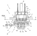
Fig. 9 is a schematic cross-sectional view of an apparatus trimming a rectangular container according to the present invention as seen from the front. -
Fig. 10 is an enlarged cross-sectional view of the vicinity of a trim line made by the apparatus trimming a rectangular container according to the present invention. -
Fig. 11 is a plan view of a lower frame of the apparatus trimming a rectangular container according to the present invention. -
Fig. 12 is a plan view depicting another example of a lower frame. -
Fig. 13 is a perspective view depicting conventional four-cut trimming, in whichFig. 13A depicts a state where short-side wall portions have been cut, andFig. 13B depicts a state where long-side wall portions have subsequently been cut. -
Fig. 14 is a schematic diagram depicting a cut surface resulting from conventional four-side cutting. - An embodiment for carrying out the present invention will be described with reference to the drawings.
- The materials, shapes, relative dispositions, and the like of components of the present embodiment may be appropriately changed and are not intended to limit the scope of the present invention to the present embodiment described below.
- As depicted in
Fig. 1 , arectangular container 1a is manufactured (a product shape is applied to therectangular container 1a) by trimming (cutting) aremoval portion 1b away from an intermediate 1. - As depicted in
Fig. 1B , therectangular container 1a has a structure shaped like a bottomed cylinder and in which a rectangulartubular portion 10 and abottom portion 11 are integrally molded. The rectangulartubular portion 10 has a substantially rectangular cross section and includes a substantially rectangular openingend surface 12, a pair of short-side wall portions 13 that forms short sides with a substantially rectangular cross section, and a pair of long-side wall portions 14 that forms long sides with a substantially rectangular cross section. - As depicted in
Fig. 1A , the intermediate 1 includes thebottom portion 11, the short-side wall portions 13, and the long-side wall portions 14 and is molded to have theremoval portion 1b as depicted inFig. 1B . A method for manufacturing the intermediate 1 is not particularly limited but the intermediate 1 may be molded using well-known drawing (deep drawing) or drawing-ironing or impact molding. Thus, a specific description of a machining method is omitted. An opening end of the intermediate 1 opposite to thebottom portion 11 has an irregular shape because the well-known machining has difficulty forming an even edge (height) of the opening end. Theremoval portion 1b, which is the irregular shape portion, is trimmed along a trim line TL to form the openingend surface 12 on the rectangulartubular portion 10. Thus, the final product shape of therectangular container 1a is obtained. - The
rectangular container 1a is manufactured from, for example, pure aluminum, or an aluminum alloy, or a metal plate such as an SPCE (cold rolled steel plate), an SUS (stainless steel), or an iron nickel steel plate. In an application of therectangular container 1a, for example, therectangular container 1a can be used as an outer can for a rectangular battery by housing various power generation elements (for example, electrodes, separators, and the like) providing a battery in therectangular container 1a, and sealing the opening with a cap (not depicted in the drawings). - An embodiment of the method for trimming a rectangular container according to the present invention will be described with reference to
Figs. 2 to 8 . - The trimming method involves, as disclosed in
Patent Literature - The outer peripheral shape of a
cutting edge portion 60 of apunch cutter 6 used for the method for trimming a rectangular container according to the present invention substantially conforms to the inner peripheral shape of the rectangulartubular portion 10 of the intermediate 1. That is, thecutting edge portion 60 includes short-sidecutting edge portions side wall portions tubular portion 10 and long-sidecutting edge portions side wall portions cutting edge portions cutting edge portions cutting edge portion 60 in an annular shape (not illustrated in detail in the figure) (thecutting edge portion 60 will be described below usingFig. 10 ). - In the
punch cutter 6 according to the present embodiment, the short-sidecutting edge portion 61a of thecutting edge portion 60 which is opposite to the short-side wall portion 13a is configured to be nonparallel to the short-side wall portion 13a. The other cutting edge portions are configured to be parallel to the opposite wall portions. - Arrows C1 to C6 depicted in
Fig. 2A indicate a path (trajectory) along which the center of gravity of thepunch cutter 6 moves when thepunch cutter 6 moves. (InFig. 2A , the sizes of the arrows are depicted to be larger than the actual amounts of movement in order to make the movement direction of the center of gravity of thepunch cutter 6 easily understood). Furthermore, relay points P0 to P5 between the arrows C1 to C6 are points passed by the center of gravity of thepunch cutter 6. In the present embodiment, P2 to P4 denote points through which the center of gravity of thepunch cutter 6 passes in order to obtain an amount of cutting that allows thepunch cutter 6 to reliably cut thewall portions punch cutter 6 moves to P2, the long-sidecutting edge portion 62a of thepunch cutter 6 is positioned at an outer edge of the rectangular container long-side wall portion 14a. - A coarsely dashed arrow SC in
Fig. 2 (B) depicts a shortcut path. The shortcut path SC is formed only of a curved path in order to allow thepunch cutter 6 to take a shortcut without passing the first relay point P1 and to pass each of the relay points P0 and P2 to P5. The first relay point P1 need not be reached when the vicinity of the relay point P1 is passed as long as formation of an oblique boundary line described below is ensured due to initial cut. Thus, the movement distance from the home position P0 to the relay point P2 can be shortened. - When the
punch cutter 6 follows a curved path like the shortcut path SC inFig. 2(B) , the amount of overlap (see a dimension L inFig. 10 ) of thepunch cutter 6 with thedie cutter 3 increases by a value equal to the amount by which the distance of the center of gravity from the relay point P0 is displaced outward from the line of arrows C3 to C5. Thus, a part of theremoval portion 1b cut away from the product portion of the intermediate 1 is likely to move uncontrollably as thepunch cutter 6 moves. Consequently, a load is likely to be imposed on the boundary between theremoval portion 1b and the product portion (rectangular container 1a) of the intermediate 1. Therefore, to restrain the boundary portion from being progressively split as a result of stress concentration, the degree of curvature of the movement path of thepunch cutter 6, that is, the degree by which the linear trajectory C1 to C6 inFigs. 2A and 2B can be brought closer to a curved trajectory like the shortcut path SC depicted inFig. 2B , is appropriately set in accordance with product specifications or the like. - As described above, the movement path of the
punch cutter 6 is formed only of the curved paths to eliminate or reduce rapid turnarounds, allowing thepunch cutter 6 to be driven faster. When the movement path of thepunch cutter 6 is formed only of linear paths, for example, when thepunch cutter 6 is turned around through 90 degrees at a high speed, the apparatus may be, for example, damaged by an impact. Furthermore, in connection with the inertia mass of a driven point on the apparatus, when a sudden stop is followed by an abrupt acceleration with the direction changed, the acceleration and deceleration are limited. On the other hand, when thepunch cutter 6 is moved along a curved path, the acceleration and deceleration can be naturally and efficiently achieved simultaneously in both X and Y directions. For example, the direction can be freely changed by accelerating moderately in the Y direction while decelerating moderately in the X direction. Therefore, movement along the curved trajectory needs to go a slightly longer way around than movement along the linear trajectory but avoids imposing a mechanical load on adriving mechanism 7 and enables a faster operation. The path may be a combination of the linear trajectory and the curved trajectory. That is, if a path with no sudden turnaround is formed for thepunch cutter 6, the path may be an appropriate combination of the linear trajectory and the curved trajectory. -
Fig. 3 is a schematic diagram depicting a positional relation between thepunch cutter 6 and the intermediate 1 which is observed when thepunch cutter 6 follows the path C1 to C5 depicted inFig. 2A .Fig. 3 assumes that the external shape of the rectangulartubular portion 10 of the intermediate 1 is substantially the same as the shape of an inner peripheral surface of thedie cutter 3, with no clearance between the rectangulartubular portion 10 and thedie cutter 3. In actuality, a design clearance is provided. -
Fig. 3A depicts a positional relation between thepunch cutter 6 and the intermediate 1 which is observed when the center of gravity of thepunch cutter 6 lies at the home position P0. That is,Fig. 3A depicts a state where the intermediate 1 is set at a predetermined position for trimming. -
Fig. 3B depicts a positional relation between thepunch cutter 6 and the intermediate 1 which is observed when the center of gravity of thepunch cutter 6 lies at the relay point P1. That is,Fig. 3B depicts a state where the center of gravity of thepunch cutter 6 has followed the path C1 inFig. 2A from the home position P0 to move rightward and reached the relay point P1. This movement causes the short-sidecutting edge portion 61a to cut into the short-side wall portion 13a. The short-sidecutting edge portion 61a is inclined relative to the short-side wall portion 13a, thepunch cutter 6 is inclined, during cutting, relative to the thickness direction of the short-side wall portion 13a on the trim line. Furthermore, the short-sidecutting edge portion 61a is not allowed to penetrate the short-side wall portion 13a, and thus, a cut formed in the short-side wall portion 13a is substantially chevron-shaped in a cross section along the trim line. That is, in a cross section along the trim line, one boundary line (cut line) between a cut area and a non-cut area of the short-side wall portion 13a defined by the short-sidecutting edge portion 61a is aboundary line 9 extending in a direction inclined relative to the thickness direction of the short-side wall portion 13a. In a trimming process with thepunch cutter 6 according to the present embodiment, theboundary line 9 is left until a final cutting process where theremoval portion 1b is completely cut away from the product portion of the intermediate 1. -
Fig. 3C depicts a positional relation between thepunch cutter 6 and the intermediate 1 which is observed when the center of gravity of thepunch cutter 6 lies at the relay point P2. That is,Fig. 3C depicts a state where the center of gravity of thepunch cutter 6 has followed the path C2 inFig. 2A from the relay point P1 to move inward and reached the relay point P2. This movement cuts away most of the long-side wall portion 14a and the connection portion between the long-side wall portion 14a and the short-side wall portion 13a. That is, the cut end defined by the initial cut made by thepunch cutter 6 is extended over most of the entire area of the long-side wall portion 14a with theboundary line 9 left (the other boundary line moves to the vicinity of the short-side wall portion 13b). -
Fig. 3D depicts a positional relation between thepunch cutter 6 and the intermediate 1 which is observed when the center of gravity of thepunch cutter 6 lies at the relay point P3. That is,Fig. 3D depicts a state where the center of gravity of thepunch cutter 6 follows the path C3 inFig. 2A from the relay point P2 to move leftward and reached the relay point P3. This movement cuts away the remaining part of the long-side wall portion 14a, the connection portion between the long-side wall portion 14a and the short-side wall portion 13b, and most of the short-side wall portion 13b. That is, the cut end defined by the initial cut made by thepunch cutter 6 is further extended over most of the entire area of the short-side wall portion 13b with theboundary line 9 left (the other boundary line moves to the vicinity of the long-side wall portion 14b). -
Fig. 3E depicts a positional relation between thepunch cutter 6 and the intermediate 1 which is observed when the center of gravity of thepunch cutter 6 lies at the relay point P4. That is,Fig. 3E depicts a state where the center of gravity of thepunch cutter 6 follows the path C4 inFig. 2A from the relay point P3 to move forward and reached the relay point P5. This movement cuts away the remaining part of the short-side wall portion 13b, the connection portion between the short-side wall portion 13b and the long-side wall portion 14b, and most of the long-side wall portion 14b. That is, the cut end defined by the initial cut made by thepunch cutter 6 is further extended over most of the entire area of the long-side wall portion 14b with theboundary line 9 left (the other boundary line moves to the vicinity of the short-side wall portion 13a). At this point in time, the connection portion remaining between theremoval portion 1b and the product portion (rectangular container 1a) of the intermediate 1 is the small remaining part of the long-side wall portion 14b, the connection portion between the long-side wall portion 14b and the short-side wall portion 13a, and the connection area of the short-side wall portion 13a left across theboundary line 9. -
Fig. 3F depicts a positional relation between thepunch cutter 6 and the intermediate 1 which is observed when the center of gravity of thepunch cutter 6 lies at the relay point P5. That is,Fig. 3F depicts a state where the center of gravity of thepunch cutter 6 follows the path C5 inFig. 2A from the relay point P4 to move rightward and reached the cutting end point P5. This state corresponds to a final cutting process where thepunch cutter 6 completely cuts theremoval portion 1b away from the product portion (rectangular container 1a) of the intermediate 1. InFig. 3F , thepunch cutter 6 moves to a position immediately before a position where thepunch cutter 6 cuts completely through the connection portion between the long-side wall portion 14b and the short-side wall portion 13a to cut away the part of theremoval portion 1b which remains at the end by means of the impact of the movement. However, thepunch cutter 6 may be allowed to cut completely through the connection portion to cut away theremoval portion 1b depending on conditions such as the material and the punch cutter. When the final cutting ends, thepunch cutter 6 follows the path C6 inFig. 2A from the cutting end point P5 to return to the home position P0. - In the present embodiment, the
punch cutter 6 moves relative to the intermediate 1 with the angle of thepunch cutter 6 unchanged, and thus, the inclination angle of the short-sidecutting edge portion 61a remains equal to the inclination angle of theboundary line 9 throughout the trimming process. Thus, in the final cutting process, the short-sidecutting edge portion 61a of thepunch cutter 6 overlaps theboundary line 9 in the middle of movement. The cut end defined on the short-side wall portion 13a by the initial cut is also spread in a direction opposite to the above-described direction by the short-sidecutting edge portion 61a (and also the curved cutting edge portion between the short-sidecutting edge portion 61a and the long-sidecutting edge portion 62a depending on the path) to cut away all of the remaining connection portion. -
Fig. 4 is a partly enlarged cross-sectional view of thepunch cutter 6 which depicts a comparison between a case where the short-sidecutting edge portion 61a of thepunch cutter 6 is inclined and a case where short-sidecutting edge portion 61a is not inclined. As depicted inFig. 4A , when the short-sidecutting edge portion 61a is not inclined, a boundary line 9' between the cut area and non-cut area of the short-side wall portion 13a is formed substantially along the thickness direction of the short-side wall portion 13a. In this case, most of the short-side wall portion 13a is cut away, with substantially no non-cut area remaining. Furthermore, thecut part 1b' of theremoval portion 1b is significantly displaced from the product portion and significantly deformed near the boundary line 9' relative to the product portion, in accordance with the amount by which thepunch cutter 6 cuts into theremoval portion 1b (the amount of overlap with the die cutter 3). - On the other hand, as depicted in
Fig. 4B , when the short-sidecutting edge portion 61a is inclined, theboundary line 9 extends and inclines significantly in a circumferentially moving direction of the punch cutter 6 (a direction along the circumferential surface of the short-side wall portion 13a) relative to the thickness direction of the short-side wall portion 13a. In this case, the non-cut area is left in the short-side wall portion 13a over a range wider than the range in the case where the short-sidecutting edge portion 61a is not inclined. Furthermore, the amount of overlap of thepunch cutter 6 with thedie cutter 3 is large in an area beyond thecut line 9. Thus, thecut portion 1b' is less significantly deformed relative to the product portion, and the deformation in the direction of the deformation relative to the product portion is also gentle along thecut line 9. - When a larger part of the non-cut area is left in the short-
side wall portion 13a as described above, the strength of the connection portion between the cut portion and the product portion can be increased. Furthermore, when such a connection portion is maintained until the final cutaway process for theremoval portion 1b, stress concentration at the connection portion is relieved which is caused by uncontrollable movement of thecut portion 1b' of theremoval portion 1b in connection with the movement of thepunch cutter 6. This restrains the connection portion from being progressively split. - Moreover, when the apparatus is configured such that the inclined short-side
cutting edge portion 61a cuts substantially perpendicularly into the short-side wall portion 13a, that is, such that the short-sidecutting edge portion 61a has a what is called shear angle, a cutting load associated with the initial cut is reduced, suppressing a possible split at the time of cutting. -
Fig. 5 is a schematic diagram depicting avariation 1 of the above-describedpunch cutter 6. Apunch cutter 61 is configured to have a shear angle not only on the short-sidecutting edge portion 61a but also on a short-side cutting edge portion 61b1 and long-side cutting edge portions 62a1 and 62b1. That is, the short-side cutting edge portions and the long-side cutting edge portions are all configured to be nonparallel to the short-side wall portions and long-side wall portions of the intermediate 1. Thus, the cutting load can be reduced over approximately the entire circumference of the intermediate 1. The present invention is not limited to the above-described configurations, and the configuration may be any of various combinations of the parallel cutting edge portions and nonparallel cutting edge portions. - Furthermore,
Fig. 6 is a schematic diagram depicting avariation 2 of thepunch cutter 6. In apunch cutter 62, a short-side cutting edge portion 61a2 is shaped like a triangle. The short-side cutting edge portion 61a2 initially cuts into the intermediate 1 to form twoinclined boundary lines 92 in the intermediate 1. Thus, trimming can be achieved by advancing the punch cutter not only counterclockwise but also clockwise. Additionally, the short-side cutting edge portion 61a2 is preferably shaped like an isosceles triangle as depicted inFig. 6 . Vertices (angular corners) of the triangle may be appropriately dropped. The configurations of the short-side cutting edge portion 61b2 and the long-side cutting edge portions 62a2 and 62b2 are not particularly limited. - Additionally,
Fig. 7 is a schematic diagram depicting avariation 3 of thepunch cutter 6. In a punch cutter 63, a short-side cutting edge portion 61a3 is shaped like a convex curve. The short-side cutting edge portion 61a3 initially cuts into the short-side wall portion 13a to form two boundary lines 93 inclined line circular arcs, in the intermediate 1. Thus, trimming can be achieved by advancing the punch cutter not only counterclockwise but also clockwise. The convex curve shape of 61a3 may be a circular arc, an elliptic arc, a quadratic curve, or the like as depicted inFig. 7 . The configurations of the short-side cutting edge portion 61b3 and long-side cutting edge portions 62a3 and 62b3 are not particularly limited. - Moreover,
Fig. 8 is a schematic diagram depicting avariation 4 of thepunch cutter 6 and the usage of thevariation 4. Apunch cutter 64 is configured to be thinner than thepunch cutter 6 according toFig. 2 described above. That is, the configuration of long-side cutting edge portions 62a4 and 62b4 is similar to the corresponding configuration in thepunch cutter 6 according toFig. 2 , and short-side cutting edge portions 61a4 and 61b4 are also configured to have a small width. Then, when initially cutting into the short-side wall portion 13a of the intermediate 1, thepunch cutter 64 is moved in a substantially oblique direction relative to the short-side wall portion 13a to form aninclined boundary line 94 in the intermediate 1. - Now, an embodiment of an apparatus trimming a rectangular container according to the present invention will be described with reference to
Figs 9 to 12 . The apparatus trimming a rectangular container according to the present embodiment is an apparatus configured to trim the intermediate 1 by circumferentially moving the punch cutter. - As depicted in
Fig. 9 , theapparatus 2 trimming a rectangular container according to the present invention substantially includes anupper frame 2a and alower frame 2b. Theupper frame 2a includes thedie cutter 3 and abottom pad 4. Thelower frame 2b includes amandrel 5, thepunch cutter 6, thedriving mechanism 7 that moves thepunch cutter 6 relative to themandrel 5, and anair vacuum hole 8 through which vacuumization is performed in order to insert themandrel 5 into the product and through which air is fed in order to pull themandrel 5 out from the product. - The
upper frame 2a and thelower frame 2b are configured to be able to move up and down to come into contact with and separate from each other. The above-described intermediate 1 is held by theupper frame 2a with theremoval portion 1b down. Theupper frame 2a and thelower frame 2b approach each other to place the intermediate 1 over themandrel 5 of thelower frame 2b. -
Pins 40 are guided along an up-down stroke by aguide 41 provided on the frame of theupper frame 2a to press thebottom pad 4 against a lower surface of thebottom portion 11 of the intermediate 1 with a pressing force adjusted by anair cylinder 42. Thus, the intermediate 1 is prevented from being displaced upward or downward during trimming. Furthermore, avacuum hole 43 is formed in each of thepins 40 to allow the product (rectangular container 1a) to be drawn out from themandrel 5 after trimming. - The
mandrel 5 includes aguide portion 5a that guides an inner peripheral surface of the intermediate 1 when the intermediate 1 is placed over themandrel 5, and asupport portion 5b that supports an area of an inner peripheral surface of the rectangulartubular portion 10 which lies on an inward side of the intermediate compared to the trim line (bottom portion 11 side). Thesupport portion 5b is designed so as to form a predetermined clearance (for example, 0.1 mm) between thesupport portion 5b and the inner peripheral surface of the rectangulartubular portion 10. However, the clearance is designed to be as small as possible in order to prevent the intermediate 1 from being collapsed, damaged, or abnormally deformed. - A lower surface of the
support portion 5b of themandrel 5 and an upper surface of thepunch cutter 6 slidably abut against each other. The boundary line between the lower surface and the upper surface is equal in height to the trim line on the intermediate 1. When thepunch cutter 6 is moved in a horizontal direction by thedriving mechanism 7 described below, movement of themandrel 5 is regulated by thedie cutter 3 via the intermediate 1. - Well-known positioning pin structures are provided on the slidable surfaces of the
mandrel 5 and thepunch cutter 6. When the movement restriction imposed on themandrel 5 by thedie cutter 3 is lifted, themandrel 5 and thepunch cutter 6 are automatically positioned relative to each other so as to return to the home position (origin) where themandrel 5 and thepunch cutter 6 overlap each other at substantially the same position in a plan view. In the present embodiment, pins 44 biased toward the slidable surface of themandrel 5 by bias means such as a spring are provided in the slidable surface of thepunch cutter 6. Dish-like recess portions having a sectional curvature greater than those of spherical head portions at the tips of the pins and having a larger diameter than the pins are formed in the slidable surface of themandrel 5 at positions opposite to the tips of thepins 44 in themandrel 5 located at the home position. When no external force is applied in the horizontal direction, themandrel 5 and thepunch cutter 6 move relative to each other so as to bring the pin tips into abutting contact with the deepest parts (central parts) of the recess portions by means of the bias force of the bias means. Thus, the center of themandrel 5 aligns with the center of thepunch cutter 6. This configuration is only an example, and another conventional technique may be appropriately applicable. - As depicted in
Fig. 10 , thepunch cutter 6 has thecutting edge portion 60 slightly projecting outward. Thecutting edge portion 60 is provided all over the circumference of an edge of an outer peripheral surface of thepunch cutter 6 which edge defines a boundary between thepunch cutter 6 and thesupport portion 5b of themandrel 5. Thepunch cutter 6 is moved in the horizontal direction (the direction along the trim line) relative to themandrel 5 by means of thedriving mechanism 7 described below to allow theremoval portion 1b to be trimmed away from the intermediate 1. - As depicted in
Fig. 9 andFig. 11 , thedriving mechanism 7 combines rotating motion and reciprocating motion to move thepunch cutter 6 in the horizontal direction relative to the fixed die cutter 3 (upper frame 2a) and themandrel 5. Thedriving mechanism 7 substantially includes anupper stand 71 that supports themandrel 5 and thepunch cutter 6, alower stand 72 that supports theupper stand 71 so that theupper stand 71 is rotationally movable, arotation mechanism 73 that rotationally moves theupper stand 71 relative to thelower stand 72, and alinear motion mechanism 74 that reciprocates thelower stand 72 in the horizontal direction. - The
rotation mechanism 73 includesgears 73a coupled to aservo motor 75 and a pair ofeccentric pins 73b that is rotated by mechanical power transmitted via thegears 73a. The pair ofeccentric pins 73b hasgears 73c which mesh with thegears 73a and which have the same diameter and pitch as the diameter and pitch of thegears 73a. Theupper stand 71 is rotationally movably supported by each pin of the pair ofeccentric pins 73b. Theupper stand 71 is supported ateccentric positions 73d that are in phase with the respective pins of the pair ofeccentric pins 73b and thus moves rotationally without any change in angle (direction). Furthermore, theupper stand 71 is pressed in an up-down direction (vertical direction) relative to thelower stand 72 by means ofpresser portions 76 provided on thelower stand 72 while being allowed to move in the horizontal direction. - The
linear motion mechanism 74 is a linear motion mechanism that utilizes what is called s link mechanism (crank mechanism). Thelinear motion mechanism 74 includes alink portion 74b and aconnection member 74c which convert axial rotating motion of aneccentric pin 74a (crank shaft) performed by aservo motor 77 into lateral reciprocating motion of thelower stand 72. Thelower stand 72 is pressed bypresser portions 78 provided on the frame (not depicted in the drawings) of thelower frame 2b, so as not to move in the up-down direction (vertical direction) relative to the frame, while the front-back moving direction (up-down direction in the figure) of thelower stand 72 is regulated. - The
driving mechanism 7 delicately controls the rotation angles of thegears 73a andeccentric pins 74a of theservo motors driving mechanism 7 for thepunch cutter 6 is provided on thelower frame 2b to move themandrel 5 and thepunch cutter 6 relative to each other. However, a driving mechanism for thedie cutter 3 may be provided on theupper frame 2a so that thedie cutter 3 moves to allow themandrel 5 and thepunch cutter 6 to move relative to each other. -
Fig. 12 is a plan view depicting another example of the lower frame of the apparatus trimming a rectangular container according to the present invention. A driving mechanism 7' is a combination of twolinear motion mechanisms 74 described above. That is, the driving mechanism 7' substantially includes an upper stand 71' that supports themandrel 5 and thepunch cutter 6, a lower stand 72' that supports the upper stand 71', a linear motion mechanism 73' that reciprocates the upper stand 71' in the horizontal direction relative to the lower stand 72', and a linear motion mechanism 74' that reciprocates the lower stand 72' in the horizontal direction. The linear motion mechanism 73' is provided on the lower stand 72' to reciprocate the upper stand 71' in the lateral direction in the plan view inFig. 12 relative to the lower stand 72'. On the other hand, the linear motion mechanism 74' reciprocates the lower stand 72' in the front-back direction (up-down direction inFig. 4 ) in the plan view inFig. 4 . - Like the above-described
linear motion mechanism 74, the linear motion mechanism 73' is a linear motion mechanism that utilizes what is called s link mechanism. The linear motion mechanism 73' includes alink portion 73b' and aconnection member 73c' which convert axial rotating motion of aneccentric pin 73a' performed by a servo motor 75' into lateral reciprocating motion of the upper stand 71'. The linear motion mechanism 74' is also a mechanism similar to the above-describedlinear motion mechanisms 74 and 73' , and includes alink portion 74b' and aconnection member 74c' which convert axial rotating motion of aneccentric pin 74a' performed by a servo motor 77' into front-back reciprocating motion (up-down reciprocating motion in the plan view inFig. 12 ) of the lower stand 72'. Furthermore, the upper stand 71' is pressed by presser portions 76' provided on the lower stand 72' so as not to move in the up-down direction (vertical direction) relative to the lower frame 72', while the front-back moving direction (up-down direction in the figure) of the upper stand 71' is regulated. Additionally, the lower stand 72' is pressed by presser portions 78' provided on a frame (not shown in figures) of thelower frame 2b' so as not to move in the up-down direction (vertical direction) relative to the frame, while the lateral moving direction of the lower stand 72' is regulated. - Like the
driving mechanism 7, the driving mechanism 7' delicately controls the rotation angles of thegears 73a' andeccentric pins 74a' of the servo motors 75' and 77' to allow free control of the trajectory of the punch cutter in the X-Y horizontal direction. - In the present invention, the description of the rectangular container involves the container with a substantially rectangular cross section. However, the container may have a square cross section or may have a cross-sectional shape similar to these cross sections.
-
- 1
- Intermediate of rectangular container
- 1a
- Rectangular container (product)
- 1b
- Removal portion
- 10
- Rectangular tubular portion
- 11
- Bottom portion
- 12
- Opening end surface
- 13
- Short-side wall portion
- 14
- Long-side wall portion
- 2
- Rectangular-container trimmer
- 2a
- Upper frame
- 2b
- Lower frame
- 3
- Die cutter
- 4
- Bottom pad
- 5
- Mandrel
- 6
- Punch cutter
- 60
- Cutting edge portion
- 61
- Short-side cutting edge portion
- 62
- Long-side cutting edge portion
- 7
- Driving mechanism
- 8
- Air vacuum hole
- 9
- Boundary line
Claims (16)
- A method for trimming a rectangular container,
the method comprising:when initially allowing a punch cutter to cut into a rectangular tubular portion of the untrimmed rectangular container, inclining the punch cutter relative to a thickness direction of a wall portion of the rectangular tubular portion at a trim line on the rectangular tubular portion; andthen circumferentially moving the punch cutter along the trim line on the rectangular tubular portion to cut the rectangular tubular portion. - The method for trimming a rectangular container according to claim 1, wherein at least a cutting edge portion of the punch cutter which initially cuts into the rectangular tubular portion is nonparallel to the wall portion.
- The method for trimming a rectangular container according to claim 1, wherein an entire circumference of the cutting edge portion of the punch cutter is nonparallel to the wall portion.
- The method for trimming a rectangular container according to claim 1, wherein a least the cutting edge portion of the punch cutter which initially cuts into the rectangular tubular portion is triangular.
- The method for trimming a rectangular container according to claim 1, wherein at least the cutting edge portion of the punch cutter which initially cuts into the rectangular tubular portion is shaped like a convex curve.
- The method for trimming a rectangular container according to claim 1, wherein a cut made by the punch cutter in the inclined state is a cut made by moving the punch cutter in a direction of the inclination relative to the wall portion.
- The method for trimming a rectangular container according to any one of claims 1 to 6, wherein the rectangular container has a substantially rectangular cross section, and the punch cutter is initially allowed to cut into a short-side wall portion of the rectangular tubular portion.
- The method for trimming a rectangular container according to any one of claims 1 to 7, wherein a trajectory of circumferential movement of the punch cutter comprises only a curved trajectory.
- An apparatus trimming a rectangular container,
the apparatus comprising:a die cutter that surrounds an outer periphery of a product portion of a rectangular tubular portion of the untrimmed rectangular container;a mandrel that is disposed inside the product portion to sandwich the product portion between the mandrel and the die cutter; anda punch cutter that circumferentially moves along a circumference of the rectangular tubular portion relative to the die cutter and the mandrel to cut away a removal portion of the rectangular tubular portion, whereinwhen the punch cutter is initially allowed to cut into the rectangular tubular portion of the untrimmed rectangular container, the punch cutter is inclined relative to a thickness direction of a wall portion of the rectangular tubular portion at a trim line on the rectangular tubular portion; andthen the punch cutter is circumferentially moved along the trim line on the rectangular tubular portion to cut the rectangular tubular portion. - The apparatus trimming a rectangular container according to claim 9, wherein at least a cutting edge portion of the punch cutter which initially cuts into the rectangular tubular portion is nonparallel to the wall portion.
- The apparatus trimming a rectangular container according to claim 9, wherein an entire circumference of a cutting edge portion of the punch cutter is nonparallel to the wall portion.
- The apparatus trimming a rectangular container according to claim 9, wherein a least the cutting edge portion of the punch cutter which initially cuts into the rectangular tubular portion is triangular.
- The apparatus trimming a rectangular container according to claim 9, wherein at least a cutting edge portion of the punch cutter which initially cuts into the rectangular tubular portion is shaped like a convex curve.
- The apparatus trimming a rectangular container according to claim 9, wherein the punch cutter is moved in a direction of the inclination relative to the wall portion.
- The apparatus trimming a rectangular container according to any one of claims 9 to 14, wherein the rectangular container has a substantially rectangular cross section, and the punch cutter is initially allowed to cut into a short-side wall portion of the rectangular tubular portion.
- The apparatus trimming a rectangular container according to any one of claims 9 to 15, wherein a trajectory of circumferential movement of the punch cutter comprises only a curved trajectory.
Applications Claiming Priority (2)
| Application Number | Priority Date | Filing Date | Title |
|---|---|---|---|
| JP2012188730A JP5488656B2 (en) | 2012-08-29 | 2012-08-29 | Trimming method and apparatus for rectangular container |
| PCT/JP2013/072886 WO2014034670A1 (en) | 2012-08-29 | 2013-08-27 | Method and device for trimming square container |
Publications (3)
| Publication Number | Publication Date |
|---|---|
| EP2891530A1 true EP2891530A1 (en) | 2015-07-08 |
| EP2891530A4 EP2891530A4 (en) | 2016-08-24 |
| EP2891530B1 EP2891530B1 (en) | 2017-06-14 |
Family
ID=50183482
Family Applications (1)
| Application Number | Title | Priority Date | Filing Date |
|---|---|---|---|
| EP13833475.0A Active EP2891530B1 (en) | 2012-08-29 | 2013-08-27 | Method and device for trimming square container |
Country Status (7)
| Country | Link |
|---|---|
| US (1) | US9764493B2 (en) |
| EP (1) | EP2891530B1 (en) |
| JP (1) | JP5488656B2 (en) |
| KR (1) | KR101649084B1 (en) |
| CN (1) | CN104602837B (en) |
| TW (1) | TWI555632B (en) |
| WO (1) | WO2014034670A1 (en) |
Families Citing this family (10)
| Publication number | Priority date | Publication date | Assignee | Title |
|---|---|---|---|---|
| KR101600890B1 (en) * | 2014-08-04 | 2016-03-10 | 김환수 | Apparatus for trimming aluminum case of large battery |
| DE102017116498B4 (en) * | 2017-07-21 | 2020-12-17 | Mammut Werkzeugmaschinenfabrik Gmbh | Trimming machine for trimming a container and method for trimming a container with the trimming machine |
| CN107745032A (en) * | 2017-11-14 | 2018-03-02 | 深圳市强浪机械设备有限公司 | Double plate edge cutting machines |
| CN110385364B (en) * | 2018-04-19 | 2021-01-19 | 宁波方太厨具有限公司 | Panel cutting device |
| JP7119988B2 (en) | 2018-12-26 | 2022-08-17 | 東洋製罐株式会社 | Method for manufacturing square cans |
| KR102110078B1 (en) * | 2019-07-08 | 2020-05-13 | 송익수 | Lower cutting device of aluminum can |
| JP7384503B1 (en) * | 2023-03-16 | 2023-11-21 | 冨士発條株式会社 | trimming device |
| JP2024141507A (en) * | 2023-03-29 | 2024-10-10 | アイダエンジニアリング株式会社 | Trimming device and method for rectangular container, and rectangular container |
| KR102742289B1 (en) * | 2023-09-15 | 2024-12-12 | 주식회사 디케이엔지니어링 | Apparatus for trimming case of battery |
| KR102925528B1 (en) * | 2025-09-25 | 2026-02-11 | 주식회사 서광알미늄 | Trimming device for secondary battery case |
Family Cites Families (24)
| Publication number | Priority date | Publication date | Assignee | Title |
|---|---|---|---|---|
| BE665432A (en) * | 1965-06-15 | 1965-12-15 | ||
| US3432586A (en) * | 1966-07-29 | 1969-03-11 | American Can Co | Process for forming plastic containers |
| FR1582242A (en) * | 1968-08-07 | 1969-09-26 | ||
| US3783724A (en) * | 1971-01-04 | 1974-01-08 | Owens Illinois Inc | Plastic bottle manufacture |
| US3768101A (en) * | 1972-02-18 | 1973-10-30 | Vulcan Corp | Trimming apparatus |
| JPS4945491A (en) | 1972-09-08 | 1974-04-30 | ||
| US3795162A (en) * | 1973-02-05 | 1974-03-05 | B Jaeger | Method and apparatus for trimming plastic bottles |
| US3862698A (en) * | 1973-06-01 | 1975-01-28 | Ethyl Dev Corp | Blow molded article of manufacture |
| US4017243A (en) * | 1975-09-22 | 1977-04-12 | Doric Foods Corporation | Adjustable flash removal assembly for molded containers |
| JPS5985623U (en) | 1982-12-01 | 1984-06-09 | アイダエンジニアリング株式会社 | trimming mold |
| US4895743A (en) * | 1985-04-30 | 1990-01-23 | Phillips Petroleum Company | Blow molded article |
| US4892018A (en) * | 1985-09-03 | 1990-01-09 | Allied-Signal Inc. | Deflashing method and apparatus |
| JPH048357A (en) | 1990-04-25 | 1992-01-13 | Alpha:Kk | Dowel pin implanting kit for preparing dental technical model |
| JPH0435820U (en) * | 1990-07-20 | 1992-03-25 | ||
| JPH07241936A (en) * | 1994-03-07 | 1995-09-19 | Bridgestone Sports Co Ltd | Spherical body manufacturing method |
| US6602458B1 (en) * | 2000-06-28 | 2003-08-05 | Rubbermaid Incorporated | Reduced flash molding |
| US6555033B2 (en) * | 2001-06-27 | 2003-04-29 | Graham Packaging Company, L.P. | Method and apparatus for making a plastic container and closure combination |
| US6530301B1 (en) * | 2001-07-10 | 2003-03-11 | Owens-Brockway Plastic Products Inc. | Method of and apparatus for handling tandem containers |
| US6666997B2 (en) * | 2001-10-02 | 2003-12-23 | Micron Technology, Inc. | Method for removing cleaning compound flash from mold vents |
| US20070089573A1 (en) * | 2005-10-24 | 2007-04-26 | Lectro Engineering Company | Spin trimmer and method of trimming |
| JP2007181864A (en) * | 2006-01-06 | 2007-07-19 | Toyo Seikan Kaisha Ltd | Method for manufacturing metallic can |
| JP2008162676A (en) * | 2006-12-28 | 2008-07-17 | Toyota Tsusho Corp | Can, and manufacturing method and equipment of can |
| GB0807237D0 (en) * | 2008-04-21 | 2008-05-28 | Crown Packaging Technology Inc | Cutting method and apparatus |
| JP5688305B2 (en) * | 2011-02-02 | 2015-03-25 | 瑞穂テクノ株式会社 | Cylindrical cutting system and cylindrical cutting method |
-
2012
- 2012-08-29 JP JP2012188730A patent/JP5488656B2/en active Active
-
2013
- 2013-08-27 US US14/424,519 patent/US9764493B2/en active Active
- 2013-08-27 EP EP13833475.0A patent/EP2891530B1/en active Active
- 2013-08-27 KR KR1020157007430A patent/KR101649084B1/en active Active
- 2013-08-27 WO PCT/JP2013/072886 patent/WO2014034670A1/en not_active Ceased
- 2013-08-27 CN CN201380045390.8A patent/CN104602837B/en active Active
- 2013-08-29 TW TW102131021A patent/TWI555632B/en active
Also Published As
| Publication number | Publication date |
|---|---|
| KR20150048185A (en) | 2015-05-06 |
| TW201420327A (en) | 2014-06-01 |
| WO2014034670A1 (en) | 2014-03-06 |
| EP2891530A4 (en) | 2016-08-24 |
| CN104602837B (en) | 2016-06-29 |
| TWI555632B (en) | 2016-11-01 |
| CN104602837A (en) | 2015-05-06 |
| JP2014046313A (en) | 2014-03-17 |
| EP2891530B1 (en) | 2017-06-14 |
| US9764493B2 (en) | 2017-09-19 |
| KR101649084B1 (en) | 2016-08-17 |
| JP5488656B2 (en) | 2014-05-14 |
| US20150224668A1 (en) | 2015-08-13 |
Similar Documents
| Publication | Publication Date | Title |
|---|---|---|
| EP2891530B1 (en) | Method and device for trimming square container | |
| JP6051052B2 (en) | Press part molding method, press part manufacturing method, and press part molding die | |
| JP5610104B1 (en) | Press working method and bottomed container | |
| JP5570081B2 (en) | Press part molding method, press part manufacturing method, and press part molding die | |
| US20100095531A1 (en) | Method of manufacturing a cutting member of a shaver | |
| KR101861947B1 (en) | Molding die and undercut molding method | |
| EP2939755A1 (en) | Deburring tool for laser beam machine and deburring method therefor | |
| EP2716380B1 (en) | Plate material processing system | |
| KR20240146546A (en) | Trimming device and method for rectengular container, and rectengular container | |
| US20120312064A1 (en) | Punching Sheet Metal | |
| JP5915767B2 (en) | Cutting device and cutting method | |
| JP2012148348A (en) | Method of operating shearing device | |
| CN217570686U (en) | Precision bearing jump ring forming device | |
| EP3903954B1 (en) | Method for producing rectangular can | |
| JP6187238B2 (en) | Press molding method and press molding apparatus | |
| KR20140013561A (en) | Pipe type sheet metal cutting device | |
| JP2019010662A (en) | Can bottom molding device | |
| JP5962583B2 (en) | Nibra | |
| KR101427298B1 (en) | Incremental radial - axial forging of flanged shaft parts | |
| JP2014113650A (en) | Nibbler |
Legal Events
| Date | Code | Title | Description |
|---|---|---|---|
| PUAI | Public reference made under article 153(3) epc to a published international application that has entered the european phase |
Free format text: ORIGINAL CODE: 0009012 |
|
| 17P | Request for examination filed |
Effective date: 20150302 |
|
| AK | Designated contracting states |
Kind code of ref document: A1 Designated state(s): AL AT BE BG CH CY CZ DE DK EE ES FI FR GB GR HR HU IE IS IT LI LT LU LV MC MK MT NL NO PL PT RO RS SE SI SK SM TR |
|
| AX | Request for extension of the european patent |
Extension state: BA ME |
|
| DAX | Request for extension of the european patent (deleted) | ||
| RA4 | Supplementary search report drawn up and despatched (corrected) |
Effective date: 20160726 |
|
| RIC1 | Information provided on ipc code assigned before grant |
Ipc: B21D 51/26 20060101ALI20160720BHEP Ipc: B23D 31/00 20060101ALI20160720BHEP Ipc: B21D 28/00 20060101AFI20160720BHEP Ipc: B21D 22/30 20060101ALI20160720BHEP Ipc: B26F 1/14 20060101ALI20160720BHEP |
|
| GRAP | Despatch of communication of intention to grant a patent |
Free format text: ORIGINAL CODE: EPIDOSNIGR1 |
|
| INTG | Intention to grant announced |
Effective date: 20161208 |
|
| GRAS | Grant fee paid |
Free format text: ORIGINAL CODE: EPIDOSNIGR3 |
|
| GRAJ | Information related to disapproval of communication of intention to grant by the applicant or resumption of examination proceedings by the epo deleted |
Free format text: ORIGINAL CODE: EPIDOSDIGR1 |
|
| GRAL | Information related to payment of fee for publishing/printing deleted |
Free format text: ORIGINAL CODE: EPIDOSDIGR3 |
|
| GRAR | Information related to intention to grant a patent recorded |
Free format text: ORIGINAL CODE: EPIDOSNIGR71 |
|
| GRAA | (expected) grant |
Free format text: ORIGINAL CODE: 0009210 |
|
| INTC | Intention to grant announced (deleted) | ||
| AK | Designated contracting states |
Kind code of ref document: B1 Designated state(s): AL AT BE BG CH CY CZ DE DK EE ES FI FR GB GR HR HU IE IS IT LI LT LU LV MC MK MT NL NO PL PT RO RS SE SI SK SM TR |
|
| INTG | Intention to grant announced |
Effective date: 20170509 |
|
| REG | Reference to a national code |
Ref country code: GB Ref legal event code: FG4D |
|
| REG | Reference to a national code |
Ref country code: CH Ref legal event code: EP Ref country code: AT Ref legal event code: REF Ref document number: 900475 Country of ref document: AT Kind code of ref document: T Effective date: 20170615 |
|
| REG | Reference to a national code |
Ref country code: IE Ref legal event code: FG4D |
|
| REG | Reference to a national code |
Ref country code: DE Ref legal event code: R096 Ref document number: 602013022396 Country of ref document: DE |
|
| REG | Reference to a national code |
Ref country code: FR Ref legal event code: PLFP Year of fee payment: 5 |
|
| REG | Reference to a national code |
Ref country code: NL Ref legal event code: MP Effective date: 20170614 |
|
| REG | Reference to a national code |
Ref country code: LT Ref legal event code: MG4D |
|
| PG25 | Lapsed in a contracting state [announced via postgrant information from national office to epo] |
Ref country code: GR Free format text: LAPSE BECAUSE OF FAILURE TO SUBMIT A TRANSLATION OF THE DESCRIPTION OR TO PAY THE FEE WITHIN THE PRESCRIBED TIME-LIMIT Effective date: 20170915 Ref country code: HR Free format text: LAPSE BECAUSE OF FAILURE TO SUBMIT A TRANSLATION OF THE DESCRIPTION OR TO PAY THE FEE WITHIN THE PRESCRIBED TIME-LIMIT Effective date: 20170614 Ref country code: FI Free format text: LAPSE BECAUSE OF FAILURE TO SUBMIT A TRANSLATION OF THE DESCRIPTION OR TO PAY THE FEE WITHIN THE PRESCRIBED TIME-LIMIT Effective date: 20170614 Ref country code: LT Free format text: LAPSE BECAUSE OF FAILURE TO SUBMIT A TRANSLATION OF THE DESCRIPTION OR TO PAY THE FEE WITHIN THE PRESCRIBED TIME-LIMIT Effective date: 20170614 Ref country code: NO Free format text: LAPSE BECAUSE OF FAILURE TO SUBMIT A TRANSLATION OF THE DESCRIPTION OR TO PAY THE FEE WITHIN THE PRESCRIBED TIME-LIMIT Effective date: 20170914 |
|
| REG | Reference to a national code |
Ref country code: AT Ref legal event code: MK05 Ref document number: 900475 Country of ref document: AT Kind code of ref document: T Effective date: 20170614 |
|
| PG25 | Lapsed in a contracting state [announced via postgrant information from national office to epo] |
Ref country code: RS Free format text: LAPSE BECAUSE OF FAILURE TO SUBMIT A TRANSLATION OF THE DESCRIPTION OR TO PAY THE FEE WITHIN THE PRESCRIBED TIME-LIMIT Effective date: 20170614 Ref country code: NL Free format text: LAPSE BECAUSE OF FAILURE TO SUBMIT A TRANSLATION OF THE DESCRIPTION OR TO PAY THE FEE WITHIN THE PRESCRIBED TIME-LIMIT Effective date: 20170614 Ref country code: LV Free format text: LAPSE BECAUSE OF FAILURE TO SUBMIT A TRANSLATION OF THE DESCRIPTION OR TO PAY THE FEE WITHIN THE PRESCRIBED TIME-LIMIT Effective date: 20170614 Ref country code: SE Free format text: LAPSE BECAUSE OF FAILURE TO SUBMIT A TRANSLATION OF THE DESCRIPTION OR TO PAY THE FEE WITHIN THE PRESCRIBED TIME-LIMIT Effective date: 20170614 Ref country code: BG Free format text: LAPSE BECAUSE OF FAILURE TO SUBMIT A TRANSLATION OF THE DESCRIPTION OR TO PAY THE FEE WITHIN THE PRESCRIBED TIME-LIMIT Effective date: 20170914 |
|
| PG25 | Lapsed in a contracting state [announced via postgrant information from national office to epo] |
Ref country code: SK Free format text: LAPSE BECAUSE OF FAILURE TO SUBMIT A TRANSLATION OF THE DESCRIPTION OR TO PAY THE FEE WITHIN THE PRESCRIBED TIME-LIMIT Effective date: 20170614 Ref country code: EE Free format text: LAPSE BECAUSE OF FAILURE TO SUBMIT A TRANSLATION OF THE DESCRIPTION OR TO PAY THE FEE WITHIN THE PRESCRIBED TIME-LIMIT Effective date: 20170614 Ref country code: CZ Free format text: LAPSE BECAUSE OF FAILURE TO SUBMIT A TRANSLATION OF THE DESCRIPTION OR TO PAY THE FEE WITHIN THE PRESCRIBED TIME-LIMIT Effective date: 20170614 Ref country code: RO Free format text: LAPSE BECAUSE OF FAILURE TO SUBMIT A TRANSLATION OF THE DESCRIPTION OR TO PAY THE FEE WITHIN THE PRESCRIBED TIME-LIMIT Effective date: 20170614 Ref country code: AT Free format text: LAPSE BECAUSE OF FAILURE TO SUBMIT A TRANSLATION OF THE DESCRIPTION OR TO PAY THE FEE WITHIN THE PRESCRIBED TIME-LIMIT Effective date: 20170614 |
|
| PG25 | Lapsed in a contracting state [announced via postgrant information from national office to epo] |
Ref country code: ES Free format text: LAPSE BECAUSE OF FAILURE TO SUBMIT A TRANSLATION OF THE DESCRIPTION OR TO PAY THE FEE WITHIN THE PRESCRIBED TIME-LIMIT Effective date: 20170614 Ref country code: IS Free format text: LAPSE BECAUSE OF FAILURE TO SUBMIT A TRANSLATION OF THE DESCRIPTION OR TO PAY THE FEE WITHIN THE PRESCRIBED TIME-LIMIT Effective date: 20171014 Ref country code: IT Free format text: LAPSE BECAUSE OF FAILURE TO SUBMIT A TRANSLATION OF THE DESCRIPTION OR TO PAY THE FEE WITHIN THE PRESCRIBED TIME-LIMIT Effective date: 20170614 Ref country code: SM Free format text: LAPSE BECAUSE OF FAILURE TO SUBMIT A TRANSLATION OF THE DESCRIPTION OR TO PAY THE FEE WITHIN THE PRESCRIBED TIME-LIMIT Effective date: 20170614 Ref country code: PL Free format text: LAPSE BECAUSE OF FAILURE TO SUBMIT A TRANSLATION OF THE DESCRIPTION OR TO PAY THE FEE WITHIN THE PRESCRIBED TIME-LIMIT Effective date: 20170614 |
|
| REG | Reference to a national code |
Ref country code: DE Ref legal event code: R097 Ref document number: 602013022396 Country of ref document: DE |
|
| REG | Reference to a national code |
Ref country code: CH Ref legal event code: PL |
|
| PG25 | Lapsed in a contracting state [announced via postgrant information from national office to epo] |
Ref country code: MC Free format text: LAPSE BECAUSE OF FAILURE TO SUBMIT A TRANSLATION OF THE DESCRIPTION OR TO PAY THE FEE WITHIN THE PRESCRIBED TIME-LIMIT Effective date: 20170614 |
|
| PLBE | No opposition filed within time limit |
Free format text: ORIGINAL CODE: 0009261 |
|
| STAA | Information on the status of an ep patent application or granted ep patent |
Free format text: STATUS: NO OPPOSITION FILED WITHIN TIME LIMIT |
|
| PG25 | Lapsed in a contracting state [announced via postgrant information from national office to epo] |
Ref country code: LI Free format text: LAPSE BECAUSE OF NON-PAYMENT OF DUE FEES Effective date: 20170831 Ref country code: DK Free format text: LAPSE BECAUSE OF FAILURE TO SUBMIT A TRANSLATION OF THE DESCRIPTION OR TO PAY THE FEE WITHIN THE PRESCRIBED TIME-LIMIT Effective date: 20170614 Ref country code: CH Free format text: LAPSE BECAUSE OF NON-PAYMENT OF DUE FEES Effective date: 20170831 |
|
| 26N | No opposition filed |
Effective date: 20180315 |
|
| REG | Reference to a national code |
Ref country code: IE Ref legal event code: MM4A |
|
| REG | Reference to a national code |
Ref country code: BE Ref legal event code: MM Effective date: 20170831 |
|
| PG25 | Lapsed in a contracting state [announced via postgrant information from national office to epo] |
Ref country code: LU Free format text: LAPSE BECAUSE OF NON-PAYMENT OF DUE FEES Effective date: 20170827 |
|
| PG25 | Lapsed in a contracting state [announced via postgrant information from national office to epo] |
Ref country code: IE Free format text: LAPSE BECAUSE OF NON-PAYMENT OF DUE FEES Effective date: 20170827 |
|
| REG | Reference to a national code |
Ref country code: FR Ref legal event code: PLFP Year of fee payment: 6 |
|
| PG25 | Lapsed in a contracting state [announced via postgrant information from national office to epo] |
Ref country code: SI Free format text: LAPSE BECAUSE OF FAILURE TO SUBMIT A TRANSLATION OF THE DESCRIPTION OR TO PAY THE FEE WITHIN THE PRESCRIBED TIME-LIMIT Effective date: 20170614 Ref country code: BE Free format text: LAPSE BECAUSE OF NON-PAYMENT OF DUE FEES Effective date: 20170831 |
|
| PG25 | Lapsed in a contracting state [announced via postgrant information from national office to epo] |
Ref country code: MT Free format text: LAPSE BECAUSE OF NON-PAYMENT OF DUE FEES Effective date: 20170827 |
|
| PG25 | Lapsed in a contracting state [announced via postgrant information from national office to epo] |
Ref country code: HU Free format text: LAPSE BECAUSE OF FAILURE TO SUBMIT A TRANSLATION OF THE DESCRIPTION OR TO PAY THE FEE WITHIN THE PRESCRIBED TIME-LIMIT; INVALID AB INITIO Effective date: 20130827 |
|
| PG25 | Lapsed in a contracting state [announced via postgrant information from national office to epo] |
Ref country code: CY Free format text: LAPSE BECAUSE OF FAILURE TO SUBMIT A TRANSLATION OF THE DESCRIPTION OR TO PAY THE FEE WITHIN THE PRESCRIBED TIME-LIMIT Effective date: 20170614 |
|
| PG25 | Lapsed in a contracting state [announced via postgrant information from national office to epo] |
Ref country code: MK Free format text: LAPSE BECAUSE OF FAILURE TO SUBMIT A TRANSLATION OF THE DESCRIPTION OR TO PAY THE FEE WITHIN THE PRESCRIBED TIME-LIMIT Effective date: 20170614 |
|
| PG25 | Lapsed in a contracting state [announced via postgrant information from national office to epo] |
Ref country code: TR Free format text: LAPSE BECAUSE OF FAILURE TO SUBMIT A TRANSLATION OF THE DESCRIPTION OR TO PAY THE FEE WITHIN THE PRESCRIBED TIME-LIMIT Effective date: 20170614 |
|
| PG25 | Lapsed in a contracting state [announced via postgrant information from national office to epo] |
Ref country code: PT Free format text: LAPSE BECAUSE OF FAILURE TO SUBMIT A TRANSLATION OF THE DESCRIPTION OR TO PAY THE FEE WITHIN THE PRESCRIBED TIME-LIMIT Effective date: 20170614 |
|
| PG25 | Lapsed in a contracting state [announced via postgrant information from national office to epo] |
Ref country code: AL Free format text: LAPSE BECAUSE OF FAILURE TO SUBMIT A TRANSLATION OF THE DESCRIPTION OR TO PAY THE FEE WITHIN THE PRESCRIBED TIME-LIMIT Effective date: 20170614 |
|
| PGFP | Annual fee paid to national office [announced via postgrant information from national office to epo] |
Ref country code: DE Payment date: 20250820 Year of fee payment: 13 |
|
| PGFP | Annual fee paid to national office [announced via postgrant information from national office to epo] |
Ref country code: GB Payment date: 20250821 Year of fee payment: 13 |
|
| PGFP | Annual fee paid to national office [announced via postgrant information from national office to epo] |
Ref country code: FR Payment date: 20250829 Year of fee payment: 13 |