EP2891473A1 - Hermetically sealed artificial leg - Google Patents
Hermetically sealed artificial leg Download PDFInfo
- Publication number
- EP2891473A1 EP2891473A1 EP12883769.7A EP12883769A EP2891473A1 EP 2891473 A1 EP2891473 A1 EP 2891473A1 EP 12883769 A EP12883769 A EP 12883769A EP 2891473 A1 EP2891473 A1 EP 2891473A1
- Authority
- EP
- European Patent Office
- Prior art keywords
- hermetically sealed
- artificial leg
- bead
- cylinder
- rod member
- Prior art date
- Legal status (The legal status is an assumption and is not a legal conclusion. Google has not performed a legal analysis and makes no representation as to the accuracy of the status listed.)
- Granted
Links
Images



Classifications
-
- A—HUMAN NECESSITIES
- A61—MEDICAL OR VETERINARY SCIENCE; HYGIENE
- A61F—FILTERS IMPLANTABLE INTO BLOOD VESSELS; PROSTHESES; DEVICES PROVIDING PATENCY TO, OR PREVENTING COLLAPSING OF, TUBULAR STRUCTURES OF THE BODY, e.g. STENTS; ORTHOPAEDIC, NURSING OR CONTRACEPTIVE DEVICES; FOMENTATION; TREATMENT OR PROTECTION OF EYES OR EARS; BANDAGES, DRESSINGS OR ABSORBENT PADS; FIRST-AID KITS
- A61F2/00—Filters implantable into blood vessels; Prostheses, i.e. artificial substitutes or replacements for parts of the body; Appliances for connecting them with the body; Devices providing patency to, or preventing collapsing of, tubular structures of the body, e.g. stents
- A61F2/50—Prostheses not implantable in the body
- A61F2/60—Artificial legs or feet or parts thereof
- A61F2/64—Knee joints
-
- A—HUMAN NECESSITIES
- A61—MEDICAL OR VETERINARY SCIENCE; HYGIENE
- A61F—FILTERS IMPLANTABLE INTO BLOOD VESSELS; PROSTHESES; DEVICES PROVIDING PATENCY TO, OR PREVENTING COLLAPSING OF, TUBULAR STRUCTURES OF THE BODY, e.g. STENTS; ORTHOPAEDIC, NURSING OR CONTRACEPTIVE DEVICES; FOMENTATION; TREATMENT OR PROTECTION OF EYES OR EARS; BANDAGES, DRESSINGS OR ABSORBENT PADS; FIRST-AID KITS
- A61F2/00—Filters implantable into blood vessels; Prostheses, i.e. artificial substitutes or replacements for parts of the body; Appliances for connecting them with the body; Devices providing patency to, or preventing collapsing of, tubular structures of the body, e.g. stents
- A61F2/50—Prostheses not implantable in the body
- A61F2/60—Artificial legs or feet or parts thereof
- A61F2/66—Feet; Ankle joints
-
- A—HUMAN NECESSITIES
- A61—MEDICAL OR VETERINARY SCIENCE; HYGIENE
- A61F—FILTERS IMPLANTABLE INTO BLOOD VESSELS; PROSTHESES; DEVICES PROVIDING PATENCY TO, OR PREVENTING COLLAPSING OF, TUBULAR STRUCTURES OF THE BODY, e.g. STENTS; ORTHOPAEDIC, NURSING OR CONTRACEPTIVE DEVICES; FOMENTATION; TREATMENT OR PROTECTION OF EYES OR EARS; BANDAGES, DRESSINGS OR ABSORBENT PADS; FIRST-AID KITS
- A61F2/00—Filters implantable into blood vessels; Prostheses, i.e. artificial substitutes or replacements for parts of the body; Appliances for connecting them with the body; Devices providing patency to, or preventing collapsing of, tubular structures of the body, e.g. stents
- A61F2/50—Prostheses not implantable in the body
- A61F2/68—Operating or control means
- A61F2/70—Operating or control means electrical
-
- F—MECHANICAL ENGINEERING; LIGHTING; HEATING; WEAPONS; BLASTING
- F16—ENGINEERING ELEMENTS AND UNITS; GENERAL MEASURES FOR PRODUCING AND MAINTAINING EFFECTIVE FUNCTIONING OF MACHINES OR INSTALLATIONS; THERMAL INSULATION IN GENERAL
- F16J—PISTONS; CYLINDERS; SEALINGS
- F16J9/00—Piston-rings, e.g. non-metallic piston-rings, seats therefor; Ring sealings of similar construction
-
- A—HUMAN NECESSITIES
- A61—MEDICAL OR VETERINARY SCIENCE; HYGIENE
- A61F—FILTERS IMPLANTABLE INTO BLOOD VESSELS; PROSTHESES; DEVICES PROVIDING PATENCY TO, OR PREVENTING COLLAPSING OF, TUBULAR STRUCTURES OF THE BODY, e.g. STENTS; ORTHOPAEDIC, NURSING OR CONTRACEPTIVE DEVICES; FOMENTATION; TREATMENT OR PROTECTION OF EYES OR EARS; BANDAGES, DRESSINGS OR ABSORBENT PADS; FIRST-AID KITS
- A61F2/00—Filters implantable into blood vessels; Prostheses, i.e. artificial substitutes or replacements for parts of the body; Appliances for connecting them with the body; Devices providing patency to, or preventing collapsing of, tubular structures of the body, e.g. stents
- A61F2/50—Prostheses not implantable in the body
- A61F2002/5003—Prostheses not implantable in the body having damping means, e.g. shock absorbers
- A61F2002/5006—Dampers, e.g. hydraulic damper
-
- A—HUMAN NECESSITIES
- A61—MEDICAL OR VETERINARY SCIENCE; HYGIENE
- A61F—FILTERS IMPLANTABLE INTO BLOOD VESSELS; PROSTHESES; DEVICES PROVIDING PATENCY TO, OR PREVENTING COLLAPSING OF, TUBULAR STRUCTURES OF THE BODY, e.g. STENTS; ORTHOPAEDIC, NURSING OR CONTRACEPTIVE DEVICES; FOMENTATION; TREATMENT OR PROTECTION OF EYES OR EARS; BANDAGES, DRESSINGS OR ABSORBENT PADS; FIRST-AID KITS
- A61F2/00—Filters implantable into blood vessels; Prostheses, i.e. artificial substitutes or replacements for parts of the body; Appliances for connecting them with the body; Devices providing patency to, or preventing collapsing of, tubular structures of the body, e.g. stents
- A61F2/50—Prostheses not implantable in the body
- A61F2002/5038—Hinged joint, e.g. with transverse axle restricting the movement
- A61F2002/5039—Hinged joint, e.g. with transverse axle restricting the movement allowing only for single rotation
-
- A—HUMAN NECESSITIES
- A61—MEDICAL OR VETERINARY SCIENCE; HYGIENE
- A61F—FILTERS IMPLANTABLE INTO BLOOD VESSELS; PROSTHESES; DEVICES PROVIDING PATENCY TO, OR PREVENTING COLLAPSING OF, TUBULAR STRUCTURES OF THE BODY, e.g. STENTS; ORTHOPAEDIC, NURSING OR CONTRACEPTIVE DEVICES; FOMENTATION; TREATMENT OR PROTECTION OF EYES OR EARS; BANDAGES, DRESSINGS OR ABSORBENT PADS; FIRST-AID KITS
- A61F2/00—Filters implantable into blood vessels; Prostheses, i.e. artificial substitutes or replacements for parts of the body; Appliances for connecting them with the body; Devices providing patency to, or preventing collapsing of, tubular structures of the body, e.g. stents
- A61F2/50—Prostheses not implantable in the body
- A61F2/60—Artificial legs or feet or parts thereof
- A61F2002/607—Lower legs
Definitions
- This invention relates to a technique capable of effectively exhibiting the function of waterproof and dustproof of an artificial leg which includes a cylinder device for assisting or limiting the movement of the knee coupling, and more particularly to a technique for hermetically sealing the periphery of a rod member extending to the outside of a shell structure while utilizing the shell structure which surrounds the outside of the cylinder device.
- an artificial leg including a knee coupling or a knee joint comprises an upper member for supporting a socket at its upper end, a lower member for supporting a foot part at its end , and a knee coupling for bendably coupling the upper and lower members, and a cylinder device for assisting or limiting the movement of the knee coupling.
- a linear actuator As a cylinder device for assisting or limiting the movement of a knee coupling, a linear actuator is known in addition to a hydraulic cylinder, a spring cylinder and a pneumatic cylinder.
- the first-mentioned linear actuator generates a self-driving force by a motor.
- anyone of the various cylinders which belong to the second-mentioned group generates a resisting force against the force or movement produced by the wearer of the artificial leg.
- the form of the cylinder device is the same regardless whether the cylinder device is the first-mentioned one or anyone of the second-mentioned group.
- the cylinder device comprises a cylinder body, that is a casing having a comparatively large diameter, containing a piston and a spring therein (in the case of the linear actuator, a body casing containing a motor therein), and a rod member, that is an elongated member having a smaller diameter than the cylinder body, extending from the cylinder body.
- the conventional artificial leg having such a cylinder device as just mentioned is a sort of open-type which is provided with an inlet port and is obliged to allow foreign matters (water, sweat, dust, etc.) to enter therein from outside.
- the reasons why the open-type is obliged to be employed or why entrance of foreign matters is unavoidable are considered to reside in that the cylinder device, particularly the rod member thereof performs a unique movement in accordance with the movement of the artificial leg.
- the rod member When the upper and lower members are moved to bend, the rod member is expanded and contracted in the axial direction of the cylinder body and at the same time, swung in the direction crossing the axis.
- the expanding and contracting amount of the rod member is about 35 mm or larger and its swinging angle is about 10 degrees or larger.
- Patent Document 1 shows an artificial leg having a pneumatic cylinder
- Patent Document 2 an artificial leg having a hydraulic cylinder
- Patent Document 3 an artificial leg having a spring cylinder
- Patent Document 4 shows a linear actuator.
- Patent Document 1 Official Gazette of Japanese Patent Application Laid-Open No. 2001-137268
- Patent Document 2 Official Gazette of Japanese Patent Application Laid-Open No. 2002-58689
- Patent Document 3 Official Gazette of Japanese Patent Application Laid-Open No. Sho-55 (1980)-130657
- Patent Document 4 Official Gazette of Japanese Patent Application Laid-Open No. 2010-75727
- An artificial leg having a cylinder device inherently includes factors which make it difficult to be formed of a hermetically sealed type. Nevertheless, it is demanded for such an artificial leg to be formed of a hermetically sealed type, partly because the cylinder device itself inherently hates such foreign matters as water (moisture), dust, etc. In addition, if foreign solid matters such as metal screws, pins, etc. should enter into the artificial leg and held between the cylinder device and the frame of the artificial leg, the cylinder portion of the cylinder device or its rod portion would be broken. Moreover, in order to spend a normal daily life comfortably, it is required that the electronic component parts for controlling the artificial leg are provided with the water-proof function as well as the dust-proof function.
- an object of the present invention to provide a technique capable of hermetically sealing an artificial leg as a whole rather than individually sealing each location of the respective parts.
- Another object of the present invention is to provide a technique capable of effectively hermetically sealing the periphery of a movable rod member by bellows packing member, while effectively utilizing a shell structure surrounding the outside of a cylinder device.
- the water-proof function and dust-proof function are provided to the shell structure surrounding the outside of the cylinder device.
- the shell structure itself is configured to have a structure suitable to seal.
- the shell structure comprises a frame serving as a main body and a frame cover for covering an opening part of the frame.
- a frame packing is disposed between the frame and the frame cover in order to provide a favorable hermetical sealing.
- a part of the rod member is located on the outside of the shell structure. Therefore, a part of the rod member extends from the cylinder body within the shell structure to the outside of the shell structure.
- the rod member which extends from the inside to the outside of the shell structure, is hermetically sealed at a periphery thereof by a bellows packing member.
- the bellows packing member includes and/or satisfies the following constitution and/or conditions.
- the bellows packing member in corporation with the shell structure, defines a hermetically sealed space within the shell structure. Owing to the foregoing arrangement, the entire cylinder device only excluding a part of the rod member can be received in the hermetically sealed space. Moreover, the component parts for electronical control can also be received in the hermetically sealed space.
- the hermetically sealed space is a space into which no foreign matters such as moisture, dust, etc. can enter from outside. Therefore, the cylindrical device and the component parts in the hermetically sealed space can keep a high reliability, without trouble which will otherwise be caused by foreign matters.
- the bellows packing member employed in the present invention normally exhibits the hermetically sealing function without jeopardizing the movement of the artificial leg.
- the details and features of the bellows packing member will now be described with reference to its relation to the movement of the artificial leg.
- the rod member of the cylinder device When the upper and lower members are moved to bend, the rod member of the cylinder device performs two movements at the same time.
- the first movement is that the rod member is expanded and contracted in an axial direction of the cylinder body, and the second movement is that the rod member is swung in a direction crossing the axis.
- the bellows packing member In order to respond to the expanding and contracting movement that is the first movement, the bellows packing member includes an inner bead that has a hole for allowing the rod member to enter therein.
- the inner bead is provided at an inner periphery thereof with a sealing part. It is demanded to obtain an effective and reliable sealing function under the mutually different first and second movements.
- a rod guide is provided on the side of the cylinder body, so that the rod guide guides the rod member and supports the inner bead.
- the rod guide has a cylindrical shape and is provided at an inner peripheral side thereof with a guide surface for guiding an outer periphery of the rod member, and at an outer peripheral side thereof with a ring groove into which the inner bead is fit.
- the second movement is a n swinging movement in a direction crossing the direction of the first movement. Since the second movement is taken place in accompany with the bending movement of the artificial leg, the swinging movement (swinging movement of the rod member) is a movement in a predetermined direction along the walking direction and its swinging distance is also limited (for example, 10 through 20 degrees in an swinging angle-wise distance).
- Such swinging movement is smaller in the case where the connection is made by a multi-axis, i.e., with the use of an articulated link than in the case where the connection is made by a single axis.
- the smaller swinging movement means that the amount of deformation needed by the bellows packing member side becomes smaller.
- the bellows packing member having a small amount of deformation is advantageous not only in durability but also sealability. For this reason, the present invention is favorably applicable to an artificial leg in which the connection is made by a multi-axis, but not limited thereto.
- the bellows packing member includes an outer bead at the outside of an inner bead.
- a bellows packing body part is formed between the outer and inner beads.
- the bellows packing body part has a plurality of irregular or wavy corrugations aligned with each other and those corrugations are expanded and contracted like the bellows, thus enabling to vary the distance between the outer and inner beads.
- the variable distance is set to long enough to cover the second movement.
- the outer bead of the bellows packing member is fitted to the shell structure side, in general, into a ring groove formed in a frame such that it is supported in a sealed state. Since both the outer and inner beads are supported in a sealed state, the periphery of the rod member is effectively hermetically sealed.
- the bellows packing body part is normally deformed in accordance with the movement of the artificial leg. This deformation is made in the predetermined radial directions of the outer bead. As a result of our study through experiments, it became apparent that when a plurality of corrugations of the bellows packing body part are concentrically arranged, the corrugations are vertically warped and tend to generate a deformation sound. Such deformation sound tends to be taken as noise by the artistic leg wearer which might give a sense of anxiety or discomfort to the wearer.
- each corrugation in such a manner as not to form a closed loop state, when each corrugation is deformed in accordance with the swinging movement of the rod member, the deformed part hardly exerts an adverse effect to the rest part continuous thereto.
- each of the corrugations is less curved than an imaginary circle (i.e., concentrical circle) between the inner and outer beads and is configured in such a manner that both ends of each corrugation reach the outer bead or are located at positions closer to the outer bead than the inner bead. Owing to the foregoing arrangement, noise caused by deformation can be prevented from occurring, or noise can be reduced.
- the cylinder body having a larger diameter is disposed under the rod member and the rod member having a smaller diameter is disposed thereabove.
- the rod member is disposed above the cylinder body and in the other type, the rod member is disposed under the cylinder body in which the vertical relation between the cylinder body and the rod member is reverse.
- the present invention is more favorably applicable to an artificial leg of the first type in which the rod member is disposed above the cylinder body rather than that of the second type in which the rod member is disposed under the cylinder body.
- the first type in which the rod member is disposed above the cylinder body is preferable from also the viewpoint of design performance and/or load applicable to the wiring, etc. in connection with electronical control.
- the bellows packing member including the inner and outer beads and bellows packing body part may be composed of various rubber materials (for example, chloroprene rubber, silicone rubber, etc.) or a fiber-reinforced rubber material, etc. In that case, in order to enhance the durability of the material, it is preferable to design such that a deformation amount corresponding to the swinging movement of the rod member by the spread (or folding) of the corrugations can be obtained instead of expecting the elongation of the materials.
- the inner and outer beads are in the same height position in a sectional view taken in the longitudinal direction of the rod member.
- a three-dimensional type may be employed in which the heights of the inner and outer beads are different from each other (for example, the inner bead is located in a position closer to the rod end of the rod member than the outer bead).
- FIGs. 1 through 3 show a multi-axis artificial leg according to one embodiment of the present invention, and especially, it shows a knee coupling portion thereof mostly.
- An artificial leg 10, that is a thigh artificial leg comprises an upper member 12 located at an upper side of the knee, and a lower member 14 located at a lower side of the knee and bendably or swingably connected to the upper member 12 so as to enable the knee to bend.
- the upper member 12 integrally supports at an upper central part thereof an alignment block 122.
- An alignment block 122 is adapted to attach a socket, not shown, thereto.
- the alignment block 122 supports the load of a wearer of the artificial leg 10 through a thigh part that is received in the socket.
- the lower member 14 is also provided at a lower central part thereof with another alignment block 142,. This alignment block 142 is adapted to attach a leg member, that supports a foot part, thereto.
- the upper and lower members 12, 14 are coupled to each other through a knee coupling 20.
- the knee coupling 20 is composed of a four-node link mechanism.
- the four-node link mechanism is a constrained chain that is obtained by rotatably connecting four links.
- Each of the above-mentioned upper and lower members 12, 14 functions as one of the four links of the constrained chain.
- One of the remaining two links is a front link 16 and the other is a rear link 18.
- Each of those two links 16 and 18 has a laterally symmetrical configuration, and an upper connection part and a lower connection part thereof form a pair laterally.
- the front and rear links 16 and 18, that are vertically spaced apart surround the outside of the knee coupling 20 in cooperation with each other.
- the upper member 12 has a plate-like configuration that includes two plate parts 12a, 12b, while the lower member 14 has a frame-like configuration that defines an internal space.
- the frame14 that is a lower member, has an upper opening 14u at an upper side facing the upper member 12 and a lower opening 14d at a lower side opposite thereto.
- the frame 14 has a front opening at a front surface portion facing the internal parts (for examples, a battery and a control board).
- a shell structure 30, that defines an internal space is composed of a frame 14 that is the lower member.
- a battery 40 and a control substrate 42 for electronical control Received in the internal space are a battery 40 and a control substrate 42 for electronical control, and a hydraulic cylinder 50 for assisting or limiting the movement of the knee coupling 20.
- the lower opening 14d of the frame 14 is hermetical sealed by the alignment block 142, and the front opening is hermetically sealed by the frame cover 144 in cooperation with the frame packing.
- the artificial leg 10 In order to form the artificial leg 10 into a hermetically sealed type, it is required to completely block the internal space of the shell structure 30, that is chiefly composed of the frame 14, from outside. For this purpose, the portion of an upper opening 14u of the frame 14 is required to be effectively hermetically sealed.
- the portion of the upper opening 14u i.e., the upper opening of the shell structure 30 is hermetically sealed by the specific bellows packing member 70.
- the artificial leg 10 is formed into the hermetically sealed type in which the portion S indicated by broken lines in Fig. 1 is waterproofed and dustproofed by the shell structure 30 and the bellows packing member 70.
- the hydraulic cylinder 50 that is the cylinder device, comprises a cylinder body 52 adapted to define a cylinder hole 502 and containing a piston 504 in the cylinder hole 502, and a rod member 54 supporting the piston 504 at one end thereof and extending from the cylinder body 52 and then passing through the upper opening 14u so as to be supported by the upper member 12.
- a head end 52h of the cylinder body 52 is rotatably supported by a lower part of the frame 14 and a rod end 54r of the rod member 54 is rotatably supported by the upper member 12.
- Fig. 4 shows a first example of the bellows packing member according to the present invention
- Fig. 5 shows the bellows packing member attached to the artificial leg 10.
- the bellows packing member 70 of the first example will now be described with reference to those Figs. 4 and 5 .
- the bellows packing member 70 is a molded product of chloroprene rubber.
- the bellows packing member 70 comprises an inner bead 72 for defining a hole large enough for passing the rod member 54 therethrough, an outer bead 74 concentrically surrounding the outside of the inner bead 72, and a bellows packing body part 76 disposed between the outer and inner beads 74, 72 and integrally connecting the outer and inner beads 74, 72.
- Each of the outer and inner beads 74, 72 serves as an attachment part and has a circular ring-like configuration in section.
- the bellows packing body part 76 has a smaller thickness (for example, about 0.5 mm) than the radius of each bead and includes a plurality of irregular or wavy corrugations 78 for deformation.
- the corrugations 78 are arranged line symmetrically with respect to the inner bead 72.
- the height of each corrugation 78 is smaller (for example, about 2.5 mm) than the distance from the inner bead 72 to the outer bead 74 when the bellows packing body part 76 is in a non-deformed state.
- the bellows packing member 70 are supported by being fit at the portion of the outer and inner beads 74, 72 thereof into the ring grooves thereby while retaining the sealing performance at the attachment parts.
- the outer bead 74 is fit into a ring groove 32 of the inner pheriphery of the shell structure 30, while the inner bead 72 is fit into a ring groove 82 of the outer periphery of a cylindrical rod guide 80.
- the outer bead 74 is retained in a predetermined position even if the knee coupling 20 should bend.
- the inner bead 72 moves in the predetermined radial directions (the directions as indicated by arrows X1 and X2 of Fig. 4 ) of the outer bead 74.
- the ring groove 82 is preferably provided at an opening part thereof with an escape prevention stopper 84.
- the cylindrical rod guide 80 is supported on an upper part of the cylinder body 52 such that the expanding/contracting rod member 54 is guided by the guide surface 86 of the inner periphery.
- the directions as indicated by arrows X1, X2 of Fig. 4 correspond to the swinging directions of the rod member 54.
- the swinging directions are the predetermined directions and thus, when the knee coupling 20 moves, the bellows packing body part 76 receives a force directing in the predetermined directions in accordance with the swinging movement thereof.
- each corrugation 78 is less curved than an imaginary circle between the inner and outer beads 74, 72 and both ends of each corrugation 78 reaches the outer bead 74 or are located at positions closer to the outer bead 74 than the inner bead 72.
- the corrugations 78 are differently arranged and both ends of each corrugation 78 are connected to the outer bead 74. Moreover, in the example of Fig. 8 , both ends of each corrugation 78 do not reach the outer bead 74.
- FIG. 9 shows one example of a single-axis artificial leg 100 according to the present invention.
- a battery 400, a control board 420, etc. for electronical control are built in an internal space of the shell structure 300 in addition to a cylinder body 520 of a pneumatic cylinder 500 that is a cylinder device.
- a rod member 540 of the pneumatic cylinder 500 extends from the cylinder body 520 upto an upper member 120.
- a bellows packing member 700 is used. Since the bellows packing member 700 is larger in the amount of deformation required than the bellows packing member 70, the number of the corrugations 780 is doubled. However, the bellows packing member 700 is the same as the previously mentioned one in the respect that it comprises an inner bead 720, an outer bead 740 and a bellows packing body part 760 which connects the inner and outer beads 720, 740, that how those inner and outer beads 720, 740 are attached.
- the power sources for the artificial legs 10, 100 are the batteries 40, 400 built in the shell structures 30, 300, respectively. These batteries are rechargeable and each provided with a recharging connector so that electric power can be fed from the outside of the shell structures 30, 300. Moreover, in order to provide a reliable sealing performance while simplifying the structure of the shell structures 30, 300, those batteries are unable to be exchanged by the user. Under such circumstance as just mentioned, in order to control the artificial leg stably, the remaining quantity of each battery should be kept more than a predetermined value. Power consumption of the battery can be divided into a motor system for varying the opening degree of a throttle valve of the cylinder device and a control microcomputer for controlling the motor system. The power consumption of the microcomputer is small, while that of the motor system is large.
- an external auxiliary power source for example, portable batteries or the like
- power can be equally fed to both the microcomputer and the motor system from the built-in batteries, that are the main power source, and the auxiliary power source.
- the motor system which requires larger power consumption uses only power of the auxiliary power source. Because, in doing so, by suppressing the consumption of the built-in battery as a main power source, a remaining quantity of more than a predetermined value can be obtained in the batteries themselves.
- the connector for connecting the auxiliary power supply and the charging connector are formed into one connector and disposed at the inner side of the hermetically sealed cover 150 ( Fig. 3 ) which can be opened/closed by the artificial leg wearer with respect to the shell structure.
Landscapes
- Health & Medical Sciences (AREA)
- Transplantation (AREA)
- Engineering & Computer Science (AREA)
- Life Sciences & Earth Sciences (AREA)
- General Health & Medical Sciences (AREA)
- Biomedical Technology (AREA)
- Heart & Thoracic Surgery (AREA)
- Vascular Medicine (AREA)
- Cardiology (AREA)
- Animal Behavior & Ethology (AREA)
- Oral & Maxillofacial Surgery (AREA)
- Public Health (AREA)
- Veterinary Medicine (AREA)
- Orthopedic Medicine & Surgery (AREA)
- General Engineering & Computer Science (AREA)
- Mechanical Engineering (AREA)
- Prostheses (AREA)
- Diaphragms And Bellows (AREA)
Description
- This invention relates to a technique capable of effectively exhibiting the function of waterproof and dustproof of an artificial leg which includes a cylinder device for assisting or limiting the movement of the knee coupling, and more particularly to a technique for hermetically sealing the periphery of a rod member extending to the outside of a shell structure while utilizing the shell structure which surrounds the outside of the cylinder device.
- In general, an artificial leg including a knee coupling or a knee joint comprises an upper member for supporting a socket at its upper end, a lower member for supporting a foot part at its end , and a knee coupling for bendably coupling the upper and lower members, and a cylinder device for assisting or limiting the movement of the knee coupling.
- As a cylinder device for assisting or limiting the movement of a knee coupling, a linear actuator is known in addition to a hydraulic cylinder, a spring cylinder and a pneumatic cylinder. The first-mentioned linear actuator generates a self-driving force by a motor. On the other hand, anyone of the various cylinders which belong to the second-mentioned group generates a resisting force against the force or movement produced by the wearer of the artificial leg. However, the form of the cylinder device is the same regardless whether the cylinder device is the first-mentioned one or anyone of the second-mentioned group. That is, the cylinder device comprises a cylinder body, that is a casing having a comparatively large diameter, containing a piston and a spring therein (in the case of the linear actuator, a body casing containing a motor therein), and a rod member, that is an elongated member having a smaller diameter than the cylinder body, extending from the cylinder body.
- The conventional artificial leg having such a cylinder device as just mentioned is a sort of open-type which is provided with an inlet port and is obliged to allow foreign matters (water, sweat, dust, etc.) to enter therein from outside. The reasons why the open-type is obliged to be employed or why entrance of foreign matters is unavoidable are considered to reside in that the cylinder device, particularly the rod member thereof performs a unique movement in accordance with the movement of the artificial leg. When the upper and lower members are moved to bend, the rod member is expanded and contracted in the axial direction of the cylinder body and at the same time, swung in the direction crossing the axis. For example, the expanding and contracting amount of the rod member is about 35 mm or larger and its swinging angle is about 10 degrees or larger.
- For example, Patent Document 1 shows an artificial leg having a pneumatic cylinder; Patent Document 2, an artificial leg having a hydraulic cylinder; and Patent Document 3, an artificial leg having a spring cylinder, respectively. Moreover, Patent Document 4 shows a linear actuator.
Patent Document 1: Official Gazette of Japanese Patent Application Laid-Open No. 2001-137268 Patent Document 2: Official Gazette of Japanese Patent Application Laid-Open No. 2002-58689 Patent Document 3: Official Gazette of Japanese Patent Application Laid-Open No. Sho-55 (1980)-130657 Patent Document 4: Official Gazette of Japanese Patent Application Laid-Open No. 2010-75727 - An artificial leg having a cylinder device inherently includes factors which make it difficult to be formed of a hermetically sealed type. Nevertheless, it is demanded for such an artificial leg to be formed of a hermetically sealed type, partly because the cylinder device itself inherently hates such foreign matters as water (moisture), dust, etc. In addition, if foreign solid matters such as metal screws, pins, etc. should enter into the artificial leg and held between the cylinder device and the frame of the artificial leg, the cylinder portion of the cylinder device or its rod portion would be broken. Moreover, in order to spend a normal daily life comfortably, it is required that the electronic component parts for controlling the artificial leg are provided with the water-proof function as well as the dust-proof function.
- As one method for providing such water-proof function and dust-proof function, it can be considered that electronic component parts for electronically controlling a control circuit such as a cylinder device, a battery, a storage part thereof and a sensor part are individually hermetically sealed. However, the parts which require water-proofing are too many and too complicate. Thus, it is difficult to totally effectively hermetically seal them as a whole.
- It is, therefore, an object of the present invention to provide a technique capable of hermetically sealing an artificial leg as a whole rather than individually sealing each location of the respective parts.
- Another object of the present invention is to provide a technique capable of effectively hermetically sealing the periphery of a movable rod member by bellows packing member, while effectively utilizing a shell structure surrounding the outside of a cylinder device. Other objects of the present invention will become manifest from the description to follow.
- According to the present invention, the water-proof function and dust-proof function are provided to the shell structure surrounding the outside of the cylinder device. For this purpose, the shell structure itself is configured to have a structure suitable to seal. For example, the shell structure comprises a frame serving as a main body and a frame cover for covering an opening part of the frame. Preferably, a frame packing is disposed between the frame and the frame cover in order to provide a favorable hermetical sealing.
- When the movement of the rod member is taken into account, it can be considered that the entire circumference capable of covering the movement of the rod member is covered with the shell structure. In doing so, however, the shell structure becomes bulky and impractical from the viewpoint of design of the artificial leg or the like. According to the present invention, a part of the rod member is located on the outside of the shell structure. Therefore, a part of the rod member extends from the cylinder body within the shell structure to the outside of the shell structure.
- According to the present invention, the rod member, which extends from the inside to the outside of the shell structure, is hermetically sealed at a periphery thereof by a bellows packing member. The bellows packing member includes and/or satisfies the following constitution and/or conditions.
- (i) an inner bead defining a hole for receiving the rod member therein and serving as a sealing portion for an inner periphery of the bellows packing member;
- (ii) an outer bead serving as an attachment part to the shell structure side and also serving as a sealing portion for the shell structure side;
- (iii) a bellows packing body part which is a body portion located between the inner and outer beads and which has a plurality of irregular corrugations aligned with each other and which is capable of varying a distance between the inner and outer beads; and
- (iv) each of the corrugations is less curved than an imaginary circle between the inner and outer beads and both ends of the corrugation reach the outer bead or are located at positions closer to the outer bead than the inner bead.
- The bellows packing member, in corporation with the shell structure, defines a hermetically sealed space within the shell structure. Owing to the foregoing arrangement, the entire cylinder device only excluding a part of the rod member can be received in the hermetically sealed space. Moreover, the component parts for electronical control can also be received in the hermetically sealed space. The hermetically sealed space is a space into which no foreign matters such as moisture, dust, etc. can enter from outside. Therefore, the cylindrical device and the component parts in the hermetically sealed space can keep a high reliability, without trouble which will otherwise be caused by foreign matters.
- The bellows packing member employed in the present invention normally exhibits the hermetically sealing function without jeopardizing the movement of the artificial leg. The details and features of the bellows packing member will now be described with reference to its relation to the movement of the artificial leg.
- When the upper and lower members are moved to bend, the rod member of the cylinder device performs two movements at the same time. The first movement is that the rod member is expanded and contracted in an axial direction of the cylinder body, and the second movement is that the rod member is swung in a direction crossing the axis. In order to respond to the expanding and contracting movement that is the first movement, the bellows packing member includes an inner bead that has a hole for allowing the rod member to enter therein. In order to achieve hermetical sealing, it is required that the inner bead is provided at an inner periphery thereof with a sealing part. It is demanded to obtain an effective and reliable sealing function under the mutually different first and second movements. In this respect, it is preferable that a rod guide is provided on the side of the cylinder body, so that the rod guide guides the rod member and supports the inner bead. In general, the rod guide has a cylindrical shape and is provided at an inner peripheral side thereof with a guide surface for guiding an outer periphery of the rod member, and at an outer peripheral side thereof with a ring groove into which the inner bead is fit.
- The second movement is a n swinging movement in a direction crossing the direction of the first movement. Since the second movement is taken place in accompany with the bending movement of the artificial leg, the swinging movement (swinging movement of the rod member) is a movement in a predetermined direction along the walking direction and its swinging distance is also limited (for example, 10 through 20 degrees in an swinging angle-wise distance). Such swinging movement is smaller in the case where the connection is made by a multi-axis, i.e., with the use of an articulated link than in the case where the connection is made by a single axis. The smaller swinging movement means that the amount of deformation needed by the bellows packing member side becomes smaller. The bellows packing member having a small amount of deformation is advantageous not only in durability but also sealability. For this reason, the present invention is favorably applicable to an artificial leg in which the connection is made by a multi-axis, but not limited thereto.
- The bellows packing member includes an outer bead at the outside of an inner bead. A bellows packing body part is formed between the outer and inner beads. The bellows packing body part has a plurality of irregular or wavy corrugations aligned with each other and those corrugations are expanded and contracted like the bellows, thus enabling to vary the distance between the outer and inner beads. The variable distance is set to long enough to cover the second movement.
- The outer bead of the bellows packing member is fitted to the shell structure side, in general, into a ring groove formed in a frame such that it is supported in a sealed state. Since both the outer and inner beads are supported in a sealed state, the periphery of the rod member is effectively hermetically sealed.
- Here, the bellows packing body part is normally deformed in accordance with the movement of the artificial leg. This deformation is made in the predetermined radial directions of the outer bead. As a result of our study through experiments, it became apparent that when a plurality of corrugations of the bellows packing body part are concentrically arranged, the corrugations are vertically warped and tend to generate a deformation sound. Such deformation sound tends to be taken as noise by the artistic leg wearer which might give a sense of anxiety or discomfort to the wearer.
- In the present invention, by arranging each corrugation in such a manner as not to form a closed loop state, when each corrugation is deformed in accordance with the swinging movement of the rod member, the deformed part hardly exerts an adverse effect to the rest part continuous thereto. More specifically, each of the corrugations is less curved than an imaginary circle (i.e., concentrical circle) between the inner and outer beads and is configured in such a manner that both ends of each corrugation reach the outer bead or are located at positions closer to the outer bead than the inner bead. Owing to the foregoing arrangement, noise caused by deformation can be prevented from occurring, or noise can be reduced.
- Regarding the arrangement of the cylinder device, the cylinder body having a larger diameter is disposed under the rod member and the rod member having a smaller diameter is disposed thereabove. There are two types; in one type, the rod member is disposed above the cylinder body and in the other type, the rod member is disposed under the cylinder body in which the vertical relation between the cylinder body and the rod member is reverse. The present invention is more favorably applicable to an artificial leg of the first type in which the rod member is disposed above the cylinder body rather than that of the second type in which the rod member is disposed under the cylinder body. The first type in which the rod member is disposed above the cylinder body is preferable from also the viewpoint of design performance and/or load applicable to the wiring, etc. in connection with electronical control.
- The bellows packing member including the inner and outer beads and bellows packing body part may be composed of various rubber materials (for example, chloroprene rubber, silicone rubber, etc.) or a fiber-reinforced rubber material, etc. In that case, in order to enhance the durability of the material, it is preferable to design such that a deformation amount corresponding to the swinging movement of the rod member by the spread (or folding) of the corrugations can be obtained instead of expecting the elongation of the materials.
- From the view point of reducing the space occupied by the bellows packing member for hermetically sealing the periphery of the rod member, it is preferable to provide a flat type in which the inner and outer beads are in the same height position in a sectional view taken in the longitudinal direction of the rod member. In the alternative, a three-dimensional type may be employed in which the heights of the inner and outer beads are different from each other (for example, the inner bead is located in a position closer to the rod end of the rod member than the outer bead).
-
-
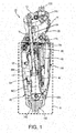
Fig. 1 is a sectional structual view of an artificial leg according to one embodiment of the present invention, in which a knee coupling is in a fully extended state; -
Fig. 2 is a sectional structural view of the artificial leg ofFig. 1 , in which the knee coupling is in a bent state; -
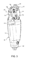
Fig. 3 is a perspective view showing an outer appearance of the artificial leg ofFig. 1 ; -
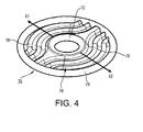
Fig. 4 is a perspective view showing a first example of a bellows packing member used in the present invention; -
Fig. 5 is an enlarged sectional view of an attachment part of the bellows packing member; -
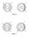
Fig. 6 is a plan view showing a second example of the bellows packing member; -
Fig. 7 is a plan view showing a third example of the bellows packing member; -
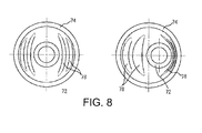
Fig. 8 is a plan view showing a fourth example of the bellows packing member; and -
Fig. 9 is a sectional structual view of a single-axis connection artificial leg to which the present invention is applied. -
Figs. 1 through 3 show a multi-axis artificial leg according to one embodiment of the present invention, and especially, it shows a knee coupling portion thereof mostly. Anartificial leg 10, that is a thigh artificial leg, comprises anupper member 12 located at an upper side of the knee, and alower member 14 located at a lower side of the knee and bendably or swingably connected to theupper member 12 so as to enable the knee to bend. Theupper member 12 integrally supports at an upper central part thereof analignment block 122. Analignment block 122 is adapted to attach a socket, not shown, thereto. Thealignment block 122 supports the load of a wearer of theartificial leg 10 through a thigh part that is received in the socket. On the other hand, thelower member 14 is also provided at a lower central part thereof with anotheralignment block 142,. Thisalignment block 142 is adapted to attach a leg member, that supports a foot part, thereto. - The upper and
lower members knee coupling 20. Theknee coupling 20 is composed of a four-node link mechanism. The four-node link mechanism is a constrained chain that is obtained by rotatably connecting four links. Each of the above-mentioned upper andlower members front link 16 and the other is arear link 18. Each of those twolinks rear links knee coupling 20 in cooperation with each other. - Here, the
upper member 12 has a plate-like configuration that includes twoplate parts lower member 14 has a frame-like configuration that defines an internal space. The frame14, that is a lower member, has anupper opening 14u at an upper side facing theupper member 12 and alower opening 14d at a lower side opposite thereto. Theframe 14 has a front opening at a front surface portion facing the internal parts (for examples, a battery and a control board). - In the
artificial leg 10, ashell structure 30, that defines an internal space, is composed of aframe 14 that is the lower member. Received in the internal space are abattery 40 and acontrol substrate 42 for electronical control, and ahydraulic cylinder 50 for assisting or limiting the movement of theknee coupling 20. Thus, thelower opening 14d of theframe 14 is hermetical sealed by thealignment block 142, and the front opening is hermetically sealed by theframe cover 144 in cooperation with the frame packing. By virtue of the foregoing arrangement, a water-proof property and a dust-proof property can be provided to the peripheral side surface and the lower part of theshell structure 30 surrounding thehydraulic cylinder 50 that is the cylinder device. - In order to form the
artificial leg 10 into a hermetically sealed type, it is required to completely block the internal space of theshell structure 30, that is chiefly composed of theframe 14, from outside. For this purpose, the portion of anupper opening 14u of theframe 14 is required to be effectively hermetically sealed. - In this invention, the portion of the
upper opening 14u, i.e., the upper opening of theshell structure 30 is hermetically sealed by the specificbellows packing member 70. As a result, theartificial leg 10 is formed into the hermetically sealed type in which the portion S indicated by broken lines inFig. 1 is waterproofed and dustproofed by theshell structure 30 and thebellows packing member 70. - The
hydraulic cylinder 50, that is the cylinder device, comprises acylinder body 52 adapted to define acylinder hole 502 and containing apiston 504 in thecylinder hole 502, and arod member 54 supporting thepiston 504 at one end thereof and extending from thecylinder body 52 and then passing through theupper opening 14u so as to be supported by theupper member 12. In thehydraulic cylinder 50, ahead end 52h of thecylinder body 52 is rotatably supported by a lower part of theframe 14 and arod end 54r of therod member 54 is rotatably supported by theupper member 12. - It is well known that such
hydraulic cylinder 50 limits the movement of theknee coupling 20 in accordance with the flow resistance of the hydraulic oil passing through a restriction. As can be seen from the comparison betweenFig. 1 showing a fully extended state andFig. 2 showing a slightly extended state, when theknee coupling 20 is moved, therod member 54 is expanded and contracted with respect to thecylinder body 52 and swung about the supporting point of the portion of thehead end 52h together with thecylinder body 52. -
Fig. 4 shows a first example of the bellows packing member according to the present invention andFig. 5 shows the bellows packing member attached to theartificial leg 10. Thebellows packing member 70 of the first example will now be described with reference to thoseFigs. 4 and5 . - The
bellows packing member 70 is a molded product of chloroprene rubber. Thebellows packing member 70 comprises aninner bead 72 for defining a hole large enough for passing therod member 54 therethrough, anouter bead 74 concentrically surrounding the outside of theinner bead 72, and a bellows packingbody part 76 disposed between the outer andinner beads inner beads inner beads body part 76 has a smaller thickness (for example, about 0.5 mm) than the radius of each bead and includes a plurality of irregular orwavy corrugations 78 for deformation. Thecorrugations 78 are arranged line symmetrically with respect to theinner bead 72. The height of eachcorrugation 78 is smaller (for example, about 2.5 mm) than the distance from theinner bead 72 to theouter bead 74 when the bellows packingbody part 76 is in a non-deformed state. - The
bellows packing member 70 are supported by being fit at the portion of the outer andinner beads outer bead 74 is fit into aring groove 32 of the inner pheriphery of theshell structure 30, while theinner bead 72 is fit into aring groove 82 of the outer periphery of acylindrical rod guide 80. Here, theouter bead 74 is retained in a predetermined position even if theknee coupling 20 should bend. In contrast, theinner bead 72 moves in the predetermined radial directions (the directions as indicated by arrows X1 and X2 ofFig. 4 ) of theouter bead 74. Since theinner bead 72 makes such movement, there is a possibility that theinner bead 72 escapes from thering groove 82. In order to prevent this possible occurrence, thering groove 82 is preferably provided at an opening part thereof with an escape prevention stopper 84. Thecylindrical rod guide 80 is supported on an upper part of thecylinder body 52 such that the expanding/contracting rod member 54 is guided by theguide surface 86 of the inner periphery. - The directions as indicated by arrows X1, X2 of
Fig. 4 (i.e. the deforming directions of the bellows packing body part 76) correspond to the swinging directions of therod member 54. In other words, the swinging directions are the predetermined directions and thus, when theknee coupling 20 moves, the bellows packingbody part 76 receives a force directing in the predetermined directions in accordance with the swinging movement thereof. - In order to prevent noise from occurring caused by the deformation of the
bellows packing member 70 to which the above-mentioned force is exerted, it is designed such that the deforming portion of thecorrugations 78 will not adversely affect the rest portion continuous thereto or other corrugations. That is, eachcorrugation 78 is less curved than an imaginary circle between the inner andouter beads corrugation 78 reaches theouter bead 74 or are located at positions closer to theouter bead 74 than theinner bead 72. In addition to the first example shown inFig. 4 , in the second example shown inFig. 6 and in the third example shown inFig. 7 , thecorrugations 78 are differently arranged and both ends of eachcorrugation 78 are connected to theouter bead 74. Moreover, in the example ofFig. 8 , both ends of eachcorrugation 78 do not reach theouter bead 74. - Although description has been made with respect to the cases wherein the present invention is applied to a multi-axis artificial leg, the present invention can also be applied to a single-axis artificial leg.
Fig. 9 shows one example of a single-axisartificial leg 100 according to the present invention. In this single-axisartificial leg 100, abattery 400, a control board 420, etc. for electronical control are built in an internal space of theshell structure 300 in addition to acylinder body 520 of apneumatic cylinder 500 that is a cylinder device. - A
rod member 540 of thepneumatic cylinder 500 extends from thecylinder body 520 upto anupper member 120. Here again, in order to hermetically seal the upper opening part of theshell structure 300, abellows packing member 700 is used. Since thebellows packing member 700 is larger in the amount of deformation required than thebellows packing member 70, the number of the corrugations 780 is doubled. However, thebellows packing member 700 is the same as the previously mentioned one in the respect that it comprises aninner bead 720, anouter bead 740 and a bellows packing body part 760 which connects the inner andouter beads outer beads - The power sources for the
artificial legs batteries shell structures shell structures shell structures - The most important thing for the artificial leg is to operate as longer time as possible in a normal state. To this end, in addition to the built-in batteries, an external auxiliary power source (for example, portable batteries or the like) can be utilized. In that case, power can be equally fed to both the microcomputer and the motor system from the built-in batteries, that are the main power source, and the auxiliary power source. However, when the auxiliary power source is used (i.e., when the auxiliary power source is connected through the connector), it is preferable that the motor system which requires larger power consumption, uses only power of the auxiliary power source. Because, in doing so, by suppressing the consumption of the built-in battery as a main power source, a remaining quantity of more than a predetermined value can be obtained in the batteries themselves. Moreover, the possibility of the malfunction of the microcomputer caused by temporary voltage decrease which is caused by the operation of the motor system, even when the remaining quantity of the batteries is reduced. In addition, for the hermetically sealed type artificial leg, it is preferable from the view point of hermetical sealing that the connector for connecting the auxiliary power supply and the charging connector are formed into one connector and disposed at the inner side of the hermetically sealed cover 150 (
Fig. 3 ) which can be opened/closed by the artificial leg wearer with respect to the shell structure. -
- 10.....multi-axis artificial leg
- 12.....upper member
- 14.....lower member
- 20.....knee coupling
- 30.....shell structure
- 50.....hydraulic cylinder (cylinder device)
- 52.....cylinder body
- 54.....rod member
- 70.....bellows packing member
- 72.....inner bead
- 74.....outer bead
- 76.....bellows packing body part
- 78.....corrugation
- 80.....rod guide
- 100.....single-axis artificial leg
- 120.....upper member
- 300.....shell structure
- 500.....pneumatic cylinder
- 520.....cylinder body
- 540.....rod member
- 700.....bellows packing member
- 720.....inner bead
- 740.....outer bead
- 760.....bellows packing body part
- 780.....corrugation
Claims (14)
- An hermetically sealed artificial leg comprising
an upper member for supporting a socket at an upper end thereof,
a lower member for supporting a foot part at a lower end thereof,
a knee coupling for bendably coupling said upper and lower members,
a cylinder device for assisting and/or limiting movement of said knee coupling,
a shell structure for surrounding an outside of said cylinder device, said cylinder device including a cylinder body having an axis, and a rod member extending in a direction of said axis from said cylinder body, said rod member extending from inside of said shell structure to outside thereof, and,
a bellows packing member for hermetically sealing a periphery of said rod member,
wherein said bellows packing member includes:an inner bead defining a hole for receiving said rod member therein and serving as a sealing portion for an inner periphery of said bellows packing member;an outer bead serving as an attachment part to a side of said shell structure and also serving as a sealing portion for the side of said shell structure; and,a bellows packing body part which is a body portion located between said inner and outer beads and which has a plurality of corrugations aligned with each other and which is capable of varying a distance between said inner and outer beads, andwherein each of said corrugations is less curved than an imaginary circle between said inner and outer beads and both ends of said corrugation reach the outer bead or are located at positions closer to the outer bead than the inner bead. - The hermetically sealed artificial leg of claim 1, wherein said shell structure and bellows packing member define a hermetically sealed space within said shell structure.
- The hermetically sealed artificial leg of claim 2, wherein said artificial leg is configured to be electronically controlled, and,
a component part for electronical control is received in said hermetically sealed space. - The hermetically sealed artificial leg of claim 1, wherein when said upper and lower members are moved to bend, said rod member is expanded and contracted in an axial direction of said cylinder body and at the same time, swung in a direction crossing said axis to deform said bellows packing body part.
- The hermetically sealed artificial leg of claim 1, wherein said cylinder body includes a rod guide for guiding said rod member, and said rod guide supports said inner bead.
- The hermetically sealed artificial leg of claim 5, wherein said rod guide having a cylindrical shape is provided at an inner peripheral side thereof with a guide surface for guiding an outer periphery of said rod member and at an outer peripheral side thereof with a ring groove into which said inner bead is fit.
- The hermetically sealed artificial leg of claim 6, wherein said ring groove is provided at an opening part thereof with a stopper adapted to prevent said inner bead from escaping.
- The hermetically sealed artificial leg of claim 4, wherein when said upper and lower members are moved to bend, said inner bead moves in a radial direction of said outer bead in accordance with deformation of said bellows packing body part.
- The hermetically sealed artificial leg of claim 1, wherein a rod end of said rod member of said cylinder device is located on a side of said upper member, while a cylinder head of said cylinder body of said cylinder device is located on a side of said lower member.
- The hermetically sealed artificial leg of claim 9, wherein in a sectional view of said bellows packing member taken in a longitudinal direction of said rod member, said inner and outer beads are in the same height position or said inner bead is located in a position closer to the rod end of said rod member than said outer bead.
- The hermetically sealed artificial leg of claim 1, wherein each of said corrugations in said bellows packing body part keeps a same height position from said inner bead to said outer bead.
- The hermetically sealed artificial leg of claim 11, wherein a height of each corrugation is smaller than a distance from said inner bead to said outer bead, when said bellows packing body part is in a non-deformed state.
- The hermetically sealed artificial leg of claim 1, wherein connection of said knee coupling is made by using either a single-axis or a multi-axis, i.e., a multi-node link.
- The hermetically sealed artificial leg of claim 1, wherein said cylinder device is any one of a hydraulic cylinder, a spring cylinder, a pneumatic cylinder and a linear actuator.
Applications Claiming Priority (1)
| Application Number | Priority Date | Filing Date | Title |
|---|---|---|---|
| PCT/JP2012/072029 WO2014033876A1 (en) | 2012-08-30 | 2012-08-30 | Hermetically sealed artificial leg |
Publications (3)
| Publication Number | Publication Date |
|---|---|
| EP2891473A1 true EP2891473A1 (en) | 2015-07-08 |
| EP2891473A4 EP2891473A4 (en) | 2016-05-18 |
| EP2891473B1 EP2891473B1 (en) | 2020-01-08 |
Family
ID=50182725
Family Applications (1)
| Application Number | Title | Priority Date | Filing Date |
|---|---|---|---|
| EP12883769.7A Active EP2891473B1 (en) | 2012-08-30 | 2012-08-30 | Hermetically sealed artificial leg |
Country Status (5)
| Country | Link |
|---|---|
| US (1) | US9925070B2 (en) |
| EP (1) | EP2891473B1 (en) |
| JP (1) | JP5709237B2 (en) |
| CN (1) | CN104582640B (en) |
| WO (1) | WO2014033876A1 (en) |
Families Citing this family (2)
| Publication number | Priority date | Publication date | Assignee | Title |
|---|---|---|---|---|
| JP2022099089A (en) * | 2020-12-22 | 2022-07-04 | ナブテスコ株式会社 | Artificial leg power consumption calculation system, artificial leg state estimation system, and artificial leg user physical condition estimation system |
| US11850171B2 (en) * | 2021-03-03 | 2023-12-26 | Össur Iceland Ehf | Waterproof prosthetic knee and removable covering therefor |
Family Cites Families (29)
| Publication number | Priority date | Publication date | Assignee | Title |
|---|---|---|---|---|
| US2397597A (en) * | 1944-07-17 | 1946-04-02 | Goetze Gasket & Packing Co Inc | Gasket |
| US2774621A (en) * | 1954-02-01 | 1956-12-18 | Connecticut Hard Rubber Co | Flexible gaskets |
| US2983533A (en) * | 1957-01-22 | 1961-05-09 | A P D Co | Sealing ring |
| US3542382A (en) * | 1968-04-26 | 1970-11-24 | Foster M Hagmann | Seal |
| JPS5513065A (en) | 1978-07-14 | 1980-01-29 | Shinei Kk | Artificial feed for silkworm |
| DE2841999C2 (en) | 1978-09-27 | 1981-11-26 | Otto Bock, Orthopädische Industrie KG, 3428 Duderstadt | Artificial knee joint |
| DE3134015C2 (en) * | 1981-08-28 | 1988-04-14 | Elring Dichtungswerke Gmbh, 7012 Fellbach | Flat gasket and process for their manufacture |
| US5507420A (en) * | 1990-02-02 | 1996-04-16 | Aervoe-Pacific Company, Inc. | Reusable high efficiency propellant driven liquid product dispenser apparatus |
| JP2521155Y2 (en) * | 1990-08-07 | 1996-12-25 | 石川ガスケット 株式会社 | Insulating metal laminated gasket |
| US5248154A (en) * | 1991-10-07 | 1993-09-28 | Poly-Tec Products, Inc. | Bidirectional gasket |
| US5443521A (en) * | 1992-12-21 | 1995-08-22 | Mauch Laboratories, Inc. | Hydraulic control unit for prosthetic leg |
| GB9312131D0 (en) * | 1993-06-11 | 1993-07-28 | Blatchford & Sons Ltd | Prosthesis control system |
| JP3571757B2 (en) * | 1994-03-25 | 2004-09-29 | 株式会社今仙技術研究所 | Prosthesis |
| DE4410730C1 (en) * | 1994-03-28 | 1995-06-08 | Biedermann Motech Gmbh | Servo-hydraulic swing phase control for artificial knee joint |
| US6092811A (en) * | 1996-04-30 | 2000-07-25 | Jamco Products, Llc | Hybrid gasket |
| JP2991139B2 (en) * | 1996-12-11 | 1999-12-20 | 株式会社啓愛義肢材料販売所 | Knee joint |
| US5948021A (en) | 1998-02-24 | 1999-09-07 | Hosmer-Dorrance Corporation | Hydraulic cylinders for limb gait control |
| JP3570619B2 (en) | 1999-11-15 | 2004-09-29 | 株式会社ナブコ | Air cylinder device for artificial legs |
| JP3957959B2 (en) | 2000-08-22 | 2007-08-15 | 株式会社今仙技術研究所 | Prosthetic knee joint structure |
| EP1531766B1 (en) | 2002-08-22 | 2012-08-01 | Victhom Human Bionics Inc. | Actuated leg prosthesis for above-knee amputees |
| US6845983B1 (en) * | 2002-09-13 | 2005-01-25 | Acadia Elastomers Corporation | Gasket with outer edge damping channel and method and apparatus for manufacturing same |
| US20050111689A1 (en) * | 2003-11-21 | 2005-05-26 | True Technologies Inc. | Loudspeaker with assembly and performance improvements |
| US8048172B2 (en) | 2005-09-01 | 2011-11-01 | össur hf | Actuator assembly for prosthetic or orthotic joint |
| DE102006009510A1 (en) * | 2006-02-27 | 2007-09-06 | Otto Bock Healthcare Ip Gmbh & Co. Kg | hip prosthesis |
| DE102007032090B4 (en) * | 2007-07-09 | 2016-08-11 | Otto Bock Healthcare Gmbh | Orthopedic fluid damper |
| EP2250977B1 (en) * | 2008-03-07 | 2014-07-23 | Nabtesco Corporation | Knee joint including manual lock mechanism and artificial thigh |
| DE102009009169B4 (en) * | 2009-02-16 | 2011-12-01 | Federal-Mogul Sealing Systems Gmbh | Flat gasket with wavy stopper |
| CN201500215U (en) * | 2009-08-31 | 2010-06-09 | 英华格假肢(厦门)企业有限公司 | Double-drum pneumatic cylinder for knee joint of disable person |
| WO2012125562A1 (en) * | 2011-03-11 | 2012-09-20 | Iwalk, Inc. | Biomimetic joint actuators |
-
2012
- 2012-08-30 US US14/424,239 patent/US9925070B2/en active Active
- 2012-08-30 EP EP12883769.7A patent/EP2891473B1/en active Active
- 2012-08-30 CN CN201280075565.5A patent/CN104582640B/en active Active
- 2012-08-30 WO PCT/JP2012/072029 patent/WO2014033876A1/en not_active Ceased
- 2012-08-30 JP JP2014532650A patent/JP5709237B2/en active Active
Also Published As
| Publication number | Publication date |
|---|---|
| EP2891473A4 (en) | 2016-05-18 |
| JPWO2014033876A1 (en) | 2016-08-08 |
| EP2891473B1 (en) | 2020-01-08 |
| WO2014033876A1 (en) | 2014-03-06 |
| JP5709237B2 (en) | 2015-04-30 |
| US9925070B2 (en) | 2018-03-27 |
| CN104582640A (en) | 2015-04-29 |
| CN104582640B (en) | 2016-05-18 |
| US20150250622A1 (en) | 2015-09-10 |
Similar Documents
| Publication | Publication Date | Title |
|---|---|---|
| JP7475143B2 (en) | Leg Exoskeleton System and Method | |
| US8342586B2 (en) | Robot hand and humanoid robot having the same | |
| KR101126504B1 (en) | Cable or the like protection and guide device | |
| Kobayashi et al. | Development of muscle suit for upper limb | |
| US20110303042A1 (en) | Industrial robot | |
| US20160016307A1 (en) | Connecting module and motion assistance apparatus including the same | |
| CN106489030A (en) | Actuator devices, power-assisted robot and anthropomorphic robot | |
| EP2891473B1 (en) | Hermetically sealed artificial leg | |
| KR101922556B1 (en) | Muscular strength assistance device using the shape memory alloy spring | |
| CN109421039A (en) | Robot and parallel link robot | |
| Sareh et al. | A 7.5 mm Steiner chain fibre-optic system for multi-segment flex sensing | |
| CN116001948A (en) | Electro-hydraulic compound driving explosion-proof leg-foot robot | |
| CN110253561A (en) | Flexible drives for bending motion | |
| CN218170411U (en) | Mechanical arm | |
| CN102374226A (en) | Sleeve, hinge structure, and portable electronic device using hinge structure | |
| WO2018105470A1 (en) | Actuator device and joint movement assisting device | |
| CN107283393A (en) | Exoskeleton robot and its hip joint | |
| CN220578410U (en) | Transmission bottle | |
| RU146585U1 (en) | GATE VALVE (OPTIONS) | |
| CN216933920U (en) | An actuator anti-bias mechanism | |
| WO2024254827A1 (en) | Harness protection device for industrial robot | |
| CN215681997U (en) | Industrial robot dual output axle servo motor | |
| KR102363822B1 (en) | Sensor assembly and measurement device using the same | |
| CN219277667U (en) | Electro-hydraulic compound driving explosion-proof leg-foot robot | |
| CN113771084A (en) | Knee joint elastic driving device and exoskeleton robot |
Legal Events
| Date | Code | Title | Description |
|---|---|---|---|
| PUAI | Public reference made under article 153(3) epc to a published international application that has entered the european phase |
Free format text: ORIGINAL CODE: 0009012 |
|
| 17P | Request for examination filed |
Effective date: 20150226 |
|
| AK | Designated contracting states |
Kind code of ref document: A1 Designated state(s): AL AT BE BG CH CY CZ DE DK EE ES FI FR GB GR HR HU IE IS IT LI LT LU LV MC MK MT NL NO PL PT RO RS SE SI SK SM TR |
|
| AX | Request for extension of the european patent |
Extension state: BA ME |
|
| DAX | Request for extension of the european patent (deleted) | ||
| RA4 | Supplementary search report drawn up and despatched (corrected) |
Effective date: 20160420 |
|
| RIC1 | Information provided on ipc code assigned before grant |
Ipc: A61F 2/50 20060101ALI20160414BHEP Ipc: A61F 2/66 20060101ALI20160414BHEP Ipc: A61F 2/64 20060101AFI20160414BHEP Ipc: A61F 2/70 20060101ALI20160414BHEP Ipc: A61F 2/60 20060101ALI20160414BHEP |
|
| STAA | Information on the status of an ep patent application or granted ep patent |
Free format text: STATUS: EXAMINATION IS IN PROGRESS |
|
| 17Q | First examination report despatched |
Effective date: 20161220 |
|
| GRAP | Despatch of communication of intention to grant a patent |
Free format text: ORIGINAL CODE: EPIDOSNIGR1 |
|
| STAA | Information on the status of an ep patent application or granted ep patent |
Free format text: STATUS: GRANT OF PATENT IS INTENDED |
|
| INTG | Intention to grant announced |
Effective date: 20191001 |
|
| GRAS | Grant fee paid |
Free format text: ORIGINAL CODE: EPIDOSNIGR3 |
|
| GRAA | (expected) grant |
Free format text: ORIGINAL CODE: 0009210 |
|
| STAA | Information on the status of an ep patent application or granted ep patent |
Free format text: STATUS: THE PATENT HAS BEEN GRANTED |
|
| AK | Designated contracting states |
Kind code of ref document: B1 Designated state(s): AL AT BE BG CH CY CZ DE DK EE ES FI FR GB GR HR HU IE IS IT LI LT LU LV MC MK MT NL NO PL PT RO RS SE SI SK SM TR |
|
| REG | Reference to a national code |
Ref country code: GB Ref legal event code: FG4D |
|
| REG | Reference to a national code |
Ref country code: CH Ref legal event code: EP |
|
| REG | Reference to a national code |
Ref country code: DE Ref legal event code: R096 Ref document number: 602012067192 Country of ref document: DE |
|
| REG | Reference to a national code |
Ref country code: IE Ref legal event code: FG4D |
|
| REG | Reference to a national code |
Ref country code: AT Ref legal event code: REF Ref document number: 1221753 Country of ref document: AT Kind code of ref document: T Effective date: 20200215 |
|
| REG | Reference to a national code |
Ref country code: NL Ref legal event code: MP Effective date: 20200108 |
|
| REG | Reference to a national code |
Ref country code: LT Ref legal event code: MG4D |
|
| PG25 | Lapsed in a contracting state [announced via postgrant information from national office to epo] |
Ref country code: RS Free format text: LAPSE BECAUSE OF FAILURE TO SUBMIT A TRANSLATION OF THE DESCRIPTION OR TO PAY THE FEE WITHIN THE PRESCRIBED TIME-LIMIT Effective date: 20200108 Ref country code: FI Free format text: LAPSE BECAUSE OF FAILURE TO SUBMIT A TRANSLATION OF THE DESCRIPTION OR TO PAY THE FEE WITHIN THE PRESCRIBED TIME-LIMIT Effective date: 20200108 Ref country code: LT Free format text: LAPSE BECAUSE OF FAILURE TO SUBMIT A TRANSLATION OF THE DESCRIPTION OR TO PAY THE FEE WITHIN THE PRESCRIBED TIME-LIMIT Effective date: 20200108 Ref country code: NL Free format text: LAPSE BECAUSE OF FAILURE TO SUBMIT A TRANSLATION OF THE DESCRIPTION OR TO PAY THE FEE WITHIN THE PRESCRIBED TIME-LIMIT Effective date: 20200108 Ref country code: PT Free format text: LAPSE BECAUSE OF FAILURE TO SUBMIT A TRANSLATION OF THE DESCRIPTION OR TO PAY THE FEE WITHIN THE PRESCRIBED TIME-LIMIT Effective date: 20200531 Ref country code: NO Free format text: LAPSE BECAUSE OF FAILURE TO SUBMIT A TRANSLATION OF THE DESCRIPTION OR TO PAY THE FEE WITHIN THE PRESCRIBED TIME-LIMIT Effective date: 20200408 |
|
| PG25 | Lapsed in a contracting state [announced via postgrant information from national office to epo] |
Ref country code: HR Free format text: LAPSE BECAUSE OF FAILURE TO SUBMIT A TRANSLATION OF THE DESCRIPTION OR TO PAY THE FEE WITHIN THE PRESCRIBED TIME-LIMIT Effective date: 20200108 Ref country code: BG Free format text: LAPSE BECAUSE OF FAILURE TO SUBMIT A TRANSLATION OF THE DESCRIPTION OR TO PAY THE FEE WITHIN THE PRESCRIBED TIME-LIMIT Effective date: 20200408 Ref country code: IS Free format text: LAPSE BECAUSE OF FAILURE TO SUBMIT A TRANSLATION OF THE DESCRIPTION OR TO PAY THE FEE WITHIN THE PRESCRIBED TIME-LIMIT Effective date: 20200508 Ref country code: SE Free format text: LAPSE BECAUSE OF FAILURE TO SUBMIT A TRANSLATION OF THE DESCRIPTION OR TO PAY THE FEE WITHIN THE PRESCRIBED TIME-LIMIT Effective date: 20200108 Ref country code: GR Free format text: LAPSE BECAUSE OF FAILURE TO SUBMIT A TRANSLATION OF THE DESCRIPTION OR TO PAY THE FEE WITHIN THE PRESCRIBED TIME-LIMIT Effective date: 20200409 Ref country code: LV Free format text: LAPSE BECAUSE OF FAILURE TO SUBMIT A TRANSLATION OF THE DESCRIPTION OR TO PAY THE FEE WITHIN THE PRESCRIBED TIME-LIMIT Effective date: 20200108 |
|
| REG | Reference to a national code |
Ref country code: DE Ref legal event code: R097 Ref document number: 602012067192 Country of ref document: DE |
|
| PG25 | Lapsed in a contracting state [announced via postgrant information from national office to epo] |
Ref country code: CZ Free format text: LAPSE BECAUSE OF FAILURE TO SUBMIT A TRANSLATION OF THE DESCRIPTION OR TO PAY THE FEE WITHIN THE PRESCRIBED TIME-LIMIT Effective date: 20200108 Ref country code: RO Free format text: LAPSE BECAUSE OF FAILURE TO SUBMIT A TRANSLATION OF THE DESCRIPTION OR TO PAY THE FEE WITHIN THE PRESCRIBED TIME-LIMIT Effective date: 20200108 Ref country code: SK Free format text: LAPSE BECAUSE OF FAILURE TO SUBMIT A TRANSLATION OF THE DESCRIPTION OR TO PAY THE FEE WITHIN THE PRESCRIBED TIME-LIMIT Effective date: 20200108 Ref country code: SM Free format text: LAPSE BECAUSE OF FAILURE TO SUBMIT A TRANSLATION OF THE DESCRIPTION OR TO PAY THE FEE WITHIN THE PRESCRIBED TIME-LIMIT Effective date: 20200108 Ref country code: DK Free format text: LAPSE BECAUSE OF FAILURE TO SUBMIT A TRANSLATION OF THE DESCRIPTION OR TO PAY THE FEE WITHIN THE PRESCRIBED TIME-LIMIT Effective date: 20200108 Ref country code: EE Free format text: LAPSE BECAUSE OF FAILURE TO SUBMIT A TRANSLATION OF THE DESCRIPTION OR TO PAY THE FEE WITHIN THE PRESCRIBED TIME-LIMIT Effective date: 20200108 Ref country code: ES Free format text: LAPSE BECAUSE OF FAILURE TO SUBMIT A TRANSLATION OF THE DESCRIPTION OR TO PAY THE FEE WITHIN THE PRESCRIBED TIME-LIMIT Effective date: 20200108 |
|
| PLBE | No opposition filed within time limit |
Free format text: ORIGINAL CODE: 0009261 |
|
| STAA | Information on the status of an ep patent application or granted ep patent |
Free format text: STATUS: NO OPPOSITION FILED WITHIN TIME LIMIT |
|
| REG | Reference to a national code |
Ref country code: AT Ref legal event code: MK05 Ref document number: 1221753 Country of ref document: AT Kind code of ref document: T Effective date: 20200108 |
|
| 26N | No opposition filed |
Effective date: 20201009 |
|
| PG25 | Lapsed in a contracting state [announced via postgrant information from national office to epo] |
Ref country code: AT Free format text: LAPSE BECAUSE OF FAILURE TO SUBMIT A TRANSLATION OF THE DESCRIPTION OR TO PAY THE FEE WITHIN THE PRESCRIBED TIME-LIMIT Effective date: 20200108 Ref country code: IT Free format text: LAPSE BECAUSE OF FAILURE TO SUBMIT A TRANSLATION OF THE DESCRIPTION OR TO PAY THE FEE WITHIN THE PRESCRIBED TIME-LIMIT Effective date: 20200108 |
|
| PG25 | Lapsed in a contracting state [announced via postgrant information from national office to epo] |
Ref country code: PL Free format text: LAPSE BECAUSE OF FAILURE TO SUBMIT A TRANSLATION OF THE DESCRIPTION OR TO PAY THE FEE WITHIN THE PRESCRIBED TIME-LIMIT Effective date: 20200108 Ref country code: SI Free format text: LAPSE BECAUSE OF FAILURE TO SUBMIT A TRANSLATION OF THE DESCRIPTION OR TO PAY THE FEE WITHIN THE PRESCRIBED TIME-LIMIT Effective date: 20200108 |
|
| PG25 | Lapsed in a contracting state [announced via postgrant information from national office to epo] |
Ref country code: MC Free format text: LAPSE BECAUSE OF FAILURE TO SUBMIT A TRANSLATION OF THE DESCRIPTION OR TO PAY THE FEE WITHIN THE PRESCRIBED TIME-LIMIT Effective date: 20200108 |
|
| REG | Reference to a national code |
Ref country code: CH Ref legal event code: PL |
|
| GBPC | Gb: european patent ceased through non-payment of renewal fee |
Effective date: 20200830 |
|
| PG25 | Lapsed in a contracting state [announced via postgrant information from national office to epo] |
Ref country code: LI Free format text: LAPSE BECAUSE OF NON-PAYMENT OF DUE FEES Effective date: 20200831 Ref country code: CH Free format text: LAPSE BECAUSE OF NON-PAYMENT OF DUE FEES Effective date: 20200831 Ref country code: LU Free format text: LAPSE BECAUSE OF NON-PAYMENT OF DUE FEES Effective date: 20200830 |
|
| REG | Reference to a national code |
Ref country code: BE Ref legal event code: MM Effective date: 20200831 |
|
| PG25 | Lapsed in a contracting state [announced via postgrant information from national office to epo] |
Ref country code: FR Free format text: LAPSE BECAUSE OF NON-PAYMENT OF DUE FEES Effective date: 20200831 |
|
| PG25 | Lapsed in a contracting state [announced via postgrant information from national office to epo] |
Ref country code: BE Free format text: LAPSE BECAUSE OF NON-PAYMENT OF DUE FEES Effective date: 20200831 Ref country code: GB Free format text: LAPSE BECAUSE OF NON-PAYMENT OF DUE FEES Effective date: 20200830 Ref country code: IE Free format text: LAPSE BECAUSE OF NON-PAYMENT OF DUE FEES Effective date: 20200830 |
|
| PG25 | Lapsed in a contracting state [announced via postgrant information from national office to epo] |
Ref country code: TR Free format text: LAPSE BECAUSE OF FAILURE TO SUBMIT A TRANSLATION OF THE DESCRIPTION OR TO PAY THE FEE WITHIN THE PRESCRIBED TIME-LIMIT Effective date: 20200108 Ref country code: MT Free format text: LAPSE BECAUSE OF FAILURE TO SUBMIT A TRANSLATION OF THE DESCRIPTION OR TO PAY THE FEE WITHIN THE PRESCRIBED TIME-LIMIT Effective date: 20200108 Ref country code: CY Free format text: LAPSE BECAUSE OF FAILURE TO SUBMIT A TRANSLATION OF THE DESCRIPTION OR TO PAY THE FEE WITHIN THE PRESCRIBED TIME-LIMIT Effective date: 20200108 |
|
| PG25 | Lapsed in a contracting state [announced via postgrant information from national office to epo] |
Ref country code: MK Free format text: LAPSE BECAUSE OF FAILURE TO SUBMIT A TRANSLATION OF THE DESCRIPTION OR TO PAY THE FEE WITHIN THE PRESCRIBED TIME-LIMIT Effective date: 20200108 Ref country code: AL Free format text: LAPSE BECAUSE OF FAILURE TO SUBMIT A TRANSLATION OF THE DESCRIPTION OR TO PAY THE FEE WITHIN THE PRESCRIBED TIME-LIMIT Effective date: 20200108 |
|
| P01 | Opt-out of the competence of the unified patent court (upc) registered |
Effective date: 20230523 |
|
| PGFP | Annual fee paid to national office [announced via postgrant information from national office to epo] |
Ref country code: DE Payment date: 20250820 Year of fee payment: 14 |