EP2891465A1 - Medical system and operation method - Google Patents
Medical system and operation method Download PDFInfo
- Publication number
- EP2891465A1 EP2891465A1 EP13832228.4A EP13832228A EP2891465A1 EP 2891465 A1 EP2891465 A1 EP 2891465A1 EP 13832228 A EP13832228 A EP 13832228A EP 2891465 A1 EP2891465 A1 EP 2891465A1
- Authority
- EP
- European Patent Office
- Prior art keywords
- held
- holding
- medical system
- treatment
- modification
- Prior art date
- Legal status (The legal status is an assumption and is not a legal conclusion. Google has not performed a legal analysis and makes no representation as to the accuracy of the status listed.)
- Withdrawn
Links
- 238000000034 method Methods 0.000 title claims description 7
- 238000003780 insertion Methods 0.000 claims description 16
- 230000037431 insertion Effects 0.000 claims description 16
- 238000012986 modification Methods 0.000 description 65
- 230000004048 modification Effects 0.000 description 65
- 238000010586 diagram Methods 0.000 description 24
- 230000000694 effects Effects 0.000 description 18
- 238000003384 imaging method Methods 0.000 description 5
- 238000005286 illumination Methods 0.000 description 4
- 229920005989 resin Polymers 0.000 description 4
- 239000011347 resin Substances 0.000 description 4
- 238000005452 bending Methods 0.000 description 2
- 239000012634 fragment Substances 0.000 description 2
- 239000000463 material Substances 0.000 description 2
- 229910000684 Cobalt-chrome Inorganic materials 0.000 description 1
- YCKRFDGAMUMZLT-UHFFFAOYSA-N Fluorine atom Chemical compound [F] YCKRFDGAMUMZLT-UHFFFAOYSA-N 0.000 description 1
- 229910000861 Mg alloy Inorganic materials 0.000 description 1
- 239000004677 Nylon Substances 0.000 description 1
- 239000004743 Polypropylene Substances 0.000 description 1
- 229910001069 Ti alloy Inorganic materials 0.000 description 1
- RTAQQCXQSZGOHL-UHFFFAOYSA-N Titanium Chemical compound [Ti] RTAQQCXQSZGOHL-UHFFFAOYSA-N 0.000 description 1
- 238000010521 absorption reaction Methods 0.000 description 1
- 229910045601 alloy Inorganic materials 0.000 description 1
- 239000000956 alloy Substances 0.000 description 1
- 239000010952 cobalt-chrome Substances 0.000 description 1
- 229920001577 copolymer Polymers 0.000 description 1
- 230000007423 decrease Effects 0.000 description 1
- 238000013461 design Methods 0.000 description 1
- 238000003745 diagnosis Methods 0.000 description 1
- 239000003814 drug Substances 0.000 description 1
- 229940079593 drug Drugs 0.000 description 1
- 229910052731 fluorine Inorganic materials 0.000 description 1
- 239000011737 fluorine Substances 0.000 description 1
- 229910001000 nickel titanium Inorganic materials 0.000 description 1
- 229920001778 nylon Polymers 0.000 description 1
- 230000002093 peripheral effect Effects 0.000 description 1
- 229920000728 polyester Polymers 0.000 description 1
- -1 polypropylene Polymers 0.000 description 1
- 229920001155 polypropylene Polymers 0.000 description 1
- 238000012545 processing Methods 0.000 description 1
- 239000000523 sample Substances 0.000 description 1
- 239000010935 stainless steel Substances 0.000 description 1
- 229910001220 stainless steel Inorganic materials 0.000 description 1
- 238000012360 testing method Methods 0.000 description 1
- 229910052719 titanium Inorganic materials 0.000 description 1
- 239000010936 titanium Substances 0.000 description 1
- PAPBSGBWRJIAAV-UHFFFAOYSA-N ε-Caprolactone Chemical compound O=C1CCCCCO1 PAPBSGBWRJIAAV-UHFFFAOYSA-N 0.000 description 1
Images






Classifications
-
- A—HUMAN NECESSITIES
- A61—MEDICAL OR VETERINARY SCIENCE; HYGIENE
- A61B—DIAGNOSIS; SURGERY; IDENTIFICATION
- A61B17/00—Surgical instruments, devices or methods
- A61B17/28—Surgical forceps
- A61B17/29—Forceps for use in minimally invasive surgery
-
- A—HUMAN NECESSITIES
- A61—MEDICAL OR VETERINARY SCIENCE; HYGIENE
- A61B—DIAGNOSIS; SURGERY; IDENTIFICATION
- A61B34/00—Computer-aided surgery; Manipulators or robots specially adapted for use in surgery
- A61B34/30—Surgical robots
-
- A—HUMAN NECESSITIES
- A61—MEDICAL OR VETERINARY SCIENCE; HYGIENE
- A61B—DIAGNOSIS; SURGERY; IDENTIFICATION
- A61B17/00—Surgical instruments, devices or methods
- A61B17/32—Surgical cutting instruments
- A61B17/3205—Excision instruments
- A61B17/32056—Surgical snare instruments
-
- A—HUMAN NECESSITIES
- A61—MEDICAL OR VETERINARY SCIENCE; HYGIENE
- A61B—DIAGNOSIS; SURGERY; IDENTIFICATION
- A61B34/00—Computer-aided surgery; Manipulators or robots specially adapted for use in surgery
- A61B34/30—Surgical robots
- A61B34/37—Leader-follower robots
-
- A—HUMAN NECESSITIES
- A61—MEDICAL OR VETERINARY SCIENCE; HYGIENE
- A61B—DIAGNOSIS; SURGERY; IDENTIFICATION
- A61B90/00—Instruments, implements or accessories specially adapted for surgery or diagnosis and not covered by any of the groups A61B1/00 - A61B50/00, e.g. for luxation treatment or for protecting wound edges
- A61B90/50—Supports for surgical instruments, e.g. articulated arms
-
- A—HUMAN NECESSITIES
- A61—MEDICAL OR VETERINARY SCIENCE; HYGIENE
- A61N—ELECTROTHERAPY; MAGNETOTHERAPY; RADIATION THERAPY; ULTRASOUND THERAPY
- A61N1/00—Electrotherapy; Circuits therefor
- A61N1/02—Details
- A61N1/04—Electrodes
- A61N1/05—Electrodes for implantation or insertion into the body, e.g. heart electrode
- A61N1/0517—Esophageal electrodes
-
- A—HUMAN NECESSITIES
- A61—MEDICAL OR VETERINARY SCIENCE; HYGIENE
- A61B—DIAGNOSIS; SURGERY; IDENTIFICATION
- A61B17/00—Surgical instruments, devices or methods
- A61B17/34—Trocars; Puncturing needles
- A61B17/3478—Endoscopic needles, e.g. for infusion
-
- A—HUMAN NECESSITIES
- A61—MEDICAL OR VETERINARY SCIENCE; HYGIENE
- A61B—DIAGNOSIS; SURGERY; IDENTIFICATION
- A61B17/00—Surgical instruments, devices or methods
- A61B2017/0042—Surgical instruments, devices or methods with special provisions for gripping
- A61B2017/00429—Surgical instruments, devices or methods with special provisions for gripping with a roughened portion
- A61B2017/00433—Surgical instruments, devices or methods with special provisions for gripping with a roughened portion knurled
-
- A—HUMAN NECESSITIES
- A61—MEDICAL OR VETERINARY SCIENCE; HYGIENE
- A61B—DIAGNOSIS; SURGERY; IDENTIFICATION
- A61B17/00—Surgical instruments, devices or methods
- A61B17/28—Surgical forceps
- A61B17/29—Forceps for use in minimally invasive surgery
- A61B2017/2901—Details of shaft
- A61B2017/2906—Multiple forceps
-
- A—HUMAN NECESSITIES
- A61—MEDICAL OR VETERINARY SCIENCE; HYGIENE
- A61B—DIAGNOSIS; SURGERY; IDENTIFICATION
- A61B17/00—Surgical instruments, devices or methods
- A61B17/30—Surgical pincettes, i.e. surgical tweezers without pivotal connections
- A61B2017/306—Surgical pincettes, i.e. surgical tweezers without pivotal connections holding by means of suction
-
- A—HUMAN NECESSITIES
- A61—MEDICAL OR VETERINARY SCIENCE; HYGIENE
- A61B—DIAGNOSIS; SURGERY; IDENTIFICATION
- A61B18/00—Surgical instruments, devices or methods for transferring non-mechanical forms of energy to or from the body
- A61B18/04—Surgical instruments, devices or methods for transferring non-mechanical forms of energy to or from the body by heating
- A61B18/12—Surgical instruments, devices or methods for transferring non-mechanical forms of energy to or from the body by heating by passing a current through the tissue to be heated, e.g. high-frequency current
- A61B18/14—Probes or electrodes therefor
- A61B2018/1405—Electrodes having a specific shape
- A61B2018/1422—Hook
-
- A—HUMAN NECESSITIES
- A61—MEDICAL OR VETERINARY SCIENCE; HYGIENE
- A61B—DIAGNOSIS; SURGERY; IDENTIFICATION
- A61B18/00—Surgical instruments, devices or methods for transferring non-mechanical forms of energy to or from the body
- A61B18/04—Surgical instruments, devices or methods for transferring non-mechanical forms of energy to or from the body by heating
- A61B18/12—Surgical instruments, devices or methods for transferring non-mechanical forms of energy to or from the body by heating by passing a current through the tissue to be heated, e.g. high-frequency current
- A61B18/14—Probes or electrodes therefor
- A61B2018/1405—Electrodes having a specific shape
- A61B2018/1425—Needle
-
- A—HUMAN NECESSITIES
- A61—MEDICAL OR VETERINARY SCIENCE; HYGIENE
- A61B—DIAGNOSIS; SURGERY; IDENTIFICATION
- A61B34/00—Computer-aided surgery; Manipulators or robots specially adapted for use in surgery
- A61B34/30—Surgical robots
- A61B2034/301—Surgical robots for introducing or steering flexible instruments inserted into the body, e.g. catheters or endoscopes
Definitions
- the present invention relates to a medical system and an operation method.
- Patent Literature 1 discloses an endoscope treatment system including an endoscope provided with an insertion part inserted into the inside of the body and a treatment tool mounted in the insertion part of the endoscope.
- the treatment tool mounted in the endoscope is detachable from the endoscope and can be received in a receiving part mounted in the endoscope. Furthermore, in Patent Literature 1, forceps are provided as an example of the treatment tool.
- An object of the present invention is to provide a medical system capable of simply changing the direction, position, orientation or the like of a device such as a treatment tool while maintaining the direction of an insertion part, and an operation method of the device such as a treatment tool.
- a medical system includes an insertion part inserted into an inside of a body, an arm part provided on the insertion part and capable of moving with respect to the insertion part, a device disposed in the inside of the body, a holding part provided on the arm part and holding the device, and a part to be held provided on the device and held by the holding part.
- At least one of the holding part and the part to be held may have a restriction part that restricts movement of the device.
- the holding part may have a grip part that grips the part to be held, and the part to be held may have a part to be gripped capable of engaging with the grip part.
- the holding part and the part to be held may have concave-convex shapes engaging with each other.
- the holding part and the part to be held may engage with each other through frictional force.
- a rod-shaped part may be provided on one of the holding part and the part to be held, and a hole to which the rod-shaped part is fitted may be formed in a remaining one of the holding part and the part to be held.
- the part to be held may have a plurality of projection-stripe portions, and the plurality of projection-stripe portions may extend in parallel to one another in a longitudinal axial direction of the device.
- the part to be held may have a plurality of conical-shaped portions having apexes capable of coming in contact with the holding part.
- the insertion part may have an external tube and a device channel formed in the external tube, and the device may have a flexible tube part insertable into the device channel.
- a part of the device is held using a holding part provided on an arm part that is the body provided separately from the device and has at least one degree of freedom, and the arm part is moved, so that the device held by the holding part is moved together with the arm part.
- the medical system and the operation method of a device disposed in the inside of a body it is possible to simply change the direction, position, orientation or the like of the device such as a treatment tool while maintaining the direction of the insertion part.
- Fig. 1 is an overall view of a medical system of the present embodiment.
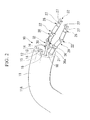
- Fig. 2 is a perspective view showing the structure of a part of the medical system.
- a medical system 1 of the present embodiment is a master-slave type system including a master manipulator 2 operated by an operator Op for treatment, and a slave manipulator 6 provided with an endoscope device 10 for treatment.
- the master manipulator 2 includes master arms 3, a display part 4, and a control part 5.
- the master arms 3 are operated by the operator Op.
- the display part 4 displays video or the like captured using the endoscope device 10 for treatment.
- the control part 5 generates an operation command for operating the slave manipulator 6 on the basis of the operation of the master arms 3.
- the master arms 3 are operation parts provided in order to operate holding tools 20 (which will be described later) mounted in the endoscope device 10 for treatment.
- the master manipulator 2 has the master arms 3 corresponding to the right hand and the left hand of the operator Op.
- Each of the master arms 3 has a multiple joint structure used to operate a joint part 22 of the holding tool 20 having at least one degree of freedom, which will be described later.
- a grip part (not shown) for operating a grip part 26 of the holding tool 20, which will be described later, is provided at an end portion of each of the master arms 3 positioned at the operator Op side.
- the display part 4 is a device on which the video of a site to be treated, which is captured by an observation device 15 (which will be described later) mounted in the endoscope device 10 for treatment, is displayed. On the display part 4, the video of the holding tool 20 and the video of a treatment tool 30, which will be described later, are also displayed together with the video of the site to be treated.
- the slave manipulator 6 has a placement table 7 on which a patient is placed, a multiple-joint robot 8 disposed in the vicinity of the placement table 7, the endoscope device 10 for treatment mounted in the multiple-joint robot 8, the holding tool 20 (an arm part), and the treatment tool 30.
- the treatment tool 30 is an example of a device disposed inside of a body.
- the multiple-joint robot 8 operates according to the operation command sent from the master manipulator 2.
- the endoscope device 10 for treatment has an external tube (an insertion part) and an endoscope channel 12, and the holding tool 20 is mounted at a distal end of the external tube 11.
- the external tube 11 of the endoscope device 10 for treatment is a long member that is inserted into the inside of a patient's body.
- the external tube 11 may be curved by a well-known curved mechanism 11A and can direct the holding tool 20 in a desired direction in the inside of the body.
- the external tube 11 is provided with a treatment tool channel 16 into which the treatment tool 30 is inserted.
- observation device 15 having an imaging mechanism 13 and an illumination mechanism 14 is inserted into the endoscope channel 12 provided in the external tube 11.
- the endoscope channel 12 is provided in the external tube 11 so as to be opened at the distal end of the external tube 11.
- the observation device 15 is a device for observing a site to be treated using the imaging mechanism 13 and the illumination mechanism 14.
- the observation device 15 may also have a curved mechanism (not shown) for directing the imaging mechanism 13 and the illumination mechanism 14 in a desired direction.
- an endoscope having a well-known structure may also be appropriately selected and employed.
- the holding tool 20 has the joint part 22 that is curved by the operation of the master arm 3, and the grip part 26 (a holding part) mounted in the joint part 22.
- a curvable structure is not limited to the joint structure based on a combination of long tubular parts as shown in Fig. 2 and Fig. 4 .
- a joint structure in which a plurality of curved pieces are concatenated to one another so as to rotate may also be employed.
- the grip part 26 is a member for holding grooves 36a of a ring part 36, which will be described later, with the grooves 36a interposed therebetween, and has a pair of grip members 27 entering the grooves 36a of the ring part 36.
- the pair of grip members 27 are opened and closed by the operation of the aforementioned operation part.
- the grip part 26 is further provided with a two-axis joint for bending the grip part 26 at the distal end of the joint part 22.
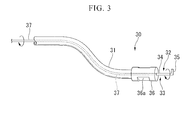
- Fig. 3 is a schematic diagram showing the treatment tool 30.
- the treatment tool 30 is a medical device disposed in the inside of a body.
- the treatment tool 30 has a flexible tube part 31 having flexibility, a treatment part 32, a conducting wire 37, and a plug (not shown).
- the treatment part 32 is disposed at a first end of the flexible tube part 31.
- the conducting wire 37 energizes the treatment part 32 with a high frequency current.
- the plug is connected to the conducting wire 37 disposed at a second end of the flexible tube part 31.
- the flexible tube part 31 is a tubular member flexibly formed of a resin and is a long member inserted into the treatment tool channel 16.
- the treatment part 32 has a hook-shaped electrode 33, the ring part 36 (a part to be held, a part to be gripped, a restriction part) provided at the distal end of the flexible tube part 31, and is provided in order to perform treatment for a site to be treated.
- the treatment part 32 can incise a biological tissue.
- the hook-shaped electrode 33 is a fine line-shaped electrode having a shaft portion 34 extending concentrically with the conducting wire 37, and a hook portion 35 with a protruding end having a shape bent with respect to the shaft portion 34 at 90°.
- the ring part 36 is provided at an outer peripheral side of the shaft portion 34 in the hook-shaped electrode 33, and has a pair of grooves 36a.
- the grooves 36a formed in the ring part 36 are configured to be fitted to the grip members 27.
- the ring part 36 is made of a material with high biocompatibility.
- a metallic ring part 36 stainless steel, a nickel-titanium alloy, a cobalt-chrome-based alloy, pure titanium, a titanium alloy, and a magnesium alloy may be employed.
- PGA, PLA, PDS, TMC, poly ⁇ -caprolacton, and a copolymer thereof may be employed.
- the ring part 36 made of a nonbioabsorbable resin, nylon, polyester, polypropylene, polybutester, a fluorine resin or the like may be employed.
- the ring part 36 has sufficient strength or flexibility so as not to be easily broken such that fragments generated when the ring part 36 is cut or divided by the gripping of the grip members 27 are prevented from remaining in the inside of a body.
- the ring part 36 is made of a material with high biocompatibility, such that painful of a patient is restricted to a minimum level even though the fragments of the ring part 36 remain inside of the body.
- the conducting wire 37 is also used as a wire for advancing, retracting, and rotating the hook-shaped electrode 33, in addition to the energizing of a high frequency current.
- the conducting wire 37 is advanced and retracted along its own central axial line, it is possible to adjust the protruding length of the hook-shaped electrode 33 from the flexible tube part 31.
- the conducting wire 37 is rotated around its own central axial line, the hook-shaped electrode 33 is rotated around the central axial line of the flexible tube part 31, so that it is possible to change the direction of the hook-shaped electrode 33.
- the treatment tool 30 of the present embodiment is a medical device capable of incising a biological tissue by connecting a high frequency power supply apparatus to the treatment tool 30 and applying a high frequency current to the biological tissue through the hook-shaped electrode 33.
- the structure of the treatment tool 30 is not limited to the medical device using a high frequency current, and a treatment tool having a well-known structure may be appropriately selected and employed as long as it has dimensions by which it is insertable into the treatment tool channel 16.
- a snare, a basket, grip forceps, a needle holder, a suture instrument, a test probe or the like for an endoscope may be employed.
- FIG. 4 is a diagram showing the operation of the medical system 1 when used.
- the external tube 11 of the endoscope device 10 for treatment is inserted into the inside of a body, and the observation device 15 is further inserted into the endoscope channel 12, so that the imaging mechanism 13 is guided up to the vicinity of a site to be treated.
- the bending operation of the external tube 11, for example, is performed by the master arm 3 by switching a mode of the master arm 3 to a mode of operating the external tube 11 through a foot switch provided on the master manipulator 2.
- the treatment tool 30 is inserted into the treatment tool channel 16 of the external tube 11. Then, the treatment part 32 of the treatment tool 30 is gripped using the grip part 26 provided on the holding tool 20 by operating the grip part provided on the master arm 3. In the present embodiment, any of the two holding tools 20 can grip the treatment part 32.
- the treatment part 32 can be held by the grip member 27.
- the advance and retraction movement of the ring part 36 to/from the grip member 27 is restricted.
- an assistant (not shown) in the vicinity of a patient rotates the conducting wire 37 around the central axial line of the conducting wire 37, so that it is possible to freely change the direction of the hook-shaped electrode 33.
- the treatment part 32 is gripped by the other one of the holding tools 20, so that the treatment part 32 can be used.
- a part of the treatment part 32 other than the ring part 36 or the flexible tube part 31 is gripped using the grip part 26 of the other one of the holding tools 20.
- the one of the holding tools 20 is detached from the ring part 36, and is shifted to a part of the treatment part 32 other than the ring part 36 or the flexible tube part 31.
- the ring part 36 is surrounded by the other one of the holding tools 20. Consequently, the switching of the treatment part 32 and orientation change for a target part of the treatment tool 30 are possible without dropping the treatment part 32.
- a holding tool 20 not gripping the treatment part 32 can be used in order to support a tissue X in the vicinity of the site to be treated.
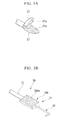
- FIG. 5A and Fig. 5B are schematic diagrams showing the structure of the present modification.
- a part 36A to be gripped having a frictional surface 36Aa with a concave and convex portion is provided. Furthermore, the grip member 27 is provided with a concave and convex portion 27a so as to frictionally engage with the frictional surface 36Aa.
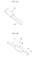
- FIG. 6A and Fig. 6B are schematic diagrams showing the structure of the present modification.
- the treatment part 32 has a body 38 to be absorbed (a part to be held) including a magnetic body, instead of the ring part 36, and the holding tool 20 has an absorbing body 39 having an electromagnet, instead of the grip part 26.
- the body 38 to be absorbed can be absorbed by the absorbing body 39.
- the body 38 to be absorbed can be absorbed by the absorbing body 39.
- Fig. 7 is a schematic diagram showing the structure of the present modification.
- the treatment part 32 has a body 40 to be absorbed (a part to be held) including an elastic member such as rubber, instead of the ring part 36, and the holding tool 20 has an absorbing pad 41, instead of the grip part 26.
- the absorbing pad 41 is provided with a suction pipeline 42 and decompresses the inside while abutting the body 40 to be absorbed, so that the body 40 to be absorbed is absorbed by a sucker.
- Fig. 8 is a schematic diagram showing the structure of the present modification.
- the present modification is different from the aforementioned embodiment in that a part 43 to be inserted (a part to be held) and a rod-shaped part 44 (a holding part) inserted into the part 43 to be inserted are provided as shown in Fig. 8 , instead of the ring part 36 and the grip part 26 described in the aforementioned embodiment.
- holes 43a into which the rod-shaped part 44 is inserted, are formed in the outer surface of the flexible tube part 31.
- the part 43 to be inserted and the rod-shaped part 44 engage with each other by friction or the like.
- the rod-shaped part 44 is moved, so that the treatment tool 30 having the part 43 to be inserted operates together with the rod-shaped part 44.
- the rod-shaped part may be provided in a part to be held, and the holes, into which the rod-shaped part is inserted, may be provided in a holding part.
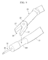
- Fig. 9 is a schematic diagram showing the structure of the present modification.
- a needle tube 45 is disposed at the distal end of the flexible tube part 31 and the inside of the flexible tube part 31 communicates with the inside of the needle tube 45. Consequently, drugs can be injected from the proximal end of the flexible tube part 31 and can be discharged from the distal end of the needle tube 45.
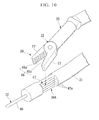
- Fig. 10 is a schematic diagram showing the structure of the present modification.
- the grip part 26 and the part 36A to be gripped have concave-convex shapes 46 and 47 that engage with each other.
- the concave-convex shape 46 formed in the grip part 26 is provided on each grip member 27, and has a plurality of projection-stripe portions 46a extending in parallel to one another.
- the concave-convex shape 47 formed in the part 36A to be gripped has a plurality of projection-stripe portions 47a extending in parallel to one another on the outer surface of the part 36A to be gripped.
- the projection-stripe portions 47a extend in the longitudinal axial direction of the flexible tube part 31 (the treatment tool 30).
- the plurality of projection-stripe portions 47a extend in the longitudinal axial direction of the flexible tube part 31 (the treatment tool 30); however, the plurality of projection-stripe portions 47a may extend in a direction (an oblique direction) crossing the longitudinal axial direction of the flexible tube part 31 (the treatment tool 30) when viewed from the side of the flexible tube part 31.
- a straight needle-shaped electrode 48 provided at the distal end of the flexible tube part 31 is provided as the treatment part 32.
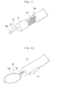
- Fig. 11 is a schematic diagram showing the structure of the present modification.
- the part 36A to be gripped has a plurality of conical-shaped portions 49 having apexes capable of coming in contact with the grip part 26.
- a rod-shaped electrode 50 provided with a conical-shaped distal end portion 50a having a diameter that gradually decreases toward the distal end side is provided on the distal end of the flexible tube part 31.
- the grip surface of the grip part 26 be provided with a plurality of conical-shaped portions that engage with the plurality of conical-shaped portions 49.
- Fig. 12 is a schematic diagram showing the structure of the present modification.
- a tab 51 (a part to be held) protruding outward in the diameter direction of the flexible tube part 31 is provided.
- the tab 51 is gripped by the grip part 26 similarly to the part 36A to be gripped.
- the length in the diameter direction of the flexible tube part 31 including the tab 51 is smaller than the inner diameter of the treatment tool channel 16.
- a rod-shaped electrode 52 with a snare loop 52a provided on a distal end thereof is provided on the distal end of the flexible tube part 31.
- Fig. 13 is a schematic diagram showing the structure of a modification 9 of the aforementioned embodiment.
- Fig. 14A is a schematic plan view showing an effect of a medical system in the present modification
- Fig. 14B is a schematic side view showing the effect of the medical system in the present modification.
- Fig. 15A is a schematic side view showing the effect of the medical system in the present modification
- Fig. 15B is a schematic plan view showing the effect of the medical system in the present modification.
- protrusions 53 and 54 are provided instead of the part 36A to be gripped.
- protrusions 53 and 54 are provided at one of two places which face to the diameter direction of the flexible tube part 31.
- holes 55 and 56 into which at least parts of the protrusions 53 and 54 are inserted, respectively, are formed in the grip members 27 of the grip part 26.
- the length of the flexible tube part 31 including the protrusions 53 and 54 in the diameter direction is smaller than the inner diameter of the treatment tool channel 16.
- the treatment part 32 in the state in which the protrusions 53 and 54 are inserted into the holes 55 and 56 formed in the grip members 27, the treatment part 32 can be rotated with respect to the grip part 26 by employing the central axial lines of the protrusions 53 and 54 as rotating centers as shown in Fig. 14A . At this time, the treatment part 32 is supported by each grip member 27 so as not to translate in the directions of the central axial lines of the protrusions 53 and 54 as shown in Fig. 14B . Furthermore, as shown in Fig. 15A and Fig. 15B , when the outer surface of the flexible tube part 31 is surrounded by each grip member 27, the direction of the treatment part 32 can be positioned in a desired direction.
- the structure in which the part to be held is held by the holding part by fitting, friction, magnetic force, or absorption has been described; however, the part to be held may be a marking for simply indicating a position at which the treatment part can be preferably held. Such a marking may be configured to inform an operator of desired angle and position at which the treatment part, in which the direction of the hook-shaped electrode when used has been decided, is held.
- the master arm 3 in the master manipulator 2 of the master-slave type system has been described as an example; however, the present invention is not limited thereto. Even in a structure in which the operation part is directly provided at the distal end of the endoscope device 10 for treatment, the same effects of the present invention are achieved.
- the structure in which the holding tool is mounted at the distal end of the external tube 11 has been described as an example; however, the holding tool is not limited thereto.
- a structure in which the holding tool is inserted into a channel formed in the external tube 11 may also be employed. In this case, a portion exposed by the distal end of the external tube 11 is an arm part.
- a treatment tool that is entirely introduced into the inside of a body and used may also be employed.
- a knife, a retractor or the like disposed in the inside of the body is employed as the treatment tool, and can be held by the holding tool for use.
- the part to be held is provided on the treatment tool itself by performing processing such as shaving of a part other than the treatment part of the treatment tool.
- the part to be held is not limited to the part to be held provided on the flexible tube part as in the aforementioned embodiment and each modification.
- a device not for diagnosis or medical cure of the human body can be introduced into the inside of the body, and can be used similarly to the aforementioned embodiment and each modification.
- the medical system and the operation method of the device such as the treatment tool it is possible to simply change the direction, position, orientation or the like of the device such as the treatment tool while maintaining the direction of the insertion part.
Landscapes
- Health & Medical Sciences (AREA)
- Life Sciences & Earth Sciences (AREA)
- Surgery (AREA)
- Engineering & Computer Science (AREA)
- Animal Behavior & Ethology (AREA)
- General Health & Medical Sciences (AREA)
- Biomedical Technology (AREA)
- Heart & Thoracic Surgery (AREA)
- Veterinary Medicine (AREA)
- Nuclear Medicine, Radiotherapy & Molecular Imaging (AREA)
- Public Health (AREA)
- Molecular Biology (AREA)
- Medical Informatics (AREA)
- Robotics (AREA)
- Cardiology (AREA)
- Radiology & Medical Imaging (AREA)
- Ophthalmology & Optometry (AREA)
- Oral & Maxillofacial Surgery (AREA)
- Pathology (AREA)
- Surgical Instruments (AREA)
- Endoscopes (AREA)
Abstract
Description
- The present invention relates to a medical system and an operation method.
- Priority is claimed on Japanese Patent Application No.
2012-189881, filed August 30, 2012 - Conventionally, a treatment tool used together with an endoscope has been known as a treatment tool for performing treatment in the inside of a body. For example, Patent Literature 1 discloses an endoscope treatment system including an endoscope provided with an insertion part inserted into the inside of the body and a treatment tool mounted in the insertion part of the endoscope.
- In the endoscope treatment system disclosed in Patent Literature 1, the treatment tool mounted in the endoscope is detachable from the endoscope and can be received in a receiving part mounted in the endoscope. Furthermore, in Patent Literature 1, forceps are provided as an example of the treatment tool.
- Japanese Patent No.
4271088 - In the endoscope treatment system disclosed in Patent Literature 1, in order to change the direction and orientation of the forceps, it is necessary to change the direction and orientation of the insertion part. Therefore, in the endoscope treatment system disclosed in Patent Literature 1, since there is a limitation in changing the direction and orientation of the insertion part in a narrow lumen, there is a limitation in the direction and orientation of disposal of the treatment tool in a target part and skill is required in operation.
- An object of the present invention is to provide a medical system capable of simply changing the direction, position, orientation or the like of a device such as a treatment tool while maintaining the direction of an insertion part, and an operation method of the device such as a treatment tool.
- A medical system according to a first aspect of the present invention includes an insertion part inserted into an inside of a body, an arm part provided on the insertion part and capable of moving with respect to the insertion part, a device disposed in the inside of the body, a holding part provided on the arm part and holding the device, and a part to be held provided on the device and held by the holding part.
- According to a second aspect of the present invention, in the medical system according to the first aspect, at least one of the holding part and the part to be held may have a restriction part that restricts movement of the device.
- According to a third aspect of the present invention, in the medical system according to the first aspect or the second aspect, the holding part may have a grip part that grips the part to be held, and the part to be held may have a part to be gripped capable of engaging with the grip part.
- According to a fourth aspect of the present invention, in the medical system according to any one of the first aspect to the third aspect, the holding part and the part to be held may have concave-convex shapes engaging with each other.
- According to a fifth aspect of the present invention, in the medical system according to any one of the first aspect to the fourth aspect, the holding part and the part to be held may engage with each other through frictional force.
- According to a sixth aspect of the present invention, in the medical system according to any one of the first aspect to the fifth aspect, a rod-shaped part may be provided on one of the holding part and the part to be held, and a hole to which the rod-shaped part is fitted may be formed in a remaining one of the holding part and the part to be held.
- According to a seventh aspect of the present invention, in the medical system according to any one of the first aspect to the sixth aspect, the part to be held may have a plurality of projection-stripe portions, and the plurality of projection-stripe portions may extend in parallel to one another in a longitudinal axial direction of the device.
- According to an eighth aspect of the present invention, in the medical system according to any one of the first aspect to the seventh aspect, the part to be held may have a plurality of conical-shaped portions having apexes capable of coming in contact with the holding part.
- According to a ninth aspect of the present invention, in the medical system according to any one of the first aspect to the eighth aspect, the insertion part may have an external tube and a device channel formed in the external tube, and the device may have a flexible tube part insertable into the device channel.
- According to a tenth aspect of the present invention, in an operation method of a device disposed in an inside of a body, a part of the device is held using a holding part provided on an arm part that is the body provided separately from the device and has at least one degree of freedom, and the arm part is moved, so that the device held by the holding part is moved together with the arm part.
- According to the medical system and the operation method of a device disposed in the inside of a body, it is possible to simply change the direction, position, orientation or the like of the device such as a treatment tool while maintaining the direction of the insertion part.
-
-
Fig. 1 is an overall view of a medical system according to one embodiment of the present invention. -
Fig. 2 is a perspective view showing the structure of a part of a medical system according to one embodiment of the present invention. -
Fig. 3 is a schematic diagram showing a treatment tool in a medical system according to one embodiment of the present invention. -
Fig. 4 is a diagram showing the operation of a medical system when used according to one embodiment of the present invention. -
Fig. 5A is a schematic diagram showing the structure of a modification 1 of one embodiment of the present invention. -
Fig. 5B is a schematic diagram showing the structure of a modification 1 of one embodiment of the present invention. -
Fig. 6A is a schematic diagram showing the structure of amodification 2 of one embodiment of the present invention. -
Fig. 6B is a schematic diagram showing the structure of amodification 2 of one embodiment of the present invention. -
Fig. 7 is a schematic diagram showing the structure of amodification 3 of one embodiment of the present invention. -
Fig. 8 is a schematic diagram showing the structure of amodification 4 of one embodiment of the present invention. -
Fig. 9 is a schematic diagram showing the structure of amodification 5 of one embodiment of the present invention. -
Fig. 10 is a schematic diagram showing the structure of amodification 6 of one embodiment of the present invention. -
Fig. 11 is a schematic diagram showing the structure of amodification 7 of one embodiment of the present invention. -
Fig. 12 is a schematic diagram showing the structure of amodification 8 of one embodiment of the present invention. -
Fig. 13 is a schematic diagram showing the structure of a modification 9 of one embodiment of the present invention. -
Fig. 14A is a plan view showing an effect in a modification 9 of one embodiment of the present invention. -
Fig. 14B is a side view showing an effect in a modification 9 of one embodiment of the present invention. -
Fig. 15A is a plan view showing an effect in a modification 9 of one embodiment of the present invention. -
Fig. 15B is a side view showing an effect in a modification 9 of one embodiment of the present invention. - A medical system of one embodiment of the present invention will be described below.
Fig. 1 is an overall view of a medical system of the present embodiment.Fig. 2 is a perspective view showing the structure of a part of the medical system. - As shown in
Fig. 1 andFig. 2 , a medical system 1 of the present embodiment is a master-slave type system including amaster manipulator 2 operated by an operator Op for treatment, and aslave manipulator 6 provided with anendoscope device 10 for treatment. - The
master manipulator 2 includesmaster arms 3, adisplay part 4, and acontrol part 5. Themaster arms 3 are operated by the operator Op. Thedisplay part 4 displays video or the like captured using theendoscope device 10 for treatment. Thecontrol part 5 generates an operation command for operating theslave manipulator 6 on the basis of the operation of themaster arms 3. - In the present embodiment, the
master arms 3 are operation parts provided in order to operate holding tools 20 (which will be described later) mounted in theendoscope device 10 for treatment. Although not shown in detail, themaster manipulator 2 has themaster arms 3 corresponding to the right hand and the left hand of the operator Op. Each of themaster arms 3 has a multiple joint structure used to operate ajoint part 22 of the holdingtool 20 having at least one degree of freedom, which will be described later. A grip part (not shown) for operating agrip part 26 of the holdingtool 20, which will be described later, is provided at an end portion of each of themaster arms 3 positioned at the operator Op side. - The
display part 4 is a device on which the video of a site to be treated, which is captured by an observation device 15 (which will be described later) mounted in theendoscope device 10 for treatment, is displayed. On thedisplay part 4, the video of the holdingtool 20 and the video of atreatment tool 30, which will be described later, are also displayed together with the video of the site to be treated. - The
slave manipulator 6 has a placement table 7 on which a patient is placed, a multiple-joint robot 8 disposed in the vicinity of the placement table 7, theendoscope device 10 for treatment mounted in the multiple-joint robot 8, the holding tool 20 (an arm part), and thetreatment tool 30. Thetreatment tool 30 is an example of a device disposed inside of a body. The multiple-joint robot 8 operates according to the operation command sent from themaster manipulator 2. - As shown in
Fig. 2 , theendoscope device 10 for treatment has an external tube (an insertion part) and anendoscope channel 12, and the holdingtool 20 is mounted at a distal end of theexternal tube 11. - The
external tube 11 of theendoscope device 10 for treatment is a long member that is inserted into the inside of a patient's body. Theexternal tube 11 may be curved by a well-knowncurved mechanism 11A and can direct the holdingtool 20 in a desired direction in the inside of the body. Furthermore, theexternal tube 11 is provided with atreatment tool channel 16 into which thetreatment tool 30 is inserted. - Furthermore, the
observation device 15 having animaging mechanism 13 and anillumination mechanism 14 is inserted into theendoscope channel 12 provided in theexternal tube 11. - The
endoscope channel 12 is provided in theexternal tube 11 so as to be opened at the distal end of theexternal tube 11. - The
observation device 15 is a device for observing a site to be treated using theimaging mechanism 13 and theillumination mechanism 14. Theobservation device 15 may also have a curved mechanism (not shown) for directing theimaging mechanism 13 and theillumination mechanism 14 in a desired direction. Furthermore, as theobservation device 15, an endoscope having a well-known structure may also be appropriately selected and employed. - The holding
tool 20 has thejoint part 22 that is curved by the operation of themaster arm 3, and the grip part 26 (a holding part) mounted in thejoint part 22. In the holdingtool 20, a curvable structure is not limited to the joint structure based on a combination of long tubular parts as shown inFig. 2 andFig. 4 . For example, in the holdingtool 20, as the curvable structure, a joint structure in which a plurality of curved pieces are concatenated to one another so as to rotate may also be employed. - The
grip part 26 is a member for holdinggrooves 36a of aring part 36, which will be described later, with thegrooves 36a interposed therebetween, and has a pair ofgrip members 27 entering thegrooves 36a of thering part 36. In thegrip part 26, the pair ofgrip members 27 are opened and closed by the operation of the aforementioned operation part. Furthermore, thegrip part 26 is further provided with a two-axis joint for bending thegrip part 26 at the distal end of thejoint part 22. -
Fig. 3 is a schematic diagram showing thetreatment tool 30. As shown inFig. 3 , thetreatment tool 30 is a medical device disposed in the inside of a body. Thetreatment tool 30 has aflexible tube part 31 having flexibility, atreatment part 32, aconducting wire 37, and a plug (not shown). Thetreatment part 32 is disposed at a first end of theflexible tube part 31. Theconducting wire 37 energizes thetreatment part 32 with a high frequency current. The plug is connected to theconducting wire 37 disposed at a second end of theflexible tube part 31. - The
flexible tube part 31 is a tubular member flexibly formed of a resin and is a long member inserted into thetreatment tool channel 16. - The
treatment part 32 has a hook-shapedelectrode 33, the ring part 36 (a part to be held, a part to be gripped, a restriction part) provided at the distal end of theflexible tube part 31, and is provided in order to perform treatment for a site to be treated. In the present embodiment, thetreatment part 32 can incise a biological tissue. - The hook-shaped
electrode 33 is a fine line-shaped electrode having ashaft portion 34 extending concentrically with theconducting wire 37, and ahook portion 35 with a protruding end having a shape bent with respect to theshaft portion 34 at 90°. - The
ring part 36 is provided at an outer peripheral side of theshaft portion 34 in the hook-shapedelectrode 33, and has a pair ofgrooves 36a. Thegrooves 36a formed in thering part 36 are configured to be fitted to thegrip members 27. Thering part 36 is made of a material with high biocompatibility. For example, as ametallic ring part 36, stainless steel, a nickel-titanium alloy, a cobalt-chrome-based alloy, pure titanium, a titanium alloy, and a magnesium alloy may be employed. Furthermore, as a bioabsorbableresin ring part 36, PGA, PLA, PDS, TMC, poly ε-caprolacton, and a copolymer thereof may be employed. Furthermore, as thering part 36 made of a nonbioabsorbable resin, nylon, polyester, polypropylene, polybutester, a fluorine resin or the like may be employed. Thering part 36 has sufficient strength or flexibility so as not to be easily broken such that fragments generated when thering part 36 is cut or divided by the gripping of thegrip members 27 are prevented from remaining in the inside of a body. Thering part 36 is made of a material with high biocompatibility, such that painful of a patient is restricted to a minimum level even though the fragments of thering part 36 remain inside of the body. - The
conducting wire 37 is also used as a wire for advancing, retracting, and rotating the hook-shapedelectrode 33, in addition to the energizing of a high frequency current. When theconducting wire 37 is advanced and retracted along its own central axial line, it is possible to adjust the protruding length of the hook-shapedelectrode 33 from theflexible tube part 31. When theconducting wire 37 is rotated around its own central axial line, the hook-shapedelectrode 33 is rotated around the central axial line of theflexible tube part 31, so that it is possible to change the direction of the hook-shapedelectrode 33. - The
treatment tool 30 of the present embodiment is a medical device capable of incising a biological tissue by connecting a high frequency power supply apparatus to thetreatment tool 30 and applying a high frequency current to the biological tissue through the hook-shapedelectrode 33. - The structure of the
treatment tool 30 is not limited to the medical device using a high frequency current, and a treatment tool having a well-known structure may be appropriately selected and employed as long as it has dimensions by which it is insertable into thetreatment tool channel 16. For example, as thetreatment tool 30, a snare, a basket, grip forceps, a needle holder, a suture instrument, a test probe or the like for an endoscope may be employed. - Next, the operation and effect of the medical system 1 when used will be described.
Fig. 4 is a diagram showing the operation of the medical system 1 when used. - At the time of use of the medical system 1, the
external tube 11 of theendoscope device 10 for treatment is inserted into the inside of a body, and theobservation device 15 is further inserted into theendoscope channel 12, so that theimaging mechanism 13 is guided up to the vicinity of a site to be treated. The bending operation of theexternal tube 11, for example, is performed by themaster arm 3 by switching a mode of themaster arm 3 to a mode of operating theexternal tube 11 through a foot switch provided on themaster manipulator 2. - Furthermore, when it is necessary to treat the site to be treated, the
treatment tool 30 is inserted into thetreatment tool channel 16 of theexternal tube 11. Then, thetreatment part 32 of thetreatment tool 30 is gripped using thegrip part 26 provided on the holdingtool 20 by operating the grip part provided on themaster arm 3. In the present embodiment, any of the twoholding tools 20 can grip thetreatment part 32. - When the
grip member 27 provided on thegrip part 26 of the holdingtool 20 is opened, fitted to thegrooves 36a of thering part 36, and closed, thetreatment part 32 can be held by thegrip member 27. At this time, the advance and retraction movement of thering part 36 to/from thegrip member 27 is restricted. Thus, for example, an assistant (not shown) in the vicinity of a patient rotates theconducting wire 37 around the central axial line of theconducting wire 37, so that it is possible to freely change the direction of the hook-shapedelectrode 33. - Furthermore, in the case of using the
treatment part 32 outside of a movable range of one of theholding tools 20, thetreatment part 32 is gripped by the other one of theholding tools 20, so that thetreatment part 32 can be used. In the case of switching thetreatment part 32 between the twoholding tools 20, for example, in the state in which thering part 36 is gripped in the one of theholding tools 20, a part of thetreatment part 32 other than thering part 36 or theflexible tube part 31 is gripped using thegrip part 26 of the other one of theholding tools 20. Thereafter, the one of theholding tools 20 is detached from thering part 36, and is shifted to a part of thetreatment part 32 other than thering part 36 or theflexible tube part 31. Moreover, thering part 36 is surrounded by the other one of theholding tools 20. Consequently, the switching of thetreatment part 32 and orientation change for a target part of thetreatment tool 30 are possible without dropping thetreatment part 32. - Furthermore, at the time of the use of the medical system 1, between the two
holding tools 20, a holdingtool 20 not gripping thetreatment part 32 can be used in order to support a tissue X in the vicinity of the site to be treated. - As described above, according to the medical system 1 of the present embodiment, it is possible to simply change the direction, position, orientation or the like of the
treatment tool 30 while maintaining the direction of theexternal tube 11. - Furthermore, in the state in which the movement of the advance and retraction direction of the
treatment tool 30 is restricted by the holdingtool 20, it is possible to rotate thetreatment part 32 by employing the central axial line of theflexible tube part 31 as a rotation center. Consequently, it is possible to adjust the direction of thehook portion 35 to be preferably directed to an object to be treated, and to treat a tissue. - Next, a modification 1 of the aforementioned embodiment will be described.
Fig. 5A and Fig. 5B are schematic diagrams showing the structure of the present modification. - As shown in
Fig. 5A and Fig. 5B , in the present modification, instead of thering part 36, apart 36A to be gripped having a frictional surface 36Aa with a concave and convex portion is provided. Furthermore, thegrip member 27 is provided with a concave andconvex portion 27a so as to frictionally engage with the frictional surface 36Aa. - Even in such a structure, the same effects as those of the aforementioned embodiment are achieved.
- Next, a
modification 2 of the aforementioned embodiment will be described.Fig. 6A and Fig. 6B are schematic diagrams showing the structure of the present modification. - As shown in
Fig. 6A and Fig. 6B , in the present modification, thetreatment part 32 has abody 38 to be absorbed (a part to be held) including a magnetic body, instead of thering part 36, and the holdingtool 20 has an absorbingbody 39 having an electromagnet, instead of thegrip part 26. - In the present modification, while the electromagnet is being energized, the
body 38 to be absorbed can be absorbed by the absorbingbody 39. In this case, as compared to the case in which theaforementioned grip part 26 is employed, it is not necessary for an operator to continuously apply force for closing thegrip member 27, and it is possible to hold thetreatment part 32 through the on-off control of power for the electromagnet. - Next, a
modification 3 of the aforementioned embodiment will be described.Fig. 7 is a schematic diagram showing the structure of the present modification. - As shown in
Fig. 7 , in the present modification, thetreatment part 32 has abody 40 to be absorbed (a part to be held) including an elastic member such as rubber, instead of thering part 36, and the holdingtool 20 has an absorbingpad 41, instead of thegrip part 26. - The absorbing
pad 41 is provided with asuction pipeline 42 and decompresses the inside while abutting thebody 40 to be absorbed, so that thebody 40 to be absorbed is absorbed by a sucker. - Even in such a structure, the same effects as those of the aforementioned embodiment are achieved.
- Next, a
modification 4 of the aforementioned embodiment will be described.Fig. 8 is a schematic diagram showing the structure of the present modification. - The present modification is different from the aforementioned embodiment in that a
part 43 to be inserted (a part to be held) and a rod-shaped part 44 (a holding part) inserted into thepart 43 to be inserted are provided as shown inFig. 8 , instead of thering part 36 and thegrip part 26 described in the aforementioned embodiment. In thepart 43 to be inserted,holes 43a, into which the rod-shapedpart 44 is inserted, are formed in the outer surface of theflexible tube part 31. In the state in which the rod-shapedpart 44 is inserted into thepart 43 to be inserted, thepart 43 to be inserted and the rod-shapedpart 44 engage with each other by friction or the like. In the state in which the rod-shapedpart 44 is inserted into thepart 43 to be inserted, the rod-shapedpart 44 is moved, so that thetreatment tool 30 having thepart 43 to be inserted operates together with the rod-shapedpart 44. - In addition, instead of the
ring part 36 and thegrip part 26 described in the aforementioned embodiment, the rod-shaped part may be provided in a part to be held, and the holes, into which the rod-shaped part is inserted, may be provided in a holding part. - Even in such a structure, the same effects as those of the aforementioned embodiment are achieved.
- Next, a
modification 5 of the aforementioned embodiment will be described.Fig. 9 is a schematic diagram showing the structure of the present modification. - As shown in
Fig. 9 , in the present modification, aneedle tube 45 is disposed at the distal end of theflexible tube part 31 and the inside of theflexible tube part 31 communicates with the inside of theneedle tube 45. Consequently, drugs can be injected from the proximal end of theflexible tube part 31 and can be discharged from the distal end of theneedle tube 45. - Even in the structure of the present modification, the same effects as those of the aforementioned embodiment are achieved.
- Next, a
modification 6 of the aforementioned embodiment will be described.Fig. 10 is a schematic diagram showing the structure of the present modification. - As shown in
Fig. 10 , in the present modification, thegrip part 26 and thepart 36A to be gripped have concave-convex shapes - The concave-
convex shape 46 formed in thegrip part 26 is provided on eachgrip member 27, and has a plurality of projection-stripe portions 46a extending in parallel to one another. - The concave-
convex shape 47 formed in thepart 36A to be gripped has a plurality of projection-stripe portions 47a extending in parallel to one another on the outer surface of thepart 36A to be gripped. The projection-stripe portions 47a extend in the longitudinal axial direction of the flexible tube part 31 (the treatment tool 30). - In addition, in the present modification, as shown in
Fig. 10 , the plurality of projection-stripe portions 47a extend in the longitudinal axial direction of the flexible tube part 31 (the treatment tool 30); however, the plurality of projection-stripe portions 47a may extend in a direction (an oblique direction) crossing the longitudinal axial direction of the flexible tube part 31 (the treatment tool 30) when viewed from the side of theflexible tube part 31. - Furthermore, in the present modification, a straight needle-shaped
electrode 48 provided at the distal end of theflexible tube part 31 is provided as thetreatment part 32. - Even in the structure of the present modification, the same effects as those of the aforementioned embodiment are achieved.
- Next, a
modification 7 of the aforementioned embodiment will be described.Fig. 11 is a schematic diagram showing the structure of the present modification. - As shown in
Fig. 11 , in the present modification, thepart 36A to be gripped has a plurality of conical-shapedportions 49 having apexes capable of coming in contact with thegrip part 26. - Furthermore, in the present modification, as the
treatment part 32, a rod-shapedelectrode 50 provided with a conical-shapeddistal end portion 50a having a diameter that gradually decreases toward the distal end side is provided on the distal end of theflexible tube part 31. - Even in such a structure, the same effects as those of the aforementioned embodiment are achieved.
- In addition, it is preferable that the grip surface of the
grip part 26 be provided with a plurality of conical-shaped portions that engage with the plurality of conical-shapedportions 49. - Next, a
modification 8 of the aforementioned embodiment will be described.Fig. 12 is a schematic diagram showing the structure of the present modification. - As shown in
Fig. 12 , in the present modification, instead of thepart 36A to be gripped, a tab 51 (a part to be held) protruding outward in the diameter direction of theflexible tube part 31 is provided. Thetab 51 is gripped by thegrip part 26 similarly to thepart 36A to be gripped. In this case, the length in the diameter direction of theflexible tube part 31 including thetab 51 is smaller than the inner diameter of thetreatment tool channel 16. - Furthermore, in the present modification, as the
treatment part 32, a rod-shapedelectrode 52 with asnare loop 52a provided on a distal end thereof is provided on the distal end of theflexible tube part 31. - Even in such a structure, the same effects as those of the aforementioned embodiment are achieved.
-
Fig. 13 is a schematic diagram showing the structure of a modification 9 of the aforementioned embodiment.Fig. 14A is a schematic plan view showing an effect of a medical system in the present modification, andFig. 14B is a schematic side view showing the effect of the medical system in the present modification.Fig. 15A is a schematic side view showing the effect of the medical system in the present modification, andFig. 15B is a schematic plan view showing the effect of the medical system in the present modification. - As shown in
Fig. 13 , in the present modification, instead of thepart 36A to be gripped,protrusions 53 and 54 (parts to be held) protruding outward in the diameter direction of theflexible tube part 31 are provided. Each of theprotrusions flexible tube part 31. - Furthermore, holes 55 and 56, into which at least parts of the
protrusions grip members 27 of thegrip part 26. In this case, the length of theflexible tube part 31 including theprotrusions treatment tool channel 16. - In the present modification, in the state in which the
protrusions holes grip members 27, thetreatment part 32 can be rotated with respect to thegrip part 26 by employing the central axial lines of theprotrusions Fig. 14A . At this time, thetreatment part 32 is supported by eachgrip member 27 so as not to translate in the directions of the central axial lines of theprotrusions Fig. 14B . Furthermore, as shown inFig. 15A and Fig. 15B , when the outer surface of theflexible tube part 31 is surrounded by eachgrip member 27, the direction of thetreatment part 32 can be positioned in a desired direction. - So far, the embodiment of the present invention has been described in detail with reference to the accompanying drawings. However, detailed configurations are not limited to the embodiment. For example, a design change and the like within the range without departing from the scope of the present invention are also included.
- For example, in the present embodiment, the structure in which the part to be held is held by the holding part by fitting, friction, magnetic force, or absorption has been described; however, the part to be held may be a marking for simply indicating a position at which the treatment part can be preferably held. Such a marking may be configured to inform an operator of desired angle and position at which the treatment part, in which the direction of the hook-shaped electrode when used has been decided, is held.
- Furthermore, in the present embodiment, as the operation part, the
master arm 3 in themaster manipulator 2 of the master-slave type system has been described as an example; however, the present invention is not limited thereto. Even in a structure in which the operation part is directly provided at the distal end of theendoscope device 10 for treatment, the same effects of the present invention are achieved. - Furthermore, in the present embodiment, the structure in which the holding tool is mounted at the distal end of the
external tube 11 has been described as an example; however, the holding tool is not limited thereto. For example, a structure in which the holding tool is inserted into a channel formed in theexternal tube 11 may also be employed. In this case, a portion exposed by the distal end of theexternal tube 11 is an arm part. - Furthermore, as the treatment tool, a treatment tool that is entirely introduced into the inside of a body and used may also be employed. For example, a knife, a retractor or the like disposed in the inside of the body is employed as the treatment tool, and can be held by the holding tool for use. In this case, the part to be held is provided on the treatment tool itself by performing processing such as shaving of a part other than the treatment part of the treatment tool. As described above, the part to be held is not limited to the part to be held provided on the flexible tube part as in the aforementioned embodiment and each modification.
- Furthermore, instead of the treatment tool, a device not for diagnosis or medical cure of the human body can be introduced into the inside of the body, and can be used similarly to the aforementioned embodiment and each modification.
- Furthermore, the elements in the aforementioned embodiment and each modification can be appropriately combined with one another.
- According to the medical system and the operation method of the device such as the treatment tool, it is possible to simply change the direction, position, orientation or the like of the device such as the treatment tool while maintaining the direction of the insertion part.
-
- 1
- Medical system
- 3
- Master arm
- 10
- Endoscope device for treatment
- 11
- External tube
- 12
- Endoscope channel
- 13
- Imaging mechanism
- 14
- Illumination mechanism
- 15
- Observation device
- 16
- Treatment tool channel (Device channel)
- 20
- Holding tool
- 21
- Tube
- 22
- Joint part
- 26
- Grip part
- 27
- Grip member
- 27a
- Concave and convex portion
- 30
- Treatment tool
- 31
- Flexible tube part
- 32
- Treatment part
- 33
- Hook-shaped electrode
- 34
- Shaft portion
- 35
- Hook portion
- 36
- Ring part
- 36a
- Groove
- 36A
- Part to be gripped
- 36Aa
- Frictional surface
- 37
- Wire
- 38
- Body to be absorbed
- 39
- Absorbing body
- 40
- Body to be absorbed
- 41
- Pad
- 42
- Suction pipeline
- 43
- Part to be inserted
- 43a
- Hole
- 44
- Rod-shaped part
- 45
- Needle tube
- 46
- Concave-convex shape
- 46a
- Projection stripe
- 47
- Concave-convex shape
- 47a
- Projection stripe
- 48
- Needle-shaped electrode
- 49
- Conical-shaped portion
- 50
- Rod-shaped electrode
- 50a
- Distal end portion
- 51
- Tab
- 52
- Rod-shaped electrode
- 52a
- Snare loop
- 53, 54
- Protrusion
- 55, 56
- Hole
Claims (10)
- A medical system comprising:an insertion part inserted into an inside of a body;an arm part provided on the insertion part and capable of moving with respect to the insertion part;a device disposed in the inside of the body;a holding part provided on the arm part and holding the device; anda part to be held provided on the device and held by the holding part.
- The medical system according to claim 1, wherein at least one of the holding part and the part to be held has a restriction part that restricts movement of the device.
- The medical system according to claim 1 or 2, wherein the holding part has a grip part that grips the part to be held, and the part to be held has a part to be gripped capable of engaging with the grip part.
- The medical system according to any one of claims 1 to 3, wherein the holding part and the part to be held have concave-convex shapes engaging with each other.
- The medical system according to any one of claims 1 to 4, wherein the holding part and the part to be held engage with each other through frictional force.
- The medical system according to any one of claims 1 to 5, wherein a rod-shaped part is provided on one of the holding part and the part to be held, and a hole to which the rod-shaped part is fitted is formed in a remaining one of the holding part and the part to be held.
- The medical system according to any one of claims 1 to 6, wherein the part to be held has a plurality of projection-stripe portions, and the plurality of projection-stripe portions extend in parallel to one another in a longitudinal axial direction of the device.
- The medical system according to any one of claims 1 to 7, wherein the part to be held has a plurality of conical-shaped portions having apexes capable of coming in contact with the holding part.
- The medical system according to any one of claims 1 to 8, wherein the insertion part has an external tube and a device channel formed in the external tube, and the device has a flexible tube part insertable into the device channel.
- An operation method of a device disposed in an inside of a body, wherein
a part of the device is held using a holding part provided on an arm part that is the body provided separately from the device and has at least one degree of freedom, and
the arm part is moved, so that the device held by the holding part is moved together with the arm part.
Applications Claiming Priority (2)
| Application Number | Priority Date | Filing Date | Title |
|---|---|---|---|
| JP2012189881A JP6140950B2 (en) | 2012-08-30 | 2012-08-30 | Medical system |
| PCT/JP2013/073274 WO2014034837A1 (en) | 2012-08-30 | 2013-08-30 | Medical system and operation method |
Publications (2)
| Publication Number | Publication Date |
|---|---|
| EP2891465A1 true EP2891465A1 (en) | 2015-07-08 |
| EP2891465A4 EP2891465A4 (en) | 2016-04-20 |
Family
ID=50183642
Family Applications (1)
| Application Number | Title | Priority Date | Filing Date |
|---|---|---|---|
| EP13832228.4A Withdrawn EP2891465A4 (en) | 2012-08-30 | 2013-08-30 | Medical system and operation method |
Country Status (5)
| Country | Link |
|---|---|
| US (1) | US20150150634A1 (en) |
| EP (1) | EP2891465A4 (en) |
| JP (1) | JP6140950B2 (en) |
| CN (1) | CN104470459B (en) |
| WO (1) | WO2014034837A1 (en) |
Families Citing this family (14)
| Publication number | Priority date | Publication date | Assignee | Title |
|---|---|---|---|---|
| US20170127911A1 (en) * | 2014-03-19 | 2017-05-11 | Endomaster Pte Ltd | Master - slave flexible robotic endoscopy system |
| US11090123B2 (en) * | 2014-04-22 | 2021-08-17 | Bio-Medical Engineering (HK) Limited | Robotic devices and systems for performing single incision procedures and natural orifice translumenal endoscopic surgical procedures, and methods of configuring robotic devices and systems |
| US11154368B2 (en) | 2014-04-22 | 2021-10-26 | Bio-Medical Engineering (HK) Limited | Port assembly for use with robotic devices and systems to perform single incision procedures and natural orifice translumenal endoscopic surgical procedures |
| CN104116526B (en) * | 2014-07-11 | 2017-05-24 | 诸暨市鹏天医疗器械有限公司 | Tool combining biopsy forceps and snare |
| US9475198B2 (en) * | 2014-12-22 | 2016-10-25 | Qualcomm Incorporated | System and method for dynamic robot manipulator selection |
| CN107438409B (en) * | 2015-01-12 | 2021-02-02 | 爱普贡公司 | Apparatus and method for transcatheter heart valve repair under a trigonectomy technique |
| US10912620B2 (en) * | 2016-01-06 | 2021-02-09 | Vanderbilt University | Snare tool manipulator system |
| US10159569B2 (en) * | 2016-04-12 | 2018-12-25 | Lars Erickson | Minimally invasive atrio-ventricular valve treatment by chordae adjustment |
| US10799358B2 (en) | 2016-04-12 | 2020-10-13 | Lars Erickson | Catheter system for selectively manipulating and connecting cardiac tissues |
| KR102414011B1 (en) | 2017-12-29 | 2022-06-27 | 더 보드 오브 리젠츠 오브 더 유니버시티 오브 텍사스 시스템 | A surgical instrument and a method of positioning an end effector with respect to a cap on the end of a sheath |
| JP7085401B2 (en) * | 2018-04-27 | 2022-06-16 | 川崎重工業株式会社 | Surgical system |
| KR102614596B1 (en) * | 2020-07-27 | 2023-12-18 | 유펙스메드 주식회사 | Multi-lumen medical dispensing device for combination of multiple treatment tools |
| US11998187B2 (en) * | 2021-09-10 | 2024-06-04 | Olympus Corporation | Suture method |
| JP7662699B2 (en) * | 2023-04-14 | 2025-04-15 | 株式会社 コスミック エム イー | Surgical Support Equipment |
Family Cites Families (22)
| Publication number | Priority date | Publication date | Assignee | Title |
|---|---|---|---|---|
| US4799483A (en) * | 1988-02-11 | 1989-01-24 | Kraff Manus C | Suturing needle with tail mounted cutting blade and method for using same |
| JPH05184535A (en) * | 1991-07-24 | 1993-07-27 | Olympus Optical Co Ltd | Multifunctional treating-implement |
| JP3518905B2 (en) * | 1994-09-26 | 2004-04-12 | オリンパス株式会社 | Intracavity ultrasound probe |
| US5813976A (en) * | 1996-04-02 | 1998-09-29 | Filipi; Charles J. | Stabilizing instrumentation for the performing of endoscopic surgical procedures |
| US5957937A (en) * | 1996-11-27 | 1999-09-28 | Yoon; Inbae | Suturing instrument with spreadable needle holder mounted for arcuate movement |
| US7637905B2 (en) * | 2003-01-15 | 2009-12-29 | Usgi Medical, Inc. | Endoluminal tool deployment system |
| JP3679674B2 (en) * | 2000-02-03 | 2005-08-03 | オリンパス株式会社 | Endoscope |
| US6755843B2 (en) * | 2000-09-29 | 2004-06-29 | Olympus Optical Co., Ltd. | Endoscopic suturing device |
| JP2003204968A (en) * | 2002-01-11 | 2003-07-22 | Olympus Optical Co Ltd | Treatment instrument |
| JP2003204967A (en) * | 2002-01-11 | 2003-07-22 | Olympus Optical Co Ltd | Treatment instrument |
| JP2003204920A (en) * | 2002-01-11 | 2003-07-22 | Olympus Optical Co Ltd | Insertion assisting tool |
| US7029435B2 (en) * | 2003-10-16 | 2006-04-18 | Granit Medical Innovation, Llc | Endoscope having multiple working segments |
| JP2005334237A (en) * | 2004-05-26 | 2005-12-08 | Olympus Corp | Endoscope apparatus |
| JP5121132B2 (en) * | 2005-11-02 | 2013-01-16 | オリンパスメディカルシステムズ株式会社 | Endoscope system and operation assist device for endoscope |
| US8021293B2 (en) * | 2006-01-13 | 2011-09-20 | Olympus Medical Systems Corp. | Medical treatment endoscope |
| US8518024B2 (en) * | 2006-04-24 | 2013-08-27 | Transenterix, Inc. | System and method for multi-instrument surgical access using a single access port |
| JP5160144B2 (en) * | 2007-05-18 | 2013-03-13 | オリンパス株式会社 | Body cavity insert fixture |
| JP5100263B2 (en) * | 2007-08-31 | 2012-12-19 | オリンパス株式会社 | Treatment instrument guide |
| US20090259105A1 (en) * | 2008-04-10 | 2009-10-15 | Miyano Hiromichi | Medical treatment system and suturing method |
| US8562513B2 (en) * | 2008-05-20 | 2013-10-22 | Olympus Medical Systems Corp. | Endoscope device |
| EP2324789B1 (en) * | 2008-11-14 | 2017-06-21 | Olympus Corporation | Medical system |
| US8398633B2 (en) * | 2009-10-30 | 2013-03-19 | Covidien Lp | Jaw roll joint |
-
2012
- 2012-08-30 JP JP2012189881A patent/JP6140950B2/en active Active
-
2013
- 2013-08-30 CN CN201380038717.9A patent/CN104470459B/en active Active
- 2013-08-30 WO PCT/JP2013/073274 patent/WO2014034837A1/en not_active Ceased
- 2013-08-30 EP EP13832228.4A patent/EP2891465A4/en not_active Withdrawn
-
2015
- 2015-02-06 US US14/615,550 patent/US20150150634A1/en not_active Abandoned
Also Published As
| Publication number | Publication date |
|---|---|
| EP2891465A4 (en) | 2016-04-20 |
| JP2014045865A (en) | 2014-03-17 |
| CN104470459B (en) | 2017-07-28 |
| WO2014034837A1 (en) | 2014-03-06 |
| US20150150634A1 (en) | 2015-06-04 |
| JP6140950B2 (en) | 2017-06-07 |
| CN104470459A (en) | 2015-03-25 |
Similar Documents
| Publication | Publication Date | Title |
|---|---|---|
| EP2891465A1 (en) | Medical system and operation method | |
| US8512227B2 (en) | Apparatus for assisting operations of medical instrument attached to endoscope | |
| US20180168715A1 (en) | Visual displays of electrical pathways | |
| EP2526993A2 (en) | Treatment tool | |
| EP2471472A1 (en) | Forceps suitable for intraperitoneal manipulations and technique of using forceps suitable for intraperitoneal manipulations | |
| CN106231983B (en) | Treatment apparatus adapter, endoscope and endoscopic system | |
| JP2006239406A (en) | Medical instrument including end effector having medical-treatment electrode | |
| EP2939618B1 (en) | Surgical instrument | |
| JP2009050697A (en) | Arthroscopic instruments | |
| JP6300801B2 (en) | Medical manipulator and method for controlling medical manipulator | |
| JP2015154895A (en) | Surgical manipulator operating device and surgical manipulator system | |
| KR20180122845A (en) | Surgical instrument equipment appropriate for mini-invasive surgery | |
| CN103826525B (en) | Process utensil and endoscope's processing system | |
| JP2015047376A (en) | Tube device with puncture function | |
| JP2015130898A (en) | operation member | |
| EP2534999B1 (en) | Endoscope-holding device and endoscopic system | |
| JP5932174B1 (en) | Endoscope system | |
| WO2005110187A1 (en) | Treatment instrument for endoscope | |
| JP5019723B2 (en) | Incision forceps | |
| EP3117756A1 (en) | Endoscope and endoscope system | |
| JP2011067650A (en) | Hood for endoscope | |
| KR100994215B1 (en) | Endoscope system | |
| JP2021122312A (en) | Medical equipment | |
| JP2006175216A (en) | Suture assisting instrument |
Legal Events
| Date | Code | Title | Description |
|---|---|---|---|
| PUAI | Public reference made under article 153(3) epc to a published international application that has entered the european phase |
Free format text: ORIGINAL CODE: 0009012 |
|
| 17P | Request for examination filed |
Effective date: 20150302 |
|
| AK | Designated contracting states |
Kind code of ref document: A1 Designated state(s): AL AT BE BG CH CY CZ DE DK EE ES FI FR GB GR HR HU IE IS IT LI LT LU LV MC MK MT NL NO PL PT RO RS SE SI SK SM TR |
|
| AX | Request for extension of the european patent |
Extension state: BA ME |
|
| DAX | Request for extension of the european patent (deleted) | ||
| RA4 | Supplementary search report drawn up and despatched (corrected) |
Effective date: 20160318 |
|
| RIC1 | Information provided on ipc code assigned before grant |
Ipc: A61B 90/00 20160101AFI20160315BHEP Ipc: A61B 1/00 20060101ALI20160315BHEP Ipc: A61B 17/28 20060101ALI20160315BHEP |
|
| RAP1 | Party data changed (applicant data changed or rights of an application transferred) |
Owner name: OLYMPUS CORPORATION |
|
| RAP1 | Party data changed (applicant data changed or rights of an application transferred) |
Owner name: OLYMPUS CORPORATION |
|
| RIN1 | Information on inventor provided before grant (corrected) |
Inventor name: ISODA, TAKUMI |
|
| GRAP | Despatch of communication of intention to grant a patent |
Free format text: ORIGINAL CODE: EPIDOSNIGR1 |
|
| STAA | Information on the status of an ep patent application or granted ep patent |
Free format text: STATUS: GRANT OF PATENT IS INTENDED |
|
| RIC1 | Information provided on ipc code assigned before grant |
Ipc: A61B 17/28 20060101ALI20200122BHEP Ipc: A61B 17/29 20060101ALI20200122BHEP Ipc: A61B 1/00 20060101ALI20200122BHEP Ipc: A61B 17/34 20060101ALI20200122BHEP Ipc: A61B 90/00 20160101AFI20200122BHEP |
|
| INTG | Intention to grant announced |
Effective date: 20200224 |
|
| STAA | Information on the status of an ep patent application or granted ep patent |
Free format text: STATUS: THE APPLICATION IS DEEMED TO BE WITHDRAWN |
|
| 18D | Application deemed to be withdrawn |
Effective date: 20200707 |