EP2891394B1 - Vibration reduction rib - Google Patents
Vibration reduction rib Download PDFInfo
- Publication number
- EP2891394B1 EP2891394B1 EP13760183.7A EP13760183A EP2891394B1 EP 2891394 B1 EP2891394 B1 EP 2891394B1 EP 13760183 A EP13760183 A EP 13760183A EP 2891394 B1 EP2891394 B1 EP 2891394B1
- Authority
- EP
- European Patent Office
- Prior art keywords
- rib
- connection member
- flex
- housing
- adapter member
- Prior art date
- Legal status (The legal status is an assumption and is not a legal conclusion. Google has not performed a legal analysis and makes no representation as to the accuracy of the status listed.)
- Not-in-force
Links
Images





Classifications
-
- H—ELECTRICITY
- H05—ELECTRIC TECHNIQUES NOT OTHERWISE PROVIDED FOR
- H05K—PRINTED CIRCUITS; CASINGS OR CONSTRUCTIONAL DETAILS OF ELECTRIC APPARATUS; MANUFACTURE OF ASSEMBLAGES OF ELECTRICAL COMPONENTS
- H05K5/00—Casings, cabinets or drawers for electric apparatus
- H05K5/0026—Casings, cabinets or drawers for electric apparatus provided with connectors and printed circuit boards [PCB], e.g. automotive electronic control units
- H05K5/0073—Casings, cabinets or drawers for electric apparatus provided with connectors and printed circuit boards [PCB], e.g. automotive electronic control units having specific features for mounting the housing on an external structure
-
- H—ELECTRICITY
- H02—GENERATION; CONVERSION OR DISTRIBUTION OF ELECTRIC POWER
- H02G—INSTALLATION OF ELECTRIC CABLES OR LINES, OR OF COMBINED OPTICAL AND ELECTRIC CABLES OR LINES
- H02G3/00—Installations of electric cables or lines or protective tubing therefor in or on buildings, equivalent structures or vehicles
- H02G3/02—Details
- H02G3/08—Distribution boxes; Connection or junction boxes
-
- H—ELECTRICITY
- H02—GENERATION; CONVERSION OR DISTRIBUTION OF ELECTRIC POWER
- H02G—INSTALLATION OF ELECTRIC CABLES OR LINES, OR OF COMBINED OPTICAL AND ELECTRIC CABLES OR LINES
- H02G3/00—Installations of electric cables or lines or protective tubing therefor in or on buildings, equivalent structures or vehicles
- H02G3/02—Details
- H02G3/08—Distribution boxes; Connection or junction boxes
- H02G3/081—Bases, casings or covers
-
- Y—GENERAL TAGGING OF NEW TECHNOLOGICAL DEVELOPMENTS; GENERAL TAGGING OF CROSS-SECTIONAL TECHNOLOGIES SPANNING OVER SEVERAL SECTIONS OF THE IPC; TECHNICAL SUBJECTS COVERED BY FORMER USPC CROSS-REFERENCE ART COLLECTIONS [XRACs] AND DIGESTS
- Y10—TECHNICAL SUBJECTS COVERED BY FORMER USPC
- Y10S—TECHNICAL SUBJECTS COVERED BY FORMER USPC CROSS-REFERENCE ART COLLECTIONS [XRACs] AND DIGESTS
- Y10S248/00—Supports
- Y10S248/906—Electrical outlet box support
-
- Y—GENERAL TAGGING OF NEW TECHNOLOGICAL DEVELOPMENTS; GENERAL TAGGING OF CROSS-SECTIONAL TECHNOLOGIES SPANNING OVER SEVERAL SECTIONS OF THE IPC; TECHNICAL SUBJECTS COVERED BY FORMER USPC CROSS-REFERENCE ART COLLECTIONS [XRACs] AND DIGESTS
- Y10—TECHNICAL SUBJECTS COVERED BY FORMER USPC
- Y10T—TECHNICAL SUBJECTS COVERED BY FORMER US CLASSIFICATION
- Y10T29/00—Metal working
- Y10T29/49—Method of mechanical manufacture
- Y10T29/49826—Assembling or joining
- Y10T29/49863—Assembling or joining with prestressing of part
- Y10T29/49876—Assembling or joining with prestressing of part by snap fit
Definitions
- Vehicle control modules control various aspects of a vehicle, including controlling moving parts, such as seats, windows and rotational closure members, such as lift gates.
- moving parts such as seats, windows and rotational closure members, such as lift gates.
- One of the issues that designers of control modules face includes securing the electronics of the control modules within the vehicle.
- Control module housings face a number of challenges for securing electronics therein.
- Control housings are adapted for connection to the automobile and prevent damage to the electronics over extended periods of time and over a variety of environmental conditions, such as heat and moisture, and motion factors.
- the housing should be designed to prevent motion including vibration and other dynamic stress factors, from damaging control electronics contained therein as damage may cause vehicle parts to malfunction that are controlled by the control modules. Accordingly, there is a need for a housing to prevent damage to control modules contained within the housing. It is also important that the module does not rattle against the mounting plate, or adapter member, causing unwanted noise.
- US 2008/2455544 A1 describes a housing unit for securing electronics of a control module to a vehicle, which may include a housing and at least two connection members. Crush-ribs are included on the connection members and are configured to contact the adaptor member to substantially eliminate transverse movement of the housing.
- the housing is able to position, support, and minimize vibration of the electronics, where the electronics maybe disposed on a printed circuit board (see e.g. abstract & Fig. 5 ).
- the present invention discloses a housing for an electronics module according to claim 1.
- a housing unit for an electronics module comprises the following: a housing configured to secure electronics of an electronics module; a connection member disposed on one side of the housing; a flex rib attached to the connection member; and an abuse protection rib connected to the connection member.
- the housing unit is characterized in that the flex rib is configured to be deflected upon insertion and wherein a height of the abuse protection rib is less than a height of the flex rib such that the height of the abuse protection rib limits an amount of deflection of the flex rib.
- the present invention discloses a method according to claim 8; in detail a method for connecting a housing unit for an electronics module to an adapter member, wherein the method comprises:
- FIG 1 is an example of a connection member 125 of a control housing inside of an adapter member 110 utilizing a crush rib 105.
- Crush rib 105 is used to prevent vibration of a connection member 125 by abutting an adapter member opening 120 of adapter member 110.
- Abuse protection rib 115 provides stability for the crush rib 105.
- Crush rib 105 is located at the end of abuse protection rib 115.
- Crush rib 105 interferes with the adapter member opening 120, causing material to be removed from the crush rib 105 during insertion. The removal of the material from crush rib 105 results in a tight fit within the adapter member opening's 120 inner walls.
- a crush rib design may be used in which the crush rib is shaved off during insertion of the connection member into the adapter member.
- the remaining material may compensate for any fluctuating tolerances and provide a vibration resistant fit.
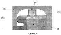
- FIG 2 is a magnified example of a connection member 125 inside of an adapter member 110 utilizing a crush rib 105.
- crush rib 105 is located at the end of an abuse protection rib 115.
- Crush rib 105 fits into adapter member 110 at the adapter member opening 120.
- the crush rib 105 prevents vibration of the connection member 125, more material continues to be removed from the crush rib 105.
- the connection member 125 may no longer have a tight fit within the adapter member opening's 120 inner walls.
- the control housing may lose its tight fit in the adapter member opening over time with use of the crush rib.
- the loss of the tight fit may be due to the constant vibration slowly removing additional material from the crush ribs over time. As more material is removed from the crush rib, the control housing may come loose from the adapter member opening and may result in rattle.
- a flex rib that may not be subject to material removal and therefore maintains vibration resistance over a longer period of time.
- a flex rib may be used on any connection or attachment member to provide a tight, vibration resistant fit of that member.
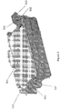
- Figure 3 is an example of a housing used for housing a control module for controlling a device configured to be repositioned.
- Figure 3 illustrates control housing 301 with connection members 310 and 315.
- Connection member 310 has a dog-leg configuration, allowing the connection member 310 to be hooked into an adapter member opening.
- Connection member 315 has a snap configuration, allowing the connection member 315 to swing into position and snap into the adaptor member opening.
- the connection members 310 and 315 may be integral with the control housing 301. For example, they may be formed of the same material at the same time by the same process.
- Connection member 310 and 315 may include a flex rib 305 and an abuse protection rib 320.
- FIG 4 is a magnified view of connection member 315.
- Figure 4 shows connection member 315 which includes flex rib 305 and abuse protection rib 320.
- Flex rib 305 includes a lead-in surface 430.
- the lead-in surface 430 allows for the connection member 315 to easily fit within an adapter member opening.
- Figures 5-8 illustrate instances of progress for the single motion of attaching the housing to an adapter member.
- Figure 5 is an example of a first instance of progress for the single motion of attaching the control housing 301 to an adapter member 505.
- Figure 5 illustrates that connection member 310 is first hooked into adapter member 505. Once connection member 310 is hooked into adapter member 505 at adapter member opening 510(a), control housing 301 is then pivoted on connection member 310, allowing connection member 315 to swing into position.
- Figure 6 is an example of a second instance of progress for the single motion of attaching the control housing 301 to the adapter member 505.
- Figure 6 illustrates adapter member 505 with adapter member opening 510 (b).
- the adapter member 505 is first contacting connection member 315.
- Connection member 315 includes a snap arm 620, a flex rib 305, and a flex rib lead-in surface 430.
- Figure 7 is an example of a third instance of progress for the single motion of attaching the control housing 301 to the adapter member 505.
- Figure 7 illustrates snap arm 620 flexing to allow the adapter member 505 to pass.
- Figure 8 is an example of a fourth and final instance of progress for the single motion of attaching the control housing 301 to the adapter member 505.
- Figure 8 illustrates snap arm 620 engaged with adapter member 505.
- the snap arm 620 retains control housing 301 vertically within adapter member 505.
- Flex ribs 305 resist transverse movement and vibration.
- Figure 9 is an example of a connection member 315 inside of an adapter member 505 utilizing flex ribs 305 and abuse protection ribs 320.
- Connection member 315 fits inside adapter member 505 at adapter member opening 510(b).
- Flex ribs 305 and abuse protection ribs 320 are located at the top and bottom of connection member 315. Flex ribs 305 and abuse protection ribs 320 are also located on the left side of connection member 315.
- connection member 315 is shown engaged within the adapter member opening 510(b).
- the flex ribs 305 are shown flexed within the adapter member opening 510(b).
- the designed interference, in-between the flex ribs 305 and the adapter member opening 510(b), may displace the ribs. This displacement may result in a constant feedback force acting against the adapter member opening's 510(b) inner walls.
- the constant feedback force may resist displacement of the connection member 315 in an environment susceptible to vibration and also absorb shock and reduce its transmission to any shock sensitive components.
- the abuse protection rib 320 is designed with clearance in-between it and the adapted member opening 510(b) wall. The abuse protection rib 320 may prevent excessive force from displacing the connection member 315 to a point of damaging the flex ribs 305.
- Figure 10 is a magnified view of Figure 9 .
- Flex ribs 305 and abuse protection ribs 320 provide a tight fit for connection member 315 in adapter member opening 510(b).
- Figure 10 shows the flex ribs 305 flexed within the adapter member opening 510(b). The designed interference displaces the flex ribs 305. This displacement results in a constant feedback force acting against the adapter member opening's 510(b) inner walls.
- the abuse protection rib 320 may prevent excessive force from displacing the connection member 315 to a point of damaging the flex ribs 305.
- Figure 11 is a top view example of a control housing 301 utilizing a flex rib 305.
- Flex rib 305 is a part of connection member 315.
- Detail A 1100 includes both flex rib 305 and abuse protection rib 320.
- Connection member 315 is part of control housing 301.
- the connection member 315, control housing 301, flex rib 305, and abuse protection rib 320 may be one piece.
- the connection member 315, control housing 301, flex rib 305, and abuse protection rib 320 may be a plastic, for example, polypropylene.
- the flex rib 305 is designed to be flexible and may be displaced with a reasonable amount of force.
- the abuse protection rib 320 may be used to limit the amount of deflection the flex rib 305 may be displaced.
- the flex rib 305 includes a lead-in surface to guide the flex rib 305 into an adapter member opening 510(b), allowing the flex rib 305 to be deflected automatically upon insertion.
- the flex rib 305 may provide dampening and may minimize movement of a control housing 301 when mounted to a vehicle. By dampening vibrations, electronics, connectors, and other devices are better protected from potential damage of loosening during vehicle operation. In addition, dampening vibrations helps reduce vehicle noise to benefit comfort of passengers within the vehicle.
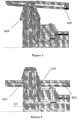
- FIG 12 is a magnified view of Detail A 1100 in Figure 11 .
- Detail A 1100 includes flex rib 305 and abuse protection rib 320.
- the abuse protection rib 320 has a certain height which is less than that of the flex rib 305. This differential in height allows the flex rib 305 to flex all the way to the height of the abuse protection rib 320. This limits the amount of deflection the flex rib 305 may be displaced.
- Figure 13 is a flow diagram of an example method 1300 for connecting a housing unit for an electronics module to an adapter member.
- the method 1300 includes providing a housing with a first connection member and a second connection member 1305.
- the first connection member may include a flex rib and an abuse protection rib.
- the method 1300 may further include attaching the first connection member to an adapter member 1310.
- the method 1300 may further include pivoting the housing on the first connection member to allow the second connection member to swing into position 1315.
- the method 1300 may further include snapping the second connection member into the adapter member at an adapter member opening 1320.
Landscapes
- Engineering & Computer Science (AREA)
- Architecture (AREA)
- Civil Engineering (AREA)
- Structural Engineering (AREA)
- Microelectronics & Electronic Packaging (AREA)
- Connector Housings Or Holding Contact Members (AREA)
- Casings For Electric Apparatus (AREA)
- Details Of Connecting Devices For Male And Female Coupling (AREA)
Description
- Vehicle control modules control various aspects of a vehicle, including controlling moving parts, such as seats, windows and rotational closure members, such as lift gates. One of the issues that designers of control modules face includes securing the electronics of the control modules within the vehicle. Generally designers use control module housings to house and secure the control modules.
- Control module housings face a number of challenges for securing electronics therein. Control housings are adapted for connection to the automobile and prevent damage to the electronics over extended periods of time and over a variety of environmental conditions, such as heat and moisture, and motion factors. In the case of the control module housing being mounted to moving parts, or non-moving parts, of a vehicle, including doors and lift gates, the housing should be designed to prevent motion including vibration and other dynamic stress factors, from damaging control electronics contained therein as damage may cause vehicle parts to malfunction that are controlled by the control modules. Accordingly, there is a need for a housing to prevent damage to control modules contained within the housing. It is also important that the module does not rattle against the mounting plate, or adapter member, causing unwanted noise. When a mechanical shock is applied to the adapter member, flex ribs may cushion the shock inside the module, reducing the chance of damage to electronic components.
US 2008/2455544 A1 describes a housing unit for securing electronics of a control module to a vehicle, which may include a housing and at least two connection members. Crush-ribs are included on the connection members and are configured to contact the adaptor member to substantially eliminate transverse movement of the housing. The housing is able to position, support, and minimize vibration of the electronics, where the electronics maybe disposed on a printed circuit board (see e.g. abstract &Fig. 5 ). - The present invention discloses a housing for an electronics module according to claim 1. In detail a housing unit for an electronics module is claimed, wherein the housing unit comprises the following: a housing configured to secure electronics of an electronics module; a connection member disposed on one side of the housing; a flex rib attached to the connection member; and an abuse protection rib connected to the connection member. The housing unit is characterized in that the flex rib is configured to be deflected upon insertion and wherein a height of the abuse protection rib is less than a height of the flex rib such that the height of the abuse protection rib limits an amount of deflection of the flex rib.
- Furthermore, the present invention discloses a method according to claim 8; in detail a method for connecting a housing unit for an electronics module to an adapter member, wherein the method comprises:
- providing a housing with a first connection member and a second connection member, wherein the first connection member includes a flex rib and an abuse protection rib, the flex rib configured to be deflected upon insertion;
- attaching the first connection member to an adapter member;
- pivoting the housing on the first connection member to allow the second connection member to swing into position;
- snapping the second connection member into the adapter member at an adapter member opening; and
- limiting an amount of deflection of the flex rib with the abuse protection rib.
- A more detailed understanding may be had from the following description, given by way of example in conjunction with the accompanying drawings wherein:
-
FIG. 1 is an example of a connection member inside of an adapter member utilizing a crush rib; -
FIG. 2 is a magnified example of a connection member inside of an adapter member utilizing a crush rib; -
FIG. 3 is an example of a housing used for housing a control module for controlling a device configured to be repositioned; -
FIG. 4 is a magnified view of connection member; -
FIG. 5 is an example of a first instance of progress for the single motion of attaching the housing to an adapter member; -
FIG. 6 is an example of a second instance of progress for the single motion of attaching the housing to the adapter member; -
FIG. 7 is an example of a third instance of progress for the single motion of attaching the housing to the adapter member; -
FIG. 8 is an example of a fourth and final instance of progress for the single motion of attaching the housing to the adapter member; -
FIG. 9 is an example of a connection member inside of an adapter member utilizing flex ribs and abuse protection ribs; -
FIG. 10 is a magnified view ofFigure 9 ; -
FIG. 11 is a top view example of a control housing utilizing a flex rib; -
FIG. 12 is a magnified view of Detail A inFigure 11 ; and -
FIG. 13 is a flow diagram of an example method for connecting a housing unit for an electronics module to an adapter member. - This invention is described in the following description with reference to the Figures, in which like reference numbers represent the same or similar elements. The embodiments and variations of the invention described herein, and/or shown in the drawings, are presented by way of example only and are not limiting as to the scope of the invention. Unless otherwise specifically stated, individual aspects and components of the invention may be omitted or modified, or may have substituted therefore known equivalents, or as yet unknown substitutes such as may be developed in the future or such as may be found to be acceptable substitutes in the future. The invention may also be modified for a variety of applications, since the range of potential applications is great, and since it is intended that the present invention be adaptable to many such variations.
-
Figure 1 is an example of aconnection member 125 of a control housing inside of anadapter member 110 utilizing acrush rib 105. Crush rib 105 is used to prevent vibration of aconnection member 125 by abutting an adapter member opening 120 ofadapter member 110.Abuse protection rib 115 provides stability for thecrush rib 105. Crushrib 105 is located at the end ofabuse protection rib 115. Crush rib 105 interferes with the adapter member opening 120, causing material to be removed from thecrush rib 105 during insertion. The removal of the material fromcrush rib 105 results in a tight fit within the adapter member opening's 120 inner walls. - Currently a crush rib design may be used in which the crush rib is shaved off during insertion of the connection member into the adapter member. The remaining material may compensate for any fluctuating tolerances and provide a vibration resistant fit.
-
Figure 2 is a magnified example of aconnection member 125 inside of anadapter member 110 utilizing acrush rib 105. As illustrated inFigure 2 ,crush rib 105 is located at the end of anabuse protection rib 115. Crush rib 105 fits intoadapter member 110 at the adapter member opening 120. As thecrush rib 105 prevents vibration of theconnection member 125, more material continues to be removed from thecrush rib 105. As more material is removed from thecrush rib 105, theconnection member 125 may no longer have a tight fit within the adapter member opening's 120 inner walls. - The control housing may lose its tight fit in the adapter member opening over time with use of the crush rib. The loss of the tight fit may be due to the constant vibration slowly removing additional material from the crush ribs over time. As more material is removed from the crush rib, the control housing may come loose from the adapter member opening and may result in rattle.
- Described herein is a flex rib that may not be subject to material removal and therefore maintains vibration resistance over a longer period of time. A flex rib may be used on any connection or attachment member to provide a tight, vibration resistant fit of that member.
-
Figure 3 is an example of a housing used for housing a control module for controlling a device configured to be repositioned.Figure 3 illustratescontrol housing 301 withconnection members Connection member 310 has a dog-leg configuration, allowing theconnection member 310 to be hooked into an adapter member opening.Connection member 315 has a snap configuration, allowing theconnection member 315 to swing into position and snap into the adaptor member opening. Theconnection members control housing 301. For example, they may be formed of the same material at the same time by the same process.Connection member flex rib 305 and anabuse protection rib 320. -
Figure 4 is a magnified view ofconnection member 315.Figure 4 showsconnection member 315 which includesflex rib 305 andabuse protection rib 320.Flex rib 305 includes a lead-insurface 430. The lead-insurface 430 allows for theconnection member 315 to easily fit within an adapter member opening. -
Figures 5-8 illustrate instances of progress for the single motion of attaching the housing to an adapter member. -
Figure 5 is an example of a first instance of progress for the single motion of attaching thecontrol housing 301 to anadapter member 505.Figure 5 illustrates thatconnection member 310 is first hooked intoadapter member 505. Onceconnection member 310 is hooked intoadapter member 505 at adapter member opening 510(a), controlhousing 301 is then pivoted onconnection member 310, allowingconnection member 315 to swing into position. -
Figure 6 is an example of a second instance of progress for the single motion of attaching thecontrol housing 301 to theadapter member 505.Figure 6 illustratesadapter member 505 with adapter member opening 510 (b). Theadapter member 505 is first contactingconnection member 315.Connection member 315 includes asnap arm 620, aflex rib 305, and a flex rib lead-insurface 430. -
Figure 7 is an example of a third instance of progress for the single motion of attaching thecontrol housing 301 to theadapter member 505.Figure 7 illustratessnap arm 620 flexing to allow theadapter member 505 to pass. -
Figure 8 is an example of a fourth and final instance of progress for the single motion of attaching thecontrol housing 301 to theadapter member 505.Figure 8 illustratessnap arm 620 engaged withadapter member 505. Thesnap arm 620 retainscontrol housing 301 vertically withinadapter member 505.Flex ribs 305 resist transverse movement and vibration. -
Figure 9 is an example of aconnection member 315 inside of anadapter member 505 utilizingflex ribs 305 andabuse protection ribs 320.Connection member 315 fits insideadapter member 505 at adapter member opening 510(b).Flex ribs 305 andabuse protection ribs 320 are located at the top and bottom ofconnection member 315.Flex ribs 305 andabuse protection ribs 320 are also located on the left side ofconnection member 315. - The
connection member 315 is shown engaged within the adapter member opening 510(b). Theflex ribs 305 are shown flexed within the adapter member opening 510(b). The designed interference, in-between theflex ribs 305 and the adapter member opening 510(b), may displace the ribs. This displacement may result in a constant feedback force acting against the adapter member opening's 510(b) inner walls. The constant feedback force may resist displacement of theconnection member 315 in an environment susceptible to vibration and also absorb shock and reduce its transmission to any shock sensitive components. Theabuse protection rib 320 is designed with clearance in-between it and the adapted member opening 510(b) wall. Theabuse protection rib 320 may prevent excessive force from displacing theconnection member 315 to a point of damaging theflex ribs 305. -
Figure 10 is a magnified view ofFigure 9 .Flex ribs 305 andabuse protection ribs 320 provide a tight fit forconnection member 315 in adapter member opening 510(b).Figure 10 shows theflex ribs 305 flexed within the adapter member opening 510(b). The designed interference displaces theflex ribs 305. This displacement results in a constant feedback force acting against the adapter member opening's 510(b) inner walls. Theabuse protection rib 320 may prevent excessive force from displacing theconnection member 315 to a point of damaging theflex ribs 305. -
Figure 11 is a top view example of acontrol housing 301 utilizing aflex rib 305.Flex rib 305 is a part ofconnection member 315.Detail A 1100 includes bothflex rib 305 andabuse protection rib 320.Connection member 315 is part ofcontrol housing 301. Theconnection member 315, controlhousing 301,flex rib 305, andabuse protection rib 320 may be one piece. Theconnection member 315, controlhousing 301,flex rib 305, andabuse protection rib 320 may be a plastic, for example, polypropylene. - The
flex rib 305 is designed to be flexible and may be displaced with a reasonable amount of force. Theabuse protection rib 320 may be used to limit the amount of deflection theflex rib 305 may be displaced. Theflex rib 305 includes a lead-in surface to guide theflex rib 305 into an adapter member opening 510(b), allowing theflex rib 305 to be deflected automatically upon insertion. - For example, the
flex rib 305 may provide dampening and may minimize movement of acontrol housing 301 when mounted to a vehicle. By dampening vibrations, electronics, connectors, and other devices are better protected from potential damage of loosening during vehicle operation. In addition, dampening vibrations helps reduce vehicle noise to benefit comfort of passengers within the vehicle. -
Figure 12 is a magnified view ofDetail A 1100 inFigure 11 . Detail
A 1100 includesflex rib 305 andabuse protection rib 320. As illustrated inFigure 12 , theabuse protection rib 320 has a certain height which is less than that of theflex rib 305. This differential in height allows theflex rib 305 to flex all the way to the height of theabuse protection rib 320. This limits the amount of deflection theflex rib 305 may be displaced. -
Figure 13 is a flow diagram of anexample method 1300 for connecting a housing unit for an electronics module to an adapter member. Themethod 1300 includes providing a housing with a first connection member and asecond connection member 1305. The first connection member may include a flex rib and an abuse protection rib. Themethod 1300 may further include attaching the first connection member to anadapter member 1310. Themethod 1300 may further include pivoting the housing on the first connection member to allow the second connection member to swing intoposition 1315. Themethod 1300 may further include snapping the second connection member into the adapter member at anadapter member opening 1320.
Claims (14)
- A housing unit for an electronics module, the housing unit comprising:a housing (301) configured to secure electronics of an electronics module;a connection member (310) disposed on one side of the housing;a flex rib (305) attached to the connection member; andan abuse protection rib (320) connected to the connection member,characterized in thatthe flex rib is configured to be deflected upon insertion and wherein a height of the abuse protection rib (320) is less than a height of the flex rib (305) such that the height of the abuse protection rib limits an amount of deflection of the flex rib.
- The housing unit of claim 1, wherein the flex rib (305) includes a lead-in surface (430) to guide the flex rib into an adapter member opening.
- The housing unit of claim 1, wherein the flex rib (305) is displaced with a reasonable amount of force.
- The housing unit of claim 3, wherein the displacement of the flex rib (305) results in a feedback force to resist displacement of the connection member in an adapter member opening (510).
- The housing unit of claim 4, wherein the flex rib (305) prevents the connection member from rattling in the adapter member opening.
- The housing unit of claim 1, wherein the housing (301), the connection member (315), the flex rib (305), and the abuse protection rib (320) are one piece.
- The housing unit of claim 1, wherein the housing (301), the connection member (315), the flex rib (305), and the abuse protection rib (320) are made of plastic.
- A method for connecting a housing unit for an electronics module to an adapter member, the method comprising:providing a housing with a first connection member and a second connection member, wherein the first connection member includes a flex rib and an abuse protection rib, the flex rib configured to be deflected upon insertion;attaching the first connection member to an adapter member;pivoting the housing on the first connection member to allow the second connection member to swing into position;snapping the second connection member into the adapter member at an adapter member opening; andlimiting an amount of deflection of the flex rib with the abuse protection rib.
- The method of claim 8, wherein the flex rib includes a lead-in surface to guide the flex rib into the adapter member opening.
- The method of claim 8, wherein the flex rib is displaced with a reasonable amount of force.
- The method of claim 10, wherein the displacement of the flex rib results in a feed force to resist displacement of the connection member in the adapter member opening.
- The method of claim 11, wherein the flex rib prevents the connection member from rattling in the adapter member opening.
- The method of claim 8, wherein the housing, the connection member, the flex rib, and the abuse protection rib are one piece.
- The method of claim 8, wherein the housing, the connection member, the flex rib, and the abuse protection rib are made of plastic.
Applications Claiming Priority (2)
| Application Number | Priority Date | Filing Date | Title |
|---|---|---|---|
| US13/601,055 US8723035B2 (en) | 2012-08-31 | 2012-08-31 | Vibration reduction rib |
| PCT/US2013/056993 WO2014036087A1 (en) | 2012-08-31 | 2013-08-28 | Vibration reduction rib |
Publications (2)
| Publication Number | Publication Date |
|---|---|
| EP2891394A1 EP2891394A1 (en) | 2015-07-08 |
| EP2891394B1 true EP2891394B1 (en) | 2018-05-02 |
Family
ID=49162242
Family Applications (1)
| Application Number | Title | Priority Date | Filing Date |
|---|---|---|---|
| EP13760183.7A Not-in-force EP2891394B1 (en) | 2012-08-31 | 2013-08-28 | Vibration reduction rib |
Country Status (5)
| Country | Link |
|---|---|
| US (1) | US8723035B2 (en) |
| EP (1) | EP2891394B1 (en) |
| CN (1) | CN104782240B (en) |
| ES (1) | ES2674794T3 (en) |
| WO (1) | WO2014036087A1 (en) |
Families Citing this family (5)
| Publication number | Priority date | Publication date | Assignee | Title |
|---|---|---|---|---|
| FR3001603B1 (en) * | 2013-01-29 | 2015-03-20 | Airbus Operations Sas | ELECTRONIC CARD FOR AVIONIC EQUIPMENT COMPRISING VIBRATION SHOCK MEANS BETWEEN ITS REINFORCING FRAME AND ITS MEANS OF MAINTENANCE |
| DE202017001367U1 (en) | 2016-03-14 | 2017-05-05 | Continental Automotive Gmbh | Sheet metal housing for an electronic control unit |
| EP3305610B1 (en) * | 2016-10-10 | 2020-12-16 | WABCO Europe BVBA | Electronic control unit for a vehicle, in particular commercial vehicle |
| US11142147B2 (en) * | 2019-06-28 | 2021-10-12 | Sumitomo Wiring Systems, Ltd. | Power distribution box assembly for a vehicle |
| USD1121561S1 (en) * | 2023-09-27 | 2026-04-07 | Bizlink Industry Germany Gmbh | Base plate |
Family Cites Families (12)
| Publication number | Priority date | Publication date | Assignee | Title |
|---|---|---|---|---|
| US5950973A (en) * | 1997-04-21 | 1999-09-14 | Delco Electronics | Housing mounting system |
| US6126458A (en) * | 1999-07-13 | 2000-10-03 | Yazaki North America, Inc. | Bussed electrical center assembly with connector pre-set |
| US6441304B1 (en) * | 2000-05-05 | 2002-08-27 | The Wiremold Company | Electrical outlet assembly |
| ES2169697B1 (en) * | 2000-11-03 | 2003-11-01 | Lear Automotive Eeds Spain | PERFECTED DEVICE FOR FIXING DISTRIBUTION BOXES. |
| US6570088B1 (en) * | 2002-03-13 | 2003-05-27 | Sumitomo Wiring Systems, Ltd. | Junction box assembly |
| DE10235339A1 (en) * | 2002-08-02 | 2004-02-12 | Robert Bosch Gmbh | fastening device |
| JP2005042770A (en) * | 2003-07-24 | 2005-02-17 | Sumitomo Wiring Syst Ltd | Locking structure of clamp |
| JP2007068377A (en) * | 2005-09-02 | 2007-03-15 | Yazaki Corp | Electrical junction box |
| DE102006027751A1 (en) * | 2006-06-16 | 2007-12-20 | Robert Bosch Gmbh | Fastening element for fastening and / or prefixing of a component to a holder provided with an opening and component with fastening element |
| JP4858075B2 (en) * | 2006-10-20 | 2012-01-18 | 住友電装株式会社 | In-vehicle electrical junction box |
| JP5088811B2 (en) * | 2007-01-10 | 2012-12-05 | 矢崎総業株式会社 | Electrical junction box |
| US7718892B2 (en) * | 2007-04-06 | 2010-05-18 | Flextronics Automotive Inc. | Control module housing |
-
2012
- 2012-08-31 US US13/601,055 patent/US8723035B2/en active Active
-
2013
- 2013-08-28 ES ES13760183.7T patent/ES2674794T3/en active Active
- 2013-08-28 EP EP13760183.7A patent/EP2891394B1/en not_active Not-in-force
- 2013-08-28 CN CN201380054718.2A patent/CN104782240B/en active Active
- 2013-08-28 WO PCT/US2013/056993 patent/WO2014036087A1/en not_active Ceased
Non-Patent Citations (1)
| Title |
|---|
| None * |
Also Published As
| Publication number | Publication date |
|---|---|
| ES2674794T3 (en) | 2018-07-04 |
| US8723035B2 (en) | 2014-05-13 |
| CN104782240B (en) | 2016-11-02 |
| WO2014036087A1 (en) | 2014-03-06 |
| EP2891394A1 (en) | 2015-07-08 |
| US20140062271A1 (en) | 2014-03-06 |
| CN104782240A (en) | 2015-07-15 |
Similar Documents
| Publication | Publication Date | Title |
|---|---|---|
| US8723035B2 (en) | Vibration reduction rib | |
| US9630573B2 (en) | Clip mounting seats of interior components or exterior components | |
| US7718892B2 (en) | Control module housing | |
| US7540749B1 (en) | Connector assemblies and systems | |
| US8654525B2 (en) | Clips and latch to receive a computing component | |
| CN113544016A (en) | Mounting rack assembly | |
| CN104284564A (en) | Fan cover having vibration suppressing mechanism of fan motor, and motor drive unit | |
| JP5006143B2 (en) | Elastic body mounting structure | |
| EP2058723B1 (en) | Shock absorbing structure of computer storage device | |
| CN203640451U (en) | Automobile back door lock pin assembly | |
| US10215207B2 (en) | Support member | |
| US9564698B2 (en) | Capacitor frame assembly | |
| JP5821682B2 (en) | Anti-rattle structure for electrical parts | |
| US7909627B2 (en) | Multi-axis retention mechanism | |
| WO2015187728A1 (en) | Console assembly | |
| JP7858517B2 (en) | Electronic equipment protective devices and electronic equipment units | |
| JP5999638B2 (en) | Electronic unit mounting structure | |
| WO2021046093A1 (en) | Double hook snap fit for electronic housing | |
| KR20220147841A (en) | Electronic control device | |
| JP7113780B2 (en) | In-vehicle electronic equipment | |
| CN220753074U (en) | Vehicle-mounted hard disk box and vehicle-mounted hard disk system | |
| JP5760805B2 (en) | Vehicle protector | |
| JP5083693B2 (en) | Corner unit for cuboid object holder and cuboid object holder | |
| JP2021018168A (en) | Electronic device | |
| CN116457237A (en) | Battery device with non-conductive protective plate |
Legal Events
| Date | Code | Title | Description |
|---|---|---|---|
| PUAI | Public reference made under article 153(3) epc to a published international application that has entered the european phase |
Free format text: ORIGINAL CODE: 0009012 |
|
| 17P | Request for examination filed |
Effective date: 20150326 |
|
| AK | Designated contracting states |
Kind code of ref document: A1 Designated state(s): AL AT BE BG CH CY CZ DE DK EE ES FI FR GB GR HR HU IE IS IT LI LT LU LV MC MK MT NL NO PL PT RO RS SE SI SK SM TR |
|
| AX | Request for extension of the european patent |
Extension state: BA ME |
|
| DAX | Request for extension of the european patent (deleted) | ||
| GRAP | Despatch of communication of intention to grant a patent |
Free format text: ORIGINAL CODE: EPIDOSNIGR1 |
|
| INTG | Intention to grant announced |
Effective date: 20171127 |
|
| GRAS | Grant fee paid |
Free format text: ORIGINAL CODE: EPIDOSNIGR3 |
|
| GRAA | (expected) grant |
Free format text: ORIGINAL CODE: 0009210 |
|
| AK | Designated contracting states |
Kind code of ref document: B1 Designated state(s): AL AT BE BG CH CY CZ DE DK EE ES FI FR GB GR HR HU IE IS IT LI LT LU LV MC MK MT NL NO PL PT RO RS SE SI SK SM TR |
|
| REG | Reference to a national code |
Ref country code: GB Ref legal event code: FG4D |
|
| REG | Reference to a national code |
Ref country code: CH Ref legal event code: EP Ref country code: AT Ref legal event code: REF Ref document number: 996625 Country of ref document: AT Kind code of ref document: T Effective date: 20180515 |
|
| REG | Reference to a national code |
Ref country code: DE Ref legal event code: R096 Ref document number: 602013036913 Country of ref document: DE Ref country code: IE Ref legal event code: FG4D |
|
| REG | Reference to a national code |
Ref country code: ES Ref legal event code: FG2A Ref document number: 2674794 Country of ref document: ES Kind code of ref document: T3 Effective date: 20180704 |
|
| RAP2 | Party data changed (patent owner data changed or rights of a patent transferred) |
Owner name: FLEXTRONICS AP, LLC |
|
| REG | Reference to a national code |
Ref country code: FR Ref legal event code: PLFP Year of fee payment: 6 |
|
| REG | Reference to a national code |
Ref country code: NL Ref legal event code: MP Effective date: 20180502 |
|
| REG | Reference to a national code |
Ref country code: LT Ref legal event code: MG4D |
|
| PG25 | Lapsed in a contracting state [announced via postgrant information from national office to epo] |
Ref country code: NO Free format text: LAPSE BECAUSE OF FAILURE TO SUBMIT A TRANSLATION OF THE DESCRIPTION OR TO PAY THE FEE WITHIN THE PRESCRIBED TIME-LIMIT Effective date: 20180802 Ref country code: SE Free format text: LAPSE BECAUSE OF FAILURE TO SUBMIT A TRANSLATION OF THE DESCRIPTION OR TO PAY THE FEE WITHIN THE PRESCRIBED TIME-LIMIT Effective date: 20180502 Ref country code: FI Free format text: LAPSE BECAUSE OF FAILURE TO SUBMIT A TRANSLATION OF THE DESCRIPTION OR TO PAY THE FEE WITHIN THE PRESCRIBED TIME-LIMIT Effective date: 20180502 Ref country code: BG Free format text: LAPSE BECAUSE OF FAILURE TO SUBMIT A TRANSLATION OF THE DESCRIPTION OR TO PAY THE FEE WITHIN THE PRESCRIBED TIME-LIMIT Effective date: 20180802 Ref country code: LT Free format text: LAPSE BECAUSE OF FAILURE TO SUBMIT A TRANSLATION OF THE DESCRIPTION OR TO PAY THE FEE WITHIN THE PRESCRIBED TIME-LIMIT Effective date: 20180502 |
|
| PG25 | Lapsed in a contracting state [announced via postgrant information from national office to epo] |
Ref country code: NL Free format text: LAPSE BECAUSE OF FAILURE TO SUBMIT A TRANSLATION OF THE DESCRIPTION OR TO PAY THE FEE WITHIN THE PRESCRIBED TIME-LIMIT Effective date: 20180502 Ref country code: RS Free format text: LAPSE BECAUSE OF FAILURE TO SUBMIT A TRANSLATION OF THE DESCRIPTION OR TO PAY THE FEE WITHIN THE PRESCRIBED TIME-LIMIT Effective date: 20180502 Ref country code: HR Free format text: LAPSE BECAUSE OF FAILURE TO SUBMIT A TRANSLATION OF THE DESCRIPTION OR TO PAY THE FEE WITHIN THE PRESCRIBED TIME-LIMIT Effective date: 20180502 Ref country code: GR Free format text: LAPSE BECAUSE OF FAILURE TO SUBMIT A TRANSLATION OF THE DESCRIPTION OR TO PAY THE FEE WITHIN THE PRESCRIBED TIME-LIMIT Effective date: 20180803 Ref country code: LV Free format text: LAPSE BECAUSE OF FAILURE TO SUBMIT A TRANSLATION OF THE DESCRIPTION OR TO PAY THE FEE WITHIN THE PRESCRIBED TIME-LIMIT Effective date: 20180502 |
|
| REG | Reference to a national code |
Ref country code: AT Ref legal event code: MK05 Ref document number: 996625 Country of ref document: AT Kind code of ref document: T Effective date: 20180502 |
|
| PG25 | Lapsed in a contracting state [announced via postgrant information from national office to epo] |
Ref country code: CZ Free format text: LAPSE BECAUSE OF FAILURE TO SUBMIT A TRANSLATION OF THE DESCRIPTION OR TO PAY THE FEE WITHIN THE PRESCRIBED TIME-LIMIT Effective date: 20180502 Ref country code: RO Free format text: LAPSE BECAUSE OF FAILURE TO SUBMIT A TRANSLATION OF THE DESCRIPTION OR TO PAY THE FEE WITHIN THE PRESCRIBED TIME-LIMIT Effective date: 20180502 Ref country code: DK Free format text: LAPSE BECAUSE OF FAILURE TO SUBMIT A TRANSLATION OF THE DESCRIPTION OR TO PAY THE FEE WITHIN THE PRESCRIBED TIME-LIMIT Effective date: 20180502 Ref country code: EE Free format text: LAPSE BECAUSE OF FAILURE TO SUBMIT A TRANSLATION OF THE DESCRIPTION OR TO PAY THE FEE WITHIN THE PRESCRIBED TIME-LIMIT Effective date: 20180502 Ref country code: AT Free format text: LAPSE BECAUSE OF FAILURE TO SUBMIT A TRANSLATION OF THE DESCRIPTION OR TO PAY THE FEE WITHIN THE PRESCRIBED TIME-LIMIT Effective date: 20180502 Ref country code: SK Free format text: LAPSE BECAUSE OF FAILURE TO SUBMIT A TRANSLATION OF THE DESCRIPTION OR TO PAY THE FEE WITHIN THE PRESCRIBED TIME-LIMIT Effective date: 20180502 Ref country code: PL Free format text: LAPSE BECAUSE OF FAILURE TO SUBMIT A TRANSLATION OF THE DESCRIPTION OR TO PAY THE FEE WITHIN THE PRESCRIBED TIME-LIMIT Effective date: 20180502 |
|
| REG | Reference to a national code |
Ref country code: DE Ref legal event code: R097 Ref document number: 602013036913 Country of ref document: DE |
|
| PG25 | Lapsed in a contracting state [announced via postgrant information from national office to epo] |
Ref country code: SM Free format text: LAPSE BECAUSE OF FAILURE TO SUBMIT A TRANSLATION OF THE DESCRIPTION OR TO PAY THE FEE WITHIN THE PRESCRIBED TIME-LIMIT Effective date: 20180502 |
|
| PLBE | No opposition filed within time limit |
Free format text: ORIGINAL CODE: 0009261 |
|
| STAA | Information on the status of an ep patent application or granted ep patent |
Free format text: STATUS: NO OPPOSITION FILED WITHIN TIME LIMIT |
|
| PG25 | Lapsed in a contracting state [announced via postgrant information from national office to epo] |
Ref country code: MC Free format text: LAPSE BECAUSE OF FAILURE TO SUBMIT A TRANSLATION OF THE DESCRIPTION OR TO PAY THE FEE WITHIN THE PRESCRIBED TIME-LIMIT Effective date: 20180502 |
|
| REG | Reference to a national code |
Ref country code: CH Ref legal event code: PL |
|
| 26N | No opposition filed |
Effective date: 20190205 |
|
| PG25 | Lapsed in a contracting state [announced via postgrant information from national office to epo] |
Ref country code: CH Free format text: LAPSE BECAUSE OF NON-PAYMENT OF DUE FEES Effective date: 20180831 Ref country code: LI Free format text: LAPSE BECAUSE OF NON-PAYMENT OF DUE FEES Effective date: 20180831 Ref country code: LU Free format text: LAPSE BECAUSE OF NON-PAYMENT OF DUE FEES Effective date: 20180828 |
|
| REG | Reference to a national code |
Ref country code: BE Ref legal event code: MM Effective date: 20180831 |
|
| PG25 | Lapsed in a contracting state [announced via postgrant information from national office to epo] |
Ref country code: SI Free format text: LAPSE BECAUSE OF FAILURE TO SUBMIT A TRANSLATION OF THE DESCRIPTION OR TO PAY THE FEE WITHIN THE PRESCRIBED TIME-LIMIT Effective date: 20180502 |
|
| PG25 | Lapsed in a contracting state [announced via postgrant information from national office to epo] |
Ref country code: BE Free format text: LAPSE BECAUSE OF NON-PAYMENT OF DUE FEES Effective date: 20180831 |
|
| PG25 | Lapsed in a contracting state [announced via postgrant information from national office to epo] |
Ref country code: AL Free format text: LAPSE BECAUSE OF FAILURE TO SUBMIT A TRANSLATION OF THE DESCRIPTION OR TO PAY THE FEE WITHIN THE PRESCRIBED TIME-LIMIT Effective date: 20180502 |
|
| PG25 | Lapsed in a contracting state [announced via postgrant information from national office to epo] |
Ref country code: MT Free format text: LAPSE BECAUSE OF NON-PAYMENT OF DUE FEES Effective date: 20180828 |
|
| PG25 | Lapsed in a contracting state [announced via postgrant information from national office to epo] |
Ref country code: TR Free format text: LAPSE BECAUSE OF FAILURE TO SUBMIT A TRANSLATION OF THE DESCRIPTION OR TO PAY THE FEE WITHIN THE PRESCRIBED TIME-LIMIT Effective date: 20180502 |
|
| PG25 | Lapsed in a contracting state [announced via postgrant information from national office to epo] |
Ref country code: PT Free format text: LAPSE BECAUSE OF FAILURE TO SUBMIT A TRANSLATION OF THE DESCRIPTION OR TO PAY THE FEE WITHIN THE PRESCRIBED TIME-LIMIT Effective date: 20180502 |
|
| PG25 | Lapsed in a contracting state [announced via postgrant information from national office to epo] |
Ref country code: CY Free format text: LAPSE BECAUSE OF FAILURE TO SUBMIT A TRANSLATION OF THE DESCRIPTION OR TO PAY THE FEE WITHIN THE PRESCRIBED TIME-LIMIT Effective date: 20180502 Ref country code: IE Free format text: LAPSE BECAUSE OF NON-PAYMENT OF DUE FEES Effective date: 20180828 Ref country code: HU Free format text: LAPSE BECAUSE OF FAILURE TO SUBMIT A TRANSLATION OF THE DESCRIPTION OR TO PAY THE FEE WITHIN THE PRESCRIBED TIME-LIMIT; INVALID AB INITIO Effective date: 20130828 Ref country code: MK Free format text: LAPSE BECAUSE OF NON-PAYMENT OF DUE FEES Effective date: 20180502 |
|
| PG25 | Lapsed in a contracting state [announced via postgrant information from national office to epo] |
Ref country code: IS Free format text: LAPSE BECAUSE OF FAILURE TO SUBMIT A TRANSLATION OF THE DESCRIPTION OR TO PAY THE FEE WITHIN THE PRESCRIBED TIME-LIMIT Effective date: 20180902 |
|
| PGFP | Annual fee paid to national office [announced via postgrant information from national office to epo] |
Ref country code: IT Payment date: 20230822 Year of fee payment: 11 Ref country code: GB Payment date: 20230822 Year of fee payment: 11 Ref country code: ES Payment date: 20230914 Year of fee payment: 11 |
|
| PGFP | Annual fee paid to national office [announced via postgrant information from national office to epo] |
Ref country code: FR Payment date: 20230824 Year of fee payment: 11 Ref country code: DE Payment date: 20230828 Year of fee payment: 11 |
|
| REG | Reference to a national code |
Ref country code: DE Ref legal event code: R119 Ref document number: 602013036913 Country of ref document: DE |
|
| GBPC | Gb: european patent ceased through non-payment of renewal fee |
Effective date: 20240828 |
|
| PG25 | Lapsed in a contracting state [announced via postgrant information from national office to epo] |
Ref country code: DE Free format text: LAPSE BECAUSE OF NON-PAYMENT OF DUE FEES Effective date: 20250301 |
|
| PG25 | Lapsed in a contracting state [announced via postgrant information from national office to epo] |
Ref country code: GB Free format text: LAPSE BECAUSE OF NON-PAYMENT OF DUE FEES Effective date: 20240828 |
|
| PG25 | Lapsed in a contracting state [announced via postgrant information from national office to epo] |
Ref country code: IT Free format text: LAPSE BECAUSE OF NON-PAYMENT OF DUE FEES Effective date: 20240828 |
|
| PG25 | Lapsed in a contracting state [announced via postgrant information from national office to epo] |
Ref country code: FR Free format text: LAPSE BECAUSE OF NON-PAYMENT OF DUE FEES Effective date: 20240831 |
|
| REG | Reference to a national code |
Ref country code: ES Ref legal event code: FD2A Effective date: 20251003 |
|
| PG25 | Lapsed in a contracting state [announced via postgrant information from national office to epo] |
Ref country code: ES Free format text: LAPSE BECAUSE OF NON-PAYMENT OF DUE FEES Effective date: 20240829 |