EP2891221B2 - Power distribution system loss reduction with distributed energy resource control - Google Patents
Power distribution system loss reduction with distributed energy resource control Download PDFInfo
- Publication number
- EP2891221B2 EP2891221B2 EP13760196.9A EP13760196A EP2891221B2 EP 2891221 B2 EP2891221 B2 EP 2891221B2 EP 13760196 A EP13760196 A EP 13760196A EP 2891221 B2 EP2891221 B2 EP 2891221B2
- Authority
- EP
- European Patent Office
- Prior art keywords
- voltage magnitude
- distributed energy
- capacitor banks
- energy resources
- set points
- Prior art date
- Legal status (The legal status is an assumption and is not a legal conclusion. Google has not performed a legal analysis and makes no representation as to the accuracy of the status listed.)
- Active
Links
- 230000009467 reduction Effects 0.000 title claims description 56
- 238000009826 distribution Methods 0.000 title claims description 54
- 239000003990 capacitor Substances 0.000 claims description 85
- 230000008859 change Effects 0.000 claims description 25
- 238000000034 method Methods 0.000 claims description 23
- 230000001186 cumulative effect Effects 0.000 claims description 9
- 230000000694 effects Effects 0.000 claims description 2
- 238000009472 formulation Methods 0.000 description 16
- 239000000203 mixture Substances 0.000 description 16
- 239000000243 solution Substances 0.000 description 16
- 230000003190 augmentative effect Effects 0.000 description 12
- 230000006870 function Effects 0.000 description 11
- 230000035945 sensitivity Effects 0.000 description 10
- 230000009471 action Effects 0.000 description 9
- 238000011946 reduction process Methods 0.000 description 9
- 238000005457 optimization Methods 0.000 description 6
- 101150097504 LHX1 gene Proteins 0.000 description 4
- 101100454869 Rattus norvegicus Lhx5 gene Proteins 0.000 description 4
- 238000004146 energy storage Methods 0.000 description 4
- 239000000446 fuel Substances 0.000 description 4
- VNWKTOKETHGBQD-UHFFFAOYSA-N methane Chemical compound C VNWKTOKETHGBQD-UHFFFAOYSA-N 0.000 description 4
- 238000004364 calculation method Methods 0.000 description 3
- 230000007423 decrease Effects 0.000 description 3
- 230000001939 inductive effect Effects 0.000 description 3
- 230000008569 process Effects 0.000 description 3
- 230000004044 response Effects 0.000 description 3
- 101100129500 Caenorhabditis elegans max-2 gene Proteins 0.000 description 2
- 238000002485 combustion reaction Methods 0.000 description 2
- 238000004590 computer program Methods 0.000 description 2
- 238000005094 computer simulation Methods 0.000 description 2
- 238000010586 diagram Methods 0.000 description 2
- 239000003345 natural gas Substances 0.000 description 2
- 230000035515 penetration Effects 0.000 description 2
- 238000010248 power generation Methods 0.000 description 2
- 238000012384 transportation and delivery Methods 0.000 description 2
- 238000010521 absorption reaction Methods 0.000 description 1
- 238000004458 analytical method Methods 0.000 description 1
- 230000033228 biological regulation Effects 0.000 description 1
- 239000003795 chemical substances by application Substances 0.000 description 1
- 230000003247 decreasing effect Effects 0.000 description 1
- 230000001419 dependent effect Effects 0.000 description 1
- 230000005684 electric field Effects 0.000 description 1
- 238000005516 engineering process Methods 0.000 description 1
- 230000007613 environmental effect Effects 0.000 description 1
- 238000002347 injection Methods 0.000 description 1
- 239000007924 injection Substances 0.000 description 1
- 238000007726 management method Methods 0.000 description 1
- 230000000750 progressive effect Effects 0.000 description 1
- 238000010206 sensitivity analysis Methods 0.000 description 1
- 230000001360 synchronised effect Effects 0.000 description 1
Images


Classifications
-
- H—ELECTRICITY
- H02—GENERATION; CONVERSION OR DISTRIBUTION OF ELECTRIC POWER
- H02J—CIRCUIT ARRANGEMENTS OR SYSTEMS FOR SUPPLYING OR DISTRIBUTING ELECTRIC POWER; SYSTEMS FOR STORING ELECTRIC ENERGY
- H02J3/00—Circuit arrangements for ac mains or ac distribution networks
- H02J3/18—Arrangements for adjusting, eliminating or compensating reactive power in networks
-
- Y—GENERAL TAGGING OF NEW TECHNOLOGICAL DEVELOPMENTS; GENERAL TAGGING OF CROSS-SECTIONAL TECHNOLOGIES SPANNING OVER SEVERAL SECTIONS OF THE IPC; TECHNICAL SUBJECTS COVERED BY FORMER USPC CROSS-REFERENCE ART COLLECTIONS [XRACs] AND DIGESTS
- Y02—TECHNOLOGIES OR APPLICATIONS FOR MITIGATION OR ADAPTATION AGAINST CLIMATE CHANGE
- Y02E—REDUCTION OF GREENHOUSE GAS [GHG] EMISSIONS, RELATED TO ENERGY GENERATION, TRANSMISSION OR DISTRIBUTION
- Y02E40/00—Technologies for an efficient electrical power generation, transmission or distribution
- Y02E40/30—Reactive power compensation
Definitions
- the instant application relates to power distribution systems, and more particularly to power loss reduction in such systems.
- DERs Distributed energy resources
- DERs are small, modular, decentralized, grid-connected or off-grid energy systems located in or near the place where energy is used.
- DERs are integrated systems that can include effective means of power generation, energy storage, and delivery.
- DERs include systems such as reciprocating engines (diesel, natural gas, dual-fuel, etc.), combustion turbines, micro-turbines, fuel cells, photovoltaic systems, concentrating solar systems, wind energy systems, small modular biopower systems, energy storage systems (e.g. flywheels), etc.
- DERs are able to provide energy at customer sites, and introduce new challenges in the optimization of power distribution system operation.
- DERs have the capability to control their reactive power (var) output within a certain range, which offers new possibilities to control the reactive power flow in the electric power distribution network.
- Reactive power flow is needed in an alternating-current power distribution system to support the transfer of real power over the network.
- Inductive devices absorb reactive power from the network, and capacitive devices inject reactive power into the network.
- DERs can absorb or inject reactive power, depending on operating conditions.
- Inductive devices, capacitive devices and DERs connected to a power distribution network are referred to herein as reactive power resources.
- Energy stored in reactive power resources gives rise to reactive power flow.
- Reactive power flow strongly influences the voltage levels across the network. The voltage levels and reactive power flow must be carefully controlled to allow a power distribution system to operate within acceptable limits.
- EP2397688A1 (Siemens AG) relates to an electric power control system and an electric power facility comprising the electric power control system.
- another solution can be found in the Article of Kazaki H et Al "Voltage Regulation through Smart Utilization of Potential Reactive Power Resources” included in Computer Modeling and Simulation, 2011 Fifth UKSIM European Symposium on, IEEE, 16/11/2011 pages 293-298, XP032097535 , and in the article of Zhu et Al.
- Optimal distribution power flow for systems with distributed energy resources International Journal ef electrical power & energy systems, Jordan Hill, Oxford, GBVol. 29, no. 3 13/01/2007, pages 260-267, XP005829695 .
- Power loss reduction involves the control of available reactive power resources to optimize the reactive power flow in the network.
- the predominant reactive power resources available in traditional power distribution systems are switchable shunt capacitor banks.
- Most conventional power loss reduction solutions therefore focus on the control of the capacitor banks only.
- additional reactive power resources are available other than just switched capacitor banks.
- the continuous control capability of DERs can further facilitate power loss reduction.
- Conventional power loss reduction solutions that do consider DERs in the power loss reduction analysis are based on very simplified network models and are verifiable only for small systems. It is difficult to predict the effectiveness of such solutions on a realistic utility-scale system.
- DER reactive power control is integrated into a centralized power loss reduction framework for electric power distribution systems.
- the electric power distribution network control centers or the distribution system substations can therefore facilitate power loss reduction using DERs.
- the method comprises: determining discrete switch states for the capacitor banks and continuous set points for the distributed energy resources so that the reactive power provided by the reactive power resources reduces power loss in the power distribution system when the capacitor banks are set in accordance with the respective discrete switch states and the distributed energy resources are operated at the respective continuous set points; and constraining a range of values for the continuous set points based on maximum and minimum reactive power limits for each distributed energy resource under consideration.
- the non-transitory computer-readable medium stores a computer program comprising program instructions to determine the discrete switch states for the capacitor banks and the continuous set points for the distributed energy resources, so that the reactive power provided by the reactive power resources reduces power loss in the power distribution system when the capacitor banks are set in accordance with the respective discrete switch states and the distributed energy resources are operated at the respective continuous set points.
- the computer program further comprises program instructions to constrain a range of values for the continuous set points based on maximum and minimum reactive power limits for each distributed energy resource under consideration.
- the computer system comprises a processing circuit operable to determine the discrete switch states for the capacitor banks and the continuous set points for the distributed energy resources so that the reactive power provided by the reactive power resources reduces power loss in the power distribution system when the capacitor banks are set in accordance with the respective discrete switch states and the distributed energy resources are operated at the respective continuous set points.
- the processing circuit is further operable to constrain a range of values for the continuous set points based on maximum and minimum reactive power limits for each distributed energy resource under consideration.
- Figure 1 illustrates a non-limiting exemplary embodiment of a power distribution system.
- the power distribution system has one or more substations 100 and a plurality of branches 102 connected to the substation(s) 100 for distributing power over the network.
- the power distribution system also includes a plurality of reactive power resources, including shunt capacitor banks 104 and distributed energy resources (DERs) 106 connected to the branches 102 of the power distribution system. Only the Nth capacitor bank 104, the Mth DER 106 and a single substation 100 are shown in Figure 1 for ease of illustration only.
- the power distribution system can include any suitable number of substations 100, capacitor banks 102 and DERs 106.
- the DERs 106 are integrated systems that can include effective means of power generation, energy storage, and delivery.
- the DERs 106 can include systems such as, but not limited to, reciprocating engines (diesel, natural gas, dual-fuel, etc.), combustion turbines, micro-turbines, fuel cells, photovoltaic systems, concentrating solar systems, wind energy systems, small modular biopower, energy storage systems (e.g. flywheels), etc.
- DERs 106 having controllable reactive power are utilized in a centralized power loss reduction framework implemented by the power distribution system.
- the power distribution system includes a central controller 108 for integrating the controllable DER reactive power into the centralized power loss reduction framework for the power distribution system.
- the power loss reduction framework achieves an optimized coordination among multiple capacitor banks 104 and DERs 106.
- the power loss reduction framework can also account for voltage correction by imposing node voltage constraints during the solution procedure. For example, flexible node voltage constraint representations can be introduced to meet different requirements from utilities.
- an approximate prescreening method is provided for excluding any noncritical node voltage constraints in order to improve the solution performance.
- the central controller 108 monitors and controls operation of the power distribution system, including power loss reduction and voltage correction.
- the central controller 108 can be connected to the power distribution system via a wired or wireless connection, as indicated by the dashed line connections shown in Figure 1 , or included in one of the substations 100.
- the central controller 108 includes a processing circuit 110 which can include digital and/or analog circuitry, such as one or more controllers, processors, ASICs (application-specific integrated circuits), etc. for executing program code which implements network control functions including power loss reduction and voltage correction.
- the central controller 108 includes a power loss reduction unit 112 included in or associated with the processing circuit 110 for implementing the power loss reduction and voltage correction procedures and corresponding calculations described herein.
- the central controller 108 also has memory 114, such as DRAM (dynamic random access memory), and an HDD (hard disk drive) 116 for storing the program code and related data processed and accessed by the processing circuit 110 and power loss reduction unit 112 during execution of the program code.
- the central controller 108 also has I/O (input/output) circuitry 118 for sending and receiving information, including communicating discrete switch states for the capacitor banks 104 to local controllers 120 of the capacitor banks 104.
- the I/O circuitry 118 also communicates continuous set points for the DERs 106 to local controllers 122 of the DERs 106.
- the discrete capacitor switch states and the continuous DER set points control the reactive power output of the capacitor banks 104 and DERs 106, respectively, and are determined as part of the power loss reduction framework as described in more detail later herein.
- the controllable DERs 106 have a reactive power (var) output which can be controlled within a certain range, via the respective local controllers 122 connected to or integrated with the DERs 106.
- the central controller 108 utilizes the controllable nature of the DER reactive power when implementing centralized power loss reduction and voltage correction in the power distribution system.
- the capacitor banks 104 offer two discrete states of reactive power - all or nothing - which can be switched into the network by corresponding switches 124 under control of the respective local capacitor controller 120.
- the reactive power behavior of the Nth capacitor bank 104 is graphically illustrated in Figure 1 , where the reactive power is plotted in kvar (kilo-var) as a function of time.
- the switch state of the Nth capacitor bank 104 is changed at time t1, from OFF to ON, causing the Nth capacitor bank 104 to provide its' full reactive power capacity to the power distribution network (grid).
- the switch state of the Nth capacitor bank 104 is changed back to its previous state at time t2, from ON to OFF, removing the full reactive power capacity of the Nth capacitor bank 104 from the network.
- controllable DERs 106 have continuous set points which yield a corresponding continuous reactive power response.
- the central controller 108 via the processing circuit 110 and power loss reduction unit 112, implements power loss reduction and voltage correction for the power distribution network in a more precise and accurate manner by accounting for and utilizing the continuous reactive power response of the DERs 106.
- the capabilities of the DERs 106 to control reactive power output may be different.
- DERs 106 using asynchronous generators or line-communicated converter interfacing with the grid cannot control their reactive power output, while DERs 106 using synchronous generators and self-commutated converters interfacing with the grid can be operated at any given power factor and therefore can be used to support reactive power.
- the maximum/minimum reactive power output of a particular DER 106 at a given time interval does not result in an overload or power factor limitation violations.
- the real power output may vary during the given time interval and therefore the maximum estimate, real power output should be used in the calculation.
- the maximum DER reactive power output is the minimum value of the two values determined by the lagging power factor limit P der PF lag lim 1 ⁇ PF lag lim 2 and the DER maximum capacity S der 2 ⁇ P der 2 .
- the minimum DER reactive power output is the maximum value of the two values determined by the leading power factor limit ⁇ P der PF lead lim 1 ⁇ PF lag lim 2 and the DER maximum capacity ⁇ S der 2 ⁇ P der 2 .
- a positive value means DER reactive power injection (into the network), and a negative value means DER reactive power absorption (from the network).
- Reactive power control of the DERs 106 for power loss reduction and voltage correction is achieved based on an original power loss reduction framework, which is a centralized, detailed model-based online solution that optimizes the system reactive power flow by switching the capacitor banks 104 while meeting branch current magnitude constraints.
- the original optimization formulation is augmented to include continuous DER reactive power control variables as described in more detail later herein with regard to equations (7) through (16).
- Control variables used include the discrete capacitor switching control variables (u c ) and continuous variables for real (d) and imaginary (q) branch current components I i d and I i q .
- the objective function represented by equation (3) is a quadratic power loss function. The power loss is calculated based on branch resistances (r i ) and the real and imaginary branch currents I i d and I i q .
- Equation (6) The objective function is constrained by both linear constraints as represented by equations (4) and (5), and a quadratic constraint related to the branch currents as represented by equation (6).
- n b is the number of circuit branches (lines and transformer legs) in the power distribution system
- S u c I i d is a sensitivity value of the real current component of branch i with respect to the switching of capacitor bank c
- S u c I i q is a sensitivity value of the imaginary current component of branch i with respect to the switching of capacitor bank c
- n c is the number of controllable capacitor banks
- I i max is the current magnitude limit of branch i
- u c is the discrete capacitor switching variable for capacitor bank c.
- the sensitivity values can be determined by performing a sensitivity analysis, whereby the sensitivity of the branch currents is determined in response to the reactive power control states of the capacitor banks 104.
- the sensitivity values can be normalized by the perturbation size i.e. by the amount of reactive power provided by each capacitor bank 104 which can be switched in and out of the network by corresponding switches 124 under control of the respective local capacitor controller 120.
- the original power loss formulation is augmented to include DER reactive power control as additional continuous control variables.
- the augmented formulation also includes voltage magnitude constraints for different nodes of the power distribution system.
- the voltage constraints enable the formulation to account for voltage correction while reducing power loss.
- voltage constraint representations can be introduced to meet different requirements from utilities.
- an approximate prescreening method is described in more detail later herein which excludes any noncritical voltage magnitude variables and constraints in the augmented optimization formulation in order to improve the solution performance.
- I i d and I i q are the real and imaginary branch currents, respectively
- n b is the number of circuit branches (lines and transformer legs) in the network
- r i is branch resistance
- n nd is the number of network nodes under consideration
- V k + and V k ⁇ are slack variables associated with the voltage magnitude at node k
- w k is a weight coefficient for the voltage at node k.
- the augmented power loss reduction formulation achieves an optimized reactive power coordination among multiple capacitor banks 104 and DERs 106 while also implementing voltage correction by imposing voltage constraints during the solution procedure.
- S u l i d is the sensitivity value of the real current component I i d of branch i calculated as a function of the discrete switching states change (u c )of the capacitor banks 104 and the continuous set points change (u der ) of the DERs 106
- S u I i q is the sensitivity value of the imaginary current I i q component of branch i calculated as a function of the discrete switching states change (u c ) of the capacitor banks 104 and the continuous set points change (u der ) of the DERs 106
- u represents the control variables for both the discrete switch states (u c ) for the capacitor banks 104 and the continuous set points (u der ) for the DERs 106
- n u is the number of total controllable variables (capacitor banks 104 and DERs 106 with controllable reactive power)
- n der is the number of controllable DERs 106.
- Q der (0) is the reactive power output of the DERs 106 at the base case
- Q der MAX is the upper limit of the reactive power output by the DERs 106 as given by equation (1)
- Q der MIN is the lower limit of the reactive power output by the DERs 106 as given by equation (2)
- V k is the voltage magnitude at node k
- V k (0) is the present voltage magnitude at node k for the base case
- V MAX is the voltage magnitude upper limit
- V MIN is the voltage magnitude lower limit.
- This way, more precise reactive power adjustments can be made by determining the appropriate continuous set points for the DERs 106, which in conjunction with the discrete capacitor switch states, more optimally reduce power loss within the power distribution system.
- Figure 2 illustrates an embodiment of a method of implementing the augmented power loss reduction formulation by the central controller 108 with support from the power loss reduction unit 112.
- the range of continuous set points available for selection can be limited by equation (10). That is, the range of values for the DER continuous set points can be constrained to yield reactive power Q der (0) + u der within the maximum and minimum limits Q der MAX , Q der MIN for each DER 106 under consideration.
- the real and imaginary branch currents I i d and I i q account for the effect of the reactive power provided by the reactive power resources (capacitor banks 104 and DERs 106) on the real and imaginary branch currents as given by equations (8) and (9).
- the weight coefficient w k can vary according to the importance of the node voltage.
- the voltage magnitude constraints V k + , V k ⁇ for lower priority nodes are weighted less than the voltage magnitude constraints for higher priority nodes. Any desired node in the power distribution system can have such voltage constraints.
- the priority of the nodes can be determined as desired e.g. by location in the network, etc.
- Power loss reduction optimization can be limited because of the voltage magnitude constraints so that a preexisting voltage magnitude violation at any of the nodes is not worsened as a result of the power loss reduction process, and no new voltage magnitude violations occur at any of the nodes as a result of the power loss reduction process.
- utilities can accept the network voltage conditions regardless of violations before running the loss reduction application, and only require that the power loss reduction process not worsen the voltage profile.
- the objective is to reduce power loss while not making the existing voltage profile worse. For example, if a voltage violation alieady exists at a node prior to the power loss reduction process, then the process should not cause the voltage violation to worsen.
- the power loss reduction formulation can be limited because of the voltage magnitude constraints so that a preexisting voltage magnitude violation at any of the nodes is eliminated while performing the power loss reduction.
- utilities can correct existing voltage violations while the power loss reduction process is performed and the voltage profile can be improved after the loss reduction process.
- the first priority is to eliminate voltage violations. Power loss reduction is achieved only if the control actions for voltage correction and power loss reduction do not contradict to each other.
- the introduction of voltage magnitude variables and related constraints increases the optimization problem dimension and complexity, which can influence the solution performance.
- the solution performance can be further optimized by disregarding noncritical voltage magnitude variables and constraints from the optimization function of equation (7).
- Noncritical voltage magnitude variables and constraints can be identified based on three factors.
- the first factor is the sensitivity value of the voltage magnitude (V k ) with respect to capacitor switching ( S u c V k ) and DER reactive power output change ( S u der V k ).
- the second factor is the present value of the voltage magnitude (V k (0)).
- the third factor is the available control actions (u c and u der ).
- the present DER reactive power output can be assumed to be Q der (0), and its maximum and minimum reactive power output limits are Q der MAX and Q der MIN , respectively, as given by equations (1) and (2).
- the available control actions (u der ) for a DER 106 include increasing or decreasing its reactive power output.
- the sensitivity value of the voltage magnitude with respect to DER reactive power output change is positive (i.e., if DER reactive power output increases, then the voltage magnitude increases, and if DER reactive power output decreases, the voltage magnitude decreases).
- the estimated maximum/minimum node voltage magnitudes can be calculated based on these sensitivity values. If the resulting estimated maximum/minimum voltage magnitudes do not exceed the voltage upper/lower limits (V MAX / V MIN ), then this voltage magnitude and its relevant constraints can be identified as noncritical and therefore excluded from the objective function if desired.
- This prescreening procedure estimates the voltage magnitude under worst-case capacitor and DER control combination scenarios, i.e. each capacitor bank is on or off, and each DER is at its maximum ( Q der MAX ) or minimum ( Q der MIN ) allowed reactive power output.
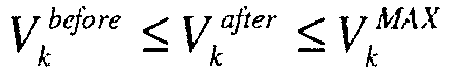
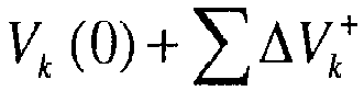
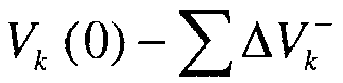
- One or more of the voltage magnitude constraints is disregarded for a particular node if a change in the discrete capacitor switch states (u c ) from one state (0 or 1) to the other state (1 or 0) and a change in the continuous DER set points (u der ) from the present value Q der (0) to the minimum or maximum limit Q der MIN or Q der MAX ) result in a cumulative voltage ( V k 0 + ⁇ ⁇ V k + or V k 0 ⁇ ⁇ V k ⁇ ) at that node within the predetermined minimum and/or maximum limits (V MAX / V MIN ) for that node.
- the maximum voltage magnitude constraint V k ⁇ V MAX for node k is disregarded if a change in the discrete capacitor switch states and a change in the continuous DER set points result in a cumulative voltage at node k which does not violate the predetermined maximum limit V MAX .
- the minimum voltage magnitude constraint V MIN ⁇ V k for node k is disregarded if a change in the discrete capacitor switch states and a change in the continuous DER set points result in a cumulative voltage at node k which does not violate the predetermined minimum limit V MIN .
- the power loss reduction embodiments described herein integrate DER reactive power control into a traditional capacitor control-based centralized network model-based online loss reduction solution to further facilitate reducing system loss, and are applicable to utility-scale distribution systems.
- An optimized coordination among multiple capacitors and DER reactive power control is implemented.
- the impact of capacitor and DER reactive power control on system node/bus voltage can be accounted for, and can include voltage constraints in the solution.
- Flexible voltage constraint representations allow utilities to reduce loss and/or correct voltage violation according to the requirement.
- the solution efficiency can be improved by disregarding noncritical constraints.
Description
- The instant application relates to power distribution systems, and more particularly to power loss reduction in such systems.
- Distributed energy resources (DERs), also commonly referred to as distributed generation, distributed energy, and distributed power systems, are small, modular, decentralized, grid-connected or off-grid energy systems located in or near the place where energy is used. DERs are integrated systems that can include effective means of power generation, energy storage, and delivery. DERs include systems such as reciprocating engines (diesel, natural gas, dual-fuel, etc.), combustion turbines, micro-turbines, fuel cells, photovoltaic systems, concentrating solar systems, wind energy systems, small modular biopower systems, energy storage systems (e.g. flywheels), etc.
- Many factors including environmental concerns, system expansion constraints, and technology enhancement in DERs have led to the progressive penetration of DERs in power distribution systems. DERs are able to provide energy at customer sites, and introduce new challenges in the optimization of power distribution system operation. In particular, many DERs have the capability to control their reactive power (var) output within a certain range, which offers new possibilities to control the reactive power flow in the electric power distribution network.
- Reactive power flow is needed in an alternating-current power distribution system to support the transfer of real power over the network. The portion of power flow that is temporarily stored in the form of magnetic or electric fields, due to inductive and capacitive network elements, and then returned to the source, is the reactive power. Inductive devices absorb reactive power from the network, and capacitive devices inject reactive power into the network. DERs can absorb or inject reactive power, depending on operating conditions. Inductive devices, capacitive devices and DERs connected to a power distribution network are referred to herein as reactive power resources. Energy stored in reactive power resources gives rise to reactive power flow. Reactive power flow strongly influences the voltage levels across the network. The voltage levels and reactive power flow must be carefully controlled to allow a power distribution system to operate within acceptable limits.
- In power distribution systems, power loss reduction is an important solution for improving system operation efficiency.
- A known solution can be found in the patent application N.
EP2397688A1 (Siemens AG) relates to an electric power control system and an electric power facility comprising the electric power control system. Moreover, another solution can be found in the Article of Kazaki H et Al "Voltage Regulation through Smart Utilization of Potential Reactive Power Resources" included in Computer Modeling and Simulation, 2011 Fifth UKSIM European Symposium on, IEEE, 16/11/2011 pages 293-298, XP032097535, and in the article of Zhu et Al. "Optimal distribution power flow for systems with distributed energy resources", International Journal ef electrical power & energy systems, Jordan Hill, Oxford, GBVol. 29, no. 3 13/01/2007, pages 260-267, XP005829695. - Power loss reduction involves the control of available reactive power resources to optimize the reactive power flow in the network. The predominant reactive power resources available in traditional power distribution systems are switchable shunt capacitor banks. Most conventional power loss reduction solutions therefore focus on the control of the capacitor banks only. However, with the increasing penetration of DERs in power distribution networks, additional reactive power resources are available other than just switched capacitor banks. Compared to the discrete control of capacitors, the continuous control capability of DERs can further facilitate power loss reduction. Conventional power loss reduction solutions that do consider DERs in the power loss reduction analysis are based on very simplified network models and are verifiable only for small systems. It is difficult to predict the effectiveness of such solutions on a realistic utility-scale system.
- The invention is defined by the features of the independent claims. Preferred embodiments are defined in the dependent claims. According to an aspect of embodiments described herein, DER reactive power control is integrated into a centralized power loss reduction framework for electric power distribution systems. The electric power distribution network control centers or the distribution system substations can therefore facilitate power loss reduction using DERs.
- According to an aspect of an embodiment of a method of power loss reduction in a power distribution system having a plurality of reactive power resources including capacitor banks and distributed energy resources connected to branches of the power distribution system, the method comprises: determining discrete switch states for the capacitor banks and continuous set points for the distributed energy resources so that the reactive power provided by the reactive power resources reduces power loss in the power distribution system when the capacitor banks are set in accordance with the respective discrete switch states and the distributed energy resources are operated at the respective continuous set points; and constraining a range of values for the continuous set points based on maximum and minimum reactive power limits for each distributed energy resource under consideration.
- According to a non-transitory computer-readable medium, the non-transitory computer-readable medium stores a computer program comprising program instructions to determine the discrete switch states for the capacitor banks and the continuous set points for the distributed energy resources, so that the reactive power provided by the reactive power resources reduces power loss in the power distribution system when the capacitor banks are set in accordance with the respective discrete switch states and the distributed energy resources are operated at the respective continuous set points. The computer program further comprises program instructions to constrain a range of values for the continuous set points based on maximum and minimum reactive power limits for each distributed energy resource under consideration.
- According to an aspect of an embodiment of a computer system configured to communicate with the power distribution system, the computer system comprises a processing circuit operable to determine the discrete switch states for the capacitor banks and the continuous set points for the distributed energy resources so that the reactive power provided by the reactive power resources reduces power loss in the power distribution system when the capacitor banks are set in accordance with the respective discrete switch states and the distributed energy resources are operated at the respective continuous set points. The processing circuit is further operable to constrain a range of values for the continuous set points based on maximum and minimum reactive power limits for each distributed energy resource under consideration.
- Those skilled in the art will recognize additional features and advantages upon reading the following detailed description, and upon viewing the accompanying drawings.
- The components in the figures are not necessarily to scale, emphasis instead being placed upon illustrating the principles of the invention. Moreover, in the figures, like reference numerals designate corresponding parts. In the drawings:
-
Figure 1 illustrates a schematic diagram of a power distribution system including a control system for implementing power loss reduction based on DER reactive power control. -
Figure 2 illustrates a flow diagram of an embodiment of a method of power loss reduction in a power distribution system based on DER reactive power control. -
Figure 1 illustrates a non-limiting exemplary embodiment of a power distribution system. The power distribution system has one ormore substations 100 and a plurality ofbranches 102 connected to the substation(s) 100 for distributing power over the network. The power distribution system also includes a plurality of reactive power resources, includingshunt capacitor banks 104 and distributed energy resources (DERs) 106 connected to thebranches 102 of the power distribution system. Only theNth capacitor bank 104, the Mth DER 106 and asingle substation 100 are shown inFigure 1 for ease of illustration only. In general, the power distribution system can include any suitable number ofsubstations 100,capacitor banks 102 and DERs 106. - The
DERs 106 are integrated systems that can include effective means of power generation, energy storage, and delivery. TheDERs 106 can include systems such as, but not limited to, reciprocating engines (diesel, natural gas, dual-fuel, etc.), combustion turbines, micro-turbines, fuel cells, photovoltaic systems, concentrating solar systems, wind energy systems, small modular biopower, energy storage systems (e.g. flywheels), etc.DERs 106 having controllable reactive power are utilized in a centralized power loss reduction framework implemented by the power distribution system. - To this end, the power distribution system includes a
central controller 108 for integrating the controllable DER reactive power into the centralized power loss reduction framework for the power distribution system. The power loss reduction framework achieves an optimized coordination amongmultiple capacitor banks 104 andDERs 106. The power loss reduction framework can also account for voltage correction by imposing node voltage constraints during the solution procedure. For example, flexible node voltage constraint representations can be introduced to meet different requirements from utilities. In addition, an approximate prescreening method is provided for excluding any noncritical node voltage constraints in order to improve the solution performance. - In more detail, the
central controller 108 monitors and controls operation of the power distribution system, including power loss reduction and voltage correction. Thecentral controller 108 can be connected to the power distribution system via a wired or wireless connection, as indicated by the dashed line connections shown inFigure 1 , or included in one of thesubstations 100. Thecentral controller 108 includes aprocessing circuit 110 which can include digital and/or analog circuitry, such as one or more controllers, processors, ASICs (application-specific integrated circuits), etc. for executing program code which implements network control functions including power loss reduction and voltage correction. To this end, thecentral controller 108 includes a powerloss reduction unit 112 included in or associated with theprocessing circuit 110 for implementing the power loss reduction and voltage correction procedures and corresponding calculations described herein. Thecentral controller 108 also hasmemory 114, such as DRAM (dynamic random access memory), and an HDD (hard disk drive) 116 for storing the program code and related data processed and accessed by theprocessing circuit 110 and powerloss reduction unit 112 during execution of the program code. Thecentral controller 108 also has I/O (input/output)circuitry 118 for sending and receiving information, including communicating discrete switch states for thecapacitor banks 104 to local controllers 120 of thecapacitor banks 104. The I/O circuitry 118 also communicates continuous set points for theDERs 106 tolocal controllers 122 of theDERs 106. The discrete capacitor switch states and the continuous DER set points control the reactive power output of thecapacitor banks 104 andDERs 106, respectively, and are determined as part of the power loss reduction framework as described in more detail later herein. - The
controllable DERs 106 have a reactive power (var) output which can be controlled within a certain range, via the respectivelocal controllers 122 connected to or integrated with theDERs 106. Thecentral controller 108 utilizes the controllable nature of the DER reactive power when implementing centralized power loss reduction and voltage correction in the power distribution system. Thecapacitor banks 104 offer two discrete states of reactive power - all or nothing - which can be switched into the network by correspondingswitches 124 under control of the respective local capacitor controller 120. The reactive power behavior of theNth capacitor bank 104 is graphically illustrated inFigure 1 , where the reactive power is plotted in kvar (kilo-var) as a function of time. The switch state of theNth capacitor bank 104 is changed at time t1, from OFF to ON, causing theNth capacitor bank 104 to provide its' full reactive power capacity to the power distribution network (grid). The switch state of theNth capacitor bank 104 is changed back to its previous state at time t2, from ON to OFF, removing the full reactive power capacity of theNth capacitor bank 104 from the network. - In contrast, the
controllable DERs 106 have continuous set points which yield a corresponding continuous reactive power response. Thecentral controller 108, via theprocessing circuit 110 and powerloss reduction unit 112, implements power loss reduction and voltage correction for the power distribution network in a more precise and accurate manner by accounting for and utilizing the continuous reactive power response of theDERs 106. - The capabilities of the
DERs 106 to control reactive power output may be different. For example,DERs 106 using asynchronous generators or line-communicated converter interfacing with the grid cannot control their reactive power output, whileDERs 106 using synchronous generators and self-commutated converters interfacing with the grid can be operated at any given power factor and therefore can be used to support reactive power. - Since power loss reduction is a steady state application in distribution management systems, only the steady state characteristics of the
DERs 106 are of most interest. A general steady-state DER model is therefore adopted. That is, for aDER 106 having controllable reactive power, its reactive power output can vary (injecting/absorbing) in a certain range. This range can be determined by the DER maximum capacity, preent real power output, and power factor limitation. More specifically, the following equations are used to calculate the maximum and minimum reactive power output for aDER 106 at a given time interval:


Pder : maximum DER active power output at the given time interval


Sder : DER maximum capacity - In equations (1) and (2), the maximum/minimum reactive power output of a
particular DER 106 at a given time interval does not result in an overload or power factor limitation violations. For some types ofDERs 106 such as solar and wind, the real power output may vary during the given time interval and therefore the maximum estimate, real power output should be used in the calculation. The maximum DER reactive power output is the minimum value of the two values determined by the lagging power factor limit


- Reactive power control of the
DERs 106 for power loss reduction and voltage correction is achieved based on an original power loss reduction framework, which is a centralized, detailed model-based online solution that optimizes the system reactive power flow by switching thecapacitor banks 104 while meeting branch current magnitude constraints. To integrate DER reactive power control, the original optimization formulation is augmented to include continuous DER reactive power control variables as described in more detail later herein with regard to equations (7) through (16). - The original power loss formulation without DER reactive power control is described in equations (3) through (6). Control variables used include the discrete capacitor switching control variables (uc) and continuous variables for real (d) and imaginary (q) branch current components


capacitor banks 104, e.g., uc = 0 or 1. The objective function represented by equation (3) is a quadratic power loss function. The power loss is calculated based on branch resistances (ri) and the real and imaginary branch currents


- In these equations, nb is the number of circuit branches (lines and transformer legs) in the power distribution system,


capacitor banks 104. The sensitivity values can be normalized by the perturbation size i.e. by the amount of reactive power provided by eachcapacitor bank 104 which can be switched in and out of the network by correspondingswitches 124 under control of the respective local capacitor controller 120. - The original power loss formulation is augmented to include DER reactive power control as additional continuous control variables. The augmented formulation also includes voltage magnitude constraints for different nodes of the power distribution system. The voltage constraints enable the formulation to account for voltage correction while reducing power loss. For example, voltage constraint representations can be introduced to meet different requirements from utilities. In addition, an approximate prescreening method is described in more detail later herein which excludes any noncritical voltage magnitude variables and constraints in the augmented optimization formulation in order to improve the solution performance. The augmented power loss reduction formulation with additional continuous DER reactive power control variables and voltage magnitude constraints is given by:


- The first part of the augmented power loss reduction formulation,

multiple capacitor banks 104 andDERs 106 while also implementing voltage correction by imposing voltage constraints during the solution procedure. - The power loss reduction objective function represented by equation (7) can be subject to the following linear branch current constraints:


- In equations (8) through (16),


capacitor banks 104 and the continuous set points change (uder) of theDERs 106,

capacitor banks 104 and the continuous set points change (uder) of theDERs 106, u represents the control variables for both the discrete switch states (uc) for thecapacitor banks 104 and the continuous set points (uder) for theDERs 106, nu is the number of total controllable variables (capacitor banks 104 andDERs 106 with controllable reactive power), and nder is the number ofcontrollable DERs 106. Also, Qder(0) is the reactive power output of theDERs 106 at the base case,
DERs 106 as given by equation (1),
DERs 106 as given by equation (2), Vk is the voltage magnitude at node k, Vk(0) is the present voltage magnitude at node k for the base case, VMAX is the voltage magnitude upper limit, and VMIN is the voltage magnitude lower limit. - Compared to the original formulation given by equation (3), the augmented formulation having the objective function given by equation (7) is modified to include voltage correction terms in accordance with the first part of equation (7),


DER 106 under consideration as given by equation (10). This way, more precise reactive power adjustments can be made by determining the appropriate continuous set points for theDERs 106, which in conjunction with the discrete capacitor switch states, more optimally reduce power loss within the power distribution system. According to the branch current constraints represented by equations (8) and (9) and the DER reactive power constraints represented by equation (10), the calculation of the original branch currents as given by equations (4) and (5) are extended to account for the impact of DER reactive power output change on the real and imaginary branch currents. -
Figure 2 illustrates an embodiment of a method of implementing the augmented power loss reduction formulation by thecentral controller 108 with support from the powerloss reduction unit 112. The discrete switch states for thecapacitor banks 104 and the continuous set points for theDERs 106 are determined in accordance with the first part of the augmented power loss reduction formulation,
capacitor banks 104 and DERs 106) reduces power loss in the power distribution system when thecapacitor banks 104 are set in accordance with the respective discrete switch states (0 or 1) and theDERs 106 are operated at the respective continuous set points (Block 200). - The range of continuous set points available for selection can be limited by equation (10). That is, the range of values for the DER continuous set points can be constrained to yield reactive power Qder (0) + uder within the maximum and minimum limits

DER 106 under consideration. In addition, the real and imaginary branch currents

capacitor banks 104 and DERs 106) on the real and imaginary branch currents as given by equations (8) and (9). - Power loss reduction are further limited to correct voltage violations based on voltage magnitude constraints for different nodes in the power distribution system in accordance with the second part of the augmented power loss reduction formulation,

- Power loss reduction optimization can be limited because of the voltage magnitude constraints so that a preexisting voltage magnitude violation at any of the nodes is not worsened as a result of the power loss reduction process, and no new voltage magnitude violations occur at any of the nodes as a result of the power loss reduction process. This way, utilities can accept the network voltage conditions regardless of violations before running the loss reduction application, and only require that the power loss reduction process not worsen the voltage profile. According to this embodiment, the objective is to reduce power loss while not making the existing voltage profile worse. For example, if a voltage violation alieady exists at a node prior to the power loss reduction process, then the process should not cause the voltage violation to worsen. If no voltage violation exists at a node, then the power loss reduction process should not introduce a new voltage violation at the node or any other node. Table 1 below illustrates three cases before and after the power loss reduction process is performed, where

Table 1. Before Loss Reduction After Loss Reduction Case 1 

Case 2 
Case 3 
- In another embodiment, the power loss reduction formulation can be limited because of the voltage magnitude constraints so that a preexisting voltage magnitude violation at any of the nodes is eliminated while performing the power loss reduction. This way, utilities can correct existing voltage violations while the power loss reduction process is performed and the voltage profile can be improved after the loss reduction process. As such, the first priority is to eliminate voltage violations. Power loss reduction is achieved only if the control actions for voltage correction and power loss reduction do not contradict to each other. The voltage constraints for this embodiment are represented by equation (17) below, which would replace the voltage constraints given by equations (12) through (14) in this particular embodiment:

- The introduction of voltage magnitude variables and related constraints increases the optimization problem dimension and complexity, which can influence the solution performance. The solution performance can be further optimized by disregarding noncritical voltage magnitude variables and constraints from the optimization function of equation (7).
- Noncritical voltage magnitude variables and constraints can be identified based on three factors. The first factor is the sensitivity value of the voltage magnitude (Vk) with respect to capacitor switching (


- Regarding the available control action for a
controllable capacitor bank 104, if the present capacitor bank status is on, then thatbank 104 can only be turned off, i.e., the available control actions (uc) is switching off (e.g. uc = -1). Otherwise, if the present capacitor bank status is off, then thebank 104 can only be turned on, i.e., the available control action for thiscapacitor bank 104 is switching on (uc = 1). - Regarding the available control action for the reactive power output of a
DER 106, the present DER reactive power output can be assumed to be Qder(0), and its maximum and minimum reactive power output limits are

DER 106 include increasing or decreasing its reactive power output. The sensitivity value of the voltage magnitude with respect to DER reactive power output change is positive (i.e., if DER reactive power output increases, then the voltage magnitude increases, and if DER reactive power output decreases, the voltage magnitude decreases). Thus when considering whether to increase/decrease the DER reactive power outputs to their maximum/minimum reactive power output limits (
- Described next is an embodiment of a process for disregarding noncritical voltage magnitude variables and constraints from the augmented power loss reduction formulation.
- Loop through all available control actions (uc and uder) for the
capacitor banks 104 and theDERs 106 as follows: - For each control action, loop through all node voltages:

- Then loop through all node voltages as follows:

- This prescreening procedure estimates the voltage magnitude under worst-case capacitor and DER control combination scenarios, i.e. each capacitor bank is on or off, and each DER is at its maximum (


- One or more of the voltage magnitude constraints is disregarded for a particular node if a change in the discrete capacitor switch states (uc) from one state (0 or 1) to the other state (1 or 0) and a change in the continuous DER set points (uder) from the present value Qder(0) to the minimum or maximum limit


- The power loss reduction embodiments described herein integrate DER reactive power control into a traditional capacitor control-based centralized network model-based online loss reduction solution to further facilitate reducing system loss, and are applicable to utility-scale distribution systems. An optimized coordination among multiple capacitors and DER reactive power control is implemented. The impact of capacitor and DER reactive power control on system node/bus voltage can be accounted for, and can include voltage constraints in the solution. Flexible voltage constraint representations allow utilities to reduce loss and/or correct voltage violation according to the requirement. The solution efficiency can be improved by disregarding noncritical constraints.
- Terms such as "first", "second", and the like, are used to describe various elements, regions, sections, etc. and are not intended to be limiting. Like terms refer to like elements throughout the description.
- As used herein, the terms "having", "containing", "including", "comprising" and the like are open ended terms that indicate the presence of stated elements or features, but do not preclude additional elements or features. The articles "a", "an" and "the" are intended to include the plural as well as the singular, unless the context clearly indicates otherwise.
- With the above range of variations and applications in mind, it should be understood that the present invention is not limited by the foregoing description, nor is it limited by the accompanying drawings. Instead, the present invention is limited only by the following claims and their legal equivalents.
Claims (14)
- A method of power loss reduction in a power distribution system having a plurality of reactive power resources (104, 124,120, 106, 122) including capacitor banks (104) and distributed energy resources (106) connected to branches (102) of the power distribution system the capacitor banks (104) having discrete switch states and the distributed energy resources (106) operating at continuous set points,
the method is characterised in that, that the method is comprising:simultaneously determining (200) discrete switch states for the capacitor banks (104) and continuous set points for the distributed energy resources (106) so that the reactive power provided by the reactive power resources reduces power loss in the power distribution system when the capacitor banks (104) are set in accordance with the respective discrete switch states and the distributed energy resources (106) are operated at the respective continuous set points;constraining (210) a range of values for the continuous set points based on maximum and minimum reactive power limits for each distributed energy resource (106) under consideration;controlling operation of the capacitor banks and the distributed energy resources based on the simultaneously determined discrete switch states for the capacitor banks and continuous set points for the distributed energy resources;correcting voltage magnitude violations based on voltage magnitude constraints for different nodes in the power distribution system,disregarding one or more of the voltage magnitude constraints for a node if a change in the discrete switch states from one state to another state for the capacitor banks (104) and a change in the continuous set points from a present value to the maximum or minimum reactive power limit for the distributed energy resources (106) result in a cumulative voltage at that node which is within predetermined minimum and maximum limits. - The method of claim 1, wherein the power loss in the power distribution system is reduced as a function of the discrete switch states for the capacitor banks (104), the continuous set points for the distributed energy resources (106), branch resistances, real branch currents, and imaginary branch currents, and wherein the real and imaginary branch currents account for the effect the reactive power provided by the reactive power resources has on the real and imaginary branch currents.
- The method of claim 1, wherein the voltage magnitude violations are corrected based on the voltage magnitude constraints so that a preexisting voltage magnitude violation at any of the nodes is not worsened as a result of the power loss reduction and no new voltage magnitude violations occur at any of the nodes as a result of the power loss reduction.
- The method of claim 1, wherein the voltage magnitude violations are corrected based on the voltage magnitude constraints so that a preexisting voltage magnitude violation at any of the nodes is eliminated while performing the power loss reduction.
- The method of claim 1, further comprising weighting the voltage magnitude constraints.
- The method of claim 5, wherein the voltage magnitude constraints for lower priority nodes are weighted less than the voltage magnitude constraints for higher priority nodes.
- The method of claim 1, wherein a maximum voltage magnitude constraint for a node is disregarded if the change in the discrete switch states for the capacitor banks (104) and the change in the continuous set points for the distributed energy resources (106) result in the cumulative voltage at that node not violating the predetermined maximum limit, and wherein a minimum voltage magnitude constraint for a node is disregarded if the change in the discrete switch states for the capacitor banks (104) and the change in the continuous set points for the distributed energy resources (106) result in the cumulative voltage at that node not violating the predetermined minimum limit.
- The method of claim 1, further comprising:communicating the discrete switch states for the capacitor banks (104) from a central controller (108) of the power distribution system to local controllers (120) of the capacitor banks (104) and;communicating the continuous set points for the distributed energy resources from the central controller (108) to local controllers (122) of the distributed energy resources (106).
- A computer system configured to communicate with a power distribution system (100, 102) having a plurality of reactive power resources (104, 124,120, 106, 122) including capacitor banks (104) and distributed energy resources (106) connected to branches (102) of the power distribution system, the capacitor banks (104) having discrete switch states and the distributed energy resources (106) operating at continuous set points, the computer system comprising a processing circuit (110) is characterised in that it is operable to:simultaneously determine discrete switch states for the capacitor banks (104) and continuous set points for the distributed energy resources (106) so that the reactive power provided by the reactive power resources reduces power loss in the power distribution system when the capacitor banks (104) are set in accordance with the respective discrete switch states and the distributed energy resources (106) are operated at the respective continuous set points;constrain a range of values for the continuous set points based on maximum and minimum reactive power limits for each distributed energy resource (106) under consideration;control operation (120, 122) of the capacitor banks and the distributed energy resources based on the simultaneously determined discrete switch states for the capacitor banks and continuous set points for the distributed energy resources;correct voltage magnitude violations based on voltage magnitude constraints for different nodes in the power distribution system,wherein the processing circuit (110) is further operable to disregard one or more of the voltage magnitude constraints for a node if a change in the discrete switch states from one state to another state for the capacitor banks (104) and a change in the continuous set points from a present value to the maximum or minimum reactive power limit for the distributed energy resources (106) result in a cumulative voltage at that node which is within predetermined minimum and maximum limits.
- The computer system of claim 9, wherein the processing circuit (110) is operable to correct the voltage magnitude violations based on the voltage magnitude constraints so that a preexisting voltage magnitude violation at any of the nodes is not worsened as a result of the power loss reduction and no new voltage magnitude violations occur at any of the nodes as a result of the power loss reduction.
- The computer system of claim 9, wherein the processing circuit (110) is operable to correct the voltage magnitude violations based on the voltage magnitude constraints so that a preexisting voltage magnitude violation at any of the nodes is eliminated while performing the power loss reduction.
- The computer system of claim 9, wherein the processing circuit (110) is further operable to weight the voltage magnitude constraints so that the voltage magnitude constraints for lower priority nodes are weighted less than the voltage magnitude constraints for higher priority nodes.
- The computer system of claim 9, wherein the processing circuit (110) is operable to disregard a maximum voltage magnitude constraint for a node if the change in the discrete switch states for the capacitor banks (104) and the change in the continuous set points for the distributed energy resources (106) result in the cumulative voltage at that node not violating the predetermined maximum limit, and wherein the processing circuit (110) is operable to disregard a minimum voltage magnitude constraint for a node if the change in the discrete switch states for the capacitor banks (104) and the change in the continuous set points for the distributed energy resources (106) result in the cumulative voltage at that node not violating the predetermined minimum limit.
- The computer system of claim 9, wherein the processing circuit (110) is further operable to communicate the discrete switch states for the capacitor banks (104) to local controllers (120) of the capacitor banks (104) and communicate the continuous set points for the distributed energy resources (106) to local controllers (122) of the distributed energy resources (106).
Applications Claiming Priority (2)
| Application Number | Priority Date | Filing Date | Title |
|---|---|---|---|
| US13/600,357 US9590423B2 (en) | 2012-08-31 | 2012-08-31 | Power distribution system loss reduction with distributed energy resource control |
| PCT/US2013/057196 WO2014036209A2 (en) | 2012-08-31 | 2013-08-29 | Power distribution system loss reduction with distributed energy resource control |
Publications (3)
| Publication Number | Publication Date |
|---|---|
| EP2891221A2 EP2891221A2 (en) | 2015-07-08 |
| EP2891221B1 EP2891221B1 (en) | 2017-06-14 |
| EP2891221B2 true EP2891221B2 (en) | 2024-02-28 |
Family
ID=49162254
Family Applications (1)
| Application Number | Title | Priority Date | Filing Date |
|---|---|---|---|
| EP13760196.9A Active EP2891221B2 (en) | 2012-08-31 | 2013-08-29 | Power distribution system loss reduction with distributed energy resource control |
Country Status (4)
| Country | Link |
|---|---|
| US (1) | US9590423B2 (en) |
| EP (1) | EP2891221B2 (en) |
| CN (1) | CN104584357B (en) |
| WO (1) | WO2014036209A2 (en) |
Families Citing this family (15)
| Publication number | Priority date | Publication date | Assignee | Title |
|---|---|---|---|---|
| EP2713463B1 (en) * | 2012-09-28 | 2018-06-13 | Enrichment Technology Company Ltd. | Energy storage system |
| US9553453B2 (en) | 2013-03-15 | 2017-01-24 | Dominion Resources, Inc. | Management of energy demand and energy efficiency savings from voltage optimization on electric power systems using AMI-based data analysis |
| CN103840467A (en) * | 2014-03-20 | 2014-06-04 | 武汉大学 | Reactive comprehensive control method based on improved five-zone diagram |
| WO2015180074A1 (en) * | 2014-05-28 | 2015-12-03 | Ge Energy Power Conversion Technology Ltd | Reactive power prediction capability |
| CN105046425B (en) * | 2015-07-03 | 2018-12-07 | 深圳供电局有限公司 | A kind of method and system of distributed energy resource system access power distribution network capability evaluation |
| CN110383201B (en) * | 2015-11-09 | 2022-01-18 | 日立能源瑞士股份公司 | Power equipment controller and power distribution system |
| US10148092B2 (en) | 2016-01-27 | 2018-12-04 | Alliance For Sustainable Energy, Llc | Real time voltage regulation through gather and broadcast techniques |
| US10516269B2 (en) | 2016-11-16 | 2019-12-24 | Alliance For Sustainable Energy, Llc | Real time feedback-based optimization of distributed energy resources |
| CN107069749B (en) * | 2017-03-20 | 2018-02-16 | 国网河北省电力公司 | The line disconnection method of Over High-Limit Voltage is eliminated under a kind of Spring Festival mode |
| CN108039720B (en) * | 2017-11-10 | 2021-09-03 | 中国电力科学研究院有限公司 | Method and device for determining maximum power transmission capacity of alternating current-direct current hybrid system |
| US10853084B2 (en) | 2019-02-13 | 2020-12-01 | Abb Schweiz Ag | System and method for coordinating resources |
| CN112713620B (en) * | 2020-11-23 | 2022-11-25 | 中国电力科学研究院有限公司 | Method and system for analyzing power transmission capacity of extra-high voltage alternating current-direct current coupling system |
| CN113162041A (en) * | 2021-04-29 | 2021-07-23 | 南方电网电力科技股份有限公司 | Monitoring method, device and equipment for optimizing line loss based on reactive correlation |
| CN113949063A (en) * | 2021-10-25 | 2022-01-18 | 国网天津市电力公司电力科学研究院 | Fault isolation and recovery reconstruction method for power distribution network |
| CN117517908B (en) * | 2024-01-08 | 2024-03-26 | 南京中鑫智电科技有限公司 | Insulating integrated monitoring system of full station capacitive equipment of transformer substation |
Family Cites Families (20)
| Publication number | Priority date | Publication date | Assignee | Title |
|---|---|---|---|---|
| US4365190A (en) | 1981-03-19 | 1982-12-21 | Asi Systems, Inc. | Automatic var controller |
| JPH0734624B2 (en) | 1987-09-21 | 1995-04-12 | 三菱電機株式会社 | Voltage-reactive power controller |
| US5081591A (en) | 1990-02-28 | 1992-01-14 | Westinghouse Electric Corp. | Optimizing reactive power distribution in an industrial power network |
| CN1022786C (en) * | 1992-05-25 | 1993-11-17 | 天津市荣发科技开发公司 | Self-adapting compensating-in-place method and apparatus thereof |
| US5422561A (en) | 1992-11-23 | 1995-06-06 | Southern California Edison Company | Automated voltage and VAR control in power transmission and distribution networks |
| US5541498A (en) | 1994-12-08 | 1996-07-30 | Beckwith; Robert W. | Distribution circuit var management system using adaptive capacitor controls |
| WO1997022169A2 (en) | 1995-11-30 | 1997-06-19 | Siemens Energy & Automation, Inc. | Voltage based var compensation system |
| US7343360B1 (en) * | 1998-05-13 | 2008-03-11 | Siemens Power Transmission & Distribution, Inc. | Exchange, scheduling and control system for electrical power |
| DE102004048341A1 (en) | 2004-10-01 | 2006-04-13 | Repower Systems Ag | Wind farm with robust reactive power regulation and method of operation |
| US7460931B2 (en) | 2005-10-07 | 2008-12-02 | Jay Jacobson | Method and system for improving the efficiency and reliability of a power grid |
| EP2362978B1 (en) | 2008-11-05 | 2013-01-02 | ABB Research Ltd. | Reactive power optimization |
| CN102204055B (en) | 2008-11-05 | 2014-11-05 | Abb研究有限公司 | Voltage regulation optimization |
| CN101420126A (en) * | 2008-11-21 | 2009-04-29 | 湖南大学 | Distribution network electric energy quality composite control system and controlling method thereof |
| US8874277B2 (en) * | 2009-09-15 | 2014-10-28 | Denis Kouroussis | Smart-grid adaptive power management method and system with power factor optimization and total harmonic distortion reduction |
| EP2580834B1 (en) | 2010-06-11 | 2019-12-18 | Siemens Aktiengesellschaft | Predictable feeding of reactive powers |
| EP2397688A1 (en) | 2010-06-16 | 2011-12-21 | Siemens Aktiengesellschaft | Electric power control system and electric power facility comprising the electric power control system |
| EP2397689A1 (en) | 2010-06-16 | 2011-12-21 | Siemens Aktiengesellschaft | Method and system for controlling a power production entity |
| US8664800B2 (en) | 2010-08-31 | 2014-03-04 | General Electric Company | System and method for distribution of inverter VAR support |
| US20120133209A1 (en) | 2010-11-30 | 2012-05-31 | General Electric Company | Integration of renewable power generating technologies with integrated volt/var control systems |
| CN102290818A (en) * | 2011-08-16 | 2011-12-21 | 辽宁省电力有限公司营口供电公司 | Automatic control system for reactive power of regional power grid |
-
2012
- 2012-08-31 US US13/600,357 patent/US9590423B2/en active Active
-
2013
- 2013-08-29 EP EP13760196.9A patent/EP2891221B2/en active Active
- 2013-08-29 WO PCT/US2013/057196 patent/WO2014036209A2/en active Application Filing
- 2013-08-29 CN CN201380043601.4A patent/CN104584357B/en active Active
Non-Patent Citations (1)
| Title |
|---|
| KIM D.H., LEE J.H., HONG S.H., KIM S.R.: "A mixed-integer programming approach for the linearized reactive power and voltage control-comparison with gradient projection approach", ENERGY MANAGEMENT AND POWER DELIVERY, 1998. PROCEEDINGS OF EMPD '98. 1 998 INTERNATIONAL CONFERENCE ON SINGAPORE 3-5 MARCH 1998, NEW YORK, NY, USA,IEEE, US, vol. 1, 3 March 1998 (1998-03-03) - 5 March 1998 (1998-03-05), US , pages 67 - 72, ISBN: 978-0-7803-4495-2, DOI: 10.1109/EMPD.1998.705422 † |
Also Published As
| Publication number | Publication date |
|---|---|
| CN104584357A (en) | 2015-04-29 |
| CN104584357B (en) | 2018-03-16 |
| WO2014036209A3 (en) | 2014-10-16 |
| EP2891221A2 (en) | 2015-07-08 |
| US20140062426A1 (en) | 2014-03-06 |
| WO2014036209A2 (en) | 2014-03-06 |
| US9590423B2 (en) | 2017-03-07 |
| EP2891221B1 (en) | 2017-06-14 |
Similar Documents
| Publication | Publication Date | Title |
|---|---|---|
| EP2891221B2 (en) | Power distribution system loss reduction with distributed energy resource control | |
| Kumar et al. | Recent philosophies of automatic generation control strategies in power systems | |
| Rahman et al. | Optimization of virtual inertia considering system frequency protection scheme | |
| Xiao et al. | Available transfer capability enhancement using FACTS devices | |
| KR101132107B1 (en) | System for controlling voltage and reactive power in electric power system connected with distributed generation and method for the same | |
| Amaris et al. | Reactive power management of power networks with wind generation | |
| Sarrias-Mena et al. | Fuzzy logic based power management strategy of a multi-MW doubly-fed induction generator wind turbine with battery and ultracapacitor | |
| Krishan et al. | Power management control strategy for hybrid energy storage system in a grid‐independent hybrid renewable energy system: a hardware‐in‐loop real‐time verification | |
| Bedawy et al. | An effective coordination strategy for voltage regulation in distribution system containing high intermittent photovoltaic penetrations | |
| CN102904266A (en) | Method for determining inactive compensation capacity network adaptability of wind power plant | |
| Xu et al. | Flexibility of variable-speed pumped-storage unit during primary frequency control and corresponding assessment method | |
| Rezaei et al. | Impacts of integration of very large‐scale photovoltaic power plants on rotor angle and frequency stability of power system | |
| Zhou et al. | Control strategy of DFIG and SVG cooperating to regulate grid voltage of wind power integration point | |
| Wang et al. | Coordinated multiple HVDC modulation emergency control for enhancing power system frequency stability | |
| Tapia‐Tinoco et al. | Hardware structures, control strategies, and applications of electric springs: a state‐of‐the‐art review | |
| Kazemzadeh et al. | STATCOM optimal allocation in transmission grids considering contingency analysis in OPF using BF-PSO algorithm | |
| CN113241753B (en) | Improved virtual generator control method for direct-current micro-grid | |
| CN115659098A (en) | Distributed new energy consumption capacity calculation method, device, equipment and medium | |
| Alatshan et al. | Application of static synchronous compensator and energy storage system for power system stability enhancement | |
| Liang et al. | Optimal control of battery for grid-connected wind-storage system | |
| Li et al. | Magnetically controllable reactor based multi-FACTS coordination control strategy | |
| Giraldo et al. | Optimal energy management of unbalanced three-phase grid-connected microgrids | |
| Zou et al. | Modeling for large-scale offshore wind farm using multi-thread parallel computing | |
| Castillo et al. | Optimal location and size for various renewable distributed generators in distribution networks | |
| Sangsarawut et al. | Optimal reactive power planning of doubly fed induction generators using genetic algorithms |
Legal Events
| Date | Code | Title | Description |
|---|---|---|---|
| PUAI | Public reference made under article 153(3) epc to a published international application that has entered the european phase |
Free format text: ORIGINAL CODE: 0009012 |
|
| 17P | Request for examination filed |
Effective date: 20150122 |
|
| AK | Designated contracting states |
Kind code of ref document: A2 Designated state(s): AL AT BE BG CH CY CZ DE DK EE ES FI FR GB GR HR HU IE IS IT LI LT LU LV MC MK MT NL NO PL PT RO RS SE SI SK SM TR |
|
| AX | Request for extension of the european patent |
Extension state: BA ME |
|
| RIN1 | Information on inventor provided before grant (corrected) |
Inventor name: YANG, FANG Inventor name: FENG, XIAOMING |
|
| DAX | Request for extension of the european patent (deleted) | ||
| 17Q | First examination report despatched |
Effective date: 20160602 |
|
| STAA | Information on the status of an ep patent application or granted ep patent |
Free format text: STATUS: EXAMINATION IS IN PROGRESS |
|
| GRAP | Despatch of communication of intention to grant a patent |
Free format text: ORIGINAL CODE: EPIDOSNIGR1 |
|
| STAA | Information on the status of an ep patent application or granted ep patent |
Free format text: STATUS: GRANT OF PATENT IS INTENDED |
|
| INTG | Intention to grant announced |
Effective date: 20170208 |
|
| GRAS | Grant fee paid |
Free format text: ORIGINAL CODE: EPIDOSNIGR3 |
|
| GRAA | (expected) grant |
Free format text: ORIGINAL CODE: 0009210 |
|
| STAA | Information on the status of an ep patent application or granted ep patent |
Free format text: STATUS: THE PATENT HAS BEEN GRANTED |
|
| AK | Designated contracting states |
Kind code of ref document: B1 Designated state(s): AL AT BE BG CH CY CZ DE DK EE ES FI FR GB GR HR HU IE IS IT LI LT LU LV MC MK MT NL NO PL PT RO RS SE SI SK SM TR |
|
| REG | Reference to a national code |
Ref country code: GB Ref legal event code: FG4D |
|
| REG | Reference to a national code |
Ref country code: CH Ref legal event code: EP Ref country code: AT Ref legal event code: REF Ref document number: 901808 Country of ref document: AT Kind code of ref document: T Effective date: 20170615 |
|
| REG | Reference to a national code |
Ref country code: IE Ref legal event code: FG4D |
|
| REG | Reference to a national code |
Ref country code: DE Ref legal event code: R096 Ref document number: 602013022285 Country of ref document: DE |
|
| REG | Reference to a national code |
Ref country code: NL Ref legal event code: MP Effective date: 20170614 |
|
| REG | Reference to a national code |
Ref country code: LT Ref legal event code: MG4D |
|
| PG25 | Lapsed in a contracting state [announced via postgrant information from national office to epo] |
Ref country code: LT Free format text: LAPSE BECAUSE OF FAILURE TO SUBMIT A TRANSLATION OF THE DESCRIPTION OR TO PAY THE FEE WITHIN THE PRESCRIBED TIME-LIMIT Effective date: 20170614 Ref country code: HR Free format text: LAPSE BECAUSE OF FAILURE TO SUBMIT A TRANSLATION OF THE DESCRIPTION OR TO PAY THE FEE WITHIN THE PRESCRIBED TIME-LIMIT Effective date: 20170614 Ref country code: FI Free format text: LAPSE BECAUSE OF FAILURE TO SUBMIT A TRANSLATION OF THE DESCRIPTION OR TO PAY THE FEE WITHIN THE PRESCRIBED TIME-LIMIT Effective date: 20170614 Ref country code: NO Free format text: LAPSE BECAUSE OF FAILURE TO SUBMIT A TRANSLATION OF THE DESCRIPTION OR TO PAY THE FEE WITHIN THE PRESCRIBED TIME-LIMIT Effective date: 20170914 Ref country code: GR Free format text: LAPSE BECAUSE OF FAILURE TO SUBMIT A TRANSLATION OF THE DESCRIPTION OR TO PAY THE FEE WITHIN THE PRESCRIBED TIME-LIMIT Effective date: 20170915 |
|
| REG | Reference to a national code |
Ref country code: AT Ref legal event code: MK05 Ref document number: 901808 Country of ref document: AT Kind code of ref document: T Effective date: 20170614 |
|
| PG25 | Lapsed in a contracting state [announced via postgrant information from national office to epo] |
Ref country code: RS Free format text: LAPSE BECAUSE OF FAILURE TO SUBMIT A TRANSLATION OF THE DESCRIPTION OR TO PAY THE FEE WITHIN THE PRESCRIBED TIME-LIMIT Effective date: 20170614 Ref country code: NL Free format text: LAPSE BECAUSE OF FAILURE TO SUBMIT A TRANSLATION OF THE DESCRIPTION OR TO PAY THE FEE WITHIN THE PRESCRIBED TIME-LIMIT Effective date: 20170614 Ref country code: BG Free format text: LAPSE BECAUSE OF FAILURE TO SUBMIT A TRANSLATION OF THE DESCRIPTION OR TO PAY THE FEE WITHIN THE PRESCRIBED TIME-LIMIT Effective date: 20170914 Ref country code: LV Free format text: LAPSE BECAUSE OF FAILURE TO SUBMIT A TRANSLATION OF THE DESCRIPTION OR TO PAY THE FEE WITHIN THE PRESCRIBED TIME-LIMIT Effective date: 20170614 Ref country code: SE Free format text: LAPSE BECAUSE OF FAILURE TO SUBMIT A TRANSLATION OF THE DESCRIPTION OR TO PAY THE FEE WITHIN THE PRESCRIBED TIME-LIMIT Effective date: 20170614 |
|
| PG25 | Lapsed in a contracting state [announced via postgrant information from national office to epo] |
Ref country code: EE Free format text: LAPSE BECAUSE OF FAILURE TO SUBMIT A TRANSLATION OF THE DESCRIPTION OR TO PAY THE FEE WITHIN THE PRESCRIBED TIME-LIMIT Effective date: 20170614 Ref country code: RO Free format text: LAPSE BECAUSE OF FAILURE TO SUBMIT A TRANSLATION OF THE DESCRIPTION OR TO PAY THE FEE WITHIN THE PRESCRIBED TIME-LIMIT Effective date: 20170614 Ref country code: AT Free format text: LAPSE BECAUSE OF FAILURE TO SUBMIT A TRANSLATION OF THE DESCRIPTION OR TO PAY THE FEE WITHIN THE PRESCRIBED TIME-LIMIT Effective date: 20170614 Ref country code: SK Free format text: LAPSE BECAUSE OF FAILURE TO SUBMIT A TRANSLATION OF THE DESCRIPTION OR TO PAY THE FEE WITHIN THE PRESCRIBED TIME-LIMIT Effective date: 20170614 Ref country code: CZ Free format text: LAPSE BECAUSE OF FAILURE TO SUBMIT A TRANSLATION OF THE DESCRIPTION OR TO PAY THE FEE WITHIN THE PRESCRIBED TIME-LIMIT Effective date: 20170614 |
|
| REG | Reference to a national code |
Ref country code: FR Ref legal event code: PLFP Year of fee payment: 5 |
|
| PG25 | Lapsed in a contracting state [announced via postgrant information from national office to epo] |
Ref country code: IS Free format text: LAPSE BECAUSE OF FAILURE TO SUBMIT A TRANSLATION OF THE DESCRIPTION OR TO PAY THE FEE WITHIN THE PRESCRIBED TIME-LIMIT Effective date: 20171014 Ref country code: PL Free format text: LAPSE BECAUSE OF FAILURE TO SUBMIT A TRANSLATION OF THE DESCRIPTION OR TO PAY THE FEE WITHIN THE PRESCRIBED TIME-LIMIT Effective date: 20170614 Ref country code: SM Free format text: LAPSE BECAUSE OF FAILURE TO SUBMIT A TRANSLATION OF THE DESCRIPTION OR TO PAY THE FEE WITHIN THE PRESCRIBED TIME-LIMIT Effective date: 20170614 Ref country code: ES Free format text: LAPSE BECAUSE OF FAILURE TO SUBMIT A TRANSLATION OF THE DESCRIPTION OR TO PAY THE FEE WITHIN THE PRESCRIBED TIME-LIMIT Effective date: 20170614 Ref country code: IT Free format text: LAPSE BECAUSE OF FAILURE TO SUBMIT A TRANSLATION OF THE DESCRIPTION OR TO PAY THE FEE WITHIN THE PRESCRIBED TIME-LIMIT Effective date: 20170614 |
|
| REG | Reference to a national code |
Ref country code: DE Ref legal event code: R026 Ref document number: 602013022285 Country of ref document: DE |
|
| PLBI | Opposition filed |
Free format text: ORIGINAL CODE: 0009260 |
|
| REG | Reference to a national code |
Ref country code: CH Ref legal event code: PL |
|
| PG25 | Lapsed in a contracting state [announced via postgrant information from national office to epo] |
Ref country code: MC Free format text: LAPSE BECAUSE OF FAILURE TO SUBMIT A TRANSLATION OF THE DESCRIPTION OR TO PAY THE FEE WITHIN THE PRESCRIBED TIME-LIMIT Effective date: 20170614 |
|
| PLAX | Notice of opposition and request to file observation + time limit sent |
Free format text: ORIGINAL CODE: EPIDOSNOBS2 |
|
| 26 | Opposition filed |
Opponent name: SIEMENS AKTIENGESELLSCHAFT Effective date: 20180314 |
|
| PG25 | Lapsed in a contracting state [announced via postgrant information from national office to epo] |
Ref country code: CH Free format text: LAPSE BECAUSE OF NON-PAYMENT OF DUE FEES Effective date: 20170831 Ref country code: LI Free format text: LAPSE BECAUSE OF NON-PAYMENT OF DUE FEES Effective date: 20170831 Ref country code: DK Free format text: LAPSE BECAUSE OF FAILURE TO SUBMIT A TRANSLATION OF THE DESCRIPTION OR TO PAY THE FEE WITHIN THE PRESCRIBED TIME-LIMIT Effective date: 20170614 |
|
| GBPC | Gb: european patent ceased through non-payment of renewal fee |
Effective date: 20170914 |
|
| REG | Reference to a national code |
Ref country code: IE Ref legal event code: MM4A |
|
| REG | Reference to a national code |
Ref country code: BE Ref legal event code: MM Effective date: 20170831 |
|
| PG25 | Lapsed in a contracting state [announced via postgrant information from national office to epo] |
Ref country code: LU Free format text: LAPSE BECAUSE OF NON-PAYMENT OF DUE FEES Effective date: 20170829 |
|
| PG25 | Lapsed in a contracting state [announced via postgrant information from national office to epo] |
Ref country code: GB Free format text: LAPSE BECAUSE OF NON-PAYMENT OF DUE FEES Effective date: 20170914 Ref country code: IE Free format text: LAPSE BECAUSE OF NON-PAYMENT OF DUE FEES Effective date: 20170829 |
|
| PLBB | Reply of patent proprietor to notice(s) of opposition received |
Free format text: ORIGINAL CODE: EPIDOSNOBS3 |
|
| PG25 | Lapsed in a contracting state [announced via postgrant information from national office to epo] |
Ref country code: SI Free format text: LAPSE BECAUSE OF FAILURE TO SUBMIT A TRANSLATION OF THE DESCRIPTION OR TO PAY THE FEE WITHIN THE PRESCRIBED TIME-LIMIT Effective date: 20170614 Ref country code: BE Free format text: LAPSE BECAUSE OF NON-PAYMENT OF DUE FEES Effective date: 20170831 |
|
| PG25 | Lapsed in a contracting state [announced via postgrant information from national office to epo] |
Ref country code: MT Free format text: LAPSE BECAUSE OF NON-PAYMENT OF DUE FEES Effective date: 20170829 |
|
| PG25 | Lapsed in a contracting state [announced via postgrant information from national office to epo] |
Ref country code: HU Free format text: LAPSE BECAUSE OF FAILURE TO SUBMIT A TRANSLATION OF THE DESCRIPTION OR TO PAY THE FEE WITHIN THE PRESCRIBED TIME-LIMIT; INVALID AB INITIO Effective date: 20130829 |
|
| RAP2 | Party data changed (patent owner data changed or rights of a patent transferred) |
Owner name: ABB SCHWEIZ AG |
|
| PG25 | Lapsed in a contracting state [announced via postgrant information from national office to epo] |
Ref country code: CY Free format text: LAPSE BECAUSE OF FAILURE TO SUBMIT A TRANSLATION OF THE DESCRIPTION OR TO PAY THE FEE WITHIN THE PRESCRIBED TIME-LIMIT Effective date: 20170614 |
|
| REG | Reference to a national code |
Ref country code: DE Ref legal event code: R081 Ref document number: 602013022285 Country of ref document: DE Owner name: HITACHI ENERGY SWITZERLAND AG, CH Free format text: FORMER OWNER: ABB RESEARCH LTD., ZUERICH, CH Ref country code: DE Ref legal event code: R082 Ref document number: 602013022285 Country of ref document: DE Representative=s name: STOLMAR & PARTNER PATENTANWAELTE PARTG MBB, DE Ref country code: DE Ref legal event code: R081 Ref document number: 602013022285 Country of ref document: DE Owner name: ABB SCHWEIZ AG, CH Free format text: FORMER OWNER: ABB RESEARCH LTD., ZUERICH, CH Ref country code: DE Ref legal event code: R081 Ref document number: 602013022285 Country of ref document: DE Owner name: ABB POWER GRIDS SWITZERLAND AG, CH Free format text: FORMER OWNER: ABB RESEARCH LTD., ZUERICH, CH Ref country code: DE Ref legal event code: R082 Ref document number: 602013022285 Country of ref document: DE Representative=s name: DENNEMEYER & ASSOCIATES S.A., DE |
|
| PG25 | Lapsed in a contracting state [announced via postgrant information from national office to epo] |
Ref country code: MK Free format text: LAPSE BECAUSE OF FAILURE TO SUBMIT A TRANSLATION OF THE DESCRIPTION OR TO PAY THE FEE WITHIN THE PRESCRIBED TIME-LIMIT Effective date: 20170614 |
|
| APBM | Appeal reference recorded |
Free format text: ORIGINAL CODE: EPIDOSNREFNO |
|
| APBP | Date of receipt of notice of appeal recorded |
Free format text: ORIGINAL CODE: EPIDOSNNOA2O |
|
| APAH | Appeal reference modified |
Free format text: ORIGINAL CODE: EPIDOSCREFNO |
|
| PG25 | Lapsed in a contracting state [announced via postgrant information from national office to epo] |
Ref country code: TR Free format text: LAPSE BECAUSE OF FAILURE TO SUBMIT A TRANSLATION OF THE DESCRIPTION OR TO PAY THE FEE WITHIN THE PRESCRIBED TIME-LIMIT Effective date: 20170614 |
|
| RAP2 | Party data changed (patent owner data changed or rights of a patent transferred) |
Owner name: ABB POWER GRIDS SWITZERLAND AG |
|
| APBQ | Date of receipt of statement of grounds of appeal recorded |
Free format text: ORIGINAL CODE: EPIDOSNNOA3O |
|
| PG25 | Lapsed in a contracting state [announced via postgrant information from national office to epo] |
Ref country code: PT Free format text: LAPSE BECAUSE OF FAILURE TO SUBMIT A TRANSLATION OF THE DESCRIPTION OR TO PAY THE FEE WITHIN THE PRESCRIBED TIME-LIMIT Effective date: 20170614 |
|
| PG25 | Lapsed in a contracting state [announced via postgrant information from national office to epo] |
Ref country code: AL Free format text: LAPSE BECAUSE OF FAILURE TO SUBMIT A TRANSLATION OF THE DESCRIPTION OR TO PAY THE FEE WITHIN THE PRESCRIBED TIME-LIMIT Effective date: 20170614 |
|
| REG | Reference to a national code |
Ref country code: DE Ref legal event code: R081 Ref document number: 602013022285 Country of ref document: DE Owner name: HITACHI ENERGY SWITZERLAND AG, CH Free format text: FORMER OWNER: ABB SCHWEIZ AG, BADEN, CH Ref country code: DE Ref legal event code: R081 Ref document number: 602013022285 Country of ref document: DE Owner name: HITACHI ENERGY LTD, CH Free format text: FORMER OWNER: ABB SCHWEIZ AG, BADEN, CH Ref country code: DE Ref legal event code: R082 Ref document number: 602013022285 Country of ref document: DE Representative=s name: DENNEMEYER & ASSOCIATES S.A., DE Ref country code: DE Ref legal event code: R081 Ref document number: 602013022285 Country of ref document: DE Owner name: ABB POWER GRIDS SWITZERLAND AG, CH Free format text: FORMER OWNER: ABB SCHWEIZ AG, BADEN, CH |
|
| RAP4 | Party data changed (patent owner data changed or rights of a patent transferred) |
Owner name: HITACHI ENERGY SWITZERLAND AG |
|
| REG | Reference to a national code |
Ref country code: DE Ref legal event code: R081 Ref document number: 602013022285 Country of ref document: DE Owner name: HITACHI ENERGY SWITZERLAND AG, CH Free format text: FORMER OWNER: ABB POWER GRIDS SWITZERLAND AG, BADEN, CH Ref country code: DE Ref legal event code: R081 Ref document number: 602013022285 Country of ref document: DE Owner name: HITACHI ENERGY LTD, CH Free format text: FORMER OWNER: ABB POWER GRIDS SWITZERLAND AG, BADEN, CH |
|
| PLAB | Opposition data, opponent's data or that of the opponent's representative modified |
Free format text: ORIGINAL CODE: 0009299OPPO |
|
| R26 | Opposition filed (corrected) |
Opponent name: SIEMENS AKTIENGESELLSCHAFT Effective date: 20180314 |
|
| P01 | Opt-out of the competence of the unified patent court (upc) registered |
Effective date: 20230527 |
|
| APBU | Appeal procedure closed |
Free format text: ORIGINAL CODE: EPIDOSNNOA9O |
|
| RIN2 | Information on inventor provided after grant (corrected) |
Inventor name: FENG, XIAOMING Inventor name: YANG, FANG |
|
| PGFP | Annual fee paid to national office [announced via postgrant information from national office to epo] |
Ref country code: FR Payment date: 20230824 Year of fee payment: 11 Ref country code: DE Payment date: 20230821 Year of fee payment: 11 |
|
| PUAH | Patent maintained in amended form |
Free format text: ORIGINAL CODE: 0009272 |
|
| STAA | Information on the status of an ep patent application or granted ep patent |
Free format text: STATUS: PATENT MAINTAINED AS AMENDED |
|
| 27A | Patent maintained in amended form |
Effective date: 20240228 |
|
| AK | Designated contracting states |
Kind code of ref document: B2 Designated state(s): AL AT BE BG CH CY CZ DE DK EE ES FI FR GB GR HR HU IE IS IT LI LT LU LV MC MK MT NL NO PL PT RO RS SE SI SK SM TR |
|
| REG | Reference to a national code |
Ref country code: DE Ref legal event code: R102 Ref document number: 602013022285 Country of ref document: DE |
|
| REG | Reference to a national code |
Ref country code: DE Ref legal event code: R082 Ref document number: 602013022285 Country of ref document: DE Representative=s name: DENNEMEYER & ASSOCIATES S.A., DE Ref country code: DE Ref legal event code: R081 Ref document number: 602013022285 Country of ref document: DE Owner name: HITACHI ENERGY LTD, CH Free format text: FORMER OWNER: HITACHI ENERGY SWITZERLAND AG, BADEN, CH |