EP2890463B1 - Appareil d'échappement électrique pour un dispositif respiratoire de protection personnelle - Google Patents
Appareil d'échappement électrique pour un dispositif respiratoire de protection personnelle Download PDFInfo
- Publication number
- EP2890463B1 EP2890463B1 EP13752764.4A EP13752764A EP2890463B1 EP 2890463 B1 EP2890463 B1 EP 2890463B1 EP 13752764 A EP13752764 A EP 13752764A EP 2890463 B1 EP2890463 B1 EP 2890463B1
- Authority
- EP
- European Patent Office
- Prior art keywords
- exhaust apparatus
- wearer
- personal protection
- respiratory device
- respirator
- Prior art date
- Legal status (The legal status is an assumption and is not a legal conclusion. Google has not performed a legal analysis and makes no representation as to the accuracy of the status listed.)
- Active
Links
- 230000000241 respiratory effect Effects 0.000 title claims description 57
- 230000029058 respiratory gaseous exchange Effects 0.000 claims description 21
- 230000007246 mechanism Effects 0.000 claims description 8
- 239000012530 fluid Substances 0.000 claims 2
- 239000003570 air Substances 0.000 description 63
- CURLTUGMZLYLDI-UHFFFAOYSA-N Carbon dioxide Chemical compound O=C=O CURLTUGMZLYLDI-UHFFFAOYSA-N 0.000 description 28
- 238000001914 filtration Methods 0.000 description 28
- 238000012360 testing method Methods 0.000 description 19
- 238000001816 cooling Methods 0.000 description 15
- 229910002092 carbon dioxide Inorganic materials 0.000 description 14
- 239000001569 carbon dioxide Substances 0.000 description 14
- 230000000694 effects Effects 0.000 description 14
- 239000007789 gas Substances 0.000 description 9
- 230000008901 benefit Effects 0.000 description 6
- 238000005259 measurement Methods 0.000 description 6
- 230000009467 reduction Effects 0.000 description 6
- 239000012080 ambient air Substances 0.000 description 4
- 230000007613 environmental effect Effects 0.000 description 4
- 210000000481 breast Anatomy 0.000 description 3
- 239000000356 contaminant Substances 0.000 description 3
- 238000013461 design Methods 0.000 description 2
- 239000002245 particle Substances 0.000 description 2
- 230000000276 sedentary effect Effects 0.000 description 2
- 230000000007 visual effect Effects 0.000 description 2
- OKTJSMMVPCPJKN-UHFFFAOYSA-N Carbon Chemical compound [C] OKTJSMMVPCPJKN-UHFFFAOYSA-N 0.000 description 1
- 238000013459 approach Methods 0.000 description 1
- 229910052799 carbon Inorganic materials 0.000 description 1
- 230000008859 change Effects 0.000 description 1
- 230000000295 complement effect Effects 0.000 description 1
- 230000001276 controlling effect Effects 0.000 description 1
- 230000001419 dependent effect Effects 0.000 description 1
- 238000011161 development Methods 0.000 description 1
- 238000010586 diagram Methods 0.000 description 1
- 239000004744 fabric Substances 0.000 description 1
- 239000000383 hazardous chemical Substances 0.000 description 1
- 239000002085 irritant Substances 0.000 description 1
- 231100000021 irritant Toxicity 0.000 description 1
- 239000000463 material Substances 0.000 description 1
- 230000001473 noxious effect Effects 0.000 description 1
- 230000001681 protective effect Effects 0.000 description 1
- 230000001105 regulatory effect Effects 0.000 description 1
- 238000004088 simulation Methods 0.000 description 1
- XLYOFNOQVPJJNP-UHFFFAOYSA-N water Substances O XLYOFNOQVPJJNP-UHFFFAOYSA-N 0.000 description 1
Images


Classifications
-
- A—HUMAN NECESSITIES
- A62—LIFE-SAVING; FIRE-FIGHTING
- A62B—DEVICES, APPARATUS OR METHODS FOR LIFE-SAVING
- A62B23/00—Filters for breathing-protection purposes
- A62B23/02—Filters for breathing-protection purposes for respirators
- A62B23/025—Filters for breathing-protection purposes for respirators the filter having substantially the shape of a mask
-
- A—HUMAN NECESSITIES
- A61—MEDICAL OR VETERINARY SCIENCE; HYGIENE
- A61M—DEVICES FOR INTRODUCING MEDIA INTO, OR ONTO, THE BODY; DEVICES FOR TRANSDUCING BODY MEDIA OR FOR TAKING MEDIA FROM THE BODY; DEVICES FOR PRODUCING OR ENDING SLEEP OR STUPOR
- A61M16/00—Devices for influencing the respiratory system of patients by gas treatment, e.g. mouth-to-mouth respiration; Tracheal tubes
- A61M16/10—Preparation of respiratory gases or vapours
- A61M16/105—Filters
- A61M16/106—Filters in a path
-
- A—HUMAN NECESSITIES
- A62—LIFE-SAVING; FIRE-FIGHTING
- A62B—DEVICES, APPARATUS OR METHODS FOR LIFE-SAVING
- A62B18/00—Breathing masks or helmets, e.g. affording protection against chemical agents or for use at high altitudes or incorporating a pump or compressor for reducing the inhalation effort
- A62B18/006—Breathing masks or helmets, e.g. affording protection against chemical agents or for use at high altitudes or incorporating a pump or compressor for reducing the inhalation effort with pumps for forced ventilation
-
- A—HUMAN NECESSITIES
- A62—LIFE-SAVING; FIRE-FIGHTING
- A62B—DEVICES, APPARATUS OR METHODS FOR LIFE-SAVING
- A62B18/00—Breathing masks or helmets, e.g. affording protection against chemical agents or for use at high altitudes or incorporating a pump or compressor for reducing the inhalation effort
- A62B18/02—Masks
-
- A—HUMAN NECESSITIES
- A62—LIFE-SAVING; FIRE-FIGHTING
- A62B—DEVICES, APPARATUS OR METHODS FOR LIFE-SAVING
- A62B18/00—Breathing masks or helmets, e.g. affording protection against chemical agents or for use at high altitudes or incorporating a pump or compressor for reducing the inhalation effort
- A62B18/08—Component parts for gas-masks or gas-helmets, e.g. windows, straps, speech transmitters, signal-devices
- A62B18/10—Valves
-
- A—HUMAN NECESSITIES
- A62—LIFE-SAVING; FIRE-FIGHTING
- A62B—DEVICES, APPARATUS OR METHODS FOR LIFE-SAVING
- A62B7/00—Respiratory apparatus
-
- A—HUMAN NECESSITIES
- A62—LIFE-SAVING; FIRE-FIGHTING
- A62B—DEVICES, APPARATUS OR METHODS FOR LIFE-SAVING
- A62B7/00—Respiratory apparatus
- A62B7/10—Respiratory apparatus with filter elements
-
- A—HUMAN NECESSITIES
- A61—MEDICAL OR VETERINARY SCIENCE; HYGIENE
- A61M—DEVICES FOR INTRODUCING MEDIA INTO, OR ONTO, THE BODY; DEVICES FOR TRANSDUCING BODY MEDIA OR FOR TAKING MEDIA FROM THE BODY; DEVICES FOR PRODUCING OR ENDING SLEEP OR STUPOR
- A61M16/00—Devices for influencing the respiratory system of patients by gas treatment, e.g. mouth-to-mouth respiration; Tracheal tubes
- A61M16/0057—Pumps therefor
- A61M16/0066—Blowers or centrifugal pumps
-
- A—HUMAN NECESSITIES
- A61—MEDICAL OR VETERINARY SCIENCE; HYGIENE
- A61M—DEVICES FOR INTRODUCING MEDIA INTO, OR ONTO, THE BODY; DEVICES FOR TRANSDUCING BODY MEDIA OR FOR TAKING MEDIA FROM THE BODY; DEVICES FOR PRODUCING OR ENDING SLEEP OR STUPOR
- A61M16/00—Devices for influencing the respiratory system of patients by gas treatment, e.g. mouth-to-mouth respiration; Tracheal tubes
- A61M16/10—Preparation of respiratory gases or vapours
-
- A—HUMAN NECESSITIES
- A61—MEDICAL OR VETERINARY SCIENCE; HYGIENE
- A61M—DEVICES FOR INTRODUCING MEDIA INTO, OR ONTO, THE BODY; DEVICES FOR TRANSDUCING BODY MEDIA OR FOR TAKING MEDIA FROM THE BODY; DEVICES FOR PRODUCING OR ENDING SLEEP OR STUPOR
- A61M2205/00—General characteristics of the apparatus
- A61M2205/50—General characteristics of the apparatus with microprocessors or computers
- A61M2205/502—User interfaces, e.g. screens or keyboards
-
- A—HUMAN NECESSITIES
- A61—MEDICAL OR VETERINARY SCIENCE; HYGIENE
- A61M—DEVICES FOR INTRODUCING MEDIA INTO, OR ONTO, THE BODY; DEVICES FOR TRANSDUCING BODY MEDIA OR FOR TAKING MEDIA FROM THE BODY; DEVICES FOR PRODUCING OR ENDING SLEEP OR STUPOR
- A61M2205/00—General characteristics of the apparatus
- A61M2205/82—Internal energy supply devices
- A61M2205/8206—Internal energy supply devices battery-operated
-
- A—HUMAN NECESSITIES
- A62—LIFE-SAVING; FIRE-FIGHTING
- A62B—DEVICES, APPARATUS OR METHODS FOR LIFE-SAVING
- A62B18/00—Breathing masks or helmets, e.g. affording protection against chemical agents or for use at high altitudes or incorporating a pump or compressor for reducing the inhalation effort
- A62B18/003—Breathing masks or helmets, e.g. affording protection against chemical agents or for use at high altitudes or incorporating a pump or compressor for reducing the inhalation effort having means for creating a fresh air curtain
-
- A—HUMAN NECESSITIES
- A62—LIFE-SAVING; FIRE-FIGHTING
- A62B—DEVICES, APPARATUS OR METHODS FOR LIFE-SAVING
- A62B9/00—Component parts for respiratory or breathing apparatus
- A62B9/02—Valves
Definitions
- the present invention relates to an exhaust apparatus for personal protection respiratory devices, particularly negative pressure respirators.
- the present invention relates to a powered exhaust apparatus which can be releasably connected to a personal protection respiratory device.
- the powered exhaust apparatus removes the hot and moist air that can often build-up inside a negative pressure respirator to significantly improve and enhance wearer comfort.
- Negative pressure respirators are well known in the art. With respirators of this type, filtered air is drawn into the enclosed space between the inside of the respirator and a wearer's face through a filter system by the wearer's breathing action. When the wearer draws a breath, negative pressure is created in the respirator and air is drawn in through the filter system. When the wearer exhales a breath, spent air leaves the respirator through an exhalation valve and/or back through the filter system.
- US6257235 discloses a face mask is provided having a filter body sized to cover the nose and mouth of a wearer, a securing mechanism for holding the filter body in close fit with the wearer's face, and a fan attachment to enhance breathability and comfort of the mask
- WO9005565 discloses a protective hood for use either in fire emergencies or as protection against escaping irritant gases in an industrial environment.
- the hood is fitted with at least one motor-driven fan to assist in removal of accumulating exhaled gases within the hood and with power means to drive the motor, the fan and the power means being arranged in the hood in such manner that power is supplied to the motor automatically when the hood is unpacked or first donned.
- An advantage of using an exhaust apparatus for releasable connection to a personal protection respiratory device is that it improves the comfort and overall experience for the wearer regardless of the intensity of the work being undertaken. The benefit is noticeable as soon as the blower is operated, even if the wearer is undertaking a low intensity task.
- Use of the present invention especially allows the respirator to be worn for intensive work, and/or for long periods of time, and/or in hot and humid environmental conditions by removing the heat and moisture build-up inside the respirator.
- the use of a powered exhaust apparatus which draws the hot air and moisture out of the enclosed space between the inside of the respirator and the wearer, means that the difficulties sometimes experienced in hot and humid conditions or after extended periods of use are minimized or removed completely.
- the act of drawing the hot and moist air out of the respirator and replacing it with fresh un-breathed filtered air also makes breathing easier for the wearer. This is because the first portion of the next breath of the wearer is fresh un-breathed filtered air, rather than the last portion of the previously exhaled breath. Since the present invention draws more air out of the respirator than wearer exhales, the difference is fresh air drawn in through filters. This also gives improvements in terms of the carbon dioxide levels inside the respirator.
- the exhaust apparatus may further comprise an attachment means for releasably connecting the blower to the at least one exhalation valve.
- attachment means is selected from a group consisting of interference fit, screw thread, snap fit engagement, bayonet, quick release mechanism, slider and groove engagement, locking pin, locking clip and mechanical hook and loop fastener.
- the personal protection respiratory device is selected from a group consisting of disposable, reusable, half mask, full face, particulate, gas and vapour and tight-fitting hood respirators.
- the blower may further be operable at a volumetric flow rate of between 0 to 180 litres per minute.
- the blower is operable to reduce the pressure inside the personal protection respiratory device by at least 150 Pa at the peak exhalation flow rate of the wearer.
- blower is operable to reduce the temperature inside the personal protection respiratory device by at least about 1°C to 3°C.
- the blower may further be operable to reduce the rebreathed carbon dioxide level inside the personal protection respiratory device by up to about 0.7%.
- the exhaust apparatus may further comprise a portable power supply for the blower, the portable power supply being integrally mounted with the blower.
- the exhaust apparatus further comprises a portable power supply for the blower, the portable power supply being remotely positionable on the wearer.
- the present invention has adopted the approach of using an exhaust apparatus for releasable or permanent connection to a personal protection respiratory device such that it improves the comfort and overall experience for the wearer.
- Use of the present invention allows the respirator to be worn for intensive work, and/or for long periods of time, and/or in hot and humid environmental conditions by removing the heat and moisture build-up inside the respirator.
- the benefit felt by the wearer occurs both at very low work rates, e.g. whilst performing sedentary tasks, but the effect can also be increased as work rate increases.
- the use of a powered exhaust apparatus which draws the hot air and moisture out of the enclosed space between the inside of the respirator and the wearer, means that the difficulties sometimes experienced in hot and humid conditions or after extended periods of use are minimized or removed completely.
- the act of drawing the hot and moist air out of the respirator and replacing it with fresh un-breathed air also makes breathing easier for the wearer. This is because the first portion of the next breath of the wearer is fresh un-breathed air, rather than the last portion of the previously exhaled breath. This also gives improvements in terms of the carbon dioxide levels inside the respirator.
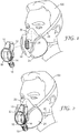
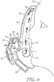
- FIG 1 is an exploded view of an exhaust apparatus 10 which is able to releasably connect or engage with a personal protection respiratory device 20.
- respirator 20 that is illustrated in Figures 1, 2 , 4 , 5, 6 , 8 and 9 is indicative of the 3MTM 4000 Series of gas, vapor and particulate respirators
- the exhaust apparatus 10 can be utilized with any negative pressure respiratory device 20.
- respirator or "respiratory mask”, as used interchangeably herein, is intended to mean a breathing device worn to prevent the inhalation of hazardous substances, particles, vapors or noxious gases.
- negative pressure respiratory mask is intended to cover any respirator in which the air pressure inside the mask becomes lower than the ambient air pressure when the wearer inhales.
- a negative pressure respiratory mask 20 as described herein is used to mean any form of respirator intended to fit the face of the wearer 100 in a substantially sealed configuration causing the air inhaled and exhaled by the wearer 100 to pass through a filter body or a filter portion of the respirator.
- Negative pressure respiratory mask 20 can also be a full or half facepiece mask, depending upon the hazard of concern. Again, these masks utilize a filter which prevents the inhalation of contaminants, particles, gases and vapors from the air inhaled by the wearer.
- Some common examples of this type of respirator are manufactured by 3M Company located in St. Paul, Minnesota, and include the 3MTM 6000 and 7000 Series of reusable respirators or tight-fitting hood facepiece respirators.
- Disposable respirators such as the 3MTM 8000 and 9000 Series of cup-shaped and flat-folded products, are lightweight single-piece respirators that employ a filter media which removes particulates and mists from the air stream as the wearer draws a breath. The entire unit is designed to be discarded after some extended period or a single use or single shift, depending on the contaminant.
- Filtering facepieces such as the 3MTM 6000 and 7000 Series are generally reusable products and which can have replaceable filter cartridges. Typically one or two cartridges attach securely to half mask or full facepiece which has built into it a corresponding number of valves for inhalation, and usually one for exhalation.
- the personal protection respiratory device 20 that is illustrated in Figure 1 is a 3MTM 4251 Valved Filtering Half Face Respirator. As shown in Figure 1 , a pair of filter cartridges 22, 24 are integrally attached to the respirator mask 20 at respective inhalation ports (not shown). Each of the inhalation ports having a respective inhalation valve (not shown) on the inside of the respirator mask 20 which open as a wearer 100 draws a breath.
- the face mask 20 has an exhaust valve 26 with a one-way exhalation valve diaphragm (shown as reference numeral 36 in Figure 4 ) and adjustable straps 28 for attachment to the wearer 100.
- the respiratory mask 20 has a conformable gasket or seal which generally encloses the wearer's 100 mouth and nose. Since a good seal is needed to ensure filtration of the containments one major drawback is that sometimes an uncomfortable build-up of heat and moisture is noticed by the wearer 100 inside the respirator 20. As the wearer 100 works harder, and or wears the respirator 20 for extended periods of time, heat and moisture build-up can occur. The heat and moisture build-up is caused by the trapping of the exhaled breath in the cavity created between the respirator 20 and the wearer's 100 face.
- the present example incorporates an exhaust apparatus 10 having a generally elongate form.
- the exhaust apparatus 10 includes an inlet 12 (which is shown more clearly in Figure 7 ) and a series of openings which define an outlet 14. Positioned between the inlet 12 and the outlet 14 is a blower which is contained inside housing 16.
- the blower is a motor fan assembly, as shown in more detail in Figure 3 .
- a switch mechanism 18 is accessible to the wearer 100.
- the switch mechanism 18 can have a simple on/off mode of operation or can include a variable adjustment so that the wearer 100 can optimize the desired blower speed, and hence, cooling effect based upon the environmental conditions, the task the wearer 100 is undertaking, and the wearer's personal choice.
- a cooling effect is achieved by the use of such an exhaust apparatus 10 as described further herein.
- "cooler” ambient air is drawn into the respiratory mask 20 either though the filter cartridges 22, 24 as shown in Figures 1 and 2 for a reusable mask, or through, for example, a filter portion or filtering mask body of the respirator, as with a disposable mask. Heat and moisture build-up is then caused by trapping the exhaled breath in the cavity created between the respirator 20 and the wearer's 100 face.
- the exhaust apparatus 10 of the present invention draws this warm and moist air out through the exhaust valve 26 and replaces it with fresh "cooler" un-breathed filtered air, and reduces the exhalation breathing resistance, as described below. This produces a noticeable cooling benefit for the wearer 100.
- the exhaust apparatus 10 solves this problem because it draws the hot air and moisture out of the enclosed space between the inside of the respirator 20 and the wearer 100.
- the act of drawing the hot and humid air out of the respirator 20 and replacing it with fresh un-breathed filtered air also makes breathing easier for the wearer 100. This is because the first portion of the next breath of the wearer 100 is fresh un-breathed air, rather than the last portion of the previously-exhaled breath. This also gives improvements in terms of carbon dioxide reduction inside the mask 20.
- the exhaust apparatus 10 is fluidically connected to the exhaust valve 26 on the respiratory mask 20 any overbreathing of the blower (i.e., back flow through the blower caused by inhalation by the wearer 100) is prevented by the one-way exhaust valve 26 on the respiratory mask 20. Positioning the exhaust apparatus 10 on the one-way exhaust valve 26 ensures that no contaminants, particulates, mists, vapors or gases are inhaled by the wearer 100 and the integrity of the personal protection respiratory device 20 is maintained.
- the exhaust apparatus 10 is designed to create just enough air flow and pressure to generate the cooling effect, which enables the unit to be made small and light enough to be attached to even a disposable fabric respirator, in fact any respirator that includes an exhaust valve 26.
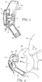
- Figure 3 shows further detail on the operation of the exhaust apparatus 10 and such is a cross-sectional side view of the exhaust apparatus 10 taken along the dashed line A'-A" in Figure 6 .
- the inlet 12 of the exhaust apparatus 10 is shaped to releasably connect by way of an interference fit to the shape and dimensions of the respective exhaust valve 26 situated on the respiratory mask 20.
- the exhaust apparatus 10 described herein in relation to Figure 3 connects by way of an interference fit
- any form of releasable connection to the exhaust valve 26 is possible, including, for example, connection by way of a screw thread, snap fit engagement, bayonet, quick release mechanism etc.
- the above list is in no way intended to be limiting and exhaustive.
- the exhaust apparatus 10 includes a blower which is a motor 30 and fan 32 combination.
- the output of the blower vents through a series of openings which define an outlet 14 on the apparatus 10.
- the blower is contained inside housing 16 positioned between the inlet 12 and the outlet 14, and is configured to draw air through the exhaust apparatus 10 from the inlet 12 to the outlet 14.
- the air flow through the apparatus 10 is shown illustratively via the dashed lines A in Figure 3 .
- the exhaust apparatus 10 includes at least one power source, which is typically at least one battery 34.
- the battery 34 can be any commercially-available battery 34, although the skilled person will appreciate that a compromise is always needed in terms of size and weight of the battery 34, and the capacity and duration of the battery 34.
- a switch mechanism 18 is accessible to the wearer 100.
- the switch mechanism can have a simple on/off mode of operation or can include a variable adjustment so that the wearer 100 can optimize the desired cooling effect based upon the environmental conditions, the task the wearer 100 is undertaking and personal choice.
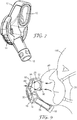
- FIG 4 shows a sectional side view of the exhaust apparatus 10 being operable to draw a portion of the wearer's 100 exhaled breath through a exhaust valve 26 on the personal protection respiratory device 20.
- the illustrative air flow through the respiratory mask 20 and exhaust apparatus 10 being denoted by arrows A.
- a noticeable cooling effect is experienced by the wearer 100 when the blower is configured to operate at a volumetric flow rate of between 0 to 50 litres per minute through the exhaust valve 26.
- the blower may be configured to operate at a volumetric flow rate of over 180 litres per minute through the exhaust valve 26.
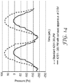
- the best perceived effect in terms of battery life and cooling effect, occurs when the blower matches, or slightly exceeds, the peak exhalation flow rate of the wearer, as shown in Figure 14 .
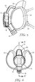
- FIGS 5 to 7 Further illustrations of the exhaust apparatus 10 are shown in Figures 5 to 7 . These show just how a purpose-designed apparatus 20 can be produced which is small, lightweight and balanced on the mask 20. Different designs of apparatus 10 are envisaged and different purpose-designed exhaust apparatuses 10 could also be styled to complement their respective negative pressure respirators 20, which all work in accordance with the mode of operation described herein.
- Figure 8 shows a front side perspective view of an exhaust apparatus 10 according to the present example, and further showing a remotely positionable battery pack 46.
- the apparatus 10 can be configured with a breast pocket-mounted battery pack 46 that incorporates controls, such as an on/off switch 52 and speed adjuster 54, and display 56.
- controls such as an on/off switch 52 and speed adjuster 54
- display 56 By being breast pocket-mounted, and which attach to a wearer's clothing via clip 48, the controls are located in an easy to operate position and the visual display 56 showing battery life is located within the field of view of the wearer 100.
- the breast pocket-mounted battery pack 46 is connected to the blower in exhaust apparatus 10 via a wired connection 50.
- a separate battery pack 46 to reduce the weight and or the size of the exhaust apparatus 10.
- larger capacity batteries can be used, leading to a longer operational time.
- a full range of display 56 options can then be located in the battery pack 46. These can include basic-colored LEDs, LED bargraphs or alphanumeric displays. More complex Graphical User Interface options, including visual and aural alarms/status indicators for flow range, mask pressure, battery, and remaining run time could also be used.
- FIG 8 shows that the remote battery pack 46 is breast-mounted this is in no was intended to be limited as any number of remotely positionable battery configurations are envisaged, such as, for example, belt or waist mounted, helmet or headband mounted, arm or clip mounted.
- Figure 9 shows a sectional side view of the exhaust apparatus 10 according to the present invention, further including a secondary exhalation valve 58 which reduces the exhalation pressure drop when the exhaust apparatus 10 is not powered or if exhaled air flow rate exceeds the amount of air flowing through the exhaust apparatus 10.
- a secondary exhalation valve 58 which reduces the exhalation pressure drop when the exhaust apparatus 10 is not powered or if exhaled air flow rate exceeds the amount of air flowing through the exhaust apparatus 10.
- Respirators 20 such as those fitted with combined particulate and gas and vapor filters, can particularly exhibit a notable increase in the exhalation pressure drop when the exhaust apparatus 10 is not in operation. This is because the exhaled air has to pass through both the respirator exhalation valve 26 and the apparatus 10 and because the respirator 20 is fitted with inhalation valves to prevent exhaled air flowing back though the carbon filters 22, 24.
- the addition of a secondary exhalation valve 58, through exhaust vents 60, in the exhaust apparatus 10 serves to reduce the exhalation pressure drop when the apparatus 10 is not powered. By including a secondary exhalation valve 58 to the apparatus 10, positioned between the inlet 12 of the blower and the motor fan assembly 30, 32 this pressure drop can be reduced.
- the secondary exhalation valve 58 comprises a valve seat that includes a seal surface and a flexible flap, although other configurations are, of course, possible.
- Figure 9 shows the exhalation flow path for an exhaust apparatus fitted with an extra exhalation valve 58.
- This secondary exhalation valve 58 significantly reduces the exhalation pressure drop, as described below in relation to Figure 15 .
- the change in exhalation pressure drop has been determined by conducting constant flow tests through a standard 3MTM 4251 Valved Filtering Half Face Respirator, a 3MTM 4251 Valved Filtering Half Face Respirator fitted with an exhaust apparatus 10, and a 3MTM 4251 Valved Filtering Half Face Respirator fitted with an exhaust apparatus 10 including an additional exhalation valve 58.
- the exhalation pressure drop for all three configurations was measured by conducting constant flow tests with the respirators fitted to a Sheffield test headform. All the measurements taken in Figure 15 were obtained with the blower of the exhaust apparatus 10 not powered.
- the exhalation pressure drop is significantly improved for an apparatus 10 that includes a secondary exhalation valve 58, as the exhaled air passes though the secondary exhalation valve 58 and not through the blower and outlet 14 of the exhaust apparatus 10, as shown schematically in Figure 9 .
- Figure 16 illustrates the measured exhalation pressure drop using a 3MTM 4251 Valved Filtering Half Face Respirator having an exhaust apparatus 10 connected thereto as a function of flow rate and applied voltage.
- the solid line in Figure 16 is the measured exhalation pressure drop for a standard 3MTM 4251 Valved Filtering Half Face Respirator measured against flow rate.
- Figure 16 shows that there is a significant drop in exhalation pressure drop as the voltage to the blower is increased. This is to be expected since the exhaust apparatus 10 draws air out through the blower and reduces exhalation resistance. In use, for the wearer 100 this means it is easier to exhale and it is the continual assisted removal of the hot and moist air inside the respirator 20 through the blower that produces a noticeable cooling effect.
- FIGs 10 and 11 illustrate how an exhaust apparatus 10 according to the present invention can be utilized with a full facepiece respiratory device 70.
- the respirator 70 that is illustrated in Figures 10 and 11 is indicative of the 3MTM 6800 Full Facepiece Reusable Respirator manufactured by 3M Company located in St. Paul, Minnesota.
- filter cartridges 74 are attached at either side of the respirator mask 70 at respective inhalation ports 72.
- Each of the inhalation ports 72 has a respective inhalation valve (not shown) located on the inside of the respirator mask 70 which open as a wearer 100 draws a breath.
- the face mask 70 includes an exhaust valve 80 with a one-way exhalation valve diaphragm 36, and adjustable straps (not shown) for attachment to the wearer 100.
- the respiratory mask 70 has a conformable gasket or seal which generally encloses the wearer's 100 face. Since a good seal is needed to ensure filtration of the containments one major drawback is that sometimes an uncomfortable build-up of heat and moisture is noticed by the wearer 100 inside the respirator 70. As the wearer 100 works harder, and or wears the respirator 70 for extended periods of time, heat and moisture build-up can occur. The heat and moisture build-up is caused by the trapping of the exhaled breath in the cavity created between the respirator 20 and the wearer's 100 face. In a full facepiece respirator 70 the build-up of trapped hot and moist air can also cause the additional problem of visor misting.
- the exhaust apparatus 10 of the present invention is operable to draw a portion of the wearer's 100 exhaled breath through the one-way exhalation valve diaphragm 36 on the personal protection respiratory device 70 to significantly improve and enhance wearer comfort.
- Figures 10 and 11 also show how a standard full facepiece respiratory device 70 can be modified to more effectively control or direct the air flow inside the respirator 70 to give even better improvements in terms of visor misting and the cooling effect experienced by the wearer 100.
- the respiratory device 70 shown in Figures 10 and 11 also includes an additional air distribution manifold 76 that is connected to each of the inhalation ports 72. Located generally above the wearer's 100 eye line is the manifold outlet 78. The air flow through the respiratory device 70 and exhaust apparatus 10 is shown illustratively via the bold lines A in Figures 10 and 11 . As can be seen, as the wearer 100 draws a breath, negative pressure is created in the respirator 70 and air is drawn in through the filter system, comprising the inhalation ports 72, filter cartridges 74, air distribution manifold 76, and the air exits at inside the mask 70 at the manifold outlet 78. The air is then drawn downwards towards the nose and mouth of the wearer 100.
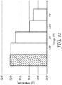
- FIG. 12 shows the average temperature measured inside a 3MTM 4251 Valved Filtering Half Face Respirator as a function of the voltage being applied to the exhaust apparatus 10.
- the results shown in Figure 12 were again obtained using standard respiratory protection test equipment and the respirator 20 was fitted to a Sheffield test head and breathing machine capable of providing a number of pre-set swept volumes of air at variable rates up to 50 strokes per minute.
- the output of the breathing machine was connected to an enclosed box containing a volume of water and a heater element such that the air is warmed and moistened before connection to the Sheffield test headform, which carried the respirator 20 under test.
- thermocouple was placed inside the respirator, in the air volume adjacent to the wearer's 100 nose and mouth and Figure 12 shows the average temperature inside 3MTM 4251 Valved Filtering Half Face Respirator. The temperate readings were each averaged over 5 minute intervals and shows a continuous test run.
- the average temperature inside the standard respirator is around 32.1°C as the test commences. This is illustrated by the shaded block at the left hand side of Figure 12 . As described above, this is because the exhaled air has to pass through both the respirator exhalation valve 26 and the apparatus 10.
- the 3MTM 4251 Valved Filtering Half Face Respirator which is fitted with combined particulate and gas and vapor filters, can particularly exhibit a notable increase in the exhalation pressure drop when the apparatus 10 is not in operation. It is only when the supplied voltage to the exhaust apparatus is increased that a corresponding decrease in the temperature inside the mask is observed. To conclude the test, the exhaust apparatus was then removed and a measurement of the standard 3MTM 4251 Valved Filtering Half Face Respirator was taken to confirm that the temperature of the supplied air had remained constant during the test.
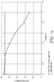
- an exhaust apparatus 10 As well as reducing the temperature inside the respirator 20, the use of an exhaust apparatus 10 according to the present invention also gives a significant reduction in the rebreathed carbon dioxide levels observed inside the respirator, as shown in Figure 13 .
- These measurements were again obtained using standard respiratory protection test equipment with the 3MTM 4251 Valved Filtering Half Face Respirator being fitted to a Sheffield test head using a breathing machine, and an apparatus to provide warm moist exhaled air. These tests being in accordance with EN 405:2001, paragraphs 7.14 and 8.8.
- Figure 13 shows that as well as observing a significant reduction in the temperature observed inside the respirator 20, the measured carbon dioxide levels in front of the wearer's 100 mouth and nose are reduced as the voltage to the exhaust apparatus 10 increases.
- the apparatus 10 draws out the last portion of the wearer's previously exhaled breath so that the first portion of the next breath of the wearer 100 is fresh un-breathed air.
- this reduction in rebreathed carbon dioxide levels observed by using the exhaust apparatus 10 will also enhance wearer comfort.
- Figure 14 is a graph of the measured pressure inside a standard 3MTM 4251 Valved Filtering Half Face Respirator using a breathing machine set at 30 litres per minute, compared to a 3MTM 4251 Valved Filtering Half Face Respirator having an exhaust apparatus 10 connected thereto. Again these measurements were taken using standard respiratory protection test equipment with the 3MTM 4251 Valved Filtering Half Face Respirator being fitted to a Sheffield test head and breathing machine.
- Figure 14 shows the measured pressure inside the respirator 20 as the pneumatic cylinder of the breathing machine provides a pre-set swept volume of air in and out of the respirator 20 and is a simulation of a breathing cycle.
- 3MTM 4251 Valved Filtering Half Face Respirator when the pressure is above 0 Pa this is indicative of the exhale phase of breathing, when hot and moist air is being introduced by the wearer into the mask 20.
- Figure 17 illustrates that the use of an exhaust apparatus 10 according to the present invention gives a significant reduction in the rebreathed carbon dioxide levels observed inside a full facepiece respiratory device 70. These measurements were obtained using standard respiratory protection test equipment with a 3MTM 6800 Full Facepiece Reusable Respirator being fitted to a Sheffield test head using a breathing machine. These tests being in accordance with EN 136:1998, paragraphs 7.18 and 8.14.
- Figure 17 shows that as well as observing a significant reduction in the temperature observed inside the respirator 20, the measured carbon dioxide levels in front of the wearer's 100 mouth and nose are reduced as the voltage to the exhaust apparatus 10 increases.
- Figure 17 also shows that if the inner face cup is removed from the respirator 70 leaving a totally open space encompassing the wearer's 100 face sealed only by the outer conformable gasket or seal then improvements in terms of rebreathed carbon dioxide levels are also observed as the voltage applied to the exhaust apparatus 10 are increased.
Landscapes
- Health & Medical Sciences (AREA)
- General Health & Medical Sciences (AREA)
- Pulmonology (AREA)
- Business, Economics & Management (AREA)
- Emergency Management (AREA)
- Life Sciences & Earth Sciences (AREA)
- Engineering & Computer Science (AREA)
- Emergency Medicine (AREA)
- Anesthesiology (AREA)
- Biomedical Technology (AREA)
- Heart & Thoracic Surgery (AREA)
- Hematology (AREA)
- Animal Behavior & Ethology (AREA)
- Public Health (AREA)
- Veterinary Medicine (AREA)
- Zoology (AREA)
- Respiratory Apparatuses And Protective Means (AREA)
Claims (8)
- Ensemble de protection respiratoire personnelle comprenant un dispositif de protection respiratoire personnelle (100) qui définit un volume d'air filtré adjacent au visage d'un porteur et au moins une soupape d'expiration (26), l'ensemble comprenant en outre un appareil d'échappement (10) qui, pendant l'utilisation, est relié de manière amovible au dispositif de protection respiratoire personnelle,
l'appareil d'échappement comprenant :un boîtier (16) qui définit une entrée (12) qui, pendant l'utilisation, est reliée de manière amovible à la au moins une soupape d'expiration (26), et le boîtier comprend en outre une sortie (14),le boîtier (16) contenant un ensemble moto-ventilateur qui est en communication fluidique avec l'entrée (12) et, pendant l'utilisation, en communication fluidique avec l'au moins une soupape d'expiration (26),dans lequel l'ensemble moto-ventilateur fonctionne, pendant l'utilisation, pour aspirer une partie de l'haleine exhalée du porteur du volume d'air filtré, à travers l'au moins une soupape d'expiration (26) et l'entrée (12),dans lequel l'appareil d'échappement comprend une soupape d'expiration secondaire (58) positionnée entre l'entrée et l'ensemble moto-ventilateur. - Ensemble avec dispositif de protection respiratoire personnelle comme revendiqué dans la revendication 1, comprenant en outre un moyen de fixation pour attacher de façon amovible l'ensemble moto-ventilateur à l'au moins une soupape d'expiration (26).
- Ensemble avec dispositif de protection respiratoire personnelle comme revendiqué dans la revendication 2, dans lequel le moyen de fixation est sélectionné dans un groupe constitué d'un ajustement serré, d'un filetage, d'un engagement par encliquetage, d'une fixation à baïonnette, d'un mécanisme à libération rapide, d'un engagement à glissière et à rainure, d'une goupille de verrouillage, d'une pince de verrouillage et d'un élément de fixation mécanique à crochet et à boucle.
- Ensemble avec dispositif de protection respiratoire personnelle comme revendiqué dans la revendication 1, dans lequel le dispositif de protection respiratoire personnelle est choisi dans un groupe comprenant des respirateurs jetables, réutilisables, à demi-masque, à masque intégral, à gaz, à vapeurs et à capuche bien ajustée.
- Ensemble avec dispositif de protection respiratoire personnelle comme revendiqué dans la revendication 1, dans lequel la soufflante peut fonctionner à un débit volumétrique compris entre 0 et 180 litres par minute.
- Ensemble avec dispositif de protection respiratoire personnelle comme revendiqué dans la revendication 1, dans lequel l'ensemble moto-ventilateur est en communication fluidique avec au moins une soupape d'expiration via un tuyau, tube, conduit ou canal respiratoire.
- Ensemble de dispositif de protection respiratoire personnelle comme revendiqué dans l'une quelconque des revendications précédentes, dans lequel la soupape d'expiration secondaire est formée d'un seul tenant avec l'appareil d'échappement.
- Ensemble de dispositif de protection respiratoire personnelle comme revendiqué dans l'une quelconque des revendications précédentes, dans lequel la soupape d'expiration secondaire comprend un siège de soupape qui comprend une surface d'étanchéité et un volet flexible.
Priority Applications (2)
| Application Number | Priority Date | Filing Date | Title |
|---|---|---|---|
| PL13752764T PL2890463T3 (pl) | 2012-08-31 | 2013-08-12 | Elektryczne urządzenie do wymuszonego odprowadzania powietrza z indywidualnego respiratora ochronnego |
| EP19155503.6A EP3498339A1 (fr) | 2012-08-31 | 2013-08-12 | Appareil d'échappement électrique pour un dispositif respiratoire de protection personnelle |
Applications Claiming Priority (2)
| Application Number | Priority Date | Filing Date | Title |
|---|---|---|---|
| GB1215568.5A GB2505484A (en) | 2012-08-31 | 2012-08-31 | Powered exhaust apparatus for a personal protection respiratory device |
| PCT/US2013/054451 WO2014035641A2 (fr) | 2012-08-31 | 2013-08-12 | Appareil d'échappement électrique pour un dispositif respiratoire de protection personnelle |
Related Child Applications (2)
| Application Number | Title | Priority Date | Filing Date |
|---|---|---|---|
| EP19155503.6A Division EP3498339A1 (fr) | 2012-08-31 | 2013-08-12 | Appareil d'échappement électrique pour un dispositif respiratoire de protection personnelle |
| EP19155503.6A Division-Into EP3498339A1 (fr) | 2012-08-31 | 2013-08-12 | Appareil d'échappement électrique pour un dispositif respiratoire de protection personnelle |
Publications (2)
| Publication Number | Publication Date |
|---|---|
| EP2890463A2 EP2890463A2 (fr) | 2015-07-08 |
| EP2890463B1 true EP2890463B1 (fr) | 2019-07-24 |
Family
ID=47075083
Family Applications (2)
| Application Number | Title | Priority Date | Filing Date |
|---|---|---|---|
| EP13752764.4A Active EP2890463B1 (fr) | 2012-08-31 | 2013-08-12 | Appareil d'échappement électrique pour un dispositif respiratoire de protection personnelle |
| EP19155503.6A Pending EP3498339A1 (fr) | 2012-08-31 | 2013-08-12 | Appareil d'échappement électrique pour un dispositif respiratoire de protection personnelle |
Family Applications After (1)
| Application Number | Title | Priority Date | Filing Date |
|---|---|---|---|
| EP19155503.6A Pending EP3498339A1 (fr) | 2012-08-31 | 2013-08-12 | Appareil d'échappement électrique pour un dispositif respiratoire de protection personnelle |
Country Status (12)
| Country | Link |
|---|---|
| US (2) | US20150202473A1 (fr) |
| EP (2) | EP2890463B1 (fr) |
| JP (2) | JP2015530148A (fr) |
| KR (3) | KR102430089B1 (fr) |
| CN (2) | CN108465172B (fr) |
| AU (2) | AU2013309313A1 (fr) |
| BR (1) | BR112015004105A2 (fr) |
| CA (1) | CA2882959A1 (fr) |
| GB (1) | GB2505484A (fr) |
| PL (1) | PL2890463T3 (fr) |
| RU (1) | RU2622824C2 (fr) |
| WO (1) | WO2014035641A2 (fr) |
Cited By (2)
| Publication number | Priority date | Publication date | Assignee | Title |
|---|---|---|---|---|
| US11779724B2 (en) | 2019-06-11 | 2023-10-10 | Sunmed Group Holdings, Llc | Respiration sensor attachment device |
| US11857710B2 (en) | 2018-07-31 | 2024-01-02 | Sunmed Group Holdings, Llc | Ventilation mask |
Families Citing this family (52)
| Publication number | Priority date | Publication date | Assignee | Title |
|---|---|---|---|---|
| GB2508184A (en) * | 2012-11-22 | 2014-05-28 | 3M Innovative Properties Co | Powered exhaust apparatus for respiratory device |
| USD778430S1 (en) * | 2013-11-15 | 2017-02-07 | 3M Innovative Properties Company | Filter cartridge |
| GB2515847B (en) * | 2013-12-04 | 2015-05-27 | Design Reality Ltd | Respirators |
| WO2015084255A1 (fr) * | 2013-12-04 | 2015-06-11 | Singapore Technologies Dynamics Pte Ltd | Système de ventilation active et dispositifs contenant un système de ventilation active |
| SG2013097191A (en) * | 2013-12-04 | 2015-07-30 | Innosparks Pte Ltd | Respiratory device with active venting system |
| AU358653S (en) * | 2014-05-08 | 2014-11-11 | Innosparks Pte Ltd | Disposable respirator with child active venting system |
| JP2017516546A (ja) * | 2014-05-26 | 2017-06-22 | イノスパークス ピーティーイー リミテッドInnosparks Pte Ltd | 能動型通気システムを装着するための一方向弁を有する呼吸装置 |
| USD757248S1 (en) * | 2014-05-29 | 2016-05-24 | Jsp Ltd | Respiratory mask filter |
| USD764656S1 (en) * | 2014-06-26 | 2016-08-23 | Moldex-Metric, Inc. | Compact mask with changeable filters |
| AU362443S (en) * | 2015-01-14 | 2015-07-07 | Jsp Ltd | Respiratory mask component |
| GB201511904D0 (en) * | 2015-07-07 | 2015-08-19 | 3M Innovative Properties Co | Powered exhaust apparatus for a personal protection respiratory device |
| US10342999B2 (en) | 2015-10-16 | 2019-07-09 | Yang Song | Particulate filter face mask having fan breathing assist |
| EP3407950B1 (fr) * | 2016-01-28 | 2021-08-11 | Invent Medical Corporation | Système pour prévenir une contamination croisée dans des systèmes de génération d'écoulement |
| US11219787B2 (en) * | 2016-03-28 | 2022-01-11 | 3M Innovative Properties Company | Respirator fit check sealing devices and methods |
| CN105771108A (zh) * | 2016-05-04 | 2016-07-20 | 上海美晟环境技术股份公司 | 一种便携式空气净化设备 |
| GB201609168D0 (en) | 2016-05-25 | 2016-07-06 | 3M Innovative Properties Co | Exhaust valve shroud for a personal protection respiratory device |
| WO2018016852A1 (fr) * | 2016-07-18 | 2018-01-25 | 신홍제 | Masque fonctionnel |
| CN106139349A (zh) * | 2016-08-03 | 2016-11-23 | 深圳市安保科技有限公司 | 一种呼吸设备的通气方法及装置 |
| CN106362319A (zh) * | 2016-09-28 | 2017-02-01 | 武汉大学 | 一种智能风扇口罩 |
| CN107232664A (zh) * | 2017-07-06 | 2017-10-10 | 东莞市安域实业有限公司 | 一种防霾口罩 |
| CN107823770A (zh) * | 2017-10-27 | 2018-03-23 | 苏玉强 | 一种麻醉面罩 |
| CN108498970B (zh) * | 2018-04-08 | 2020-06-30 | 浙江带立新材料科技有限公司 | 卡接固定出气单向阀的消防自救呼吸器 |
| CN108514697B (zh) * | 2018-04-08 | 2020-06-30 | 浙江带立新材料科技有限公司 | 一体连接夹持固定式消防自救呼吸器 |
| RU186166U1 (ru) * | 2018-04-17 | 2019-01-11 | Акционерное общество "Научно-Производственное Предприятие "РЕСПИРАТОР" | Устройство подогрева дыхательной смеси |
| GB2575050B (en) * | 2018-06-26 | 2022-09-14 | Draeger Safety Uk Ltd | Connection apparatus for breathing apparatus |
| CN109572963A (zh) * | 2019-01-17 | 2019-04-05 | 东莞市蓝豚运动用品有限公司 | 潜水面罩 |
| EP3921041A4 (fr) * | 2019-02-06 | 2023-06-28 | Cleanspace IP Pty Ltd. | Respirateur à ajustement serré avec filtre d'expiration et filtre d'expiration pour respirateur à ajustement serré |
| US10835704B1 (en) * | 2019-05-15 | 2020-11-17 | Applied Research Associates, Inc. | Reusable respiratory protection device |
| EP3797837A1 (fr) * | 2019-09-30 | 2021-03-31 | 3M Innovative Properties Company | Appareil d'échappement électrique pour dispositif de protection personnelle respiratoire |
| CN111350533A (zh) * | 2020-03-20 | 2020-06-30 | 佛山市金净创环保技术有限公司 | 一种应对富尘工作环境的劳保防护装置及防护方法 |
| WO2021195115A1 (fr) * | 2020-03-24 | 2021-09-30 | Justair, Inc. | Procédé et appareil d'isolation et/ou de protection personnelle |
| EP4126256A1 (fr) * | 2020-03-27 | 2023-02-08 | Automacube S.r.l. | Dispositif de protection et d'isolation individuelles contre des polluants et des microorganismes et groupe de filtration pour dispositifs de protection et d'isolation |
| US11471711B2 (en) * | 2020-04-30 | 2022-10-18 | Medibotics Llc | Smart mask with a transparent mouth-covering portion and impellor- driven air filtration |
| CN115605244A (zh) * | 2020-05-20 | 2023-01-13 | 深圳迈瑞生物医疗电子股份有限公司(Cn) | 医用通气设备、控制方法及存储介质 |
| WO2021247411A1 (fr) * | 2020-06-01 | 2021-12-09 | 3Palmeri Martin | Système et procédé de purification de l'air |
| KR102452392B1 (ko) * | 2020-06-05 | 2022-10-11 | 엘지전자 주식회사 | 마스크 장치 |
| KR102384270B1 (ko) | 2020-06-05 | 2022-04-07 | 엘지전자 주식회사 | 마스크 장치 |
| KR102367071B1 (ko) * | 2020-06-05 | 2022-02-25 | 엘지전자 주식회사 | 마스크 장치 |
| KR102494579B1 (ko) * | 2020-06-05 | 2023-02-02 | 엘지전자 주식회사 | 마스크 장치 |
| RU2757884C1 (ru) * | 2020-06-15 | 2021-10-22 | Александр Александрович Котровский | Универсальный защитный шлем |
| KR102460798B1 (ko) | 2020-06-30 | 2022-10-31 | 엘지전자 주식회사 | 마스크 장치 |
| KR102418745B1 (ko) | 2020-06-30 | 2022-07-11 | 엘지전자 주식회사 | 마스크 장치 |
| US20220008759A1 (en) * | 2020-07-12 | 2022-01-13 | Zverse, Inc. | Active respiratory open face shield system |
| US20220072245A1 (en) * | 2020-09-09 | 2022-03-10 | SafER Medical Products, LLC | Vacuum shield assembly for attachment to medical masks |
| WO2022087140A1 (fr) * | 2020-10-21 | 2022-04-28 | DRS Innovations LLC | Protection pour le visage à filtration d'air alimentée |
| EP4237751A1 (fr) * | 2020-11-01 | 2023-09-06 | RHT Limited | Respirateur et système de purification d'air |
| USD935600S1 (en) * | 2021-03-03 | 2021-11-09 | Cliff R. Rusin | Mask filter |
| CN113509586B (zh) * | 2021-08-04 | 2022-10-11 | 河南科技大学第一附属医院 | 一种用于感染科肺结核患者的呼吸保护装置 |
| TWI773518B (zh) * | 2021-09-07 | 2022-08-01 | 闕宗熙 | 一種即時產出滅活病毒氣霧及呼吸道病毒疫苗投放之裝置及方法 |
| CN114733096B (zh) * | 2022-05-17 | 2022-11-15 | 杭州中安安全技术咨询有限公司 | 过滤式面罩呼吸器分配器 |
| GB2622051A (en) * | 2022-08-31 | 2024-03-06 | Dyson Technology Ltd | Wearable air purifier |
| GB2622052A (en) * | 2022-08-31 | 2024-03-06 | Dyson Technology Ltd | Wearable air purifier |
Citations (6)
| Publication number | Priority date | Publication date | Assignee | Title |
|---|---|---|---|---|
| US2891541A (en) * | 1959-06-23 | Anti-fogging face mask | ||
| US5036842A (en) * | 1988-12-23 | 1991-08-06 | Dragerwerk Aktiengesellschaft | Respirator with blower support and regeneration of the breathing filter |
| CN1076633A (zh) * | 1992-11-19 | 1993-09-29 | 房坤 | 风机通风式防尘口罩 |
| CN1189384A (zh) * | 1997-01-26 | 1998-08-05 | 刘�英 | 电子口罩 |
| US6257235B1 (en) * | 1999-05-28 | 2001-07-10 | Kimberly-Clark Worldwide, Inc. | Face mask with fan attachment |
| CN201578772U (zh) * | 2010-01-26 | 2010-09-15 | 宋儒钧 | 安全呼吸器 |
Family Cites Families (36)
| Publication number | Priority date | Publication date | Assignee | Title |
|---|---|---|---|---|
| FR854223A (fr) * | 1938-12-24 | 1940-04-08 | Dispositif facilitant la respiration des porteurs de masques à gaz du type filtrant | |
| US3130722A (en) * | 1959-09-08 | 1964-04-28 | Protective Treat S Inc | Respiratory mask |
| US3859995A (en) * | 1973-07-02 | 1975-01-14 | Westinghouse Electric Corp | Breathing assist apparatus |
| US4265239A (en) * | 1978-11-27 | 1981-05-05 | Fischer Jr Charles M | Gas scavenging exhaust system |
| US4549542A (en) * | 1983-07-25 | 1985-10-29 | Chien Chao Huei | Multiple-effect respirator |
| US4646732A (en) * | 1985-08-26 | 1987-03-03 | Chien Chao Huei | Circulative respiratory mask |
| GB8826864D0 (en) * | 1988-11-17 | 1988-12-21 | Cybertronics Ltd | Improvements in & relating to protective hoods |
| GB2234440B (en) * | 1989-07-19 | 1993-04-14 | Sabre Safety Ltd | Respiratory protective apparatus |
| US5009225A (en) | 1989-11-30 | 1991-04-23 | Boehringer Mannheim Corporation | Personal ventilating system |
| US5592935A (en) * | 1995-05-03 | 1997-01-14 | Minnesota Mining And Manufacturing Company | Positive/negative air pressure adaptor for use with respirators |
| RU2114654C1 (ru) * | 1997-07-31 | 1998-07-10 | Акционерное общество закрытого типа "Сорбент-Центр Внедрение" | Шланговый противогаз |
| AUPQ446299A0 (en) * | 1999-12-02 | 2000-01-06 | Collins, Ralph | Micromachines |
| JP4264619B2 (ja) | 2001-10-12 | 2009-05-20 | 山本光学株式会社 | 呼吸用保護具 |
| RU2203704C1 (ru) * | 2002-04-03 | 2003-05-10 | Шестаченко Флориан Александрович | Дыхательный аппарат индивидуального пользования |
| JP3780455B2 (ja) * | 2002-06-25 | 2006-05-31 | 興研株式会社 | ブロワー付マスク装置 |
| GB0222497D0 (en) * | 2002-09-27 | 2002-11-06 | Secr Defence | Respirator |
| GB2404866B (en) * | 2003-08-15 | 2008-02-27 | Shahar Hayek | Respiratory apparatus |
| TWI282288B (en) | 2003-08-20 | 2007-06-11 | Jun-Shin Chang | Medical mask with supply of hot air for treating respiratory tract diseases like SARS |
| JP2006102324A (ja) * | 2004-10-07 | 2006-04-20 | Shigematsu Works Co Ltd | 電動ファン付呼吸用保護具 |
| CN2794549Y (zh) | 2005-05-10 | 2006-07-12 | 赵闻山 | 电动口罩 |
| US20070163587A1 (en) * | 2006-01-19 | 2007-07-19 | Teibel Jeffrey L | Oral respirator device and method for mask-free filtering of particulates from breathed air |
| US7762252B2 (en) | 2006-04-26 | 2010-07-27 | Mine Safety Appliances Company | Devices, systems and methods for operation of breathing apparatuses in multiple modes |
| JP4612606B2 (ja) | 2006-10-04 | 2011-01-12 | 興研株式会社 | ブロワー付マスク装置 |
| JP4931626B2 (ja) | 2007-02-08 | 2012-05-16 | 興研株式会社 | 呼吸連動型ブロワーマスクシステム |
| JP2008289600A (ja) | 2007-05-23 | 2008-12-04 | Koken Ltd | 呼吸連動型ブロワーマスク装置 |
| JP2008295993A (ja) * | 2007-05-31 | 2008-12-11 | Toyo Living Kk | 光触媒付加のサイクロン式マスク |
| PL2205324T3 (pl) | 2007-10-05 | 2018-11-30 | 3M Innovative Properties Company | Aparatura i sposób regulacji przepływu powietrza w respiratorze |
| JP2011502704A (ja) | 2007-11-12 | 2011-01-27 | スリーエム イノベイティブ プロパティズ カンパニー | 空気流の方向制御を備えた呼吸装置組立品 |
| JP5041596B2 (ja) * | 2007-12-07 | 2012-10-03 | 株式会社重松製作所 | 呼吸装置 |
| WO2009123809A2 (fr) | 2008-04-04 | 2009-10-08 | 3M Innovative Properties Company | Système de respirateur comprenant un élément de recouvrement de tête convertible |
| CN201257125Y (zh) | 2008-09-23 | 2009-06-17 | 浙江理工大学 | 人工呼吸器 |
| KR20100003793U (ko) * | 2008-10-01 | 2010-04-09 | 박세현 | 공기 순환식 방독면 |
| WO2011043262A1 (fr) * | 2009-10-07 | 2011-04-14 | 株式会社重松製作所 | Dispositif respiratoire |
| JP5578700B2 (ja) * | 2009-10-07 | 2014-08-27 | 株式会社重松製作所 | 呼吸装置 |
| CN202236942U (zh) | 2011-10-13 | 2012-05-30 | 吴琼 | 一种矿用可循环换风防尘装置 |
| CN202445175U (zh) | 2012-01-10 | 2012-09-26 | 罗建平 | 新风防尘口罩 |
-
2012
- 2012-08-31 GB GB1215568.5A patent/GB2505484A/en not_active Withdrawn
-
2013
- 2013-08-12 US US14/423,155 patent/US20150202473A1/en not_active Abandoned
- 2013-08-12 EP EP13752764.4A patent/EP2890463B1/fr active Active
- 2013-08-12 EP EP19155503.6A patent/EP3498339A1/fr active Pending
- 2013-08-12 BR BR112015004105A patent/BR112015004105A2/pt active Search and Examination
- 2013-08-12 CA CA2882959A patent/CA2882959A1/fr active Pending
- 2013-08-12 CN CN201810153847.1A patent/CN108465172B/zh active Active
- 2013-08-12 RU RU2015108157A patent/RU2622824C2/ru not_active IP Right Cessation
- 2013-08-12 KR KR1020227001614A patent/KR102430089B1/ko active IP Right Grant
- 2013-08-12 AU AU2013309313A patent/AU2013309313A1/en not_active Abandoned
- 2013-08-12 WO PCT/US2013/054451 patent/WO2014035641A2/fr active Application Filing
- 2013-08-12 KR KR1020207022612A patent/KR102433839B1/ko active IP Right Grant
- 2013-08-12 CN CN201380044575.7A patent/CN104780979A/zh active Pending
- 2013-08-12 KR KR1020157007909A patent/KR102143740B1/ko active IP Right Grant
- 2013-08-12 PL PL13752764T patent/PL2890463T3/pl unknown
- 2013-08-12 JP JP2015529832A patent/JP2015530148A/ja active Pending
-
2016
- 2016-08-26 AU AU2016219689A patent/AU2016219689B2/en not_active Ceased
-
2018
- 2018-06-06 JP JP2018108291A patent/JP6612390B2/ja active Active
-
2022
- 2022-08-02 US US17/816,746 patent/US20220370837A1/en active Pending
Patent Citations (6)
| Publication number | Priority date | Publication date | Assignee | Title |
|---|---|---|---|---|
| US2891541A (en) * | 1959-06-23 | Anti-fogging face mask | ||
| US5036842A (en) * | 1988-12-23 | 1991-08-06 | Dragerwerk Aktiengesellschaft | Respirator with blower support and regeneration of the breathing filter |
| CN1076633A (zh) * | 1992-11-19 | 1993-09-29 | 房坤 | 风机通风式防尘口罩 |
| CN1189384A (zh) * | 1997-01-26 | 1998-08-05 | 刘�英 | 电子口罩 |
| US6257235B1 (en) * | 1999-05-28 | 2001-07-10 | Kimberly-Clark Worldwide, Inc. | Face mask with fan attachment |
| CN201578772U (zh) * | 2010-01-26 | 2010-09-15 | 宋儒钧 | 安全呼吸器 |
Cited By (2)
| Publication number | Priority date | Publication date | Assignee | Title |
|---|---|---|---|---|
| US11857710B2 (en) | 2018-07-31 | 2024-01-02 | Sunmed Group Holdings, Llc | Ventilation mask |
| US11779724B2 (en) | 2019-06-11 | 2023-10-10 | Sunmed Group Holdings, Llc | Respiration sensor attachment device |
Also Published As
| Publication number | Publication date |
|---|---|
| US20150202473A1 (en) | 2015-07-23 |
| GB2505484A (en) | 2014-03-05 |
| KR102430089B1 (ko) | 2022-08-05 |
| CN108465172A (zh) | 2018-08-31 |
| BR112015004105A2 (pt) | 2017-07-04 |
| PL2890463T3 (pl) | 2020-01-31 |
| KR20150052143A (ko) | 2015-05-13 |
| KR20200096330A (ko) | 2020-08-11 |
| JP2015530148A (ja) | 2015-10-15 |
| AU2016219689B2 (en) | 2018-04-05 |
| RU2015108157A (ru) | 2016-10-27 |
| KR20220024641A (ko) | 2022-03-03 |
| WO2014035641A2 (fr) | 2014-03-06 |
| KR102143740B1 (ko) | 2020-08-12 |
| JP6612390B2 (ja) | 2019-11-27 |
| US20220370837A1 (en) | 2022-11-24 |
| WO2014035641A3 (fr) | 2014-11-20 |
| CN104780979A (zh) | 2015-07-15 |
| EP3498339A1 (fr) | 2019-06-19 |
| AU2013309313A1 (en) | 2015-03-19 |
| CA2882959A1 (fr) | 2014-03-06 |
| AU2016219689A1 (en) | 2016-09-15 |
| JP2018158128A (ja) | 2018-10-11 |
| RU2622824C2 (ru) | 2017-06-20 |
| GB201215568D0 (en) | 2012-10-17 |
| CN108465172B (zh) | 2021-10-22 |
| KR102433839B1 (ko) | 2022-08-18 |
| EP2890463A2 (fr) | 2015-07-08 |
Similar Documents
| Publication | Publication Date | Title |
|---|---|---|
| US20220370837A1 (en) | Powered exhaust apparatus for a personal protection respiratory device | |
| AU2016277663B2 (en) | Powered exhaust apparatus for a personal protection respiratory device | |
| CN107735148B (zh) | 用于个人防护呼吸装置的动力排气设备 | |
| EP2969045B1 (fr) | Respirateur avec matériau à changement de phase | |
| US20200038614A1 (en) | Powered Apparatus for a Personal Protection Respiratory Device | |
| GB2032284A (en) | Improvements in and relating to breathing apparatus | |
| EP3797837A1 (fr) | Appareil d'échappement électrique pour dispositif de protection personnelle respiratoire |
Legal Events
| Date | Code | Title | Description |
|---|---|---|---|
| PUAI | Public reference made under article 153(3) epc to a published international application that has entered the european phase |
Free format text: ORIGINAL CODE: 0009012 |
|
| 17P | Request for examination filed |
Effective date: 20150327 |
|
| AK | Designated contracting states |
Kind code of ref document: A2 Designated state(s): AL AT BE BG CH CY CZ DE DK EE ES FI FR GB GR HR HU IE IS IT LI LT LU LV MC MK MT NL NO PL PT RO RS SE SI SK SM TR |
|
| AX | Request for extension of the european patent |
Extension state: BA ME |
|
| TPAC | Observations filed by third parties |
Free format text: ORIGINAL CODE: EPIDOSNTIPA |
|
| TPAC | Observations filed by third parties |
Free format text: ORIGINAL CODE: EPIDOSNTIPA |
|
| DAX | Request for extension of the european patent (deleted) | ||
| 17Q | First examination report despatched |
Effective date: 20151222 |
|
| STAA | Information on the status of an ep patent application or granted ep patent |
Free format text: STATUS: THE APPLICATION IS DEEMED TO BE WITHDRAWN |
|
| 18D | Application deemed to be withdrawn |
Effective date: 20160702 |
|
| 18RA | Request filed for re-establishment of rights before grant |
Effective date: 20170123 |
|
| 18RA | Request filed for re-establishment of rights before grant |
Effective date: 20170123 |
|
| STAA | Information on the status of an ep patent application or granted ep patent |
Free format text: STATUS: EXAMINATION IS IN PROGRESS |
|
| D18D | Application deemed to be withdrawn (deleted) | ||
| GRAP | Despatch of communication of intention to grant a patent |
Free format text: ORIGINAL CODE: EPIDOSNIGR1 |
|
| STAA | Information on the status of an ep patent application or granted ep patent |
Free format text: STATUS: GRANT OF PATENT IS INTENDED |
|
| INTG | Intention to grant announced |
Effective date: 20180801 |
|
| GRAS | Grant fee paid |
Free format text: ORIGINAL CODE: EPIDOSNIGR3 |
|
| GRAA | (expected) grant |
Free format text: ORIGINAL CODE: 0009210 |
|
| STAA | Information on the status of an ep patent application or granted ep patent |
Free format text: STATUS: THE PATENT HAS BEEN GRANTED |
|
| AK | Designated contracting states |
Kind code of ref document: B1 Designated state(s): AL AT BE BG CH CY CZ DE DK EE ES FI FR GB GR HR HU IE IS IT LI LT LU LV MC MK MT NL NO PL PT RO RS SE SI SK SM TR |
|
| REG | Reference to a national code |
Ref country code: CH Ref legal event code: EP |
|
| REG | Reference to a national code |
Ref country code: DE Ref legal event code: R096 Ref document number: 602013058189 Country of ref document: DE |
|
| REG | Reference to a national code |
Ref country code: AT Ref legal event code: REF Ref document number: 1157507 Country of ref document: AT Kind code of ref document: T Effective date: 20190815 |
|
| REG | Reference to a national code |
Ref country code: IE Ref legal event code: FG4D |
|
| REG | Reference to a national code |
Ref country code: NL Ref legal event code: MP Effective date: 20190724 |
|
| REG | Reference to a national code |
Ref country code: LT Ref legal event code: MG4D |
|
| REG | Reference to a national code |
Ref country code: AT Ref legal event code: MK05 Ref document number: 1157507 Country of ref document: AT Kind code of ref document: T Effective date: 20190724 |
|
| PG25 | Lapsed in a contracting state [announced via postgrant information from national office to epo] |
Ref country code: HR Free format text: LAPSE BECAUSE OF FAILURE TO SUBMIT A TRANSLATION OF THE DESCRIPTION OR TO PAY THE FEE WITHIN THE PRESCRIBED TIME-LIMIT Effective date: 20190724 Ref country code: LT Free format text: LAPSE BECAUSE OF FAILURE TO SUBMIT A TRANSLATION OF THE DESCRIPTION OR TO PAY THE FEE WITHIN THE PRESCRIBED TIME-LIMIT Effective date: 20190724 Ref country code: BG Free format text: LAPSE BECAUSE OF FAILURE TO SUBMIT A TRANSLATION OF THE DESCRIPTION OR TO PAY THE FEE WITHIN THE PRESCRIBED TIME-LIMIT Effective date: 20191024 Ref country code: SE Free format text: LAPSE BECAUSE OF FAILURE TO SUBMIT A TRANSLATION OF THE DESCRIPTION OR TO PAY THE FEE WITHIN THE PRESCRIBED TIME-LIMIT Effective date: 20190724 Ref country code: PT Free format text: LAPSE BECAUSE OF FAILURE TO SUBMIT A TRANSLATION OF THE DESCRIPTION OR TO PAY THE FEE WITHIN THE PRESCRIBED TIME-LIMIT Effective date: 20191125 Ref country code: NL Free format text: LAPSE BECAUSE OF FAILURE TO SUBMIT A TRANSLATION OF THE DESCRIPTION OR TO PAY THE FEE WITHIN THE PRESCRIBED TIME-LIMIT Effective date: 20190724 Ref country code: FI Free format text: LAPSE BECAUSE OF FAILURE TO SUBMIT A TRANSLATION OF THE DESCRIPTION OR TO PAY THE FEE WITHIN THE PRESCRIBED TIME-LIMIT Effective date: 20190724 Ref country code: AT Free format text: LAPSE BECAUSE OF FAILURE TO SUBMIT A TRANSLATION OF THE DESCRIPTION OR TO PAY THE FEE WITHIN THE PRESCRIBED TIME-LIMIT Effective date: 20190724 Ref country code: NO Free format text: LAPSE BECAUSE OF FAILURE TO SUBMIT A TRANSLATION OF THE DESCRIPTION OR TO PAY THE FEE WITHIN THE PRESCRIBED TIME-LIMIT Effective date: 20191024 |
|
| PG25 | Lapsed in a contracting state [announced via postgrant information from national office to epo] |
Ref country code: IS Free format text: LAPSE BECAUSE OF FAILURE TO SUBMIT A TRANSLATION OF THE DESCRIPTION OR TO PAY THE FEE WITHIN THE PRESCRIBED TIME-LIMIT Effective date: 20191124 Ref country code: RS Free format text: LAPSE BECAUSE OF FAILURE TO SUBMIT A TRANSLATION OF THE DESCRIPTION OR TO PAY THE FEE WITHIN THE PRESCRIBED TIME-LIMIT Effective date: 20190724 Ref country code: LV Free format text: LAPSE BECAUSE OF FAILURE TO SUBMIT A TRANSLATION OF THE DESCRIPTION OR TO PAY THE FEE WITHIN THE PRESCRIBED TIME-LIMIT Effective date: 20190724 Ref country code: ES Free format text: LAPSE BECAUSE OF FAILURE TO SUBMIT A TRANSLATION OF THE DESCRIPTION OR TO PAY THE FEE WITHIN THE PRESCRIBED TIME-LIMIT Effective date: 20190724 Ref country code: AL Free format text: LAPSE BECAUSE OF FAILURE TO SUBMIT A TRANSLATION OF THE DESCRIPTION OR TO PAY THE FEE WITHIN THE PRESCRIBED TIME-LIMIT Effective date: 20190724 Ref country code: GR Free format text: LAPSE BECAUSE OF FAILURE TO SUBMIT A TRANSLATION OF THE DESCRIPTION OR TO PAY THE FEE WITHIN THE PRESCRIBED TIME-LIMIT Effective date: 20191025 |
|
| PG25 | Lapsed in a contracting state [announced via postgrant information from national office to epo] |
Ref country code: TR Free format text: LAPSE BECAUSE OF FAILURE TO SUBMIT A TRANSLATION OF THE DESCRIPTION OR TO PAY THE FEE WITHIN THE PRESCRIBED TIME-LIMIT Effective date: 20190724 |
|
| PG25 | Lapsed in a contracting state [announced via postgrant information from national office to epo] |
Ref country code: DK Free format text: LAPSE BECAUSE OF FAILURE TO SUBMIT A TRANSLATION OF THE DESCRIPTION OR TO PAY THE FEE WITHIN THE PRESCRIBED TIME-LIMIT Effective date: 20190724 Ref country code: EE Free format text: LAPSE BECAUSE OF FAILURE TO SUBMIT A TRANSLATION OF THE DESCRIPTION OR TO PAY THE FEE WITHIN THE PRESCRIBED TIME-LIMIT Effective date: 20190724 Ref country code: RO Free format text: LAPSE BECAUSE OF FAILURE TO SUBMIT A TRANSLATION OF THE DESCRIPTION OR TO PAY THE FEE WITHIN THE PRESCRIBED TIME-LIMIT Effective date: 20190724 Ref country code: IT Free format text: LAPSE BECAUSE OF FAILURE TO SUBMIT A TRANSLATION OF THE DESCRIPTION OR TO PAY THE FEE WITHIN THE PRESCRIBED TIME-LIMIT Effective date: 20190724 |
|
| PG25 | Lapsed in a contracting state [announced via postgrant information from national office to epo] |
Ref country code: IS Free format text: LAPSE BECAUSE OF FAILURE TO SUBMIT A TRANSLATION OF THE DESCRIPTION OR TO PAY THE FEE WITHIN THE PRESCRIBED TIME-LIMIT Effective date: 20200224 Ref country code: SM Free format text: LAPSE BECAUSE OF FAILURE TO SUBMIT A TRANSLATION OF THE DESCRIPTION OR TO PAY THE FEE WITHIN THE PRESCRIBED TIME-LIMIT Effective date: 20190724 Ref country code: LI Free format text: LAPSE BECAUSE OF NON-PAYMENT OF DUE FEES Effective date: 20190831 Ref country code: MC Free format text: LAPSE BECAUSE OF FAILURE TO SUBMIT A TRANSLATION OF THE DESCRIPTION OR TO PAY THE FEE WITHIN THE PRESCRIBED TIME-LIMIT Effective date: 20190724 Ref country code: SK Free format text: LAPSE BECAUSE OF FAILURE TO SUBMIT A TRANSLATION OF THE DESCRIPTION OR TO PAY THE FEE WITHIN THE PRESCRIBED TIME-LIMIT Effective date: 20190724 Ref country code: LU Free format text: LAPSE BECAUSE OF NON-PAYMENT OF DUE FEES Effective date: 20190812 Ref country code: CZ Free format text: LAPSE BECAUSE OF FAILURE TO SUBMIT A TRANSLATION OF THE DESCRIPTION OR TO PAY THE FEE WITHIN THE PRESCRIBED TIME-LIMIT Effective date: 20190724 Ref country code: CH Free format text: LAPSE BECAUSE OF NON-PAYMENT OF DUE FEES Effective date: 20190831 |
|
| REG | Reference to a national code |
Ref country code: BE Ref legal event code: MM Effective date: 20190831 |
|
| REG | Reference to a national code |
Ref country code: DE Ref legal event code: R097 Ref document number: 602013058189 Country of ref document: DE |
|
| PLBE | No opposition filed within time limit |
Free format text: ORIGINAL CODE: 0009261 |
|
| STAA | Information on the status of an ep patent application or granted ep patent |
Free format text: STATUS: NO OPPOSITION FILED WITHIN TIME LIMIT |
|
| PG2D | Information on lapse in contracting state deleted |
Ref country code: IS |
|
| PG25 | Lapsed in a contracting state [announced via postgrant information from national office to epo] |
Ref country code: IE Free format text: LAPSE BECAUSE OF NON-PAYMENT OF DUE FEES Effective date: 20190812 |
|
| 26N | No opposition filed |
Effective date: 20200603 |
|
| PG25 | Lapsed in a contracting state [announced via postgrant information from national office to epo] |
Ref country code: SI Free format text: LAPSE BECAUSE OF FAILURE TO SUBMIT A TRANSLATION OF THE DESCRIPTION OR TO PAY THE FEE WITHIN THE PRESCRIBED TIME-LIMIT Effective date: 20190724 Ref country code: BE Free format text: LAPSE BECAUSE OF NON-PAYMENT OF DUE FEES Effective date: 20190831 |
|
| PGFP | Annual fee paid to national office [announced via postgrant information from national office to epo] |
Ref country code: PL Payment date: 20200609 Year of fee payment: 8 |
|
| PG25 | Lapsed in a contracting state [announced via postgrant information from national office to epo] |
Ref country code: CY Free format text: LAPSE BECAUSE OF FAILURE TO SUBMIT A TRANSLATION OF THE DESCRIPTION OR TO PAY THE FEE WITHIN THE PRESCRIBED TIME-LIMIT Effective date: 20190724 |
|
| PG25 | Lapsed in a contracting state [announced via postgrant information from national office to epo] |
Ref country code: HU Free format text: LAPSE BECAUSE OF FAILURE TO SUBMIT A TRANSLATION OF THE DESCRIPTION OR TO PAY THE FEE WITHIN THE PRESCRIBED TIME-LIMIT; INVALID AB INITIO Effective date: 20130812 Ref country code: MT Free format text: LAPSE BECAUSE OF FAILURE TO SUBMIT A TRANSLATION OF THE DESCRIPTION OR TO PAY THE FEE WITHIN THE PRESCRIBED TIME-LIMIT Effective date: 20190724 |
|
| PG25 | Lapsed in a contracting state [announced via postgrant information from national office to epo] |
Ref country code: MK Free format text: LAPSE BECAUSE OF FAILURE TO SUBMIT A TRANSLATION OF THE DESCRIPTION OR TO PAY THE FEE WITHIN THE PRESCRIBED TIME-LIMIT Effective date: 20190724 |
|
| P01 | Opt-out of the competence of the unified patent court (upc) registered |
Effective date: 20230530 |
|
| PGFP | Annual fee paid to national office [announced via postgrant information from national office to epo] |
Ref country code: GB Payment date: 20230720 Year of fee payment: 11 |
|
| PGFP | Annual fee paid to national office [announced via postgrant information from national office to epo] |
Ref country code: FR Payment date: 20230720 Year of fee payment: 11 Ref country code: DE Payment date: 20230720 Year of fee payment: 11 |