EP2889979A1 - Methods and systems for subsea boosting with direct current and alternating current power systems - Google Patents
Methods and systems for subsea boosting with direct current and alternating current power systems Download PDFInfo
- Publication number
- EP2889979A1 EP2889979A1 EP14199483.0A EP14199483A EP2889979A1 EP 2889979 A1 EP2889979 A1 EP 2889979A1 EP 14199483 A EP14199483 A EP 14199483A EP 2889979 A1 EP2889979 A1 EP 2889979A1
- Authority
- EP
- European Patent Office
- Prior art keywords
- power
- subsea boosting
- subsea
- module
- fluid
- Prior art date
- Legal status (The legal status is an assumption and is not a legal conclusion. Google has not performed a legal analysis and makes no representation as to the accuracy of the status listed.)
- Withdrawn
Links
Images




Classifications
-
- F—MECHANICAL ENGINEERING; LIGHTING; HEATING; WEAPONS; BLASTING
- F04—POSITIVE - DISPLACEMENT MACHINES FOR LIQUIDS; PUMPS FOR LIQUIDS OR ELASTIC FLUIDS
- F04D—NON-POSITIVE-DISPLACEMENT PUMPS
- F04D13/00—Pumping installations or systems
- F04D13/02—Units comprising pumps and their driving means
- F04D13/06—Units comprising pumps and their driving means the pump being electrically driven
- F04D13/08—Units comprising pumps and their driving means the pump being electrically driven for submerged use
- F04D13/086—Units comprising pumps and their driving means the pump being electrically driven for submerged use the pump and drive motor are both submerged
-
- E—FIXED CONSTRUCTIONS
- E21—EARTH OR ROCK DRILLING; MINING
- E21B—EARTH OR ROCK DRILLING; OBTAINING OIL, GAS, WATER, SOLUBLE OR MELTABLE MATERIALS OR A SLURRY OF MINERALS FROM WELLS
- E21B41/00—Equipment or details not covered by groups E21B15/00 - E21B40/00
- E21B41/0007—Equipment or details not covered by groups E21B15/00 - E21B40/00 for underwater installations
-
- E—FIXED CONSTRUCTIONS
- E21—EARTH OR ROCK DRILLING; MINING
- E21B—EARTH OR ROCK DRILLING; OBTAINING OIL, GAS, WATER, SOLUBLE OR MELTABLE MATERIALS OR A SLURRY OF MINERALS FROM WELLS
- E21B43/00—Methods or apparatus for obtaining oil, gas, water, soluble or meltable materials or a slurry of minerals from wells
- E21B43/01—Methods or apparatus for obtaining oil, gas, water, soluble or meltable materials or a slurry of minerals from wells specially adapted for obtaining from underwater installations
-
- F—MECHANICAL ENGINEERING; LIGHTING; HEATING; WEAPONS; BLASTING
- F04—POSITIVE - DISPLACEMENT MACHINES FOR LIQUIDS; PUMPS FOR LIQUIDS OR ELASTIC FLUIDS
- F04D—NON-POSITIVE-DISPLACEMENT PUMPS
- F04D13/00—Pumping installations or systems
- F04D13/02—Units comprising pumps and their driving means
- F04D13/06—Units comprising pumps and their driving means the pump being electrically driven
- F04D13/08—Units comprising pumps and their driving means the pump being electrically driven for submerged use
-
- F—MECHANICAL ENGINEERING; LIGHTING; HEATING; WEAPONS; BLASTING
- F04—POSITIVE - DISPLACEMENT MACHINES FOR LIQUIDS; PUMPS FOR LIQUIDS OR ELASTIC FLUIDS
- F04D—NON-POSITIVE-DISPLACEMENT PUMPS
- F04D27/00—Control, e.g. regulation, of pumps, pumping installations or pumping systems specially adapted for elastic fluids
- F04D27/005—Control, e.g. regulation, of pumps, pumping installations or pumping systems specially adapted for elastic fluids by changing flow path between different stages or between a plurality of compressors; Load distribution between compressors
-
- H—ELECTRICITY
- H05—ELECTRIC TECHNIQUES NOT OTHERWISE PROVIDED FOR
- H05K—PRINTED CIRCUITS; CASINGS OR CONSTRUCTIONAL DETAILS OF ELECTRIC APPARATUS; MANUFACTURE OF ASSEMBLAGES OF ELECTRICAL COMPONENTS
- H05K7/00—Constructional details common to different types of electric apparatus
- H05K7/20—Modifications to facilitate cooling, ventilating, or heating
- H05K7/2089—Modifications to facilitate cooling, ventilating, or heating for power electronics, e.g. for inverters for controlling motor
- H05K7/20927—Liquid coolant without phase change
-
- F—MECHANICAL ENGINEERING; LIGHTING; HEATING; WEAPONS; BLASTING
- F04—POSITIVE - DISPLACEMENT MACHINES FOR LIQUIDS; PUMPS FOR LIQUIDS OR ELASTIC FLUIDS
- F04D—NON-POSITIVE-DISPLACEMENT PUMPS
- F04D29/00—Details, component parts, or accessories
- F04D29/40—Casings; Connections of working fluid
-
- H—ELECTRICITY
- H02—GENERATION; CONVERSION OR DISTRIBUTION OF ELECTRIC POWER
- H02J—ELECTRIC POWER NETWORKS; CIRCUIT ARRANGEMENTS OR SYSTEMS FOR SUPPLYING OR DISTRIBUTING ELECTRIC POWER; SYSTEMS FOR STORING ELECTRIC ENERGY
- H02J2105/00—Networks for supplying or distributing electric power characterised by their spatial reach or by the load
- H02J2105/10—Local stationary networks having a local or delimited stationary reach
- H02J2105/12—Local stationary networks having a local or delimited stationary reach supplying households or buildings
-
- H—ELECTRICITY
- H02—GENERATION; CONVERSION OR DISTRIBUTION OF ELECTRIC POWER
- H02J—ELECTRIC POWER NETWORKS; CIRCUIT ARRANGEMENTS OR SYSTEMS FOR SUPPLYING OR DISTRIBUTING ELECTRIC POWER; SYSTEMS FOR STORING ELECTRIC ENERGY
- H02J3/00—Circuit arrangements for AC mains or AC distribution networks
- H02J3/34—Arrangements for transfer of electric power between networks of substantially different frequency
Definitions
- This description relates to subsea boosting, more particularly, to systems and methods for subsea boosting in high-voltage direct current (HVDC) and/or high-voltage alternating current (HVAC) transmission and distribution systems.
- HVDC high-voltage direct current
- HVAC high-voltage alternating current
- VSD Electric variable speed drive
- motor systems are one way to power such equipment directly under the deep water. Therefore, the delivery of electric power from a remote onshore utility grid or power generation is important to secure a reliable production and processing of oil and gas in subsea locations.
- the transmission power requirement is up to several hundred megawatts for medium to large oil/gas fields.
- Alternating current (AC) transmission and distribution systems are one technology suited for delivery of power to subsea locations.
- Such systems typically deliver AC power from a platform or onshore location to a large subsea transformer through a large power cable.
- Power is transferred from the subsea transformer to subsea AC switchgear through another power cable.
- the subsea AC switchgear feeds AC power to one or more subsea VSDs via yet another cable.
- the VSDs each provide variable AC power to electric motors via a power cable.
- the connections between components in subsea AC distribution systems typically require wet mateable connectors, which are significantly more complex and expensive than dry mateable connectors.
- the power requirement and thus the size of components in subsea boosting systems has generally increased over time.
- Some known systems utilize three to five megavolt-ampere (MVA) pumps, each of which may weigh more than ten tons.
- MVA megavolt-ampere
- Other components in known subsea boosting systems and/or AC transmission and distribution systems are also very large and/or heavy.
- AC transmission and distribution topologies face technical challenges, which become more significant when transmission distance is in excess of fifty kilometers.
- a subsea boosting module for use with an alternating current (AC) power system includes a housing defining at least one interior chamber.
- a fluid pump is disposed within the interior chamber.
- An electric motor is disposed within the interior chamber and drivingly coupled to the fluid pump.
- a plurality of power components is disposed within the interior chamber to deliver power to the electric motor.
- a subsea boosting system for use with an alternating current (AC) power system includes a plurality of subsea boosting modules.
- Each subsea boosting module includes a fluid pump, an electric motor drivingly coupled to the fluid pump, and a plurality of power components configured to deliver power to the electric motor.
- the plurality of subsea boosting modules are electrically coupled together in parallel.
- the fluid pumps of the plurality of subsea modules are coupled together in fluid communication.
- a method of producing a subsea boosting system for use with an alternating current (AC) power system is described.
- the subsea boosting system has a first power rating.
- the method includes electrically coupling together a plurality of subsea boosting modules, each of which includes a fluid pump, an electric motor, and a plurality of power components.
- the subsea boosting modules each have a second power rating less than the first power rating.
- the method includes coupling together in fluid communication the fluid pumps of the subsea boosting modules.
- Approximating language may be applied to modify any quantitative representation that could permissibly vary without resulting in a change in the basic function to which it is related. Accordingly, a value modified by a term or terms, such as “about” and “substantially”, are not to be limited to the precise value specified. In at least some instances, the approximating language may correspond to the precision of an instrument for measuring the value.
- range limitations may be combined and/or interchanged, such ranges are identified and include all the sub-ranges contained therein unless context or language indicates otherwise.
- Embodiments of the present disclosure relate to subsea boosting and systems and methods for subsea boosting in a high-voltage direct current (HVDC) and high-voltage alternating current (HVAC) transmission and distribution system. More particularly, embodiments of this disclosure relate to a modular, vertically integrated system architecture for subsea boosting, in which one or more subsea modules are combined to form a subsea boosting system.
- Each of the subsea modules integrates a motor, pump and electronic power components into a single module.
- the subsea modules are compartmentalized pressure vessels, with each compartment being assembled to the module as its equipment is installed. The vessel shape is conducive to handling different pressures in different compartments, while limiting the cross section of the module.
- Some, exemplary embodiments substantially minimize the number of power penetrators utilized in the subsea boosting module, resulting in higher reliability and lower costs.
- the modular approach allows subsea boosting systems to be built to match a desired system power, as well as maintaining partial availability to reduce system down-time.
- the subsea boosting modules generally have a lower size and mass per module than the large components of a non-modularized system.
- FIG. 1 is a schematic block diagram of subsea boosting system 100 powered by a direct current (DC) power source 102.
- DC power source 102 is a platform based alternating current (AC) to DC power converter that converts AC power from an AC power source, e.g., without limitation, an AC power grid, to DC power.
- DC power source 102 may be a land based DC power source, a DC power generator (land or platform based), or any other suitable DC power source.
- DC power source 102 is a high voltage DC power source.
- DC power source 102 provides up to several tens of kilovolt (kV) DC output.
- DC power source 102 provides up to thirty kV DC output.
- DC power source provides any other suitable high voltage DC output that enables operation of subsea boosting system 100 as described herein.
- a subsea boosting assembly 104 is electrically coupled to and receives DC power from DC power source 102 via a two wire umbilical cable 105.
- Subsea boosting assembly 104 includes multiple subsea boosting modules 106 electrically coupled together, mechanically coupled together, and coupled together in fluid communication with each other.
- Subsea boosting modules 106 are mechanically coupled together by attachment to each other directly or indirectly using, for example, welding, fasteners, straps, or any other suitable mechanical connection.
- assembly 104 includes four subsea boosting modules 106. In other embodiments, assembly 104 may include more or fewer (including one) subsea boosting modules 106.
- each module 106 may be a smaller size than desired total pumping power. For example, rather than utilizing a single, large six MVA pump, three smaller subsea boosting modules 106, each rated at two MVA, may be utilized.
- Each subsea boosting module 106 includes a housing 108 defining an interior 110.
- a fluid pump 112 is disposed within interior 110 of housing 108.
- An electric motor 114 is disposed within interior 110 of housing 108 and is coupled to fluid pump 112 to drive fluid pump 112.
- Fluid pump 112 and electric motor 114 may be any suitable fluid pump and motor for driving the selected fluid pump.
- Fluid pump 112, alone or in combination with motor 114 may be a fluid pump, a compressor, a fan, or any other suitable device for transferring or manipulating a liquid, a gas, or any other fluid.
- fluid pump 112 may be any process pump suitable for use in a subsea boosting system.
- the combination of electric motor 114 and fluid pump 112 will have a smaller power rating (in, e.g., MVA) than the complete subsea boosting system 100 and a comparable single pump boosting system.
- Power components 116 are disposed within interior 110 of housing 108 to provide power to electric motor 114. Power components 116 generally include all components needed to power electric motor 114 to drive fluid pump 112 from the DC power received from source 102.
- power components 116 include one or more DC to AC (DC/AC) power converters (not shown in FIG. 1 ).
- the DC/AC power converters may be any suitable isolated or non-isolated DC/AC power converters.
- the DC/AC power converters may each include any suitable number of converter stages.
- a DC/AC power converter may be a single stage DC/AC converter.
- a DC/AC power converter may include one or more DC to DC power converter stages, followed by a DC/AC converter stage.
- power components 116 include one or more transformers (not shown in FIG. 1 ) for isolating a DC side 118 of system 100 from an AC side 120 of system 100 (separated in FIG. 1 by an isolation line 122).
- the transformers may be separate transformers and/or may be a part of one or more stages of the DC/AC power converter.
- Subsea boosting modules 106 are electrically coupled together in series.
- One wire of umbilical cable 105 is connected to the first subsea boosting module 106 in the series, while the second wire of umbilical cable 105 is connected to the last subsea boosting module 106 in the series.
- subsea boosting modules 106 may include a bypass module coupled between the DC power input and power components 116.
- the bypass module permits selective bypassing of the subsea boosting module 106 by electrically disconnecting it from DC power source 102 and the other subsea boosting modules 106, e.g., in response to a received instruction, in response to a detected condition etc.
- the bypass module permits selective coupling of one or more components of the power components 116 to DC power source 102 and/or other subsea boosting modules 106.
- Cooling systems may include active and/or passive cooling systems used to cool fluid pump 112, electric motor 114, and/or power components 116.
- active cooling systems include one or more cooling pumps powered by electric motor 114.
- housing 108 of subsea boosting module 106 defines two or more interior chambers (not shown in FIG. 1 ). Fluid pump 112 and electric motor 114 are disposed in one chamber of subsea boosting module 106, while power components 116 and additional components are disposed in one or more other chambers of subsea boosting module. In another example embodiment, fluid pump 112 and electric motor 114 are disposed in a chamber of subsea boosting module 106 that is configured to maintain substantially the same pressure within the chamber as the ambient pressure outside housing 108. Power components 116 are disposed in a different chamber of subsea boosting module 106 that is configured to maintain a substantially constant pressure within the chamber without regard to the ambient pressure outside housing 108.
- power components 116 are disposed in a chamber of subsea boosting module 106 that is configured to maintain a substantially constant pressure of one atmosphere within the chamber. Additional components may be housed within the same chamber as power components 116 or in a different chamber, which may maintain a constant pressure or maintain a pressure the same as the ambient pressure around housing 108.
- Fluid pumps 112 of subsea boosting modules 106 may be coupled together in fluid communication with each other in series or in parallel.
- bypass valves and/or recirculation valves may be used to permit selective bypassing of selected subsea boosting module(s) 106, e.g., without limitation, when one subsea boosting module 106 is blocked and/or has a fault.
- FIGS. 2-7 are cross sectional views of exemplary embodiments of subsea boosting modules for use as subsea boosting modules 106 in system 100 (shown in FIG. 1 ). Similar components in FIGS. 2-7 are identified with the same reference numbers.
- FIG. 2 is a cross-sectional view of an exemplary subsea boosting module 206 for use in the system 100.
- Subsea boosting module 206 shown in FIG. 2 , includes a bypass module 224, power components 116, a transformer 226, electric motor 114, and fluid pump 112.
- Housing 108 defines three chambers 228, 230, and 232 separated by dividers 234, which may also be referred to as bulkheads. Chambers 228 and 232 are configured to maintain substantially the same pressure as the ambient pressure outside of housing 108, while chamber 230 is configured to maintain a substantially constant pressure (e.g., about 101.325 kilopascals) regardless of the ambient pressure outside housing 108.
- a fluid inlet 236 and a fluid outlet 238 are coupled to housing 108 to permit fluid communication to fluid pump 112.
- Interface 240 (which may also be referred to as an input) couples DC power from DC power source 102 (shown in FIG. 1 ) to subsea boosting module 206 (and more specifically to bypass module 224). Subsea boosting module 206 may also be coupled in series with other subsea boosting modules 206 via interface 240. Thus wires 242 may be wires interconnecting subsea boosting module 206 with other subsea boosting modules 206, and/or may be one or both wires from umbilical cable 105 (shown in FIG. 1 ). Interface 240 is configured for a wet mateable connection, i.e., it includes a wet mateable connector, with wires 242.
- power components 116 include three power converters 244 (one of which is not shown).
- the exemplary power converters 244 are non-isolated DC/AC converters.
- Power converters 244 are configured to receive DC power from source 102 through interface 240 and bypass module 224, and to output AC power to motor 114 through transformer 226.
- all three power converters 244 are needed to provide the desired power output for operation of electric motor 114.
- a single power converter 244 or two power converters 244 may be sufficient to power electric motor 114, and the second and/or third power converter 244 may be one or more redundant power converters 244.
- FIG. 3 is a cross-sectional view of an alternative subsea boosting module 306 for use in system 100 (shown in FIG. 1 ).
- housing 108 defines an additional chamber 345 in which transformer 226 is disposed.
- Subsea boosting module 306 includes a flange 346.
- Flange 346 separates chamber 228 from chamber 345.
- one or more of dividers 234 are used in lieu of flanges 346.
- one or more flanges 346 are used in lieu of dividers 234.
- Subsea boosting module 306 includes a cooling system 348 for cooling power converters 244 and electric motor 114.
- Cooling system 348 includes a pump 350 for pumping coolant through cooling system 348.
- Pump 350 is rotatably coupled to and powered by electric motor 114.
- Cooling system 348 pumps coolant through coolant pipes 352 to power converters 244, and pumps coolant through coiled tubes 354 for external cooling of electric motor 114.
- motor 114 and power components 116 may be cooled using separate cooling systems 348.
- some embodiments may include additional cooling components. For example, additional external coils may be added around power converters 244 to provide additional external cooling.
- FIG. 4 is a cross-sectional view of another alternative subsea boosting module 406 for use in system 100 (shown in FIG. 1 ).
- motor 114 is replaced with an electric motor 414 that includes sufficiently rated electrical insulation for high voltage to ground such that a transformer is not needed.
- FIG. 5 is a cross-sectional view of yet another alternative subsea boosting module 506 for use in system 100 (shown in FIG. 1 ).
- power converters 244 are replaced with power converters 544.
- Power converters 544 are isolated power converters that include integrated transformers 556. Thus, a separate transformer is not utilized.
- FIG. 6 is a cross-sectional view of another alternative subsea boosting module 606 for use in system 100 (shown in FIG. 1 ).
- Subsea boosting module 606 is smaller than subsea boosting modules 206, 306, 406, and 506.
- Subsea boosting module 606 includes power components 616, electric motor 614 and fluid pump 612.
- Power components 616 include a single power converter 244.
- Electric motor 614 and fluid pump 612 are rated for a lower power than electric motor 114 and fluid pump 112 in subsea boosting modules 206, 306, 406, and 506, but are otherwise similar. Because motor 614 and pump 612 require less power, only a single power converter 244 is needed to power electric motor 114 in subsea boosting module 606.
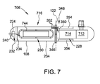
- FIG. 7 is a cross-sectional view of another alternative subsea boosting module 706 for use in system 100 (shown in FIG. 1 ).
- Subsea boosting module 706 is similar to subsea boosting module 606.
- Subsea boosting module 706 includes power components 716, electric motor 714, and fluid pump 712.
- Power components 716 include a single power converter 744.
- Subsea boosting module 706 does not include a separate transformer 226. Rather, power converter 744 may be an isolated power converter and/or electric motor 714 may have electric insulation suitable for use without a transformer.
- FIG. 8 is a diagram of an exemplary subsea boosting system 800 including an assembly 104 of three subsea boosting modules 306 (shown in FIG. 3 ).
- assembly 104 may be formed from subsea boosting modules 206, 406, 506, 606, and/or 706.
- Subsea boosting modules 306 are electrically connected in series and are connected in parallel fluid communication. The parallel fluid input is shown by input flows 856 and the parallel fluid output is shown by output flows 858.
- subsea boosting modules 306 are connected in series, in multiple stages, and/or in any other suitable configuration.
- FIG. 9 is a block diagram of a method 900 of producing a subsea boosting system for use with a DC power system, such as system 100 or 700.
- Method 900 may be used to produce a subsea boosting system with a first power rating.
- the method includes electrically coupling 902 together a plurality of subsea boosting modules (such as subsea boosting modules 106, 206, 306, 406, 506, or 606).
- Each subsea modules has a second power rating that is less than the first power rating.
- Each boosting module includes a fluid pump, an electric motor, and a plurality of power components.
- the fluid pumps of the subsea boosting modules are coupled together in fluid communication with each other. Accordingly, a large boosting assembly with a first power rating is created from a plurality of smaller, lower power rated modules.
- each boosting module includes any other suitable fluid pump.
- FIG. 10 is a schematic block diagram of subsea boosting system 1000 powered by an alternating current (AC) power source 1002.
- AC power source 1002 is a land based AC power grid.
- AC power source 1002 may be a sea platform based AC power source, an AC/AC power converter (land or platform based), or any other suitable AC power source.
- AC power source 1002 is a high voltage AC power source.
- AC power source 1002 may be a medium voltage AC power source followed by a step up transformer.
- AC power source 1002 provides up to several tens of kilovolt (kV) AC output.
- kV kilovolt
- AC power source 1002 provides up to a sixty kV AC output.
- AC power source 1002 provides any other suitable high voltage AC output that enables operation of subsea boosting system 1000 as described herein.
- AC power source 1002 is coupled to a step down transformer 1003.
- Step down transformer 1003 reduces the magnitude of the voltage received from AC power source 1002. In one example, step down transformer 1003 reduces the AC voltage from about one hundred kV to about thirty-six kV. In other embodiments, step down transformer 1003 reduces the AC voltage from AC power source to any other suitable high voltage AC output that enables operation of subsea boosting system 1000 as described herein.
- the reduced AC voltage output by step down transformer 1003 is coupled to a subsea boosting assembly 1004 through a subsea switchgear assembly 1007.
- Subsea switchgear assembly 1007 provides electrical protection and control over distribution of power to subsea boosting assembly 1004.
- Subsea switchgear assembly 1007 may include a plurality of circuit breakers, or other circuit protection devices (not shown in FIG. 10 ).
- Subsea boosting assembly 1004 includes multiple subsea boosting modules 1006 electrically coupled together, mechanically coupled together, and coupled together in fluid communication with each other. Subsea boosting modules 1006 are electrically coupled together in parallel through subsea switchgear 1007.
- Subsea boosting modules 1006 are mechanically coupled together by attachment to each other directly or indirectly using, for example, welding, fasteners, straps, or any other suitable mechanical connection.
- assembly 1004 includes four subsea boosting modules 1006.
- assembly 1004 may include more or fewer (including one) subsea boosting modules 1006.
- the number of subsea boosting modules 1006 is generally selected to provide an assembly 1004 with the desired pumping power.
- each module 1006 may be a smaller size than desired total pumping power.
- Each subsea boosting module 1006 includes a housing 1008 defining an interior 1010.
- a fluid pump 1012 is disposed within interior 1010 of housing 1008.
- An electric motor 1014 is disposed within interior 1010 of housing 1008 and is coupled to fluid pump 1012 to drive fluid pump 1012.
- Fluid pump 1012 and electric motor 1014 may be any suitable fluid pump and motor for driving the selected fluid pump.
- Fluid pump 1012, alone or in combination with motor 1014 may be a fluid pump, a compressor, a fan, or any other suitable device for transferring or manipulating a liquid, a gas, or any other fluid.
- fluid pump 1012 may be any process pump suitable for use in a subsea boosting system.
- Electric motor 1014 may be a single phase motor or a multiphase motor. The combination of electric motor 1014 and fluid pump 1012 will have a smaller power rating (in, e.g., MVA) than the complete subsea boosting system 1000 and a comparable single pump boosting system.
- Power components 1016 are disposed within interior 1010 of housing 1008 to provide power to electric motor 1014. Power components 1016 generally include all components needed to power electric motor 1014 to drive fluid pump 1012 from the AC power received from source 1002.
- power components 1016 include one or more AC to AC (AC/AC) power converters (not shown in FIG. 10 ).
- the AC/AC power converters may be any suitable isolated or non-isolated AC/AC power converters.
- the AC/AC power converters may each include any suitable number of converter stages.
- an AC/AC power converter may be a single stage AC/AC converter.
- an AC/AC power converter may include an AC to DC power converter stage, followed by one or more DC/DC converter stages and a DC/AC converter stage.
- power components 1016 include one or more transformers (not shown in FIG. 10 ). The transformers may be separate transformers and/or may be a part of one or more stages of the AC/AC power converter.
- subsea boosting modules 1006 may include a switchgear module coupled between the AC power input and power components 1016.
- the switchgear module permits selective disconnecting of the subsea boosting module 1006 from AC power source 1002 and the other subsea boosting modules 1006, e.g., in response to a received instruction, in response to a detected condition etc.
- the switchgear module permits selective coupling of one or more components of the power components 1016 to AC power source 1002.
- Some embodiments include one or more cooling systems within housing 1008 of subsea boosting modules 1006. Cooling systems may include active and/or passive cooling systems used to cool fluid pump 1012, electric motor 1014, and/or power components 1016. In some embodiments, active cooling systems include one or more cooling pumps powered by electric motor 1014.
- housing 1008 of subsea boosting module 1006 defines two or more interior chambers (not shown in FIG. 10 ). Fluid pump 1012 and electric motor 1014 are disposed in one chamber of subsea boosting module 1006, while power components 1016 and additional components are disposed in one or more other chambers of subsea boosting module. In another example embodiment, fluid pump 1012 and electric motor 1014 are disposed in a chamber of subsea boosting module 1006 that is configured to maintain substantially the same pressure within the chamber as the ambient pressure outside housing 1008. Power components 1016 are disposed in a different chamber of subsea boosting module 1006 that is configured to maintain a substantially constant pressure within the chamber without regard to the ambient pressure outside housing 1008.
- power components 1016 are disposed in a chamber of subsea boosting module 1006 that is configured to maintain a substantially constant pressure of one atmosphere within the chamber. Additional components may be housed within the same chamber as power components 1016 or in a different chamber, which may maintain a constant pressure or maintain a pressure the same as the ambient pressure around housing 1008.
- Fluid pumps 1012 of subsea boosting modules 1006 may be coupled together in fluid communication with each other in series or in parallel.
- bypass valves and/or recirculation valves may be used to permit selective bypassing of selected subsea boosting module(s) 1006, e.g., without limitation, when one subsea boosting module 1006 is blocked and/or has a fault.
- FIGS. 11-13 are cross sectional views of exemplary embodiments of subsea boosting modules for use as subsea boosting modules 1006 in system 1000 (shown in FIG. 10 ). Similar components in FIGS. 11-13 are identified with the same reference numbers.
- FIG. 11 is a cross-sectional view of an exemplary subsea boosting module 1106 for use in the system 1000.
- Subsea boosting module 1106, shown in FIG. 11 includes a switchgear module 1124, power components 1016, electric motor 1014, and fluid pump 1012.
- Housing 1008 defines three chambers 1128, 1130, and 1132 separated by dividers 1134, which may also be referred to as bulkheads. Chambers 1128 and 1132 are configured to maintain substantially the same pressure as the ambient pressure outside of housing 1008, while chamber 1130 is configured to maintain a substantially constant pressure (e.g., about 101.325 kilopascals) regardless of the ambient pressure outside housing 1008.
- a fluid inlet 1136 and a fluid outlet 1138 are coupled to housing 1008 to permit fluid communication to fluid pump 1012.
- Interface 1140 (which may also be referred to as an input) couples AC power from AC power source 1002 (shown in FIG. 10 ) to subsea boosting module 1106 (and more specifically to switchgear module 1124).
- Interface 1140 is a wet mateable connector (also sometimes referred to as a wet mateable penetrator).
- power components 1016 include three power converters 1144 (one of which is not shown).
- the exemplary power converters 1144 are AC/AC converters.
- Power converters 1144 are configured to receive AC power from source 1002 through interface 1140 and switchgear module 1124, and to output AC power to motor 1014 (which is a nine phase motor in this embodiment) through three dry mateable connectors 1145.
- all three power converters 1144 are needed to provide the desired power output for operation of electric motor 1014.
- a single power converter 1144 or two power converters 1144 may be sufficient to power electric motor 1014, and the second and/or third power converter 1144 may be one or more redundant power converters 1144.
- FIG. 12 is a cross-sectional view of an alternative subsea boosting module 1206 for use in system 1000 (shown in FIG. 10 ).
- subsea boosting module 1206 is designed for connection to a multi-winding transformer.
- Electric motor 1014 is a three phase motor in this embodiment, and a single dry-mateable connector 1145 is used.
- Subsea boosting module 1206 includes a flange 1246. Flange 1246 separates chamber 1128 from chamber 1130.
- one or more of dividers 1134 are used in lieu of flanges 1246.
- one or more flanges 1246 are used in lieu of dividers 1134.
- Subsea boosting module 1206 includes a cooling system 1248 for cooling power converters 1144 and electric motor 1014.
- Cooling system 1248 includes a pump 1250 for pumping coolant through cooling system 1248.
- Pump 1250 is rotatably coupled to and powered by electric motor 1014.
- Cooling system 1248 pumps coolant through coolant pipes 1252 to power converters 1144, and pumps coolant through coiled tubes 1254 for external cooling of electric motor 1014.
- motor 1014 and power components 1016 may be cooled using separate cooling systems 1248.
- some embodiments may include additional cooling components. For example, additional external coils may be added around power converters 1144 to provide additional external cooling.
- FIG. 13 is a cross-sectional view of another alternative subsea boosting module 1306 for use in system 1000 (shown in FIG. 10 ).
- Subsea boosting module 1306 is smaller than subsea boosting modules 1106 and 1206.
- Subsea boosting module 1306 includes power components 1316, electric motor 1314 and fluid pump 1312.
- Power components 1316 include a single power converter 1144.
- Electric motor 1314 and fluid pump 1312 are rated for a lower power than electric motor 1014 and fluid pump 1012 in subsea boosting modules 1106 and 1206, but are otherwise similar. Because motor 1314 and pump 1312 require less power, only a single power converter 1144 is needed to power electric motor 1014 in subsea boosting module 1306.
- FIG. 14 is a diagram of an exemplary subsea boosting system 1400 including an assembly 1004 of three subsea boosting modules 1306 (shown in FIG. 13 ).
- assembly 1004 may be formed from subsea boosting modules 1106 and/or 1206.
- Subsea boosting modules 1306 are electrically connected in parallel and are connected in parallel fluid communication.
- the parallel fluid input is shown by input flows 1456 and the parallel fluid output is shown by output flows 1458.
- there may be electrical cross-ties between the modules 1306 so that any motor-pump of any module 1306 can be driven by any of the other modules 1306.
- This provides matrixed power connectivity so that any module can drive any pump motor. Rather than an "all or nothing" approach to availability, the matrixed configuration allows partial capability/availability so that power draw can be matched to what is required thus improving overall system up-time.
- FIG. 15 is a block diagram of a method 1500 of producing a subsea boosting system for use with an AC power system, such as system 1000 or 1400.
- Method 1800 may be used to produce a subsea boosting system with a first power rating.
- the method includes electrically coupling 1502 together a plurality of subsea boosting modules (such as subsea boosting modules 1006, 1106, 1206, or 1306).
- Each subsea modules has a second power rating that is less than the first power rating.
- Each boosting module includes a fluid pump, an electric motor, and a plurality of power components.
- the fluid pumps of the subsea boosting modules are coupled together in fluid communication with each other. Accordingly, a large boosting assembly with a first power rating is created from a plurality of smaller, lower power rated modules.
- the exemplary subsea boosting modules described herein generally include only a single wet mateable connector and the number of critical pressure tolerant connections and penetrations is substantially minimized.
- Each cylindrical section of a module is a separate functional module, which may be separately assembled and tested.
- Auxiliary systems and cooling are shared between mechanical and electrical modules in some embodiments. After modules are assembled and tested, they may be mechanically attached together (such as by welding) to create a robust subsea vessel.
- the number of modules and/or chambers within a module may be varied to meet power demand requirements of the user.
- the modular approach implies relative lower size and mass per module and thus shipping or installation equipment capability limits are avoided.
- the weight limit of locally available installation vessels may easily be exceeded by a conventional high power boosting station.
Landscapes
- Engineering & Computer Science (AREA)
- Geology (AREA)
- Mining & Mineral Resources (AREA)
- Life Sciences & Earth Sciences (AREA)
- Physics & Mathematics (AREA)
- General Life Sciences & Earth Sciences (AREA)
- Fluid Mechanics (AREA)
- Environmental & Geological Engineering (AREA)
- Geochemistry & Mineralogy (AREA)
- Microelectronics & Electronic Packaging (AREA)
- Mechanical Engineering (AREA)
- General Engineering & Computer Science (AREA)
- Thermal Sciences (AREA)
- Inverter Devices (AREA)
Abstract
Description
- This description relates to subsea boosting, more particularly, to systems and methods for subsea boosting in high-voltage direct current (HVDC) and/or high-voltage alternating current (HVAC) transmission and distribution systems.
- As oil and gas fields in shallow waters diminish, producers are tapping offshore fields in deeper waters with oil installations that operate far below the surface of the sea. The typical equipment for such subsea oil recovery and production include gas compressors and various pumps for multiple functions. Electric variable speed drive (VSD) and motor systems are one way to power such equipment directly under the deep water. Therefore, the delivery of electric power from a remote onshore utility grid or power generation is important to secure a reliable production and processing of oil and gas in subsea locations. Typically, the transmission power requirement is up to several hundred megawatts for medium to large oil/gas fields.
- Alternating current (AC) transmission and distribution systems are one technology suited for delivery of power to subsea locations. Such systems typically deliver AC power from a platform or onshore location to a large subsea transformer through a large power cable. Power is transferred from the subsea transformer to subsea AC switchgear through another power cable. The subsea AC switchgear feeds AC power to one or more subsea VSDs via yet another cable. The VSDs each provide variable AC power to electric motors via a power cable. The connections between components in subsea AC distribution systems typically require wet mateable connectors, which are significantly more complex and expensive than dry mateable connectors. In addition, the power requirement and thus the size of components in subsea boosting systems has generally increased over time. Some known systems utilize three to five megavolt-ampere (MVA) pumps, each of which may weigh more than ten tons. Other components in known subsea boosting systems and/or AC transmission and distribution systems are also very large and/or heavy. Moreover, some AC transmission and distribution topologies face technical challenges, which become more significant when transmission distance is in excess of fifty kilometers.
- In one embodiment, a subsea boosting module for use with an alternating current (AC) power system includes a housing defining at least one interior chamber. A fluid pump is disposed within the interior chamber. An electric motor is disposed within the interior chamber and drivingly coupled to the fluid pump. A plurality of power components is disposed within the interior chamber to deliver power to the electric motor.
- In another embodiment, a subsea boosting system for use with an alternating current (AC) power system includes a plurality of subsea boosting modules. Each subsea boosting module includes a fluid pump, an electric motor drivingly coupled to the fluid pump, and a plurality of power components configured to deliver power to the electric motor. The plurality of subsea boosting modules are electrically coupled together in parallel. The fluid pumps of the plurality of subsea modules are coupled together in fluid communication.
- In yet another embodiment, a method of producing a subsea boosting system for use with an alternating current (AC) power system is described. The subsea boosting system has a first power rating. The method includes electrically coupling together a plurality of subsea boosting modules, each of which includes a fluid pump, an electric motor, and a plurality of power components. The subsea boosting modules each have a second power rating less than the first power rating. The method includes coupling together in fluid communication the fluid pumps of the subsea boosting modules.
- These and other features, aspects, and advantages of the present disclosure will become better understood when the following detailed description is read with reference to the accompanying drawings in which like characters represent like parts throughout the drawings, wherein:
-
FIG. 1 is a schematic block diagram of subsea boosting system powered by a direct current (DC) power source; -
FIG. 2 is a cross-sectional view of an exemplary subsea boosting module for use in the system shown inFIG. 1 ; -
FIG. 3 is a cross-sectional view of an alternative subsea boosting module for use in the system shown inFIG. 1 ; -
FIG. 4 is a cross-sectional view of a another alternative subsea boosting module for use in the system shown inFIG. 1 ; -
FIG. 5 is a cross-sectional view of yet another alternative subsea boosting module for use in the system shown inFIG. 1 ; -
FIG. 6 is a cross-sectional view of a further alternative subsea boosting module for use in the system shown inFIG. 1 ; -
FIG. 7 is a cross-sectional view of a yet another alternative subsea boosting module for use in the system shown inFIG. 1 ; -
FIG. 8 is a diagram of a subsea boosting system including an assembly of three of the subsea boosting modules shown inFIG. 3 ; -
FIG. 9 is block diagram of a method of producing a subsea boosting system for use with a DC power system; -
FIG. 10 is a schematic block diagram of subsea boosting system powered by an alternating current (AC) power source; -
FIG. 11 is a cross-sectional view of an exemplary subsea boosting module for use in the system shown inFIG. 10 ; -
FIG. 12 is a cross-sectional view of an alternative subsea boosting module for use in the system shown inFIG. 10 ; -
FIG. 13 is a cross-sectional view of a another alternative subsea boosting module for use in the system shown inFIG. 10 ; -
FIG. 14 is a diagram of a subsea boosting system including an assembly of four of the subsea boosting modules shown inFIG. 13 ; and -
FIG. 15 is block diagram of a method of producing a subsea boosting system for use with an AC power system. - Unless otherwise indicated, the drawings provided herein are meant to illustrate features of embodiments of the disclosure. These features are believed to be applicable in a wide variety of systems comprising one or more embodiments of the disclosure. As such, the drawings are not meant to include all conventional features known by those of ordinary skill in the art to be required for the practice of the embodiments disclosed herein.
- In the following specification and the claims, reference will be made to a number of terms, which shall be defined to have the following meanings.
- The singular forms "a", "an", and "the" include plural references unless the context clearly dictates otherwise.
- "Optional" or "optionally" means that the subsequently described event or circumstance may or may not occur, and that the description includes instances where the event occurs and instances where it does not.
- Approximating language, as used herein throughout the specification and claims, may be applied to modify any quantitative representation that could permissibly vary without resulting in a change in the basic function to which it is related. Accordingly, a value modified by a term or terms, such as "about" and "substantially", are not to be limited to the precise value specified. In at least some instances, the approximating language may correspond to the precision of an instrument for measuring the value. Here and throughout the specification and claims, range limitations may be combined and/or interchanged, such ranges are identified and include all the sub-ranges contained therein unless context or language indicates otherwise.
- Embodiments of the present disclosure relate to subsea boosting and systems and methods for subsea boosting in a high-voltage direct current (HVDC) and high-voltage alternating current (HVAC) transmission and distribution system. More particularly, embodiments of this disclosure relate to a modular, vertically integrated system architecture for subsea boosting, in which one or more subsea modules are combined to form a subsea boosting system. Each of the subsea modules integrates a motor, pump and electronic power components into a single module. The subsea modules are compartmentalized pressure vessels, with each compartment being assembled to the module as its equipment is installed. The vessel shape is conducive to handling different pressures in different compartments, while limiting the cross section of the module. Some, exemplary embodiments substantially minimize the number of power penetrators utilized in the subsea boosting module, resulting in higher reliability and lower costs. The modular approach allows subsea boosting systems to be built to match a desired system power, as well as maintaining partial availability to reduce system down-time. The subsea boosting modules generally have a lower size and mass per module than the large components of a non-modularized system.
- The following description refers to the accompanying drawings, in which, in the absence of a contrary representation, the same numbers in different drawings represent similar elements.
-
FIG. 1 is a schematic block diagram of subsea boostingsystem 100 powered by a direct current (DC)power source 102. In the exemplary embodiment,DC power source 102 is a platform based alternating current (AC) to DC power converter that converts AC power from an AC power source, e.g., without limitation, an AC power grid, to DC power. In other embodiments,DC power source 102 may be a land based DC power source, a DC power generator (land or platform based), or any other suitable DC power source.DC power source 102 is a high voltage DC power source. In the exemplary embodiment,DC power source 102 provides up to several tens of kilovolt (kV) DC output. In an embodiment,DC power source 102 provides up to thirty kV DC output. In other embodiments, DC power source provides any other suitable high voltage DC output that enables operation of subsea boostingsystem 100 as described herein. - A subsea boosting
assembly 104 is electrically coupled to and receives DC power fromDC power source 102 via a two wireumbilical cable 105.Subsea boosting assembly 104 includes multiple subsea boostingmodules 106 electrically coupled together, mechanically coupled together, and coupled together in fluid communication with each other. Subsea boostingmodules 106 are mechanically coupled together by attachment to each other directly or indirectly using, for example, welding, fasteners, straps, or any other suitable mechanical connection. In the illustrated embodiment,assembly 104 includes four subsea boostingmodules 106. In other embodiments,assembly 104 may include more or fewer (including one)subsea boosting modules 106. The number of subsea boostingmodules 106 is generally selected to provide anassembly 104 with the desired pumping power. Thus, eachmodule 106 may be a smaller size than desired total pumping power. For example, rather than utilizing a single, large six MVA pump, three smaller subsea boostingmodules 106, each rated at two MVA, may be utilized. - Each subsea boosting
module 106 includes ahousing 108 defining an interior 110. Afluid pump 112 is disposed withininterior 110 ofhousing 108. Anelectric motor 114 is disposed withininterior 110 ofhousing 108 and is coupled tofluid pump 112 to drivefluid pump 112.Fluid pump 112 andelectric motor 114 may be any suitable fluid pump and motor for driving the selected fluid pump.Fluid pump 112, alone or in combination withmotor 114, may be a fluid pump, a compressor, a fan, or any other suitable device for transferring or manipulating a liquid, a gas, or any other fluid. Moreover,fluid pump 112 may be any process pump suitable for use in a subsea boosting system. The combination ofelectric motor 114 andfluid pump 112 will have a smaller power rating (in, e.g., MVA) than the complete subsea boostingsystem 100 and a comparable single pump boosting system. -
Power components 116 are disposed withininterior 110 ofhousing 108 to provide power toelectric motor 114.Power components 116 generally include all components needed to powerelectric motor 114 to drivefluid pump 112 from the DC power received fromsource 102. In some embodiments,power components 116 include one or more DC to AC (DC/AC) power converters (not shown inFIG. 1 ). The DC/AC power converters may be any suitable isolated or non-isolated DC/AC power converters. Moreover, the DC/AC power converters may each include any suitable number of converter stages. For example, a DC/AC power converter may be a single stage DC/AC converter. Alternatively, a DC/AC power converter may include one or more DC to DC power converter stages, followed by a DC/AC converter stage. In some embodiments,power components 116 include one or more transformers (not shown inFIG. 1 ) for isolating aDC side 118 ofsystem 100 from anAC side 120 of system 100 (separated inFIG. 1 by an isolation line 122). The transformers may be separate transformers and/or may be a part of one or more stages of the DC/AC power converter. - Subsea boosting
modules 106 are electrically coupled together in series. One wire ofumbilical cable 105 is connected to the first subsea boostingmodule 106 in the series, while the second wire ofumbilical cable 105 is connected to the last subsea boostingmodule 106 in the series. - Various additional components and/or systems (not shown in
FIG. 1 ) may be included in some embodiments of subsea boostingmodules 106. For example, subsea boostingmodules 106 may include a bypass module coupled between the DC power input andpower components 116. The bypass module permits selective bypassing of the subsea boostingmodule 106 by electrically disconnecting it fromDC power source 102 and the othersubsea boosting modules 106, e.g., in response to a received instruction, in response to a detected condition etc. Moreover, in some embodiments, the bypass module permits selective coupling of one or more components of thepower components 116 toDC power source 102 and/or other subsea boostingmodules 106. Some embodiments include one or more cooling systems withinhousing 108 of subsea boostingmodules 106. Cooling systems may include active and/or passive cooling systems used to coolfluid pump 112,electric motor 114, and/orpower components 116. In some embodiments, active cooling systems include one or more cooling pumps powered byelectric motor 114. - In some embodiments,
housing 108 of subsea boostingmodule 106 defines two or more interior chambers (not shown inFIG. 1 ).Fluid pump 112 andelectric motor 114 are disposed in one chamber of subsea boostingmodule 106, whilepower components 116 and additional components are disposed in one or more other chambers of subsea boosting module. In another example embodiment,fluid pump 112 andelectric motor 114 are disposed in a chamber of subsea boostingmodule 106 that is configured to maintain substantially the same pressure within the chamber as the ambient pressure outsidehousing 108.Power components 116 are disposed in a different chamber of subsea boostingmodule 106 that is configured to maintain a substantially constant pressure within the chamber without regard to the ambient pressure outsidehousing 108. In a particular embodiment,power components 116 are disposed in a chamber of subsea boostingmodule 106 that is configured to maintain a substantially constant pressure of one atmosphere within the chamber. Additional components may be housed within the same chamber aspower components 116 or in a different chamber, which may maintain a constant pressure or maintain a pressure the same as the ambient pressure aroundhousing 108. - Fluid pumps 112 of subsea boosting
modules 106 may be coupled together in fluid communication with each other in series or in parallel. When coupled together in series, bypass valves and/or recirculation valves may be used to permit selective bypassing of selected subsea boosting module(s) 106, e.g., without limitation, when one subsea boostingmodule 106 is blocked and/or has a fault. -
FIGS. 2-7 are cross sectional views of exemplary embodiments of subsea boosting modules for use as subsea boostingmodules 106 in system 100 (shown inFIG. 1 ). Similar components inFIGS. 2-7 are identified with the same reference numbers. -
FIG. 2 is a cross-sectional view of an exemplary subsea boostingmodule 206 for use in thesystem 100.Subsea boosting module 206, shown inFIG. 2 , includes abypass module 224,power components 116, atransformer 226,electric motor 114, andfluid pump 112. -
Housing 108 defines threechambers dividers 234, which may also be referred to as bulkheads.Chambers housing 108, whilechamber 230 is configured to maintain a substantially constant pressure (e.g., about 101.325 kilopascals) regardless of the ambient pressure outsidehousing 108. Afluid inlet 236 and afluid outlet 238 are coupled tohousing 108 to permit fluid communication tofluid pump 112. - Interface 240 (which may also be referred to as an input) couples DC power from DC power source 102 (shown in
FIG. 1 ) to subsea boosting module 206 (and more specifically to bypass module 224).Subsea boosting module 206 may also be coupled in series with other subsea boostingmodules 206 viainterface 240. Thuswires 242 may be wires interconnecting subsea boostingmodule 206 with other subsea boostingmodules 206, and/or may be one or both wires from umbilical cable 105 (shown inFIG. 1 ).Interface 240 is configured for a wet mateable connection, i.e., it includes a wet mateable connector, withwires 242. - In subsea boosting
module 206,power components 116 include three power converters 244 (one of which is not shown). Theexemplary power converters 244 are non-isolated DC/AC converters.Power converters 244 are configured to receive DC power fromsource 102 throughinterface 240 andbypass module 224, and to output AC power tomotor 114 throughtransformer 226. In the exemplary embodiment, all threepower converters 244 are needed to provide the desired power output for operation ofelectric motor 114. In other embodiments asingle power converter 244 or twopower converters 244 may be sufficient to powerelectric motor 114, and the second and/orthird power converter 244 may be one or moreredundant power converters 244. -
FIG. 3 is a cross-sectional view of an alternative subsea boostingmodule 306 for use in system 100 (shown inFIG. 1 ). In this embodiment,housing 108 defines anadditional chamber 345 in whichtransformer 226 is disposed.Subsea boosting module 306 includes aflange 346.Flange 346 separateschamber 228 fromchamber 345. In some embodiments, one or more ofdividers 234 are used in lieu offlanges 346. Alternatively, one ormore flanges 346 are used in lieu ofdividers 234. -
Subsea boosting module 306 includes acooling system 348 for coolingpower converters 244 andelectric motor 114.Cooling system 348 includes apump 350 for pumping coolant throughcooling system 348.Pump 350 is rotatably coupled to and powered byelectric motor 114.Cooling system 348 pumps coolant throughcoolant pipes 352 topower converters 244, and pumps coolant through coiledtubes 354 for external cooling ofelectric motor 114. In other embodiments,motor 114 andpower components 116 may be cooled usingseparate cooling systems 348. Moreover, some embodiments may include additional cooling components. For example, additional external coils may be added aroundpower converters 244 to provide additional external cooling. -
FIG. 4 is a cross-sectional view of another alternative subsea boostingmodule 406 for use in system 100 (shown inFIG. 1 ). In this embodiment,motor 114 is replaced with anelectric motor 414 that includes sufficiently rated electrical insulation for high voltage to ground such that a transformer is not needed. -
FIG. 5 is a cross-sectional view of yet another alternative subsea boostingmodule 506 for use in system 100 (shown inFIG. 1 ). In subsea boostingmodule 506,power converters 244 are replaced withpower converters 544.Power converters 544 are isolated power converters that includeintegrated transformers 556. Thus, a separate transformer is not utilized. -
FIG. 6 is a cross-sectional view of another alternative subsea boostingmodule 606 for use in system 100 (shown inFIG. 1 ).Subsea boosting module 606 is smaller than subsea boostingmodules Subsea boosting module 606 includespower components 616,electric motor 614 andfluid pump 612.Power components 616 include asingle power converter 244.Electric motor 614 andfluid pump 612 are rated for a lower power thanelectric motor 114 andfluid pump 112 in subsea boostingmodules motor 614 and pump 612 require less power, only asingle power converter 244 is needed to powerelectric motor 114 in subsea boostingmodule 606. -
FIG. 7 is a cross-sectional view of another alternative subsea boostingmodule 706 for use in system 100 (shown inFIG. 1 ).Subsea boosting module 706 is similar to subsea boostingmodule 606.Subsea boosting module 706 includespower components 716,electric motor 714, andfluid pump 712.Power components 716 include asingle power converter 744.Subsea boosting module 706 does not include aseparate transformer 226. Rather,power converter 744 may be an isolated power converter and/orelectric motor 714 may have electric insulation suitable for use without a transformer. -
FIG. 8 is a diagram of an exemplary subsea boostingsystem 800 including anassembly 104 of three subsea boosting modules 306 (shown inFIG. 3 ). In other embodiments,assembly 104 may be formed from subsea boostingmodules modules 306 are electrically connected in series and are connected in parallel fluid communication. The parallel fluid input is shown by input flows 856 and the parallel fluid output is shown by output flows 858. In other embodiments, subsea boostingmodules 306 are connected in series, in multiple stages, and/or in any other suitable configuration. -
FIG. 9 is a block diagram of amethod 900 of producing a subsea boosting system for use with a DC power system, such assystem 100 or 700.Method 900 may be used to produce a subsea boosting system with a first power rating. The method includes electrically coupling 902 together a plurality of subsea boosting modules (such as subsea boostingmodules -
FIG. 10 is a schematic block diagram of subsea boostingsystem 1000 powered by an alternating current (AC)power source 1002. In the exemplary embodiment,AC power source 1002 is a land based AC power grid. In other embodiments,AC power source 1002 may be a sea platform based AC power source, an AC/AC power converter (land or platform based), or any other suitable AC power source.AC power source 1002 is a high voltage AC power source. Alternatively,AC power source 1002 may be a medium voltage AC power source followed by a step up transformer. In the exemplary embodiment,AC power source 1002 provides up to several tens of kilovolt (kV) AC output. In an embodiment,AC power source 1002 provides up to a sixty kV AC output. In other embodiments,AC power source 1002 provides any other suitable high voltage AC output that enables operation of subsea boostingsystem 1000 as described herein. -
AC power source 1002 is coupled to a step downtransformer 1003. Step downtransformer 1003 reduces the magnitude of the voltage received fromAC power source 1002. In one example, step downtransformer 1003 reduces the AC voltage from about one hundred kV to about thirty-six kV. In other embodiments, step downtransformer 1003 reduces the AC voltage from AC power source to any other suitable high voltage AC output that enables operation of subsea boostingsystem 1000 as described herein. - The reduced AC voltage output by step down
transformer 1003 is coupled to a subsea boostingassembly 1004 through asubsea switchgear assembly 1007.Subsea switchgear assembly 1007 provides electrical protection and control over distribution of power to subsea boostingassembly 1004.Subsea switchgear assembly 1007 may include a plurality of circuit breakers, or other circuit protection devices (not shown inFIG. 10 ).Subsea boosting assembly 1004 includes multiple subsea boostingmodules 1006 electrically coupled together, mechanically coupled together, and coupled together in fluid communication with each other. Subsea boostingmodules 1006 are electrically coupled together in parallel throughsubsea switchgear 1007. Subsea boostingmodules 1006 are mechanically coupled together by attachment to each other directly or indirectly using, for example, welding, fasteners, straps, or any other suitable mechanical connection. In the illustrated embodiment,assembly 1004 includes four subsea boostingmodules 1006. In other embodiments,assembly 1004 may include more or fewer (including one)subsea boosting modules 1006. The number of subsea boostingmodules 1006 is generally selected to provide anassembly 1004 with the desired pumping power. Thus, eachmodule 1006 may be a smaller size than desired total pumping power. - Each subsea boosting
module 1006 includes ahousing 1008 defining an interior 1010. Afluid pump 1012 is disposed within interior 1010 ofhousing 1008. Anelectric motor 1014 is disposed within interior 1010 ofhousing 1008 and is coupled tofluid pump 1012 to drivefluid pump 1012.Fluid pump 1012 andelectric motor 1014 may be any suitable fluid pump and motor for driving the selected fluid pump.Fluid pump 1012, alone or in combination withmotor 1014, may be a fluid pump, a compressor, a fan, or any other suitable device for transferring or manipulating a liquid, a gas, or any other fluid. Moreover,fluid pump 1012 may be any process pump suitable for use in a subsea boosting system.Electric motor 1014 may be a single phase motor or a multiphase motor. The combination ofelectric motor 1014 andfluid pump 1012 will have a smaller power rating (in, e.g., MVA) than the complete subsea boostingsystem 1000 and a comparable single pump boosting system. -
Power components 1016 are disposed within interior 1010 ofhousing 1008 to provide power toelectric motor 1014.Power components 1016 generally include all components needed to powerelectric motor 1014 to drivefluid pump 1012 from the AC power received fromsource 1002. In some embodiments,power components 1016 include one or more AC to AC (AC/AC) power converters (not shown inFIG. 10 ). The AC/AC power converters may be any suitable isolated or non-isolated AC/AC power converters. Moreover, the AC/AC power converters may each include any suitable number of converter stages. For example, an AC/AC power converter may be a single stage AC/AC converter. Alternatively, an AC/AC power converter may include an AC to DC power converter stage, followed by one or more DC/DC converter stages and a DC/AC converter stage. In some embodiments,power components 1016 include one or more transformers (not shown inFIG. 10 ). The transformers may be separate transformers and/or may be a part of one or more stages of the AC/AC power converter. - Various additional components and/or systems (not shown in
FIG. 10 ) may be included in some embodiments of subsea boostingmodules 1006. For example, subsea boostingmodules 1006 may include a switchgear module coupled between the AC power input andpower components 1016. The switchgear module permits selective disconnecting of the subsea boostingmodule 1006 fromAC power source 1002 and the othersubsea boosting modules 1006, e.g., in response to a received instruction, in response to a detected condition etc. Moreover, in some embodiments, the switchgear module permits selective coupling of one or more components of thepower components 1016 toAC power source 1002. Some embodiments include one or more cooling systems withinhousing 1008 of subsea boostingmodules 1006. Cooling systems may include active and/or passive cooling systems used to coolfluid pump 1012,electric motor 1014, and/orpower components 1016. In some embodiments, active cooling systems include one or more cooling pumps powered byelectric motor 1014. - In some embodiments,
housing 1008 of subsea boostingmodule 1006 defines two or more interior chambers (not shown inFIG. 10 ).Fluid pump 1012 andelectric motor 1014 are disposed in one chamber of subsea boostingmodule 1006, whilepower components 1016 and additional components are disposed in one or more other chambers of subsea boosting module. In another example embodiment,fluid pump 1012 andelectric motor 1014 are disposed in a chamber of subsea boostingmodule 1006 that is configured to maintain substantially the same pressure within the chamber as the ambient pressure outsidehousing 1008.Power components 1016 are disposed in a different chamber of subsea boostingmodule 1006 that is configured to maintain a substantially constant pressure within the chamber without regard to the ambient pressure outsidehousing 1008. In a particular embodiment,power components 1016 are disposed in a chamber of subsea boostingmodule 1006 that is configured to maintain a substantially constant pressure of one atmosphere within the chamber. Additional components may be housed within the same chamber aspower components 1016 or in a different chamber, which may maintain a constant pressure or maintain a pressure the same as the ambient pressure aroundhousing 1008. - Fluid pumps 1012 of subsea boosting
modules 1006 may be coupled together in fluid communication with each other in series or in parallel. When coupled together in series, bypass valves and/or recirculation valves may be used to permit selective bypassing of selected subsea boosting module(s) 1006, e.g., without limitation, when one subsea boostingmodule 1006 is blocked and/or has a fault. -
FIGS. 11-13 are cross sectional views of exemplary embodiments of subsea boosting modules for use as subsea boostingmodules 1006 in system 1000 (shown inFIG. 10 ). Similar components inFIGS. 11-13 are identified with the same reference numbers. -
FIG. 11 is a cross-sectional view of an exemplary subsea boostingmodule 1106 for use in thesystem 1000.Subsea boosting module 1106, shown inFIG. 11 , includes aswitchgear module 1124,power components 1016,electric motor 1014, andfluid pump 1012. -
Housing 1008 defines threechambers dividers 1134, which may also be referred to as bulkheads.Chambers housing 1008, whilechamber 1130 is configured to maintain a substantially constant pressure (e.g., about 101.325 kilopascals) regardless of the ambient pressure outsidehousing 1008. Afluid inlet 1136 and afluid outlet 1138 are coupled tohousing 1008 to permit fluid communication tofluid pump 1012. - Interface 1140 (which may also be referred to as an input) couples AC power from AC power source 1002 (shown in
FIG. 10 ) to subsea boosting module 1106 (and more specifically to switchgear module 1124).Interface 1140 is a wet mateable connector (also sometimes referred to as a wet mateable penetrator). - In subsea boosting
module 1106,power components 1016 include three power converters 1144 (one of which is not shown). Theexemplary power converters 1144 are AC/AC converters.Power converters 1144 are configured to receive AC power fromsource 1002 throughinterface 1140 andswitchgear module 1124, and to output AC power to motor 1014 (which is a nine phase motor in this embodiment) through three drymateable connectors 1145. In the exemplary embodiment, all threepower converters 1144 are needed to provide the desired power output for operation ofelectric motor 1014. In other embodiments asingle power converter 1144 or twopower converters 1144 may be sufficient to powerelectric motor 1014, and the second and/orthird power converter 1144 may be one or moreredundant power converters 1144. -
FIG. 12 is a cross-sectional view of an alternative subsea boostingmodule 1206 for use in system 1000 (shown inFIG. 10 ). In this embodiment, subsea boostingmodule 1206 is designed for connection to a multi-winding transformer.Electric motor 1014 is a three phase motor in this embodiment, and a single dry-mateable connector 1145 is used.Subsea boosting module 1206 includes aflange 1246.Flange 1246 separateschamber 1128 fromchamber 1130. In some embodiments, one or more ofdividers 1134 are used in lieu offlanges 1246. Alternatively, one ormore flanges 1246 are used in lieu ofdividers 1134. -
Subsea boosting module 1206 includes acooling system 1248 for coolingpower converters 1144 andelectric motor 1014.Cooling system 1248 includes apump 1250 for pumping coolant throughcooling system 1248.Pump 1250 is rotatably coupled to and powered byelectric motor 1014.Cooling system 1248 pumps coolant throughcoolant pipes 1252 topower converters 1144, and pumps coolant through coiledtubes 1254 for external cooling ofelectric motor 1014. In other embodiments,motor 1014 andpower components 1016 may be cooled usingseparate cooling systems 1248. Moreover, some embodiments may include additional cooling components. For example, additional external coils may be added aroundpower converters 1144 to provide additional external cooling. -
FIG. 13 is a cross-sectional view of another alternative subsea boostingmodule 1306 for use in system 1000 (shown inFIG. 10 ).Subsea boosting module 1306 is smaller than subsea boostingmodules Subsea boosting module 1306 includespower components 1316,electric motor 1314 andfluid pump 1312.Power components 1316 include asingle power converter 1144.Electric motor 1314 andfluid pump 1312 are rated for a lower power thanelectric motor 1014 andfluid pump 1012 in subsea boostingmodules motor 1314 and pump 1312 require less power, only asingle power converter 1144 is needed to powerelectric motor 1014 in subsea boostingmodule 1306. -
FIG. 14 is a diagram of an exemplary subsea boostingsystem 1400 including anassembly 1004 of three subsea boosting modules 1306 (shown inFIG. 13 ). In other embodiments,assembly 1004 may be formed from subsea boostingmodules 1106 and/or 1206. Subsea boostingmodules 1306 are electrically connected in parallel and are connected in parallel fluid communication. The parallel fluid input is shown byinput flows 1456 and the parallel fluid output is shown by output flows 1458. In some embodiments, there may be electrical cross-ties between themodules 1306 so that any motor-pump of anymodule 1306 can be driven by any of theother modules 1306. This provides matrixed power connectivity so that any module can drive any pump motor. Rather than an "all or nothing" approach to availability, the matrixed configuration allows partial capability/availability so that power draw can be matched to what is required thus improving overall system up-time. -
FIG. 15 is a block diagram of amethod 1500 of producing a subsea boosting system for use with an AC power system, such assystem modules - The exemplary subsea boosting modules described herein generally include only a single wet mateable connector and the number of critical pressure tolerant connections and penetrations is substantially minimized. Each cylindrical section of a module is a separate functional module, which may be separately assembled and tested. Auxiliary systems and cooling are shared between mechanical and electrical modules in some embodiments. After modules are assembled and tested, they may be mechanically attached together (such as by welding) to create a robust subsea vessel. Moreover, the number of modules and/or chambers within a module may be varied to meet power demand requirements of the user. The modular approach implies relative lower size and mass per module and thus shipping or installation equipment capability limits are avoided. In contrast, when a subsea boosting system must be installed in deep water, e.g. 3000 m, the weight limit of locally available installation vessels may easily be exceeded by a conventional high power boosting station.
- Exemplary embodiments of the systems and methods are described above in detail. The systems and methods are not limited to the specific embodiments described herein, but rather, components of the systems and/or steps of the methods may be utilized independently and separately from other components and/or steps described herein. For example, the system may also be used in combination with other apparatus, systems, and methods, and is not limited to practice with only the system as described herein. Rather, the exemplary embodiment can be implemented and utilized in connection with many other applications.
- Although specific features of various embodiments of the invention may be shown in some drawings and not in others, this is for convenience only. In accordance with the principles of the invention, any feature of a drawing may be referenced and/or claimed in combination with any feature of any other drawing.
- This written description uses examples to disclose the invention, including the best mode, and also to enable any person skilled in the art to practice the invention, including making and using any devices or systems and performing any incorporated methods. The patentable scope of the invention is defined by the claims, and may include other examples that occur to those skilled in the art. Such other examples are intended to be within the scope of the claims if they have structural elements that do not differ from the literal language of the claims, or if they include equivalent structural elements with insubstantial differences from the literal language of the claims.
- Various aspects and embodiments of the present invention are defined by the following numbered clauses:
- 1. A subsea boosting module for use with an alternating current (AC) power system, said module comprising:
- a housing defining at least one interior chamber;
- a fluid pump disposed within said at least one interior chamber;
- an electric motor disposed within said at least one interior chamber and drivingly coupled to said fluid pump; and
- a plurality of power components disposed within said at least one interior chamber and configured to deliver power to said electric motor.
- 2. The subsea boosting module in accordance with Clause 1, wherein said plurality of power components comprises at least one power converter coupled to said electric motor.
- 3. The subsea boosting module in accordance with Clause 2, wherein said at least one power converter is a AC to AC power converter.
- 4. The subsea boosting module in accordance with any preceding Clause, further comprising a switchgear module configured for selective disconnection of said module.
- 5. The subsea boosting module in accordance with any preceding Clause, further comprising a cooling system configured to cool at least one component of said plurality of power components, said cooling system including a cooling pump driven by said electric motor.
- 6. The subsea boosting module in accordance with any preceding Clause, wherein said housing defines a plurality of interior chambers, said electric motor and said fluid pump are disposed in a first chamber of said plurality of interior chambers, and said plurality of power components are disposed in at least a second chamber of said plurality of interior chambers.
- 7. The subsea boosting module in accordance with any preceding Clause, wherein said first chamber is configured to have a pressure substantially the same as an ambient pressure outside said subsea boosting module, and wherein said second chamber is configured to have a pressure of about one atmosphere.
- 8. A subsea boosting system for use with an alternating current (AC) power system, said system comprising:
- a plurality of subsea boosting modules, each subsea boosting module comprising:
- a fluid pump;
- an electric motor drivingly coupled to said fluid pump; and
- a plurality of power components configured to deliver power to said electric motor, wherein said plurality of subsea boosting modules are electrically coupled together in parallel, and each said fluid pump is coupled in fluid communication to at least one other said fluid pump.
- a plurality of subsea boosting modules, each subsea boosting module comprising:
- 9. The subsea system in accordance with any preceding Clause, wherein said fluid pumps of said plurality of subsea boosting modules are coupled together in parallel fluid communication.
- 10. The subsea system in accordance with any preceding Clause, wherein said fluid pumps of said plurality of subsea boosting modules are coupled together in series fluid communication.
- 11. The subsea system in accordance with any preceding Clause, wherein said fluid pumps of said plurality of subsea boosting modules are coupled together in series fluid communication through a plurality of fluid bypass valves each configured for selective bypassing of one of said subsea modules.
- 12. The subsea system in accordance with any preceding Clause, wherein said plurality of power components of each subsea boosting module comprises an AC to AC power converter configured to receive an AC power input and provide an AC power output to said associated electric motor.
- 13. The subsea system in accordance with any preceding Clause, wherein each subsea boosting module comprises a housing defining at least one interior chamber, and wherein said fluid pump, said electric motor, and said plurality of power components are disposed within said at least one interior chamber.
- 14. A method of producing a subsea boosting system for use with a alternating current (AC) power system, the subsea boosting system having a first power rating, said method comprising:
- electrically coupling together a plurality of subsea boosting modules, each subsea boosting module of the plurality of subsea boosting modules including a fluid pump, an electric motor, and a plurality of power components, each of the subsea boosting modules having a second power rating less than the first power rating; and
- coupling together in fluid communication each fluid pump of the plurality of fluid pumps.
- 15. The method in accordance with any preceding Clause, wherein electrically coupling together a plurality of subsea boosting modules comprises electrically coupling together a plurality of subsea boosting modules in parallel.
- 16. The method in accordance with any preceding Clause, wherein coupling together in fluid communication each fluid pump of the plurality of fluid pumps comprises coupling the fluid pumps together in parallel fluid communication.
- 17. The method in accordance with any preceding Clause, wherein coupling together in fluid communication each fluid pump of the plurality of fluid pumps comprises coupling the fluid pumps together in series fluid communication.
- 18. The method in accordance with any preceding Clause, wherein coupling together in fluid communication each fluid pump of the plurality of fluid pumps comprises coupling the fluid pumps together in series fluid communication through at least one bypass valve.
- 19. The method in accordance with any preceding Clause, further comprising mechanically coupling together the plurality of subsea boosting modules into an assembly of subsea boosting modules.
- 20. The method in accordance with any preceding Clause, further comprising coupling the plurality of subsea boosting modules to a subsea switchgear assembly.
Claims (10)
- A subsea boosting module (1106, 1206, 1306) for use with an alternating current (AC) power system, said module comprising:a housing (1008) defining at least one interior chamber (1128, 1130, 1132);a fluid pump (1012, 1312) disposed within said at least one interior chamber (1128, 1130, 1132);an electric motor (1014, 1314) disposed within said at least one interior chamber (1128, 1130, 1132) and drivingly coupled to said fluid pump (1012, 1312); anda plurality of power components (1016) disposed within said at least one interior chamber (1128, 1130, 1132) and configured to deliver power to said electric motor (1014, 1314).
- The subsea boosting module (1106, 1206, 1306) in accordance with Claim 1, wherein said plurality of power components (1016) comprises at least one power converter (1144) coupled to said electric motor (1014, 1314).
- The subsea boosting module (1106, 1206, 1306) in accordance with Claim 1 or Claim 2, further comprising a switchgear module (1124) configured for selective disconnection of said module.
- The subsea boosting module (1106, 1206, 1306) in accordance with any preceding Claim, further comprising a cooling system (1248) configured to cool at least one component (1016) of said plurality of power components (1016), said cooling system (1248) including a cooling pump (1250) driven by said electric motor (1014, 1314).
- The subsea boosting module (1106, 1206, 1306) in accordance with any preceding Claim, wherein said first chamber (1128) is configured to have a pressure substantially the same as an ambient pressure outside said subsea boosting module, and wherein said second chamber (1130, 1132) is configured to have a pressure of about one atmosphere.
- A method of producing a subsea boosting system for use with an alternating current (AC) power system, the subsea boosting system having a first power rating, said method comprising:electrically coupling together a plurality of subsea boosting modules (1106, 1206, 1306), each subsea boosting module (1106, 1206, 1306) of the plurality of subsea boosting modules including a fluid pump (1012, 1312), an electric motor (1014, 1314), and a plurality of power components (1016), each of the subsea boosting modules (1106, 1206, 1306) having a second power rating less than the first power rating; andcoupling together in fluid communication each fluid pump (1012, 1312) of the plurality of fluid pumps (1012, 1312).
- The method in accordance with Claim 6, wherein electrically coupling together a plurality of subsea boosting modules (1106, 1206, 1306) comprises electrically coupling together a plurality of subsea boosting modules in parallel.
- The method in accordance with Claim 6 or Claim 7, wherein coupling together in fluid communication each fluid pump (1012, 1312) of the plurality of fluid pumps (1012, 1312) comprises coupling the fluid pumps (1012, 1312) together in parallel fluid communication.
- The method in accordance with any of Claims 6 to 8, wherein coupling together in fluid communication each fluid pump (1012, 1312) of the plurality of fluid pump (1012, 1312)s comprises coupling the fluid pumps (1012, 1312) together in series fluid communication.
- The method in accordance with any of Claims 6 to 9, wherein coupling together in fluid communication each fluid pump (1012, 1312) of the plurality of fluid pumps (1012, 1312) comprises coupling the fluid pumps (1012, 1312) together in series fluid communication through at least one bypass valve.
Applications Claiming Priority (1)
| Application Number | Priority Date | Filing Date | Title |
|---|---|---|---|
| US201361921223P | 2013-12-27 | 2013-12-27 |
Publications (1)
| Publication Number | Publication Date |
|---|---|
| EP2889979A1 true EP2889979A1 (en) | 2015-07-01 |
Family
ID=52144500
Family Applications (1)
| Application Number | Title | Priority Date | Filing Date |
|---|---|---|---|
| EP14199483.0A Withdrawn EP2889979A1 (en) | 2013-12-27 | 2014-12-19 | Methods and systems for subsea boosting with direct current and alternating current power systems |
Country Status (4)
| Country | Link |
|---|---|
| US (1) | US9951779B2 (en) |
| EP (1) | EP2889979A1 (en) |
| AU (1) | AU2014274578B2 (en) |
| BR (1) | BR102014032384A2 (en) |
Families Citing this family (3)
| Publication number | Priority date | Publication date | Assignee | Title |
|---|---|---|---|---|
| TWI590571B (en) * | 2014-12-08 | 2017-07-01 | 強生控制科技公司 | Variable speed drive system and cooling system |
| US10190600B2 (en) * | 2016-09-14 | 2019-01-29 | Mitsubishi Heavy Industries Compressor Corporation | Pressure increasing system and method of increasing gas pressure |
| US10333419B2 (en) * | 2017-05-18 | 2019-06-25 | Nvent Services Gmbh | Input responsive AC-AC converter for heat tracing |
Citations (8)
| Publication number | Priority date | Publication date | Assignee | Title |
|---|---|---|---|---|
| US20030153468A1 (en) * | 2002-02-11 | 2003-08-14 | Nils-Arne Soelvik | Integrated subsea power pack for drilling and production |
| US20090226262A1 (en) * | 2005-12-19 | 2009-09-10 | Vemund Karstad | Electrical Power System for a Subsea System |
| US20100119382A1 (en) * | 2008-11-10 | 2010-05-13 | Schlumberger Technology Corporation | Subsea pumping system with interchangable pumping units |
| US20110247825A1 (en) * | 2010-04-08 | 2011-10-13 | Framo Engineering As | System and method for subsea power distribution network |
| US20120025535A1 (en) * | 2011-05-26 | 2012-02-02 | Christof Martin Sihler | Methods and systems for direct current power transmission |
| EP2501212A1 (en) * | 2011-03-14 | 2012-09-19 | Converteam Technology Ltd | Energy conversion device, in particular for an underwater compression and pumping station, with improved cooling means |
| WO2013039404A1 (en) * | 2011-09-12 | 2013-03-21 | Aker Subsea As | Device for stable subsea electric power transmission to run subsea high speed motors or other subsea loads |
| WO2015024005A2 (en) * | 2013-08-15 | 2015-02-19 | Transocean Innovation Labs, Ltd | Subsea pumping apparatuses and related methods |
Family Cites Families (31)
| Publication number | Priority date | Publication date | Assignee | Title |
|---|---|---|---|---|
| US3552419A (en) | 1969-05-06 | 1971-01-05 | Clement Walker Weston Jr | Deep submersible power assembly |
| GB1305990A (en) | 1970-12-22 | 1973-02-07 | ||
| US5137086A (en) * | 1991-08-22 | 1992-08-11 | Tam International | Method and apparatus for obtaining subterranean fluid samples |
| US5820354A (en) | 1996-11-08 | 1998-10-13 | Robbins & Myers, Inc. | Cascaded progressing cavity pump system |
| GB9921373D0 (en) | 1999-09-10 | 1999-11-10 | Alpha Thames Limited | Modular sea-bed system |
| NO316818B1 (en) * | 2002-03-25 | 2004-05-18 | Vetco Aibel As | Switching device for undersea power distribution |
| BRPI0411292A (en) | 2003-06-13 | 2006-08-01 | Shell Int Research | system and method for transmitting electrical energy into a borehole and borehole extending into a geological formation |
| US7851943B2 (en) | 2006-12-08 | 2010-12-14 | General Electric Company | Direct current power transmission and distribution system |
| US7718899B2 (en) | 2007-06-25 | 2010-05-18 | Harald Benestad | High pressure, high voltage penetrator assembly for subsea use |
| EP2071694B1 (en) | 2007-12-11 | 2019-02-20 | General Electric Company | MVDC power transmission system for sub-sea loads |
| GB2471824B (en) * | 2008-04-24 | 2012-11-14 | Cameron Int Corp | Subsea pressure delivery system |
| US20090296433A1 (en) | 2008-05-29 | 2009-12-03 | General Electric Company | Circuit and topology for very high reliability power electronics system |
| US20100038774A1 (en) | 2008-08-18 | 2010-02-18 | General Electric Company | Advanced and integrated cooling for press-packages |
| US7817422B2 (en) | 2008-08-18 | 2010-10-19 | General Electric Company | Heat sink and cooling and packaging stack for press-packages |
| US8692408B2 (en) * | 2008-12-03 | 2014-04-08 | General Electric Company | Modular stacked subsea power system architectures |
| NO329712B1 (en) | 2008-12-18 | 2010-12-06 | Vetco Gray Scandinavia As | Underwater electric high voltage penetrator |
| US8968018B2 (en) | 2009-08-05 | 2015-03-03 | Teledyne Instruments, Inc. | Electrical penetrator assembly |
| EP2462312B1 (en) | 2009-08-05 | 2022-08-17 | Teledyne Instruments, Inc. | Electrical penetrator assembly |
| WO2011076845A1 (en) * | 2009-12-23 | 2011-06-30 | Shell Internationale Research Maatschappij B.V. | Method of drilling and jet drilling system |
| AU2011237380B2 (en) | 2010-04-08 | 2015-04-02 | Framo Engineering As | System and method for subsea production system control |
| BR112012026947A2 (en) * | 2010-04-27 | 2016-07-12 | Shell Int Research | subsea production and separation system, and method of retrofitting a subsea production system |
| US8534366B2 (en) | 2010-06-04 | 2013-09-17 | Zeitecs B.V. | Compact cable suspended pumping system for lubricator deployment |
| MY185123A (en) | 2010-09-13 | 2021-04-30 | Aker Solutions As | Stable subsea electric power transmission to run subsea high speed motors |
| EP2487327B1 (en) | 2011-02-09 | 2015-10-14 | Siemens Aktiengesellschaft | Subsea electronic system |
| US8624431B2 (en) | 2011-02-26 | 2014-01-07 | General Electric Company | System and method for power sharing of front-end converters without communication link in a modular-stacked DC transmission system |
| NO334268B1 (en) | 2011-04-15 | 2014-01-27 | Apply Nemo As | An underwater cooling device |
| US20130025874A1 (en) * | 2011-07-30 | 2013-01-31 | Robert Saunders | System and method for sampling multiphase fluid at a production wellsite |
| US8922054B2 (en) | 2011-07-31 | 2014-12-30 | General Electric Company | Distributed DC energy storage for supplying an intermittent subsea load |
| NO334248B1 (en) | 2011-09-12 | 2014-01-20 | Aker Subsea As | Underwater device for direct current loads |
| NO336604B1 (en) | 2011-11-22 | 2015-10-05 | Aker Subsea As | System and method for operating underwater loads with electric power provided through an underwater HVDC outfitting cable |
| US9013904B2 (en) | 2012-03-30 | 2015-04-21 | General Electric Company | System and method for DC power transmission |
-
2014
- 2014-04-02 US US14/243,394 patent/US9951779B2/en not_active Expired - Fee Related
- 2014-12-11 AU AU2014274578A patent/AU2014274578B2/en not_active Ceased
- 2014-12-19 EP EP14199483.0A patent/EP2889979A1/en not_active Withdrawn
- 2014-12-23 BR BR102014032384A patent/BR102014032384A2/en not_active Application Discontinuation
Patent Citations (8)
| Publication number | Priority date | Publication date | Assignee | Title |
|---|---|---|---|---|
| US20030153468A1 (en) * | 2002-02-11 | 2003-08-14 | Nils-Arne Soelvik | Integrated subsea power pack for drilling and production |
| US20090226262A1 (en) * | 2005-12-19 | 2009-09-10 | Vemund Karstad | Electrical Power System for a Subsea System |
| US20100119382A1 (en) * | 2008-11-10 | 2010-05-13 | Schlumberger Technology Corporation | Subsea pumping system with interchangable pumping units |
| US20110247825A1 (en) * | 2010-04-08 | 2011-10-13 | Framo Engineering As | System and method for subsea power distribution network |
| EP2501212A1 (en) * | 2011-03-14 | 2012-09-19 | Converteam Technology Ltd | Energy conversion device, in particular for an underwater compression and pumping station, with improved cooling means |
| US20120025535A1 (en) * | 2011-05-26 | 2012-02-02 | Christof Martin Sihler | Methods and systems for direct current power transmission |
| WO2013039404A1 (en) * | 2011-09-12 | 2013-03-21 | Aker Subsea As | Device for stable subsea electric power transmission to run subsea high speed motors or other subsea loads |
| WO2015024005A2 (en) * | 2013-08-15 | 2015-02-19 | Transocean Innovation Labs, Ltd | Subsea pumping apparatuses and related methods |
Also Published As
| Publication number | Publication date |
|---|---|
| US9951779B2 (en) | 2018-04-24 |
| BR102014032384A2 (en) | 2016-10-11 |
| AU2014274578A1 (en) | 2015-07-16 |
| AU2014274578B2 (en) | 2018-08-02 |
| US20150184660A1 (en) | 2015-07-02 |
Similar Documents
| Publication | Publication Date | Title |
|---|---|---|
| AU2011304028B2 (en) | Stable subsea electric power transmission to run subsea high speed motors | |
| US10581360B2 (en) | Power supply assembly and associated method | |
| US8040001B2 (en) | Assemblies for electrical machines | |
| US9439316B2 (en) | Submersible power distribution system and methods of assembly thereof | |
| US20150188315A1 (en) | Methods and systems for subsea direct current power distribution | |
| AU2012309235B2 (en) | Device for stable subsea electric power transmission to run subsea high speed DC motors or other subsea DC loads | |
| US9951779B2 (en) | Methods and systems for subsea boosting with direct current and alternating current power systems | |
| EP2889980B1 (en) | Methods and systems for direct current power system subsea boosting | |
| US9774183B2 (en) | Methods and systems for subsea direct current power distribution | |
| US9998023B2 (en) | Modular subsea converter | |
| AU2016311297B2 (en) | Combined subsea transformer and compensating HV reactor | |
| WO2013077744A1 (en) | System for very long subsea step-out transmission of electric dc power | |
| WO2013062422A1 (en) | System for very long step-out transmission of electric ac power | |
| OA16664A (en) | Subsea electrical architectures. |
Legal Events
| Date | Code | Title | Description |
|---|---|---|---|
| PUAI | Public reference made under article 153(3) epc to a published international application that has entered the european phase |
Free format text: ORIGINAL CODE: 0009012 |
|
| 17P | Request for examination filed |
Effective date: 20141219 |
|
| AK | Designated contracting states |
Kind code of ref document: A1 Designated state(s): AL AT BE BG CH CY CZ DE DK EE ES FI FR GB GR HR HU IE IS IT LI LT LU LV MC MK MT NL NO PL PT RO RS SE SI SK SM TR |
|
| AX | Request for extension of the european patent |
Extension state: BA ME |
|
| R17P | Request for examination filed (corrected) |
Effective date: 20160104 |
|
| RBV | Designated contracting states (corrected) |
Designated state(s): AL AT BE BG CH CY CZ DE DK EE ES FI FR GB GR HR HU IE IS IT LI LT LU LV MC MK MT NL NO PL PT RO RS SE SI SK SM TR |
|
| STAA | Information on the status of an ep patent application or granted ep patent |
Free format text: STATUS: EXAMINATION IS IN PROGRESS |
|
| 17Q | First examination report despatched |
Effective date: 20180606 |
|
| GRAP | Despatch of communication of intention to grant a patent |
Free format text: ORIGINAL CODE: EPIDOSNIGR1 |
|
| STAA | Information on the status of an ep patent application or granted ep patent |
Free format text: STATUS: GRANT OF PATENT IS INTENDED |
|
| RIC1 | Information provided on ipc code assigned before grant |
Ipc: F04D 27/00 20060101ALI20190207BHEP Ipc: E21B 43/01 20060101ALI20190207BHEP Ipc: F04D 13/08 20060101ALI20190207BHEP Ipc: H05K 7/20 20060101ALI20190207BHEP Ipc: E21B 33/038 20060101ALI20190207BHEP Ipc: E21B 41/00 20060101ALI20190207BHEP Ipc: F04D 29/40 20060101ALI20190207BHEP Ipc: E21B 41/06 20060101ALI20190207BHEP Ipc: H02J 3/34 20060101AFI20190207BHEP |
|
| INTG | Intention to grant announced |
Effective date: 20190228 |
|
| STAA | Information on the status of an ep patent application or granted ep patent |
Free format text: STATUS: THE APPLICATION IS DEEMED TO BE WITHDRAWN |
|
| 18D | Application deemed to be withdrawn |
Effective date: 20190711 |