EP2889959A1 - Electricity transmission sending method and device, and system - Google Patents
Electricity transmission sending method and device, and system Download PDFInfo
- Publication number
- EP2889959A1 EP2889959A1 EP14199798.1A EP14199798A EP2889959A1 EP 2889959 A1 EP2889959 A1 EP 2889959A1 EP 14199798 A EP14199798 A EP 14199798A EP 2889959 A1 EP2889959 A1 EP 2889959A1
- Authority
- EP
- European Patent Office
- Prior art keywords
- magnetic field
- electricity transmission
- field direction
- electric energy
- receiving device
- Prior art date
- Legal status (The legal status is an assumption and is not a legal conclusion. Google has not performed a legal analysis and makes no representation as to the accuracy of the status listed.)
- Granted
Links
- 230000005540 biological transmission Effects 0.000 title claims abstract description 455
- 230000005611 electricity Effects 0.000 title claims abstract description 414
- 238000000034 method Methods 0.000 title claims abstract description 111
- 230000005291 magnetic effect Effects 0.000 claims abstract description 391
- 125000004122 cyclic group Chemical group 0.000 claims description 4
- 238000005070 sampling Methods 0.000 claims description 4
- 230000003111 delayed effect Effects 0.000 claims description 3
- 238000010586 diagram Methods 0.000 description 67
- 230000001429 stepping effect Effects 0.000 description 17
- 238000010587 phase diagram Methods 0.000 description 12
- 239000003990 capacitor Substances 0.000 description 7
- 230000005284 excitation Effects 0.000 description 4
- 230000000694 effects Effects 0.000 description 3
- 238000005516 engineering process Methods 0.000 description 3
- 230000003631 expected effect Effects 0.000 description 2
- 230000005855 radiation Effects 0.000 description 2
- 241000282414 Homo sapiens Species 0.000 description 1
- 230000005674 electromagnetic induction Effects 0.000 description 1
- 238000005290 field theory Methods 0.000 description 1
- 238000012986 modification Methods 0.000 description 1
- 230000004048 modification Effects 0.000 description 1
- 230000003287 optical effect Effects 0.000 description 1
- 238000002360 preparation method Methods 0.000 description 1
Images


Classifications
-
- H—ELECTRICITY
- H02—GENERATION; CONVERSION OR DISTRIBUTION OF ELECTRIC POWER
- H02J—CIRCUIT ARRANGEMENTS OR SYSTEMS FOR SUPPLYING OR DISTRIBUTING ELECTRIC POWER; SYSTEMS FOR STORING ELECTRIC ENERGY
- H02J50/00—Circuit arrangements or systems for wireless supply or distribution of electric power
- H02J50/10—Circuit arrangements or systems for wireless supply or distribution of electric power using inductive coupling
- H02J50/12—Circuit arrangements or systems for wireless supply or distribution of electric power using inductive coupling of the resonant type
-
- H—ELECTRICITY
- H01—ELECTRIC ELEMENTS
- H01Q—ANTENNAS, i.e. RADIO AERIALS
- H01Q7/00—Loop antennas with a substantially uniform current distribution around the loop and having a directional radiation pattern in a plane perpendicular to the plane of the loop
-
- H—ELECTRICITY
- H02—GENERATION; CONVERSION OR DISTRIBUTION OF ELECTRIC POWER
- H02J—CIRCUIT ARRANGEMENTS OR SYSTEMS FOR SUPPLYING OR DISTRIBUTING ELECTRIC POWER; SYSTEMS FOR STORING ELECTRIC ENERGY
- H02J50/00—Circuit arrangements or systems for wireless supply or distribution of electric power
- H02J50/10—Circuit arrangements or systems for wireless supply or distribution of electric power using inductive coupling
-
- H—ELECTRICITY
- H02—GENERATION; CONVERSION OR DISTRIBUTION OF ELECTRIC POWER
- H02J—CIRCUIT ARRANGEMENTS OR SYSTEMS FOR SUPPLYING OR DISTRIBUTING ELECTRIC POWER; SYSTEMS FOR STORING ELECTRIC ENERGY
- H02J50/00—Circuit arrangements or systems for wireless supply or distribution of electric power
- H02J50/40—Circuit arrangements or systems for wireless supply or distribution of electric power using two or more transmitting or receiving devices
- H02J50/402—Circuit arrangements or systems for wireless supply or distribution of electric power using two or more transmitting or receiving devices the two or more transmitting or the two or more receiving devices being integrated in the same unit, e.g. power mats with several coils or antennas with several sub-antennas
-
- H—ELECTRICITY
- H02—GENERATION; CONVERSION OR DISTRIBUTION OF ELECTRIC POWER
- H02J—CIRCUIT ARRANGEMENTS OR SYSTEMS FOR SUPPLYING OR DISTRIBUTING ELECTRIC POWER; SYSTEMS FOR STORING ELECTRIC ENERGY
- H02J50/00—Circuit arrangements or systems for wireless supply or distribution of electric power
- H02J50/90—Circuit arrangements or systems for wireless supply or distribution of electric power involving detection or optimisation of position, e.g. alignment
-
- H—ELECTRICITY
- H04—ELECTRIC COMMUNICATION TECHNIQUE
- H04B—TRANSMISSION
- H04B5/00—Near-field transmission systems, e.g. inductive or capacitive transmission systems
- H04B5/20—Near-field transmission systems, e.g. inductive or capacitive transmission systems characterised by the transmission technique; characterised by the transmission medium
- H04B5/24—Inductive coupling
- H04B5/26—Inductive coupling using coils
- H04B5/263—Multiple coils at either side
-
- H—ELECTRICITY
- H04—ELECTRIC COMMUNICATION TECHNIQUE
- H04B—TRANSMISSION
- H04B5/00—Near-field transmission systems, e.g. inductive or capacitive transmission systems
- H04B5/70—Near-field transmission systems, e.g. inductive or capacitive transmission systems specially adapted for specific purposes
- H04B5/79—Near-field transmission systems, e.g. inductive or capacitive transmission systems specially adapted for specific purposes for data transfer in combination with power transfer
-
- H—ELECTRICITY
- H02—GENERATION; CONVERSION OR DISTRIBUTION OF ELECTRIC POWER
- H02J—CIRCUIT ARRANGEMENTS OR SYSTEMS FOR SUPPLYING OR DISTRIBUTING ELECTRIC POWER; SYSTEMS FOR STORING ELECTRIC ENERGY
- H02J50/00—Circuit arrangements or systems for wireless supply or distribution of electric power
- H02J50/80—Circuit arrangements or systems for wireless supply or distribution of electric power involving the exchange of data, concerning supply or distribution of electric power, between transmitting devices and receiving devices
Definitions
- Embodiments of the present invention relate to electricity transmission technologies, and in particular, to an electricity transmission sending method and device, and a system.
- an electricity transmission sending device can convert an electrical signal into an electromagnetic wave signal and send the electromagnetic wave signal to an electricity transmission receiving device through space; and the electricity transmission receiving device can re-convert the electromagnetic wave signal into an electrical signal, so as to obtain electric energy.
- the prior art allows sending electromagnetic wave radiation to an electricity transmission receiving device only in several fixed directions.
- an electricity transmission receiving device may not be exactly located in the several fixed directions.
- power of electric energy actually received by the electricity transmission receiving device is lower than power of electric energy actually received when a direction points exactly to the receiving device, causing an inefficient electric energy transmission problem.
- Embodiments of the present invention provide an electricity transmission sending method and device, and a system, so as to solve an inefficient electric energy transmission problem that is because, when an electricity transmission sending device performs wireless electricity transmission to an electricity transmission receiving device, power of electric energy actually received by the electricity transmission receiving device is lower than power of electric energy actually received when a direction points exactly to the receiving device.
- an embodiment of the present invention provides an electricity transmission sending device, where the electricity transmission sending device is configured to perform wireless electricity transmission to an electricity transmission receiving device and the electricity transmission sending device includes an transmission circuit and a coil, where the transmission circuit includes a signal sending unit and a controlling unit, and the coil includes at least two mutually perpendicular subcoils, where:
- the controlling unit specifically includes:
- the directing unit includes:
- the step controlling unit includes a delayer, a direct current voltage-adjustable power source, and a high frequency inverter, where:
- an embodiment of the present invention provides an electric energy transmission system, including an electricity transmission sending device and an electricity transmission receiving device, where the electricity transmission sending device is the electricity transmission sending device according to the first aspect or any one of the first to third possible implementation manners of the first aspect and the electricity transmission sending device performs wireless electricity transmission to the electricity transmission receiving device; and the electricity transmission receiving device includes an electricity transmission receiving circuit that is configured to receive wireless electricity transmission and a receiving coil, where the receiving coil includes a signal sending unit, where the signal sending unit is configured to send a required power signal and an actually received power signal to the electricity transmission sending device; and the electricity transmission receiving circuit is configured to receive electric energy that the electricity transmission sending device transmits by means of wireless electricity transmission.
- an embodiment of the present invention provides an electricity transmission sending method, including:
- the adjusting a magnetic field direction in which wireless electricity transmission to the electricity transmission receiving device is performed, so as to transmit electric energy to the electricity transmission receiving device in an optimal magnetic field direction includes:
- the determining, according to power values of actually received electric energy, which are received in the step change process of the magnetic field direction, a corresponding magnetic field direction when the power value of the electric energy actually received by the electricity transmission receiving device is maximum as the optimal magnetic field direction includes:
- the adjusting, in a case of specific output power of the coil, the magnetic field direction by adjusting an amplitude ratio and a phase difference between currents of two or three mutually perpendicular subcoils, so as to cause the magnetic field direction to perform step change at a fixed angle includes:
- an electricity transmission sending apparatus including:
- the optimal electricity transmission module includes:
- the direction determining unit includes:
- the adjusting unit is specifically configured to:
- the amplitude ratio and the phase difference between the currents of the at least two mutually perpendicular subcoils are adjusted, so as to adjust the magnetic field direction generated by the coil to the optimal magnetic field direction, that is, when the electricity transmission sending device performs wireless electricity transmission to the electricity transmission receiving device in the optimal magnetic field direction, the power value of the electric energy actually received by the electricity transmission receiving device is maximum, which solves an inefficient electric energy transmission problem.
- FIG. 1 is a schematic structural diagram of Embodiment 1 of an electricity transmission sending device according to the present invention.
- the electricity transmission sending device 10 is configured to perform wireless electricity transmission to an electricity transmission receiving device.
- the device provided by this embodiment may include a transmission circuit 11 and a coil 12.
- the transmission circuit 11 may further include a signal sending unit 111 and a controlling unit 112; and the coil 12 includes at least two mutually perpendicular subcoils.
- the signal sending unit 111 is configured to receive a required power signal and an actually received power signal that are sent by the electricity transmission receiving device, where the required power signal includes a power value of electric energy required by the electricity transmission receiving device and the actually received power signal includes a power value of electric energy actually received by the electricity transmission receiving device.
- the controlling unit 112 is configured to adjust a magnetic field direction in which wireless electricity transmission to the electricity transmission receiving device is performed, control the coil 12 to transmit electric energy to the electricity transmission receiving device in an optimal magnetic field direction, and adjust output power of the coil 12, so that the power value of electric energy actually received by the electricity transmission receiving device is equal to the power value of required electric energy, where the optimal magnetic field direction refers to a corresponding magnetic field direction when a power value of electric energy actually received by the electricity transmission receiving device is maximum in a case of specific output power of the coil 12.
- the coil 12 is configured to generate a magnetic field and transmit, in the optimal magnetic field direction, electric energy to the electricity transmission receiving device.
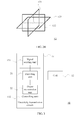
- FIG. 2A is a schematic diagram of a combination of two mutually perpendicular subcoils in Embodiment 1 of the electricity transmission sending device according to the present invention.
- the coil 12 includes two subcoils 121 and 122, where the subcoil 121 and the subcoil 122 are mutually perpendicular.
- FIG. 2B is a schematic diagram of a combination of three mutually perpendicular subcoils in Embodiment 1 of the electricity transmission sending device according to the present invention.
- the coil 12 includes three subcoils 121, 122, and 123, where each two of the subcoil 121, the subcoil 122, and the subcoil 123 are mutually perpendicular.
- FIG. 2A and FIG. 2B show combination examples only of mutually perpendicular subcoils.
- the coil in the present invention may be an orthogonal coil combined in any form, which is not specifically limited herein.
- the electricity transmission sending device 10 transmits electric energy to the electricity transmission receiving device in the optimal magnetic field direction by adjusting a direction of the magnetic field generated by the coil.
- An implementation principle of a magnetic field generated by a coil is specifically as follows: according to the Ampere's circuital law (a phenomenon of current magnetic effect), a magnetic field is generated around a coil through which a current flows, where magnetic field strength is in direct proportion to a current magnitude, a magnetic field direction is perpendicular to a current direction, and a method for determining a magnetic field direction is the right-hand rule.
- Directions of magnetic fields generated by mutually perpendicular subcoils in a coil are synthesized according to a triangle law to form a magnetic field direction of the coil.
- the electricity transmission sending device 10 adjusts an amplitude ratio and a phase difference between currents of the at least two mutually perpendicular subcoils, so as to adjust the direction of the magnetic field generated by the coil to the optimal magnetic field direction, that is, when the electricity transmission sending device 10 performs wireless electricity transmission to the electricity transmission receiving device in the optimal magnetic field direction, the power value of the electric energy actually received by the electricity transmission receiving device is maximum, which solves an inefficient electric energy transmission problem.
- FIG. 3 is a schematic structural diagram of Embodiment 2 of an electricity transmission sending device according to the present invention.
- the electricity transmission sending device provided by this embodiment is based on the device structure shown in FIG. 1 .
- the controlling unit 112 may include a directing unit 21 and a power transmission unit 22.
- the directing unit 21 is configured to adjust an amplitude ratio and a phase difference between currents of the at least two mutually perpendicular subcoils, so as to control the magnetic field direction to perform step change and determine a corresponding magnetic field direction when the power value of the actually received electric energy is maximum in the step change process as the optimal magnetic field direction.
- the power transmission unit 22 is configured to control the coil to transmit electric energy to the electricity transmission receiving device in the optimal magnetic field direction and adjust output power of the electricity transmission sending device, so that the power value of the electric energy actually received by the electricity transmission receiving device is equal to the power value of the required electric energy.
- the controlling unit 112 of the electricity transmission sending device 10 controls the magnetic field direction to perform step change and gradually finds, according to comparison of power of the electric energy actually received by the electricity transmission receiving device in the step change process, a corresponding direction when the power value of the electric energy actually received by the electricity transmission receiving device is maximum.
- the electricity transmission sending device keeps transmitting electric energy to the electricity transmission receiving device in the direction, which can reduce an electric energy loss in a transmission path and improve the electric energy transmission efficiency.
- FIG. 4 is a schematic structural diagram of Embodiment 3 of an electricity transmission sending device according to the present invention.
- the electricity transmission sending device provided by this embodiment is based on the device structure shown in FIG. 3 .
- the directing unit 21 may include a step controlling unit 31 and a sampling and comparing unit 32.
- the step controlling unit 31 is configured to adjust the amplitude ratio and the phase difference between the currents of the at least two mutually perpendicular subcoils, so as to control the magnetic field direction to step towards a same direction at a fixed angle until the magnetic field direction returns to an initial position before the stepping.
- the sampling and comparing unit 32 is configured to obtain a power value of electric energy actually received by the electricity transmission receiving device before the stepping and obtain a power value of actually received electric energy, which is obtained after each stepping; compare all the obtained power values of the actually received electric energy; and determine a magnetic field direction corresponding to a maximum power value of the actually received electric energy as the optimal magnetic field direction.
- the directing unit 21 of the controlling unit 112 of the electricity transmission sending device 10 controls the magnetic field direction to step towards the same direction at the fixed angle, repeatedly compares, in the step change process, power values of the electric energy actually received by the electricity transmission receiving device, and finally determines an optimal magnetic field direction, thereby achieving a purpose of improving the electric energy transmission efficiency.
- FIG. 5 is a schematic structural diagram of Embodiment 4 of an electricity transmission sending device according to the present invention.
- the step controlling unit 31 may further include a delayer 41, a direct current voltage-adjustable power source 42, and a high frequency inverter 43.
- the high frequency inverter 43 is configured to convert a direct current output by the direct current voltage-adjustable power source into an alternating current and then output the alternating current to the at least two mutually perpendicular subcoils.
- the delayer 41 is configured to delay a frequency driving signal, where the delayed frequency driving signal is used to generate a phase difference between the currents of the at least two mutually perpendicular subcoils, where the phase difference is used to determine a range of a two-dimensional quadrant or a three-dimensional quadrant in which a direction of the magnetic field generated by the at least two coils is located.
- the direct current voltage-adjustable power source 42 is configured to output a direct current and adjust the amplitude ratio between the currents output to the at least two mutually perpendicular subcoils, so as to adjust the direction of the magnetic field generated by the coil to perform step change within the range.
- quantities of delayers 41, direct current voltage-adjustable power sources 42, and high frequency inverters 43 included in the step controlling unit 31 and a circuit connection manner may be adjusted based on an actual requirement.
- FIG. 6 is a first schematic diagram of a partial structure of Embodiment 4 of the electricity transmission sending device according to the present invention.
- the manner in which the step controlling unit 31 and the coil are connected in FIG. 5 is related to the number of coils and the method for generating a magnetic field direction.
- the coil includes a first subcoil 45a and a second subcoil 45b that are mutually perpendicular, and a capacitor 46. Accordingly, in this embodiment, the step controlling unit 31 in the device structure shown in FIG.
- first direct current voltage-adjustable power source 42a may include a first direct current voltage-adjustable power source 42a, a second direct current voltage-adjustable power source 42b, a first high frequency inverter 43a, a second high frequency inverter 43b, the delayer 41, and a pulse width modulator (Pulse Width Modulation, PWM for short) 44.
- PWM Pulse Width Modulation
- the first direct current voltage-adjustable power source 42a and the first high frequency inverter 43a are configured to control a current of the first subcoil 45a
- the second direct current voltage-adjustable power source 42b and the second high frequency inverter 43b are configured to control a current of the second subcoil 45b
- the delayer 41 is configured to generate a delay of the current of the first subcoil 45a, so as to generate a phase difference between the currents of the two mutually perpendicular subcoils.
- the phase difference may be adjusted to 0° or 180°.
- the currents of the two subcoils are either forward or backward.
- a magnetic field direction is located in the first or third quadrant.
- a magnetic field direction is located in the second or fourth quadrant.
- a amplitude ratio between the currents may be adjusted to any ratio, for example, 1:2, 3:1, or 1:-2.
- Each ratio corresponds to a deflection angle of the magnetic field direction in the foregoing quadrant in which the magnetic field direction is located. Therefore, change in the magnetic field direction of the electricity transmission sending device can be implemented in any direction.
- FIG. 7 is a second schematic diagram of a partial structure of Embodiment 4 of the electricity transmission sending device according to the present invention.
- the manner in which the step controlling unit 31 and the coil are connected in FIG. 5 is related to the number of coils and the method for generating a magnetic field direction.
- the coil includes the first subcoil 45a and the second subcoil 45b that are mutually perpendicular, and the capacitor 46.
- the step controlling unit 31 in the device structure shown in FIG. 5 may include the direct current voltage-adjustable power source 42, the first high frequency inverter 43a, the second high frequency inverter 43b, the delayer 41, and the PWM 44.
- the first high frequency inverter 43a is configured to control a current of the first subcoil 45a
- the second high frequency inverter 43b is configured to control a current of the second subcoil 45b
- the direct current voltage-adjustable power source 42 is configured to cause an amplitude ratio between the currents of the two subcoils to be 1:1
- the delayer 41 is configured to generate a delay of the current of the first subcoil 45a, so as to generate a phase difference between the currents of the two mutually perpendicular subcoils.
- the phase difference may be adjusted within any planar angle range except 0° or 180°. According to different phase differences, durations in which the magnetic field direction stays in four two-dimensional quadrants are different.
- the magnetic field direction may periodically change in the four quadrants as time changes.
- the amplitude ratio between the currents is 1:1, which enables even distribution of the magnetic field direction in any quadrant. Therefore, change of the magnetic field direction of the electricity transmission sending device can be implemented in any direction.
- FIG. 8 is a third schematic diagram of a partial structure of Embodiment 4 of the electricity transmission sending device according to the present invention.
- the manner in which the step controlling unit 31 and the coil are connected in FIG. 5 is related to the number of coils and the method for generating a magnetic field direction.
- the coil includes the first subcoil 45a, the second subcoil 45b, and a third subcoil 45c that are mutually perpendicular, and the capacitor 46. Accordingly, in this embodiment, the step controlling unit 31 in the device structure shown in FIG.
- 5 may include the first direct current voltage-adjustable power source 42a, the second direct current voltage-adjustable power source 42b, a third direct current voltage-adjustable power source 42c, the first high frequency inverter 43a, the second high frequency inverter 43b, a third high frequency inverter 43c, the delayer 41a, a second delayer 41b, and the PWM 44.
- the first direct current voltage-adjustable power source 42a and the first high frequency inverter 43a are configured to control a current of the first subcoil 45a
- the second direct current voltage-adjustable power source 42b and the second high frequency inverter 43b are configured to control a current of the second subcoil 45b
- the third direct current voltage-adjustable power source 42c and the third high frequency inverter 43c are configured to control a current of the third subcoil 45c
- the first delayer 41a is configured to generate a delay of the current of the first subcoil 45a
- the second delayer 41b is configured to generate a delay of the current of the third subcoil 45c, so as to generate a phase difference between currents of the three mutually perpendicular subcoils.
- the phase difference may be adjusted to 0° or 180°.
- Currents of each two subcoils in the three subcoils are either forward or backward. According to a combination of a forward current and a direction, a range of a three-dimensional quadrant where a magnetic field direction is located can be determined.
- An amplitude ratio between the currents may be adjusted to any ratio, for example, 1:2:1, 3:1:1, or 1:-2:1.
- Each ratio corresponds to a deflection angle of a magnetic field direction in the foregoing quadrant in which the magnetic field direction is located. Therefore, change of the magnetic field direction of the electricity transmission sending device can be implemented in any direction.
- FIG. 9 is a fourth schematic diagram of a partial structure of Embodiment 4 of the electricity transmission sending device according to the present invention.
- the manner in which connecting the step controlling unit 31 and the coil are connected in FIG. 5 is related to the number of coils and the method for generating a magnetic field direction.
- the coil includes the first subcoil 45a, the second subcoil 45b, and the third subcoil 45c that are mutually perpendicular, and the capacitor 46. Accordingly, in this embodiment, the step controlling unit 31 in the device structure shown in FIG.
- 5 may include the direct current voltage-adjustable power source 42, the first high frequency inverter 43a, the second high frequency inverter 43b, the third high frequency inverter 43c, the first delayer 41a, the second delayer 41b, and the PWM 44.
- the first high frequency inverter 43a is configured to control a current of the first subcoil 45a
- the second high frequency inverter 43b is configured to control a current of the second subcoil 45b
- the third high frequency inverter 43c is configured to control a current of the third subcoil 45c
- the direct current voltage-adjustable power source 42 is configured to cause an amplitude ratio between the currents of the three subcoils to be 1:1:1
- the first delayer 41a is configured to generate a delay of the current of the first subcoil 45a
- the second delayer 41b is configured to generate a delay of the current of the third subcoil 45c, so as to generate a phase difference between the currents of the three mutually perpendicular subcoils.
- the phase difference between the currents of each two subcoils may be adjusted within any planar angle range except 0° or 180°. According to different phase differences, durations in which the magnetic field direction stays in eight three-dimensional quadrants are different.
- the magnetic field direction may periodically change in the eight quadrants as time changes. The amplitude ratio between the currents is 1:1:1, which enables even distribution of the magnetic field direction in any quadrant. Therefore, change of the magnetic field direction of the electricity transmission sending device can be implemented in any direction.
- FIG. 10A is a schematic diagram of same phase in Method 1 for adjusting the magnetic field direction by the electricity transmission sending device according to the present invention.
- FIG. 10B is a schematic diagram of opposite phases in Method 1 for adjusting the magnetic field direction by the electricity transmission sending device according to the present invention.
- a phase difference between currents flowing through two mutually perpendicular subcoils is set to 0° or 180°, corresponding to a same phase or opposite phases respectively. As time changes, the currents of the two subcoils always keep the same or opposite phases.
- a magnetic field strength is in direct proportion to a current magnitude and a direction is controlled by a current direction.
- FIG. 11A is a schematic diagram of magnetic field quadrants of Method 1 for adjusting the magnetic field direction by the electricity transmission sending device according to the present invention.
- FIG. 11B is a schematic diagram of an in-phase magnetic field of Method 1 for adjusting the magnetic field direction by the electricity transmission sending device according to the present invention.
- FIG. 11C is a schematic diagram of an opposite-phase magnetic field of Method 1 for adjusting the magnetic field direction by the electricity transmission sending device according to the present invention.
- an X-axis and a Y-axis that are mutually perpendicular divide a plane into four quadrants.
- FIG. 11A an X-axis and a Y-axis that are mutually perpendicular divide a plane into four quadrants.
- FIG. 11A an X-axis and a Y-axis that are mutually perpendicular divide a plane into four quadrants.
- FIG. 11A an X-axis and a Y-axis that are mutually perpendic
- a direction of a magnetic field generated by a current Ix points to a positive direction of the Y-axis; a direction of a magnetic field generated by a current Iy points to a positive direction of the X-axis; and in this case, a magnetic field direction B is in the first quadrant.
- a direction of a magnetic field generated by a current Ix points to a negative direction of the Y-axis; a direction of a magnetic field generated by a current Iy points to a positive direction of the X-axis; and in this case, a magnetic field direction B is in the fourth quadrant.
- FIG. 12A is a first schematic diagram of current amplitudes of Method 1 for adjusting the magnetic field direction by the electricity transmission sending device according to the present invention.
- FIG. 12B is a second schematic diagram of current amplitudes of Method 1 for adjusting the magnetic field direction by the electricity transmission sending device according to the present invention.
- FIG. 12C is a third schematic diagram of current amplitudes of Method 1 for adjusting the magnetic field direction by the electricity transmission sending device according to the present invention.
- peak strength values of a magnetic field B_x generated by the current Ix and a magnetic field B_y generated by the current Iy are also the same.
- a magnetic field direction is in the first quadrant, and more precisely, in a direction clockwise deviated from a direction of the magnetic field B_y by an angle of 45°.
- a peak strength ratio of the magnetic field B_x generated by the current Ix to the magnetic field B_y generated by the current Iy is also 1:2. Therefore, a magnetic field direction is in the first quadrant, and more precisely, in a direction clockwise deviated from a direction of the magnetic field B_y by an angle of 30°. As shown in FIG.
- a peak strength ratio of the magnetic field B_x generated by the current Ix to the magnetic field B_y generated by the current Iy is also 1:2. Therefore, a magnetic field direction is in the second quadrant, and more precisely, in a direction counter-clockwise deviated from a direction of the magnetic field B_y by an angle of 30°.
- Emulation software may be used to obtain magnetic field distribution in a case of different amplitude ratios between currents. The following uses several examples to specifically indicate distribution of a synthesized magnetic field.
- FIG. 12D is a first diagram of magnetic field emulation for Method 1 for adjusting the magnetic field direction by the electricity transmission sending device according to the present invention.
- FIG. 12E is a second diagram of magnetic field emulation for Method 1 for adjusting the magnetic field direction by the electricity transmission sending device according to the present invention.
- FIG. 12F is a third diagram of magnetic field emulation for Method 1 for adjusting the magnetic field direction by the electricity transmission sending device according to the present invention.
- FIG. 12D is a first diagram of magnetic field emulation for Method 1 for adjusting the magnetic field direction by the electricity transmission sending device according to the present invention.
- FIG. 12E is a second diagram of magnetic field emulation for Method 1 for adjusting the magnetic field direction by the electricity transmission sending device according to the present invention.
- FIG. 12F is a third
- FIG. 12G is a fourth diagram of magnetic field emulation for Method 1 for adjusting the magnetic field direction by the electricity transmission sending device according to the present invention.
- an amplitude ratio of the current Ix to the current Iy is 1:1, indicating that the currents are in a same phase.
- an amplitude ratio of the current Ix to the current Iy is 1:-1, indicating that the currents are in opposed phases.
- an amplitude ratio of the current Ix to the current Iy is 3:1, indicating that the currents are in a same phase.
- an amplitude ratio of the current Ix to the current Iy is 3:-1, indicating that the currents are in opposed phases.
- a magnetic field direction can be controlled to be in the first or third quadrant by adjusting currents flowing through two mutually perpendicular subcoils to be in a same phase, or a magnetic field direction can be controlled to be in the second or fourth quadrant by adjusting currents flowing through two mutually perpendicular subcoils to be in opposite phases; and then the magnetic field direction can be controlled in a more precise direction by adjusting a ratio between or values of amplitudes of the currents flowing through the two mutually perpendicular subcoils.
- FIG. 10A to FIG. 12C are schematic diagrams of Method 1 for adjusting the magnetic field direction by the electricity transmission sending device.
- a magnetic field direction can be precisely controlled to fall within a planar angle range and even in any direction within three-dimensional space.
- a strongest electromagnetic wave is radiated by the electricity transmission sending device, and a largest amount of electric energy is transmitted accordingly. Therefore, the electric energy transmission efficiency is greatly improved by only adjusting the direction to point exactly to an electricity transmission receiving device.
- power can be supplied to the multiple receiving devices only by changing, in real time, a ratio between or values of amplitudes of currents flowing through subcoils, so that a magnetic field direction is continuously scanned in the quadrant.
- a magnetic field direction is firstly controlled within a planar angle range of the X-axis and the Y-axis and then a final magnetic field direction is controlled by further using the Z-axis, that is, the magnetic field direction is controlled within two planar angle ranges in two steps.
- FIG. 13A is a first schematic phase diagram of Method 2 for adjusting the magnetic field direction by the electricity transmission sending device according to the present invention.
- FIG. 13B is a second schematic phase diagram of Method 2 for adjusting the magnetic field direction by the electricity transmission sending device according to the present invention.
- FIG. 13C is a third schematic phase diagram of Method 2 for adjusting the magnetic field direction by the electricity transmission sending device according to the present invention.
- FIG. 13D is a fourth schematic phase diagram of Method 2 for adjusting the magnetic field direction by the electricity transmission sending device according to the present invention.
- FIG. 13E is a fifth schematic phase diagram of Method 2 for adjusting the magnetic field direction by the electricity transmission sending device according to the present invention.
- FIG. 13A is a first schematic phase diagram of Method 2 for adjusting the magnetic field direction by the electricity transmission sending device according to the present invention.
- FIG. 13B is a second schematic phase diagram of Method 2 for adjusting the magnetic field direction by the electricity transmission sending device according to the present invention.
- FIG. 13C is a third schematic
- FIG. 13F is a sixth schematic phase diagram of Method 2 for adjusting the magnetic field direction by the electricity transmission sending device according to the present invention.
- phases and amplitudes of two currents continuously vary as time changes.
- a magnetic field direction keeps changing accordingly.
- time lengths of a to b and c to d are large, that is, the currents are in a same phase for a long time, and therefore, the magnetic field direction is mainly centralized in the first and third quadrants and there is a maximum value.
- phase difference between the currents is equal to 90° or 270°
- time lengths of a to b, b to c, and c to d are the same, that is, a time in which the currents are in a same phase is equal to a time in which the currents are in opposite phases, and therefore, time lengths of the magnetic field direction in four quadrants are equal and maximum values are equal.
- the phase difference between the currents is greater than 90° and less than 270°, a time in which the currents are in opposite phases is long, and therefore, the magnetic field direction is mainly centralized in the second and fourth quadrants and there is a maximum value.
- a magnetic field direction can be controlled to be in an expected quadrant for a longer time by controlling a phase difference between currents flowing through two mutually perpendicular subcoils to be within any planar angle range except 0° or 180°, and therefore an electricity transmission receiving device can receive higher power as long as the electricity transmission receiving device is located in the quadrant.
- the phase difference between the currents flowing through the two mutually perpendicular subcoils can be controlled to be between 0° and 90°. In this case, change in phases of currents is shown in FIG.
- FIG. 13A where the magnetic field direction is located in the first and third quadrants for most of the time, an electric energy transmission requirement can be met. If electricity transmission receiving devices are distributed in four quadrants, it is only necessary to control the phase difference between the currents flowing through the two mutually perpendicular subcoils to be 90° or 270°. In this case, change in phases of currents is shown in FIG. 13B or FIG. 13E , where time lengths of the magnetic field direction in the four quadrants are equal, that is, electric energy can be evenly transmitted to the electricity transmission receiving devices in the quadrants.
- a magnetic field direction is first controlled within a planar angle range of the X-axis and the Y-axis and then a final magnetic field direction is controlled by using the Z-axis, that is, the magnetic field direction is controlled within two planar angle ranges in two steps.
- Emulation software may be used to obtain magnetic field distribution in a case of different amplitude ratios between currents. The following uses several examples to specifically indicate distribution of a synthesized magnetic field.
- FIG. 13G is a first diagram of magnetic field emulation for Method 2 for adjusting the magnetic field direction by the electricity transmission sending device according to the present invention.
- FIG. 13H is a second diagram of magnetic field emulation for Method 2 for adjusting the magnetic field direction by the electricity transmission sending device according to the present invention.
- FIG. 13I is a third diagram of magnetic field emulation for Method 2 for adjusting the magnetic field direction by the electricity transmission sending device according to the present invention.
- FIG. 13G is a first diagram of magnetic field emulation for Method 2 for adjusting the magnetic field direction by the electricity transmission sending device according to the present invention.
- FIG. 13H is a second diagram of magnetic field emulation for Method 2 for adjusting the magnetic field direction by the electricity transmission sending device according to the present invention.
- FIG. 13I is a third
- FIG. 13J is a fourth diagram of magnetic field emulation for Method 2 for adjusting the magnetic field direction by the electricity transmission sending device according to the present invention.
- a phase difference between the current Ix and the current Iy is 45°, and time is 0.001 seconds.
- a phase difference between the current Ix and the current Iy is 45°, and time is 0.004 seconds.
- a phase difference between the current Ix and the current Iy is 90°, and time is 0.001 seconds.
- FIG. 13J a phase difference between the current Ix and the current Iy is 90°, and time is 0.009 seconds.
- the electricity transmission sending device 10 can control a magnetic field direction to fall within a range of a planar angle of 360° and even in any direction of a three-dimensional azimuth by adjusting the amplitude ratio and the phase difference between currents of mutually perpendicular subcoils. Further, as long as the magnetic field direction is adjusted to an optimal magnetic field direction, the electricity transmission receiving device can obtain maximum electric energy received power in this direction, thereby improving the electric energy transmission efficiency.
- FIG. 14A is a first schematic structural diagram of a subcoil in Embodiment 1 of the electricity transmission sending device according to the present invention.
- FIG. 14B is a second schematic structural diagram of a subcoil in Embodiment 1 of the electricity transmission sending device according to the present invention.
- FIG. 14A and FIG. 14B respectively show two schematic structural diagrams of each subcoil of the at least two mutually perpendicular subcoils.
- the subcoil is a transmit subcoil 52 that is connected to a transmission circuit 51, and a capacitor 53 is disposed on a connection line.
- the transmit subcoil 52 is a multi-turn coil and current intensity is in direct proportion to the number of turns of the coil.
- the subcoil may include two parts: an excitation subcoil 63 and a transmit subcoil 62.
- the excitation subcoil 63 is connected to a transmission circuit 61 and the transmit subcoil 62 corresponds to the excitation subcoil 63.
- a capacitor 64 is included in the transmit subcoil 62. Electric energy is transferred between the transmit subcoil 62 and the excitation subcoil 63 by means of electromagnetic induction.
- the transmit subcoil 62 is a multi-turn coil and the current intensity is in direct proportion to the number of turns of the coil. A more intense current leads to generation of a stronger magnetic field.
- the coil structure shown in FIG. 14B is to protect a transmission circuit against an impact of an intense current.
- mutually perpendicular subcoils may be coils in any form and the number of coil turns may also be any number, which is not specifically limited herein.
- FIG. 15 is a flowchart of Embodiment 1 of an electricity transmission sending method according to the present invention. As shown in FIG. 15 , the method provided by this embodiment may include:
- Step 101 Receive a required power signal and an actually received power signal that are sent by an electricity transmission receiving device, where the required power signal includes a power value of electric energy required by the electricity transmission receiving device and the actually received power signal includes a power value of electric energy actually received by the electricity transmission receiving device.
- This embodiment is executed by an electricity transmission sending device.
- a communications unit of the electricity transmission sending device communicates with a communications unit of the electricity transmission receiving device to receive the required power signal and the actually received power signal that are sent by the electricity transmission receiving device.
- the required power signal is the power value of the electric energy required by the electricity transmission receiving device and the actually received power signal is the power value of the electric energy actually received by the electricity transmission receiving device.
- the electricity transmission sending device can learn a requirement of the electricity transmission receiving device and an electric energy transmission status in real time.
- Step 102 Adjust a magnetic field direction in which wireless electricity transmission to the electricity transmission receiving device is performed, so as to transmit electric energy to the electricity transmission receiving device in an optimal magnetic field direction, where the optimal magnetic field direction is a corresponding magnetic field direction when a power value of electric energy actually received by the electricity transmission receiving device is maximum in a case of specific output power of the coil.
- the electricity transmission sending device adjusts the magnetic field direction in which wireless electricity transmission to the electricity transmission receiving device is performed, with a purpose of transmitting electric energy to the electricity transmission receiving device in the optimal magnetic field direction.
- the electricity transmission sending device transmits electric energy to the electricity transmission receiving device in the optimal magnetic field direction, power of the electric energy received by the electricity transmission receiving device is maximum, which is exactly an expected effect in wireless electricity transmission.
- Step 103 Adjust output power so that the power value of electric energy actually received by the electricity transmission receiving device in the optimal magnetic field direction is equal to the power value of required electric energy.
- the electricity transmission sending device can transmit electric energy to the electricity transmission receiving device in this direction according to a magnetic field resonance principle.
- the electricity transmission sending device can adjust output power according to the power value of the electric energy required by the electricity transmission receiving device in the required power signal, so that the power value of the electric energy actually received by the electricity transmission receiving device in the optimal magnetic field direction is equal to the power value of the required electric energy.
- the magnetic field direction in which wireless electricity transmission to the electricity transmission receiving device is performed is adjusted according to the required power signal and the actually received power signal of the electricity transmission receiving device, so as to adjust the magnetic field direction to the optimal magnetic field direction, that is, the power value of the electric energy actually received by the electricity transmission receiving device is maximum when the electricity transmission sending device performs wireless electricity transmission to the electricity transmission receiving device in the optimal magnetic field direction, which solves an inefficient electric energy transmission problem.
- an electric energy requirement of the electricity transmission receiving device is met by adjusting the output power.
- FIG. 16 is a flowchart of Embodiment 2 of an electricity transmission sending method according to the present invention. As shown in FIG. 16 , the method provided by this embodiment may include:
- Step 201 Receive a required power signal and an actually received power signal that are sent by an electricity transmission receiving device, where the required power signal includes a power value of electric energy required by the electricity transmission receiving device and the actually received power signal includes a power value of electric energy actually received by the electricity transmission receiving device.
- a process of receiving the required power signal and the actually received power signal that are sent by the electricity transmission receiving device is similar to step 101 in the foregoing method embodiment, and details are not described herein again.
- Step 202 Adjust, in a case of specific output power of a coil, a magnetic field direction by adjusting an amplitude ratio and a phase difference between currents of two or three mutually perpendicular subcoils, so as to cause the magnetic field direction to perform step change at a fixed angle.
- the electricity transmission sending device determines one power value as the output power.
- the power value may be the power value of the electric energy required by the electricity transmission receiving device, or may be another power value, which is not specifically limited herein.
- the electricity transmission sending device adjusts the magnetic field direction by adjusting the amplitude ratio and phase difference between currents of the two or three mutually perpendicular subcoils. A specific implementation method is shown in FIG. 11A to FIG. 14J , and details are not described herein again. According to the foregoing description, the electricity transmission sending device can precisely perform step change on the magnetic field direction at a fixed angle.
- Step 203 Determine, according to power values of actually received electric energy, which are received in the step change process of the magnetic field direction, a corresponding magnetic field direction when the power value of the electric energy actually received by the electricity transmission receiving device is maximum as an optimal magnetic field direction.
- the electricity transmission sending device while performing step change on the magnetic field direction, receives the power value of the actually received electric energy that is sent by the electricity transmission receiving device, and acquires a maximum power value of the electric energy actually received by the electricity transmission receiving device in the step change process by means of iterative comparison.
- a magnetic field direction corresponding to the maximum power value is the optimal magnetic field direction.
- Step 204 Transmit electric energy to the electricity transmission receiving device in the optimal magnetic field direction.
- the electricity transmission sending device performs wireless electricity transmission to the electricity transmission receiving device in the optimal magnetic field direction; and in this case, power of the electric energy actually received by the electricity transmission receiving device is maximum and least electric energy is lost in a transmission path, which is exactly an expected effect in wireless electricity transmission.
- Step 205 Adjust output power so that the power value of electric energy actually received by the electricity transmission receiving device in the optimal magnetic field direction is equal to the power value of required electric energy.
- a process of adjusting output power so that the power value of the electric energy actually received by the electricity transmission receiving device in the optimal magnetic field direction is equal to the power value of required electric energy is similar to step 103 in the foregoing method embodiment, and details are not described herein again.
- the magnetic field direction in which wireless electricity transmission to the electricity transmission receiving device is performed is adjusted according to the required power signal and the actually received power signal of the electricity transmission receiving device, so as to adjust the magnetic field direction to the optimal magnetic field direction by using an iterative comparison method, that is, the power value of the electric energy actually received by the electricity transmission receiving device is maximum when the electricity transmission sending device performs wireless electricity transmission to the electricity transmission receiving device in the optimal magnetic field direction, which solves an inefficient electric energy transmission problem.
- an electric energy requirement of the electricity transmission receiving device is met by adjusting the output power.
- a specific implementation method for the adjusting, in a case of specific output power of the coil, the magnetic field direction by adjusting the amplitude ratio and the phase difference between currents of two or three mutually perpendicular subcoils, so as to cause the magnetic field direction to perform step change at a fixed angle in step 202 may include: adjusting a range of a two-dimensional quadrant or a three-dimensional quadrant in which the magnetic field direction is located by adjusting the phase difference; and adjusting a deflection angle of the magnetic field direction within the range by adjusting the amplitude ratio between the currents, so as to cause the magnetic field direction to perform step change at the fixed angle.
- the electricity transmission sending device adjusts the magnetic field direction by adjusting the amplitude ratio and the phase difference between the currents of the two or three mutually perpendicular subcoils.
- the phase difference between the currents may determine the range of the magnetic field direction in the two-dimensional quadrant or the three-dimensional quadrant, for example, in the two-dimensional quadrant, a phase difference of 0° indicates a same phase and that a magnetic field direction is located in the first and third quadrants; and a phase difference of 180° indicates opposite phases and that a magnetic field direction is located in the second and fourth quadrants.
- the amplitude ratio between the currents can determine a deflection angle of the magnetic field direction in a quadrant in which the magnetic field direction is located, for example, when an amplitude ratio between the currents is 1:2, it indicates that a deflection angle of a magnetic field direction is 30°. Therefore, the magnetic field direction can be precisely adjusted.
- a detailed implementation principle and method are shown in FIG. 9A to FIG. 12J , and details are not described herein again.
- FIG. 17 is a flowchart of Embodiment 3 of an electricity transmission sending method according to the present invention.
- a specific implementation method for the determining, according to power values of actually received electric energy, which are received in the step change process of the magnetic field direction, a corresponding magnetic field direction when the power value of the electric energy actually received by the electricity transmission receiving device is maximum as the optimal magnetic field direction in step 203 in the method process shown in FIG. 16 may include:
- Step 301 Obtain a first power value of electric energy actually received by the electricity transmission receiving device in an initial position of a current magnetic field direction.
- the electricity transmission sending device can adjust an initial position of the magnetic field direction to any direction because the electricity transmission sending device does not learn the position of the electricity transmission receiving device at an initial stage. Therefore, at this stage, any direction may be used as the initial magnetic field direction for performing wireless electricity transmission; and in this case, the actually received power signal that is received by the electricity transmission sending device and sent by the electricity transmission receiving device includes the first power value of the actually received electric energy.
- Step 302 Control the magnetic field direction to step at a fixed angle and obtain a second power value of actually received electric energy in an after-stepping magnetic field direction.
- the electricity transmission sending device adjusts the magnetic field direction to step at the fixed angle and obtains the second power value of the actually received electric energy, where the second power value is included in the actually received power signal that is sent by the electricity transmission receiving device in the after-stepping magnetic field direction.
- Step 303 Compare the first power value of the actually received electric energy and the second power value of the actually received electric energy, and use a larger value between the two as a maximum power value of the actually received electric energy.
- Step 304 Control the magnetic field direction to step at the fixed angle and obtain a third power value of actually received electric energy in an after-stepping magnetic field direction.
- the electricity transmission sending device adjusts the magnetic field direction to step further at the fixed angle and obtains the third power value of the actually received electric energy, where the third power value is included in the actually received power signal that is sent by the electricity transmission receiving device in the after-further-stepping magnetic field direction.
- Step 305 Compare the maximum power value of the actually received electric energy and the third power value of the actually received electric energy, and use a larger value between the two as a maximum power value of the actually received electric energy.
- a larger value in the power values of the electric energy actually received by the electricity transmission receiving device in the first two steppings is compared with the third power value of the actually received electric energy, to acquire a maximum value of the actually received energy among the three.
- Step 306 Repeat the foregoing steps 301 to 305 until the magnetic field direction returns to the initial position, and use a magnetic field direction corresponding to the maximum power value of the actually received electric energy, which is obtained in the stepping process, as the optimal magnetic field direction.
- the maximum power value of the actually received electric energy is acquired by iteratively comparing the power values of the electric energy actually received by the electricity transmission receiving device in the stepping process, and the magnetic field direction corresponding to the maximum power value is used as the optimal magnetic field direction, so that the power value of the electric energy actually received by the electricity transmission receiving device is maximum when the electricity transmission sending device performs wireless electricity transmission to the electricity transmission receiving device in the optimal magnetic field direction, which solves an inefficient electric energy transmission problem.
- an electric energy requirement of the electricity transmission receiving device is met by adjusting the output power.
- FIG. 18 is a schematic structural diagram of Embodiment 1 of an electricity transmission sending apparatus according to the present invention.
- the apparatus provided by this embodiment may include: a communications module 11, an optimal electricity transmission module 12, and an electric energy transmission module 13.
- the communications module 11 is configured to receive a required power signal and an actually received power signal that are sent by an electricity transmission receiving device, where the required power signal includes a power value of electric energy required by the electricity transmission receiving device and the actually received power signal includes a power value of electric energy actually received by the electricity transmission receiving device.
- the optimal electricity transmission module 12 is configured to adjust a magnetic field direction in which wireless electricity transmission to the electricity transmission receiving device is performed, so as to transmit electric energy to the electricity transmission receiving device in an optimal magnetic field direction, where the optimal magnetic field direction is a corresponding magnetic field direction when a power value of electric energy actually received by the electricity transmission receiving device is maximum in a case of specific output power of the coil.
- the electric energy transmission module 13 is configured to adjust output power of the coil so that the power value of electric energy actually received by the electricity transmission receiving device in the optimal magnetic field direction is equal to the power value of required electric energy.
- the apparatus provided by this embodiment can be configured to execute the technical solution of the method embodiment shown in FIG. 15 . Its implementation principle and technical effect are similar, and details are not described herein again.
- FIG. 19 is a schematic structural diagram of Embodiment 2 of an electricity transmission sending apparatus according to the present invention.
- the apparatus provided by this embodiment is based on the apparatus structure shown in FIG. 18 .
- the optimal electricity transmission module 12 may include: an adjusting unit 121, a direction determining unit 122, and an electricity transmission unit 123.
- the adjusting unit 121 is configured to adjust, in a case of specific output power of the coil, the magnetic field direction by adjusting an amplitude ratio and a phase difference between currents of the two or three mutually perpendicular subcoils, so as to cause the magnetic field direction to perform step change at a fixed angle.
- the direction determining unit 122 is configured to determine, according to power values of actually received electric energy, which are received in the step change process of the magnetic field direction, a corresponding magnetic field direction when the power value of the electric energy actually received by the electricity transmission receiving device is maximum as the optimal magnetic field direction.
- the electricity transmission unit 123 is configured to transmit electric energy to the electricity transmission receiving device in the optimal magnetic field direction and adjust output power of the coil, so that the power value of electric energy actually received by the electricity transmission receiving device is equal to the power value of required electric energy.
- the adjusting unit 121 may further be specifically configured to: adjust a range of a two-dimensional quadrant or a three-dimensional quadrant in which the magnetic field direction is located by adjusting the phase difference; and adjust a deflection angle of the magnetic field direction within the range by adjusting the amplitude ratio between the currents, so as to cause the magnetic field direction to perform step change at the fixed angle.
- the apparatus provided by this embodiment can be configured to execute the technical solution of the method embodiment shown in FIG. 15 or FIG. 16 . Its implementation principle and technical effect are similar, and details are not described herein again.
- FIG. 20 is a schematic structural diagram of Embodiment 3 of an electricity transmission sending apparatus according to the present invention.
- the apparatus provided by this embodiment is based on the apparatus structure shown in FIG. 19 .
- the direction determining unit 122 may include: a cyclic stepping unit 21 and a comparing and determining unit 22.
- the cyclic stepping unit 21 is configured to control the magnetic field direction to step towards a same direction at the fixed angle until the magnetic field direction returns to an initial position.
- the comparing and determining unit 22 is configured to obtain a power value of electric energy actually received by the electricity transmission receiving device before the stepping and obtain a power value of actually received electric energy, which is obtained after each stepping; compare all the obtained power values of the actually received electric energy; and determine a magnetic field direction corresponding to a maximum power value of the actually received electric energy as the optimal magnetic field direction.
- the apparatus provided by this embodiment can be configured to execute the technical solution of the method embodiment shown in any one of FIG. 15 to FIG. 17 . Its implementation principle and technical effect are similar, and details are not described herein again.
- FIG. 21 is a schematic structural diagram of an electric energy transmission system according to an embodiment of the present invention.
- the system provided by this embodiment may include: an electricity transmission sending device 11 and an electricity transmission receiving device 12.
- the electricity transmission sending device 11 may use the structure of any electricity transmission sending device embodiment shown in the foregoing FIG. 1 to FIG. 9 , FIG. 14A, and FIG. 14B .
- the electricity transmission sending device 11 performs wireless electricity transmission to the electricity transmission receiving device 12.
- the electricity transmission receiving device 12 may include an electricity transmission receiving circuit 21 that is configured to receive wireless electricity transmission and a receiving coil 22.
- the receiving coil 22 includes a signal sending unit 221, where the signal sending unit 221 is configured to send a required power signal and an actually received power signal to the electricity transmission sending device 11.
- the electricity transmission receiving circuit 21 is configured to receive electric energy that the electricity transmission sending device 11 transmits by means of wireless electricity transmission.
- the electricity transmission sending device performs wireless electricity transmission to the electricity transmission receiving device, which implements "obtaining electricity across space", minimizes an electric energy loss in a transmission path, and improves the electric energy transmission efficiency.
- the program may be stored in a computer readable storage medium.
- the foregoing storage medium includes: any medium that can store program code, such as a ROM, a RAM, a magnetic disk, or an optical disc.
Landscapes
- Engineering & Computer Science (AREA)
- Computer Networks & Wireless Communication (AREA)
- Power Engineering (AREA)
- Signal Processing (AREA)
- Charge And Discharge Circuits For Batteries Or The Like (AREA)
- Near-Field Transmission Systems (AREA)
Abstract
Description
- Embodiments of the present invention relate to electricity transmission technologies, and in particular, to an electricity transmission sending method and device, and a system.
- The origin of the concept of wireless electricity transmission can be traced back to 1889. With his lofty ideal of global wireless power supply, Nikola Tesla, a physicist and electrical engineer, started so that preparations for building Ed den Cliff Kobita and initiated a great challenge to a conducting wire that restricts electric energy. Since Nikola Tesla ignited the dream of human beings for wireless electricity transmission, people's research on wireless electric energy transmission has been constantly moving forward. In the past century, science and technology as well as civilization developed rapidly, the electronic communications industry advanced rapidly, people made a great breakthrough in research on wireless electric energy transmission technologies, and a phantom of "obtaining electricity across space" also came true.
- In the prior art, electric energy is mainly transmitted from an electricity transmission sending device to an electricity transmission receiving device by means of electromagnetic wave radiation. Specifically speaking, an electricity transmission sending device can convert an electrical signal into an electromagnetic wave signal and send the electromagnetic wave signal to an electricity transmission receiving device through space; and the electricity transmission receiving device can re-convert the electromagnetic wave signal into an electrical signal, so as to obtain electric energy.
- However, the prior art allows sending electromagnetic wave radiation to an electricity transmission receiving device only in several fixed directions. In reality, an electricity transmission receiving device may not be exactly located in the several fixed directions. As a result, power of electric energy actually received by the electricity transmission receiving device is lower than power of electric energy actually received when a direction points exactly to the receiving device, causing an inefficient electric energy transmission problem.
- Embodiments of the present invention provide an electricity transmission sending method and device, and a system, so as to solve an inefficient electric energy transmission problem that is because, when an electricity transmission sending device performs wireless electricity transmission to an electricity transmission receiving device, power of electric energy actually received by the electricity transmission receiving device is lower than power of electric energy actually received when a direction points exactly to the receiving device.
- According to a first aspect, an embodiment of the present invention provides an electricity transmission sending device, where the electricity transmission sending device is configured to perform wireless electricity transmission to an electricity transmission receiving device and the electricity transmission sending device includes an transmission circuit and a coil, where the transmission circuit includes a signal sending unit and a controlling unit, and the coil includes at least two mutually perpendicular subcoils, where:
- the signal sending unit is configured to receive a required power signal and an actually received power signal that are sent by the electricity transmission receiving device, where the required power signal includes a power value of electric energy required by the electricity transmission receiving device and the actually received power signal includes a power value of electric energy actually received by the electricity transmission receiving device;
- the controlling unit is configured to adjust a magnetic field direction in which wireless electricity transmission to the electricity transmission receiving device is performed, control the coil to transmit electric energy to the electricity transmission receiving device in an optimal magnetic field direction, and adjust output power of the coil, so that the power value of electric energy actually received by the electricity transmission receiving device is equal to the power value of required electric energy, where the optimal magnetic field direction refers to a corresponding magnetic field direction when a power value of electric energy actually received by the electricity transmission receiving device is maximum in a case of specific output power of the coil; and
- the coil is configured to generate a magnetic field and transmit, in the optimal magnetic field direction, electric energy to the electricity transmission receiving device.
- With reference to the first aspect, in a first possible implementation manner of the first aspect, the controlling unit specifically includes:
- a directing unit, configured to adjust an amplitude ratio and a phase difference between currents of the at least two mutually perpendicular subcoils, so as to control the magnetic field direction to perform step change and determine a corresponding magnetic field direction when the power value of the actually received electric energy is maximum in the step change process as the optimal magnetic field direction; and
- a power transmission unit, configured to control the coil to transmit electric energy to the electricity transmission receiving device in the optimal magnetic field direction and adjust output power of the electricity transmission sending device, so that the power value of the electric energy actually received by the electricity transmission receiving device is equal to the power value of the required electric energy.
- With reference to the first possible implementation manner of the first aspect, in a second possible implementation manner of the first aspect, the directing unit includes:
- a step controlling unit, configured to adjust the amplitude ratio and the phase difference between the currents of the at least two mutually perpendicular subcoils, so as to control the magnetic field direction to step towards a same direction at a fixed angle until the magnetic field direction returns to an initial position before the stepping; and
- a sampling and comparing unit, configured to obtain a power value of electric energy actually received by the electricity transmission receiving device before the stepping and obtain a power value of actually received electric energy, which is obtained after each stepping; compare all the obtained power values of the actually received electric energy; and determine a magnetic field direction corresponding to a maximum power value of the actually received electric energy as the optimal magnetic field direction.
- With reference to the second possible implementation manner of the first aspect, in a third possible implementation manner of the first aspect, the step controlling unit includes a delayer, a direct current voltage-adjustable power source, and a high frequency inverter, where:
- the high frequency inverter is configured to convert a direct current output by the direct current voltage-adjustable power source into an alternating current and then output the alternating current to the at least two mutually perpendicular subcoils;
- the delayer is configured to delay a frequency driving signal, where the delayed frequency driving signal is used to generate a phase difference between the currents of the at least two mutually perpendicular subcoils, where the phase difference is used to determine a range of a two-dimensional quadrant or three-dimensional quadrant in which a direction of the magnetic field generated by the at least two coils is located; and
- the direct current voltage-adjustable power source is configured to output a direct current and adjust the amplitude ratio between the currents output to the at least two mutually perpendicular subcoils, so as to adjust the direction of the magnetic field generated by the coil to perform step change within the range.
- According to a second aspect, an embodiment of the present invention provides an electric energy transmission system, including an electricity transmission sending device and an electricity transmission receiving device, where the electricity transmission sending device is the electricity transmission sending device according to the first aspect or any one of the first to third possible implementation manners of the first aspect and the electricity transmission sending device performs wireless electricity transmission to the electricity transmission receiving device; and
the electricity transmission receiving device includes an electricity transmission receiving circuit that is configured to receive wireless electricity transmission and a receiving coil, where the receiving coil includes a signal sending unit, where the signal sending unit is configured to send a required power signal and an actually received power signal to the electricity transmission sending device; and the electricity transmission receiving circuit is configured to receive electric energy that the electricity transmission sending device transmits by means of wireless electricity transmission. - According to a third aspect, an embodiment of the present invention provides an electricity transmission sending method, including:
- receiving a required power signal and an actually received power signal that are sent by an electricity transmission receiving device, where the required power signal includes a power value of electric energy required by the electricity transmission receiving device and the actually received power signal includes a power value of electric energy actually received by the electricity transmission receiving device;
- adjusting a magnetic field direction in which wireless electricity transmission to the electricity transmission receiving device is performed, so as to transmit electric energy to the electricity transmission receiving device in an optimal magnetic field direction, where the optimal magnetic field direction is a corresponding magnetic field direction when a power value of electric energy actually received by the electricity transmission receiving device is maximum in a case of specific output power of the coil; and
- adjusting output power so that the power value of electric energy actually received by the electricity transmission receiving device in the optimal magnetic field direction is equal to the power value of required electric energy.
- With reference to the third aspect, in a first possible implementation manner of the third aspect, the adjusting a magnetic field direction in which wireless electricity transmission to the electricity transmission receiving device is performed, so as to transmit electric energy to the electricity transmission receiving device in an optimal magnetic field direction includes:
- adjusting, in a case of specific output power of the coil, the magnetic field direction by adjusting an amplitude ratio and a phase difference between currents of two or three mutually perpendicular subcoils, so as to cause the magnetic field direction to perform step change at a fixed angle;
- determining, according to power values of actually received electric energy, which are received in the step change process of the magnetic field direction, a corresponding magnetic field direction when the power value of the electric energy actually received by the electricity transmission receiving device is maximum as the optimal magnetic field direction; and
- transmitting electric energy to the electricity transmission receiving device in the optimal magnetic field direction.
- With reference to the first possible implementation manner of the third aspect, in a second possible implementation manner of the third aspect, the determining, according to power values of actually received electric energy, which are received in the step change process of the magnetic field direction, a corresponding magnetic field direction when the power value of the electric energy actually received by the electricity transmission receiving device is maximum as the optimal magnetic field direction, includes:
- step 1: obtaining a first power value of electric energy actually received by the electricity transmission receiving device in an initial position of a current magnetic field direction;
- step 2: controlling the magnetic field direction to step at the fixed angle and obtaining a second power value of actually received electric energy in an after-stepping magnetic field direction;
- step 3: comparing the first power value of the actually received electric energy and the second power value of the actually received electric energy, and using a larger value between the two as a maximum power value of the actually received electric energy;
- step 4: controlling the magnetic field direction to step at the fixed angle and obtaining a third power value of actually received electric energy in an after-stepping magnetic field direction;
- step 5: comparing the maximum power value of the actually received electric energy and the third power value of the actually received electric energy, and using a larger value between the two as a maximum power value of the actually received electric energy; and
- step 6: repeating the foregoing steps 1 to 5 until the magnetic field direction returns to the initial position, and using a magnetic field direction corresponding to the maximum power value of the actually received electric energy, which is obtained in the stepping process, as the optimal magnetic field direction.
- With reference to the first or second possible implementation manner of the third aspect, in a third possible implementation manner of the third aspect, the adjusting, in a case of specific output power of the coil, the magnetic field direction by adjusting an amplitude ratio and a phase difference between currents of two or three mutually perpendicular subcoils, so as to cause the magnetic field direction to perform step change at a fixed angle, includes:
- adjusting a range of a two-dimensional quadrant or a three-dimensional quadrant in which the magnetic field direction is located by adjusting the phase difference; and
- adjusting a deflection angle of the magnetic field direction within the range by adjusting the amplitude ratio between the currents, so as to cause the magnetic field direction to perform step change at the fixed angle.
- According to a fourth aspect, an embodiment of the present invention provides an electricity transmission sending apparatus, including:
- a communications module, configured to receive a required power signal and an actually received power signal that are sent by an electricity transmission receiving device, where the required power signal includes a power value of electric energy required by the electricity transmission receiving device and the actually received power signal includes a power value of electric energy actually received by the electricity transmission receiving device;
- an optimal electricity transmission module, configured to adjust a magnetic field direction in which wireless electricity transmission to the electricity transmission receiving device is performed, so as to transmit electric energy to the electricity transmission receiving device in an optimal magnetic field direction, where the optimal magnetic field direction is a corresponding magnetic field direction when a power value of electric energy actually received by the electricity transmission receiving device is maximum in a case of specific output power of the coil; and
- an electric energy transmission module, configured to adjust output power of the coil so that the power value of electric energy actually received by the electricity transmission receiving device in the optimal magnetic field direction is equal to the power value of required electric energy.
- With reference to the fourth aspect, in a first possible implementation manner of the fourth aspect, the optimal electricity transmission module includes:
- an adjusting unit, configured to adjust, in a case of specific output power of the coil, the magnetic field direction by adjusting an amplitude ratio and a phase difference between currents of two or three mutually perpendicular subcoils, so as to cause the magnetic field direction to perform step change at a fixed angle;
- a direction determining unit, configured to determine, according to power values of actually received electric energy, which are received in the step change process of the magnetic field direction, a corresponding magnetic field direction when the power value of the electric energy actually received by the electricity transmission receiving device is maximum as the optimal magnetic field direction; and
- an electricity transmission unit, configured to transmit electric energy to the electricity transmission receiving device in the optimal magnetic field direction and adjust output power of the coil, so that the power value of electric energy actually received by the electricity transmission receiving device is equal to the power value of required electric energy.
- With reference to the first possible implementation manner of the fourth aspect, in a second possible implementation manner of the fourth aspect, the direction determining unit includes:
- a cyclic stepping unit, configured to control the magnetic field direction to step towards a same direction at the fixed angle until the magnetic field direction returns to an initial position; and
- a comparing and determining unit, configured to obtain a power value of electric energy actually received by the electricity transmission receiving device before the stepping and obtain a power value of actually received electric energy, which is obtained after each stepping; compare all the obtained power values of the actually received electric energy; and determine a magnetic field direction corresponding to a maximum power value of the actually received electric energy as the optimal magnetic field direction.
- With reference to the first or second possible implementation manner of the fourth aspect, in a third possible implementation manner of the fourth aspect, the adjusting unit is specifically configured to:
- adjust a range of a two-dimensional quadrant or a three-dimensional quadrant in which the magnetic field direction is located by adjusting the phase difference; and
- adjust a deflection angle of the magnetic field direction within the range by adjusting the amplitude ratio between the currents, so as to cause the magnetic field direction to perform step change at the fixed angle.
- According to the electricity transmission sending method and device, and the system provided by the embodiments of the present invention, the amplitude ratio and the phase difference between the currents of the at least two mutually perpendicular subcoils are adjusted, so as to adjust the magnetic field direction generated by the coil to the optimal magnetic field direction, that is, when the electricity transmission sending device performs wireless electricity transmission to the electricity transmission receiving device in the optimal magnetic field direction, the power value of the electric energy actually received by the electricity transmission receiving device is maximum, which solves an inefficient electric energy transmission problem.
- To describe the technical solutions in the embodiments of the present invention or in the prior art more clearly, the following briefly introduces the accompanying drawings required for describing the embodiments or the prior art. Apparently, the accompanying drawings in the following description show some embodiments of the present invention, and a person of ordinary skill in the art may still derive other drawings from these accompanying drawings without creative efforts.
-
FIG. 1 is a schematic structural diagram of Embodiment 1 of an electricity transmission sending device according to the present invention; -
FIG. 2A is a schematic diagram of a combination of two mutually perpendicular subcoils in Embodiment 1 of the electricity transmission sending device according to the present invention; -
FIG. 2B is a schematic diagram of a combination of three mutually perpendicular subcoils in Embodiment 1 of the electricity transmission sending device according to the present invention; -
FIG. 3 is a schematic structural diagram ofEmbodiment 2 of an electricity transmission sending device according to the present invention; -
FIG. 4 is a schematic structural diagram of Embodiment 3 of an electricity transmission sending device according to the present invention; -
FIG. 5 is a schematic structural diagram ofEmbodiment 4 of an electricity transmission sending device according to the present invention; -
FIG. 6 is a first schematic diagram of a partial structure ofEmbodiment 4 of the electricity transmission sending device according to the present invention; -
FIG. 7 is a second schematic diagram of a partial structure ofEmbodiment 4 of the electricity transmission sending device according to the present invention; -
FIG. 8 is a third schematic diagram of a partial structure ofEmbodiment 4 of the electricity transmission sending device according to the present invention; -
FIG. 9 is a fourth schematic diagram of a partial structure ofEmbodiment 4 of the electricity transmission sending device according to the present invention; -
FIG. 10A is a schematic diagram of same phase in Method 1 for adjusting a magnetic field direction by an electricity transmission sending device according to the present invention; -
FIG. 10B is a schematic diagram of opposite phases in Method 1 for adjusting a magnetic field direction by the electricity transmission sending device according to the present invention; -
FIG. 11A is a schematic diagram of magnetic field quadrants of Method 1 for adjusting a magnetic field direction by the electricity transmission sending device according to the present invention; -
FIG. 11B is a schematic diagram of an in-phase magnetic field of Method 1 for adjusting a magnetic field direction by the electricity transmission sending device according to the present invention; -
FIG. 11C is a schematic diagram of an opposite-phase magnetic field of Method 1 for adjusting a magnetic field direction by the electricity transmission sending device according to the present invention; -
FIG. 12A is a first schematic diagram of current amplitudes of Method 1 for adjusting a magnetic field direction by the electricity transmission sending device according to the present invention; -
FIG. 12B is a second schematic diagram of current amplitudes of Method 1 for adjusting a magnetic field direction by the electricity transmission sending device according to the present invention; -
FIG. 12C is a third schematic diagram of current amplitudes of Method 1 for adjusting a magnetic field direction by the electricity transmission sending device according to the present invention; -
FIG. 12D is a first diagram of magnetic field emulation for Method 1 for adjusting a magnetic field direction by the electricity transmission sending device according to the present invention; -
FIG. 12E is a second diagram of magnetic field emulation for Method 1 for adjusting a magnetic field direction by the electricity transmission sending device according to the present invention; -
FIG. 12F is a third diagram of magnetic field emulation for Method 1 for adjusting a magnetic field direction by the electricity transmission sending device according to the present invention; -
FIG. 12G is a fourth diagram of magnetic field emulation for Method 1 for adjusting a magnetic field direction by the electricity transmission sending device according to the present invention; -
FIG. 13A is a first schematic phase diagram ofMethod 2 for adjusting a magnetic field direction by an electricity transmission sending device according to the present invention; -
FIG. 13B is a second schematic phase diagram ofMethod 2 for adjusting a magnetic field direction by the electricity transmission sending device according to the present invention; -
FIG. 13C is a third schematic phase diagram ofMethod 2 for adjusting a magnetic field direction by the electricity transmission sending device according to the present invention; -
FIG. 13D is a fourth schematic phase diagram ofMethod 2 for adjusting a magnetic field direction by the electricity transmission sending device according to the present invention; -
FIG. 13E is a fifth schematic phase diagram ofMethod 2 for adjusting a magnetic field direction by the electricity transmission sending device according to the present invention; -
FIG. 13F is a sixth schematic phase diagram ofMethod 2 for adjusting a magnetic field direction by the electricity transmission sending device according to the present invention; -
FIG. 13G is a first magnetic field emulation diagram forMethod 2 for adjusting a magnetic field direction by the electricity transmission sending device according to the present invention; -
FIG. 13H is a second magnetic field emulation diagram forMethod 2 for adjusting a magnetic field direction by the electricity transmission sending device according to the present invention; -
FIG. 13I is a third magnetic field emulation diagram forMethod 2 for adjusting a magnetic field direction by the electricity transmission sending device according to the present invention; -
FIG. 13J is a fourth magnetic field emulation diagram forMethod 2 for adjusting a magnetic field direction by the electricity transmission sending device according to the present invention; -
FIG. 14A is a first schematic structural diagram of a subcoil in Embodiment 1 of the electricity transmission sending device according to the present invention; -
FIG. 14B is a second schematic structural diagram of a subcoil in Embodiment 1 of the electricity transmission sending device according to the present invention; -
FIG. 15 is a flowchart of Embodiment 1 of an electricity transmission sending method according to the present invention; -
FIG. 16 is a flowchart ofEmbodiment 2 of an electricity transmission sending method according to the present invention; -
FIG. 17 is a flowchart of Embodiment 3 of an electricity transmission sending method according to the present invention; -
FIG. 18 is a schematic structural diagram of Embodiment 1 of an electricity transmission sending apparatus according to the present invention; -
FIG. 19 is a schematic structural diagram ofEmbodiment 2 of an electricity transmission sending apparatus according to the present invention; -
FIG. 20 is a schematic structural diagram of Embodiment 3 of an electricity transmission sending apparatus according to the present invention; and -
FIG. 21 is a schematic structural diagram of an electric energy transmission system according to an embodiment of the present invention. - To make the objectives, technical solutions, and advantages of the embodiments of the present invention clearer, the following clearly and completely describes the technical solutions in the embodiments of the present invention with reference to the accompanying drawings in the embodiments of the present invention. Apparently, the described embodiments are a part rather than all of the embodiments of the present invention. All other embodiments obtained by a person of ordinary skill in the art based on the embodiments of the present invention without creative efforts shall fall within the protection scope of the present invention.
-
FIG. 1 is a schematic structural diagram of Embodiment 1 of an electricity transmission sending device according to the present invention. As shown inFIG. 1 , the electricitytransmission sending device 10 is configured to perform wireless electricity transmission to an electricity transmission receiving device. The device provided by this embodiment may include atransmission circuit 11 and acoil 12. Further, thetransmission circuit 11 may further include asignal sending unit 111 and a controllingunit 112; and thecoil 12 includes at least two mutually perpendicular subcoils. Thesignal sending unit 111 is configured to receive a required power signal and an actually received power signal that are sent by the electricity transmission receiving device, where the required power signal includes a power value of electric energy required by the electricity transmission receiving device and the actually received power signal includes a power value of electric energy actually received by the electricity transmission receiving device. The controllingunit 112 is configured to adjust a magnetic field direction in which wireless electricity transmission to the electricity transmission receiving device is performed, control thecoil 12 to transmit electric energy to the electricity transmission receiving device in an optimal magnetic field direction, and adjust output power of thecoil 12, so that the power value of electric energy actually received by the electricity transmission receiving device is equal to the power value of required electric energy, where the optimal magnetic field direction refers to a corresponding magnetic field direction when a power value of electric energy actually received by the electricity transmission receiving device is maximum in a case of specific output power of thecoil 12. Thecoil 12 is configured to generate a magnetic field and transmit, in the optimal magnetic field direction, electric energy to the electricity transmission receiving device. -
FIG. 2A is a schematic diagram of a combination of two mutually perpendicular subcoils in Embodiment 1 of the electricity transmission sending device according to the present invention. As shown inFIG. 2A , thecoil 12 includes twosubcoils subcoil 121 and thesubcoil 122 are mutually perpendicular.FIG. 2B is a schematic diagram of a combination of three mutually perpendicular subcoils in Embodiment 1 of the electricity transmission sending device according to the present invention. As shown inFIG. 2B , thecoil 12 includes threesubcoils subcoil 121, thesubcoil 122, and thesubcoil 123 are mutually perpendicular. It should be noted thatFIG. 2A andFIG. 2B show combination examples only of mutually perpendicular subcoils. The coil in the present invention may be an orthogonal coil combined in any form, which is not specifically limited herein. - The electricity
transmission sending device 10 transmits electric energy to the electricity transmission receiving device in the optimal magnetic field direction by adjusting a direction of the magnetic field generated by the coil. An implementation principle of a magnetic field generated by a coil is specifically as follows: according to the Ampere's circuital law (a phenomenon of current magnetic effect), a magnetic field is generated around a coil through which a current flows, where magnetic field strength is in direct proportion to a current magnitude, a magnetic field direction is perpendicular to a current direction, and a method for determining a magnetic field direction is the right-hand rule. Directions of magnetic fields generated by mutually perpendicular subcoils in a coil are synthesized according to a triangle law to form a magnetic field direction of the coil. - In this embodiment, the electricity
transmission sending device 10 adjusts an amplitude ratio and a phase difference between currents of the at least two mutually perpendicular subcoils, so as to adjust the direction of the magnetic field generated by the coil to the optimal magnetic field direction, that is, when the electricitytransmission sending device 10 performs wireless electricity transmission to the electricity transmission receiving device in the optimal magnetic field direction, the power value of the electric energy actually received by the electricity transmission receiving device is maximum, which solves an inefficient electric energy transmission problem. -
FIG. 3 is a schematic structural diagram ofEmbodiment 2 of an electricity transmission sending device according to the present invention. As shown inFIG. 3 , the electricity transmission sending device provided by this embodiment is based on the device structure shown inFIG. 1 . Further, the controllingunit 112 may include a directingunit 21 and apower transmission unit 22. The directingunit 21 is configured to adjust an amplitude ratio and a phase difference between currents of the at least two mutually perpendicular subcoils, so as to control the magnetic field direction to perform step change and determine a corresponding magnetic field direction when the power value of the actually received electric energy is maximum in the step change process as the optimal magnetic field direction. Thepower transmission unit 22 is configured to control the coil to transmit electric energy to the electricity transmission receiving device in the optimal magnetic field direction and adjust output power of the electricity transmission sending device, so that the power value of the electric energy actually received by the electricity transmission receiving device is equal to the power value of the required electric energy. - In this embodiment, the controlling
unit 112 of the electricitytransmission sending device 10 controls the magnetic field direction to perform step change and gradually finds, according to comparison of power of the electric energy actually received by the electricity transmission receiving device in the step change process, a corresponding direction when the power value of the electric energy actually received by the electricity transmission receiving device is maximum. In this case, the electricity transmission sending device keeps transmitting electric energy to the electricity transmission receiving device in the direction, which can reduce an electric energy loss in a transmission path and improve the electric energy transmission efficiency. -
FIG. 4 is a schematic structural diagram of Embodiment 3 of an electricity transmission sending device according to the present invention. As shownFIG. 4 , the electricity transmission sending device provided by this embodiment is based on the device structure shown inFIG. 3 . Further, the directingunit 21 may include astep controlling unit 31 and a sampling and comparingunit 32. Thestep controlling unit 31 is configured to adjust the amplitude ratio and the phase difference between the currents of the at least two mutually perpendicular subcoils, so as to control the magnetic field direction to step towards a same direction at a fixed angle until the magnetic field direction returns to an initial position before the stepping. The sampling and comparingunit 32 is configured to obtain a power value of electric energy actually received by the electricity transmission receiving device before the stepping and obtain a power value of actually received electric energy, which is obtained after each stepping; compare all the obtained power values of the actually received electric energy; and determine a magnetic field direction corresponding to a maximum power value of the actually received electric energy as the optimal magnetic field direction. - In this embodiment, the directing
unit 21 of the controllingunit 112 of the electricitytransmission sending device 10 controls the magnetic field direction to step towards the same direction at the fixed angle, repeatedly compares, in the step change process, power values of the electric energy actually received by the electricity transmission receiving device, and finally determines an optimal magnetic field direction, thereby achieving a purpose of improving the electric energy transmission efficiency. -
FIG. 5 is a schematic structural diagram ofEmbodiment 4 of an electricity transmission sending device according to the present invention. As shown inFIG. 5 , based on the device structure shown inFIG. 4 , thestep controlling unit 31 may further include adelayer 41, a direct current voltage-adjustable power source 42, and ahigh frequency inverter 43. Thehigh frequency inverter 43 is configured to convert a direct current output by the direct current voltage-adjustable power source into an alternating current and then output the alternating current to the at least two mutually perpendicular subcoils. Thedelayer 41 is configured to delay a frequency driving signal, where the delayed frequency driving signal is used to generate a phase difference between the currents of the at least two mutually perpendicular subcoils, where the phase difference is used to determine a range of a two-dimensional quadrant or a three-dimensional quadrant in which a direction of the magnetic field generated by the at least two coils is located. The direct current voltage-adjustable power source 42 is configured to output a direct current and adjust the amplitude ratio between the currents output to the at least two mutually perpendicular subcoils, so as to adjust the direction of the magnetic field generated by the coil to perform step change within the range. - Specifically, according to the number of subcoils included in the coil and a method for adjusting a magnetic field direction, quantities of
delayers 41, direct current voltage-adjustable power sources 42, andhigh frequency inverters 43 included in thestep controlling unit 31 and a circuit connection manner may be adjusted based on an actual requirement. -
FIG. 6 is a first schematic diagram of a partial structure ofEmbodiment 4 of the electricity transmission sending device according to the present invention. As shown inFIG. 6 , the manner in which thestep controlling unit 31 and the coil are connected inFIG. 5 is related to the number of coils and the method for generating a magnetic field direction. The coil includes afirst subcoil 45a and asecond subcoil 45b that are mutually perpendicular, and acapacitor 46. Accordingly, in this embodiment, thestep controlling unit 31 in the device structure shown inFIG. 5 may include a first direct current voltage-adjustable power source 42a, a second direct current voltage-adjustable power source 42b, a firsthigh frequency inverter 43a, a secondhigh frequency inverter 43b, thedelayer 41, and a pulse width modulator (Pulse Width Modulation, PWM for short) 44. The first direct current voltage-adjustable power source 42a and the firsthigh frequency inverter 43a are configured to control a current of thefirst subcoil 45a, the second direct current voltage-adjustable power source 42b and the secondhigh frequency inverter 43b are configured to control a current of thesecond subcoil 45b, and thedelayer 41 is configured to generate a delay of the current of thefirst subcoil 45a, so as to generate a phase difference between the currents of the two mutually perpendicular subcoils. In the structure shown inFIG. 6 , the phase difference may be adjusted to 0° or 180°. The currents of the two subcoils are either forward or backward. When the currents of the two subcoils are forward, a magnetic field direction is located in the first or third quadrant. When the currents of the two subcoils are backward, a magnetic field direction is located in the second or fourth quadrant. A amplitude ratio between the currents may be adjusted to any ratio, for example, 1:2, 3:1, or 1:-2. Each ratio corresponds to a deflection angle of the magnetic field direction in the foregoing quadrant in which the magnetic field direction is located. Therefore, change in the magnetic field direction of the electricity transmission sending device can be implemented in any direction. -
FIG. 7 is a second schematic diagram of a partial structure ofEmbodiment 4 of the electricity transmission sending device according to the present invention. As shown inFIG. 7 , the manner in which thestep controlling unit 31 and the coil are connected inFIG. 5 is related to the number of coils and the method for generating a magnetic field direction. The coil includes thefirst subcoil 45a and thesecond subcoil 45b that are mutually perpendicular, and thecapacitor 46. Accordingly, in this embodiment, thestep controlling unit 31 in the device structure shown inFIG. 5 may include the direct current voltage-adjustable power source 42, the firsthigh frequency inverter 43a, the secondhigh frequency inverter 43b, thedelayer 41, and thePWM 44. The firsthigh frequency inverter 43a is configured to control a current of thefirst subcoil 45a, the secondhigh frequency inverter 43b is configured to control a current of thesecond subcoil 45b, the direct current voltage-adjustable power source 42 is configured to cause an amplitude ratio between the currents of the two subcoils to be 1:1, and thedelayer 41 is configured to generate a delay of the current of thefirst subcoil 45a, so as to generate a phase difference between the currents of the two mutually perpendicular subcoils. In the structure shown inFIG. 7 , the phase difference may be adjusted within any planar angle range except 0° or 180°. According to different phase differences, durations in which the magnetic field direction stays in four two-dimensional quadrants are different. In addition, the magnetic field direction may periodically change in the four quadrants as time changes. The amplitude ratio between the currents is 1:1, which enables even distribution of the magnetic field direction in any quadrant. Therefore, change of the magnetic field direction of the electricity transmission sending device can be implemented in any direction. -
FIG. 8 is a third schematic diagram of a partial structure ofEmbodiment 4 of the electricity transmission sending device according to the present invention. As shown inFIG. 8 , the manner in which thestep controlling unit 31 and the coil are connected inFIG. 5 is related to the number of coils and the method for generating a magnetic field direction. The coil includes thefirst subcoil 45a, thesecond subcoil 45b, and athird subcoil 45c that are mutually perpendicular, and thecapacitor 46. Accordingly, in this embodiment, thestep controlling unit 31 in the device structure shown inFIG. 5 may include the first direct current voltage-adjustable power source 42a, the second direct current voltage-adjustable power source 42b, a third direct current voltage-adjustable power source 42c, the firsthigh frequency inverter 43a, the secondhigh frequency inverter 43b, a thirdhigh frequency inverter 43c, thedelayer 41a, asecond delayer 41b, and thePWM 44. The first direct current voltage-adjustable power source 42a and the firsthigh frequency inverter 43a are configured to control a current of thefirst subcoil 45a, the second direct current voltage-adjustable power source 42b and the secondhigh frequency inverter 43b are configured to control a current of thesecond subcoil 45b, the third direct current voltage-adjustable power source 42c and the thirdhigh frequency inverter 43c are configured to control a current of thethird subcoil 45c, thefirst delayer 41a is configured to generate a delay of the current of thefirst subcoil 45a, and thesecond delayer 41b is configured to generate a delay of the current of thethird subcoil 45c, so as to generate a phase difference between currents of the three mutually perpendicular subcoils. In the structure shown inFIG. 8 , the phase difference may be adjusted to 0° or 180°. Currents of each two subcoils in the three subcoils are either forward or backward. According to a combination of a forward current and a direction, a range of a three-dimensional quadrant where a magnetic field direction is located can be determined. An amplitude ratio between the currents may be adjusted to any ratio, for example, 1:2:1, 3:1:1, or 1:-2:1. Each ratio corresponds to a deflection angle of a magnetic field direction in the foregoing quadrant in which the magnetic field direction is located. Therefore, change of the magnetic field direction of the electricity transmission sending device can be implemented in any direction. -
FIG. 9 is a fourth schematic diagram of a partial structure ofEmbodiment 4 of the electricity transmission sending device according to the present invention. As shown inFIG. 9 , the manner in which connecting thestep controlling unit 31 and the coil are connected inFIG. 5 is related to the number of coils and the method for generating a magnetic field direction. The coil includes thefirst subcoil 45a, thesecond subcoil 45b, and thethird subcoil 45c that are mutually perpendicular, and thecapacitor 46. Accordingly, in this embodiment, thestep controlling unit 31 in the device structure shown inFIG. 5 may include the direct current voltage-adjustable power source 42, the firsthigh frequency inverter 43a, the secondhigh frequency inverter 43b, the thirdhigh frequency inverter 43c, thefirst delayer 41a, thesecond delayer 41b, and thePWM 44. The firsthigh frequency inverter 43a is configured to control a current of thefirst subcoil 45a, the secondhigh frequency inverter 43b is configured to control a current of thesecond subcoil 45b, the thirdhigh frequency inverter 43c is configured to control a current of thethird subcoil 45c, the direct current voltage-adjustable power source 42 is configured to cause an amplitude ratio between the currents of the three subcoils to be 1:1:1, thefirst delayer 41a is configured to generate a delay of the current of thefirst subcoil 45a, and thesecond delayer 41b is configured to generate a delay of the current of thethird subcoil 45c, so as to generate a phase difference between the currents of the three mutually perpendicular subcoils. In the structure shown inFIG. 9 , the phase difference between the currents of each two subcoils may be adjusted within any planar angle range except 0° or 180°. According to different phase differences, durations in which the magnetic field direction stays in eight three-dimensional quadrants are different. In addition, the magnetic field direction may periodically change in the eight quadrants as time changes. The amplitude ratio between the currents is 1:1:1, which enables even distribution of the magnetic field direction in any quadrant. Therefore, change of the magnetic field direction of the electricity transmission sending device can be implemented in any direction. - The following uses specific exemplary drawings to describe a process of adjusting, by the electricity
transmission sending device 10, the amplitude ratio and the phase difference between the currents of the at least two mutually perpendicular subcoils to adjust the direction of the magnetic field generated by the coil. -
FIG. 10A is a schematic diagram of same phase in Method 1 for adjusting the magnetic field direction by the electricity transmission sending device according to the present invention.FIG. 10B is a schematic diagram of opposite phases in Method 1 for adjusting the magnetic field direction by the electricity transmission sending device according to the present invention. With reference toFIG. 10A and FIG. 10B , a phase difference between currents flowing through two mutually perpendicular subcoils is set to 0° or 180°, corresponding to a same phase or opposite phases respectively. As time changes, the currents of the two subcoils always keep the same or opposite phases. - The following can be obtained according to the Biot-Savart Law in magnetic field theories:


- According to formulas (2) and (3), a magnetic field strength is in direct proportion to a current magnitude and a direction is controlled by a current direction.
-
FIG. 11A is a schematic diagram of magnetic field quadrants of Method 1 for adjusting the magnetic field direction by the electricity transmission sending device according to the present invention.FIG. 11B is a schematic diagram of an in-phase magnetic field of Method 1 for adjusting the magnetic field direction by the electricity transmission sending device according to the present invention.FIG. 11C is a schematic diagram of an opposite-phase magnetic field of Method 1 for adjusting the magnetic field direction by the electricity transmission sending device according to the present invention. As shown inFIG. 11A , an X-axis and a Y-axis that are mutually perpendicular divide a plane into four quadrants. As shown inFIG. 11B , according to the right-hand rule, a direction of a magnetic field generated by a current Ix points to a positive direction of the Y-axis; a direction of a magnetic field generated by a current Iy points to a positive direction of the X-axis; and in this case, a magnetic field direction B is in the first quadrant. As shown inFIG. 11C , according to the right-hand rule, a direction of a magnetic field generated by a current Ix points to a negative direction of the Y-axis; a direction of a magnetic field generated by a current Iy points to a positive direction of the X-axis; and in this case, a magnetic field direction B is in the fourth quadrant. -
FIG. 12A is a first schematic diagram of current amplitudes of Method 1 for adjusting the magnetic field direction by the electricity transmission sending device according to the present invention.FIG. 12B is a second schematic diagram of current amplitudes of Method 1 for adjusting the magnetic field direction by the electricity transmission sending device according to the present invention.FIG. 12C is a third schematic diagram of current amplitudes of Method 1 for adjusting the magnetic field direction by the electricity transmission sending device according to the present invention. As shown inFIG. 12A , when the current Ix and the current Iy have equal amplitudes and a same phase, peak strength values of a magnetic field B_x generated by the current Ix and a magnetic field B_y generated by the current Iy are also the same. Therefore, a magnetic field direction is in the first quadrant, and more precisely, in a direction clockwise deviated from a direction of the magnetic field B_y by an angle of 45°. As shown inFIG. 12B , when the current Ix and the current Iy have an amplitude ratio of 1:2 and a same phase, a peak strength ratio of the magnetic field B_x generated by the current Ix to the magnetic field B_y generated by the current Iy is also 1:2. Therefore, a magnetic field direction is in the first quadrant, and more precisely, in a direction clockwise deviated from a direction of the magnetic field B_y by an angle of 30°. As shown inFIG. 12C , when the current Ix and the current Iy have an amplitude ratio of 1:2 and opposite phases, a peak strength ratio of the magnetic field B_x generated by the current Ix to the magnetic field B_y generated by the current Iy is also 1:2. Therefore, a magnetic field direction is in the second quadrant, and more precisely, in a direction counter-clockwise deviated from a direction of the magnetic field B_y by an angle of 30°. - Emulation software may be used to obtain magnetic field distribution in a case of different amplitude ratios between currents. The following uses several examples to specifically indicate distribution of a synthesized magnetic field.
FIG. 12D is a first diagram of magnetic field emulation for Method 1 for adjusting the magnetic field direction by the electricity transmission sending device according to the present invention.FIG. 12E is a second diagram of magnetic field emulation for Method 1 for adjusting the magnetic field direction by the electricity transmission sending device according to the present invention.FIG. 12F is a third diagram of magnetic field emulation for Method 1 for adjusting the magnetic field direction by the electricity transmission sending device according to the present invention.FIG. 12G is a fourth diagram of magnetic field emulation for Method 1 for adjusting the magnetic field direction by the electricity transmission sending device according to the present invention. As shown inFIG. 12D , an amplitude ratio of the current Ix to the current Iy is 1:1, indicating that the currents are in a same phase. As shown inFIG. 12E , an amplitude ratio of the current Ix to the current Iy is 1:-1, indicating that the currents are in opposed phases. As shown inFIG. 12F , an amplitude ratio of the current Ix to the current Iy is 3:1, indicating that the currents are in a same phase. As shown inFIG. 12G , an amplitude ratio of the current Ix to the current Iy is 3:-1, indicating that the currents are in opposed phases. - It can be learned that a magnetic field direction can be controlled to be in the first or third quadrant by adjusting currents flowing through two mutually perpendicular subcoils to be in a same phase, or a magnetic field direction can be controlled to be in the second or fourth quadrant by adjusting currents flowing through two mutually perpendicular subcoils to be in opposite phases; and then the magnetic field direction can be controlled in a more precise direction by adjusting a ratio between or values of amplitudes of the currents flowing through the two mutually perpendicular subcoils.
FIG. 10A to FIG. 12C are schematic diagrams of Method 1 for adjusting the magnetic field direction by the electricity transmission sending device. By using the method, a magnetic field direction can be precisely controlled to fall within a planar angle range and even in any direction within three-dimensional space. In a magnetic field direction, a strongest electromagnetic wave is radiated by the electricity transmission sending device, and a largest amount of electric energy is transmitted accordingly. Therefore, the electric energy transmission efficiency is greatly improved by only adjusting the direction to point exactly to an electricity transmission receiving device. When there are multiple electricity transmission receiving devices, for example, when all electricity transmission devices are located in a same quadrant, power can be supplied to the multiple receiving devices only by changing, in real time, a ratio between or values of amplitudes of currents flowing through subcoils, so that a magnetic field direction is continuously scanned in the quadrant. For another example, when multiple electricity transmission receiving devices are distributed in different quadrants, it is required to not only change, in real time, a ratio between or values of amplitudes of currents flowing through subcoils but also change a phase difference between the currents to implement control over a magnetic field direction at any angle. Further, within a three-dimensional space range formed by an X-axis, a Y-axis, and a Z-axis, it may be considered that a magnetic field direction is firstly controlled within a planar angle range of the X-axis and the Y-axis and then a final magnetic field direction is controlled by further using the Z-axis, that is, the magnetic field direction is controlled within two planar angle ranges in two steps. -
FIG. 13A is a first schematic phase diagram ofMethod 2 for adjusting the magnetic field direction by the electricity transmission sending device according to the present invention.FIG. 13B is a second schematic phase diagram ofMethod 2 for adjusting the magnetic field direction by the electricity transmission sending device according to the present invention.FIG. 13C is a third schematic phase diagram ofMethod 2 for adjusting the magnetic field direction by the electricity transmission sending device according to the present invention.FIG. 13D is a fourth schematic phase diagram ofMethod 2 for adjusting the magnetic field direction by the electricity transmission sending device according to the present invention.FIG. 13E is a fifth schematic phase diagram ofMethod 2 for adjusting the magnetic field direction by the electricity transmission sending device according to the present invention.FIG. 13F is a sixth schematic phase diagram ofMethod 2 for adjusting the magnetic field direction by the electricity transmission sending device according to the present invention. With reference toFIG. 13A to FIG. 13F , within a cycle, phases and amplitudes of two currents continuously vary as time changes. When there is a phase difference between currents flowing through two mutually perpendicular subcoils, a magnetic field direction keeps changing accordingly. When the phase difference between the currents is less than 90°, time lengths of a to b and c to d are large, that is, the currents are in a same phase for a long time, and therefore, the magnetic field direction is mainly centralized in the first and third quadrants and there is a maximum value. When the phase difference between the currents is equal to 90° or 270°, time lengths of a to b, b to c, and c to d are the same, that is, a time in which the currents are in a same phase is equal to a time in which the currents are in opposite phases, and therefore, time lengths of the magnetic field direction in four quadrants are equal and maximum values are equal. When the phase difference between the currents is greater than 90° and less than 270°, a time in which the currents are in opposite phases is long, and therefore, the magnetic field direction is mainly centralized in the second and fourth quadrants and there is a maximum value.FIG. 13A to FIG. 13F are schematic diagrams ofMethod 2 for adjusting the magnetic field direction by the electricity transmission sending device. A magnetic field direction can be controlled to be in an expected quadrant for a longer time by controlling a phase difference between currents flowing through two mutually perpendicular subcoils to be within any planar angle range except 0° or 180°, and therefore an electricity transmission receiving device can receive higher power as long as the electricity transmission receiving device is located in the quadrant. When there are multiple electricity transmission receiving devices, for example, when all electricity transmission receiving devices are located in the first quadrant, the phase difference between the currents flowing through the two mutually perpendicular subcoils can be controlled to be between 0° and 90°. In this case, change in phases of currents is shown inFIG. 13A , where the magnetic field direction is located in the first and third quadrants for most of the time, an electric energy transmission requirement can be met. If electricity transmission receiving devices are distributed in four quadrants, it is only necessary to control the phase difference between the currents flowing through the two mutually perpendicular subcoils to be 90° or 270°. In this case, change in phases of currents is shown inFIG. 13B orFIG. 13E , where time lengths of the magnetic field direction in the four quadrants are equal, that is, electric energy can be evenly transmitted to the electricity transmission receiving devices in the quadrants. Further, within a three-dimensional space range formed by an X-axis, a Y-axis, and a Z-axis, it may be considered that a magnetic field direction is first controlled within a planar angle range of the X-axis and the Y-axis and then a final magnetic field direction is controlled by using the Z-axis, that is, the magnetic field direction is controlled within two planar angle ranges in two steps. - Emulation software may be used to obtain magnetic field distribution in a case of different amplitude ratios between currents. The following uses several examples to specifically indicate distribution of a synthesized magnetic field.
FIG. 13G is a first diagram of magnetic field emulation forMethod 2 for adjusting the magnetic field direction by the electricity transmission sending device according to the present invention.FIG. 13H is a second diagram of magnetic field emulation forMethod 2 for adjusting the magnetic field direction by the electricity transmission sending device according to the present invention.FIG. 13I is a third diagram of magnetic field emulation forMethod 2 for adjusting the magnetic field direction by the electricity transmission sending device according to the present invention.FIG. 13J is a fourth diagram of magnetic field emulation forMethod 2 for adjusting the magnetic field direction by the electricity transmission sending device according to the present invention. As shown inFIG. 13G , a phase difference between the current Ix and the current Iy is 45°, and time is 0.001 seconds. As shown inFIG. 13H , a phase difference between the current Ix and the current Iy is 45°, and time is 0.004 seconds. As shown inFIG. 13I , a phase difference between the current Ix and the current Iy is 90°, and time is 0.001 seconds. As shown inFIG. 13J , a phase difference between the current Ix and the current Iy is 90°, and time is 0.009 seconds. - It can be learned that the electricity
transmission sending device 10 can control a magnetic field direction to fall within a range of a planar angle of 360° and even in any direction of a three-dimensional azimuth by adjusting the amplitude ratio and the phase difference between currents of mutually perpendicular subcoils. Further, as long as the magnetic field direction is adjusted to an optimal magnetic field direction, the electricity transmission receiving device can obtain maximum electric energy received power in this direction, thereby improving the electric energy transmission efficiency. - Further,
FIG. 14A is a first schematic structural diagram of a subcoil in Embodiment 1 of the electricity transmission sending device according to the present invention.FIG. 14B is a second schematic structural diagram of a subcoil in Embodiment 1 of the electricity transmission sending device according to the present invention.FIG. 14A and FIG. 14B respectively show two schematic structural diagrams of each subcoil of the at least two mutually perpendicular subcoils. As shown inFIG. 14A , the subcoil is a transmitsubcoil 52 that is connected to atransmission circuit 51, and acapacitor 53 is disposed on a connection line. The transmitsubcoil 52 is a multi-turn coil and current intensity is in direct proportion to the number of turns of the coil. A more intense current leads to generation of a stronger magnetic field. Thecapacitor 53 works with the transmitsubcoil 52 to lead to magnetic field resonance. As shown inFIG. 14B , the subcoil may include two parts: anexcitation subcoil 63 and a transmitsubcoil 62. Theexcitation subcoil 63 is connected to atransmission circuit 61 and the transmitsubcoil 62 corresponds to theexcitation subcoil 63. Acapacitor 64 is included in the transmitsubcoil 62. Electric energy is transferred between the transmit subcoil 62 and theexcitation subcoil 63 by means of electromagnetic induction. The transmitsubcoil 62 is a multi-turn coil and the current intensity is in direct proportion to the number of turns of the coil. A more intense current leads to generation of a stronger magnetic field. The coil structure shown inFIG. 14B is to protect a transmission circuit against an impact of an intense current. In addition, mutually perpendicular subcoils may be coils in any form and the number of coil turns may also be any number, which is not specifically limited herein. -
FIG. 15 is a flowchart of Embodiment 1 of an electricity transmission sending method according to the present invention. As shown inFIG. 15 , the method provided by this embodiment may include: - Step 101: Receive a required power signal and an actually received power signal that are sent by an electricity transmission receiving device, where the required power signal includes a power value of electric energy required by the electricity transmission receiving device and the actually received power signal includes a power value of electric energy actually received by the electricity transmission receiving device.
- This embodiment is executed by an electricity transmission sending device. A communications unit of the electricity transmission sending device communicates with a communications unit of the electricity transmission receiving device to receive the required power signal and the actually received power signal that are sent by the electricity transmission receiving device. The required power signal is the power value of the electric energy required by the electricity transmission receiving device and the actually received power signal is the power value of the electric energy actually received by the electricity transmission receiving device. Based on the foregoing two power values, the electricity transmission sending device can learn a requirement of the electricity transmission receiving device and an electric energy transmission status in real time.
- Step 102: Adjust a magnetic field direction in which wireless electricity transmission to the electricity transmission receiving device is performed, so as to transmit electric energy to the electricity transmission receiving device in an optimal magnetic field direction, where the optimal magnetic field direction is a corresponding magnetic field direction when a power value of electric energy actually received by the electricity transmission receiving device is maximum in a case of specific output power of the coil.
- In this embodiment, the electricity transmission sending device adjusts the magnetic field direction in which wireless electricity transmission to the electricity transmission receiving device is performed, with a purpose of transmitting electric energy to the electricity transmission receiving device in the optimal magnetic field direction. When the electricity transmission sending device transmits electric energy to the electricity transmission receiving device in the optimal magnetic field direction, power of the electric energy received by the electricity transmission receiving device is maximum, which is exactly an expected effect in wireless electricity transmission.
- Step 103: Adjust output power so that the power value of electric energy actually received by the electricity transmission receiving device in the optimal magnetic field direction is equal to the power value of required electric energy.
- In this embodiment, after adjusting the magnetic field direction, the electricity transmission sending device can transmit electric energy to the electricity transmission receiving device in this direction according to a magnetic field resonance principle. The electricity transmission sending device can adjust output power according to the power value of the electric energy required by the electricity transmission receiving device in the required power signal, so that the power value of the electric energy actually received by the electricity transmission receiving device in the optimal magnetic field direction is equal to the power value of the required electric energy.
- In this embodiment, the magnetic field direction in which wireless electricity transmission to the electricity transmission receiving device is performed is adjusted according to the required power signal and the actually received power signal of the electricity transmission receiving device, so as to adjust the magnetic field direction to the optimal magnetic field direction, that is, the power value of the electric energy actually received by the electricity transmission receiving device is maximum when the electricity transmission sending device performs wireless electricity transmission to the electricity transmission receiving device in the optimal magnetic field direction, which solves an inefficient electric energy transmission problem. In addition, an electric energy requirement of the electricity transmission receiving device is met by adjusting the output power.
-
FIG. 16 is a flowchart ofEmbodiment 2 of an electricity transmission sending method according to the present invention. As shown inFIG. 16 , the method provided by this embodiment may include: - Step 201: Receive a required power signal and an actually received power signal that are sent by an electricity transmission receiving device, where the required power signal includes a power value of electric energy required by the electricity transmission receiving device and the actually received power signal includes a power value of electric energy actually received by the electricity transmission receiving device.
- In this embodiment, a process of receiving the required power signal and the actually received power signal that are sent by the electricity transmission receiving device is similar to step 101 in the foregoing method embodiment, and details are not described herein again.
- Step 202: Adjust, in a case of specific output power of a coil, a magnetic field direction by adjusting an amplitude ratio and a phase difference between currents of two or three mutually perpendicular subcoils, so as to cause the magnetic field direction to perform step change at a fixed angle.
- In this embodiment, the electricity transmission sending device determines one power value as the output power. The power value may be the power value of the electric energy required by the electricity transmission receiving device, or may be another power value, which is not specifically limited herein. In a case of specific output power, the electricity transmission sending device adjusts the magnetic field direction by adjusting the amplitude ratio and phase difference between currents of the two or three mutually perpendicular subcoils. A specific implementation method is shown in
FIG. 11A to FIG. 14J , and details are not described herein again. According to the foregoing description, the electricity transmission sending device can precisely perform step change on the magnetic field direction at a fixed angle. - Step 203: Determine, according to power values of actually received electric energy, which are received in the step change process of the magnetic field direction, a corresponding magnetic field direction when the power value of the electric energy actually received by the electricity transmission receiving device is maximum as an optimal magnetic field direction.
- In this embodiment, while performing step change on the magnetic field direction, the electricity transmission sending device receives the power value of the actually received electric energy that is sent by the electricity transmission receiving device, and acquires a maximum power value of the electric energy actually received by the electricity transmission receiving device in the step change process by means of iterative comparison. A magnetic field direction corresponding to the maximum power value is the optimal magnetic field direction.
- Step 204: Transmit electric energy to the electricity transmission receiving device in the optimal magnetic field direction.
- In this embodiment, the electricity transmission sending device performs wireless electricity transmission to the electricity transmission receiving device in the optimal magnetic field direction; and in this case, power of the electric energy actually received by the electricity transmission receiving device is maximum and least electric energy is lost in a transmission path, which is exactly an expected effect in wireless electricity transmission.
- Step 205: Adjust output power so that the power value of electric energy actually received by the electricity transmission receiving device in the optimal magnetic field direction is equal to the power value of required electric energy.
- In this embodiment, a process of adjusting output power so that the power value of the electric energy actually received by the electricity transmission receiving device in the optimal magnetic field direction is equal to the power value of required electric energy is similar to step 103 in the foregoing method embodiment, and details are not described herein again.
- In this embodiment, the magnetic field direction in which wireless electricity transmission to the electricity transmission receiving device is performed is adjusted according to the required power signal and the actually received power signal of the electricity transmission receiving device, so as to adjust the magnetic field direction to the optimal magnetic field direction by using an iterative comparison method, that is, the power value of the electric energy actually received by the electricity transmission receiving device is maximum when the electricity transmission sending device performs wireless electricity transmission to the electricity transmission receiving device in the optimal magnetic field direction, which solves an inefficient electric energy transmission problem. In addition, an electric energy requirement of the electricity transmission receiving device is met by adjusting the output power.
- Further, based on the method process shown in
FIG. 16 , a specific implementation method for the adjusting, in a case of specific output power of the coil, the magnetic field direction by adjusting the amplitude ratio and the phase difference between currents of two or three mutually perpendicular subcoils, so as to cause the magnetic field direction to perform step change at a fixed angle instep 202 may include: adjusting a range of a two-dimensional quadrant or a three-dimensional quadrant in which the magnetic field direction is located by adjusting the phase difference; and adjusting a deflection angle of the magnetic field direction within the range by adjusting the amplitude ratio between the currents, so as to cause the magnetic field direction to perform step change at the fixed angle. - In this embodiment, the electricity transmission sending device adjusts the magnetic field direction by adjusting the amplitude ratio and the phase difference between the currents of the two or three mutually perpendicular subcoils. The phase difference between the currents may determine the range of the magnetic field direction in the two-dimensional quadrant or the three-dimensional quadrant, for example, in the two-dimensional quadrant, a phase difference of 0° indicates a same phase and that a magnetic field direction is located in the first and third quadrants; and a phase difference of 180° indicates opposite phases and that a magnetic field direction is located in the second and fourth quadrants. The amplitude ratio between the currents can determine a deflection angle of the magnetic field direction in a quadrant in which the magnetic field direction is located, for example, when an amplitude ratio between the currents is 1:2, it indicates that a deflection angle of a magnetic field direction is 30°. Therefore, the magnetic field direction can be precisely adjusted. A detailed implementation principle and method are shown in
FIG. 9A to FIG. 12J , and details are not described herein again. - Further,
FIG. 17 is a flowchart of Embodiment 3 of an electricity transmission sending method according to the present invention. As shown inFIG. 17 , a specific implementation method for the determining, according to power values of actually received electric energy, which are received in the step change process of the magnetic field direction, a corresponding magnetic field direction when the power value of the electric energy actually received by the electricity transmission receiving device is maximum as the optimal magnetic field direction instep 203 in the method process shown inFIG. 16 may include: - Step 301: Obtain a first power value of electric energy actually received by the electricity transmission receiving device in an initial position of a current magnetic field direction.
- In this embodiment, the electricity transmission sending device can adjust an initial position of the magnetic field direction to any direction because the electricity transmission sending device does not learn the position of the electricity transmission receiving device at an initial stage. Therefore, at this stage, any direction may be used as the initial magnetic field direction for performing wireless electricity transmission; and in this case, the actually received power signal that is received by the electricity transmission sending device and sent by the electricity transmission receiving device includes the first power value of the actually received electric energy.
- Step 302: Control the magnetic field direction to step at a fixed angle and obtain a second power value of actually received electric energy in an after-stepping magnetic field direction.
- In this embodiment, the electricity transmission sending device adjusts the magnetic field direction to step at the fixed angle and obtains the second power value of the actually received electric energy, where the second power value is included in the actually received power signal that is sent by the electricity transmission receiving device in the after-stepping magnetic field direction.
- Step 303: Compare the first power value of the actually received electric energy and the second power value of the actually received electric energy, and use a larger value between the two as a maximum power value of the actually received electric energy.
- Step 304: Control the magnetic field direction to step at the fixed angle and obtain a third power value of actually received electric energy in an after-stepping magnetic field direction.
- In this embodiment, the electricity transmission sending device adjusts the magnetic field direction to step further at the fixed angle and obtains the third power value of the actually received electric energy, where the third power value is included in the actually received power signal that is sent by the electricity transmission receiving device in the after-further-stepping magnetic field direction.
- Step 305: Compare the maximum power value of the actually received electric energy and the third power value of the actually received electric energy, and use a larger value between the two as a maximum power value of the actually received electric energy.
- In this embodiment, a larger value in the power values of the electric energy actually received by the electricity transmission receiving device in the first two steppings is compared with the third power value of the actually received electric energy, to acquire a maximum value of the actually received energy among the three.
- Step 306: Repeat the foregoing
steps 301 to 305 until the magnetic field direction returns to the initial position, and use a magnetic field direction corresponding to the maximum power value of the actually received electric energy, which is obtained in the stepping process, as the optimal magnetic field direction. - In this embodiment, the maximum power value of the actually received electric energy is acquired by iteratively comparing the power values of the electric energy actually received by the electricity transmission receiving device in the stepping process, and the magnetic field direction corresponding to the maximum power value is used as the optimal magnetic field direction, so that the power value of the electric energy actually received by the electricity transmission receiving device is maximum when the electricity transmission sending device performs wireless electricity transmission to the electricity transmission receiving device in the optimal magnetic field direction, which solves an inefficient electric energy transmission problem. In addition, an electric energy requirement of the electricity transmission receiving device is met by adjusting the output power.
-
FIG. 18 is a schematic structural diagram of Embodiment 1 of an electricity transmission sending apparatus according to the present invention. As shown inFIG. 18 , the apparatus provided by this embodiment may include: acommunications module 11, an optimalelectricity transmission module 12, and an electricenergy transmission module 13. Thecommunications module 11 is configured to receive a required power signal and an actually received power signal that are sent by an electricity transmission receiving device, where the required power signal includes a power value of electric energy required by the electricity transmission receiving device and the actually received power signal includes a power value of electric energy actually received by the electricity transmission receiving device. The optimalelectricity transmission module 12 is configured to adjust a magnetic field direction in which wireless electricity transmission to the electricity transmission receiving device is performed, so as to transmit electric energy to the electricity transmission receiving device in an optimal magnetic field direction, where the optimal magnetic field direction is a corresponding magnetic field direction when a power value of electric energy actually received by the electricity transmission receiving device is maximum in a case of specific output power of the coil. The electricenergy transmission module 13 is configured to adjust output power of the coil so that the power value of electric energy actually received by the electricity transmission receiving device in the optimal magnetic field direction is equal to the power value of required electric energy. - The apparatus provided by this embodiment can be configured to execute the technical solution of the method embodiment shown in
FIG. 15 . Its implementation principle and technical effect are similar, and details are not described herein again. -
FIG. 19 is a schematic structural diagram ofEmbodiment 2 of an electricity transmission sending apparatus according to the present invention. As shown inFIG. 19 , the apparatus provided by this embodiment is based on the apparatus structure shown inFIG. 18 . Further, the optimalelectricity transmission module 12 may include: an adjustingunit 121, adirection determining unit 122, and anelectricity transmission unit 123. The adjustingunit 121 is configured to adjust, in a case of specific output power of the coil, the magnetic field direction by adjusting an amplitude ratio and a phase difference between currents of the two or three mutually perpendicular subcoils, so as to cause the magnetic field direction to perform step change at a fixed angle. Thedirection determining unit 122 is configured to determine, according to power values of actually received electric energy, which are received in the step change process of the magnetic field direction, a corresponding magnetic field direction when the power value of the electric energy actually received by the electricity transmission receiving device is maximum as the optimal magnetic field direction. Theelectricity transmission unit 123 is configured to transmit electric energy to the electricity transmission receiving device in the optimal magnetic field direction and adjust output power of the coil, so that the power value of electric energy actually received by the electricity transmission receiving device is equal to the power value of required electric energy. - Further, the adjusting
unit 121 may further be specifically configured to: adjust a range of a two-dimensional quadrant or a three-dimensional quadrant in which the magnetic field direction is located by adjusting the phase difference; and adjust a deflection angle of the magnetic field direction within the range by adjusting the amplitude ratio between the currents, so as to cause the magnetic field direction to perform step change at the fixed angle. - The apparatus provided by this embodiment can be configured to execute the technical solution of the method embodiment shown in
FIG. 15 orFIG. 16 . Its implementation principle and technical effect are similar, and details are not described herein again. -
FIG. 20 is a schematic structural diagram of Embodiment 3 of an electricity transmission sending apparatus according to the present invention. As shown inFIG. 20 , the apparatus provided by this embodiment is based on the apparatus structure shown inFIG. 19 . Further, thedirection determining unit 122 may include: acyclic stepping unit 21 and a comparing and determiningunit 22. Thecyclic stepping unit 21 is configured to control the magnetic field direction to step towards a same direction at the fixed angle until the magnetic field direction returns to an initial position. The comparing and determiningunit 22 is configured to obtain a power value of electric energy actually received by the electricity transmission receiving device before the stepping and obtain a power value of actually received electric energy, which is obtained after each stepping; compare all the obtained power values of the actually received electric energy; and determine a magnetic field direction corresponding to a maximum power value of the actually received electric energy as the optimal magnetic field direction. - The apparatus provided by this embodiment can be configured to execute the technical solution of the method embodiment shown in any one of
FIG. 15 to FIG. 17 . Its implementation principle and technical effect are similar, and details are not described herein again. -
FIG. 21 is a schematic structural diagram of an electric energy transmission system according to an embodiment of the present invention. As shown inFIG. 21 , the system provided by this embodiment may include: an electricitytransmission sending device 11 and an electricitytransmission receiving device 12. The electricitytransmission sending device 11 may use the structure of any electricity transmission sending device embodiment shown in the foregoingFIG. 1 to FIG. 9 ,FIG. 14A, and FIG. 14B . The electricitytransmission sending device 11 performs wireless electricity transmission to the electricitytransmission receiving device 12. The electricitytransmission receiving device 12 may include an electricitytransmission receiving circuit 21 that is configured to receive wireless electricity transmission and a receivingcoil 22. The receivingcoil 22 includes asignal sending unit 221, where thesignal sending unit 221 is configured to send a required power signal and an actually received power signal to the electricitytransmission sending device 11. The electricitytransmission receiving circuit 21 is configured to receive electric energy that the electricitytransmission sending device 11 transmits by means of wireless electricity transmission. - In this embodiment, the electricity transmission sending device performs wireless electricity transmission to the electricity transmission receiving device, which implements "obtaining electricity across space", minimizes an electric energy loss in a transmission path, and improves the electric energy transmission efficiency.
- Persons of ordinary skill in the art may understand that all or a part of the steps of the method embodiments may be implemented by a program instructing relevant hardware. The program may be stored in a computer readable storage medium. When the program runs, the steps of the method embodiments are performed. The foregoing storage medium includes: any medium that can store program code, such as a ROM, a RAM, a magnetic disk, or an optical disc.
- Finally, it should be noted that the foregoing embodiments are merely intended for describing the technical solutions of the present invention, but not for limiting the present invention. Although the present invention is described in detail with reference to the foregoing embodiments, persons of ordinary skill in the art should understand that they may still make modifications to the technical solutions described in the foregoing embodiments or make equivalent replacements to some or all technical features thereof, without departing from the scope of the technical solutions of the embodiments of the present invention.
Claims (13)
- An electricity transmission sending device, wherein the electricity transmission sending device is configured to perform wireless electricity transmission to an electricity transmission receiving device and the electricity transmission sending device comprises an transmission circuit and a coil, wherein the transmission circuit comprises a signal sending unit and a controlling unit, and the coil comprises at least two mutually perpendicular subcoils, wherein:the signal sending unit is configured to receive a required power signal and an actually received power signal that are sent by the electricity transmission receiving device, wherein the required power signal comprises a power value of electric energy required by the electricity transmission receiving device and the actually received power signal comprises a power value of electric energy actually received by the electricity transmission receiving device;the controlling unit is configured to adjust a magnetic field direction in which wireless electricity transmission to the electricity transmission receiving device is performed, control the coil to transmit electric energy to the electricity transmission receiving device in an optimal magnetic field direction, and adjust output power of the coil, so that the power value of electric energy actually received by the electricity transmission receiving device is equal to the power value of required electric energy, wherein the optimal magnetic field direction refers to a corresponding magnetic field direction when a power value of electric energy actually received by the electricity transmission receiving device is maximum in a case of specific output power of the coil; andthe coil is configured to generate a magnetic field and transmit, in the optimal magnetic field direction, electric energy to the electricity transmission receiving device.
- The device according to claim 1, wherein the controlling unit specifically comprises:a directing unit, configured to adjust an amplitude ratio and a phase difference between currents of the at least two mutually perpendicular subcoils, so as to control the magnetic field direction to perform step change and determine a corresponding magnetic field direction when the power value of the actually received electric energy is maximum in the step change process as the optimal magnetic field direction; anda power transmission unit, configured to control the coil to transmit electric energy to the electricity transmission receiving device in the optimal magnetic field direction and adjust output power of the electricity transmission sending device, so that the power value of the electric energy actually received by the electricity transmission receiving device is equal to the power value of the required electric energy.
- The device according to claim 2, wherein the directing unit comprises:a step controlling unit, configured to adjust the amplitude ratio and the phase difference between the currents of the at least two mutually perpendicular subcoils, so as to control the magnetic field direction to step towards a same direction at a fixed angle until the magnetic field direction returns to an initial position before the stepping; anda sampling and comparing unit, configured to obtain a power value of electric energy actually received by the electricity transmission receiving device before the stepping and obtain a power value of actually received electric energy, which is obtained after each stepping; compare all the obtained power values of the actually received electric energy; and determine a magnetic field direction corresponding to a maximum power value of the actually received electric energy as the optimal magnetic field direction.
- The device according to claim 3, wherein the step controlling unit comprises a delayer, a direct current voltage-adjustable power source, and a high frequency inverter, wherein:the high frequency inverter is configured to convert a direct current output by the direct current voltage-adjustable power source into an alternating current and then output the alternating current to the at least two mutually perpendicular subcoils;the delayer is configured to delay a frequency driving signal, wherein the delayed frequency driving signal is used to generate a phase difference between the currents of the at least two mutually perpendicular subcoils, wherein the phase difference is used to determine a range of a two-dimensional quadrant or a three-dimensional quadrant in which a direction of the magnetic field generated by the at least two coils is located; andthe direct current voltage-adjustable power source is configured to output a direct current and adjust the amplitude ratio between the currents output to the at least two mutually perpendicular subcoils, so as to adjust the direction of the magnetic field generated by the coil to perform step change within the range.
- An electric energy transmission system, comprising an electricity transmission sending device and an electricity transmission receiving device, wherein the electricity transmission sending device is the electricity transmission sending device according to any one of claims 1 to 4 and the electricity transmission sending device performs wireless electricity transmission to the electricity transmission receiving device; and
the electricity transmission receiving device comprises an electricity transmission receiving circuit that is configured to receive wireless electricity transmission and a receiving coil, wherein the receiving coil comprises a signal sending unit, wherein the signal sending unit is configured to send a required power signal and an actually received power signal to the electricity transmission sending device; and the electricity transmission receiving circuit is configured to receive electric energy that the electricity transmission sending device transmits by means of wireless electricity transmission. - An electricity transmission sending method, comprising:receiving a required power signal and an actually received power signal that are sent by an electricity transmission receiving device, wherein the required power signal comprises a power value of electric energy required by the electricity transmission receiving device and the actually received power signal comprises a power value of electric energy actually received by the electricity transmission receiving device;adjusting a magnetic field direction in which wireless electricity transmission to the electricity transmission receiving device is performed, so as to transmit electric energy to the electricity transmission receiving device in an optimal magnetic field direction, wherein the optimal magnetic field direction is a corresponding magnetic field direction when a power value of electric energy actually received by the electricity transmission receiving device is maximum in a case of specific output power of a coil; andadjusting output power so that the power value of electric energy actually received by the electricity transmission receiving device in the optimal magnetic field direction is equal to the power value of required electric energy.
- The method according to claim 6, wherein the adjusting a magnetic field direction in which wireless electricity transmission to the electricity transmission receiving device is performed, so as to transmit electric energy to the electricity transmission receiving device in an optimal magnetic field direction, comprises:adjusting, in a case of specific output power of the coil, the magnetic field direction by adjusting an amplitude ratio and a phase difference between currents of two or three mutually perpendicular subcoils, so as to cause the magnetic field direction to perform step change at a fixed angle;determining, according to power values of actually received electric energy, which are received in the step change process of the magnetic field direction, a corresponding magnetic field direction when the power value of the electric energy actually received by the electricity transmission receiving device is maximum as the optimal magnetic field direction; andtransmitting electric energy to the electricity transmission receiving device in the optimal magnetic field direction.
- The method according to claim 7, wherein the determining, according to power values of actually received electric energy, which are received in the step change process of the magnetic field direction, a corresponding magnetic field direction when the power value of the electric energy actually received by the electricity transmission receiving device is maximum as the optimal magnetic field direction, comprises:step 1: obtaining a first power value of electric energy actually received by the electricity transmission receiving device in an initial position of a current magnetic field direction;step 2: controlling the magnetic field direction to step at the fixed angle and obtaining a second power value of actually received electric energy in an after-stepping magnetic field direction;step 3: comparing the first power value of the actually received electric energy and the second power value of the actually received electric energy, and using a larger value between the two as a maximum power value of the actually received electric energy;step 4: controlling the magnetic field direction to step at the fixed angle and obtaining a third power value of actually received electric energy in an after-stepping magnetic field direction;step 5: comparing the maximum power value of the actually received electric energy and the third power value of the actually received electric energy, and using a larger value between the two as a maximum power value of the actually received electric energy; andstep 6: repeating the foregoing steps 1 to 5 until the magnetic field direction returns to the initial position, and using a magnetic field direction corresponding to the maximum power value of the actually received electric energy, which is obtained in the stepping process, as the optimal magnetic field direction.
- The method according to claim 7 or 8, wherein the adjusting, in a case of specific output power of the coil, the magnetic field direction by adjusting an amplitude ratio and a phase difference between currents of two or three mutually perpendicular subcoils, so as to cause the magnetic field direction to perform step change at a fixed angle, comprises:adjusting a range of a two-dimensional quadrant or a three-dimensional quadrant in which the magnetic field direction is located by adjusting the phase difference; andadjusting a deflection angle of the magnetic field direction within the range by adjusting the amplitude ratio between the currents, so as to cause the magnetic field direction to perform step change at the fixed angle.
- An electricity transmission sending apparatus, comprising:a communications module, configured to receive a required power signal and an actually received power signal that are sent by an electricity transmission receiving device, wherein the required power signal comprises a power value of electric energy required by the electricity transmission receiving device and the actually received power signal comprises a power value of electric energy actually received by the electricity transmission receiving device;an optimal electricity transmission module, configured to adjust a magnetic field direction in which wireless electricity transmission to the electricity transmission receiving device is performed, so as to transmit electric energy to the electricity transmission receiving device in an optimal magnetic field direction, wherein the optimal magnetic field direction is a corresponding magnetic field direction when a power value of electric energy actually received by the electricity transmission receiving device is maximum in a case of specific output power of a coil; andan electric energy transmission module, configured to adjust output power of the coil so that the power value of electric energy actually received by the electricity transmission receiving device in the optimal magnetic field direction is equal to the power value of required electric energy.
- The apparatus according to claim 10, wherein the optimal electricity transmission module comprises:an adjusting unit, configured to adjust, in a case of specific output power of the coil, the magnetic field direction by adjusting an amplitude ratio and a phase difference between currents of two or three mutually perpendicular subcoils, so as to cause the magnetic field direction to perform step change at a fixed angle;a direction determining unit, configured to determine, according to power values of actually received electric energy, which are received in the step change process of the magnetic field direction, a corresponding magnetic field direction when the power value of the electric energy actually received by the electricity transmission receiving device is maximum as the optimal magnetic field direction; andan electricity transmission unit, configured to transmit electric energy to the electricity transmission receiving device in the optimal magnetic field direction and adjust output power of the coil, so that the power value of electric energy actually received by the electricity transmission receiving device is equal to the power value of required electric energy.
- The apparatus according to claim 11, wherein the direction determining unit comprises:a cyclic stepping unit, configured to control the magnetic field direction to step towards a same direction at the fixed angle until the magnetic field direction returns to an initial position; anda comparing and determining unit, configured to obtain a power value of electric energy actually received by the electricity transmission receiving device before the stepping and obtain a power value of actually received electric energy, which is obtained after each stepping; compare all the obtained power values of the actually received electric energy; and determine a magnetic field direction corresponding to a maximum power value of the actually received electric energy as the optimal magnetic field direction.
- The apparatus according to claim 11 or 12, wherein the adjusting unit is specifically configured to:adjust a range of a two-dimensional quadrant or a three-dimensional quadrant in which the magnetic field direction is located by adjusting the phase difference; andadjust a deflection angle of the magnetic field direction within the range by adjusting the amplitude ratio between the currents, so as to cause the magnetic field direction to perform step change at the fixed angle.
Applications Claiming Priority (1)
| Application Number | Priority Date | Filing Date | Title |
|---|---|---|---|
| CN201310754580.9A CN104753184B (en) | 2013-12-31 | 2013-12-31 | Transmission of electricity sending method, equipment and system |
Publications (2)
| Publication Number | Publication Date |
|---|---|
| EP2889959A1 true EP2889959A1 (en) | 2015-07-01 |
| EP2889959B1 EP2889959B1 (en) | 2017-03-22 |
Family
ID=52394038
Family Applications (1)
| Application Number | Title | Priority Date | Filing Date |
|---|---|---|---|
| EP14199798.1A Active EP2889959B1 (en) | 2013-12-31 | 2014-12-22 | Electricity transmission sending method and device, and system |
Country Status (3)
| Country | Link |
|---|---|
| US (1) | US10230273B2 (en) |
| EP (1) | EP2889959B1 (en) |
| CN (1) | CN104753184B (en) |
Cited By (1)
| Publication number | Priority date | Publication date | Assignee | Title |
|---|---|---|---|---|
| WO2023143724A1 (en) * | 2022-01-28 | 2023-08-03 | Huawei Digital Power Technologies Co., Ltd. | Transmitter device for wirelessly powering receiver devices |
Families Citing this family (15)
| Publication number | Priority date | Publication date | Assignee | Title |
|---|---|---|---|---|
| US9912171B2 (en) * | 2015-06-11 | 2018-03-06 | Avago Technologies General Ip (Singapore) Pte. Ltd | Wireless power transmitter and methods for use therewith |
| JP6991143B2 (en) * | 2015-09-11 | 2022-01-12 | ヤンク テクノロジーズ,インコーポレーテッド | Wireless charging platform via 3D phased coil array |
| CN105245036B (en) * | 2015-09-15 | 2018-12-11 | 华南理工大学 | A kind of method and apparatus of the radio magnetic wave energy acquisition based on multi-emitting unit |
| US20170141624A1 (en) * | 2015-11-13 | 2017-05-18 | Qualcomm Incorporated | Devices and methods for adjusting wireless receiver power demand |
| US20170222491A1 (en) * | 2016-02-03 | 2017-08-03 | Qualcomm Incorporated | System and method for adjusting an antenna response in a wireless power receiver |
| US10056946B2 (en) * | 2016-03-31 | 2018-08-21 | Samsung Electronics Co., Ltd. | Wireless power transmitting device and method for controlling the same |
| WO2017171432A1 (en) * | 2016-03-31 | 2017-10-05 | 삼성전자 주식회사 | Wireless power transmission device and control method therefor |
| US10637272B2 (en) * | 2016-05-19 | 2020-04-28 | Shenzhen Yichong Wireless Power Technology Co. Ltd | Wireless charging systems and methods with adaptive efficiency optimization |
| KR102529747B1 (en) * | 2016-05-23 | 2023-05-08 | 삼성에스디아이 주식회사 | Wireless charging device and charging method thereof |
| CN105827025B (en) * | 2016-05-31 | 2019-06-14 | Oppo广东移动通信有限公司 | Wireless charging method and device |
| WO2017206420A1 (en) | 2016-06-01 | 2017-12-07 | 中惠创智无线供电技术有限公司 | Resonance circuit, wireless power supply transmitter, switch circuit and full-bridge transmitting circuit |
| CN105939064A (en) * | 2016-06-01 | 2016-09-14 | 中惠创智无线供电技术有限公司 | Complementary wireless power supply transmitter |
| CN107482799A (en) * | 2017-07-27 | 2017-12-15 | 移康智能科技(上海)股份有限公司 | A kind of wireless charging method, system and energy emitting device |
| CN108649642A (en) * | 2018-05-30 | 2018-10-12 | 广东工业大学 | A kind of unmanned plane wireless charging device, method and system |
| EP4241359A1 (en) * | 2020-11-04 | 2023-09-13 | The Alfred E. Mann Foundation for Scientific Research | Automatically-aligning magnetic field system |
Citations (2)
| Publication number | Priority date | Publication date | Assignee | Title |
|---|---|---|---|---|
| WO2007084716A2 (en) * | 2006-01-18 | 2007-07-26 | Nigel Power Llc | Method and system for powering an electronic device via a wireless link |
| US20120256494A1 (en) * | 2008-09-27 | 2012-10-11 | Kesler Morris P | Tunable wireless energy transfer for medical applications |
Family Cites Families (7)
| Publication number | Priority date | Publication date | Assignee | Title |
|---|---|---|---|---|
| CN101438504A (en) * | 2006-01-18 | 2009-05-20 | 奈杰尔电力有限责任公司 | Method and apparatus for delivering energy to an electrical or electronic device via a wireless link |
| CN101141081B (en) * | 2007-09-06 | 2010-08-18 | 上海交通大学 | Electromagnetic soft tracing wireless energy supply device |
| CA3011548C (en) * | 2008-09-27 | 2020-07-28 | Witricity Corporation | Wireless energy transfer systems |
| EP2352219B1 (en) | 2008-11-17 | 2017-06-07 | Olympus Corporation | Wireless power feeder, power transmission coil unit, and wireless power feeder system |
| KR101228557B1 (en) * | 2010-11-30 | 2013-01-31 | 유한회사 한림포스텍 | Coil resonant coupler for short distance wireless power transmission and apparatus for transmitting power in short distance thereof |
| EP2795761B1 (en) * | 2011-12-22 | 2018-02-21 | Koninklijke Philips N.V. | Charging coil system for a drop-in target device such as a toothbrush |
| BR112015015426A2 (en) * | 2013-03-01 | 2017-07-11 | Halliburton Energy Services Inc | nuclear magnetic resonance sample analyzer (nmr) |
-
2013
- 2013-12-31 CN CN201310754580.9A patent/CN104753184B/en active Active
-
2014
- 2014-12-22 EP EP14199798.1A patent/EP2889959B1/en active Active
- 2014-12-24 US US14/582,738 patent/US10230273B2/en active Active
Patent Citations (2)
| Publication number | Priority date | Publication date | Assignee | Title |
|---|---|---|---|---|
| WO2007084716A2 (en) * | 2006-01-18 | 2007-07-26 | Nigel Power Llc | Method and system for powering an electronic device via a wireless link |
| US20120256494A1 (en) * | 2008-09-27 | 2012-10-11 | Kesler Morris P | Tunable wireless energy transfer for medical applications |
Cited By (1)
| Publication number | Priority date | Publication date | Assignee | Title |
|---|---|---|---|---|
| WO2023143724A1 (en) * | 2022-01-28 | 2023-08-03 | Huawei Digital Power Technologies Co., Ltd. | Transmitter device for wirelessly powering receiver devices |
Also Published As
| Publication number | Publication date |
|---|---|
| CN104753184B (en) | 2018-06-05 |
| US20150188365A1 (en) | 2015-07-02 |
| CN104753184A (en) | 2015-07-01 |
| EP2889959B1 (en) | 2017-03-22 |
| US10230273B2 (en) | 2019-03-12 |
Similar Documents
| Publication | Publication Date | Title |
|---|---|---|
| EP2889959B1 (en) | Electricity transmission sending method and device, and system | |
| Zhu et al. | Field orientation based on current amplitude and phase angle control for wireless power transfer | |
| Zhang et al. | Angular-misalignment insensitive omnidirectional wireless power transfer | |
| CN103986243B (en) | A kind of Optimization Design of magnet coupled resonant type wireless electric energy transmission system | |
| Aldhaher et al. | High-input-voltage high-frequency class E rectifiers for resonant inductive links | |
| Sample et al. | Enabling seamless wireless power delivery in dynamic environments | |
| CN105896743A (en) | Wireless power transmission system and method | |
| Yinliang et al. | Design of coil structure achieving uniform magnetic field distribution for wireless charging platform | |
| Tian et al. | Maximum power tracking for magnetic field editing-based omnidirectional wireless power transfer | |
| Caruso et al. | A general mathematical formulation for the determination of differential leakage factors in electrical machines with symmetrical and asymmetrical full or dead-coil multiphase windings | |
| Barani et al. | A frequency multiplier and phase modulation approach for mechanical antennas operating at super low frequency (SLF) band | |
| CN106230278B (en) | The double electromagnetics transmitter systems of four electrodes | |
| CN104467378A (en) | Modular multi-level converter trigger pulse generating system and method | |
| RU2674009C1 (en) | Parametric orthogonal-flow transformer with independent magnetic wires | |
| Yamaguchi et al. | Using square wave input for wireless power transfer | |
| Yang et al. | Simultaneous wireless power and data transfer system with single coil based on multifrequency modulation | |
| Rankhamb et al. | Review paper on wireless power transmission | |
| Volkmar et al. | Arbitrarily shaped coils' inductance simulation based on a 3-dimensional solution of the Biot-Savart law | |
| CN102097894A (en) | Generation method for AC generator and generator | |
| CN202034860U (en) | Alternating current generator | |
| Ye et al. | Analysis and optimization of 3-coil magnetically coupled resonant wireless power transfer system for stable power transmission | |
| CN203057676U (en) | Electromagnet magnetic field waveform synthesizer | |
| Mei et al. | Magnetic-field-model based analysis of two-phase magnetically coupled resonant wireless power transfer system | |
| Alashgar et al. | Optimizing a high lateral misalignment tolerance of the short-range inductive coupling wireless power transfer system by using basic capacitive compensation topologies | |
| Xu | Degrees of freedom of OAM-based communication systems |
Legal Events
| Date | Code | Title | Description |
|---|---|---|---|
| PUAI | Public reference made under article 153(3) epc to a published international application that has entered the european phase |
Free format text: ORIGINAL CODE: 0009012 |
|
| 17P | Request for examination filed |
Effective date: 20141222 |
|
| AK | Designated contracting states |
Kind code of ref document: A1 Designated state(s): AL AT BE BG CH CY CZ DE DK EE ES FI FR GB GR HR HU IE IS IT LI LT LU LV MC MK MT NL NO PL PT RO RS SE SI SK SM TR |
|
| AX | Request for extension of the european patent |
Extension state: BA ME |
|
| R17P | Request for examination filed (corrected) |
Effective date: 20150701 |
|
| RBV | Designated contracting states (corrected) |
Designated state(s): AL AT BE BG CH CY CZ DE DK EE ES FI FR GB GR HR HU IE IS IT LI LT LU LV MC MK MT NL NO PL PT RO RS SE SI SK SM TR |
|
| RIC1 | Information provided on ipc code assigned before grant |
Ipc: H01Q 7/00 20060101AFI20160803BHEP Ipc: H02J 5/00 20160101ALI20160803BHEP Ipc: H04B 5/00 20060101ALI20160803BHEP |
|
| GRAP | Despatch of communication of intention to grant a patent |
Free format text: ORIGINAL CODE: EPIDOSNIGR1 |
|
| INTG | Intention to grant announced |
Effective date: 20160930 |
|
| GRAS | Grant fee paid |
Free format text: ORIGINAL CODE: EPIDOSNIGR3 |
|
| GRAA | (expected) grant |
Free format text: ORIGINAL CODE: 0009210 |
|
| AK | Designated contracting states |
Kind code of ref document: B1 Designated state(s): AL AT BE BG CH CY CZ DE DK EE ES FI FR GB GR HR HU IE IS IT LI LT LU LV MC MK MT NL NO PL PT RO RS SE SI SK SM TR |
|
| REG | Reference to a national code |
Ref country code: GB Ref legal event code: FG4D |
|
| REG | Reference to a national code |
Ref country code: CH Ref legal event code: EP |
|
| REG | Reference to a national code |
Ref country code: AT Ref legal event code: REF Ref document number: 878590 Country of ref document: AT Kind code of ref document: T Effective date: 20170415 |
|
| REG | Reference to a national code |
Ref country code: IE Ref legal event code: FG4D |
|
| REG | Reference to a national code |
Ref country code: DE Ref legal event code: R096 Ref document number: 602014007804 Country of ref document: DE |
|
| REG | Reference to a national code |
Ref country code: NL Ref legal event code: MP Effective date: 20170322 |
|
| PG25 | Lapsed in a contracting state [announced via postgrant information from national office to epo] |
Ref country code: GR Free format text: LAPSE BECAUSE OF FAILURE TO SUBMIT A TRANSLATION OF THE DESCRIPTION OR TO PAY THE FEE WITHIN THE PRESCRIBED TIME-LIMIT Effective date: 20170623 Ref country code: LT Free format text: LAPSE BECAUSE OF FAILURE TO SUBMIT A TRANSLATION OF THE DESCRIPTION OR TO PAY THE FEE WITHIN THE PRESCRIBED TIME-LIMIT Effective date: 20170322 Ref country code: FI Free format text: LAPSE BECAUSE OF FAILURE TO SUBMIT A TRANSLATION OF THE DESCRIPTION OR TO PAY THE FEE WITHIN THE PRESCRIBED TIME-LIMIT Effective date: 20170322 Ref country code: NO Free format text: LAPSE BECAUSE OF FAILURE TO SUBMIT A TRANSLATION OF THE DESCRIPTION OR TO PAY THE FEE WITHIN THE PRESCRIBED TIME-LIMIT Effective date: 20170622 Ref country code: HR Free format text: LAPSE BECAUSE OF FAILURE TO SUBMIT A TRANSLATION OF THE DESCRIPTION OR TO PAY THE FEE WITHIN THE PRESCRIBED TIME-LIMIT Effective date: 20170322 |
|
| REG | Reference to a national code |
Ref country code: LT Ref legal event code: MG4D |
|
| REG | Reference to a national code |
Ref country code: AT Ref legal event code: MK05 Ref document number: 878590 Country of ref document: AT Kind code of ref document: T Effective date: 20170322 |
|
| PG25 | Lapsed in a contracting state [announced via postgrant information from national office to epo] |
Ref country code: SE Free format text: LAPSE BECAUSE OF FAILURE TO SUBMIT A TRANSLATION OF THE DESCRIPTION OR TO PAY THE FEE WITHIN THE PRESCRIBED TIME-LIMIT Effective date: 20170322 Ref country code: LV Free format text: LAPSE BECAUSE OF FAILURE TO SUBMIT A TRANSLATION OF THE DESCRIPTION OR TO PAY THE FEE WITHIN THE PRESCRIBED TIME-LIMIT Effective date: 20170322 Ref country code: BG Free format text: LAPSE BECAUSE OF FAILURE TO SUBMIT A TRANSLATION OF THE DESCRIPTION OR TO PAY THE FEE WITHIN THE PRESCRIBED TIME-LIMIT Effective date: 20170622 Ref country code: RS Free format text: LAPSE BECAUSE OF FAILURE TO SUBMIT A TRANSLATION OF THE DESCRIPTION OR TO PAY THE FEE WITHIN THE PRESCRIBED TIME-LIMIT Effective date: 20170322 |
|
| PG25 | Lapsed in a contracting state [announced via postgrant information from national office to epo] |
Ref country code: NL Free format text: LAPSE BECAUSE OF FAILURE TO SUBMIT A TRANSLATION OF THE DESCRIPTION OR TO PAY THE FEE WITHIN THE PRESCRIBED TIME-LIMIT Effective date: 20170322 |
|
| PG25 | Lapsed in a contracting state [announced via postgrant information from national office to epo] |
Ref country code: SK Free format text: LAPSE BECAUSE OF FAILURE TO SUBMIT A TRANSLATION OF THE DESCRIPTION OR TO PAY THE FEE WITHIN THE PRESCRIBED TIME-LIMIT Effective date: 20170322 Ref country code: ES Free format text: LAPSE BECAUSE OF FAILURE TO SUBMIT A TRANSLATION OF THE DESCRIPTION OR TO PAY THE FEE WITHIN THE PRESCRIBED TIME-LIMIT Effective date: 20170322 Ref country code: IT Free format text: LAPSE BECAUSE OF FAILURE TO SUBMIT A TRANSLATION OF THE DESCRIPTION OR TO PAY THE FEE WITHIN THE PRESCRIBED TIME-LIMIT Effective date: 20170322 Ref country code: CZ Free format text: LAPSE BECAUSE OF FAILURE TO SUBMIT A TRANSLATION OF THE DESCRIPTION OR TO PAY THE FEE WITHIN THE PRESCRIBED TIME-LIMIT Effective date: 20170322 Ref country code: RO Free format text: LAPSE BECAUSE OF FAILURE TO SUBMIT A TRANSLATION OF THE DESCRIPTION OR TO PAY THE FEE WITHIN THE PRESCRIBED TIME-LIMIT Effective date: 20170322 Ref country code: EE Free format text: LAPSE BECAUSE OF FAILURE TO SUBMIT A TRANSLATION OF THE DESCRIPTION OR TO PAY THE FEE WITHIN THE PRESCRIBED TIME-LIMIT Effective date: 20170322 Ref country code: AT Free format text: LAPSE BECAUSE OF FAILURE TO SUBMIT A TRANSLATION OF THE DESCRIPTION OR TO PAY THE FEE WITHIN THE PRESCRIBED TIME-LIMIT Effective date: 20170322 |
|
| REG | Reference to a national code |
Ref country code: FR Ref legal event code: PLFP Year of fee payment: 4 |
|
| PG25 | Lapsed in a contracting state [announced via postgrant information from national office to epo] |
Ref country code: PT Free format text: LAPSE BECAUSE OF FAILURE TO SUBMIT A TRANSLATION OF THE DESCRIPTION OR TO PAY THE FEE WITHIN THE PRESCRIBED TIME-LIMIT Effective date: 20170724 Ref country code: IS Free format text: LAPSE BECAUSE OF FAILURE TO SUBMIT A TRANSLATION OF THE DESCRIPTION OR TO PAY THE FEE WITHIN THE PRESCRIBED TIME-LIMIT Effective date: 20170722 Ref country code: SM Free format text: LAPSE BECAUSE OF FAILURE TO SUBMIT A TRANSLATION OF THE DESCRIPTION OR TO PAY THE FEE WITHIN THE PRESCRIBED TIME-LIMIT Effective date: 20170322 Ref country code: PL Free format text: LAPSE BECAUSE OF FAILURE TO SUBMIT A TRANSLATION OF THE DESCRIPTION OR TO PAY THE FEE WITHIN THE PRESCRIBED TIME-LIMIT Effective date: 20170322 |
|
| REG | Reference to a national code |
Ref country code: DE Ref legal event code: R097 Ref document number: 602014007804 Country of ref document: DE |
|
| PLBE | No opposition filed within time limit |
Free format text: ORIGINAL CODE: 0009261 |
|
| STAA | Information on the status of an ep patent application or granted ep patent |
Free format text: STATUS: NO OPPOSITION FILED WITHIN TIME LIMIT |
|
| PG25 | Lapsed in a contracting state [announced via postgrant information from national office to epo] |
Ref country code: DK Free format text: LAPSE BECAUSE OF FAILURE TO SUBMIT A TRANSLATION OF THE DESCRIPTION OR TO PAY THE FEE WITHIN THE PRESCRIBED TIME-LIMIT Effective date: 20170322 |
|
| 26N | No opposition filed |
Effective date: 20180102 |
|
| PG25 | Lapsed in a contracting state [announced via postgrant information from national office to epo] |
Ref country code: SI Free format text: LAPSE BECAUSE OF FAILURE TO SUBMIT A TRANSLATION OF THE DESCRIPTION OR TO PAY THE FEE WITHIN THE PRESCRIBED TIME-LIMIT Effective date: 20170322 |
|
| REG | Reference to a national code |
Ref country code: CH Ref legal event code: PL |
|
| REG | Reference to a national code |
Ref country code: IE Ref legal event code: MM4A |
|
| PG25 | Lapsed in a contracting state [announced via postgrant information from national office to epo] |
Ref country code: LU Free format text: LAPSE BECAUSE OF NON-PAYMENT OF DUE FEES Effective date: 20171222 Ref country code: MT Free format text: LAPSE BECAUSE OF NON-PAYMENT OF DUE FEES Effective date: 20171222 |
|
| REG | Reference to a national code |
Ref country code: BE Ref legal event code: MM Effective date: 20171231 |
|
| PG25 | Lapsed in a contracting state [announced via postgrant information from national office to epo] |
Ref country code: IE Free format text: LAPSE BECAUSE OF NON-PAYMENT OF DUE FEES Effective date: 20171222 |
|
| PG25 | Lapsed in a contracting state [announced via postgrant information from national office to epo] |
Ref country code: CH Free format text: LAPSE BECAUSE OF NON-PAYMENT OF DUE FEES Effective date: 20171231 Ref country code: LI Free format text: LAPSE BECAUSE OF NON-PAYMENT OF DUE FEES Effective date: 20171231 Ref country code: BE Free format text: LAPSE BECAUSE OF NON-PAYMENT OF DUE FEES Effective date: 20171231 |
|
| PG25 | Lapsed in a contracting state [announced via postgrant information from national office to epo] |
Ref country code: HU Free format text: LAPSE BECAUSE OF FAILURE TO SUBMIT A TRANSLATION OF THE DESCRIPTION OR TO PAY THE FEE WITHIN THE PRESCRIBED TIME-LIMIT; INVALID AB INITIO Effective date: 20141222 Ref country code: MC Free format text: LAPSE BECAUSE OF FAILURE TO SUBMIT A TRANSLATION OF THE DESCRIPTION OR TO PAY THE FEE WITHIN THE PRESCRIBED TIME-LIMIT Effective date: 20170322 |
|
| PG25 | Lapsed in a contracting state [announced via postgrant information from national office to epo] |
Ref country code: CY Free format text: LAPSE BECAUSE OF FAILURE TO SUBMIT A TRANSLATION OF THE DESCRIPTION OR TO PAY THE FEE WITHIN THE PRESCRIBED TIME-LIMIT Effective date: 20170322 |
|
| PG25 | Lapsed in a contracting state [announced via postgrant information from national office to epo] |
Ref country code: MK Free format text: LAPSE BECAUSE OF FAILURE TO SUBMIT A TRANSLATION OF THE DESCRIPTION OR TO PAY THE FEE WITHIN THE PRESCRIBED TIME-LIMIT Effective date: 20170322 |
|
| PG25 | Lapsed in a contracting state [announced via postgrant information from national office to epo] |
Ref country code: TR Free format text: LAPSE BECAUSE OF FAILURE TO SUBMIT A TRANSLATION OF THE DESCRIPTION OR TO PAY THE FEE WITHIN THE PRESCRIBED TIME-LIMIT Effective date: 20170322 |
|
| PG25 | Lapsed in a contracting state [announced via postgrant information from national office to epo] |
Ref country code: AL Free format text: LAPSE BECAUSE OF FAILURE TO SUBMIT A TRANSLATION OF THE DESCRIPTION OR TO PAY THE FEE WITHIN THE PRESCRIBED TIME-LIMIT Effective date: 20170322 |
|
| PGFP | Annual fee paid to national office [announced via postgrant information from national office to epo] |
Ref country code: GB Payment date: 20231102 Year of fee payment: 10 |
|
| PGFP | Annual fee paid to national office [announced via postgrant information from national office to epo] |
Ref country code: FR Payment date: 20231108 Year of fee payment: 10 Ref country code: DE Payment date: 20231031 Year of fee payment: 10 |