EP2889854A1 - Communication device comprising a light-activation sensor - Google Patents
Communication device comprising a light-activation sensor Download PDFInfo
- Publication number
- EP2889854A1 EP2889854A1 EP14151152.7A EP14151152A EP2889854A1 EP 2889854 A1 EP2889854 A1 EP 2889854A1 EP 14151152 A EP14151152 A EP 14151152A EP 2889854 A1 EP2889854 A1 EP 2889854A1
- Authority
- EP
- European Patent Office
- Prior art keywords
- communication device
- display
- identification code
- light
- card
- Prior art date
- Legal status (The legal status is an assumption and is not a legal conclusion. Google has not performed a legal analysis and makes no representation as to the accuracy of the status listed.)
- Withdrawn
Links
Images

Classifications
-
- G—PHYSICS
- G06—COMPUTING; CALCULATING OR COUNTING
- G06Q—INFORMATION AND COMMUNICATION TECHNOLOGY [ICT] SPECIALLY ADAPTED FOR ADMINISTRATIVE, COMMERCIAL, FINANCIAL, MANAGERIAL OR SUPERVISORY PURPOSES; SYSTEMS OR METHODS SPECIALLY ADAPTED FOR ADMINISTRATIVE, COMMERCIAL, FINANCIAL, MANAGERIAL OR SUPERVISORY PURPOSES, NOT OTHERWISE PROVIDED FOR
- G06Q20/00—Payment architectures, schemes or protocols
- G06Q20/38—Payment protocols; Details thereof
- G06Q20/40—Authorisation, e.g. identification of payer or payee, verification of customer or shop credentials; Review and approval of payers, e.g. check credit lines or negative lists
- G06Q20/401—Transaction verification
- G06Q20/4018—Transaction verification using the card verification value [CVV] associated with the card
-
- G—PHYSICS
- G09—EDUCATION; CRYPTOGRAPHY; DISPLAY; ADVERTISING; SEALS
- G09C—CIPHERING OR DECIPHERING APPARATUS FOR CRYPTOGRAPHIC OR OTHER PURPOSES INVOLVING THE NEED FOR SECRECY
- G09C1/00—Apparatus or methods whereby a given sequence of signs, e.g. an intelligible text, is transformed into an unintelligible sequence of signs by transposing the signs or groups of signs or by replacing them by others according to a predetermined system
-
- G—PHYSICS
- G06—COMPUTING; CALCULATING OR COUNTING
- G06K—GRAPHICAL DATA READING; PRESENTATION OF DATA; RECORD CARRIERS; HANDLING RECORD CARRIERS
- G06K19/00—Record carriers for use with machines and with at least a part designed to carry digital markings
- G06K19/06—Record carriers for use with machines and with at least a part designed to carry digital markings characterised by the kind of the digital marking, e.g. shape, nature, code
- G06K19/067—Record carriers with conductive marks, printed circuits or semiconductor circuit elements, e.g. credit or identity cards also with resonating or responding marks without active components
- G06K19/07—Record carriers with conductive marks, printed circuits or semiconductor circuit elements, e.g. credit or identity cards also with resonating or responding marks without active components with integrated circuit chips
- G06K19/0723—Record carriers with conductive marks, printed circuits or semiconductor circuit elements, e.g. credit or identity cards also with resonating or responding marks without active components with integrated circuit chips the record carrier comprising an arrangement for non-contact communication, e.g. wireless communication circuits on transponder cards, non-contact smart cards or RFIDs
- G06K19/0728—Record carriers with conductive marks, printed circuits or semiconductor circuit elements, e.g. credit or identity cards also with resonating or responding marks without active components with integrated circuit chips the record carrier comprising an arrangement for non-contact communication, e.g. wireless communication circuits on transponder cards, non-contact smart cards or RFIDs the arrangement being an optical or sound-based communication interface
-
- G—PHYSICS
- G06—COMPUTING; CALCULATING OR COUNTING
- G06K—GRAPHICAL DATA READING; PRESENTATION OF DATA; RECORD CARRIERS; HANDLING RECORD CARRIERS
- G06K19/00—Record carriers for use with machines and with at least a part designed to carry digital markings
- G06K19/06—Record carriers for use with machines and with at least a part designed to carry digital markings characterised by the kind of the digital marking, e.g. shape, nature, code
- G06K19/067—Record carriers with conductive marks, printed circuits or semiconductor circuit elements, e.g. credit or identity cards also with resonating or responding marks without active components
- G06K19/07—Record carriers with conductive marks, printed circuits or semiconductor circuit elements, e.g. credit or identity cards also with resonating or responding marks without active components with integrated circuit chips
- G06K19/073—Special arrangements for circuits, e.g. for protecting identification code in memory
-
- H—ELECTRICITY
- H04—ELECTRIC COMMUNICATION TECHNIQUE
- H04L—TRANSMISSION OF DIGITAL INFORMATION, e.g. TELEGRAPHIC COMMUNICATION
- H04L63/00—Network architectures or network communication protocols for network security
- H04L63/08—Network architectures or network communication protocols for network security for authentication of entities
- H04L63/0853—Network architectures or network communication protocols for network security for authentication of entities using an additional device, e.g. smartcard, SIM or a different communication terminal
-
- H—ELECTRICITY
- H04—ELECTRIC COMMUNICATION TECHNIQUE
- H04L—TRANSMISSION OF DIGITAL INFORMATION, e.g. TELEGRAPHIC COMMUNICATION
- H04L9/00—Cryptographic mechanisms or cryptographic arrangements for secret or secure communications; Network security protocols
- H04L9/08—Key distribution or management, e.g. generation, sharing or updating, of cryptographic keys or passwords
- H04L9/0816—Key establishment, i.e. cryptographic processes or cryptographic protocols whereby a shared secret becomes available to two or more parties, for subsequent use
- H04L9/0852—Quantum cryptography
-
- H—ELECTRICITY
- H04—ELECTRIC COMMUNICATION TECHNIQUE
- H04L—TRANSMISSION OF DIGITAL INFORMATION, e.g. TELEGRAPHIC COMMUNICATION
- H04L9/00—Cryptographic mechanisms or cryptographic arrangements for secret or secure communications; Network security protocols
- H04L9/08—Key distribution or management, e.g. generation, sharing or updating, of cryptographic keys or passwords
- H04L9/0861—Generation of secret information including derivation or calculation of cryptographic keys or passwords
- H04L9/0866—Generation of secret information including derivation or calculation of cryptographic keys or passwords involving user or device identifiers, e.g. serial number, physical or biometrical information, DNA, hand-signature or measurable physical characteristics
-
- G—PHYSICS
- G06—COMPUTING; CALCULATING OR COUNTING
- G06Q—INFORMATION AND COMMUNICATION TECHNOLOGY [ICT] SPECIALLY ADAPTED FOR ADMINISTRATIVE, COMMERCIAL, FINANCIAL, MANAGERIAL OR SUPERVISORY PURPOSES; SYSTEMS OR METHODS SPECIALLY ADAPTED FOR ADMINISTRATIVE, COMMERCIAL, FINANCIAL, MANAGERIAL OR SUPERVISORY PURPOSES, NOT OTHERWISE PROVIDED FOR
- G06Q2220/00—Business processing using cryptography
Definitions
- the field of the invention relates to devices for securing transactions, in particular by means of the generation of a security code. More specifically, the field of the invention applies to the field of bank cards display comprising modules for generating transaction security codes.
- a simple way to secure a transaction is to use a 3-digit visual cryptogram, also called CSC, CVV or CVC or V-code or CCV.
- CSC 3-digit visual cryptogram
- CVV chemical vapor deposition
- V-code V-code
- One of the problems of this means of securing is that the code is displayed statically on one of the faces of the card. As a result, the code can be easily read by a third party and can be used in conjunction with the other information collected on the card.
- Dynamic CVV is a time-varying code that is displayed on the map.
- the variable code is provided by a pseudo-random generator synchronized with a server which makes it possible to verify the authenticity of the code according to the date and time of the transaction.
- a first problem comes from the customization that includes the introduction of a digital encryption key in a display module memory before its integration into a smart card.
- the CVV code generation module can be associated with an RF module making it possible to establish a connection with an external device that would allow personalization after the production of the card.
- this solution is expensive and difficult to implement, especially in the context of a contactless bank card where one of the modules would create interference for the other module.
- a second problem is that, even with a dynamic CVV code, it is not possible to avoid a theft of information displayed on the smart card. For example, when the card is visible to a third party, the latter can collect the information including the dynamically displayed CVV code and use it during the time the code is valid.
- Another solution is to periodically trigger the display, this solution can be expensive in terms of energy consumption. Moreover, this solution can present inconvenience during transactions where it is necessary to wait for the moment when the code will be displayed. If it is necessary to wait too long to confirm the payment, this solution is not viable.
- the invention solves the aforementioned drawbacks.
- the communication device of the invention comprises a light sensor for receiving and / or detecting light.
- One advantage is to make it possible to customize a device such as a smart card in a secure manner and simply by an optical type transmitter.
- the communication device is advantageously an identification code generation module, such as a CVV type code, the digital key of which constitutes a diversification algorithm initialization seed.
- the computer makes it possible to ensure an activation function of the display after an acquisition of a light intensity received by the light sensor for a predefined duration.
- An advantage of this function is to allow a delay in the display of the code.
- This display delay can be understood as a minimum activation period which can thus constitute a protection of copying of the code by a third party.
- the amount of light received may be a received light intensity.
- this light intensity is integrated on a time scale, it can define a received energy.
- the amount of light received for a predefined duration can be measured according to the embodiments by the light sensor directly. or by the computer or jointly by these last two components.
- the communication device may comprise a clock, the computer being able to trigger a time counter for measuring a luminous flux for a given duration.
- the communication device can compare the light intensity received at any time during the acquisition time or in another mode the communication device can compare the total energy received during the acquisition time with an energy threshold. .
- the communication device comprises a battery for providing power to the display and the computer. This makes the communication device autonomous. Its low consumption makes it possible to guarantee it a minimum lifetime beyond the duration generally attributed to a smart card defining an expiration date.
- the computer makes it possible to generate the identification code from a public data item and the digital key stored in the memory.
- This generation increases the security of the code displayed and its validity.
- the public data is a datum of date.
- the communication device comprises a clock for delivering a date.
- a generation of a new identification code is performed periodically.
- the display of an identification code is maintained displayed during a display duration.
- the server also comprises a clock for the control of the identification code, such as a CVV code, and its concordance with the datum corresponding to the datum of the date which made it possible to generate the dynamic CVV code.
- the server may be configured to accept a certain tolerance in particular with respect to drifts of hours of the clock used in the communication device.
- the display allows an electrophoretic display. This solution makes it possible to reduce the consumption of energy notably thanks to a residual state of the displayed data.
- the first predetermined duration is between 10 min and 2 days and the second predetermined duration is between 1 min and 10 min.
- Another object of the invention relates to a smart card comprising a communication device of the invention.
- the display of the communication device is positioned on the same side of the card as the light sensor.
- One advantage of such a method is to secure the validation maneuver of the identification code by decreasing the duration during which it can be exposed to a third party.
- the communication device of the invention is a module for generating CVV codes. Since the CVV generation module is customized during final customization, the initialization seed is easily matched to the account number that is inscribed on the card at the same time.
- the transfer of the digital key comprises an emission of a light signal modulated by a data sequence on a light sensor of the communication device.
- an "encryption key”, a “digital encryption key” or a “digital key” is indifferently called.
- This description illustrates an embodiment in which the communication device is a generator of dynamic CVV codes.
- an identification code a code generated from a digital key that can be for example CVV type.
- the figure 1 represents a smart card 2 presented on its face conventionally called the reverse side 2 '.
- This reverse side comprises a communication device 1 of the invention.
- the device of the invention comprises a light sensor 11 capable of receiving a luminous flux 30.
- the light sensor may be a photo sensitive element such as a photo transistor, a photo diode or a photoelectric cell.
- the light sensor 11 is disposed on the same side of the card as the display 10, when the communication device is integrated in a smart card.
- the light sensor can be arranged under a translucent portion to allow surface homogeneity with the surface of a smart card.
- the translucent portion forms part of the surface of the card. The translucent portion then allows to protect the light sensor vis-à-vis hand contact or friction that may be caused when the card is put in a pocket or a card holder.
- the light sensor 11 is coupled to a computer D.
- a display 10 makes it possible to display a dynamic code CVV type identification code.
- a memory M can store a digital encryption key K and a diversification algorithm.
- a clock 16 makes it possible to deliver a time data.
- the digital key and the time data enable an identification code to be generated by means of the calculator D. The generation is done for example according to a known diversification algorithm which associates a code of time. unique identification based on the date or that generates a new code on given dates. This identification code is valid for a predefined duration corresponding to a time interval between two generations of identification code.
- the algorithm for diversification of the identification code from the secret, constituted by the digital key, and one hour is executed by the calculator D. Each generated identification code is therefore different from a previous code thanks to the hour data.
- the public data is for example a number of events, for example when a cardholder increments by an action of an event counter.
- the action can be performed for example during each detection of use of the card.
- the counter is also evaluated on the server side for example by counting the number of transactions. In this case, a tolerance must be accepted by the server.
- the code can be validated at the end of the transaction.
- the communication device of the invention is a generator of identification codes, for example dynamic CVV codes.
- the light sensor allows its initialization by the definition of a seed and its storage in the memory of the identification code generator. This last step can be understood as a step of customization of the smart card and is performed a priori only once.
- the light sensor makes it possible to carry out a test of reception of a luminous intensity for a given duration in order to activate or not the display of the code generated during the use of the card.
- the display and the computer can be powered by a battery BATT to display the identification code.
- the latter code has 3 digits 101, 102, 103 as represented on the figure 1 .
- the illustrated sequence represents the 3-digit code: "482".
- a first function consists in decoding a light sequence.
- the "first light signal” the signal that contains digital data that modulates the first signal.
- This first function is used at initialization, during the personalization of the card, it allows to define, transmit and store the digital encryption key in the memory M. It is a priori performed only once.
- the encryption key defines a seed that makes the identification code variable.
- the seed may optionally include other pieces of information if necessary such as an identifier. It is possible according to a variant embodiment to operate a validation of the receipt of the encryption key in return by a display on the screen or by LED.
- a second function consists in activating the display 10 after a predetermined exposure time of the sensor 11 to the light.
- the second function of the sensitive photo element is to detect that the card is exposed to the light on the display side for a specified period of time to allow the display of the identification code.
- the second light signal the signal that activates the display, that is to say that for a light intensity received for a certain duration, the computer D is able to activate the display of a code on a display 10.
- This second function is used each time the user needs an identification code. In this case, it exposes the face of the smart card 2 having the sensor in the light for a period of time. In the case of figure 1 , the face with the sensor is the back side of the smart card.
- Both embodiments are supported by the communication device of the invention. They are activated at different times. Regarding the first function, it is activated during the customization of the card so during the manufacture and configuration of the card. As for the second function, it is activated each time a new cardholder is used to provide a new identification code.
- the light sensor comprises a component for demodulating the light signal and for extracting a digital sequence.
- the computer comprises an interface adapted to receive an analog signal and convert it into a digital signal.
- the communication device of the invention therefore comprises an analog / digital signal converter that can be integrated in the light sensor 11 or the computer D.
- the converter can be a separate component located in the reception chain between the receiver and the receiver. light sensor 11 and the calculator D.
- components making it possible to quantify or standardize the received signal can be used in the communication device of the invention.
- the computer D makes it possible to extract information from the received digital sequence such as the digital encryption key.
- the latter is then stored in a memory M via a link 12.
- the example of the figure 1 represents an embodiment of a possible implementation.
- a suitable transmitter for sending an information sequence modulating a light signal can be specially used during this step.
- the transmitter is positioned next to the light sensor.
- the user When the user wishes to generate a dynamic identification code, for example three digits to secure a transaction, it positions the smart card 2, face 2 ', so as to expose the sensor 11 to light for a given duration.
- This duration can be of the order of a few seconds.
- the light sensor acquires a luminous flux and measures the integrated received light intensity over a given period of time. When the intensity exceeds a predefined threshold for the given duration, then a signal can be transmitted either directly to the display 10 or to the computer D. This latter solution corresponds to the mode described in FIG. figure 1 .
- the computer D then activates the display of an identification code. This activation can be understood as a "display authorization”.
- the received light signal does not necessarily modulate a data sequence. Only a duration or a level of light energy is necessary to activate the display of an identification code.
- a clock makes it possible to determine time intervals and to generate new codes regularly or in a pseudo-random manner over time.
- the display of a one-time identification code is displayed after the lapse of a predetermined security period so as not to expose the identification code too quickly to a third party.
- an optional function may be implemented to maintain the display of this code for a certain extended duration. This so-called “freeze” function freezes the display of a new identification code during the reading of the previous identification code.
- the identification code is generated from the encryption key and a time data.
- the encryption key is stored in the memory M, it can be read by the computer D when the latter is requested to display the identification code.
- the key and the time data transmitted via the link 14 may be input data of an algorithm for generating a valid identification code.
- the identification code has N digits and is not limited to 3 digits.
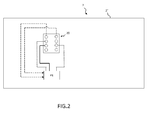
- the figure 2 is illustrated for information to represent a reverse side 2 "of a smart card 2.
- the smart card 2 comprises a chip P1 and an interface 20 comprising contacts as defined in the ISO7816 standard. associated with the chip are not represented as for example the associated memories.
- a smart card 2 of the invention therefore makes it possible to arrange the communication device of the invention on the back side, that is to say on the other side of the card comprising the chip traditionally positioned on the front side. .
Landscapes
- Engineering & Computer Science (AREA)
- Theoretical Computer Science (AREA)
- Physics & Mathematics (AREA)
- Computer Security & Cryptography (AREA)
- Computer Hardware Design (AREA)
- General Physics & Mathematics (AREA)
- Computer Networks & Wireless Communication (AREA)
- Signal Processing (AREA)
- Microelectronics & Electronic Packaging (AREA)
- Business, Economics & Management (AREA)
- General Engineering & Computer Science (AREA)
- Accounting & Taxation (AREA)
- Electromagnetism (AREA)
- Finance (AREA)
- Strategic Management (AREA)
- General Business, Economics & Management (AREA)
- Computing Systems (AREA)
- Calculators And Similar Devices (AREA)
- Credit Cards Or The Like (AREA)
- Optical Communication System (AREA)
Abstract
Le dispositif de communication 1 comprend une mémoire M permettant le stockage d'une clef numérique et d'un algorithme de diversification ; un calculateur D permettant de générer un code d'identification à partir d'au moins la clef numérique et de l'algorithme de diversification ; un afficheur 10 permettant l'affichage d'un code d'identification généré 101, 102, 103 par le calculateur. Le dispositif de communication comprend en outre un capteur de lumière 11 permettant de recevoir un signal lumineux 30.The communication device 1 comprises a memory M for storing a digital key and a diversification algorithm; a calculator D for generating an identification code from at least the digital key and the diversification algorithm; a display 10 for displaying a generated identification code 101, 102, 103 by the computer. The communication device further comprises a light sensor 11 for receiving a light signal 30.
Description
Le domaine de l'invention concerne les dispositifs permettant de sécuriser des transactions, notamment au moyen de la génération d'un code de sécurité. Plus précisément, le domaine de l'invention s'applique au domaine des cartes bancaires à afficheur comprenant des modules pour générer des codes de sécurisation de transaction.The field of the invention relates to devices for securing transactions, in particular by means of the generation of a security code. More specifically, the field of the invention applies to the field of bank cards display comprising modules for generating transaction security codes.
Actuellement, il existe déjà des solutions permettant de réaliser des cartes bancaires permettant de sécuriser des transactions faites par une simple identification de la carte par son numéro, sa date de validité et son titulaire par téléphone ou par internet.Currently, there are already solutions for making bank cards to secure transactions made by simply identifying the card by number, validity date and holder by phone or internet.
Un simple moyen de sécurisation d'une transaction est d'utiliser un cryptogramme visuel à 3 chiffres, également appelé CSC, CVV ou CVC ou encore V-code ou CCV. Nous utilisons dans la présente demande l'acronyme largement répandu et connu de l'homme de l'art « CVV » désignant : « Card Verification Value » dans la terminologie anglo-saxonne.A simple way to secure a transaction is to use a 3-digit visual cryptogram, also called CSC, CVV or CVC or V-code or CCV. We use in this application the acronym widely known and known to those skilled in the art "CVV" designating: "Card Verification Value" in the English terminology.
Un des problèmes de ce moyen de sécurisation est que le code est affiché de manière statique sur l'une des faces de la carte. De ce fait, le code peut être aisément lu par un tiers et peut être utilisé conjointement avec les autres informations collectées sur la carte.One of the problems of this means of securing is that the code is displayed statically on one of the faces of the card. As a result, the code can be easily read by a third party and can be used in conjunction with the other information collected on the card.
Pour améliorer la sécurité de ce type de transaction par carte bancaire, il est connu de rendre le code CVV dynamique. Le CVV dynamique correspond à un code variable dans le temps qui est affiché sur la carte. Le code variable est fournit par un générateur de type pseudo aléatoire synchronisé avec un serveur qui permet de vérifier l'authenticité du code en fonction de la date et de l'heure de la transaction.To improve the security of this type of credit card transaction, it is known to make the CVV code dynamic. Dynamic CVV is a time-varying code that is displayed on the map. The variable code is provided by a pseudo-random generator synchronized with a server which makes it possible to verify the authenticity of the code according to the date and time of the transaction.
Cependant, l'usage d'un CVV dynamique soulève quelques problèmes. Un premier problème vient de la personnalisation qui comprend l'introduction d'une clef de chiffrement numérique dans une mémoire du module d'affichage avant son intégration dans une carte à puce.However, the use of a dynamic CVV raises some problems. A first problem comes from the customization that includes the introduction of a digital encryption key in a display module memory before its integration into a smart card.
Cette solution est complexe d'un point de vue organisationnel car il est nécessaire de multiplier les opérations de traçage des modules de génération et d'affichage de codes CVV avec les numéros de cartes associées. Les numéros de carte n'étant pas forcément connu à ce stade, c'est-à-dire lors de la définition de la clef numérique dans le module, le suivi et l'attribution des modules deviennent complexe à mettre en oeuvre.This solution is complex from an organizational point of view because it is necessary to multiply the operations of tracing generation modules and displaying CVV codes with the associated card numbers. The card numbers are not necessarily known at this stage, that is to say when defining the digital key in the module, the tracking and allocation of modules become complex to implement.
Selon une alternative, il est possible de disposer de contacteurs externes pour la personnalisation du module de génération de codes CVV. Une fois la fabrication de la carte réalisée, la personnalisation a lieu avec un appareil externe qui permet de personnaliser une clef de chiffrement dans le module. En revanche, cette solution présente un inconvénient du point de vue de l'utilisation de la carte car les contacteurs peuvent occasionnés une gêne à l'utilisateur. Par ailleurs, visuellement, les contacteurs pénalisent le rendu esthétique de la carte.According to an alternative, it is possible to have external contactors for the customization of the CVV code generation module. Once the card has been manufactured, the customization takes place with an external device that makes it possible to customize an encryption key in the module. However, this solution has a disadvantage from the point of view of the use of the card because the contactors can cause discomfort to the user. In addition, visually, the contactors penalize the aesthetic rendering of the card.
Selon une autre alternative, le module de génération de codes CVV peut être associé à un module RF permettant d'établir une liaison avec un appareil externe qui permettrait une personnalisation après la réalisation de la carte. Cependant cette solution est couteuse et difficile à mettre en oeuvre, notamment dans le cadre d'une carte bancaire sans contact où l'un des modules créerait des interférences pour l'autre module.According to another alternative, the CVV code generation module can be associated with an RF module making it possible to establish a connection with an external device that would allow personalization after the production of the card. However, this solution is expensive and difficult to implement, especially in the context of a contactless bank card where one of the modules would create interference for the other module.
Selon une autre alternative, il est possible de coupler le module de génération de codes CVV avec la puce déjà intégrée sur une carte via les contacts ISO. En revanche, cette solution est difficile du point de vue de l'intégration. En outre, elle ne permet pas de dissocier les deux composants de la carte et de les rendre indépendants. L'indépendance des deux composants contribue à sécuriser l'environnement de la carte et rend plus difficile son piratage.According to another alternative, it is possible to couple the CVV code generation module with the chip already integrated on a card via the ISO contacts. On the other hand, this solution is difficult from the point of view of integration. In addition, it does not allow to separate the two components of the card and make them independent. The independence of the two components helps to secure the environment of the card and makes it more difficult to pirate.
Un deuxième problème est que, même avec un code CVV dynamique, il n'est pas possible de s'affranchir d'un vol des informations affichées sur la carte à puce. A titre d'exemple, lorsque la carte est visible d'un tiers, ce dernier peut recueillir les informations y compris le code CVV affiché dynamiquement et l'utiliser pendant la durée où le code est valide.A second problem is that, even with a dynamic CVV code, it is not possible to avoid a theft of information displayed on the smart card. For example, when the card is visible to a third party, the latter can collect the information including the dynamically displayed CVV code and use it during the time the code is valid.
Pour cela, il est proposé dans les solutions existantes des moyens de limiter ces vols d'informations. A titre d'exemple, il est possible de disposer d'un bouton permettant de générer l'affichage du code CVV sur l'afficheur uniquement lorsque l'on en a besoin. Cette solution comporte l'inconvénient d'être difficile à intégrer sur une carte à puce et le bouton peut constituer une gêne pour un utilisateur. Par ailleurs, il peut être activé par erreur ou par la personne mal intentionnée qui se trouve temporairement en possession de la carte.For this, it is proposed in the existing solutions means to limit these theft of information. For example, it is possible to have a button for generating the display of the CVV code on the display only when it is needed. This solution has the disadvantage of being difficult to integrate on a smart card and the button can be a nuisance for a user. In addition, it can be activated by mistake or by the malicious person who is temporarily in possession of the card.
Une autre solution consiste à déclencher périodiquement l'affichage, cette solution peut être couteuse en termes de consommation d'énergie. Par ailleurs, cette solution peut présenter des désagréments lors de transactions où il est nécessaire d'attendre le moment où le code va s'afficher. S'il est nécessaire d'attendre une trop longue période pour confirmer le paiement, cette solution n'est pas viable.Another solution is to periodically trigger the display, this solution can be expensive in terms of energy consumption. Moreover, this solution can present inconvenience during transactions where it is necessary to wait for the moment when the code will be displayed. If it is necessary to wait too long to confirm the payment, this solution is not viable.
L'invention permet de résoudre les inconvénients précités.The invention solves the aforementioned drawbacks.
Un objet de l'invention concerne un dispositif de communication comprenant :
- une mémoire permettant le stockage d'une clef numérique et un algorithme de diversification;
- un calculateur permettant de générer un code d'identification à partir d'au moins la clef numérique et de l'algorithme de diversification ;
- un afficheur permettant l'affichage d'un code d'identification généré par le calculateur.
- a memory for storing a digital key and a diversification algorithm;
- a calculator for generating an identification code from at least the digital key and the diversification algorithm;
- a display for displaying an identification code generated by the computer.
En outre, le dispositif de communication de l'invention comprend un capteur de lumière permettant de recevoir et/ou de détecter de la lumière.In addition, the communication device of the invention comprises a light sensor for receiving and / or detecting light.
Avantageusement, le capteur de lumière est destiné à recevoir un signal lumineux, le dispositif de communication assurant une fonction d'initialisation du dispositif, la fonction d'initialisation comprenant :
- un décodage d'une séquence de données modulant un signal lumineux reçu par le capteur de lumière ;
- un stockage de la clef numérique comprise dans la séquence numérique décodée.
- decoding a data sequence modulating a light signal received by the light sensor;
- a storage of the digital key included in the decoded digital sequence.
Un avantage est de permettre de personnaliser un dispositif tel qu'une carte à puce de manière sécurisée et simplement par un émetteur de type optique.One advantage is to make it possible to customize a device such as a smart card in a secure manner and simply by an optical type transmitter.
Un avantage est de faciliter la traçabilité d'un dispositif de communication avec une carte à puce lorsque ledit dispositif de communication est intégré dans une carte lors de sa fabrication. La clef numérique peut alors être associée à un numéro de carte après sa fabrication au moment de la personnalisation finale de la carte. Ainsi, le dispositif de communication est avantageusement un module de génération de codes d'identification, tel qu'un code de type CVV, dont la clef numérique constitue une graine d'initialisation d'algorithme de diversification.One advantage is to facilitate the traceability of a communication device with a smart card when said communication device is integrated in a card during its manufacture. The digital key can then be associated with a card number after its manufacture at the time of the final personalization of the card. Thus, the communication device is advantageously an identification code generation module, such as a CVV type code, the digital key of which constitutes a diversification algorithm initialization seed.
Selon un mode de réalisation de l'invention, le calculateur permet d'assurer une fonction d'activation de l'afficheur après une acquisition d'une intensité lumineuse reçue par le capteur de lumière pendant une durée prédéfinie.According to one embodiment of the invention, the computer makes it possible to ensure an activation function of the display after an acquisition of a light intensity received by the light sensor for a predefined duration.
Un avantage de cette fonction est de permettre d'obtenir un retard de l'affichage du code. Ce retard d'affichage peut être entendu comme une durée minimale d'activation qui peut ainsi constituer une protection de recopie du code par un tiers.An advantage of this function is to allow a delay in the display of the code. This display delay can be understood as a minimum activation period which can thus constitute a protection of copying of the code by a third party.
La quantité de lumière reçue peut être une intensité lumineuse reçue. Lorsque cette intensité lumineuse est intégrée sur une échelle de temps, elle peut définir une énergie reçue.The amount of light received may be a received light intensity. When this light intensity is integrated on a time scale, it can define a received energy.
La quantité de lumière reçue pendant une durée prédéfinie peut être mesurée selon les modes de réalisation par le capteur de lumière directement ou par le calculateur ou encore conjointement par ces deux derniers composants. A cet effet, le dispositif de communication peut comprendre une horloge, le calculateur pouvant déclencher un compteur de temps permettant d'assurer la mesure d'un flux lumineux pendant une durée donnée.The amount of light received for a predefined duration can be measured according to the embodiments by the light sensor directly. or by the computer or jointly by these last two components. For this purpose, the communication device may comprise a clock, the computer being able to trigger a time counter for measuring a luminous flux for a given duration.
Le dispositif de communication peut comparer l'intensité lumineuse reçue à chaque instant pendant la durée de l'acquisition ou selon un autre mode le dispositif de communication peut comparer l'énergie totale reçue pendant la durée de l'acquisition à un seuil d'énergie.The communication device can compare the light intensity received at any time during the acquisition time or in another mode the communication device can compare the total energy received during the acquisition time with an energy threshold. .
Avantageusement, le dispositif de communication comprend une batterie permettant d'assurer l'alimentation de l'afficheur et du calculateur. Ceci permet de rendre le dispositif de communication autonome. Sa faible consommation permet de lui garantir une durée de vie minimale au-delà de la durée généralement attribuée à une carte à puce définissant une date d'expiration.Advantageously, the communication device comprises a battery for providing power to the display and the computer. This makes the communication device autonomous. Its low consumption makes it possible to guarantee it a minimum lifetime beyond the duration generally attributed to a smart card defining an expiration date.
Avantageusement, le calculateur permet de générer le code d'identification à partir d'une donnée publique et de la clef numérique stockée dans la mémoire.Advantageously, the computer makes it possible to generate the identification code from a public data item and the digital key stored in the memory.
Cette génération permet d'augmenter la sécurité du code affiché et sa validité.This generation increases the security of the code displayed and its validity.
Avantageusement, la donnée publique est une donnée de date. Dans ce cas, le dispositif de communication comprend une horloge permettant de délivrer une date.Advantageously, the public data is a datum of date. In this case, the communication device comprises a clock for delivering a date.
Selon un mode de réalisation, le dispositif de communication de l'invention comprend une horloge permettant de déterminer des intervalles de temps et dans lequel l'afficheur permet l'affichage d'un code d'identification généré par le calculateur. L'affichage d'un code d'identification est avantageusement affiché après l'écoulement d'une durée de sécurité prédéterminée après la détection de lumière.According to one embodiment, the communication device of the invention comprises a clock for determining time intervals and in which the display allows the display of an identification code generated by the computer. The display of an identification code is advantageously displayed after the lapse of a predetermined security period after the detection of light.
Avantageusement, une génération d'un nouveau code d'identification est effectuée périodiquement.Advantageously, a generation of a new identification code is performed periodically.
Avantageusement, l'affichage d'un code d'identification est maintenu affiché pendant une durée d'affichage.Advantageously, the display of an identification code is maintained displayed during a display duration.
Lorsque cette solution est choisie, le serveur comprend également une horloge pour le contrôle du code d'identification, tel qu'un code CVV, et sa concordance avec la donnée correspondant à la donnée de la date qui a permis de générer le code CVV dynamique. Le serveur peut être configuré pour accepter une certaine tolérance notamment vis-à-vis de dérives d'heures de l'horloge utilisée dans le dispositif de communication.When this solution is chosen, the server also comprises a clock for the control of the identification code, such as a CVV code, and its concordance with the datum corresponding to the datum of the date which made it possible to generate the dynamic CVV code. . The server may be configured to accept a certain tolerance in particular with respect to drifts of hours of the clock used in the communication device.
Avantageusement, l'afficheur permet un affichage électro-phorétique. Cette solution permet de diminuer les consommations d'énergie notamment grâce à un état rémanent des données affichées.Advantageously, the display allows an electrophoretic display. This solution makes it possible to reduce the consumption of energy notably thanks to a residual state of the displayed data.
Avantageusement, la première durée prédéterminée est comprise entre 10 min et 2 jours et que la seconde durée prédéterminée est comprise entre 1 min et 10 min.Advantageously, the first predetermined duration is between 10 min and 2 days and the second predetermined duration is between 1 min and 10 min.
Un autre objet de l'invention concerne une carte à puce comprenant un dispositif de communication de l'invention.Another object of the invention relates to a smart card comprising a communication device of the invention.
Selon un mode de réalisation de l'invention, l'afficheur du dispositif de communication est positionné du même côté de la carte que le capteur de lumière.According to one embodiment of the invention, the display of the communication device is positioned on the same side of the card as the light sensor.
Un autre objet de l'invention concerne un procédé de réalisation d'une transaction à partir d'une carte à puce comprenant un dispositif comportant :
- une mémoire permettant le stockage d'une clef numérique et d'un algorithme de diversification ;
- un calculateur permettant de générer un code d'identification à partir de la clef numérique ;
- un afficheur permettant l'affichage d'un code d'identification généré par le calculateur ;
- un capteur de lumière permettant de recevoir et/ou de détecter de la lumière.
- a memory for storing a digital key and a diversification algorithm;
- a calculator for generating an identification code from the digital key;
- a display for displaying an identification code generated by the computer;
- a light sensor for receiving and / or detecting light.
Ledit procédé comprend les étapes suivantes :
- un positionnement de la carte à puce de sorte que le capteur de lumière soit exposé à une source lumineuse pendant une durée minimale ;
- un affichage d'un code sur l'afficheur après l'exposition pendant la durée minimale.
- positioning the smart card so that the light sensor is exposed to a light source for a minimum period of time;
- a display of a code on the display after exposure for the minimum duration.
Un avantage d'un tel procédé est de sécuriser la manoeuvre de validation du code d'identification en diminuant la durée pendant laquelle il peut être exposé à un tiers.One advantage of such a method is to secure the validation maneuver of the identification code by decreasing the duration during which it can be exposed to a third party.
Un autre objet de l'invention concerne un procédé de personnalisation d'une carte à puce comprenant un numéro de carte, ledit procédé comprenant:
- une affectation d'un dispositif de communication de l'invention à un numéro de carte à puce, un identifiant dudit dispositif de communication étant stocké sur un serveur distant et étant associé audit numéro de carte ;
- un montage du dispositif de communication sur ladite carte à puce
- une affectation d'une clef numérique à un dispositif de communication associé à un numéro de carte ;
- un transfert de la clef numérique par réception sur le capteur de lumière d'un signal lumineux modulé par une séquence de données lors de la personnalisation finale de la carte à puce.
- assigning a communication device of the invention to a chip card number, an identifier of said communication device being stored on a remote server and being associated with said card number;
- an assembly of the communication device on said smart card
- assigning a digital key to a communication device associated with a card number;
- a transfer of the digital key by reception on the light sensor of a light signal modulated by a sequence of data during the final personalization of the smart card.
Un avantage d'un tel procédé est qu'il n'est plus nécessaire de tracer des modules de génération de code d'identification avec leur carte par une association dès leur fabrication. Il est entendu dans ce cas que le dispositif de communication de l'invention est un module de génération de codes CVV. Le module de génération de CVV étant personnalisé lors de la personnalisation finale, la graine d'initialisation est facilement appairée au numéro de compte qui est inscrit sur la carte au même moment.An advantage of such a method is that it is no longer necessary to trace identification code generation modules with their card by an association as soon as they are manufactured. It is understood in this case that the communication device of the invention is a module for generating CVV codes. Since the CVV generation module is customized during final customization, the initialization seed is easily matched to the account number that is inscribed on the card at the same time.
Avantageusement, le transfert de la clef numérique comprend une émission d'un signal lumineux modulé par une séquence de données sur un capteur de lumière du dispositif de communication.Advantageously, the transfer of the digital key comprises an emission of a light signal modulated by a data sequence on a light sensor of the communication device.
D'autres caractéristiques et avantages de l'invention ressortiront à la lecture de la description détaillée qui suit, en référence aux figures annexées, qui illustrent :
- ■
figure 1 : le côté verso d'une carte à puce comprenant un dispositif de communication de l'invention ; - ■
figure 2 : le côté recto d'une carte à puce comprenant un dispositif de communication de l'invention.
- ■
figure 1 : the back side of a smart card comprising a communication device of the invention; - ■
figure 2 : the front side of a smart card comprising a communication device of the invention.
Dans la suite de la description on nomme un « capteur d'activation lumineux » plus généralement un « capteur de lumière ».In the following description is called a "light activation sensor" more generally a "light sensor".
On appelle indifféremment dans la présente demande une « clef de chiffrement », une « clef de chiffrement numérique » ou une « clef numérique ».In the present application, an "encryption key", a "digital encryption key" or a "digital key" is indifferently called.
La présente description illustre un mode de réalisation dans lequel le dispositif de communication est un générateur de codes CVV dynamiques. Nous nommons plus généralement dans la présente invention un code d'identification un code généré à partir d'une clef numérique pouvant être par exemple de type CVV.This description illustrates an embodiment in which the communication device is a generator of dynamic CVV codes. We more generally name in the present invention an identification code a code generated from a digital key that can be for example CVV type.
La
Le dispositif de l'invention comprend un capteur de lumière 11 capable de recevoir un flux lumineux 30.The device of the invention comprises a
Le capteur de lumière peut être un élément photo sensible tel qu'une photo transistor, une photo diode ou encore une cellule photo électrique. Préférentiellement, le capteur de lumière 11 est disposé du même côté de la carte que l'afficheur 10, lorsque le dispositif de communication est intégré à une carte à puce.The light sensor may be a photo sensitive element such as a photo transistor, a photo diode or a photoelectric cell. Preferably, the
Lorsque le dispositif de communication est intégré à une carte à puce, le capteur de lumière peut être disposé sous une partie translucide pour permettre une homogénéité de surface avec la surface d'une carte à puce. Selon un mode de réalisation, la partie translucide forme une partie de la surface de la carte. La partie translucide permet alors de protéger le capteur de lumière vis-à-vis d'un contact des mains ou des frottements pouvant être occasionnés lorsque la carte est mise dans une poche ou un porte-carte.When the communication device is integrated in a smart card, the light sensor can be arranged under a translucent portion to allow surface homogeneity with the surface of a smart card. According to one embodiment, the translucent portion forms part of the surface of the card. The translucent portion then allows to protect the light sensor vis-à-vis hand contact or friction that may be caused when the card is put in a pocket or a card holder.
Le capteur de lumière 11 est couplé à un calculateur D. Un afficheur 10 permet d'afficher un code d'identification de type code CVV dynamique. Une mémoire M permet de stocker une clef de chiffrement numérique K ainsi qu'un algorithme de diversification. Par ailleurs, une horloge 16 permet de délivrer une donnée d'heure. Selon un mode de réalisation de l'invention, la clef numérique et la donnée d'heure permettent de générer un code d'identification au moyen du calculateur D. La génération se fait par exemple selon un algorithme de diversification connu qui associe un code d'identification unique en fonction de la date ou qui génère un nouveau code à des dates données. Ce code d'identification est valable pendant une durée prédéfinie correspondant à un intervalle de temps entre deux générations de code d'identification. L'algorithme de diversification du code d'identification à partir du secret, constitué par la clef numérique, et d'une heure est exécuté par le calculateur D. Chaque code d'identification généré est donc différent d'un précédent code grâce à la donnée d'heure.The
Il existe d'autres alternatives permettant de générer un code d'identification à partir d'une clef de chiffrement et d'une donnée publique. La donnée publique est par exemple un nombre d'évènements, par exemple lorsqu'un porteur de carte incrémente par une action d'un compteur d'évènements. L'action peut être par exemple effectuée lors de chaque détection d'utilisation de la carte. Le compteur est également évalué coté serveur par exemple en dénombrant le nombre de transactions. Une tolérance doit dans ce cas être acceptée par le serveur. Le code peut donc être validé au moment de terminer la transaction.There are other alternatives for generating an identification code from an encryption key and a public data. The public data is for example a number of events, for example when a cardholder increments by an action of an event counter. The action can be performed for example during each detection of use of the card. The counter is also evaluated on the server side for example by counting the number of transactions. In this case, a tolerance must be accepted by the server. The code can be validated at the end of the transaction.
En ce sens, le dispositif de communication de l'invention est un générateur de codes d'identification, par exemple de codes CVV dynamiques. Le capteur lumineux permet son initialisation par la définition d'une graine et son stockage dans la mémoire du générateur de codes d'identification. Cette dernière étape peut être entendue comme une étape de personnalisation de la carte à puce et n'est réalisée à priori qu'une seule fois. En outre, le capteur lumineux permet d'effectuer un test de réception d'une intensité lumineuse pendant une durée donnée afin d'activer ou pas l'affichage du code généré lors de l'utilisation de la carte.In this sense, the communication device of the invention is a generator of identification codes, for example dynamic CVV codes. The light sensor allows its initialization by the definition of a seed and its storage in the memory of the identification code generator. This last step can be understood as a step of customization of the smart card and is performed a priori only once. In addition, the light sensor makes it possible to carry out a test of reception of a luminous intensity for a given duration in order to activate or not the display of the code generated during the use of the card.
L'afficheur ainsi que le calculateur peuvent être alimentés par une batterie BATT permettant d'afficher le code d'identification. Lorsque ce dernier code comporte 3 chiffres 101, 102, 103 tels que représentés sur la
Selon un premier mode du dispositif de communication de l'invention, une première fonction consiste à décoder une séquence lumineuse. Notons le « premier signal lumineux » le signal qui contient des données numériques qui modulent le premier signal. Cette première fonction est utilisée à l'initialisation, lors de la personnalisation de la carte, elle permet de définir, transmettre et stocker la clef de chiffrement numérique dans la mémoire M. Elle n'est à priori réalisée qu'une seule fois.According to a first mode of the communication device of the invention, a first function consists in decoding a light sequence. Note the "first light signal" the signal that contains digital data that modulates the first signal. This first function is used at initialization, during the personalization of the card, it allows to define, transmit and store the digital encryption key in the memory M. It is a priori performed only once.
La clef de chiffrement définie une graine permettant de rendre le code d'identification variable. La graine peut éventuellement comprendre d'autres éléments d'informations si nécessaire tel qu'un identifiant. Il est possible selon une variante de réalisation d'opérer une validation de la réception de la clef de chiffrement en retour par un affichage sur l'écran ou par LED.The encryption key defines a seed that makes the identification code variable. The seed may optionally include other pieces of information if necessary such as an identifier. It is possible according to a variant embodiment to operate a validation of the receipt of the encryption key in return by a display on the screen or by LED.
Selon un second mode du dispositif de communication de l'invention, une seconde fonction consiste à activer l'afficheur 10 après un temps d'exposition prédéterminé du capteur 11 à la lumière. Un avantage est de bénéficier de deux fonctions à des moments différents du cycle de vie de la carte à puce. Les deux fonctions étant supportées par un tel générateur de codes d'identification de l'invention.According to a second mode of the communication device of the invention, a second function consists in activating the
En phase d'utilisation, la seconde fonction de l'élément photo sensible est de détecter que la carte est exposée à la lumière côté afficheur pendant une durée déterminée afin d'autoriser l'affichage du code d'identification.In the use phase, the second function of the sensitive photo element is to detect that the card is exposed to the light on the display side for a specified period of time to allow the display of the identification code.
Notons le second signal lumineux, le signal qui permet d'activer l'afficheur, c'est-à-dire que pour une intensité de lumière reçue pendant une certaine durée, le calculateur D est capable d'activer l'affichage d'un code sur un afficheur 10. Cette seconde fonction est utilisée à chaque fois que l'utilisateur a besoin d'un code d'identification. Dans ce cas, il expose la face de la carte à puce 2 comportant le capteur à la lumière11 pendant un certain temps. Dans le cas de la
Les deux modes de réalisation sont supportés par le dispositif de communication de l'invention. Ils sont activés à différents moments. En ce qui concerne la première fonction, elle est activée lors de la personnalisation de la carte donc lors de la fabrication et la configuration de la carte. En ce qui concerne la seconde fonction, elle est activée à chaque nouvelle utilisation d'un porteur de carte afin de fournir un nouveau code d'identification.Both embodiments are supported by the communication device of the invention. They are activated at different times. Regarding the first function, it is activated during the customization of the card so during the manufacture and configuration of the card. As for the second function, it is activated each time a new cardholder is used to provide a new identification code.
Détaillons le fonctionnement de la première fonction. Selon une première variante de réalisation, le capteur de lumière comporte un composant permettant de démoduler le signal lumineux et d'en extraire une séquence numérique. Selon une seconde variante, le calculateur comprend une interface adaptée pour recevoir un signal analogique et le convertir en signal numérique. Le dispositif de communication de l'invention comprend donc un convertisseur de signal analogique / numérique qui peut être intégré au capteur de lumière 11 ou au calculateur D. Eventuellement, le convertisseur peut être un composant à part entière situé dans la chaine de réception entre le capteur de lumière 11 et le calculateur D.Let's detail the operation of the first function. According to a first variant embodiment, the light sensor comprises a component for demodulating the light signal and for extracting a digital sequence. According to a second variant, the computer comprises an interface adapted to receive an analog signal and convert it into a digital signal. The communication device of the invention therefore comprises an analog / digital signal converter that can be integrated in the
Selon des alternatives de réalisation, des composants permettant de quantifier ou de normaliser le signal reçu peuvent être utilisés dans le dispositif de communication de l'invention.According to alternative embodiments, components making it possible to quantify or standardize the received signal can be used in the communication device of the invention.
Lorsque le convertisseur est intégré au capteur 11, des données numériques sont transférées via la liaison 15 au calculateur D.When the converter is integrated in the
Le calculateur D permet d'extraire des informations de la séquence numérique reçue telle que la clef de chiffrement numérique. Cette dernière est alors stockée dans une mémoire M via une liaison 12. L'exemple de la
Lors de la phase de personnalisation, un émetteur approprié permettant d'envoyer une séquence d'information modulant un signal lumineux peut être spécialement utilisé lors de cette étape. L'émetteur est positionné en regard du capteur lumineux.During the customization phase, a suitable transmitter for sending an information sequence modulating a light signal can be specially used during this step. The transmitter is positioned next to the light sensor.
Détaillons le fonctionnement de la seconde fonction.Let's detail the operation of the second function.
Lorsque l'utilisateur souhaite générer un code d'identification dynamique par exemple à trois chiffres pour sécuriser une transaction, il positionne la carte à puce 2, face 2', de sorte à exposer le capteur 11 à la lumière pendant une durée donnée. Cette durée peut être de l'ordre de quelques secondes.When the user wishes to generate a dynamic identification code, for example three digits to secure a transaction, it positions the
Le capteur de lumière acquiert un flux lumineux 30 et mesure l'intensité lumineuse reçue intégrée sur une période de temps donné. Lorsque l'intensité dépasse un seuil prédéfini pendant la durée donnée, alors un signal peut être transmis soit directement à l'afficheur 10 soit au calculateur D. Cette dernière solution correspond au mode décrit à la
Le calculateur D active alors l'affichage d'un code d'identification. Cette activation peut être comprise comme une « autorisation d'affichage ».The computer D then activates the display of an identification code. This activation can be understood as a "display authorization".
Pour réaliser cette seconde fonction, contrairement à la première fonction, le signal lumineux reçu ne module pas nécessairement une séquence de données. Seule une durée ou un niveau d'énergie lumineuse est nécessaire à l'activation de l'affichage d'un code d'identification.To perform this second function, unlike the first function, the received light signal does not necessarily modulate a data sequence. Only a duration or a level of light energy is necessary to activate the display of an identification code.
Selon un mode de réalisation, une horloge permet de déterminer des intervalles de temps et de générer des nouveaux codes régulièrement ou de manière pseudo aléatoire dans le temps.According to one embodiment, a clock makes it possible to determine time intervals and to generate new codes regularly or in a pseudo-random manner over time.
Cette solution permet d'augmenter la sécurité de l'usage d'une carte à puce bancaire par exemple. Chaque code d'identification affiché est alors à usage unique.This solution makes it possible to increase the security of the use of a bank smart card for example. Each identification code displayed is then for single use only.
L'affichage d'un code d'identification à usage unique est affiché après l'écoulement d'une durée de sécurité prédéterminée de sorte à ne pas exposer le code d'identification trop rapidement à un tiers.The display of a one-time identification code is displayed after the lapse of a predetermined security period so as not to expose the identification code too quickly to a third party.
En outre, une fois le code d'identification affiché, une fonction optionnelle peut être implémentée de sorte à maintenir l'affichage de ce code pendant une certaine durée prolongée. Cette fonction dite « de gèle » permet de geler l'affichage d'un nouveau code d'identification pendant la lecture du précédent code d'identification.In addition, once the identification code is displayed, an optional function may be implemented to maintain the display of this code for a certain extended duration. This so-called "freeze" function freezes the display of a new identification code during the reading of the previous identification code.
Selon un mode de réalisation, le code d'identification est généré à partir de la clef de chiffrement et d'une donnée d'heure. La clef de chiffrement est stockée dans la mémoire M, elle peut être lue par le calculateur D au moment où ce dernier est sollicité pour afficher le code d'identification. La clef et la donnée d'heure transmise via la liaison 14 peuvent être des données d'entrées d'un algorithme permettant de générer un code d'identification valide.According to one embodiment, the identification code is generated from the encryption key and a time data. The encryption key is stored in the memory M, it can be read by the computer D when the latter is requested to display the identification code. The key and the time data transmitted via the
Dans d'autres modes de réalisation, le code d'identification comporte N digits et n'est pas limité à 3 chiffres.In other embodiments, the identification code has N digits and is not limited to 3 digits.
La
Une carte à puce 2 de l'invention permet donc de disposer le dispositif de communication de l'invention sur le côté verso, c'est-à-dire sur l'autre face de la carte comprenant la puce traditionnellement positionnée sur le côté recto.A
L'invention permet :
- de résoudre de façon optimum du point de vue la complexité de la solution et de l'utilisation le chargement d'informations dans un module de génération de codes CVV ;
- de faciliter de fabrication d'une carte et d'en réduire le coût ;
- d'apporter une sécurité supplémentaire pour le CVV à moindre coût.
- optimally solving from the point of view of the complexity of the solution and the use of loading information into a CVV generation module;
- to facilitate the manufacture of a card and to reduce the cost thereof;
- to provide additional security for CVV at a lower cost.
Claims (13)
caractérisé en ce que le procédé comprend :
characterized in that the method comprises:
Priority Applications (5)
| Application Number | Priority Date | Filing Date | Title |
|---|---|---|---|
| EP14151152.7A EP2889854A1 (en) | 2013-12-30 | 2014-01-14 | Communication device comprising a light-activation sensor |
| EP14805937.1A EP3090421A1 (en) | 2013-12-30 | 2014-12-03 | Communication device comprising a luminous activation sensor |
| PCT/EP2014/076348 WO2015101457A1 (en) | 2013-12-30 | 2014-12-03 | Communication device comprising a luminous activation sensor |
| US15/109,367 US20160328716A1 (en) | 2013-12-30 | 2014-12-03 | Communication device comprising a luminous activation sensor |
| JP2016543599A JP2017509042A (en) | 2013-12-30 | 2014-12-03 | Communication device with optical activation sensor |
Applications Claiming Priority (2)
| Application Number | Priority Date | Filing Date | Title |
|---|---|---|---|
| EP13306894 | 2013-12-30 | ||
| EP14151152.7A EP2889854A1 (en) | 2013-12-30 | 2014-01-14 | Communication device comprising a light-activation sensor |
Publications (1)
| Publication Number | Publication Date |
|---|---|
| EP2889854A1 true EP2889854A1 (en) | 2015-07-01 |
Family
ID=50002442
Family Applications (2)
| Application Number | Title | Priority Date | Filing Date |
|---|---|---|---|
| EP14151152.7A Withdrawn EP2889854A1 (en) | 2013-12-30 | 2014-01-14 | Communication device comprising a light-activation sensor |
| EP14805937.1A Withdrawn EP3090421A1 (en) | 2013-12-30 | 2014-12-03 | Communication device comprising a luminous activation sensor |
Family Applications After (1)
| Application Number | Title | Priority Date | Filing Date |
|---|---|---|---|
| EP14805937.1A Withdrawn EP3090421A1 (en) | 2013-12-30 | 2014-12-03 | Communication device comprising a luminous activation sensor |
Country Status (4)
| Country | Link |
|---|---|
| US (1) | US20160328716A1 (en) |
| EP (2) | EP2889854A1 (en) |
| JP (1) | JP2017509042A (en) |
| WO (1) | WO2015101457A1 (en) |
Families Citing this family (2)
| Publication number | Priority date | Publication date | Assignee | Title |
|---|---|---|---|---|
| EP3217343A1 (en) * | 2016-03-08 | 2017-09-13 | Gemalto Sa | A method to compensate by a server a clock deviation of a card |
| FR3090935B1 (en) * | 2018-12-19 | 2022-04-29 | Idemia France | METHOD FOR DETERMINING CHIP CARD BEHAVIOR, AND ASSOCIATED SERVER |
Citations (2)
| Publication number | Priority date | Publication date | Assignee | Title |
|---|---|---|---|---|
| WO2009056897A1 (en) * | 2007-10-30 | 2009-05-07 | Telecom Italia S.P.A | Method of authentication of users in data processing systems |
| US20120153028A1 (en) * | 2010-12-15 | 2012-06-21 | Poznansky Amir | Transaction Card with dynamic CVV |
Family Cites Families (12)
| Publication number | Priority date | Publication date | Assignee | Title |
|---|---|---|---|---|
| JP2546983B2 (en) * | 1984-10-11 | 1996-10-23 | 豊 塚本 | Digital signature generation system |
| IL141441A0 (en) * | 2001-02-15 | 2002-03-10 | Aharonson Dov | Smart card having an optical communication circuit and a method for use thereof |
| JP2003168095A (en) * | 2001-11-30 | 2003-06-13 | Toppan Printing Co Ltd | Non-contact ic card with display function and method for controlling its display time |
| JP4646050B2 (en) * | 2004-05-06 | 2011-03-09 | 大日本印刷株式会社 | Method to issue IC card and perform encryption / decryption |
| DE102006027462B4 (en) * | 2006-06-12 | 2009-06-18 | Nec Europe Ltd. | Method for operating a wireless sensor network |
| US9251637B2 (en) * | 2006-11-15 | 2016-02-02 | Bank Of America Corporation | Method and apparatus for using at least a portion of a one-time password as a dynamic card verification value |
| JP2008198147A (en) * | 2007-02-16 | 2008-08-28 | Dainippon Printing Co Ltd | Method for adjusting time of token for generating one-time password of time synchronous system, token provided with function for securely correcting clock time, and server for generating message for correcting token time |
| JP2010204809A (en) * | 2009-03-02 | 2010-09-16 | Toppan Printing Co Ltd | Usb type token |
| JP2010257422A (en) * | 2009-04-28 | 2010-11-11 | Dainippon Printing Co Ltd | Card type one time password generator and initial issuing method |
| CA3117923A1 (en) * | 2010-07-29 | 2012-02-02 | Dynamics Inc. | Payment cards, devices, systems, and methods for providing game actions with payment data, social networking mechanisms and information exchange mechanisms |
| US9330606B2 (en) * | 2012-06-08 | 2016-05-03 | Apple Inc. | Electronic device with display brightness control |
| US9064195B2 (en) * | 2012-06-29 | 2015-06-23 | Dynamics Inc. | Multiple layer card circuit boards |
-
2014
- 2014-01-14 EP EP14151152.7A patent/EP2889854A1/en not_active Withdrawn
- 2014-12-03 WO PCT/EP2014/076348 patent/WO2015101457A1/en active Application Filing
- 2014-12-03 JP JP2016543599A patent/JP2017509042A/en not_active Ceased
- 2014-12-03 EP EP14805937.1A patent/EP3090421A1/en not_active Withdrawn
- 2014-12-03 US US15/109,367 patent/US20160328716A1/en not_active Abandoned
Patent Citations (2)
| Publication number | Priority date | Publication date | Assignee | Title |
|---|---|---|---|---|
| WO2009056897A1 (en) * | 2007-10-30 | 2009-05-07 | Telecom Italia S.P.A | Method of authentication of users in data processing systems |
| US20120153028A1 (en) * | 2010-12-15 | 2012-06-21 | Poznansky Amir | Transaction Card with dynamic CVV |
Non-Patent Citations (3)
| Title |
|---|
| PEPIJN PINKSE: "Quantum Credit card", 31 January 2013 (2013-01-31), XP055168636, Retrieved from the Internet <URL:http://www.utwente.nl/mesaplus/archive/2013/1/272924/vici-quantum-credit-card> [retrieved on 20150210] * |
| SEBASTIANUS A GOORDEN ET AL: "Quantum-Secure Authentication with a Classical Key", 1 March 2013 (2013-03-01), XP055168644, Retrieved from the Internet <URL:http://arxiv.org/abs/1303.0142> DOI: 10.1364/OPTICA.1.000421 * |
| SKORIC B: "Security analysis of Quantum-Readout PUFs in the case of generic challenge-estimation attacks", INTERNATIONAL ASSOCIATION FOR CRYPTOLOGIC RESEARCH,, vol. 20130814:143926, 7 August 2013 (2013-08-07), pages 1 - 10, XP061007989 * |
Also Published As
| Publication number | Publication date |
|---|---|
| US20160328716A1 (en) | 2016-11-10 |
| JP2017509042A (en) | 2017-03-30 |
| WO2015101457A1 (en) | 2015-07-09 |
| EP3090421A1 (en) | 2016-11-09 |
Similar Documents
| Publication | Publication Date | Title |
|---|---|---|
| WO2017198842A1 (en) | Device for dynamically generating and displaying a security code | |
| EP3794538B1 (en) | Method and system of autonomous enrolment for biometric device holder | |
| CA2702013C (en) | Contactless biometric authentication system and authentication method | |
| EP2577568B1 (en) | Bank card with display screen | |
| FR2989802B1 (en) | CARD WITH DISPLAY FUNCTION HAVING SECURITY AUTHENTICATION FUNCTION | |
| EP2065857A2 (en) | Microprocessor card, telephone comprising such a card and method of executing a command on such a card | |
| CA2676236C (en) | Portable authentication device | |
| EP1210689A1 (en) | Smart card architecture incorporating peripherals | |
| EP2065858A2 (en) | Microprocessor card, telephone comprising such a card and method of executing a command on such a card | |
| CA2939016A1 (en) | Electronic transaction method and system via a portable accessory | |
| CH713463B1 (en) | Smart card comprising a measuring circuit with a sensor. | |
| FR2923632A1 (en) | MICROPROCESSOR CARD, TELEPHONE INCLUDING SUCH CARD AND PROCESSING METHOD IN SUCH CARD. | |
| EP2889854A1 (en) | Communication device comprising a light-activation sensor | |
| EP3729383B1 (en) | Aggregator of identification devices | |
| EP2577574B1 (en) | Bank card with display screen | |
| FR2828755A1 (en) | DEVICE AND METHOD FOR RECOGNIZING AT LEAST ONE PERSON, CORRESPONDING ACCESS CONTROL DEVICE AND SYSTEM AND APPLICATION | |
| FR3000263A1 (en) | DETECTION OF A TRANSACTIONAL DEVICE | |
| EP2889809A1 (en) | Device for converting an electromagnetic field | |
| EP4006803A1 (en) | Portable object for contactless payment | |
| CH718102A2 (en) | Portable contactless payment object. | |
| FR3095111A1 (en) | CONNECTED ELECTRONIC CARD HOLDER AND CARD MANAGEMENT SYSTEM | |
| EP3472758A1 (en) | Method implemented in an electronic entity and associated electronic entity | |
| FR3139928A1 (en) | Contactless smart card equipped with a three-dimensional position sensor. | |
| WO2023170186A1 (en) | Portable, self-contained device for securing data transfer and corresponding method | |
| FR3003640A1 (en) | SYSTEM FOR MONITORING A QUANTITY OF SOLAR RADIATION RECEIVED BY A USER. |
Legal Events
| Date | Code | Title | Description |
|---|---|---|---|
| PUAI | Public reference made under article 153(3) epc to a published international application that has entered the european phase |
Free format text: ORIGINAL CODE: 0009012 |
|
| 17P | Request for examination filed |
Effective date: 20140114 |
|
| AK | Designated contracting states |
Kind code of ref document: A1 Designated state(s): AL AT BE BG CH CY CZ DE DK EE ES FI FR GB GR HR HU IE IS IT LI LT LU LV MC MK MT NL NO PL PT RO RS SE SI SK SM TR |
|
| AX | Request for extension of the european patent |
Extension state: BA ME |
|
| STAA | Information on the status of an ep patent application or granted ep patent |
Free format text: STATUS: THE APPLICATION IS DEEMED TO BE WITHDRAWN |
|
| 18D | Application deemed to be withdrawn |
Effective date: 20160105 |