EP2889747A1 - Electronic device - Google Patents
Electronic device Download PDFInfo
- Publication number
- EP2889747A1 EP2889747A1 EP14185298.8A EP14185298A EP2889747A1 EP 2889747 A1 EP2889747 A1 EP 2889747A1 EP 14185298 A EP14185298 A EP 14185298A EP 2889747 A1 EP2889747 A1 EP 2889747A1
- Authority
- EP
- European Patent Office
- Prior art keywords
- surface touch
- touch sensor
- display region
- user
- touched
- Prior art date
- Legal status (The legal status is an assumption and is not a legal conclusion. Google has not performed a legal analysis and makes no representation as to the accuracy of the status listed.)
- Withdrawn
Links
Images








Classifications
-
- G—PHYSICS
- G06—COMPUTING OR CALCULATING; COUNTING
- G06F—ELECTRIC DIGITAL DATA PROCESSING
- G06F3/00—Input arrangements for transferring data to be processed into a form capable of being handled by the computer; Output arrangements for transferring data from processing unit to output unit, e.g. interface arrangements
- G06F3/01—Input arrangements or combined input and output arrangements for interaction between user and computer
- G06F3/03—Arrangements for converting the position or the displacement of a member into a coded form
- G06F3/041—Digitisers, e.g. for touch screens or touch pads, characterised by the transducing means
- G06F3/0416—Control or interface arrangements specially adapted for digitisers
- G06F3/0418—Control or interface arrangements specially adapted for digitisers for error correction or compensation, e.g. based on parallax, calibration or alignment
-
- G—PHYSICS
- G04—HOROLOGY
- G04G—ELECTRONIC TIME-PIECES
- G04G21/00—Input or output devices integrated in time-pieces
- G04G21/08—Touch switches specially adapted for time-pieces
-
- G—PHYSICS
- G06—COMPUTING OR CALCULATING; COUNTING
- G06F—ELECTRIC DIGITAL DATA PROCESSING
- G06F1/00—Details not covered by groups G06F3/00 - G06F13/00 and G06F21/00
- G06F1/16—Constructional details or arrangements
- G06F1/1613—Constructional details or arrangements for portable computers
- G06F1/163—Wearable computers, e.g. on a belt
-
- G—PHYSICS
- G06—COMPUTING OR CALCULATING; COUNTING
- G06F—ELECTRIC DIGITAL DATA PROCESSING
- G06F1/00—Details not covered by groups G06F3/00 - G06F13/00 and G06F21/00
- G06F1/16—Constructional details or arrangements
- G06F1/1613—Constructional details or arrangements for portable computers
- G06F1/1633—Constructional details or arrangements of portable computers not specific to the type of enclosures covered by groups G06F1/1615 - G06F1/1626
- G06F1/1637—Details related to the display arrangement, including those related to the mounting of the display in the housing
- G06F1/1643—Details related to the display arrangement, including those related to the mounting of the display in the housing the display being associated to a digitizer, e.g. laptops that can be used as penpads
-
- G—PHYSICS
- G06—COMPUTING OR CALCULATING; COUNTING
- G06F—ELECTRIC DIGITAL DATA PROCESSING
- G06F1/00—Details not covered by groups G06F3/00 - G06F13/00 and G06F21/00
- G06F1/16—Constructional details or arrangements
- G06F1/1613—Constructional details or arrangements for portable computers
- G06F1/1633—Constructional details or arrangements of portable computers not specific to the type of enclosures covered by groups G06F1/1615 - G06F1/1626
- G06F1/1684—Constructional details or arrangements related to integrated I/O peripherals not covered by groups G06F1/1635 - G06F1/1675
- G06F1/169—Constructional details or arrangements related to integrated I/O peripherals not covered by groups G06F1/1635 - G06F1/1675 the I/O peripheral being an integrated pointing device, e.g. trackball in the palm rest area, mini-joystick integrated between keyboard keys, touch pads or touch stripes
-
- G—PHYSICS
- G06—COMPUTING OR CALCULATING; COUNTING
- G06F—ELECTRIC DIGITAL DATA PROCESSING
- G06F3/00—Input arrangements for transferring data to be processed into a form capable of being handled by the computer; Output arrangements for transferring data from processing unit to output unit, e.g. interface arrangements
- G06F3/01—Input arrangements or combined input and output arrangements for interaction between user and computer
- G06F3/03—Arrangements for converting the position or the displacement of a member into a coded form
- G06F3/041—Digitisers, e.g. for touch screens or touch pads, characterised by the transducing means
- G06F3/0412—Digitisers structurally integrated in a display
-
- G—PHYSICS
- G06—COMPUTING OR CALCULATING; COUNTING
- G06F—ELECTRIC DIGITAL DATA PROCESSING
- G06F3/00—Input arrangements for transferring data to be processed into a form capable of being handled by the computer; Output arrangements for transferring data from processing unit to output unit, e.g. interface arrangements
- G06F3/01—Input arrangements or combined input and output arrangements for interaction between user and computer
- G06F3/048—Interaction techniques based on graphical user interfaces [GUI]
- G06F3/0481—Interaction techniques based on graphical user interfaces [GUI] based on specific properties of the displayed interaction object or a metaphor-based environment, e.g. interaction with desktop elements like windows or icons, or assisted by a cursor's changing behaviour or appearance
- G06F3/04812—Interaction techniques based on cursor appearance or behaviour, e.g. being affected by the presence of displayed objects
-
- G—PHYSICS
- G06—COMPUTING OR CALCULATING; COUNTING
- G06F—ELECTRIC DIGITAL DATA PROCESSING
- G06F3/00—Input arrangements for transferring data to be processed into a form capable of being handled by the computer; Output arrangements for transferring data from processing unit to output unit, e.g. interface arrangements
- G06F3/01—Input arrangements or combined input and output arrangements for interaction between user and computer
- G06F3/048—Interaction techniques based on graphical user interfaces [GUI]
- G06F3/0484—Interaction techniques based on graphical user interfaces [GUI] for the control of specific functions or operations, e.g. selecting or manipulating an object, an image or a displayed text element, setting a parameter value or selecting a range
- G06F3/04842—Selection of displayed objects or displayed text elements
-
- G—PHYSICS
- G06—COMPUTING OR CALCULATING; COUNTING
- G06F—ELECTRIC DIGITAL DATA PROCESSING
- G06F3/00—Input arrangements for transferring data to be processed into a form capable of being handled by the computer; Output arrangements for transferring data from processing unit to output unit, e.g. interface arrangements
- G06F3/01—Input arrangements or combined input and output arrangements for interaction between user and computer
- G06F3/048—Interaction techniques based on graphical user interfaces [GUI]
- G06F3/0484—Interaction techniques based on graphical user interfaces [GUI] for the control of specific functions or operations, e.g. selecting or manipulating an object, an image or a displayed text element, setting a parameter value or selecting a range
- G06F3/0486—Drag-and-drop
-
- G—PHYSICS
- G06—COMPUTING OR CALCULATING; COUNTING
- G06F—ELECTRIC DIGITAL DATA PROCESSING
- G06F3/00—Input arrangements for transferring data to be processed into a form capable of being handled by the computer; Output arrangements for transferring data from processing unit to output unit, e.g. interface arrangements
- G06F3/01—Input arrangements or combined input and output arrangements for interaction between user and computer
- G06F3/048—Interaction techniques based on graphical user interfaces [GUI]
- G06F3/0487—Interaction techniques based on graphical user interfaces [GUI] using specific features provided by the input device, e.g. functions controlled by the rotation of a mouse with dual sensing arrangements, or of the nature of the input device, e.g. tap gestures based on pressure sensed by a digitiser
- G06F3/0488—Interaction techniques based on graphical user interfaces [GUI] using specific features provided by the input device, e.g. functions controlled by the rotation of a mouse with dual sensing arrangements, or of the nature of the input device, e.g. tap gestures based on pressure sensed by a digitiser using a touch-screen or digitiser, e.g. input of commands through traced gestures
- G06F3/04883—Interaction techniques based on graphical user interfaces [GUI] using specific features provided by the input device, e.g. functions controlled by the rotation of a mouse with dual sensing arrangements, or of the nature of the input device, e.g. tap gestures based on pressure sensed by a digitiser using a touch-screen or digitiser, e.g. input of commands through traced gestures for inputting data by handwriting, e.g. gesture or text
-
- G—PHYSICS
- G06—COMPUTING OR CALCULATING; COUNTING
- G06F—ELECTRIC DIGITAL DATA PROCESSING
- G06F2203/00—Indexing scheme relating to G06F3/00 - G06F3/048
- G06F2203/033—Indexing scheme relating to G06F3/033
- G06F2203/0339—Touch strips, e.g. orthogonal touch strips to control cursor movement or scrolling; single touch strip to adjust parameter or to implement a row of soft keys
-
- G—PHYSICS
- G06—COMPUTING OR CALCULATING; COUNTING
- G06F—ELECTRIC DIGITAL DATA PROCESSING
- G06F2203/00—Indexing scheme relating to G06F3/00 - G06F3/048
- G06F2203/048—Indexing scheme relating to G06F3/048
- G06F2203/04803—Split screen, i.e. subdividing the display area or the window area into separate subareas
-
- G—PHYSICS
- G06—COMPUTING OR CALCULATING; COUNTING
- G06F—ELECTRIC DIGITAL DATA PROCESSING
- G06F2203/00—Indexing scheme relating to G06F3/00 - G06F3/048
- G06F2203/048—Indexing scheme relating to G06F3/048
- G06F2203/04806—Zoom, i.e. interaction techniques or interactors for controlling the zooming operation
-
- G—PHYSICS
- G06—COMPUTING OR CALCULATING; COUNTING
- G06F—ELECTRIC DIGITAL DATA PROCESSING
- G06F2203/00—Indexing scheme relating to G06F3/00 - G06F3/048
- G06F2203/048—Indexing scheme relating to G06F3/048
- G06F2203/04808—Several contacts: gestures triggering a specific function, e.g. scrolling, zooming, right-click, when the user establishes several contacts with the surface simultaneously; e.g. using several fingers or a combination of fingers and pen
Definitions
- Example embodiments relate generally to an electronic device. More particularly, embodiments of the present inventive concept relate to an electronic device including a touch screen.
- a touch screen e.g., a mobile device such as a cellular phone, a smart phone, a smart pad, etc.
- a watch-shaped mobile device e.g., referred to as a smart watch
- the size of a front-surface touch screen included in the watch-shaped mobile device has limits, unlike the mobile device such as the cellular phone, the smart phone, the smart pad, etc.
- the front-surface touch screen included in the watch-shaped mobile device has a relatively small size (e.g., about 3.302 cm).
- the user-command may not be accurately and precisely input to the mobile device.
- the user-command may be erroneously input to the mobile device.
- Some example embodiments provide an electronic device capable of allowing a user to accurately and precisely input a user-command to the electronic device although the electronic device includes a front-surface touch screen having a relatively small size.
- an electronic device may include a front-surface touch screen; a plurality of side-surface touch sensors configured to receive a user-command; and a body including a processor for processing the user-command, wherein the body is combined with the front-surface touch screen and the side-surface touch sensors.
- the user-command may include an operation in which at least one of the side-surface touch sensors is touched by a user for more than an activation time, and an operation in which a touched point of the at least one of the side-surface touch sensors is moved by the user.
- the side-surface touch sensors may include a left side-surface touch sensor, a right side-surface touch sensor, an upper side-surface touch sensor, and a lower side-surface touch sensor with respect to a center of the body.
- the electronic device may correspond to a watch-shaped mobile device that the user wears on a wrist.
- a first pointer line extended from a first touched point of the left side-surface touch sensor or the right side-surface touch sensor, and a second pointer line extended from a second touched point of the upper side-surface touch sensor or the lower side-surface touch sensor may be displayed on the front-surface touch screen when one of the left side-surface touch sensor and the right side-surface touch sensor, and one of the upper side-surface touch sensor and the lower side-surface touch sensor are concurrently touched by the user for more than the activation time.
- a pointer may be displayed at a crossing point of the first pointer line and the second pointer line on the front-surface touch screen.
- the pointer, the first pointer line, and the second pointer line may be moved on the front-surface touch screen as the first touched point and the second touched point are moved by the user.
- the pointer, the first pointer line, and the second pointer line may disappear from the front-surface touch screen when a deactivation time elapses after the first touched point and the second touched point have been moved by the user.
- the processor may perform a click operation on contents at which the pointer points when the front-surface touch screen is touched by the user while the pointer, the first pointer line, and the second pointer line are displayed on the front-surface touch screen.
- the processor may perform a first click operation on the contents when a first region of the front-surface touch screen is touched by the user while the pointer, the first pointer line, and the second pointer line are displayed on the front-surface touch screen, wherein the first region is a region within a reference distance from the pointer.
- the processor may perform a second click operation on the contents when a second region of the front-surface touch screen is touched by the user while the pointer, the first pointer line, and the second pointer line are displayed on the front-surface touch screen, wherein the second region is a region outside the reference distance from the pointer.
- the first click operation may correspond to a left click operation of a computer mouse device
- the second click operation may correspond to a right click operation of the computer mouse device
- the processor may perform a drag operation on the contents when, the side-surface touch sensors are touched again by the user within a reactivation time after touches on the side-surface touch sensors are released by the user, and the first touched point and the second touched point are moved while the pointer, the first pointer line, and the second pointer line are displayed on the front-surface touch screen.
- the reactivation time may be shorter than the activation time.
- a first division line coupled between a first touched point of the left side-surface touch sensor and a second touched point of the right side-surface touch sensor may be displayed on the front-surface touch screen when the left side-surface touch sensor and the right side-surface touch sensor are concurrently touched by the user for more than the activation time.
- a second division line coupled between a third touched point of the upper side-surface touch sensor and a fourth touched point of the lower side-surface touch sensor may be displayed on the front-surface touch screen when the upper side-surface touch sensor and the lower side-surface touch sensor are concurrently touched by the user for more than the activation time.
- the first division line may be moved on the front-surface touch screen as the first touched point and the second touched point are moved by the user.
- the second division line may be moved on the front-surface touch screen as the third touched point and the fourth touched point are moved by the user.
- a display region of the front-surface touch screen may be divided into an upper display region and a lower display region by the first division line, and may be divided into a left display region and a right display region by the second division line.
- the first division line may disappear from the front-surface touch screen when a deactivation time elapses after the first touched point and the second touched point have been moved by the user.
- the second division line may disappear from the front-surface touch screen when the deactivation time elapses after the third touched point and the fourth touched point have been moved by the user.
- the first division line may be displayed again on the front-surface touch screen when the left side-surface touch sensor and the right side-surface touch sensor are concurrently touched by the user for more than the activation time while the display region of the front-surface touch screen is divided into the upper display region and the lower display region.
- the upper display region and the lower display region may be relatively adjusted as the first touched point and the second touched point are moved by the user.
- the second division line may be displayed again on the front-surface touch screen when the upper side-surface touch sensor and the lower side-surface touch sensor are concurrently touched by the user for more than the activation time while the display region of the front-surface touch screen is divided into the left display region and the right display region.
- the left display region and the right display region may be relatively adjusted as the third touched point and the fourth touched point are moved by the user.
- the first division line or the second division line may be partially displayed again on the front-surface touch screen when the left side-surface touch sensor, the right side-surface touch sensor, the upper side-surface touch sensor, or the lower side-surface touch sensor is touched by the user for more than the activation time while the display region of the front-surface touch screen is divided into the left display region, the right display region, the upper display region, and the lower display region.
- the left and right display regions or the upper and lower display regions may be relatively adjusted as the first touched point, the second touched point, the third touched point, or the fourth touched point is moved by the user.
- the first division line or the second division line may be displayed again on the front-surface touch screen when the left side-surface touch sensor and the right side-surface touch sensor are concurrently touched in a staggered manner by the user for more than the activation time, or when the upper side-surface touch sensor and the lower side-surface touch sensor are concurrently touched in a staggered manner by the user for more than the activation time while the display region of the front-surface touch screen is divided into the left display region, the right display region, the upper display region, and the lower display region.
- the left display region, the right display region, the upper display region, and the lower display region may be rotated about a crossing point of the first division line and the second division line as the first touched point, the second touched point, the third touched point, or the fourth touched point is moved by the user.
- a target display region may be determined when one of the left display region, the right display region, the upper display region, and the lower display region is touched by the user after one of the left side-surface touch sensor and the right side-surface touch sensor, and one of the upper side-surface touch sensor and the lower side-surface touch sensor are concurrently touched by the user for more than the activation time while the display region of the front-surface touch screen is divided into the left display region, the right display region, the upper display region, and the lower display region.
- the target display region may be zoomed-in or zoomed-out as the first touched point, the second touched point, the third touched point, or the fourth touched point is moved by the user.
- an electronic device may allow a user to accurately and precisely input the user-command to the electronic device because the electronic device receives the user-command based on an operation in which at least one of the side-surface touch sensors is touched by the user for more than an activation time and an operation in which a touched point of respective side-surface touch sensors is dragged (e.g., moved) by the user.
- FIG. 1 is a block diagram illustrating an electronic device according to example embodiments.
- FIG. 2 is a diagram illustrating an example in which the electronic device of FIG. 1 is implemented as a watch-shaped mobile device.
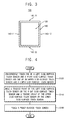
- FIG. 3 is a diagram illustrating a front-surface touch screen, a plurality of side-surface touch sensors, and a body included in the electronic device of FIG. 1 .
- the electronic device 100 may include a front-surface touch screen 120, a plurality of side-surface touch sensors 140, and a body 160.
- the front-surface touch screen 120 and the side-surface touch sensors 140 may be combined with the body 160.
- the electronic device 100 may be a watch-shaped mobile device that a user wears on the wrist (e.g., referred to as a smart watch).
- the front-surface touch screen 120 may perform a display function and a touch sensor function.
- the front-surface touch screen 120 may include a display panel for performing the display function and a touch sensing panel for performing the touch sensor function.
- the front-surface touch screen 120 may be a flexible touch screen.
- the front-surface touch screen 120 included in the electronic device 100 may have a relatively small size (e.g., about 3.302 cm) compared to a front-surface touch screen included in the mobile device such as the cellular phone, the smart phone, the smart pad, etc., because the user wears the electronic device 100 (e.g., watch-shaped mobile device) on the wrist.
- the electronic device 100 may not depend on a conventional (comparable) method in which a user inputs a user-command by touching and/or dragging on a front-surface touch screen.
- the electronic device 100 may receive the user-command by mainly using (or utilizing) the side-surface touch sensors 140.
- the electronic device 100 receives the user-command by using (or utilizing) the side-surface touch sensors 140.
- the present inventive concept does not exclude the conventional method in which the electronic device 100 receives the user-command by using (or utilizing) the front-surface touch screen 120.
- the electronic device 100 may receive the user-command by using (or utilizing) the front-surface touch screen 120 as well as by using (or utilizing) the side-surface touch sensors 140.
- the side-surface touch sensors 140 included in the electronic device 100 may receive the user-command.
- the side-surface touch sensors 140 may include a left side-surface touch sensor 140-11, a right side-surface touch sensor 140-12, an upper side-surface touch sensor 140-21, and a lower side-surface touch sensor 140-22 with respect to a center of the body 160.
- the side-surface touch sensors 140 may include one of the left side-surface touch sensor 140-11 and the right side-surface touch sensor 140-12, and one of the upper side-surface touch sensor 140-21 and the lower side-surface touch sensor 140-22.
- the side-surface touch sensors 140 may include one or more of the left side-surface touch sensor 140-11, the right side-surface touch sensor 140-12, the upper side-surface touch sensor 140-21, and the lower side-surface touch sensor 140-22 with respect to a center of the body 160.
- the user-command may include an operation in which at least one of the side-surface touch sensors 140 is touched by the user for more than an activation time (e.g., a set or predetermined activation time), and an operation in which a touched point of respective side-surface touch sensors 140 is dragged (e.g., moved) by the user.
- an activation time e.g., a set or predetermined activation time
- the user may input the user-command to the electronic device 100 by touching at least one of the side-surface touch sensors 140 for more than the activation time (e.g., the set or predetermined activation time at a respective touched point), and by dragging (e.g., moving) the touched point of the respective side-surface touch sensors 140.
- the user-command may be processed by a processor 162 included in the body 160.
- a first pointer line extended from a first touched point of the left side-surface touch sensor 140-11 or the right side-surface touch sensor 140-12, and a second pointer line extended from a second touched point of the upper side-surface touch sensor 140-21 or the lower side-surface touch sensor 140-22 may be displayed on the front-surface touch screen 120.
- a pointer may be displayed at a crossing point of the first pointer line and the second pointer line.
- the first pointer line extended from the first touched point of the right side-surface touch sensor 140-12 and the second pointer line extended from the second touched point of the lower side-surface touch sensor 140-22 may be displayed on the front-surface touch screen 120.
- the pointer may be displayed at the crossing point of the first pointer line and the second pointer line.
- the first pointer line and the second pointer line may be perpendicular to each other.
- the present inventive concept is not limited to the above example.
- the right side-surface touch sensor 140-12 and the upper side-surface touch sensor 140-21 may be concurrently touched by the user
- the left side-surface touch sensor 140-11 and the lower side-surface touch sensor 140-22 may be concurrently touched by the user
- the left side-surface touch sensor 140-11 and the upper side-surface touch sensor 140-21 may be concurrently touched by the user.
- the pointer, the first pointer line, and the second pointer line may be displayed on the front-surface touch screen 120.
- the first touched point of the left side-surface touch sensor 140-11 or the right side-surface touch sensor 140-12, and the second touched point of the upper side-surface touch sensor 140-21 or the lower side-surface touch sensor 140-22 are dragged (e.g., moved) by the user, the first pointer line extended from the first touched point of the left side-surface touch sensor 140-11 or the right side-surface touch sensor 140-12, the second pointer line extended from the second touched point of the upper side-surface touch sensor 140-21 or the lower side-surface touch sensor 140-22, and the pointer displayed at the crossing point of the first pointer line and the second pointer line may be moved.
- the user may move a touched point of respective side-surface touch sensors 140 by dragging the touched point of respective side-surface touch sensors 140 (e.g., by dragging the first touched point of the left side-surface touch sensor 140-11 or the right side-surface touch sensor 140-12, and the second touched point of the upper side-surface touch sensor 140-21 or the lower side-surface touch sensor 140-22) while watching the pointer, the first pointer line, and the second pointer line that are displayed on the front-surface touch screen 120.
- dragging the touched point of respective side-surface touch sensors 140 e.g., by dragging the first touched point of the left side-surface touch sensor 140-11 or the right side-surface touch sensor 140-12, and the second touched point of the upper side-surface touch sensor 140-21 or the lower side-surface touch sensor 140-22
- the processor 162 of the body 160 may perform a click operation on contents (e.g., icon, text, etc.) at which the pointer points when the front-surface touch screen 120 is touched by the user.
- contents e.g., icon, text, etc.
- the processor 162 of the body 160 may perform a first click operation on the contents when a first region of the front-surface touch screen 120 is touched by the user, where the first region is a region within a reference distance (e.g., a set or predetermined distance) from the pointer.
- the processor 162 of the body 160 may perform a second click operation on the contents when a second region of the front-surface touch screen 120 is touched by the user, where the second region is a region outside the reference distance (e.g., the set or predetermined distance) from the pointer.
- the first click operation may correspond to a left click operation of a computer mouse device
- the second click operation may correspond to a right click operation of the computer mouse device.
- a way of performing the first click operation and the second click operation, a function of the first click operation and the second click operation, etc. may be determined in various ways.
- the first click operation may correspond to the right click operation of the computer mouse device
- the second click operation may correspond to the left click operation of the computer mouse device.
- the pointer, the first pointer line, and the second pointer line may not be displayed on the front-surface touch screen 120 when a deactivation time (e.g., a set or predetermined deactivation time) elapses after the first touched point of the left side-surface touch sensor 140-11 or the right side-surface touch sensor 140-12, and the second touched point of the upper side-surface touch sensor 140-21 or the lower side-surface touch sensor 140-22 have been moved by the user.
- a deactivation time e.g., a set or predetermined deactivation time
- the pointer, the first pointer line, and the second pointer line may disappear from the front-surface touch screen 120.
- touches on the side-surface touch sensors 140 may be released by the user, and then one of the left side-surface touch sensor 140-11 and the right side-surface touch sensor 140-12, and one of the upper side-surface touch sensor 140-21 and the lower side-surface touch sensor 140-22 may be touched again by the user within a reactivation time (e.g., a set or predetermined reactivation time).
- a reactivation time e.g., a set or predetermined reactivation time
- the processor 162 of the body 160 may set (or, determine) a drag region based on a moving distance of the first touched point of the left side-surface touch sensor 140-11 or the right side-surface touch sensor 140-12, and a moving distance of the second touched point of the upper side-surface touch sensor 140-21 or the lower side-surface touch sensor 140-22. That is, the processor 162 of the body 160 may perform a drag operation on the contents.
- the drag region may be a quadrangular region, where one side of the quadrangular region corresponds to the moving distance of the first touched point of the left side-surface touch sensor 140-11 or the right side-surface touch sensor 140-12, and another side of the quadrangular region corresponds to the moving distance of the second touched point of the upper side-surface touch sensor 140-21 or the lower side-surface touch sensor 140-22.
- the reactivation time e.g., a set or predetermined reactivation time
- the reactivation time may be set to be shorter than the activation time.
- the reactivation time may be set to be longer than the activation time, or to be equal to the activation time.
- a first division line coupled between a first touched point of the left side-surface touch sensor 140-11 and a second touched point of the right side-surface touch sensor 140-12 may be displayed on the front-surface touch screen 120.
- a second division line coupled between a third touched point of the upper side-surface touch sensor 140-21 and a fourth touched point of the lower side-surface touch sensor 140-22 may be displayed on the front-surface touch screen 120.
- the first division line may be moved on the front-surface touch screen 120.
- the second division line may be moved on the front-surface touch screen 120.
- a display region of the front-surface touch screen 120 may be divided into an upper display region and a lower display region by the first division line, and may be divided into a left display region and a right display region by the second division line.
- the first division line may not be displayed on the front-surface touch screen 120 when a deactivation time (e.g., a set or predetermined deactivation time) elapses. That is, the first division line may disappear from the front-surface touch screen 120.
- a deactivation time e.g., a set or predetermined deactivation time
- the second division line may not be displayed on the front-surface touch screen 120 when the deactivation time elapses. That is, the second division line may disappear from the front-surface touch screen 120.
- a first division line may be displayed again on the front-surface touch screen 120 when the left side-surface touch sensor 140-11 and the right side-surface touch sensor 140-12 are concurrently touched by the user for more than an activation time (e.g., a set or predetermined activation time).
- an activation time e.g., a set or predetermined activation time.
- the upper display region and the lower display region may be relatively adjusted (e.g., an area of the upper display region and an area of the lower display region may be relatively changed).
- a second division line may be displayed again on the front-surface touch screen 120 when the upper side-surface touch sensor 140-21 and the lower side-surface touch sensor 140-22 are concurrently touched by the user for more than the activation time. Subsequently, as a third touched point of the upper side-surface touch sensor 140-21 and a fourth touched point of the lower side-surface touch sensor 140-22 are moved by the user, the left display region and the right display region may be relatively adjusted (e.g., an area of the left display region and an area of the right display region may be relatively changed).
- the first division line or the second division line may be partially displayed again on the front-surface touch screen 120 when the left side-surface touch sensor 140-11, the right side-surface touch sensor 140-12, the upper side-surface touch sensor 140-21, or the lower side-surface touch sensor 140-22 is touched by the user for more than the activation time.
- the left and right display regions or the upper and lower display regions may be relatively adjusted (e.g., an area of the left display region and an area of the right display region may be relatively changed, or an area of the upper display region and an area of the lower display region may be relatively changed).
- a first division line and a second division line may be displayed again on the front-surface touch screen 120 when the left side-surface touch sensor 140-11 and the right side-surface touch sensor 140-12 are concurrently touched in a staggered manner by the user for more than an activation time (e.g., a set or predetermined activation time), or when the upper side-surface touch sensor 140-21 and the lower side-surface touch sensor 140-22 are concurrently touched in a staggered manner by the user for more than the activation time.
- an activation time e.g., a set or predetermined activation time
- the first division line and the second division line may be displayed again on the front-surface touch screen 120.
- divided display regions e.g., the left display region, the right display region, the upper display region, and the lower display region
- a first division line and a second division line may be displayed again on the front-surface touch screen 120 when one of the left side-surface touch sensor 140-11 and the right side-surface touch sensor 140-12, and one of the upper side-surface touch sensor 140-21 and the lower side-surface touch sensor 140-22 are concurrently touched by the user for more than an activation time (e.g., a set or predetermined activation time).
- an activation time e.g., a set or predetermined activation time
- the first division line and the second division line may be displayed again on the front-surface touch screen 120.
- the user may determine a target display region among divided display regions (e.g., the left display region, the right display region, the upper display region, and the lower display region) by touching one of the divided display regions.
- divided display regions e.g., the left display region, the right display region, the upper display region, and the lower display region
- the target display region may be zoomed-in or zoomed-out.
- the body may be combined with the front-surface touch screen 120 and the side-surface touch sensors 140.
- the body 160 may include at least one controller for controlling the display panel and the touch sensing panel (e.g., a display controller and a touch sensing controller).
- the controller may control the display function and the touch sensor function of the front-surface touch screen 120.
- the body 160 may include the processor 162 that processes the user-command input through the side-surface touch sensors 140.
- the body 160 may receive the user-command through the front-surface touch screen 120 as well as the side-surface touch sensors 140.
- the processor 160 may control an overall operation of the electronic device 100 by performing specific calculations and/or specific tasks.
- the processor 160 may be a micro-processor, a central processing unit (CPU), etc.
- the body 160 may further include sensors, memory devices, storage devices, function devices, etc.
- the sensors may perform various sensing operations of the electronic device 100.
- the sensors may include a gyro sensor that measures a rotating angular speed, an acceleration sensor that measures a speed and a momentum, a geomagnetic field sensor that acts as a compass, a barometer sensor that measures an altitude, a grip sensor that determines whether the electronic device 100 is gripped by the user, a gesture-proximity-illumination sensor that performs various operations such as a motion recognition, a proximity detection, an illumination measurement, etc., and/or a temperature-humidity sensor that measures a temperature and a humidity.
- the kinds of the sensors included in the electronic device 100 are not limited thereto.
- the memory devices may store data for operations of the electronic device 100.
- the memory devices may include a volatile semiconductor memory device such as a dynamic random access memory (DRAM) device, a static random access memory (SRAM) device, a mobile DRAM device, etc., and/or a non-volatile semiconductor memory device such as an erasable programmable read-only memory (EPROM) device, an electrically erasable programmable read-only memory (EEPROM) device, a flash memory device, a phase change random access memory (PRAM) device, a resistance random access memory (RRAM) device, a nano floating gate memory (NFGM) device, a polymer random access memory (PoRAM) device, a magnetic random access memory (MRAM) device, a ferroelectric random access memory (FRAM) device, etc.
- DRAM dynamic random access memory
- SRAM static random access memory
- EEPROM electrically erasable programmable read-only memory
- flash memory device a phase change random access memory (PRAM) device,
- the storage devices may include a solid state drive (SSD) device, a hard disk drive (HDD) device, a CD-ROM device, etc.
- the function devices may perform various functions of the electronic device 100.
- the function devices may include a camera device that performs a camera function, a communication device that performs a communication function (e.g., one or more of code division multiple access (CDMA) module, long term evolution (LTE) module, radio frequency (RF) module, ultra wideband (UWB) module, wireless local area network (WLAN) module, worldwide interoperability for microwave access (WIMAX) module, etc.), a global positioning system (GPS) device, a microphone (MIC) device, a speaker device, etc.
- CDMA code division multiple access
- LTE long term evolution
- RF radio frequency
- UWB ultra wideband
- WLAN wireless local area network
- WIMAX worldwide interoperability for microwave access
- GPS global positioning system
- MIC microphone
- speaker device etc.
- the electronic device 100 may include the side-surface touch sensors 140 for receiving the user-command.
- the electronic device 100 may allow the user to accurately and precisely input the user-command to the electronic device 100 because the electronic device 100 receives the user-command based on an operation in which at least one of the side-surface touch sensors 140 is touched by the user for more than the activation time and an operation in which the touched point of respective side-surface touch sensors 140 is dragged (e.g., moved) by the user.
- the electronic device 100 employs a new user interface, so that the user may accurately and precisely input the user-command to the electronic device 100.
- the electronic device 100 is implemented as the watch-shaped mobile device (e.g., referred to as the smart watch), the kinds of the electronic device 100 are not limited thereto.
- the electronic device 100 may be implemented as a cellular phone, a smart phone, a smart pad, a personal digital assistant (PDA), a portable multimedia player (PMP), an MP3 player, a tablet PC, a laptop, a digital camera, a camcorder, a game console, etc.
- PDA personal digital assistant
- PMP portable multimedia player
- MP3 player MP3 player
- the user-command may be input to the electronic device 100 in various ways without materially departing from the novel teachings and features of the present inventive concept.
- FIG. 4 is a flow chart illustrating a procedure in which a click operation is performed in the electronic device of FIG. 1 .
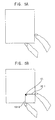
- FIGS. 5A through 5D are diagrams illustrating an example in which a click operation is performed in the electronic device of FIG. 1 .
- FIG. 6 is a diagram illustrating an example in which a click operation is determined as a right click operation or a left click operation of computer mouse devices in the electronic device of FIG. 1 .
- a click operation CK is performed in the electronic device 100 of FIG. 1 .
- an activation time e.g., a set or predetermined activation time
- a first pointer line 122-1 extended from a first touched point of the left side-surface touch sensor 140-11 or the right side-surface touch sensor 140-12, and a second pointer line 122-2 extended from a second touched point of the upper side-surface touch sensor 140-21 or the lower side-surface touch sensor 140-22 may be displayed on the front-surface touch screen 120.
- a pointer 121 may be displayed at a crossing point of the first pointer line 122-1 and the second pointer line 122-2. That is, when the user concurrently touches one of the left side-surface touch sensor 140-11 and the right side-surface touch sensor 140-12, and one of the upper side-surface touch sensor 140-21 and the lower side-surface touch sensor 140-22 for more than the activation time, the pointer 121, the first pointer line 122-1, and the second pointer line 122-2 may be displayed on the front-surface touch screen 120. For example, it is illustrated in FIGS.
- the first pointer line 122-1 extended from the first touched point of the right side-surface touch sensor 140-12 and the second pointer line 122-2 extended from the second touched point of the lower side-surface touch sensor 140-22 are displayed on the front-surface touch screen 120 when the right side-surface touch sensor 140-12 and the lower side-surface touch sensor 140-22 are concurrently touched by the user for more than the activation time.
- the pointer 121 is displayed at the crossing point of the first pointer line 122-1 and the second pointer line 122-2 when the right side-surface touch sensor 140-12 and the lower side-surface touch sensor 140-22 are concurrently touched by the user for more than the activation time.
- the pointer 121, the first pointer line 122-1, and the second pointer line 122-2 may be moved on the front-surface touch screen 120.
- the pointer 121, the first pointer line 122-1, and the second pointer line 122-2 may be moved in a drag direction.
- the user may move the first pointer line 122-1 extended from the first touched point of the left side-surface touch sensor 140-11 or the right side-surface touch sensor 140-12, and the second pointer line 122-2 extended from the second touched point of the upper side-surface touch sensor 140-21 or the lower side-surface touch sensor 140-22 by moving the first touched point of the left side-surface touch sensor 140-11 or the right side-surface touch sensor 140-12, and the second touched point of the upper side-surface touch sensor 140-21 or the lower side-surface touch sensor 140-22.
- the pointer 121 that is displayed at the crossing point of the first pointer line 122-1 and the second pointer line 122-2 may be moved on the front-surface touch screen 120.
- the user may place the pointer 121 at a desired location on the front-surface touch screen 120 by dragging a touched point of the respective side-surface touch sensors 140 while watching the pointer 121, the first pointer line 122-1, and the second pointer line 122-2 that are displayed on the front-surface touch screen 120.
- the pointer 121, the first pointer line 122-1, and the second pointer line 122-2 are moved as the first touched point of the right side-surface touch sensor 140-12 and the second touched point of the lower side-surface touch sensor 140-22 are moved.
- the processor 162 of the body 160 may perform a click operation CK on contents (e.g., icon, text, etc.) at which the pointer 121 points when the front-surface touch screen 120 is touched by the user (S160).
- contents e.g., icon, text, etc.
- the processor 162 of the body 160 may perform a first click operation on the contents when a first region IR of the front-surface touch screen 120 is touched by the user, where the first region IR is a region within a reference distance (e.g., a set or predetermined distance) from the pointer 121.
- the processor 162 of the body 160 may perform a second click operation on the contents when a second region OR of the front-surface touch screen 120 is touched by the user, where the second region is a region outside the reference distance from the pointer 121.
- the first click operation may correspond to a left click operation of a computer mouse device
- the second click operation may correspond to a right click operation of the computer mouse device.
- a way of performing the first click operation and the second click operation, a function of the first click operation and the second click operation, etc. may be determined in various ways.
- the first click operation may correspond to the right click operation of the computer mouse device
- the second click operation may correspond to the left click operation of the computer mouse device.
- the pointer 121, the first pointer line 122-1, and the second pointer line 122-2 may disappear from the front-surface touch screen 120 when a deactivation time (e.g., a set or predetermined deactivation time) elapses after the first touched point of the left side-surface touch sensor 140-11 or the right side-surface touch sensor 140-12, and the second touched point of the upper side-surface touch sensor 140-21 or the lower side-surface touch sensor 140-22 have been moved by the user.
- a deactivation time e.g., a set or predetermined deactivation time
- FIG. 7 is a flow chart illustrating a procedure in which a drag operation is performed in the electronic device of FIG. 1 .
- FIGS. 8A through 8D are diagrams illustrating an example in which a drag operation is performed in the electronic device of FIG. 1 .
- a drag operation is performed in the electronic device 100 of FIG. 1 .
- a starting point DS of the drag operation may be determined (S220) as the pointer 121, the first pointer line 122-1, and the second pointer line 122-2 that are displayed on the front-surface touch screen 120 are moved by the user. Subsequently, as illustrated in FIGS.
- touches on the side-surface touch sensors 140 may be released by the user (S240), and then one of the left side-surface touch sensor 140-11 and the right side-surface touch sensor 140-12, and one of the upper side-surface touch sensor 140-21 and the lower side-surface touch sensor 140-22 may be touched again by the user within a reactivation time (e.g., a set or predetermined reactivation time) (S260).
- a reactivation time e.g., a set or predetermined reactivation time
- a drag region 123 may be set (or determined) based on a moving distance of the first touched point of the left side-surface touch sensor 140-11 or the right side-surface touch sensor 140-12, and a moving distance of the second touched point of the upper side-surface touch sensor 140-21 or the lower side-surface touch sensor 140-22.
- the drag operation may be performed by moving the first touched point of the left side-surface touch sensor 140-11 or the right side-surface touch sensor 140-12, and the second touched point of the upper side-surface touch sensor 140-21 or the lower side-surface touch sensor 140-22.
- the drag operation is performed by moving the first touched point of the right side-surface touch sensor 140-12 and the second touched point of the lower side-surface touch sensor 140-22.
- FIG. 9 is a flow chart illustrating a procedure in which a region division operation is performed in the electronic device of FIG. 1 .
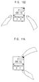
- FIGS. 10A through 10D are diagrams illustrating an example in which a region division operation is performed in the electronic device of FIG. 1 .
- FIGS. 11A through 11D are diagrams illustrating another example in which a region division operation is performed in the electronic device of FIG. 1 .
- FIGS. 9 through 11D it is illustrated that the region division operation is performed in the electronic device of FIG. 1 .
- an activation time e.g., a set or predetermined activation time
- a first division line 124 coupled between a first touched point of the left side-surface touch sensor 140-11 and a second touched point of the right side-surface touch sensor 140-12 may be displayed on the front-surface touch screen 120. Subsequently, as illustrated in FIG.
- the first division line 124 may be moved on the front-surface touch screen 120.
- a display region of the front-surface touch screen 120 may be divided into an upper display region and a lower display region by the first division line 124.
- the first division line 124 may disappear on the front-surface touch screen 120 when a deactivation time (e.g., a set or predetermined deactivation time) elapses after the first touched point of the left side-surface touch sensor 140-11 and the second touched point of the right side-surface touch sensor 140-12 have been moved.
- a deactivation time e.g., a set or predetermined deactivation time
- FIGS. 11A and 11B when the upper side-surface touch sensor 140-21 and the lower side-surface touch sensor 140-22 are concurrently touched by the user for more than the activation time (S320), a second division line 125 coupled between a third touched point of the upper side-surface touch sensor 140-21 and a fourth touched point of the lower side-surface touch sensor 140-22 may be displayed on the front-surface touch screen 120. Subsequently, as illustrated in FIG. 11C , as the third touched point of the upper side-surface touch sensor 140-21 and the fourth touched point of the lower side-surface touch sensor 140-22 are moved by the user (S340), the second division line 125 may be moved on the front-surface touch screen 120. Next, as illustrated in FIG.
- a display region of the front-surface touch screen 120 may be divided into a left display region and a right display region by the second division line 125.
- the second division line 125 may disappear on the front-surface touch screen 120 when the deactivation time elapses after the third touched point of the upper side-surface touch sensor 140-21 and the fourth touched point of the lower side-surface touch sensor 140-22 have been moved.
- FIG. 12 is a flow chart illustrating a procedure in which a region division operation is partially performed in the electronic device of FIG. 1 .
- FIGS. 13A through 13D are diagrams illustrating an example in which a region division operation is partially performed in the electronic device of FIG. 1 .
- FIGS. 12 through 13D it is illustrated that the region division operation is partially performed in the electronic device of FIG. 1 .
- a partial division line 126 may be displayed on the upper display region or the lower display region of the front-surface touch screen 120 when the upper side-surface touch sensor 140-21 or the lower side-surface touch sensor 140-22 is touched by the user for more than an activation time (e.g., a set or predetermined activation time) (S420).
- an activation time e.g., a set or predetermined activation time
- the partial division line 126 is displayed on the upper display region of the front-surface touch screen 120 when the upper side-surface touch sensor 140-21 is touched by the user for more than the activation time.
- the partial division line 126 may be moved, and thus the upper display region or the lower display region may be divided into a left display region and a right display region.
- the upper display region is divided into the left display region and the right display region by the partial division line 126.
- a left display region (or a right display region) may be divided into an upper display region and a lower display region.
- upper and lower display regions or left and right display regions may be simultaneously divided into left and right display regions (or upper and lower display regions).
- FIG. 14 is a flow chart illustrating a procedure in which a region adjustment operation is performed in the electronic device of FIG. 1 .
- FIGS. 15A through 15D are diagrams illustrating an example in which a region adjustment operation is performed in the electronic device of FIG. 1 .
- FIGS. 14 through 15D it is illustrated that the region adjustment operation is performed in the electronic device of FIG. 1 .
- a display region of the front-surface touch screen 120 is divided into an upper display region, a lower display region, a left display region, and a right display region
- a vertical division line 127 e.g., a left region -right region division line
- an activation time e.g., a set or predetermined activation time
- the left display region and the right display region may be relatively adjusted (e.g., an area of the left display region and an area of the right display region may be relatively changed) as a touched point of the upper side-surface touch sensor 140-21 and a touched point of the lower side-surface touch sensor 140-22 are moved by the user (S540).
- the region adjustment operation for the left display region and the right display region may be finished.
- a horizontal division line 127 (e.g., an upper region-lower region division line) may be displayed again on the front-surface touch screen 120 when the left side-surface touch sensor 140-11 and the right side-surface touch sensor 140-12 are concurrently touched by the user for more than the activation time.
- the upper display region and the lower display region may be relatively adjusted (e.g., an area of the upper display region and an area of the lower display region may be relatively changed) as a touched point of the left side-surface touch sensor 140-11 and a touched point of the right side-surface touch sensor 140-12 are moved by the user.
- the region adjustment operation for the upper display region and the lower display region may be finished.
- FIG. 16 is a flow chart illustrating a procedure in which a region adjustment operation is partially performed in the electronic device of FIG. 1 .
- FIGS. 17A through 17D are diagrams illustrating an example in which a region adjustment operation is partially performed in the electronic device of FIG. 1 .
- FIGS. 16 through 17D it is illustrated that the region adjustment operation is partially performed in the electronic device of FIG. 1 .
- a partial division line 128 may be displayed on the front-surface touch screen 120 when the left side-surface touch sensor 140-11, the right side-surface touch sensor 140-12, the upper side-surface touch sensor 140-21, or the lower side-surface touch sensor 140-22 is touched by the user for more than an activation time (e.g., a set or predetermined activation time) (S620).
- an activation time e.g., a set or predetermined activation time
- the region adjustment operation may be performed on each display region of the front-surface touch screen 120 (e.g., the upper display region, the lower display region, the left display region, or the right display region) as a touched point of the left side-surface touch sensor 140-11, the right side-surface touch sensor 140-12, the upper side-surface touch sensor 140-21, or the lower side-surface touch sensor 140-22 is moved by the user (S640). For example, it is illustrated in FIG.
- left and right display regions of the upper display region are relatively adjusted (e.g., an area of the left display region of the upper display region and an area of the right display region of the upper display region are relatively changed).
- FIG. 17D when a touch on the left side-surface touch sensor 140-11, the right side-surface touch sensor 140-12, the upper side-surface touch sensor 140-21, or the lower side-surface touch sensor 140-22 are released by the user (S660), the region adjustment operation for each display region (e.g., the upper display region, the lower display region, the left display region, or the right display region) may be finished.
- FIG. 18 is a flow chart illustrating a procedure in which a region movement operation is performed in the electronic device of FIG. 1 .
- FIGS. 19A through 19D are diagrams illustrating an example in which a region movement operation is performed in the electronic device of FIG. 1 .
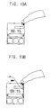
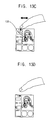
- a first division line 129-1 and a second division line 129-2 may be displayed again on the front-surface touch screen 120 when the left side-surface touch sensor 140-11 and the right side-surface touch sensor 140-12 are concurrently touched in a staggered manner by the user for more than an activation time (e.g., a set or predetermined activation time) (S720), or when the upper side-surface touch sensor 140-21 and the lower side-surface touch sensor 140-22 are concurrently touched in a staggered manner by the user for more than the activation time (S720).
- an activation time e.g., a set or predetermined activation time
- the display region of the front-surface touch screen 120 may include first through fourth display regions FA, SA, TA, and PA that are divided by the first division line 129-1 and the second division line 129-2.
- first through fourth display regions FA, SA, TA, and PA are divided by the first division line 129-1 and the second division line 129-2.
- FIGS. 19A and 19B it is illustrated in FIGS. 19A and 19B that the left side-surface touch sensor 140-11 and the right side-surface touch sensor 140-12 are concurrently touched in a staggered manner by the user for more than the activation time. Subsequently, as illustrated in FIG.
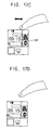
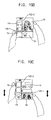
- the first through fourth display regions FA, SA, TA, and PA of the front-surface touch screen 120 may be rotated about a crossing point of the first division line 129-1 and the second division line 129-2 as a touched point of the left side-surface touch sensor 140-11 and a touched point of the right side-surface touch sensor 140-12 are moved by the user (S740), or as a touched point of the upper side-surface touch sensor 140-21 and a touched point of the lower side-surface touch sensor 140-22 are moved by the user (S740).
- FIG. 19C it is illustrated in FIG. 19C that the touched point of the left side-surface touch sensor 140-11 and the touched point of the right side-surface touch sensor 140-12 are moved by the user.
- FIG. 19D when touches on side-surface touch sensors 140 are released by the user (S760), the region movement operation for the first through fourth display regions FA, SA, TA, and PA may be finished.
- FIG. 20 is a flow chart illustrating a procedure in which a region zooming operation is performed in the electronic device of FIG. 1 .
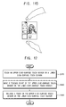
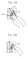
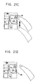
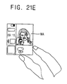
- FIGS. 21A through 21E are diagrams illustrating an example in which a region zooming operation is performed in the electronic device of FIG. 1 .
- FIGS. 20 through 21E it is illustrated that the region zooming operation is performed in the electronic device of FIG. 1 .
- a display region of the front-surface touch screen 120 is divided into a left display region, a right display region, an upper display region, and a lower display region
- a first division line 129-1 and a second division line 129-2 may be displayed again on the front-surface touch screen 120 when one of the left side-surface touch sensor 140-11 and the right side-surface touch sensor 140-12, and one of the upper side-surface touch sensor 140-21 and the lower side-surface touch sensor 140-22 are concurrently touched by the user for more than an activation time (e.g., a set or predetermined activation time) (S820).
- an activation time e.g., a set or predetermined activation time
- a target display region MA may be determined among divided display regions (e.g., the left display region, the right display region, the upper display region, and the lower display region) (S840) when one of the divided display regions (e.g., the target display region MA) is touched by the user.
- divided display regions e.g., the left display region, the right display region, the upper display region, and the lower display region
- the target display region MA may be zoomed-in or zoomed-out as a touched point of the left side-surface touch sensor 140-11, the right side-surface touch sensor 140-12, the upper side-surface touch sensor 140-21, or the lower side-surface touch sensor 140-22 is moved by the user (S860).
- a touched point of the right side-surface touch sensor 140-12 is moved by the user. Then, as illustrated in FIG.
- the region zooming operation for the target display region MA may be finished when one of the left side-surface touch sensor 140-11 and the right side-surface touch sensor 140-12, and one of the upper side-surface touch sensor 140-21 and the lower side-surface touch sensor 140-22 are concurrently touched by the user for more than a deactivation time (e.g., a set or predetermined deactivation time) (S880).
- a deactivation time e.g., a set or predetermined deactivation time
- the present inventive concept may be applied to any electronic devices that include a touch screen (e.g., a watch-shaped mobile device).
- a touch screen e.g., a watch-shaped mobile device
- the present inventive concept may be applied to a cellular phone, a smart phone, a smart pad, a personal digital assistant (PDA), a portable multimedia player (PMP), an MP3 player, a tablet PC, a laptop, a digital camera, a camcorder, a game console, etc.
Landscapes
- Engineering & Computer Science (AREA)
- Theoretical Computer Science (AREA)
- General Engineering & Computer Science (AREA)
- Physics & Mathematics (AREA)
- General Physics & Mathematics (AREA)
- Human Computer Interaction (AREA)
- Computer Hardware Design (AREA)
- User Interface Of Digital Computer (AREA)
- Position Input By Displaying (AREA)
Abstract
Description
- Example embodiments relate generally to an electronic device. More particularly, embodiments of the present inventive concept relate to an electronic device including a touch screen.
- Recently, electronic devices including a touch screen (e.g., a mobile device such as a cellular phone, a smart phone, a smart pad, etc.) are widely used. In addition, an interest in a watch-shaped mobile device (e.g., referred to as a smart watch) increases, where the smart watch interworks with the mobile device, or independently performs a function of the mobile device. However, since a user wears the watch-shaped mobile device on a wrist, the size of a front-surface touch screen included in the watch-shaped mobile device has limits, unlike the mobile device such as the cellular phone, the smart phone, the smart pad, etc. Generally, compared to a front-surface touch screen included in the mobile device such as the cellular phone, the smart phone, the smart pad, etc., the front-surface touch screen included in the watch-shaped mobile device has a relatively small size (e.g., about 3.302 cm). Thus, when a conventional method in which a user inputs a user-command by touching and/or dragging on the front-surface touch screen of the mobile device is employed in the watch-shaped mobile device, the user-command may not be accurately and precisely input to the mobile device. As a result, the user-command may be erroneously input to the mobile device.
- Some example embodiments provide an electronic device capable of allowing a user to accurately and precisely input a user-command to the electronic device although the electronic device includes a front-surface touch screen having a relatively small size.
- According to some example embodiments, an electronic device may include a front-surface touch screen; a plurality of side-surface touch sensors configured to receive a user-command; and a body including a processor for processing the user-command, wherein the body is combined with the front-surface touch screen and the side-surface touch sensors. Here, the user-command may include an operation in which at least one of the side-surface touch sensors is touched by a user for more than an activation time, and an operation in which a touched point of the at least one of the side-surface touch sensors is moved by the user.
- In example embodiments, the side-surface touch sensors may include a left side-surface touch sensor, a right side-surface touch sensor, an upper side-surface touch sensor, and a lower side-surface touch sensor with respect to a center of the body.
- In example embodiments, the electronic device may correspond to a watch-shaped mobile device that the user wears on a wrist.
- In example embodiments, a first pointer line extended from a first touched point of the left side-surface touch sensor or the right side-surface touch sensor, and a second pointer line extended from a second touched point of the upper side-surface touch sensor or the lower side-surface touch sensor may be displayed on the front-surface touch screen when one of the left side-surface touch sensor and the right side-surface touch sensor, and one of the upper side-surface touch sensor and the lower side-surface touch sensor are concurrently touched by the user for more than the activation time. In addition, a pointer may be displayed at a crossing point of the first pointer line and the second pointer line on the front-surface touch screen.
- In example embodiments, the pointer, the first pointer line, and the second pointer line may be moved on the front-surface touch screen as the first touched point and the second touched point are moved by the user. In addition, the pointer, the first pointer line, and the second pointer line may disappear from the front-surface touch screen when a deactivation time elapses after the first touched point and the second touched point have been moved by the user.
- In example embodiments, the processor may perform a click operation on contents at which the pointer points when the front-surface touch screen is touched by the user while the pointer, the first pointer line, and the second pointer line are displayed on the front-surface touch screen.
- In example embodiments, the processor may perform a first click operation on the contents when a first region of the front-surface touch screen is touched by the user while the pointer, the first pointer line, and the second pointer line are displayed on the front-surface touch screen, wherein the first region is a region within a reference distance from the pointer. In addition, the processor may perform a second click operation on the contents when a second region of the front-surface touch screen is touched by the user while the pointer, the first pointer line, and the second pointer line are displayed on the front-surface touch screen, wherein the second region is a region outside the reference distance from the pointer.
- In example embodiments, the first click operation may correspond to a left click operation of a computer mouse device, and the second click operation may correspond to a right click operation of the computer mouse device.
- In example embodiments, the processor may perform a drag operation on the contents when, the side-surface touch sensors are touched again by the user within a reactivation time after touches on the side-surface touch sensors are released by the user, and the first touched point and the second touched point are moved while the pointer, the first pointer line, and the second pointer line are displayed on the front-surface touch screen.
- In example embodiments, the reactivation time may be shorter than the activation time.
- In example embodiments, a first division line coupled between a first touched point of the left side-surface touch sensor and a second touched point of the right side-surface touch sensor may be displayed on the front-surface touch screen when the left side-surface touch sensor and the right side-surface touch sensor are concurrently touched by the user for more than the activation time.
- In example embodiments, a second division line coupled between a third touched point of the upper side-surface touch sensor and a fourth touched point of the lower side-surface touch sensor may be displayed on the front-surface touch screen when the upper side-surface touch sensor and the lower side-surface touch sensor are concurrently touched by the user for more than the activation time.
- In example embodiments, the first division line may be moved on the front-surface touch screen as the first touched point and the second touched point are moved by the user. In addition, the second division line may be moved on the front-surface touch screen as the third touched point and the fourth touched point are moved by the user.
- In example embodiments, a display region of the front-surface touch screen may be divided into an upper display region and a lower display region by the first division line, and may be divided into a left display region and a right display region by the second division line.
- In example embodiments, the first division line may disappear from the front-surface touch screen when a deactivation time elapses after the first touched point and the second touched point have been moved by the user. In addition, the second division line may disappear from the front-surface touch screen when the deactivation time elapses after the third touched point and the fourth touched point have been moved by the user.
- In example embodiments, the first division line may be displayed again on the front-surface touch screen when the left side-surface touch sensor and the right side-surface touch sensor are concurrently touched by the user for more than the activation time while the display region of the front-surface touch screen is divided into the upper display region and the lower display region. In addition, the upper display region and the lower display region may be relatively adjusted as the first touched point and the second touched point are moved by the user.
- In example embodiments, the second division line may be displayed again on the front-surface touch screen when the upper side-surface touch sensor and the lower side-surface touch sensor are concurrently touched by the user for more than the activation time while the display region of the front-surface touch screen is divided into the left display region and the right display region. In addition, the left display region and the right display region may be relatively adjusted as the third touched point and the fourth touched point are moved by the user.
- In example embodiments, the first division line or the second division line may be partially displayed again on the front-surface touch screen when the left side-surface touch sensor, the right side-surface touch sensor, the upper side-surface touch sensor, or the lower side-surface touch sensor is touched by the user for more than the activation time while the display region of the front-surface touch screen is divided into the left display region, the right display region, the upper display region, and the lower display region. In addition, the left and right display regions or the upper and lower display regions may be relatively adjusted as the first touched point, the second touched point, the third touched point, or the fourth touched point is moved by the user.
- In example embodiments, the first division line or the second division line may be displayed again on the front-surface touch screen when the left side-surface touch sensor and the right side-surface touch sensor are concurrently touched in a staggered manner by the user for more than the activation time, or when the upper side-surface touch sensor and the lower side-surface touch sensor are concurrently touched in a staggered manner by the user for more than the activation time while the display region of the front-surface touch screen is divided into the left display region, the right display region, the upper display region, and the lower display region. In addition, the left display region, the right display region, the upper display region, and the lower display region may be rotated about a crossing point of the first division line and the second division line as the first touched point, the second touched point, the third touched point, or the fourth touched point is moved by the user.
- In example embodiments, a target display region may be determined when one of the left display region, the right display region, the upper display region, and the lower display region is touched by the user after one of the left side-surface touch sensor and the right side-surface touch sensor, and one of the upper side-surface touch sensor and the lower side-surface touch sensor are concurrently touched by the user for more than the activation time while the display region of the front-surface touch screen is divided into the left display region, the right display region, the upper display region, and the lower display region. In addition, the target display region may be zoomed-in or zoomed-out as the first touched point, the second touched point, the third touched point, or the fourth touched point is moved by the user.
- Therefore, an electronic device according to example embodiments, where the electronic device includes a plurality of side-surface touch sensors for receiving a user-command, may allow a user to accurately and precisely input the user-command to the electronic device because the electronic device receives the user-command based on an operation in which at least one of the side-surface touch sensors is touched by the user for more than an activation time and an operation in which a touched point of respective side-surface touch sensors is dragged (e.g., moved) by the user.
- Illustrative, non-limiting example embodiments will be more clearly understood from the following detailed description taken in conjunction with the accompanying drawings.
-
FIG. 1 is a block diagram illustrating an electronic device according to example embodiments. -
FIG. 2 is a diagram illustrating an example in which the electronic device ofFIG. 1 is implemented as a watch-shaped mobile device. -
FIG. 3 is a diagram illustrating a front-surface touch screen, a plurality of side-surface touch sensors, and body included in the electronic device ofFIG. 1 . -
FIG. 4 is a flow chart illustrating a procedure in which a click operation is performed in the electronic device ofFIG. 1 . -
FIGS. 5A through 5D are diagrams illustrating an example in which a click operation is performed in the electronic device ofFIG. 1 . -
FIG. 6 is a diagram illustrating an example in which a click operation is determined as a right click operation or a left click operation of computer mouse devices in the electronic device ofFIG. 1 . -
FIG. 7 is a flow chart illustrating a procedure in which a drag operation is performed in the electronic device ofFIG. 1 . -
FIGS. 8A through 8D are diagrams illustrating an example in which a drag operation is performed in the electronic device ofFIG. 1 . -
FIG. 9 is a flow chart illustrating a procedure in which a region division operation is performed in the electronic device ofFIG. 1 . -
FIGS. 10A through 10D are diagrams illustrating an example in which a region division operation is performed in the electronic device ofFIG. 1 . -
FIGS. 11A through 11D are diagrams illustrating another example in which a region division operation is performed in the electronic device ofFIG. 1 . -
FIG. 12 is a flow chart illustrating a procedure in which a region division operation is partially performed in the electronic device ofFIG. 1 . -
FIGS. 13A through 13D are diagrams illustrating an example in which a region division operation is partially performed in the electronic device ofFIG. 1 . -
FIG. 14 is a flow chart illustrating a procedure in which a region adjustment operation is performed in the electronic device ofFIG. 1 . -
FIGS. 15A through 15D are diagrams illustrating an example in which a region adjustment operation is performed in the electronic device ofFIG. 1 . -
FIG. 16 is a flow chart illustrating a procedure in which a region adjustment operation is partially performed in the electronic device ofFIG. 1 . -
FIGS. 17A through 17D are diagrams illustrating an example in which a region adjustment operation is partially performed in the electronic device ofFIG. 1 . -
FIG. 18 is a flow chart illustrating a procedure in which a region movement operation is performed in the electronic device ofFIG. 1 . -
FIGS. 19A through 19D are diagrams illustrating an example in which a region movement operation is performed in the electronic device ofFIG. 1 . -
FIG. 20 is a flow chart illustrating a procedure in which a region zooming operation is performed in the electronic device ofFIG. 1 . -
FIGS. 21A through 21E are diagrams illustrating an example in which a region zooming operation is performed in the electronic device ofFIG. 1 . - Hereinafter, embodiments of the present inventive concept will be explained in more detail with reference to the accompanying drawings.
-
FIG. 1 is a block diagram illustrating an electronic device according to example embodiments.FIG. 2 is a diagram illustrating an example in which the electronic device ofFIG. 1 is implemented as a watch-shaped mobile device.FIG. 3 is a diagram illustrating a front-surface touch screen, a plurality of side-surface touch sensors, and a body included in the electronic device ofFIG. 1 . - Referring to
FIGS. 1 through 3 , theelectronic device 100 may include a front-surface touch screen 120, a plurality of side-surface touch sensors 140, and abody 160. The front-surface touch screen 120 and the side-surface touch sensors 140 may be combined with thebody 160. In some example embodiments, as illustrated inFIG. 2 , theelectronic device 100 may be a watch-shaped mobile device that a user wears on the wrist (e.g., referred to as a smart watch). - The front-
surface touch screen 120 may perform a display function and a touch sensor function. Here, the front-surface touch screen 120 may include a display panel for performing the display function and a touch sensing panel for performing the touch sensor function. In some example embodiments, the front-surface touch screen 120 may be a flexible touch screen. When theelectronic device 100 corresponds to the watch-shaped mobile device that interworks with a mobile device such as a cellular phone, a smart phone, a smart pad, etc., or independently performs a function of the mobile device, the front-surface touch screen 120 included in theelectronic device 100 may have a relatively small size (e.g., about 3.302 cm) compared to a front-surface touch screen included in the mobile device such as the cellular phone, the smart phone, the smart pad, etc., because the user wears the electronic device 100 (e.g., watch-shaped mobile device) on the wrist. Thus, theelectronic device 100 may not depend on a conventional (comparable) method in which a user inputs a user-command by touching and/or dragging on a front-surface touch screen. That is, theelectronic device 100 may receive the user-command by mainly using (or utilizing) the side-surface touch sensors 140. Hereinafter, it will be described that theelectronic device 100 receives the user-command by using (or utilizing) the side-surface touch sensors 140. However, the present inventive concept does not exclude the conventional method in which theelectronic device 100 receives the user-command by using (or utilizing) the front-surface touch screen 120. For example, theelectronic device 100 may receive the user-command by using (or utilizing) the front-surface touch screen 120 as well as by using (or utilizing) the side-surface touch sensors 140. - As described above, the side-
surface touch sensors 140 included in theelectronic device 100 may receive the user-command. For example, as illustrated inFIG. 3 , the side-surface touch sensors 140 may include a left side-surface touch sensor 140-11, a right side-surface touch sensor 140-12, an upper side-surface touch sensor 140-21, and a lower side-surface touch sensor 140-22 with respect to a center of thebody 160. In some example embodiments, the side-surface touch sensors 140 may include one of the left side-surface touch sensor 140-11 and the right side-surface touch sensor 140-12, and one of the upper side-surface touch sensor 140-21 and the lower side-surface touch sensor 140-22. In other words, the side-surface touch sensors 140 may include one or more of the left side-surface touch sensor 140-11, the right side-surface touch sensor 140-12, the upper side-surface touch sensor 140-21, and the lower side-surface touch sensor 140-22 with respect to a center of thebody 160. The user-command may include an operation in which at least one of the side-surface touch sensors 140 is touched by the user for more than an activation time (e.g., a set or predetermined activation time), and an operation in which a touched point of respective side-surface touch sensors 140 is dragged (e.g., moved) by the user. That is, the user may input the user-command to theelectronic device 100 by touching at least one of the side-surface touch sensors 140 for more than the activation time (e.g., the set or predetermined activation time at a respective touched point), and by dragging (e.g., moving) the touched point of the respective side-surface touch sensors 140. Here, the user-command may be processed by aprocessor 162 included in thebody 160. - In an example embodiment, when one of the left side-surface touch sensor 140-11 and the right side-surface touch sensor 140-12, and one of the upper side-surface touch sensor 140-21 and the lower side-surface touch sensor 140-22 are concurrently touched by the user for more than the activation time, a first pointer line extended from a first touched point of the left side-surface touch sensor 140-11 or the right side-surface touch sensor 140-12, and a second pointer line extended from a second touched point of the upper side-surface touch sensor 140-21 or the lower side-surface touch sensor 140-22 may be displayed on the front-
surface touch screen 120. Here, a pointer may be displayed at a crossing point of the first pointer line and the second pointer line. For example, when the right side-surface touch sensor 140-12 and the lower side-surface touch sensor 140-22 are concurrently touched by the user for more than the activation time, the first pointer line extended from the first touched point of the right side-surface touch sensor 140-12 and the second pointer line extended from the second touched point of the lower side-surface touch sensor 140-22 may be displayed on the front-surface touch screen 120. In addition, the pointer may be displayed at the crossing point of the first pointer line and the second pointer line. Further, the first pointer line and the second pointer line may be perpendicular to each other. However, the present inventive concept is not limited to the above example. That is, the right side-surface touch sensor 140-12 and the upper side-surface touch sensor 140-21 may be concurrently touched by the user, the left side-surface touch sensor 140-11 and the lower side-surface touch sensor 140-22 may be concurrently touched by the user, or the left side-surface touch sensor 140-11 and the upper side-surface touch sensor 140-21 may be concurrently touched by the user. - As described above, when one of the left side-surface touch sensor 140-11 and the right side-surface touch sensor 140-12, and one of the upper side-surface touch sensor 140-21 and the lower side-surface touch sensor 140-22 are touched by the user for more than the activation time, the pointer, the first pointer line, and the second pointer line may be displayed on the front-
surface touch screen 120. Subsequently, as the first touched point of the left side-surface touch sensor 140-11 or the right side-surface touch sensor 140-12, and the second touched point of the upper side-surface touch sensor 140-21 or the lower side-surface touch sensor 140-22 are dragged (e.g., moved) by the user, the first pointer line extended from the first touched point of the left side-surface touch sensor 140-11 or the right side-surface touch sensor 140-12, the second pointer line extended from the second touched point of the upper side-surface touch sensor 140-21 or the lower side-surface touch sensor 140-22, and the pointer displayed at the crossing point of the first pointer line and the second pointer line may be moved. Hence, the user may move a touched point of respective side-surface touch sensors 140 by dragging the touched point of respective side-surface touch sensors 140 (e.g., by dragging the first touched point of the left side-surface touch sensor 140-11 or the right side-surface touch sensor 140-12, and the second touched point of the upper side-surface touch sensor 140-21 or the lower side-surface touch sensor 140-22) while watching the pointer, the first pointer line, and the second pointer line that are displayed on the front-surface touch screen 120. - While the pointer, the first pointer line, and the second pointer line are displayed on the front-
surface touch screen 120, theprocessor 162 of thebody 160 may perform a click operation on contents (e.g., icon, text, etc.) at which the pointer points when the front-surface touch screen 120 is touched by the user. For example, while the pointer, the first pointer line, and the second pointer line are displayed on the front-surface touch screen 120, theprocessor 162 of thebody 160 may perform a first click operation on the contents when a first region of the front-surface touch screen 120 is touched by the user, where the first region is a region within a reference distance (e.g., a set or predetermined distance) from the pointer. On the other hand, while the pointer, the first pointer line, and the second pointer line are displayed on the front-surface touch screen 120, theprocessor 162 of thebody 160 may perform a second click operation on the contents when a second region of the front-surface touch screen 120 is touched by the user, where the second region is a region outside the reference distance (e.g., the set or predetermined distance) from the pointer. For example, the first click operation may correspond to a left click operation of a computer mouse device, and the second click operation may correspond to a right click operation of the computer mouse device. However, since these are examples, a way of performing the first click operation and the second click operation, a function of the first click operation and the second click operation, etc. may be determined in various ways. For example, the first click operation may correspond to the right click operation of the computer mouse device, and the second click operation may correspond to the left click operation of the computer mouse device. In some example embodiments, the pointer, the first pointer line, and the second pointer line may not be displayed on the front-surface touch screen 120 when a deactivation time (e.g., a set or predetermined deactivation time) elapses after the first touched point of the left side-surface touch sensor 140-11 or the right side-surface touch sensor 140-12, and the second touched point of the upper side-surface touch sensor 140-21 or the lower side-surface touch sensor 140-22 have been moved by the user. In other words, the pointer, the first pointer line, and the second pointer line may disappear from the front-surface touch screen 120. - In another example embodiment, while the pointer, the first pointer line, and the second pointer line are displayed on the front-
surface touch screen 120, touches on the side-surface touch sensors 140 may be released by the user, and then one of the left side-surface touch sensor 140-11 and the right side-surface touch sensor 140-12, and one of the upper side-surface touch sensor 140-21 and the lower side-surface touch sensor 140-22 may be touched again by the user within a reactivation time (e.g., a set or predetermined reactivation time). Subsequently, when the first touched point of the left side-surface touch sensor 140-11 or the right side-surface touch sensor 140-12, and the second touched point of the upper side-surface touch sensor 140-21 or the lower side-surface touch sensor 140-22 are moved by the user, theprocessor 162 of thebody 160 may set (or, determine) a drag region based on a moving distance of the first touched point of the left side-surface touch sensor 140-11 or the right side-surface touch sensor 140-12, and a moving distance of the second touched point of the upper side-surface touch sensor 140-21 or the lower side-surface touch sensor 140-22. That is, theprocessor 162 of thebody 160 may perform a drag operation on the contents. For example, the drag region may be a quadrangular region, where one side of the quadrangular region corresponds to the moving distance of the first touched point of the left side-surface touch sensor 140-11 or the right side-surface touch sensor 140-12, and another side of the quadrangular region corresponds to the moving distance of the second touched point of the upper side-surface touch sensor 140-21 or the lower side-surface touch sensor 140-22. In some example embodiments, the reactivation time (e.g., a set or predetermined reactivation time) may be set to be shorter than the activation time. In other example embodiments, the reactivation time may be set to be longer than the activation time, or to be equal to the activation time. - In still another example embodiment, when the left side-surface touch sensor 140-11 and the right side-surface touch sensor 140-12 are concurrently touched by the user for more than the activation time, a first division line coupled between a first touched point of the left side-surface touch sensor 140-11 and a second touched point of the right side-surface touch sensor 140-12 may be displayed on the front-
surface touch screen 120. In addition, when the upper side-surface touch sensor 140-21 and the lower side-surface touch sensor 140-22 are concurrently touched by the user for more than the activation time, a second division line coupled between a third touched point of the upper side-surface touch sensor 140-21 and a fourth touched point of the lower side-surface touch sensor 140-22 may be displayed on the front-surface touch screen 120. Subsequently, as the first touched point of the left side-surface touch sensor 140-11 and the second touched point of the right side-surface touch sensor 140-12 are moved by the user, the first division line may be moved on the front-surface touch screen 120. Similarly, as the third touched point of the upper side-surface touch sensor 140-21 and the fourth touched point of the lower side-surface touch sensor 140-22 are moved by the user, the second division line may be moved on the front-surface touch screen 120. Here, a display region of the front-surface touch screen 120 may be divided into an upper display region and a lower display region by the first division line, and may be divided into a left display region and a right display region by the second division line. After the first touched point of the left side-surface touch sensor 140-11 and the second touched point of the right side-surface touch sensor 140-12 have been moved, the first division line may not be displayed on the front-surface touch screen 120 when a deactivation time (e.g., a set or predetermined deactivation time) elapses. That is, the first division line may disappear from the front-surface touch screen 120. Similarly, after the third touched point of the upper side-surface touch sensor 140-21 and the fourth touched point of the lower side-surface touch sensor 140-22 have been moved, the second division line may not be displayed on the front-surface touch screen 120 when the deactivation time elapses. That is, the second division line may disappear from the front-surface touch screen 120. - In still another example embodiment, while a display region of the front-
surface touch screen 120 is divided into an upper display region and a lower display region, a first division line may be displayed again on the front-surface touch screen 120 when the left side-surface touch sensor 140-11 and the right side-surface touch sensor 140-12 are concurrently touched by the user for more than an activation time (e.g., a set or predetermined activation time). Subsequently, as a first touched point of the left side-surface touch sensor 140-11 and a second touched point of the right side-surface touch sensor 140-12 are moved by the user, the upper display region and the lower display region may be relatively adjusted (e.g., an area of the upper display region and an area of the lower display region may be relatively changed). Similarly, while the display region of the front-surface touch screen 120 is divided into a left display region and a right display region, a second division line may be displayed again on the front-surface touch screen 120 when the upper side-surface touch sensor 140-21 and the lower side-surface touch sensor 140-22 are concurrently touched by the user for more than the activation time. Subsequently, as a third touched point of the upper side-surface touch sensor 140-21 and a fourth touched point of the lower side-surface touch sensor 140-22 are moved by the user, the left display region and the right display region may be relatively adjusted (e.g., an area of the left display region and an area of the right display region may be relatively changed). In addition, while the display region of the front-surface touch screen 120 is divided into the left display region, the right display region, the upper display region, and the lower display region, the first division line or the second division line may be partially displayed again on the front-surface touch screen 120 when the left side-surface touch sensor 140-11, the right side-surface touch sensor 140-12, the upper side-surface touch sensor 140-21, or the lower side-surface touch sensor 140-22 is touched by the user for more than the activation time. Subsequently, as the first touched point of the left side-surface touch sensor 140-11, the second touched point of the right side-surface touch sensor 140-12, the third touched point of the upper side-surface touch sensor 140-21, or the fourth touched point of the lower side-surface touch sensor 140-22 is moved by the user, the left and right display regions or the upper and lower display regions may be relatively adjusted (e.g., an area of the left display region and an area of the right display region may be relatively changed, or an area of the upper display region and an area of the lower display region may be relatively changed). - In still another example embodiment, while a display region of the front-
surface touch screen 120 is divided into a left display region, a right display region, an upper display region, and a lower display region, a first division line and a second division line may be displayed again on the front-surface touch screen 120 when the left side-surface touch sensor 140-11 and the right side-surface touch sensor 140-12 are concurrently touched in a staggered manner by the user for more than an activation time (e.g., a set or predetermined activation time), or when the upper side-surface touch sensor 140-21 and the lower side-surface touch sensor 140-22 are concurrently touched in a staggered manner by the user for more than the activation time. For example, when the upper side-surface touch sensor 140-21 and the lower side-surface touch sensor 140-22 are concurrently touched in a staggered manner by the user for more than the activation time, the first division line and the second division line may be displayed again on the front-surface touch screen 120. Subsequently, as a first touched point of the left side-surface touch sensor 140-11, a second touched point of the right side-surface touch sensor 140-12, a third touched point of the upper side-surface touch sensor 140-21, or a fourth touched point of the lower side-surface touch sensor 140-22 is moved by the user, divided display regions (e.g., the left display region, the right display region, the upper display region, and the lower display region) of the front-surface touch screen 120 may be rotated about a crossing point of the first division line and the second division line. - In still another example embodiment, while a display region of the front-
surface touch screen 120 is divided into a left display region, a right display region, an upper display region, and a lower display region, a first division line and a second division line may be displayed again on the front-surface touch screen 120 when one of the left side-surface touch sensor 140-11 and the right side-surface touch sensor 140-12, and one of the upper side-surface touch sensor 140-21 and the lower side-surface touch sensor 140-22 are concurrently touched by the user for more than an activation time (e.g., a set or predetermined activation time). For example, when the right side-surface touch sensor 140-12 and the lower side-surface touch sensor 140-22 are concurrently touched by the user for more than the activation time, the first division line and the second division line may be displayed again on the front-surface touch screen 120. Subsequently, the user may determine a target display region among divided display regions (e.g., the left display region, the right display region, the upper display region, and the lower display region) by touching one of the divided display regions. Thus, as a first touched point of the left side-surface touch sensor 140-11, a second touched point of the right side-surface touch sensor 140-12, a third touched point of the upper side-surface touch sensor 140-21, or a fourth touched point of the lower side-surface touch sensor 140-22 is moved by the user, the target display region may be zoomed-in or zoomed-out. - The body may be combined with the front-
surface touch screen 120 and the side-surface touch sensors 140. As described above, since the front-surface touch screen 120 includes the display panel and the touch sensing panel, thebody 160 may include at least one controller for controlling the display panel and the touch sensing panel (e.g., a display controller and a touch sensing controller). Here, the controller may control the display function and the touch sensor function of the front-surface touch screen 120. In addition, thebody 160 may include theprocessor 162 that processes the user-command input through the side-surface touch sensors 140. In some example embodiments, thebody 160 may receive the user-command through the front-surface touch screen 120 as well as the side-surface touch sensors 140. Theprocessor 160 may control an overall operation of theelectronic device 100 by performing specific calculations and/or specific tasks. For example, theprocessor 160 may be a micro-processor, a central processing unit (CPU), etc. In addition, thebody 160 may further include sensors, memory devices, storage devices, function devices, etc. The sensors may perform various sensing operations of theelectronic device 100. For example, the sensors may include a gyro sensor that measures a rotating angular speed, an acceleration sensor that measures a speed and a momentum, a geomagnetic field sensor that acts as a compass, a barometer sensor that measures an altitude, a grip sensor that determines whether theelectronic device 100 is gripped by the user, a gesture-proximity-illumination sensor that performs various operations such as a motion recognition, a proximity detection, an illumination measurement, etc., and/or a temperature-humidity sensor that measures a temperature and a humidity. However, the kinds of the sensors included in theelectronic device 100 are not limited thereto. - The memory devices may store data for operations of the
electronic device 100. For example, the memory devices may include a volatile semiconductor memory device such as a dynamic random access memory (DRAM) device, a static random access memory (SRAM) device, a mobile DRAM device, etc., and/or a non-volatile semiconductor memory device such as an erasable programmable read-only memory (EPROM) device, an electrically erasable programmable read-only memory (EEPROM) device, a flash memory device, a phase change random access memory (PRAM) device, a resistance random access memory (RRAM) device, a nano floating gate memory (NFGM) device, a polymer random access memory (PoRAM) device, a magnetic random access memory (MRAM) device, a ferroelectric random access memory (FRAM) device, etc. The storage devices may include a solid state drive (SSD) device, a hard disk drive (HDD) device, a CD-ROM device, etc. The function devices may perform various functions of theelectronic device 100. For example, the function devices may include a camera device that performs a camera function, a communication device that performs a communication function (e.g., one or more of code division multiple access (CDMA) module, long term evolution (LTE) module, radio frequency (RF) module, ultra wideband (UWB) module, wireless local area network (WLAN) module, worldwide interoperability for microwave access (WIMAX) module, etc.), a global positioning system (GPS) device, a microphone (MIC) device, a speaker device, etc. However, the kinds of the function devices included in theelectronic device 100 are not limited thereto. - As described above, the
electronic device 100 may include the side-surface touch sensors 140 for receiving the user-command. As such, theelectronic device 100 may allow the user to accurately and precisely input the user-command to theelectronic device 100 because theelectronic device 100 receives the user-command based on an operation in which at least one of the side-surface touch sensors 140 is touched by the user for more than the activation time and an operation in which the touched point of respective side-surface touch sensors 140 is dragged (e.g., moved) by the user. In brief, theelectronic device 100 employs a new user interface, so that the user may accurately and precisely input the user-command to theelectronic device 100. Although it is described above that theelectronic device 100 is implemented as the watch-shaped mobile device (e.g., referred to as the smart watch), the kinds of theelectronic device 100 are not limited thereto. For example, theelectronic device 100 may be implemented as a cellular phone, a smart phone, a smart pad, a personal digital assistant (PDA), a portable multimedia player (PMP), an MP3 player, a tablet PC, a laptop, a digital camera, a camcorder, a game console, etc. In addition, although various example embodiments in which the user-command is input to theelectronic device 100 are described above, the user-command may be input to theelectronic device 100 in various ways without materially departing from the novel teachings and features of the present inventive concept. -
FIG. 4 is a flow chart illustrating a procedure in which a click operation is performed in the electronic device ofFIG. 1 .FIGS. 5A through 5D are diagrams illustrating an example in which a click operation is performed in the electronic device ofFIG. 1 .FIG. 6 is a diagram illustrating an example in which a click operation is determined as a right click operation or a left click operation of computer mouse devices in the electronic device ofFIG. 1 . - Referring to
FIGS. 4 through 6 , it is illustrated that a click operation CK is performed in theelectronic device 100 ofFIG. 1 . For example, as illustrated inFIGS. 5A and 5B , when one of the left side-surface touch sensor 140-11 and the right side-surface touch sensor 140-12, and one of the upper side-surface touch sensor 140-21 and the lower side-surface touch sensor 140-22 are concurrently touched by a user for more than an activation time (e.g., a set or predetermined activation time) (S120), a first pointer line 122-1 extended from a first touched point of the left side-surface touch sensor 140-11 or the right side-surface touch sensor 140-12, and a second pointer line 122-2 extended from a second touched point of the upper side-surface touch sensor 140-21 or the lower side-surface touch sensor 140-22 may be displayed on the front-surface touch screen 120. Here, apointer 121 may be displayed at a crossing point of the first pointer line 122-1 and the second pointer line 122-2. That is, when the user concurrently touches one of the left side-surface touch sensor 140-11 and the right side-surface touch sensor 140-12, and one of the upper side-surface touch sensor 140-21 and the lower side-surface touch sensor 140-22 for more than the activation time, thepointer 121, the first pointer line 122-1, and the second pointer line 122-2 may be displayed on the front-surface touch screen 120. For example, it is illustrated inFIGS. 5A and 5B that the first pointer line 122-1 extended from the first touched point of the right side-surface touch sensor 140-12 and the second pointer line 122-2 extended from the second touched point of the lower side-surface touch sensor 140-22 are displayed on the front-surface touch screen 120 when the right side-surface touch sensor 140-12 and the lower side-surface touch sensor 140-22 are concurrently touched by the user for more than the activation time. In addition, it is illustrated that thepointer 121 is displayed at the crossing point of the first pointer line 122-1 and the second pointer line 122-2 when the right side-surface touch sensor 140-12 and the lower side-surface touch sensor 140-22 are concurrently touched by the user for more than the activation time. - Subsequently, as illustrated in
FIG. 5C , when the first touched point of the left side-surface touch sensor 140-11 or the right side-surface touch sensor 140-12, and the second touched point of the upper side-surface touch sensor 140-21 or the lower side-surface touch sensor 140-22 are dragged (e.g., moved) by the user (S140), thepointer 121, the first pointer line 122-1, and the second pointer line 122-2 may be moved on the front-surface touch screen 120. Here, thepointer 121, the first pointer line 122-1, and the second pointer line 122-2 may be moved in a drag direction. That is, the user may move the first pointer line 122-1 extended from the first touched point of the left side-surface touch sensor 140-11 or the right side-surface touch sensor 140-12, and the second pointer line 122-2 extended from the second touched point of the upper side-surface touch sensor 140-21 or the lower side-surface touch sensor 140-22 by moving the first touched point of the left side-surface touch sensor 140-11 or the right side-surface touch sensor 140-12, and the second touched point of the upper side-surface touch sensor 140-21 or the lower side-surface touch sensor 140-22. As a result, thepointer 121 that is displayed at the crossing point of the first pointer line 122-1 and the second pointer line 122-2 may be moved on the front-surface touch screen 120. In brief, the user may place thepointer 121 at a desired location on the front-surface touch screen 120 by dragging a touched point of the respective side-surface touch sensors 140 while watching thepointer 121, the first pointer line 122-1, and the second pointer line 122-2 that are displayed on the front-surface touch screen 120. For example, it is illustrated inFIG. 5C that thepointer 121, the first pointer line 122-1, and the second pointer line 122-2 are moved as the first touched point of the right side-surface touch sensor 140-12 and the second touched point of the lower side-surface touch sensor 140-22 are moved. - Next, as illustrated in
FIG. 5D , while thepointer 121, the first pointer line 122-1, and the second pointer line 122-2 are displayed on the front-surface touch screen 120, theprocessor 162 of thebody 160 may perform a click operation CK on contents (e.g., icon, text, etc.) at which thepointer 121 points when the front-surface touch screen 120 is touched by the user (S160). Here, as illustrated inFIG. 6 , theprocessor 162 of thebody 160 may perform a first click operation on the contents when a first region IR of the front-surface touch screen 120 is touched by the user, where the first region IR is a region within a reference distance (e.g., a set or predetermined distance) from thepointer 121. On the other hand, as illustrated inFIG. 6 , theprocessor 162 of thebody 160 may perform a second click operation on the contents when a second region OR of the front-surface touch screen 120 is touched by the user, where the second region is a region outside the reference distance from thepointer 121. For example, the first click operation may correspond to a left click operation of a computer mouse device, and the second click operation may correspond to a right click operation of the computer mouse device. However, since these are examples, a way of performing the first click operation and the second click operation, a function of the first click operation and the second click operation, etc. may be determined in various ways. For example, the first click operation may correspond to the right click operation of the computer mouse device, and the second click operation may correspond to the left click operation of the computer mouse device. In some example embodiments, thepointer 121, the first pointer line 122-1, and the second pointer line 122-2 may disappear from the front-surface touch screen 120 when a deactivation time (e.g., a set or predetermined deactivation time) elapses after the first touched point of the left side-surface touch sensor 140-11 or the right side-surface touch sensor 140-12, and the second touched point of the upper side-surface touch sensor 140-21 or the lower side-surface touch sensor 140-22 have been moved by the user. As a result, a pointer movement operation for the click operation CK may be finished. -
FIG. 7 is a flow chart illustrating a procedure in which a drag operation is performed in the electronic device ofFIG. 1 .FIGS. 8A through 8D are diagrams illustrating an example in which a drag operation is performed in the electronic device ofFIG. 1 . - Referring to
FIGS. 7 through 8D , it is illustrated that a drag operation is performed in theelectronic device 100 ofFIG. 1 . For example, as illustrated inFIGS. 8A and 8B , a starting point DS of the drag operation may be determined (S220) as thepointer 121, the first pointer line 122-1, and the second pointer line 122-2 that are displayed on the front-surface touch screen 120 are moved by the user. Subsequently, as illustrated inFIGS. 8B and8C , touches on the side-surface touch sensors 140 may be released by the user (S240), and then one of the left side-surface touch sensor 140-11 and the right side-surface touch sensor 140-12, and one of the upper side-surface touch sensor 140-21 and the lower side-surface touch sensor 140-22 may be touched again by the user within a reactivation time (e.g., a set or predetermined reactivation time) (S260). Next, as illustrated inFIG. 8D , when a first touched point of the left side-surface touch sensor 140-11 or the right side-surface touch sensor 140-12, and a second touched point of the upper side-surface touch sensor 140-21 or the lower side-surface touch sensor 140-22 are moved by the user (S280), adrag region 123 may be set (or determined) based on a moving distance of the first touched point of the left side-surface touch sensor 140-11 or the right side-surface touch sensor 140-12, and a moving distance of the second touched point of the upper side-surface touch sensor 140-21 or the lower side-surface touch sensor 140-22. That is, the drag operation may be performed by moving the first touched point of the left side-surface touch sensor 140-11 or the right side-surface touch sensor 140-12, and the second touched point of the upper side-surface touch sensor 140-21 or the lower side-surface touch sensor 140-22. For example, it is illustrated inFIG. 8D that the drag operation is performed by moving the first touched point of the right side-surface touch sensor 140-12 and the second touched point of the lower side-surface touch sensor 140-22. -
FIG. 9 is a flow chart illustrating a procedure in which a region division operation is performed in the electronic device ofFIG. 1 .FIGS. 10A through 10D are diagrams illustrating an example in which a region division operation is performed in the electronic device ofFIG. 1 .FIGS. 11A through 11D are diagrams illustrating another example in which a region division operation is performed in the electronic device ofFIG. 1 . - Referring to
FIGS. 9 through 11D , it is illustrated that the region division operation is performed in the electronic device ofFIG. 1 . As illustrated inFIGS. 10A and10B , when the left side-surface touch sensor 140-11 and the right side-surface touch sensor 140-12 are concurrently touched by the user for more than an activation time (e.g., a set or predetermined activation time) (S320), afirst division line 124 coupled between a first touched point of the left side-surface touch sensor 140-11 and a second touched point of the right side-surface touch sensor 140-12 may be displayed on the front-surface touch screen 120. Subsequently, as illustrated inFIG. 10C , as the first touched point of the left side-surface touch sensor 140-11 and the second touched point of the right side-surface touch sensor 140-12 are moved by the user (S340), thefirst division line 124 may be moved on the front-surface touch screen 120. Next, as illustrated inFIG. 10D , when touches on the left side-surface touch sensor 140-11 and the right side-surface touch sensor 140-12 are released by the user (S360), a display region of the front-surface touch screen 120 may be divided into an upper display region and a lower display region by thefirst division line 124. In some example embodiments, thefirst division line 124 may disappear on the front-surface touch screen 120 when a deactivation time (e.g., a set or predetermined deactivation time) elapses after the first touched point of the left side-surface touch sensor 140-11 and the second touched point of the right side-surface touch sensor 140-12 have been moved. - Similarly, as illustrated in
FIGS. 11A and 11B , when the upper side-surface touch sensor 140-21 and the lower side-surface touch sensor 140-22 are concurrently touched by the user for more than the activation time (S320), asecond division line 125 coupled between a third touched point of the upper side-surface touch sensor 140-21 and a fourth touched point of the lower side-surface touch sensor 140-22 may be displayed on the front-surface touch screen 120. Subsequently, as illustrated inFIG. 11C , as the third touched point of the upper side-surface touch sensor 140-21 and the fourth touched point of the lower side-surface touch sensor 140-22 are moved by the user (S340), thesecond division line 125 may be moved on the front-surface touch screen 120. Next, as illustrated inFIG. 11D , when touches on the upper side-surface touch sensor 140-21 and the lower side-surface touch sensor 140-22 are released by the user (S360), a display region of the front-surface touch screen 120 may be divided into a left display region and a right display region by thesecond division line 125. In some example embodiments, thesecond division line 125 may disappear on the front-surface touch screen 120 when the deactivation time elapses after the third touched point of the upper side-surface touch sensor 140-21 and the fourth touched point of the lower side-surface touch sensor 140-22 have been moved. -
FIG. 12 is a flow chart illustrating a procedure in which a region division operation is partially performed in the electronic device ofFIG. 1 .FIGS. 13A through 13D are diagrams illustrating an example in which a region division operation is partially performed in the electronic device ofFIG. 1 . - Referring to
FIGS. 12 through 13D , it is illustrated that the region division operation is partially performed in the electronic device ofFIG. 1 . For example, as illustrated inFIGS. 13A and 13B , while a display region of the front-surface touch screen 120 is divided into an upper display region and a lower display region, apartial division line 126 may be displayed on the upper display region or the lower display region of the front-surface touch screen 120 when the upper side-surface touch sensor 140-21 or the lower side-surface touch sensor 140-22 is touched by the user for more than an activation time (e.g., a set or predetermined activation time) (S420). For example, it is illustrated inFIGS. 13A and 13B that thepartial division line 126 is displayed on the upper display region of the front-surface touch screen 120 when the upper side-surface touch sensor 140-21 is touched by the user for more than the activation time. Subsequently, as illustrated inFIG. 13C , as a touched point of the upper side-surface touch sensor 140-21 or the lower side-surface touch sensor 140-22 is moved by the user (S440), thepartial division line 126 may be moved, and thus the upper display region or the lower display region may be divided into a left display region and a right display region. For example, it is illustrated inFIG. 13C that the upper display region is divided into the left display region and the right display region by thepartial division line 126. Next, as illustrated inFIG. 13D , when a touch on the upper side-surface touch sensor 140-21 or the lower side-surface touch sensor 140-22 is released by the user (S460), the region division operation for the upper display region or the lower display region may be finished. However, the present inventive concept is not limited thereto. For example, a left display region (or a right display region) may be divided into an upper display region and a lower display region. In addition, upper and lower display regions (or left and right display regions) may be simultaneously divided into left and right display regions (or upper and lower display regions). -
FIG. 14 is a flow chart illustrating a procedure in which a region adjustment operation is performed in the electronic device ofFIG. 1 .FIGS. 15A through 15D are diagrams illustrating an example in which a region adjustment operation is performed in the electronic device ofFIG. 1 . - Referring to
FIGS. 14 through 15D , it is illustrated that the region adjustment operation is performed in the electronic device ofFIG. 1 . For example, as illustrated inFIGS. 15A and15B , while a display region of the front-surface touch screen 120 is divided into an upper display region, a lower display region, a left display region, and a right display region, a vertical division line 127 (e.g., a left region -right region division line) may be displayed again on the front-surface touch screen 120 when the upper side-surface touch sensor 140-21 and the lower side-surface touch sensor 140-22 are concurrently touched by the user for more than an activation time (e.g., a set or predetermined activation time) (S520). Subsequently, as illustrated inFIG. 15C , the left display region and the right display region may be relatively adjusted (e.g., an area of the left display region and an area of the right display region may be relatively changed) as a touched point of the upper side-surface touch sensor 140-21 and a touched point of the lower side-surface touch sensor 140-22 are moved by the user (S540). Next, as illustrated inFIG. 15D , when touches on the upper side-surface touch sensor 140-21 and the lower side-surface touch sensor 140-22 are released by the user (S560), the region adjustment operation for the left display region and the right display region may be finished. Similarly, while the display region of the front-surface touch screen 120 is divided into the upper display region, the lower display region, the left display region, and the right display region, a horizontal division line 127 (e.g., an upper region-lower region division line) may be displayed again on the front-surface touch screen 120 when the left side-surface touch sensor 140-11 and the right side-surface touch sensor 140-12 are concurrently touched by the user for more than the activation time. Subsequently, the upper display region and the lower display region may be relatively adjusted (e.g., an area of the upper display region and an area of the lower display region may be relatively changed) as a touched point of the left side-surface touch sensor 140-11 and a touched point of the right side-surface touch sensor 140-12 are moved by the user. Next, when touches on the left side-surface touch sensor 140-11 and the right side-surface touch sensor 140-12 are released by the user, the region adjustment operation for the upper display region and the lower display region may be finished. -
FIG. 16 is a flow chart illustrating a procedure in which a region adjustment operation is partially performed in the electronic device ofFIG. 1 .FIGS. 17A through 17D are diagrams illustrating an example in which a region adjustment operation is partially performed in the electronic device ofFIG. 1 . - Referring to
FIGS. 16 through 17D , it is illustrated that the region adjustment operation is partially performed in the electronic device ofFIG. 1 . For example, as illustrated inFIGS 17A and 17B , while a display region of the front-surface touch screen 120 is divided into an upper display region, a lower display region, a left display region, and a right display region, apartial division line 128 may be displayed on the front-surface touch screen 120 when the left side-surface touch sensor 140-11, the right side-surface touch sensor 140-12, the upper side-surface touch sensor 140-21, or the lower side-surface touch sensor 140-22 is touched by the user for more than an activation time (e.g., a set or predetermined activation time) (S620). For example, it is illustrated inFIGS. 17A and 17B that thepartial division line 128 is displayed on the upper display region of the front-surface touch screen 120 when the upper side-surface touch sensor 140-21 is touched by the user for more than the activation time. Subsequently, as illustrated inFIG. 17C , the region adjustment operation may be performed on each display region of the front-surface touch screen 120 (e.g., the upper display region, the lower display region, the left display region, or the right display region) as a touched point of the left side-surface touch sensor 140-11, the right side-surface touch sensor 140-12, the upper side-surface touch sensor 140-21, or the lower side-surface touch sensor 140-22 is moved by the user (S640). For example, it is illustrated inFIG. 17C that left and right display regions of the upper display region are relatively adjusted (e.g., an area of the left display region of the upper display region and an area of the right display region of the upper display region are relatively changed). Next, as illustrated inFIG. 17D , when a touch on the left side-surface touch sensor 140-11, the right side-surface touch sensor 140-12, the upper side-surface touch sensor 140-21, or the lower side-surface touch sensor 140-22 are released by the user (S660), the region adjustment operation for each display region (e.g., the upper display region, the lower display region, the left display region, or the right display region) may be finished. -
FIG. 18 is a flow chart illustrating a procedure in which a region movement operation is performed in the electronic device ofFIG. 1 .FIGS. 19A through 19D are diagrams illustrating an example in which a region movement operation is performed in the electronic device ofFIG. 1 . - Referring to
FIGS. 18 through 19D , it is illustrated that the region movement operation is performed in the electronic device ofFIG. 1 . For example, as illustrated inFIGS. 19A and19B , while a display region of the front-surface touch screen 120 is divided into a left display region, a right display region, an upper display region, and a lower display region, a first division line 129-1 and a second division line 129-2 may be displayed again on the front-surface touch screen 120 when the left side-surface touch sensor 140-11 and the right side-surface touch sensor 140-12 are concurrently touched in a staggered manner by the user for more than an activation time (e.g., a set or predetermined activation time) (S720), or when the upper side-surface touch sensor 140-21 and the lower side-surface touch sensor 140-22 are concurrently touched in a staggered manner by the user for more than the activation time (S720). As illustrated inFIGS. 19A and19B , the display region of the front-surface touch screen 120 may include first through fourth display regions FA, SA, TA, and PA that are divided by the first division line 129-1 and the second division line 129-2. For example, it is illustrated inFIGS. 19A and19B that the left side-surface touch sensor 140-11 and the right side-surface touch sensor 140-12 are concurrently touched in a staggered manner by the user for more than the activation time. Subsequently, as illustrated inFIG. 19C , the first through fourth display regions FA, SA, TA, and PA of the front-surface touch screen 120 may be rotated about a crossing point of the first division line 129-1 and the second division line 129-2 as a touched point of the left side-surface touch sensor 140-11 and a touched point of the right side-surface touch sensor 140-12 are moved by the user (S740), or as a touched point of the upper side-surface touch sensor 140-21 and a touched point of the lower side-surface touch sensor 140-22 are moved by the user (S740). For example, it is illustrated inFIG. 19C that the touched point of the left side-surface touch sensor 140-11 and the touched point of the right side-surface touch sensor 140-12 are moved by the user. Next, as illustrated inFIG. 19D , when touches on side-surface touch sensors 140 are released by the user (S760), the region movement operation for the first through fourth display regions FA, SA, TA, and PA may be finished. -
FIG. 20 is a flow chart illustrating a procedure in which a region zooming operation is performed in the electronic device ofFIG. 1 .FIGS. 21A through 21E are diagrams illustrating an example in which a region zooming operation is performed in the electronic device ofFIG. 1 . - Referring to
FIGS. 20 through 21E , it is illustrated that the region zooming operation is performed in the electronic device ofFIG. 1 . For example, as illustrated inFIG. 21A , while a display region of the front-surface touch screen 120 is divided into a left display region, a right display region, an upper display region, and a lower display region, a first division line 129-1 and a second division line 129-2 may be displayed again on the front-surface touch screen 120 when one of the left side-surface touch sensor 140-11 and the right side-surface touch sensor 140-12, and one of the upper side-surface touch sensor 140-21 and the lower side-surface touch sensor 140-22 are concurrently touched by the user for more than an activation time (e.g., a set or predetermined activation time) (S820). For example, it is illustrated inFIG. 21A that the right side-surface touch sensor 140-12 and the lower side-surface touch sensor 140-22 are concurrently touched by the user for more than the activation time. Subsequently, as illustrated inFIG. 21B , a target display region MA may be determined among divided display regions (e.g., the left display region, the right display region, the upper display region, and the lower display region) (S840) when one of the divided display regions (e.g., the target display region MA) is touched by the user. Next, as illustrated inFIGS. 21C and 21D , the target display region MA may be zoomed-in or zoomed-out as a touched point of the left side-surface touch sensor 140-11, the right side-surface touch sensor 140-12, the upper side-surface touch sensor 140-21, or the lower side-surface touch sensor 140-22 is moved by the user (S860). For example, it is illustrated inFIGS. 21C and 21D that a touched point of the right side-surface touch sensor 140-12 is moved by the user. Then, as illustrated inFIG. 21E , the region zooming operation for the target display region MA may be finished when one of the left side-surface touch sensor 140-11 and the right side-surface touch sensor 140-12, and one of the upper side-surface touch sensor 140-21 and the lower side-surface touch sensor 140-22 are concurrently touched by the user for more than a deactivation time (e.g., a set or predetermined deactivation time) (S880). - The present inventive concept may be applied to any electronic devices that include a touch screen (e.g., a watch-shaped mobile device). For example, the present inventive concept may be applied to a cellular phone, a smart phone, a smart pad, a personal digital assistant (PDA), a portable multimedia player (PMP), an MP3 player, a tablet PC, a laptop, a digital camera, a camcorder, a game console, etc.
- The foregoing is illustrative of example embodiments and is not to be construed as limiting thereof. Although a few example embodiments have been described, those skilled in the art will readily appreciate that many modifications are possible in the example embodiments without materially departing from the novel teachings and features of the present inventive concept. Accordingly, all such modifications are intended to be included within the scope of the present inventive concept as defined in the claims, and equivalents thereof. Therefore, it is to be understood that the foregoing is illustrative of various example embodiments and is not to be construed as limited to the specific example embodiments disclosed, and that modifications to the disclosed example embodiments, as well as other example embodiments, are intended to be included within the scope of the appended claims, and equivalents thereof.
Claims (15)
- An electronic device comprising:a front-surface touch screen;a plurality of side-surface touch sensors configured to receive a user-command; anda body comprising a processor for processing the user-command, the body being combined with the front-surface touch screen and the side-surface touch sensors,wherein the user-command comprises:an operation in which at least one of the side-surface touch sensors is touched by a user for more than an activation time; andan operation in which a touched point of the at least one of the side-surface touch sensors is moved by the user.
- The device of claim 1, wherein the side-surface touch sensors comprise a left side-surface touch sensor, a right side-surface touch sensor, an upper side-surface touch sensor, and a lower side-surface touch sensor with respect to a center of the body.
- The device of claim 2, wherein a first pointer line extended from a first touched point of the left side-surface touch sensor or the right side-surface touch sensor, and a second pointer line extended from a second touched point of the upper side-surface touch sensor or the lower side-surface touch sensor are displayed on the front-surface touch screen when one of the left side-surface touch sensor and the right side-surface touch sensor, and one of the upper side-surface touch sensor and the lower side-surface touch sensor are concurrently touched by the user for more than the activation time, and
wherein a pointer is displayed at a crossing point of the first pointer line and the second pointer line on the front-surface touch screen. - The device of claim 3, wherein the pointer, the first pointer line, and the second pointer line are moved on the front-surface touch screen as the first touched point and the second touched point are moved by the user.
- The device of claim 3 or 4, wherein the processor is configured to perform a click operation on contents at which the pointer points when the front-surface touch screen is touched by the user while the pointer, the first pointer line, and the second pointer line are displayed on the front-surface touch screen.
- The device of one of the claims 3-5, wherein the processor is configured to perform a first click operation on the contents when a first region of the front-surface touch screen is touched by the user while the pointer, the first pointer line, and the second pointer line are displayed on the front-surface touch screen, the first region being a region within a reference distance from the pointer, and
wherein the processor is configured to perform a second click operation on the contents when a second region of the front-surface touch screen is touched by the user while the pointer, the first pointer line, and the second pointer line are displayed on the front-surface touch screen, the second region being a region outside the reference distance from the pointer. - The device of one of the claims 3-6, wherein the processor is configured to perform a drag operation on the contents when the side-surface touch sensors are touched again by the user within a reactivation time after touches on the side-surface touch sensors have been released by the user, and the first touched point and the second touched point are moved while the pointer, the first pointer line, and the second pointer line are displayed on the front-surface touch screen.
- The device of one of the claims 2-7, wherein a first division line coupled between a first touched point of the left side-surface touch sensor and a second touched point of the right side-surface touch sensor is displayed on the front-surface touch screen when the left side-surface touch sensor and the right side-surface touch sensor are concurrently touched by the user for more than the activation time, and
wherein a second division line coupled between a third touched point of the upper side-surface touch sensor and a fourth touched point of the lower side-surface touch sensor is displayed on the front-surface touch screen when the upper side-surface touch sensor and the lower side-surface touch sensor are concurrently touched by the user for more than the activation time. - The device of claim 8, wherein the first division line is moved on the front-surface touch screen as the first touched point and the second touched point are moved by the user, and the second division line is moved on the front-surface touch screen as the third touched point and the fourth touched point are moved by the user.
- The device of claim 8 or 9, wherein a display region of the front-surface touch screen is divided into an upper display region and a lower display region by the first division line, and is divided into a left display region and a right display region by the second division line.
- The device of one of the claims 8-10, wherein the first division line is displayed again on the front-surface touch screen when the left side-surface touch sensor and the right side-surface touch sensor are concurrently touched by the user for more than the activation time while the display region of the front-surface touch screen is divided into the upper display region and the lower display region, and
wherein the upper display region and the lower display region are relatively adjusted as the first touched point and the second touched point are moved by the user. - The device of claim 10 or 11, wherein the second division line is displayed again on the front-surface touch screen when the upper side-surface touch sensor and the lower side-surface touch sensor are concurrently touched by the user for more than the activation time while the display region of the front-surface touch screen is divided into the left display region and the right display region, and
wherein the left display region and the right display region are relatively adjusted as the third touched point and the fourth touched point are moved by the user. - The device of one of the claims 10-12, wherein the first division line or the second division line is partially displayed again on the front-surface touch screen when the left side-surface touch sensor, the right side-surface touch sensor, the upper side-surface touch sensor, or the lower side-surface touch sensor is touched by the user for more than the activation time while the display region of the front-surface touch screen is divided into the left display region, the right display region, the upper display region, and the lower display region, and
wherein the left and right display regions or the upper and lower display regions are relatively adjusted as the first touched point, the second touched point, the third touched point, or the fourth touched point is moved by the user. - The device of one of the claims 10-13, wherein the first division line and the second division line are displayed again on the front-surface touch screen when the left side-surface touch sensor and the right side-surface touch sensor are concurrently touched in a staggered manner by the user for more than the activation time, or when the upper side-surface touch sensor and the lower side-surface touch sensor are concurrently touched in a staggered manner by the user for more than the activation time while the display region of the front-surface touch screen is divided into the left display region, the right display region, the upper display region, and the lower display region, and
wherein the left display region, the right display region, the upper display region, and the lower display region are rotated about a crossing point of the first division line and the second division line as the first touched point, the second touched point, the third touched point, or the fourth touched point is moved by the user. - The device of one of the claims 10-14, wherein a target display region is determined when one of the left display region, the right display region, the upper display region, and the lower display region is touched by the user after one of the left side-surface touch sensor and the right side-surface touch sensor, and one of the upper side-surface touch sensor and the lower side-surface touch sensor have been concurrently touched by the user for more than the activation time while the display region of the front-surface touch screen is divided into the left display region, the right display region, the upper display region, and the lower display region, and
wherein the target display region is zoomed-in or zoomed-out as the first touched point, the second touched point, the third touched point, or the fourth touched point is moved by the user.
Applications Claiming Priority (1)
| Application Number | Priority Date | Filing Date | Title |
|---|---|---|---|
| KR1020130164933A KR102189451B1 (en) | 2013-12-27 | 2013-12-27 | Electronic device |
Publications (1)
| Publication Number | Publication Date |
|---|---|
| EP2889747A1 true EP2889747A1 (en) | 2015-07-01 |
Family
ID=51625802
Family Applications (1)
| Application Number | Title | Priority Date | Filing Date |
|---|---|---|---|
| EP14185298.8A Withdrawn EP2889747A1 (en) | 2013-12-27 | 2014-09-18 | Electronic device |
Country Status (5)
| Country | Link |
|---|---|
| US (1) | US9959035B2 (en) |
| EP (1) | EP2889747A1 (en) |
| JP (1) | JP2015127957A (en) |
| KR (1) | KR102189451B1 (en) |
| CN (1) | CN104750305A (en) |
Cited By (1)
| Publication number | Priority date | Publication date | Assignee | Title |
|---|---|---|---|---|
| WO2018111361A1 (en) * | 2016-12-12 | 2018-06-21 | Google Llc | Controlling window using touch-sensitive edge |
Families Citing this family (15)
| Publication number | Priority date | Publication date | Assignee | Title |
|---|---|---|---|---|
| KR20150098115A (en) * | 2014-02-19 | 2015-08-27 | 엘지전자 주식회사 | Mobile terminal and method for controlling the same |
| CN104267889B (en) * | 2014-09-15 | 2019-03-29 | 联想(北京)有限公司 | A kind of control method and electronic equipment |
| KR20170007966A (en) * | 2015-07-13 | 2017-01-23 | 한국과학기술원 | Method and apparatus for smart device manipulation utilizing sides of device |
| CN105159512B (en) * | 2015-09-09 | 2018-05-08 | 业成光电(深圳)有限公司 | The wearable touch control display apparatus of improved annular |
| US10574430B2 (en) * | 2015-10-29 | 2020-02-25 | Nippon Telegraph And Telephone Corporation | Relay transmission system, relay transmission method, and relay transmission device |
| KR102204682B1 (en) * | 2016-01-14 | 2021-01-19 | 후아웨이 테크놀러지 컴퍼니 리미티드 | Electronic devices and methods of operating such electronic devices |
| CN107132755B (en) * | 2016-02-26 | 2020-10-16 | 华为技术有限公司 | a watch |
| JP6649465B2 (en) | 2016-03-01 | 2020-02-19 | マクセル株式会社 | Wearable information terminal |
| JP6928127B2 (en) * | 2016-03-01 | 2021-09-01 | マクセル株式会社 | Wearable information terminal |
| CN107544624B (en) * | 2016-06-29 | 2021-08-20 | 华为技术有限公司 | A smart wearable product |
| CN106292262A (en) * | 2016-07-29 | 2017-01-04 | 努比亚技术有限公司 | A kind of content edition method and intelligent watch |
| CN107037956A (en) * | 2016-11-01 | 2017-08-11 | 华为机器有限公司 | A terminal and method for switching applications thereof |
| KR102330999B1 (en) * | 2017-08-01 | 2021-11-25 | 삼성전자 주식회사 | Electronic device and method for controlling thereof |
| JP7173075B2 (en) | 2020-03-23 | 2022-11-16 | カシオ計算機株式会社 | ELECTRONIC DEVICE, ELECTRONIC DEVICE CONTROL METHOD, ELECTRONIC DEVICE CONTROL PROGRAM |
| TWI794875B (en) * | 2021-07-09 | 2023-03-01 | 華碩電腦股份有限公司 | Electronic device and operation control method |
Citations (10)
| Publication number | Priority date | Publication date | Assignee | Title |
|---|---|---|---|---|
| US20030142081A1 (en) * | 2002-01-30 | 2003-07-31 | Casio Computer Co., Ltd. | Portable electronic apparatus and a display control method |
| JP2007200002A (en) * | 2006-01-26 | 2007-08-09 | Brother Ind Ltd | Display device and display control program |
| JP2010231653A (en) * | 2009-03-27 | 2010-10-14 | Softbank Mobile Corp | Display device, display method, and program |
| US20100287470A1 (en) * | 2009-05-11 | 2010-11-11 | Fuminori Homma | Information Processing Apparatus and Information Processing Method |
| US20110057957A1 (en) * | 2009-09-07 | 2011-03-10 | Sony Corporation | Information processing apparatus, information processing method, and program |
| US20110122085A1 (en) * | 2009-11-24 | 2011-05-26 | Mediatek Inc. | Apparatus and method for providing side touch panel as part of man-machine interface (mmi) |
| JP2011120090A (en) * | 2009-12-04 | 2011-06-16 | Nec Corp | Mobile terminal, method of operating mobile terminal, and operation program for mobile terminal |
| US20110187660A1 (en) * | 2008-07-16 | 2011-08-04 | Sony Computer Entertainment Inc. | Mobile type image display device, method for controlling the same and information memory medium |
| US20120054671A1 (en) * | 2010-08-30 | 2012-03-01 | Vmware, Inc. | Multi-touch interface gestures for keyboard and/or mouse inputs |
| US20120218207A1 (en) * | 2011-02-24 | 2012-08-30 | Kyocera Corporation | Electronic device, operation control method, and storage medium storing operation control program |
Family Cites Families (48)
| Publication number | Priority date | Publication date | Assignee | Title |
|---|---|---|---|---|
| CA2175148C (en) * | 1996-04-26 | 2002-06-11 | Robert Cecco | User interface control for creating split panes in a single window |
| JP3785902B2 (en) * | 2000-07-11 | 2006-06-14 | インターナショナル・ビジネス・マシーンズ・コーポレーション | Device, device control method, pointer movement method |
| JP5039911B2 (en) * | 2000-10-11 | 2012-10-03 | インターナショナル・ビジネス・マシーンズ・コーポレーション | Data processing device, input / output device, touch panel control method, storage medium, and program transmission device |
| US20060020903A1 (en) * | 2004-07-26 | 2006-01-26 | Shih-Yang Wang | Window split system and method |
| US9423995B2 (en) | 2007-05-23 | 2016-08-23 | Google Technology Holdings LLC | Method and apparatus for re-sizing an active area of a flexible display |
| KR100938158B1 (en) | 2007-10-18 | 2010-01-21 | 주식회사 현대오토넷 | Navigation device having a touch scroll function and its operation method |
| WO2009080653A1 (en) * | 2007-12-20 | 2009-07-02 | Purple Labs | Method and system for moving a cursor and selecting objects on a touchscreen using a finger pointer |
| KR101447752B1 (en) | 2008-03-25 | 2014-10-06 | 삼성전자주식회사 | Screen division and screen display device and method on touch screen |
| KR101292719B1 (en) | 2008-09-03 | 2013-08-01 | 에스케이플래닛 주식회사 | Side touch interface device and method |
| US8547347B2 (en) * | 2008-09-26 | 2013-10-01 | Htc Corporation | Method for generating multiple windows frames, electronic device thereof, and computer program product using the method |
| US8780054B2 (en) * | 2008-09-26 | 2014-07-15 | Lg Electronics Inc. | Mobile terminal and control method thereof |
| KR20100042833A (en) | 2008-10-17 | 2010-04-27 | 삼성전자주식회사 | Portable terminal having side touch screen |
| KR20100058250A (en) | 2008-11-24 | 2010-06-03 | 한데이비드 | User interface of mobile device |
| US8446376B2 (en) * | 2009-01-13 | 2013-05-21 | Microsoft Corporation | Visual response to touch inputs |
| KR101601268B1 (en) | 2009-05-08 | 2016-03-08 | 엘지전자 주식회사 | Portable Device and Method for Controlling User Interface Thereof |
| US8907897B2 (en) | 2009-06-16 | 2014-12-09 | Intel Corporation | Optical capacitive thumb control with pressure sensor |
| KR101611866B1 (en) | 2009-06-25 | 2016-04-26 | 엘지전자 주식회사 | A mobile terminal with touch sensors mounted on case and a controlling method thereof |
| US20110035701A1 (en) * | 2009-08-10 | 2011-02-10 | Williams Harel M | Focal point zoom |
| KR20110058171A (en) * | 2009-11-25 | 2011-06-01 | 심상정 | Virtual keyboard model using touch keypad |
| US20110087963A1 (en) | 2009-10-09 | 2011-04-14 | At&T Mobility Ii Llc | User Interface Control with Edge Finger and Motion Sensing |
| US8208964B2 (en) * | 2009-10-30 | 2012-06-26 | Cellco Partnership | Flexible home page layout for mobile devices |
| KR101592033B1 (en) | 2009-11-06 | 2016-02-04 | 엘지전자 주식회사 | Mobile terminal and its screen division method |
| US8638306B2 (en) * | 2009-11-06 | 2014-01-28 | Bose Corporation | Touch-based user interface corner conductive pad |
| DE102009058145A1 (en) * | 2009-12-12 | 2011-06-16 | Volkswagen Ag | Operating method for a display device of a vehicle |
| KR101688134B1 (en) | 2009-12-16 | 2016-12-20 | 엘지전자 주식회사 | Mobile terminal having a side touch input device and method for executingfunctions of thereof |
| KR101626621B1 (en) * | 2009-12-30 | 2016-06-01 | 엘지전자 주식회사 | Method for controlling data in mobile termina having circle type display unit and mobile terminal thereof |
| TW201122992A (en) | 2009-12-31 | 2011-07-01 | Askey Computer Corp | Cursor touch-control handheld electronic device |
| KR101689711B1 (en) | 2010-07-14 | 2016-12-26 | 엘지전자 주식회사 | Mobile terminal and operation control method thereof |
| EP2393000B1 (en) | 2010-06-04 | 2019-08-07 | Lg Electronics Inc. | Mobile terminal capable of providing multiplayer game and method of controlling operation of the mobile terminal |
| EP2397769B1 (en) * | 2010-06-19 | 2016-05-18 | Electrolux Home Products Corporation N.V. | Oven with a control panel |
| KR101688940B1 (en) | 2010-07-23 | 2017-01-02 | 엘지전자 주식회사 | Mobile terminal and method for controlling multitasking thereof |
| KR101769818B1 (en) | 2010-12-23 | 2017-08-21 | 엘지전자 주식회사 | Mobile terminal and operation control method thereof |
| US8839156B2 (en) * | 2011-02-03 | 2014-09-16 | Disney Enterprises, Inc. | Pointer tool for touch screens |
| EP2508972B1 (en) | 2011-04-05 | 2017-10-18 | 2236008 Ontario Inc. | Portable electronic device and method of controlling same |
| KR20120135977A (en) | 2011-06-08 | 2012-12-18 | 삼성전자주식회사 | Apparatus and method for inputting character in mobile communication terminal with touch screen |
| KR20130005733A (en) | 2011-07-07 | 2013-01-16 | 삼성전자주식회사 | Method for operating touch navigation and mobile terminal supporting the same |
| KR101873734B1 (en) | 2011-07-19 | 2018-07-03 | 엘지전자 주식회사 | Mobile terminal and Method for controlling display thereof |
| US20130057472A1 (en) * | 2011-09-07 | 2013-03-07 | Logitech Europe S.A. | Method and system for a wireless control device |
| KR101326994B1 (en) | 2011-10-05 | 2013-11-13 | 기아자동차주식회사 | A contents control system and method for optimizing information of display wherein mobile device |
| US20130100044A1 (en) * | 2011-10-24 | 2013-04-25 | Motorola Mobility, Inc. | Method for Detecting Wake Conditions of a Portable Electronic Device |
| KR101373337B1 (en) | 2011-10-26 | 2014-03-10 | 엘지전자 주식회사 | Mobile terminal and control method for the same |
| KR20130053735A (en) | 2011-11-16 | 2013-05-24 | 조영진 | Side touch interface providing method and multimedia apparatus using the same |
| KR20130059123A (en) | 2011-11-28 | 2013-06-05 | 엘지전자 주식회사 | Mobile terminal and control method thereof |
| KR102024587B1 (en) * | 2012-02-02 | 2019-09-24 | 엘지전자 주식회사 | Mobile terminal and method for controlling thereof |
| US20150135145A1 (en) * | 2012-06-15 | 2015-05-14 | Nikon Corporation | Electronic device |
| US20140078086A1 (en) * | 2012-09-20 | 2014-03-20 | Marvell World Trade Ltd. | Augmented touch control for hand-held devices |
| JP5874625B2 (en) * | 2012-12-20 | 2016-03-02 | カシオ計算機株式会社 | INPUT DEVICE, INPUT OPERATION METHOD, CONTROL PROGRAM, AND ELECTRONIC DEVICE |
| US10599250B2 (en) * | 2013-05-06 | 2020-03-24 | Qeexo, Co. | Using finger touch types to interact with electronic devices |
-
2013
- 2013-12-27 KR KR1020130164933A patent/KR102189451B1/en active Active
-
2014
- 2014-06-19 US US14/309,852 patent/US9959035B2/en active Active
- 2014-09-18 EP EP14185298.8A patent/EP2889747A1/en not_active Withdrawn
- 2014-10-23 CN CN201410573485.3A patent/CN104750305A/en active Pending
- 2014-12-17 JP JP2014255252A patent/JP2015127957A/en active Pending
Patent Citations (10)
| Publication number | Priority date | Publication date | Assignee | Title |
|---|---|---|---|---|
| US20030142081A1 (en) * | 2002-01-30 | 2003-07-31 | Casio Computer Co., Ltd. | Portable electronic apparatus and a display control method |
| JP2007200002A (en) * | 2006-01-26 | 2007-08-09 | Brother Ind Ltd | Display device and display control program |
| US20110187660A1 (en) * | 2008-07-16 | 2011-08-04 | Sony Computer Entertainment Inc. | Mobile type image display device, method for controlling the same and information memory medium |
| JP2010231653A (en) * | 2009-03-27 | 2010-10-14 | Softbank Mobile Corp | Display device, display method, and program |
| US20100287470A1 (en) * | 2009-05-11 | 2010-11-11 | Fuminori Homma | Information Processing Apparatus and Information Processing Method |
| US20110057957A1 (en) * | 2009-09-07 | 2011-03-10 | Sony Corporation | Information processing apparatus, information processing method, and program |
| US20110122085A1 (en) * | 2009-11-24 | 2011-05-26 | Mediatek Inc. | Apparatus and method for providing side touch panel as part of man-machine interface (mmi) |
| JP2011120090A (en) * | 2009-12-04 | 2011-06-16 | Nec Corp | Mobile terminal, method of operating mobile terminal, and operation program for mobile terminal |
| US20120054671A1 (en) * | 2010-08-30 | 2012-03-01 | Vmware, Inc. | Multi-touch interface gestures for keyboard and/or mouse inputs |
| US20120218207A1 (en) * | 2011-02-24 | 2012-08-30 | Kyocera Corporation | Electronic device, operation control method, and storage medium storing operation control program |
Cited By (3)
| Publication number | Priority date | Publication date | Assignee | Title |
|---|---|---|---|---|
| WO2018111361A1 (en) * | 2016-12-12 | 2018-06-21 | Google Llc | Controlling window using touch-sensitive edge |
| US10318130B2 (en) | 2016-12-12 | 2019-06-11 | Google Llc | Controlling window using touch-sensitive edge |
| US11366579B2 (en) | 2016-12-12 | 2022-06-21 | Google Llc | Controlling window using touch-sensitive edge |
Also Published As
| Publication number | Publication date |
|---|---|
| KR102189451B1 (en) | 2020-12-14 |
| JP2015127957A (en) | 2015-07-09 |
| KR20150076568A (en) | 2015-07-07 |
| CN104750305A (en) | 2015-07-01 |
| US20150186030A1 (en) | 2015-07-02 |
| US9959035B2 (en) | 2018-05-01 |
Similar Documents
| Publication | Publication Date | Title |
|---|---|---|
| EP2889747A1 (en) | Electronic device | |
| EP2829965A1 (en) | Electronic device and method of operating the same | |
| US10558322B2 (en) | Method and apparatus for displaying objects and a background image on a display screen | |
| EP3033669B1 (en) | Context sensitive actions in response to touch input | |
| US9875023B2 (en) | Dial-based user interfaces | |
| US10095386B2 (en) | Mobile device for displaying virtually listed pages and displaying method thereof | |
| US9400599B2 (en) | Method for changing object position and electronic device thereof | |
| US9633412B2 (en) | Method of adjusting screen magnification of electronic device, machine-readable storage medium, and electronic device | |
| EP2735960A2 (en) | Electronic device and page navigation method | |
| US20140068478A1 (en) | Data display method and apparatus | |
| US9286081B2 (en) | Input device event processing | |
| US20160117092A1 (en) | Method and device for displaying image by using scroll bar | |
| US9372561B2 (en) | Electronic device, method of operating the same, and computer-readable medium that stores a program | |
| CN103927112A (en) | Method And Apparatus For Controlling Multitasking In Electronic Device Using Double-sided Display | |
| EP2778880B1 (en) | Method for controlling display function and an electronic device thereof | |
| US10572148B2 (en) | Electronic device for displaying keypad and keypad displaying method thereof | |
| CN103294392A (en) | Method and apparatus for editing content view in a mobile device | |
| EP2824561A1 (en) | Electronic device and method for changing order or location of content | |
| US9063582B2 (en) | Methods, apparatuses, and computer program products for retrieving views extending a user's line of sight | |
| US20140181734A1 (en) | Method and apparatus for displaying screen in electronic device | |
| KR102096070B1 (en) | Method for improving touch recognition and an electronic device thereof | |
| US9507513B2 (en) | Displaced double tap gesture | |
| US20150331560A1 (en) | Electronic device and method of displaying object | |
| EP2767887A1 (en) | Electronic device, method of operating the same, and computer-readable medium including a program | |
| US20140362089A1 (en) | Rendering Borders of Elements of a Graphical User Interface |
Legal Events
| Date | Code | Title | Description |
|---|---|---|---|
| PUAI | Public reference made under article 153(3) epc to a published international application that has entered the european phase |
Free format text: ORIGINAL CODE: 0009012 |
|
| 17P | Request for examination filed |
Effective date: 20140918 |
|
| AK | Designated contracting states |
Kind code of ref document: A1 Designated state(s): AL AT BE BG CH CY CZ DE DK EE ES FI FR GB GR HR HU IE IS IT LI LT LU LV MC MK MT NL NO PL PT RO RS SE SI SK SM TR |
|
| AX | Request for extension of the european patent |
Extension state: BA ME |
|
| R17P | Request for examination filed (corrected) |
Effective date: 20150813 |
|
| RBV | Designated contracting states (corrected) |
Designated state(s): AL AT BE BG CH CY CZ DE DK EE ES FI FR GB GR HR HU IE IS IT LI LT LU LV MC MK MT NL NO PL PT RO RS SE SI SK SM TR |
|
| RAP1 | Party data changed (applicant data changed or rights of an application transferred) |
Owner name: SAMSUNG DISPLAY CO., LTD. |
|
| STAA | Information on the status of an ep patent application or granted ep patent |
Free format text: STATUS: THE APPLICATION HAS BEEN WITHDRAWN |
|
| 18W | Application withdrawn |
Effective date: 20170619 |