EP2889646A1 - Method and device for steering a seismic vessel, on the basis of boundaries of binning coverage zones - Google Patents
Method and device for steering a seismic vessel, on the basis of boundaries of binning coverage zones Download PDFInfo
- Publication number
- EP2889646A1 EP2889646A1 EP13306904.7A EP13306904A EP2889646A1 EP 2889646 A1 EP2889646 A1 EP 2889646A1 EP 13306904 A EP13306904 A EP 13306904A EP 2889646 A1 EP2889646 A1 EP 2889646A1
- Authority
- EP
- European Patent Office
- Prior art keywords
- distances
- distance
- line
- preplot
- reflexion
- Prior art date
- Legal status (The legal status is an assumption and is not a legal conclusion. Google has not performed a legal analysis and makes no representation as to the accuracy of the status listed.)
- Ceased
Links
Images


Classifications
-
- B—PERFORMING OPERATIONS; TRANSPORTING
- B63—SHIPS OR OTHER WATERBORNE VESSELS; RELATED EQUIPMENT
- B63H—MARINE PROPULSION OR STEERING
- B63H25/00—Steering; Slowing-down otherwise than by use of propulsive elements; Dynamic anchoring, i.e. positioning vessels by means of main or auxiliary propulsive elements
- B63H25/02—Initiating means for steering, for slowing down, otherwise than by use of propulsive elements, or for dynamic anchoring
- B63H25/04—Initiating means for steering, for slowing down, otherwise than by use of propulsive elements, or for dynamic anchoring automatic, e.g. reacting to compass
-
- G—PHYSICS
- G01—MEASURING; TESTING
- G01V—GEOPHYSICS; GRAVITATIONAL MEASUREMENTS; DETECTING MASSES OR OBJECTS; TAGS
- G01V1/00—Seismology; Seismic or acoustic prospecting or detecting
- G01V1/38—Seismology; Seismic or acoustic prospecting or detecting specially adapted for water-covered areas
- G01V1/3808—Seismic data acquisition, e.g. survey design
-
- G—PHYSICS
- G05—CONTROLLING; REGULATING
- G05D—SYSTEMS FOR CONTROLLING OR REGULATING NON-ELECTRIC VARIABLES
- G05D1/00—Control of position, course, altitude or attitude of land, water, air or space vehicles, e.g. using automatic pilots
- G05D1/02—Control of position or course in two dimensions
- G05D1/0206—Control of position or course in two dimensions specially adapted to water vehicles
Definitions
- the field of the invention is that of geophysical data acquisition.
- the invention relates to marine seismic acquisition involving one or several vessels to achieve an imaging of the seabed earth crust.
- the invention relates to a technique for steering a seismic vessel associated with sail lines and preplot lines (also referred to as “track lines”) which are often the same than the sail lines (the terms “sail line” and “preplot line” are defined below).
- the seismic vessel tows at least one acoustic linear antenna comprising receivers.
- the receivers receive signals generated by at least one source and reflected by the subsurface's layers at reflexion points.
- the invention concerns a steering technique applicable to a seismic vessel, and is used to perform an efficient coverage over a survey area.
- the invention is to be used typically in 3D surveys.
- the present invention can be applied notably to the oil exploration industry, but may also be applied to any field using a geophysical data acquisition network in a marine environment.
- the main purpose of an exploration (e.g. offshore oil exploration) over a survey is to cover its underlying area.
- a source-receiver offset is an offset distance between source and receiver.
- the offset classes can possibly be one of the following: “near offsets”, “near-mid offsets”, “mid-far offsets”, “mid offsets”, “far offsets”, ..., depending on the receiver location along the streamer (linear antennas) 7 towed by the seismic vessel 6.
- Each bin 2 shall be hit enough through these offset classes, according to the client specification, so that the coverage can be considered correct.
- the wave 8 starts from the source 5, and ends at a receiver 3 after bouncing on a reflexion point 1, at the bottom of the sea (more precisely, the wave is reflected by the subsurface's layers, at a reflexion point 1).
- a bin 2 is considered hit when the reflexion point 1 falls into it.
- the survey is discretized into preplot lines 24, 25, 26, etc.
- Those preplot lines are positioned on the survey area in such a way that following all of them with a null steering offset (see definition below) and the streamers 7 perfectly aligned behind the vessel 6, would result in a perfect global coverage (a part of which corresponds to each of the preplot lines).
- the binning coverage zones referenced 21, 22 and 23 are associated with the preplot lines referenced 24, 25 and 26 respectively.
- preplot lines are contiguously shot so that one can adjust the vessel position to juxtapose the binning coverage zone associated with a given preplot line with the binning coverage zone associated with the adjacent preplot line(s).
- the sail lines are generally the preplot lines, but can be different in some rare cases, e.g. if the vessel must avoid an obstacle located on a preplot line (oil platform, FPSO unit ("floating production, storage and offloading unit”), etc).
- the navigation system also referred to as INS, for "Integrated Navigation System”
- INS Integrated Navigation System
- control settings are usually used by an autopilot system (e.g. Robtrack) which determines how to alter the seismic vessel course so that the vessel reaches a new position in which the steering offset (DTO) is respected.
- an autopilot system e.g. Robtrack
- DTO steering offset
- this operation of juxtaposition is manually done aboard, by using the information given by a binning software.
- a binning software For the navigator (human operator), the usual process is to watch the binning software screen, spot holes (e.g. 27) in the coverage (i.e. holes between adjacent binning coverage zones) by scanning the colours, possibly anticipatively, and to adjust the vessel course accordingly.
- spot holes e.g. 27
- the steering offset DTO is constantly adjusted (visually) by the human operator.
- a main drawback of the first known solution is that steering the vessel to juxtapose the binning coverage zone associated with a preplot line with the binning coverage zone associated with the contiguous preplot line(s) implies that navigators (human operators) must constantly adjust their steering offset by taking the information of the binning software, from the binning offset classes considered. Doing so manually is suboptimal and is very difficult to achieve even for an experienced user.
- Another drawback of the first known solution is an excessive steering caused by the motivation of juxtaposing the coverage. Overdoing it often results in a too dynamic line, difficult to mimic in case of a future 4D survey based on the current one.
- a 4D acquisition well known in the field of seismic is to repeat later a 2D or 3D acquisition, in order to analyze the changes between two periods. Typically to monitor a reservoir.
- a second known solution (more recent practice) is to maintain a null steering offset with regards to the preplot line.
- a main drawback of the second known solution is that setting a null steering offset indeed facilitates the 4D survey to come, but will result in a poor global coverage.
- the invention in at least one embodiment, is aimed especially at overcoming these different drawbacks of the prior art.
- steering information e.g. a steering offset (DTO)
- DTO steering offset
- a particular embodiment of the invention proposes a method for steering a seismic vessel associated with a sail line, characterized in that it comprises:
- This particular embodiment relies on a wholly novel and inventive approach.
- the idea (general principle) is to provide a way of juxtaposing two binning coverage zones (one associated with a current preplot line and the other with a previous preplot line), by controlling the vessel using as input n reflexion points positions and the binning boundary of the previous preplot line.
- a previous preplot line is a preplot line which has already been used and for which a binning coverage zone has been obtained and is known.
- the distances d i are computed, then the distance D is computed, and this distance D is used to alter the seismic vessel course.
- the vessel has actually made a lateral shift of D while advancing, it will be in the correct position and the two binning coverage zones (one associated with the current preplot line and the other with the previous preplot line) will be juxtaposed.
- the proposed solution is very simple and can be performed automatically, without requiring any intervention of a human operator (navigator).
- said previous preplot line is adjacent to a current preplot line.
- said n reflexion points are reflexion points associated with an external acoustic linear antenna, which is the closest acoustic linear antenna to said boundary among a plurality of acoustic linear antennas towed by said seismic vessel.
- X r C -1 A T (AC -1 A T ) -1 d, with:
- step b) comprises the following supplemental steps:
- the selected one of the distances x i is the one having an index i corresponding to max(di)
- the additional constraint is of the form x i ⁇ k
- the selected one of the distances x i is the one having an index i corresponding to min(di).
- the steering information comprise:
- the proposed solution can be used with a navigation system which typically receives two control settings: the steering offset (DTO) and the distance DC.
- DTO steering offset
- DC distance
- said n reflexion points are reflexion points associated with an acoustic linear antenna towed by said seismic vessel and comprising receivers, said receivers receiving signals generated by at least one source and reflected by subsurface's layers of the sea at said n reflexion points.
- the receivers are divided in a plurality of offset classes. Said steps a) and b) are carried out for at least two offset classes of said plurality, a distance D being computed for each offset class.
- the method comprises a step b') of computing a final distance D f on the basis of the distances D computed for said at least two offset classes.
- the steering information comprise, or are based, on the final distance D f .
- said steps a) and b) are carried out for at least two previous preplot lines, a distance D being computed for each previous preplot line.
- the method comprises a step b") of computing a resulting distance D r on the basis of the distances D computed for said at least two previous preplot lines.
- the steering information comprise, or are based, on the resulting distance D r .
- This third implementation combines the aforesaid first and second implementations. Thus several offset classes and several previous preplot lines are taken into account.
- the invention pertains to a computer program product comprising program code instructions for implementing the above-mentioned method (in any of its different embodiments) when said program is executed on a computer or a processor.
- the invention pertains to a non-transitory computer-readable carrier medium, storing a program which, when executed by a computer or a processor causes the computer or the processor to carry out the above-mentioned method (in any of its different embodiments).
- the invention pertains to a device for steering a seismic vessel associated with a sail line, ccomprising:
- the device comprises means for implementing the steps it performs in the method for steering as described above, in any of its various embodiments.
- FIG 5 we present a steering method according to a particular embodiment of the invention. This method is carried out by a device (for more details about this device, see below description of figure 4 ).
- This seismic vessel tows one or several streamers (acoustic linear antennas) comprising receivers. These receivers receive signals generated by at least one source and reflected by the subsurface's layers, at reflexion points.
- the receivers are divided in a plurality of offset classes (e.g. "near offsets”, “near-mid offsets”, “mid-far offsets”, “mid offsets” and “far offsets”).
- the input of the steering method are:
- An external streamer relative to a binning boundary is the closest streamer to this binning boundary, among a plurality of streamers towed by the seismic vessel.
- the outputs of the steering method are steering information to alter the course of the vessel.
- a binning boundary is a broken line, whose format is unspecified. The only requirement is to be able to compute a distance from a reflexion point to this broken line, and this distance shall be unique.
- step 51 the device selects one of the first and second previous preplot lines. Then for the selected previous preplot line, the device carries out steps 52 to 57.
- step 52 the device selects one of the offset classes. Then for the selected offset class, the device carries out steps 53 and 54.
- step 53 the device computes distances d i , i ⁇ ⁇ 1 ... n ⁇ , from n reflexion points of the external streamer to a binning boundary of the binning coverage zone associated with the selected previous preplot line.
- the distances d i are computed from the first reflexion points to the first known binning boundary.
- the distances d i are directed distances having a positive value when the binning boundary is on the right of the reflexion points when considering the direction of the sail line.
- step 54 the device computes and stores a distance D, from the n reflexion points to n target reflexion points, as a function of the distances d i .
- the distance D is a constant directed distance having a positive value when the target reflexion points are on the right of the reflexion points when considering the direction of the sail line.
- Each of the distances x i is a directed distance from the binning boundary to one of the n target reflexion points, having a positive value when the target reflexion point is on the right of the binning boundary when considering the direction of the sail line.
- the unknown is X, i.e. the distances x i and the distance D.
- X ⁇ CX with C a matrix (n+1,n+1) comprising: an identity matrix I n , a (n+1)th line comprising n zeroes then ⁇ , and a (n+1)th column comprising n zeroes then ⁇
- step 54 at least one additional constraint is set and the process is slightly different.
- the at least one additional constraint is of the form x i ⁇ k or x i ⁇ K, k and K being arbitrary real numbers.
- step (a) the selected one of the distances x i is not corresponding to max(di) or min(di). Then, steps (a), (b) and (c) are carried out iteratively (each iteration with one of the distances x i which do not satisfy the at least one additional constraint), until a final result X r ⁇ comprises distances x' i all satisfying the at least one additional constraint.
- step 54 A more detailed example of the alternative embodiment of step 54 is given below, in relation to figures 7A and 7B .
- Steps 55 and 56 allow to repeat the process of steps 53 and 54 for each offset class.
- the device checks whether all the offset classes have already been selected. If all the offset classes have already been selected, the process goes to step 57. Otherwise, it goes to step 56, in which the device selects another offset class, not yet selected.
- step 57 the device computes a final distance D f on the basis of the distances D computed for the different offset classes.
- D f is for example a weighted average of these distances D (i.e. a weighted average over the offset classes).
- Steps 58 and 59 allow to repeat the process of steps 52 to 57 for each previous preplot line.
- the device checks whether all the previous preplot lines have already been selected. If all the previous preplot lines have already been selected, the process goes to step 510. Otherwise, it goes to step 59, in which the device selects another previous preplot line, not yet selected.
- step 510 the device computes a resulting distance D r on the basis of the final distances D f computed for the different previous preplot lines.
- D r is for example a weighted average of these final distances D f (i.e. a weighted average over the previous preplot lines).
- the device provides steering information comprising, or based on, the resulting distance D r to a navigation system or to an operator of a navigation system, to alter the course of the seismic vessel.
- the vessel is controlled (either automatically or by suggestion to an operator) by the steering information.
- the steering information comprise:
- the current sail line is referenced 30, having a direction symbolized by the arrow referenced 33.
- a binning boundary (of the binning coverage zone associated with a previous preplot line) is shown and referenced 31.
- the reflexion points are represented as black discs and referenced 1.
- the target reflexion points are represented as black circles and referenced 1'.
- the distance D (directed distance from the reflexion points 1 to the target reflexion points 1') is shown.
- D has a positive value, considering the above sign convention (D has a positive value when the target reflexion points are on the right of the reflexion points when considering the direction (see arrow referenced 33) of the sail line 30).
- Figures 6A and 6B show a vessel before ( FIG. 6A ) and after ( FIG. 6B ) modification of the course of the vessel 6, according to the proposed solution.
- the current sail line is referenced 30
- the known binning boundary is referenced 31
- the reflexion points are represented as black discs and referenced 1
- the target reflexion points are represented as black circles and referenced 1'.
- Figures 7A and 7B illustrate the difference between a case without use of an additional constraint ( figure 7A ) and a case with use of an additional constraint ( figure 7B ), this additional constraint preventing some bins to be over-covered, in a particular embodiment of the method according to the invention. This is a more detailed example of the alternative embodiment of step 54.
- n 3
- Figure 4 shows the simplified structure of a device (machine) according to a particular embodiment of the invention, which carries out the method shown in Figure 5 for example.
- This device is comprised for example in the vessel (e.g. in the integrated navigation system INS).
- the device 40 comprises a non-volatile memory 41 (e.g. a read-only memory (ROM) or a hard disk), a volatile memory 43 (e.g. a random access memory or RAM) and a processor 42.
- the non-volatile memory 41 is a non-transitory computer-readable carrier medium. It stores executable program code instructions, which are executed by the processor 42 in order to enable implementation of the method described above with figure 5 .
- the aforementioned program code instructions are transferred from the non-volatile memory 41 to the volatile memory 43 so as to be executed by the processor 42.
- the volatile memory 43 likewise includes registers for storing the variables and parameters required for this execution.
- the devices receives as inputs the current sail line 44a, the positions of the reflexion points 44b, and the known binning boundaries 44c. It generates as output steering information, e.g. the desired track offset (DTO) 45a and the distance DC 45b described above.
- DTO desired track offset
- the invention is not limited to a purely software-based implementation, in the form of computer program instructions, but that it can also be implemented in hardware form or any form combining a hardware portion and a software portion.
Landscapes
- Life Sciences & Earth Sciences (AREA)
- Engineering & Computer Science (AREA)
- Physics & Mathematics (AREA)
- Remote Sensing (AREA)
- General Physics & Mathematics (AREA)
- Geology (AREA)
- Geophysics (AREA)
- Acoustics & Sound (AREA)
- Environmental & Geological Engineering (AREA)
- Oceanography (AREA)
- General Life Sciences & Earth Sciences (AREA)
- Radar, Positioning & Navigation (AREA)
- Automation & Control Theory (AREA)
- Chemical & Material Sciences (AREA)
- Combustion & Propulsion (AREA)
- Aviation & Aerospace Engineering (AREA)
- Mechanical Engineering (AREA)
- Ocean & Marine Engineering (AREA)
- Position Fixing By Use Of Radio Waves (AREA)
- Control Of Position, Course, Altitude, Or Attitude Of Moving Bodies (AREA)
- Navigation (AREA)
- Geophysics And Detection Of Objects (AREA)
Abstract
Description
- The field of the invention is that of geophysical data acquisition.
- More precisely, the invention relates to marine seismic acquisition involving one or several vessels to achieve an imaging of the seabed earth crust.
- In particular, the invention relates to a technique for steering a seismic vessel associated with sail lines and preplot lines (also referred to as "track lines") which are often the same than the sail lines (the terms "sail line" and "preplot line" are defined below). The seismic vessel tows at least one acoustic linear antenna comprising receivers. The receivers receive signals generated by at least one source and reflected by the subsurface's layers at reflexion points.
- In other words, the invention concerns a steering technique applicable to a seismic vessel, and is used to perform an efficient coverage over a survey area. The invention is to be used typically in 3D surveys.
- The present invention can be applied notably to the oil exploration industry, but may also be applied to any field using a geophysical data acquisition network in a marine environment.
- The main purpose of an exploration (e.g. offshore oil exploration) over a survey is to cover its underlying area.
- As shown in
figure 1 , to ensure this goal is achieved, the area is divided into small areas calledbins 2. These bins are virtually located at the bottom of the sea, and the purpose is to hit them through various kinds ofreflected waves 8. These waves are captured by receivers (hydrophones) 3 that are part of different source-receiver offset classes, also referred to as "offset classes" (see vertical lines referenced 4, symbolizing the separators between offset classes). A source-receiver offset is an offset distance between source and receiver. The offset classes can possibly be one of the following: "near offsets", "near-mid offsets", "mid-far offsets", "mid offsets", "far offsets", ..., depending on the receiver location along the streamer (linear antennas) 7 towed by theseismic vessel 6. Eachbin 2 shall be hit enough through these offset classes, according to the client specification, so that the coverage can be considered correct. In fact, thewave 8 starts from thesource 5, and ends at areceiver 3 after bouncing on areflexion point 1, at the bottom of the sea (more precisely, the wave is reflected by the subsurface's layers, at a reflexion point 1). Thus, abin 2 is considered hit when thereflexion point 1 falls into it. - Operationally, as shown in
figure 2 , the survey is discretized intopreplot lines streamers 7 perfectly aligned behind thevessel 6, would result in a perfect global coverage (a part of which corresponds to each of the preplot lines). Infigure 2 , the binning coverage zones referenced 21, 22 and 23 are associated with the preplot lines referenced 24, 25 and 26 respectively. Being able to steer with a null steering offset and getting streamers perfectly aligned behind the vessel is in practice impossible, mainly because of currents. In practice, preplot lines are contiguously shot so that one can adjust the vessel position to juxtapose the binning coverage zone associated with a given preplot line with the binning coverage zone associated with the adjacent preplot line(s). - In operation, the lines along which the vessel actually sails are called "sail lines". The sail lines are generally the preplot lines, but can be different in some rare cases, e.g. if the vessel must avoid an obstacle located on a preplot line (oil platform, FPSO unit ("floating production, storage and offloading unit"), etc).
- In practice, the navigation system (also referred to as INS, for "Integrated Navigation System"), which is onboard the vessel, typically receives two control settings:
- the steering offset (also referred to as "desired track offset" or DTO), which is the desired offset between the sail line and the vessel; and
- a distance DC, which is the current distance from the sail line to the vessel position.
- Within the navigation system, these control settings are usually used by an autopilot system (e.g. Robtrack) which determines how to alter the seismic vessel course so that the vessel reaches a new position in which the steering offset (DTO) is respected.
- In a first known solution, this operation of juxtaposition is manually done aboard, by using the information given by a binning software. For the navigator (human operator), the usual process is to watch the binning software screen, spot holes (e.g. 27) in the coverage (i.e. holes between adjacent binning coverage zones) by scanning the colours, possibly anticipatively, and to adjust the vessel course accordingly. In practice, the steering offset (DTO) is constantly adjusted (visually) by the human operator.
- A main drawback of the first known solution is that steering the vessel to juxtapose the binning coverage zone associated with a preplot line with the binning coverage zone associated with the contiguous preplot line(s) implies that navigators (human operators) must constantly adjust their steering offset by taking the information of the binning software, from the binning offset classes considered. Doing so manually is suboptimal and is very difficult to achieve even for an experienced user.
- Another drawback of the first known solution is an excessive steering caused by the motivation of juxtaposing the coverage. Overdoing it often results in a too dynamic line, difficult to mimic in case of a future 4D survey based on the current one. For information, a 4D acquisition well known in the field of seismic is to repeat later a 2D or 3D acquisition, in order to analyze the changes between two periods. Typically to monitor a reservoir.
- A second known solution (more recent practice) is to maintain a null steering offset with regards to the preplot line.
- A main drawback of the second known solution is that setting a null steering offset indeed facilitates the 4D survey to come, but will result in a poor global coverage.
- The invention, in at least one embodiment, is aimed especially at overcoming these different drawbacks of the prior art.
- More specifically, it is a goal of at least one embodiment of the invention to provide a steering technique applicable to a seismic vessel, enabling to perform an efficient global coverage.
- It is another goal of at least one embodiment of the invention to provide a technique of this kind enabling to obtain steering information (e.g. a steering offset (DTO)) automatically, without intervention of a human operator (navigator).
- It is an additional goal of at least one embodiment of the invention to provide a technique of this kind that is simple to implement and inexpensive.
- A particular embodiment of the invention proposes a method for steering a seismic vessel associated with a sail line, characterized in that it comprises:
- a) computing distances di , i ∈ {1 ... n}, from n reflexion points to a boundary of a binning coverage zone associated with a previous preplot line;
- b) computing a distance D, from said n reflexion points to n target reflexion points, as a function of said distances di ; and
- c) providing steering information comprising or based on the distance D to a navigation system or to an operator of a navigation system, to alter the course of the seismic vessel.
- This particular embodiment relies on a wholly novel and inventive approach. Indeed, the idea (general principle) is to provide a way of juxtaposing two binning coverage zones (one associated with a current preplot line and the other with a previous preplot line), by controlling the vessel using as input n reflexion points positions and the binning boundary of the previous preplot line. A previous preplot line is a preplot line which has already been used and for which a binning coverage zone has been obtained and is known.
- To achieve this, the distances di are computed, then the distance D is computed, and this distance D is used to alter the seismic vessel course. Thus, after the vessel has actually made a lateral shift of D while advancing, it will be in the correct position and the two binning coverage zones (one associated with the current preplot line and the other with the previous preplot line) will be juxtaposed.
- The proposed solution is very simple and can be performed automatically, without requiring any intervention of a human operator (navigator).
- According to a particular feature, said previous preplot line is adjacent to a current preplot line.
- Thus the proposed solution can be used iteratively, for each new current preplot line, in order to perform an efficient global coverage.
- According to a particular feature, said n reflexion points are reflexion points associated with an external acoustic linear antenna, which is the closest acoustic linear antenna to said boundary among a plurality of acoustic linear antennas towed by said seismic vessel.
Thus the juxtaposition of the aforesaid two binning coverage zones is improved. - According to a particular feature, said distances di are directed distances having a positive value when said boundary is on the right of the reflexion points when considering the direction of the sail line, and in that said distance D is a constant directed distance having a positive value when the target reflexion points are on the right of the reflexion points when considering the direction of the sail line, and so that a function f(X) is minimal, with X = {x 1 ,..., xn, D}, said distance D being defined as: D = xi + di , i ∈ {1 ... n} and, each of the distances xi being a directed distance from said boundary to one of the n target reflexion points, having a positive value when said target reflexion point is on the right of said boundary when considering the direction of the sail line.
- Thus the juxtaposition of the aforesaid two binning coverage zones is optimized. According to a particular feature, the function f(X) is defined as: f : X →

- Thus, the proposed solution allows to reduce the number of calculations.
- According to a particular feature, the value of X, referred to as result Xr , which minimizes f(X) is computed in step b) as: Xr = C -1 AT(AC -1 AT )-1 d, with:
- d a column matrix comprising the distances di , i ∈ {1 ... n};
- C a matrix (n+1,n+1) comprising: an identity matrix In, a (n+1)th line comprising n zeroes then ε, and a (n+1)th column comprising n zeroes then ε; and
- A a matrix (n,n+1) such that: AX = d, i.e. A defining n constraints : -xi + D = di , i ∈ {1 ... n} and comprising: an identity matrix In, multiplied by -1, and a (n+1)th column comprising n ones.
- Thus, the proposed solution is easy to implement
- According to a particular feature, at least one additional constraint is set, of the form xi ≤ k or xi ≥ K, k and K being arbitrary real numbers, and said step b) comprises the following supplemental steps:
- verifying that the distances xi comprised in the result Xr satisfy said at least one additional constraint;
- if said at least one additional constraint is satisfied by the distances xi comprised in the result Xr , Xr is retained as final result;
- if said at least one additional constraint is not satisfied by at least one of the distances xi comprised in the result Xr :
- * for each additional constraint, selecting one of the distances xi , which does not satisfy said additional constraint;
- * for each additional constraint, adding a supplemental line in said matrix A, which thus becomes A', each supplemental line describing an equality constraint xi = k or xi = K corresponding to said additional constraint for the selected one of the distances xi ;
- * computing a final result

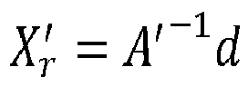
- Thus it is possible to specify a constraint on the number of bins under-covered (with a constraint of the form xi ≥ K) or over-covered (with a constraint of the form xi ≤ k).
- According to a particular feature, if the additional constraint is of the form xi ≥ K, the selected one of the distances xi is the one having an index i corresponding to max(di), and, if the additional constraint is of the form xi ≤ k, the selected one of the distances xi is the one having an index i corresponding to min(di).
- According to a particular feature, the steering information comprise:
- a directed distance DC from the sail line to a current position of the seismic vessel, having a positive value when the seismic vessel is on the right of the sail line, when considering the direction of the sail line; and
- a desired track offset DTO, which is a directed distance from the sail line to a desired position of the seismic vessel, having a positive value when the seismic vessel is on the right of the sail line when considering the direction of the sail line, DTO being defined as follows: DTO = DC + D.
- Thus the proposed solution can be used with a navigation system which typically receives two control settings: the steering offset (DTO) and the distance DC.
- In a first implementation, said n reflexion points are reflexion points associated with an acoustic linear antenna towed by said seismic vessel and comprising receivers, said receivers receiving signals generated by at least one source and reflected by subsurface's layers of the sea at said n reflexion points. The receivers are divided in a plurality of offset classes. Said steps a) and b) are carried out for at least two offset classes of said plurality, a distance D being computed for each offset class. The method comprises a step b') of computing a final distance Df on the basis of the distances D computed for said at least two offset classes. In said step c) the steering information comprise, or are based, on the final distance Df.
- Thus several (and possibly all) the offset classes are taken into account. The process is customizable by the user.
- In a second implementation, said steps a) and b) are carried out for at least two previous preplot lines, a distance D being computed for each previous preplot line. The method comprises a step b") of computing a resulting distance Dr on the basis of the distances D computed for said at least two previous preplot lines. In said step c) the steering information comprise, or are based, on the resulting distance Dr.
- Thus several previous preplot lines are taken into account.
- In a third implementation, for each of said for at least two previous preplot lines:
- said steps a) and b) are carried out for each of said at least two offset classes, and
- said step b') is carried out, enabling to output the final distance Df on the basis of the distances D computed for said at least two offset classes,
- This third implementation combines the aforesaid first and second implementations. Thus several offset classes and several previous preplot lines are taken into account.
- In another embodiment, the invention pertains to a computer program product comprising program code instructions for implementing the above-mentioned method (in any of its different embodiments) when said program is executed on a computer or a processor.
- In another embodiment, the invention pertains to a non-transitory computer-readable carrier medium, storing a program which, when executed by a computer or a processor causes the computer or the processor to carry out the above-mentioned method (in any of its different embodiments).
- In another embodiment, the invention pertains to a device for steering a seismic vessel associated with a sail line, ccomprising:
- means for computing distances di , i ∈ {1 ... n}, from n reflexion points to a boundary of a binning coverage zone associated with a previous preplot line;
- means for computing a distance D, from said n reflexion points to n target reflexion points, as a function of said distances di ; and
- means for providing steering information comprising or based on the distance D to a navigation system or to an operator of a navigation system, to alter the course of the seismic vessel.
- Advantageously, the device comprises means for implementing the steps it performs in the method for steering as described above, in any of its various embodiments.
- Other features and advantages of embodiments of the invention shall appear from the following description, given by way of an indicative and non-exhaustive examples and from the appended drawings, of which:
-
Figure 1 , already discussed in relation to the prior art, illustrates the notions of bin, reflexion point and offset classes; -
Figure 2 , already discussed in relation to the prior art, illustrates the notions of preplot line and associated binning coverage zone; -
Figure 3 illustrates the idea of the proposed solution; -
Figure 4 shows the simplified structure of a device according to a particular embodiment of the invention; -
Figure 5 is a flowchart of a particular embodiment of the method according to the invention; -
Figures 6A and 6B show a vessel before (FIG. 6A ) and after (FIG. 6B ) modification of the course of the vessel, according to the proposed solution; and -
Figures 7A and 7B illustrate the difference between a case without use of an additional constraint (figure 7A ) and a case with use of an additional constraint (figure 7B ), this additional constraint preventing some bins to be over-covered, in a particular embodiment of the method according to the invention. - In all of the figures of the present document, identical elements and steps are designated by the same numerical reference sign.
- Referring now to
figure 5 , we present a steering method according to a particular embodiment of the invention. This method is carried out by a device (for more details about this device, see below description offigure 4 ). - As already discussed in relation to
figure 1 , we consider a seismic vessel associated with a current sail line and a current preplot line (which are often the same). This seismic vessel tows one or several streamers (acoustic linear antennas) comprising receivers. These receivers receive signals generated by at least one source and reflected by the subsurface's layers, at reflexion points. - We assume that the receivers are divided in a plurality of offset classes (e.g. "near offsets", "near-mid offsets", "mid-far offsets", "mid offsets" and "far offsets").
- In the particular embodiment discussed below, the input of the steering method are:
- a current sail line (the current preplot line is often the same as the current sail line);
- one or several known binning boundaries, e.g.:
- o a first known binning boundary, which is the boundary of a binning coverage zone associated with a first previous preplot line. In a particular embodiment, the first previous preplot line is adjacent to the current preplot line (e.g. on the right of the current preplot line when considering the direction of the sail line). In an alternative embodiment, the first previous preplot line is not adjacent to the current preplot line;
- o a second known binning boundary, which is the boundary of a binning coverage zone associated with a second previous preplot line. In a particular embodiment, the second previous preplot line is adjacent to the current preplot line (e.g. on the left of the current preplot line when considering the direction of the sail line). In an alternative embodiment, the second previous preplot line is not adjacent to the current preplot line;
- the positions (xi,yi) of the reflexion points (which can be possibly extrapolated, i.e. computed anticipatively by extrapolation), e.g.:
- o for each offset class, the positions of n first reflexion points of the external streamer relative to the first known binning boundary (i.e. the closest streamer to the first known binning boundary);
- o for each offset class, the positions of n second reflexion points of the external streamer relative to the second known binning boundary (i.e. the closest streamer to the second known binning boundary).
- An external streamer relative to a binning boundary is the closest streamer to this binning boundary, among a plurality of streamers towed by the seismic vessel.
- The outputs of the steering method are steering information to alter the course of the vessel.
- A binning boundary is a broken line, whose format is unspecified. The only requirement is to be able to compute a distance from a reflexion point to this broken line, and this distance shall be unique.
- In
step 51, the device selects one of the first and second previous preplot lines. Then for the selected previous preplot line, the device carries outsteps 52 to 57. - In
step 52, the device selects one of the offset classes. Then for the selected offset class, the device carries outsteps - In
step 53, the device computes distances di , i ∈ {1 ...n}, from n reflexion points of the external streamer to a binning boundary of the binning coverage zone associated with the selected previous preplot line. - For example, if we assume the selected previous preplot line is the first previous preplot line, the distances di are computed from the first reflexion points to the first known binning boundary.
- In a particular implementation, the distances di are directed distances having a positive value when the binning boundary is on the right of the reflexion points when considering the direction of the sail line.
- In
step 54, the device computes and stores a distance D, from the n reflexion points to n target reflexion points, as a function of the distances di . - The distance D is a constant directed distance having a positive value when the target reflexion points are on the right of the reflexion points when considering the direction of the sail line.
- The distance D is computed so that a function f(X) is minimal, with X = {x 1,...,x n,D} and D = xi + di , i ∈ {1...n}.
- Each of the distances xi is a directed distance from the binning boundary to one of the n target reflexion points, having a positive value when the target reflexion point is on the right of the binning boundary when considering the direction of the sail line.
- In a particular embodiment, the function f(X) is defined as:

with x = {x 1 ,..., xn }
and ε a reduction coefficient minimizing the influence of D2 (e.g. ε is a small number, e.g.: 10-1 ≤ ε ≤ 10-12). - The problem is mathematically equivalent to minimise f(X) under the constraints AX = d, where d is a column matrix (d = {d1,,...,dn}), X is also is a column matrix (X = {x1,...,xn, D}) and A is a matrix comprising an identity matrix In multiplied by -1, and a (n+1)th column comprising n ones.
- The unknown is X, i.e. the distances xi and the distance D.
- For example, if n = 2, we have two constraints:


and the equation AX = d is:
- Hence the problem is solved as follows, using Lagrange parameters:


- For example, if n=2:

- Hence

- And finally:

- In other words, the value of X, referred to as result Xr , which minimizes f(X) is computed as:

- From Xr , D is obtained (it is the last line).
- In an alternative embodiment of
step 54, at least one additional constraint is set and the process is slightly different. The at least one additional constraint is of the form xi ≤ k or xi ≥ K, k and K being arbitrary real numbers. After the calculation described above is done, which gives the result Xr , the following supplemental steps are carried out: - verifying that the distances xi comprised in the result Xr satisfy the at least one additional constraint;
- if the at least one additional constraint is satisfied by the distances xi comprised in the result Xr , Xr is retained as final result;
- if the at least one additional constraint is not satisfied by at least one of the distances xi comprised in the result Xr :
- (a) for each additional constraint, selecting one of the distances xi , which does not satisfy this additional constraint. In a particular implementation, if the additional constraint is of the form xi ≥ K, the selected one of the distances xi is the one having an index i corresponding to max(di), and if the additional constraint is of the form xi ≤ k, the selected one of the distances xi is the one having an index i corresponding to min(di);
- (b) for each additional constraint, adding a supplemental line in the matrix A (which thus becomes A'). Each supplemental line describes an equality constraint xi = k or xi = K corresponding to this additional constraint for the selected one of the distances xi ;
- (c) computing a final result


- In an alternative embodiment of above step (a), the selected one of the distances xi is not corresponding to max(di) or min(di). Then, steps (a), (b) and (c) are carried out iteratively (each iteration with one of the distances xi which do not satisfy the at least one additional constraint), until a final result

- Let's take again the example with n = 2 and the following two constraints:

and we assume the following equality constraint is added:
- Then the equation A'X = d is:

- A more detailed example of the alternative embodiment of
step 54 is given below, in relation tofigures 7A and 7B . -
Steps steps step 55, the device checks whether all the offset classes have already been selected. If all the offset classes have already been selected, the process goes to step 57. Otherwise, it goes to step 56, in which the device selects another offset class, not yet selected. - In
step 57, the device computes a final distance Df on the basis of the distances D computed for the different offset classes. Df is for example a weighted average of these distances D (i.e. a weighted average over the offset classes). -
Steps steps 52 to 57 for each previous preplot line. Instep 58, the device checks whether all the previous preplot lines have already been selected. If all the previous preplot lines have already been selected, the process goes to step 510. Otherwise, it goes to step 59, in which the device selects another previous preplot line, not yet selected. - In
step 510, the device computes a resulting distance Dr on the basis of the final distances Df computed for the different previous preplot lines. Dr is for example a weighted average of these final distances Df (i.e. a weighted average over the previous preplot lines). - In
step 511, the device provides steering information comprising, or based on, the resulting distance Dr to a navigation system or to an operator of a navigation system, to alter the course of the seismic vessel. In other words, the vessel is controlled (either automatically or by suggestion to an operator) by the steering information. - In a particular embodiment, the steering information comprise:
- a directed distance DC from the sail line to a current position of the seismic vessel, having a positive value when the seismic vessel is on the right of the sail line, when considering the direction of the sail line; and
- a desired track offset DTO, which is a directed distance from the sail line to a desired position of the seismic vessel, having a positive value when the seismic vessel is on the right of the sail line when considering the direction of the sail line, DTO being defined as follows: DTO = DC + Dr.
-
Figure 3 illustrates the idea of the proposed solution. - The current sail line is referenced 30, having a direction symbolized by the arrow referenced 33.
- A binning boundary (of the binning coverage zone associated with a previous preplot line) is shown and referenced 31.
- The reflexion points are represented as black discs and referenced 1. The target reflexion points are represented as black circles and referenced 1'.
- Four distances di (d 1 , d 2, d 3 and d 4 ) and four distances xi (x 1 , x 2 , x 3 and x 4) are shown.
- The distance D (directed distance from the reflexion points 1 to the target reflexion points 1') is shown. In this example, D has a positive value, considering the above sign convention (D has a positive value when the target reflexion points are on the right of the reflexion points when considering the direction (see arrow referenced 33) of the sail line 30).
-
Figures 6A and 6B show a vessel before (FIG. 6A ) and after (FIG. 6B ) modification of the course of thevessel 6, according to the proposed solution. - As in
figure 3 , the current sail line is referenced 30, the known binning boundary is referenced 31, the reflexion points are represented as black discs and referenced 1, and the target reflexion points are represented as black circles and referenced 1'. - In
figure 6A (i.e. before modification of the course of the vessel 6), the following distances are shown: - the resulting distance Dr (from the reflexion points 1 to the target reflexion points 1') is shown. In this example, Dr has a posititive value, considering the above sign convention;
- the distance DC is shown (directed distance from the
sail line 30 to a current position of the seismic vessel 6). In this example, DC has a positive value, considering the above sign convention (DC has a positive value when the seismic vessel is on the right of the sail line, when considering the direction (see arrow referenced 33) of the sail line); and - the desired track offset DTO (directed distance from the sail line to a desired position of the seismic vessel 6). In this example, DTO has a positive value, considering the above sign convention (DTO has a positive value when the seismic vessel is on the right of the sail line when considering the direction (see arrow referenced 33) of the sail line). DTO is defined as follows: DTO = DC + Dr.
- In
figure 6B , i.e. after modification of the course of thevessel 6, we can see that thevessel 6 has reached the desired position: the distance from the sail line to the current position of theseismic vessel 6 is equal to DTO. In other words, we have DTO=DC, and compared tofigure 6A , the vessel has moved (of the distance Df) towards the known binning boundary referenced 31. Thus, the binning coverage zone associated with the current preplot line is juxtaposed with the binning coverage zone associated with the previous preplot line. -
Figures 7A and 7B illustrate the difference between a case without use of an additional constraint (figure 7A ) and a case with use of an additional constraint (figure 7B ), this additional constraint preventing some bins to be over-covered, in a particular embodiment of the method according to the invention. This is a more detailed example of the alternative embodiment ofstep 54. - In
figure 7A , we assume there is no additional constraint. - In this example, n = 3, therefore we have the following three constraints:
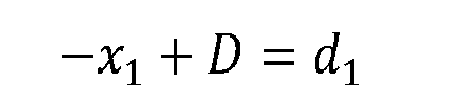


- We assume the device computes the distances and obtains: d 1 = 5, d 2 = 6 and d 3=7.
- Then the equation AX = d is:

- From Xr = C -1 AT(AC -1 AT) - 1d, we obtain:

- This result Xr is illustrated by
figure 7A : x 1 = 1, x 2 = 0, x 3 = -1 and D = 6. - In
figure 7B , we assume there is one additional constraint of the form xi ≤ 0,i.e.k = 0. - The distance x 1 comprised in the result Xr doesn't satisfy the additional constraint. Therefore Xr is not retained as final result and the following steps are carried out:
- selecting x 1 (in this example this selection is easy since it is the only distance x 1 which does not satisfy the additional constraint;
- to describe an equality constraint x 1 = 0, a supplemental line is added in the matrix A, which thus becomes A' a square matrix (4,4). The equation A'X = d is:

- From


- This final result

figure 7B : - x 1 = 0, x 2 = -1, x 3 = -2 and D = 5.
- With this final result, the additional constraint is satisfied by all distances xi , including x1. Therefore, there is no bin over-covered.
-
Figure 4 shows the simplified structure of a device (machine) according to a particular embodiment of the invention, which carries out the method shown inFigure 5 for example. This device is comprised for example in the vessel (e.g. in the integrated navigation system INS). - The
device 40 comprises a non-volatile memory 41 (e.g. a read-only memory (ROM) or a hard disk), a volatile memory 43 (e.g. a random access memory or RAM) and aprocessor 42. Thenon-volatile memory 41 is a non-transitory computer-readable carrier medium. It stores executable program code instructions, which are executed by theprocessor 42 in order to enable implementation of the method described above withfigure 5 . - Upon initialization, the aforementioned program code instructions are transferred from the
non-volatile memory 41 to thevolatile memory 43 so as to be executed by theprocessor 42. Thevolatile memory 43 likewise includes registers for storing the variables and parameters required for this execution. - The devices receives as inputs the
current sail line 44a, the positions of the reflexion points 44b, and the knownbinning boundaries 44c. It generates as output steering information, e.g. the desired track offset (DTO) 45a and thedistance DC 45b described above. - All the steps of the above steering method can be implemented equally well:
- by the execution of a set of program code instructions executed by a reprogrammable computing machine such as a PC type apparatus, a DSP (digital signal processor) or a microcontroller. This program code instructions can be stored in a non-transitory computer-readable carrier medium that is detachable (for example a floppy disk, a CD-ROM or a DVD-ROM) or non-detachable; or
- by a dedicated machine or component, such as an FPGA (Field Programmable Gate Array), an ASIC (Application-Specific Integrated Circuit) or any dedicated hardware component.
- In other words, the invention is not limited to a purely software-based implementation, in the form of computer program instructions, but that it can also be implemented in hardware form or any form combining a hardware portion and a software portion.
Claims (15)
- Method for steering a seismic vessel (6) associated with a sail line (30), characterized in that it comprises:a) computing (53) distances di , i ∈ {1 ... n}, from n reflexion points (1) to a boundary (31) of a binning coverage zone associated with a previous preplot line;b) computing (54) a distance D, from said n reflexion points to n target reflexion points (1'), as a function of said distances di ; andc) providing (511) steering information comprising or based on the distance D to a navigation system or to an operator of a navigation system, to alter the course of the seismic vessel.
- Method according to claim 1, characterized in that said previous preplot line is adjacent to a current preplot line.
- Method according to any one of the claims 1 to 2, characterized in that said n reflexion points are reflexion points associated with an external acoustic linear antenna, which is the closest acoustic linear antenna to said boundary among a plurality of acoustic linear antennas towed by said seismic vessel.
- Method according to any one of the claims 1 to 3, characterized in that said distances di are directed distances having a positive value when said boundary is on the right of the reflexion points when considering the direction of the sail line, and in that said distance D is a constant directed distance having a positive value when the target reflexion points are on the right of the reflexion points when considering the direction of the sail line, and so that a function f(X) is minimal, with X = {x1,...,x n, D}, said distance D being defined as: D = xi + di , i ∈ {1 ... n} and, each of the distances xi being a directed distance from said boundary to one of the n target reflexion points, having a positive value when said target reflexion point is on the right of said boundary when considering the direction of the sail line.
- Method according to claim 4, characterized in that the function f(X) is defined as:

- Method according to claim 5, characterized in that the value of X, referred to as result Xr , which minimizes f(X) is computed in step b) as: Xr = C -1 AT(AC -1 AT) -1 d, with:- d a column matrix comprising the distances di , i ∈ {1 ... n};- C a matrix (n+1,n+1) comprising: an identity matrix In' a (n+1)th line comprising n zeroes then ε, and a (n+1)th column comprising n zeroes then ε; and- A a matrix (n,n+1) such that: AX = d, i.e. A defining n constraints : -xi + D = di , i ∈ {1 ... n} and comprising: an identity matrix In multiplied by -1, and a (n+1)th column comprising n ones.
- Method according to claim 6, characterized in that at least one additional constraint is set, of the form xi ≤ k or xi ≥ K, k and K being arbitrary real numbers, and in that said step b) comprises the following supplemental steps:- verifying that the distances xi comprised in the result Xr satisfy said at least one additional constraint;- if said at least one additional constraint is satisfied by the distances xi comprised in the result Xr , Xr is retained as final result;- if said at least one additional constraint is not satisfied by at least one of the distances xi comprised in the result Xr :* for each additional constraint, selecting one of the distances xi , which does not satisfy said additional constraint;* for each additional constraint, adding a supplemental line in said matrix A, which thus becomes A', each supplemental line describing an equality constraint xi = k or xi = K corresponding to said additional constraint for the selected one of the distances xi ;* computing a final result


- Method according to claim 7, characterized in that, if the additional constraint is of the form xi ≥ K, the selected one of the distances xi is the one having an index i corresponding to max(di), and in that, if the additional constraint is of the form xi ≤ k, the selected one of the distances xi is the one having an index i corresponding to min(di).
- Method according to any one of the claims 1 to 8, characterized in that the steering information comprise:- a directed distance DC from the sail line to a current position of the seismic vessel, having a positive value when the seismic vessel is on the right of the sail line, when considering the direction of the sail line; and- a desired track offset DTO, which is a directed distance from the sail line to a desired position of the seismic vessel, having a positive value when the seismic vessel is on the right of the sail line when considering the direction of the sail line, DTO being defined as follows: DTO = DC + D.
- Method according to any one of the claims 1 to 9, characterized in that said n reflexion points are reflexion points associated with an acoustic linear antenna towed by said seismic vessel and comprising receivers, said receivers receiving signals generated by at least one source and reflected by subsurface's layers of the sea at said n reflexion points,
in that the receivers are divided in a plurality of offset classes,
in that said steps a) and b) are carried out for at least two offset classes of said plurality, a distance D being computed for each offset class,
in that the method comprises a step b') of computing a final distance Df on the basis of the distances D computed for said at least two offset classes,
and in that in said step c) the steering information comprise, or are based, on the final distance Df. - Method according to any one of the claims 1 to 9, characterized in that said steps a) and b) are carried out for at least two previous preplot lines, a distance D being computed for each previous preplot line,
in that the method comprises a step b") of computing a resulting distance Dr on the basis of the distances D computed for said at least two previous preplot lines,
and in that in said step c) the steering information comprise, or are based, on the resulting distance Dr. - Method according to claims 10 and 11, characterized in that, for each of said for at least two previous preplot lines:- said steps a) and b) are carried out for each of said at least two offset classes, and- said step b') is carried out, enabling to output the final distance Df on the basis of the distances D computed for said at least two offset classes,and in that in said step b"), the resulting distance Dr is computed on the basis of the final distance Df computed for said at least two previous preplot lines.
- Computer program product characterized in that it comprises program code instructions for implementing the method according to at least one of the claims 1 to 12, when said program is executed on a computer or a processor.
- A non-transitory computer-readable carrier medium storing a computer program product according to claim 13.
- Device for steering a seismic vessel (6) associated with a sail line (30), characterized in that it comprises:- means (42) for computing distances di , i ∈ {1... n}, from n reflexion points (1) to a boundary (31) of a binning coverage zone associated with a previous preplot line;- means (42) for computing a distance D, from said n reflexion points to n target reflexion points (1'), as a function of said distances di ; and- means (42) for providing steering information comprising or based on the distance D to a navigation system or to an operator of a navigation system, to alter the course of the seismic vessel.
Priority Applications (7)
| Application Number | Priority Date | Filing Date | Title |
|---|---|---|---|
| EP13306904.7A EP2889646A1 (en) | 2013-12-31 | 2013-12-31 | Method and device for steering a seismic vessel, on the basis of boundaries of binning coverage zones |
| CA2875220A CA2875220A1 (en) | 2013-12-31 | 2014-12-16 | Method and device for steering a seismic vessel, on the basis of boundaries of binning coverage zones |
| MX2014015849A MX350926B (en) | 2013-12-31 | 2014-12-18 | Method and device for steering a seismic vessel, on the basis of boundaries of binning coverage zones. |
| BR102014032185A BR102014032185A2 (en) | 2013-12-31 | 2014-12-22 | method and device for steering a seismic vessel based on the boundary coverage zones |
| RU2014153501A RU2014153501A (en) | 2013-12-31 | 2014-12-26 | METHOD AND DEVICE FOR CONTROLLING A SEISMIC VESSEL ON THE BASIS OF BOUNDARY ZONE BOUNDARIES |
| CN201410841758.8A CN104749616A (en) | 2013-12-31 | 2014-12-30 | Method and device for steering a seismic vessel, on the basis of boundaries of binning coverage zones |
| US14/586,175 US9284033B2 (en) | 2013-12-31 | 2014-12-30 | Method and device for steering a seismic vessel, on the basis of boundaries of binning coverage zones |
Applications Claiming Priority (1)
| Application Number | Priority Date | Filing Date | Title |
|---|---|---|---|
| EP13306904.7A EP2889646A1 (en) | 2013-12-31 | 2013-12-31 | Method and device for steering a seismic vessel, on the basis of boundaries of binning coverage zones |
Publications (1)
| Publication Number | Publication Date |
|---|---|
| EP2889646A1 true EP2889646A1 (en) | 2015-07-01 |
Family
ID=49920101
Family Applications (1)
| Application Number | Title | Priority Date | Filing Date |
|---|---|---|---|
| EP13306904.7A Ceased EP2889646A1 (en) | 2013-12-31 | 2013-12-31 | Method and device for steering a seismic vessel, on the basis of boundaries of binning coverage zones |
Country Status (7)
| Country | Link |
|---|---|
| US (1) | US9284033B2 (en) |
| EP (1) | EP2889646A1 (en) |
| CN (1) | CN104749616A (en) |
| BR (1) | BR102014032185A2 (en) |
| CA (1) | CA2875220A1 (en) |
| MX (1) | MX350926B (en) |
| RU (1) | RU2014153501A (en) |
Cited By (2)
| Publication number | Priority date | Publication date | Assignee | Title |
|---|---|---|---|---|
| EP3220167A1 (en) * | 2016-03-15 | 2017-09-20 | CGG Services SAS | Steering for coverage in seismic surveys |
| NO20171320A1 (en) * | 2017-08-08 | 2019-02-11 | Polarcus Dmcc | Method and vessel steering module for seismic data acquiring and for routing a vessel, by generating a first straight line from a starting point to an end point and generating offset straight lines |
Citations (8)
| Publication number | Priority date | Publication date | Assignee | Title |
|---|---|---|---|---|
| US20040230379A1 (en) * | 2003-05-14 | 2004-11-18 | Exxonmobil Upstream Research Company | Method for controlling seismic coverage using decision theory |
| US20060268662A1 (en) * | 2005-05-27 | 2006-11-30 | Thorbjorn Rekdal | Method for determination of sufficient acquisition coverage for a marine seismic streamer survey |
| US20070064526A1 (en) * | 2005-08-26 | 2007-03-22 | Holo Andreas T | Automatic systems and methods for positioning marine seismic equipment |
| US20070165486A1 (en) * | 2006-01-19 | 2007-07-19 | Nicolae Moldoveanu | Methods and systems for efficiently acquiring towed streamer seismic surveys |
| US20100118645A1 (en) * | 2008-11-08 | 2010-05-13 | Kenneth Welker | Coil shooting mode |
| US20120300583A1 (en) * | 2011-05-23 | 2012-11-29 | Ion Geophysical Corporation | Method and apparatus for determining a location to acquire geophysical data |
| US20130051175A1 (en) * | 2011-08-24 | 2013-02-28 | Bengt Mikael Boberg | Quality-Based Steering Methods and Systems for 4D Geophysical Surveys |
| US20130155805A1 (en) * | 2011-12-15 | 2013-06-20 | Cggveritas Services Sa | Controller and method for steering sources |
Family Cites Families (11)
| Publication number | Priority date | Publication date | Assignee | Title |
|---|---|---|---|---|
| NO944954D0 (en) * | 1994-12-20 | 1994-12-20 | Geco As | Procedure for integrity monitoring in position determination |
| GB9821277D0 (en) * | 1998-10-01 | 1998-11-25 | Geco As | Seismic data acquisition equipment control system |
| US8854918B2 (en) * | 2007-10-04 | 2014-10-07 | Westerngeco L.L.C. | Marine seismic streamer steering apparatus |
| US8976622B2 (en) * | 2008-04-21 | 2015-03-10 | Pgs Geophysical As | Methods for controlling towed marine sensor array geometry |
| US7944774B2 (en) * | 2008-05-07 | 2011-05-17 | Apache Corporation | Method for determining adequacy of seismic data coverage of a subsurface area being surveyed and its application to selecting sensor array geometry |
| US9052411B2 (en) * | 2008-06-13 | 2015-06-09 | Westerngeco L.L.C. | Method to determine the deviation of seismic equipment from a planned curved path |
| US8391101B2 (en) * | 2008-07-03 | 2013-03-05 | Conocophillips Company | Marine seismic acquisition with controlled streamer flaring |
| US8902696B2 (en) * | 2009-04-03 | 2014-12-02 | Westerngeco L.L.C. | Multiwing surface free towing system |
| NO332563B1 (en) * | 2009-07-07 | 2012-10-29 | Kongsberg Seatex As | System and method for positioning instrumented rope cable in water |
| US8792297B2 (en) * | 2010-07-02 | 2014-07-29 | Pgs Geophysical As | Methods for gathering marine geophysical data |
| US9116257B2 (en) * | 2012-05-07 | 2015-08-25 | Fugro Norway As | Method and apparatus for sea current aided, enhanced azimuth seismic data acquisition |
-
2013
- 2013-12-31 EP EP13306904.7A patent/EP2889646A1/en not_active Ceased
-
2014
- 2014-12-16 CA CA2875220A patent/CA2875220A1/en not_active Abandoned
- 2014-12-18 MX MX2014015849A patent/MX350926B/en active IP Right Grant
- 2014-12-22 BR BR102014032185A patent/BR102014032185A2/en not_active IP Right Cessation
- 2014-12-26 RU RU2014153501A patent/RU2014153501A/en not_active Application Discontinuation
- 2014-12-30 CN CN201410841758.8A patent/CN104749616A/en active Pending
- 2014-12-30 US US14/586,175 patent/US9284033B2/en active Active
Patent Citations (8)
| Publication number | Priority date | Publication date | Assignee | Title |
|---|---|---|---|---|
| US20040230379A1 (en) * | 2003-05-14 | 2004-11-18 | Exxonmobil Upstream Research Company | Method for controlling seismic coverage using decision theory |
| US20060268662A1 (en) * | 2005-05-27 | 2006-11-30 | Thorbjorn Rekdal | Method for determination of sufficient acquisition coverage for a marine seismic streamer survey |
| US20070064526A1 (en) * | 2005-08-26 | 2007-03-22 | Holo Andreas T | Automatic systems and methods for positioning marine seismic equipment |
| US20070165486A1 (en) * | 2006-01-19 | 2007-07-19 | Nicolae Moldoveanu | Methods and systems for efficiently acquiring towed streamer seismic surveys |
| US20100118645A1 (en) * | 2008-11-08 | 2010-05-13 | Kenneth Welker | Coil shooting mode |
| US20120300583A1 (en) * | 2011-05-23 | 2012-11-29 | Ion Geophysical Corporation | Method and apparatus for determining a location to acquire geophysical data |
| US20130051175A1 (en) * | 2011-08-24 | 2013-02-28 | Bengt Mikael Boberg | Quality-Based Steering Methods and Systems for 4D Geophysical Surveys |
| US20130155805A1 (en) * | 2011-12-15 | 2013-06-20 | Cggveritas Services Sa | Controller and method for steering sources |
Cited By (7)
| Publication number | Priority date | Publication date | Assignee | Title |
|---|---|---|---|---|
| EP3220167A1 (en) * | 2016-03-15 | 2017-09-20 | CGG Services SAS | Steering for coverage in seismic surveys |
| US10520624B2 (en) | 2016-03-15 | 2019-12-31 | Cgg Services Sas | Steering for coverage in seismic surveys |
| NO20171320A1 (en) * | 2017-08-08 | 2019-02-11 | Polarcus Dmcc | Method and vessel steering module for seismic data acquiring and for routing a vessel, by generating a first straight line from a starting point to an end point and generating offset straight lines |
| WO2019031969A1 (en) * | 2017-08-08 | 2019-02-14 | Polarcus Dmcc | Method and vessel steering module for seismic data acquiring and for routing a vessel |
| NO343551B1 (en) * | 2017-08-08 | 2019-04-01 | Polarcus Dmcc | Method and vessel steering module for seismic data acquiring and for routing a vessel, by generating a first straight line from a starting point to an end point and generating offset straight lines |
| GB2582064A (en) * | 2017-08-08 | 2020-09-09 | Polarcus Shipholding As | Method and vessel steering module for seismic data acquiring and for routing a vessel |
| GB2582064B (en) * | 2017-08-08 | 2022-03-02 | Shearwater Invest As | Method and vessel steering module for seismic data acquiring and for routing a vessel |
Also Published As
| Publication number | Publication date |
|---|---|
| CA2875220A1 (en) | 2015-06-30 |
| CN104749616A (en) | 2015-07-01 |
| RU2014153501A3 (en) | 2018-05-14 |
| BR102014032185A2 (en) | 2015-09-15 |
| US20150183502A1 (en) | 2015-07-02 |
| MX2014015849A (en) | 2015-08-27 |
| US9284033B2 (en) | 2016-03-15 |
| RU2014153501A (en) | 2016-07-20 |
| MX350926B (en) | 2017-09-26 |
Similar Documents
| Publication | Publication Date | Title |
|---|---|---|
| US9927540B2 (en) | Method for determining a collision free sail path of at least one vessel of a fleet of vessels, corresponding device, computer program product and non-transitory computer-readable carrier medium | |
| EP4258025B1 (en) | Marine vibrator directive source survey | |
| US9121956B2 (en) | Method and apparatus for determining a location to acquire geophysical data | |
| MX2010013018A (en) | Method to determine the deviation of seismic equipment from a planned curved path. | |
| Widmaier et al. | Redefining marine towed-streamer acquisition | |
| RU2712793C2 (en) | Real-time data filling in marine seismic surveys using an independent seismic source | |
| JP6655022B2 (en) | Synthetic antenna sonar and method for forming a synthetic antenna beam | |
| AU2019346258B2 (en) | On-site 3D geological mapping system and method using device for displaying boundary surface of geological elements | |
| EP2877880B1 (en) | System and method for migration velocity modeling | |
| Ligi et al. | Mapping of seafloor hydrothermally altered rocks using geophysical methods: Marsili and Palinuro seamounts, southern Tyrrhenian Sea | |
| US20160259076A1 (en) | Method for determining a sail path of at least one vessel of a fleet of vessels, corresponding device, computer program product and non-transitory computer-readable carrier medium | |
| EP4285164B1 (en) | Method for steering a vessel, related navigation system and method for seismic data acquisition | |
| US10520624B2 (en) | Steering for coverage in seismic surveys | |
| US9284033B2 (en) | Method and device for steering a seismic vessel, on the basis of boundaries of binning coverage zones | |
| US20160363682A1 (en) | Efficient survey design to in-fill a pre-existing plural vessels seismic survey | |
| US10042065B2 (en) | Method and device for steering a seismic vessel | |
| US6807513B2 (en) | Method for determining a spatial quality index of regionalized data | |
| CN113109864A (en) | Seismic exploration shot point observing changing method and device | |
| US10520600B1 (en) | Methods and systems for automated mission area segmentation | |
| Ferreira et al. | Exploratory-scale OBN seismic acquisition in Santos Basin | |
| Samuel et al. | Resolving the Divide: Comparative Performance of Side Scan Sonar and Synthetic Aperture Sonar in Offshore Survey and Regulatory Compliance | |
| US20150219778A1 (en) | Method for Obtaining an Adapted Sequence of Shot Predictions From a Raw Sequence of Shot Predictions | |
| TU et al. | Robust optimal synthetic aperture imaging of towed streamer electromagnetic data | |
| Engelmark et al. | Advances in marine electromagnetic (EM) efficiency with a towed acquisition system |
Legal Events
| Date | Code | Title | Description |
|---|---|---|---|
| PUAI | Public reference made under article 153(3) epc to a published international application that has entered the european phase |
Free format text: ORIGINAL CODE: 0009012 |
|
| 17P | Request for examination filed |
Effective date: 20131231 |
|
| AK | Designated contracting states |
Kind code of ref document: A1 Designated state(s): AL AT BE BG CH CY CZ DE DK EE ES FI FR GB GR HR HU IE IS IT LI LT LU LV MC MK MT NL NO PL PT RO RS SE SI SK SM TR |
|
| AX | Request for extension of the european patent |
Extension state: BA ME |
|
| R17P | Request for examination filed (corrected) |
Effective date: 20151222 |
|
| RBV | Designated contracting states (corrected) |
Designated state(s): AL AT BE BG CH CY CZ DE DK EE ES FI FR GB GR HR HU IE IS IT LI LT LU LV MC MK MT NL NO PL PT RO RS SE SI SK SM TR |
|
| STAA | Information on the status of an ep patent application or granted ep patent |
Free format text: STATUS: EXAMINATION IS IN PROGRESS |
|
| 17Q | First examination report despatched |
Effective date: 20180525 |
|
| STAA | Information on the status of an ep patent application or granted ep patent |
Free format text: STATUS: THE APPLICATION HAS BEEN REFUSED |
|
| 18R | Application refused |
Effective date: 20210606 |