EP2889601A1 - Ein verfahren zur herstellung von schaufeln - Google Patents
Ein verfahren zur herstellung von schaufeln Download PDFInfo
- Publication number
- EP2889601A1 EP2889601A1 EP14194895.0A EP14194895A EP2889601A1 EP 2889601 A1 EP2889601 A1 EP 2889601A1 EP 14194895 A EP14194895 A EP 14194895A EP 2889601 A1 EP2889601 A1 EP 2889601A1
- Authority
- EP
- European Patent Office
- Prior art keywords
- blade
- blades
- airfoil
- component
- performance
- Prior art date
- Legal status (The legal status is an assumption and is not a legal conclusion. Google has not performed a legal analysis and makes no representation as to the accuracy of the status listed.)
- Granted
Links
Images

Classifications
-
- F—MECHANICAL ENGINEERING; LIGHTING; HEATING; WEAPONS; BLASTING
- F01—MACHINES OR ENGINES IN GENERAL; ENGINE PLANTS IN GENERAL; STEAM ENGINES
- F01D—NON-POSITIVE DISPLACEMENT MACHINES OR ENGINES, e.g. STEAM TURBINES
- F01D5/00—Blades; Blade-carrying members; Heating, heat-insulating, cooling or antivibration means on the blades or the members
- F01D5/12—Blades
- F01D5/14—Form or construction
- F01D5/141—Shape, i.e. outer, aerodynamic form
-
- G—PHYSICS
- G01—MEASURING; TESTING
- G01M—TESTING STATIC OR DYNAMIC BALANCE OF MACHINES OR STRUCTURES; TESTING OF STRUCTURES OR APPARATUS, NOT OTHERWISE PROVIDED FOR
- G01M9/00—Aerodynamic testing; Arrangements in or on wind tunnels
- G01M9/08—Aerodynamic models
-
- F—MECHANICAL ENGINEERING; LIGHTING; HEATING; WEAPONS; BLASTING
- F01—MACHINES OR ENGINES IN GENERAL; ENGINE PLANTS IN GENERAL; STEAM ENGINES
- F01D—NON-POSITIVE DISPLACEMENT MACHINES OR ENGINES, e.g. STEAM TURBINES
- F01D21/00—Shutting-down of machines or engines, e.g. in emergency; Regulating, controlling, or safety means not otherwise provided for
- F01D21/003—Arrangements for testing or measuring
-
- F—MECHANICAL ENGINEERING; LIGHTING; HEATING; WEAPONS; BLASTING
- F05—INDEXING SCHEMES RELATING TO ENGINES OR PUMPS IN VARIOUS SUBCLASSES OF CLASSES F01-F04
- F05D—INDEXING SCHEME FOR ASPECTS RELATING TO NON-POSITIVE-DISPLACEMENT MACHINES OR ENGINES, GAS-TURBINES OR JET-PROPULSION PLANTS
- F05D2260/00—Function
- F05D2260/81—Modelling or simulation
-
- G—PHYSICS
- G01—MEASURING; TESTING
- G01B—MEASURING LENGTH, THICKNESS OR SIMILAR LINEAR DIMENSIONS; MEASURING ANGLES; MEASURING AREAS; MEASURING IRREGULARITIES OF SURFACES OR CONTOURS
- G01B11/00—Measuring arrangements characterised by the use of optical techniques
- G01B11/24—Measuring arrangements characterised by the use of optical techniques for measuring contours or curvatures
- G01B11/25—Measuring arrangements characterised by the use of optical techniques for measuring contours or curvatures by projecting a pattern, e.g. one or more lines, moiré fringes on the object
-
- G—PHYSICS
- G01—MEASURING; TESTING
- G01B—MEASURING LENGTH, THICKNESS OR SIMILAR LINEAR DIMENSIONS; MEASURING ANGLES; MEASURING AREAS; MEASURING IRREGULARITIES OF SURFACES OR CONTOURS
- G01B5/00—Measuring arrangements characterised by the use of mechanical techniques
- G01B5/004—Measuring arrangements characterised by the use of mechanical techniques for measuring coordinates of points
-
- G—PHYSICS
- G05—CONTROLLING; REGULATING
- G05B—CONTROL OR REGULATING SYSTEMS IN GENERAL; FUNCTIONAL ELEMENTS OF SUCH SYSTEMS; MONITORING OR TESTING ARRANGEMENTS FOR SUCH SYSTEMS OR ELEMENTS
- G05B2219/00—Program-control systems
- G05B2219/30—Nc systems
- G05B2219/35—Nc in input of data, input till input file format
- G05B2219/35128—Propeller blade
-
- G—PHYSICS
- G05—CONTROLLING; REGULATING
- G05B—CONTROL OR REGULATING SYSTEMS IN GENERAL; FUNCTIONAL ELEMENTS OF SUCH SYSTEMS; MONITORING OR TESTING ARRANGEMENTS FOR SUCH SYSTEMS OR ELEMENTS
- G05B2219/00—Program-control systems
- G05B2219/30—Nc systems
- G05B2219/37—Measurements
- G05B2219/37617—Tolerance of form, shape or position
-
- G—PHYSICS
- G05—CONTROLLING; REGULATING
- G05B—CONTROL OR REGULATING SYSTEMS IN GENERAL; FUNCTIONAL ELEMENTS OF SUCH SYSTEMS; MONITORING OR TESTING ARRANGEMENTS FOR SUCH SYSTEMS OR ELEMENTS
- G05B2219/00—Program-control systems
- G05B2219/30—Nc systems
- G05B2219/45—Nc applications
- G05B2219/45147—Machining blade, airfoil
Definitions
- the invention relates to a method for producing blades.
- criteria typically tolerance bands
- criteria are defined, as for example in the document WO 2010/099890 A1 is described. If the manufactured blades do not meet the criteria, the corresponding blade is sorted out. It may happen that the classified as bad scoop does not meet the specified tolerances, but still have little to no negative aerodynamic effects. Thus, blades with supposedly poor mechanical dimensions are rejected, although the blades would meet the required structural and aerodynamic criteria. If, on the other hand, the tolerance bands are widened, then blades are found to be good, although they have aerodynamically or structurally disadvantageous properties. So far, narrow tolerance bands are preferred, in which case the rejected blades must be laboriously examined manually by experts with great effort. For a small number of blades, this is a viable option, but not economically viable for mass production with a high number of blades. An automated procedure for this is not yet known.
- the present invention is based on the object to present a method for the production of blades, which are evaluated in particular automated.
- the invention relates to a method for producing blades.
- first of all the three-dimensional geometry of the blade of a blade, in particular a compressor blade, is detected.
- the acquired values are transferred to at least one surface model.
- the surface model is transformed from the measurement state to the operating state.
- the aerodynamic and / or structural mechanical properties of the airfoil are evaluated.
- the performance of a component is evaluated.
- This method is particularly advantageous because it can run automatically. This saves a lot of time and allows many blades to be automatically evaluated in a short time.
- a review by a subject matter expert requires several hours, and this procedure can do the same job in minutes. Furthermore, one obtains improved knowledge about the effect of component deviations on technical targets and can thereby avoid excessive product requirements.
- the three-dimensional geometry of the airfoil is detected optically, in particular by means of stripe patterns. This is particularly advantageous because the entire geometry of the blade can be detected quickly with few shots.
- At least 4 surface models are used when transferring into surface models, wherein a surface for the leading edge, a surface for the trailing edge, a surface for the suction side and a surface for the pressure side is provided.
- This is particularly advantageous since less data is required for the digitization and thus the further data processing can take place more quickly.
- the peculiarities of the corresponding areas can also be taken into account.
- surface model for the filet radii can be taken into account. These are the transition surfaces from the blade to the blade hub.
- a pre-evaluation of the airfoil is performed, with only the blades are further evaluated that do not meet the pre-assessment. This is advantageously prevented that only the supposed rejects is additionally examined. Logically, the airfoils classified as good in the preliminary assessment are therefore not rated further. This saves a lot of time.
- At least one profile section is generated computationally and / or tactilely in the preliminary evaluation by the airfoil.
- the pre-evaluation can be carried out for example by means of a tactile measurement at certain heights of the blade, so that a certain number of profile sections (at least one profile section) arise.
- profile cuts must be within a tolerance band so that the pre-assessment for the corresponding bucket can be successfully evaluated.
- profile sections can also arise purely mathematically. These can be from the point cloud can be determined, which arise in the three-dimensional detection of the airfoil.
- the component is a blade, a grid, a module and / or a turbomachine, in particular a gas turbine.
- a turbomachine in particular a gas turbine.
- an averaged airfoil is calculated after the transfer in at least one surface model, wherein the data of the averaged airfoil are used in the transformation.
- the averaging is carried out as a function of the profile sections of the blades of a grille detected in the preliminary evaluation. This is particularly advantageous because the data processing can be done very quickly, especially because the profile sections of all (classified as good) blades are already present and can be easily processed.
- the grids of a module are arranged relative to one another in such a way that the, in particular aerodynamic, properties at least partially compensate each other.
- a first grid may have a single scoop rated as poor.
- the grid has correspondingly a certain (less good) performance (efficiency).
- another grid has two blades classified as bad.
- this second grid has a certain (less good) performance.
- a further advantageous embodiment of the invention is determined after the assessment of the performance of the component, whether this performance of the component is in the desired. If the performance is sufficient, the component will be assembled. If the performance is insufficient, the component is re-evaluated to determine if the component is post-processable. This is particularly advantageous because only very few blades have to be examined manually afterwards.
- the FIG. 1 shows a schematic flow diagram of the method according to the invention.
- step S1 the blade is designed and the manufacturing tolerances set.
- step S2 the blade is manufactured according to this design.
- step S3 profile sections of the produced blade are generated. This should be briefly on the FIG. 2 To be received.
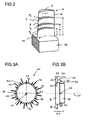
- FIG. 2 is a side view of a compressor blade 2 reproduced.
- the compressor blade 2 has an airfoil 3 with a concave-shaped pressure side 4 and a convex-shaped suction side 6.
- the two sides 4 and 6 open on the left side of the FIG. 2 in the curved front edge 8.
- the suction side 6 and the pressure side 4 open into the trailing edge 10, which is arranged opposite to the front edge 8.
- the blade 3 is formed on a paddle wheel 12 or blade ring. Of this blade ring 12 only part is shown. Between the blade 3 and the blade ring 12 is the fillet 14th arranged.
- step S3 a measuring sensor is then guided once around the blade 3 along the dashed line on the surface of the blade 3 in a tactile measurement, for example at the height h 1 .
- the profile section P 1 is generated from this measurement.
- the process is repeated at the height h 2 to obtain the profile section P 2 .
- the process is repeated at the height h 3 in order to obtain the profile section P 3 .
- the necessary number of profile cuts depends on the particular application. But it may also be sufficient only a profile section.
- step F1 it is determined whether the profile sections of the airfoil 3 are within the requirements. If the requirements in block F1 are met, then the component (here a blade) is assembled or reused in step S12. If the requirements in block F1 are not fulfilled, then in step S4 there takes place a, in particular optical, three-dimensional detection of the airfoil 3. In this case, preferably only the airfoils 3 which were classified as bad in block F1 are optically detected. This creates a point cloud that can not be reasonably processed in terms of data processing technology. Therefore, this point cloud is converted in at least one surface model in step S5. Preferably, four surface models are used, one surface reflecting the trailing edge 10, one surface the leading edge 8, one surface the suction side 6, and one surface the pressure side 4.
- step S6 an averaged airfoil is calculated in which, in particular only, the blades classified as good in block F1 are taken into account.
- the calculation of an averaged airfoil as performed in step S6 is only optional.
- The, in particular averaged, airfoil is transformed in step S7 from the (cold) measuring state to the (hot) operating state. Typically, the measurement takes place at room temperature.
- the operating state may be the state with the highest efficiency, with the highest speed or with the highest operating temperature.
- step S8 the, in particular aerodynamic and / or structural dynamics, properties of the airfoil 3 are determined.
- step S9 the performance of the component, such as the airfoil, the grille, the module or the entire engine is determined.
- the stability limit (pumping limit) is determined depending on the mass flow and the efficiency.
- block F2 it is checked whether the determined performance values are within predetermined requirements. If the requirements in block F2 are fulfilled, the component (here a Shovel) in step S12. If the requirements in block F2 are not met, then in block F3 an inspection takes place in which it is determined whether the airfoil can be reworked with reasonable economic effort. If the requirements in block F3 are met, then the component (here a blade) is reworked or reworked and / or even repaired in step S11. Thereafter, the revised component is assembled in step S12. If the requirements in block F2 are not met, then in step S10, the corresponding component is disposed of. Preferably, steps S4 to S9 are performed automatically.
- step S13 improved design rules can be defined. These also include, for example, wider tolerance bands used in step S3.
- Step S13 may take place immediately after step S8. This must also be done independently of step S8.
- FIGS. 3A and 3B a compressor module 20 is shown.
- the FIG. 3A shows an axial view of the compressor module 20 with a first playpens 22 and a second playpens 24, which has a smaller radius than the first playpeg 22.
- Such a compressor module 20 can be rotated about an axis 21.
- First runner 22 in this example has ten blades 26 classified as good in block F1.
- the first walker 22 in this example has two blades 28 and 30 classified as bad in block F1.
- the second walkway 24 in this example comprises eleven blades 32 classified as good in block F1 and one blade 34 classified as bad in block F1.
- the well rated blades are black lines and the bad ones are black outlined lines with white filling.
- FIG. 3B is a side view of the compressor module 20 from FIG. 3A displayed.
- the two playpens 22 and 24 are connected to each other so that they rotate synchronously in operation at the same speed.
- both the first playpens 22 and the second playpens have cylindrically shaped runners 36 and 38.
- the wheels 36 and 38 are conically shaped.
- On the circumference of the first impeller 36 only three blades are shown and although above and below each classified as a good scoop 26 and in upper third of the badly classified blade 30. The remaining blades of the first gangway 22 were not shown for the understanding.
- first space 40 At the periphery of the first impeller 36 between the upper well classified blade 26 and the upper well classified blade 32 of the second mesh 24, there is a first space 40.
- the non-illustrated vanes are arranged in a turbomachine, which together with the blades 26, 28 and 30 form a first compressor stage.
- a second gap 42 is present.
- the non-illustrated vanes are arranged in a turbomachine, which together with the blades 32 and 34 form a second compressor stage.
- step S9 the performance of the first scrolling lattice 22 is determined.
- step S9 the performance of the second scrolling lattice 24 is determined. It may happen that at least one of the playpens 22 and / or 24 does not fulfill the test in block F2.
- the check in block F2 the badly rated blade 28 of the first gangway 22 is rotated 10 ° clockwise from the 12 o'clock position.
- the badly ranked blades 32 of the second gangway are located at the 9 o'clock position.
- the averaged blade grid is transformed (transferred) in a (hot) operating state. Subsequently, the aerodynamic efficiency and stability of the preliminary screened blade is compared with the averaged blade and evaluated. If this comparison is correct , the screened blade is classified as good and put into operation.
Landscapes
- Physics & Mathematics (AREA)
- Fluid Mechanics (AREA)
- Engineering & Computer Science (AREA)
- General Physics & Mathematics (AREA)
- Mechanical Engineering (AREA)
- General Engineering & Computer Science (AREA)
- Structures Of Non-Positive Displacement Pumps (AREA)
Abstract
Description
- Die Erfindung betrifft ein Verfahren zur Herstellung von Schaufeln.
- Für die Herstellung von Schaufelrädern mit einer Vielzahl an Schaufeln werden Kriterien, typischerweise Toleranzbänder, festgelegt, wie beispielsweise in der Druckschrift
WO 2010/099 890 A1 beschrieben ist. Erfüllen die hergestellten Schaufeln die Kriterien nicht, so wird die entsprechende Schaufel aussortiert. Dabei kann es vorkommen, dass die als schlecht eingestufte Schaufel zwar die festgelegten Toleranzen nicht erfüllt, aber dennoch kaum bis gar keine negativen aerodynamischen Auswirkungen aufweisen. Somit werden Schaufel mit vermeintlich nicht guten mechanischen Abmessungen aussortiert, obwohl die Schaufel die erforderlichen strukturmechanischen und aerodynamischen Kriterien erfüllen würden. Werden dagegen die Toleranzbänder aufgeweitet, so werden Schaufeln dagegen für gut befunden, die allerdings aerodynamisch oder strukturmechanisch nachteilige Eigenschaften aufweisen. Bislang werden enge Toleranzbänder bevorzugt, wobei dann die aussortierten Schaufeln mühsam mit großem Aufwand händisch von Fachexperten untersucht werden müssen. Für eine kleine Anzahl an Schaufeln ist dies ein gangbarer Weg, allerdings für eine Serienfertigung mit einer hohen Schaufelanzahl wirtschaftlich nicht tragbar. Ein dafür automatisiertes Verfahren ist bislang nicht bekannt. - Somit liegt der vorliegenden Erfindung die Aufgabe zu Grunde ein Verfahren zur Herstellung von Schaufeln vorzustellen, die darin insbesondere automatisiert bewertet werden.
- Die Aufgabe wird durch die Merkmale des Anspruchs 1 gelöst.
- Die Erfindung betrifft ein Verfahren zur Herstellung von Schaufeln. Im Verfahren wird zuerst die dreidimensionale Geometrie des Schaufelblatts einer Schaufel, insbesondere einer Verdichterlaufschaufel, erfasst. Anschließend werden die erfassten Werte in mindestens einem Flächenmodell überführt. Das Flächenmodell wird vom Messzustand in den Betriebszustand transformiert. Nach der Transformation werden die aerodynamischen und/oder strukturmechanischen Eigenschaften des Schaufelblattes bewertet. Schließlich wird die Performanz eines Bauteil bewertet.
Dieses Verfahren ist insbesondere vorteilhaft, da es automatisch ablaufen kann. Dies ist sehr zeitsparend und damit können vielen Schaufeln in kurzer Zeit automatisiert bewertet werden. Eine Bewertung durch einen Fachexperten erfordert einige Stunden, wobei dieses Verfahren die gleiche Tätigkeit innerhalb von Minuten erledigen kann. Ferner erlangt man verbesserte Erkenntnis über die Wirkung von Bauteilabweichungen auf technische Zielgrößen und kann dadurch überhöhte Produktanforderungen vermeiden. - In einer weiteren Ausgestaltung der Erfindung wird die dreidimensionale Geometrie des Schaufelblattes optisch, insbesondere mittels Streifenmuster, erfasst. Dies ist insbesondere sehr vorteilhaft, da die komplette Geometrie des Schaufelblatts mit wenigen Aufnahmen schnell erfasst werden kann.
- In einer weiteren vorteilhaften Ausgestaltung der Erfindung wird beim Überführen in Flächenmodelle mindestens 4 Flächenmodelle verwendet werden, wobei eine Fläche für die Vorderkante, eine Fläche für die Hinterkante, eine Fläche für die Saugseite und eine Fläche für die Druckseite vorgesehen ist. Dies ist insbesondere vorteilhaft, da für die Digitalisierung weniger Daten anfallen und somit die weitere Datenverarbeitung schneller erfolgen kann. Durch diese Unterteilung können auch die Eigenheiten der entsprechenden Flächen berücksichtigt werden. Ferner können Flächenmodell für die Filetradien berücksichtigt werden. Das sind die Übergangsflächen vom Schaufelblatt zur Schaufelnabe.
- In einer weiteren vorteilhaften Ausgestaltung der Erfindung wird, vorzugsweise vor der dreidimensionalen geometrischen Erfassung des Schaufelblatts, eine Vorbewertung des Schaufelblattes durchgeführt, wobei nur die Schaufeln weiterbewertet werden, die die Vorbewertung nicht erfüllen. Damit wird in vorteilhafterweise verhindert, dass nur die vermeintliche Ausschussware zusätzlich untersucht wird. Die in der Vorbewertung als gut eingestuften Schaufelblätter werden damit logischerweise nicht weiter bewertet. Dies erspart viel Zeit.
- In einer weiteren vorteilhaften Ausgestaltung der Erfindung wird in der Vorbewertung vom Schaufelblatt mindestens ein Profilschnitt rechnerisch und/oder taktil erzeugt. Die Vorbewertung kann beispielsweise mittels einer taktilen Messung auf bestimmten Höhen des Schaufelblatts erfolgen, so dass eine bestimmte Anzahl an Profilschnitten (mindestens ein Profilschnitt) entstehen. Diese Profilschnitte müssen in einem Toleranzband liegen, damit die Vorbewertung für die entsprechende Schaufel aus erfolgreich bewertet werden kann. Vorzugsweise erfolgt mit den in der Vorbewertung als gut eingestuften Schaufeln keine weitere Analyse. Solche Profilschnitte können auch rein rechnerisch entstehen. Diese können aus der Punktewolke ermittelt werden, die beim dreidimensionalen Erfassen des Schaufelblattes entstehen.
- In einer weiteren vorteilhaften Ausgestaltung der Erfindung ist das Bauteil eine Schaufel, ein Gitter, ein Modul und/oder eine Strömungsmaschine, insbesondere eine Gasturbine. Dies ist insbesondere vorteilhaft, da nicht nur die einzelne Schaufel berücksichtigt und bewertet wird, sondern die konkreten Auswirkungen eines als schlecht eingestuften Schaufelblattes auf das Gitter, Modul und/oder auf das gesamte Triebwerk beurteilt werden können. Konkret wird damit die essentielle Frage beantwortet, ob die mechanischen Abweichungen eine Auswirkung auf beispielsweise den Wirkungsgrad des Gesamtsystems haben. Dies führt dazu, dass weniger Schaufelblätter aussortiert werden und die Produktionskosten gesenkt werden können.
- In einer weiteren vorteilhaften Ausgestaltung der Erfindung wird nach der Überführung in mindestens einem Flächenmodell ein gemitteltes Schaufelblatt berechnet, wobei beim Transformieren die Daten des gemittelten Schaufelblattes verwendet werden. In einer weiteren vorteilhaften Ausgestaltung der Erfindung werden beim Mitteln, vorzugsweise nur, die in der Vorbewertung als gut eingestuften Schaufelblätter berücksichtigt. Dies hat den Vorteil, dass die marginalen Unterschiede in diesen als gut eingestuften Schaufeln ausgemittelt werden.
- In einer weiteren vorteilhaften Ausgestaltung der Erfindung erfolgt die Mittelung in Abhängigkeit von den in der Vorbewertung erfassten Profilschnitte der Schaufelblätter eines Gitters. Dies ist insbesondere vorteilhaft, da die Datenverarbeitung sehr schnell erfolgen kann, insbesondere, weil die Profilschnitte von allen (als gut eingestuften) Schaufeln bereits vorliegen und einfach weiterverarbeitet werden können.
- In einer weiteren vorteilhaften Ausgestaltung der Erfindung werden die Gitter eines Modul derart zueinander angeordnet, dass sich die, insbesondere aerodynamischen, Eigenschaften zu mindestens teilweise kompensieren. Dies ist insbesondere vorteilhaft, da, insbesondere bei einer Reparatur, die Performanz der einzelnen Gitter und/oder eines Moduls beurteilt wird. So kann ein erstes Gitter eine einzige als schlecht eingestufte Schaufel aufweisen. Damit einhergehend weist das Gitter entsprechend eine bestimmte (weniger gute) Performanz (Wirkungsgrad) auf. Ein weiteres Gitter weist beispielsweise zwei als schlecht eingestufte Schaufeln auf. Auch dieses zweite Gitter weist eine bestimmte (weniger gute) Performanz auf. Durch geschickte Anordnung der Gitter zueinander können sich die negativen Wirkungen in der Performanz reduzieren bzw. sogar ganz aufheben. Dies bietet die Möglichkeit sogar Gitter weiter zu verwenden, die für sich genommen eine schlechte Performanz aufweist, jedoch im Zusammenspiel im Gesamtsystem nicht negativ ins Gewicht fallen.
- In einer weiteren vorteilhaften Ausgestaltung der Erfindung wird nach der Beurteilung der Performanz des Bauteils festgestellt, ob diese Performanz des Bauteils im Soll liegt. Wenn die Performanz ausreichend ist, wird das Bauteil montiert wird. Wenn die Performanz nicht ausreichend ist, wird das Bauteil nachbewertet, um festzustellen, ob das Bauteil nachbearbeitbar ist. Dies ist insbesondere vorteilhaft, da damit nur noch sehr wenige Schaufeln händisch nachträglich untersucht werden müssen.
- Weitere Vorteilhafte Ausgestaltung der Erfindung sind in den Unteransprüchen wiedergegeben.
- Im Weiteren werden anhand der schematischen Zeichnung bevorzugte Ausführungsbeispiele der Erfindung näher beschrieben. Dabei zeigen:
-
Figur 1 : einen Ablaufdiagramm des erfindungsmäßen Verfahrens; -
Figur 2 : eine Seitenansicht einer Verdichterschaufel; -
Figur 3A : eine axiale Ansicht eines Verdichtermoduls mit zwei Gittern und -
Figur 3B : eine Seitenansicht des Verdichtermoduls ausFigur 3A . - Die
Figur 1 zeigt einen schematischen Ablaufdiagramm des erfindungsgemäßen Verfahrens. In Schritt S1 wird die Schaufel ausgelegt und auch die Herstelltoleranzen festgesetzt. In Schritt S2 wird die Schaufel nach dieser Auslegung hergestellt. In Schritt S3 werden Profilschnitte der hergestellten Schaufel generiert. Dazu soll kurz auf dieFigur 2 eingegangen werden. - In
Figur 2 ist eine Seitenansicht einer Verdichterschaufel 2 wiedergegeben. Die Verdichterschaufel 2 weist ein Schaufelblatt 3 mit einer konkav geformten Druckseite 4 und einer konvex geformten Saugseite 6 auf. Die beiden Seiten 4 und 6 münden auf der linken Seite derFigur 2 in die gebogene Vorderkante 8. Die Saugseite 6 und die Druckseite 4 münden in die Hinterkante 10, die zur Vorderkante 8 gegenüberliegend angeordnet ist. Das Schaufelblatt 3 ist an einem Schaufelrad 12 bzw. Schaufelring angeformt. Von diesem Schaufelring 12 ist nur ein Teil abgebildet. Zwischen dem Schaufelblatt 3 und dem Schaufelring 12 ist das Filet 14 angeordnet. - In Schritt S3 wird nun bei einer taktilen Messung beispielsweise auf der Höhe h1 ein Messfühler einmal um das Schaufelblatt 3 entlang der gestrichelten Linie auf der Oberfläche des Schaufelblatts 3 geführt. Dabei wird aus dieser Messung der Profilschnitt P1 generiert. In einer weiteren Messung wird der Vorgang auf der Höhe h2 wiederholt, um den Profilschnitt P2 zu erhalten. In einer weiteren Messung wird der Vorgang auf der Höhe h3 wiederholt, um den Profilschnitt P3 zu erhalten. Die notwendige Anzahl der Profilschnitte hängt von der jeweiligen Anwendung ab. Es kann aber auch lediglich ein Profilschnitt ausreichend sein.
- In Block F1 wird festgestellt, ob die Profilschnitte des Schaufelblatts 3 innerhalb der Anforderungen liegen. Werden die Anforderungen in Block F1 erfüllt, so wird das Bauteil (hier eine Schaufel) in Schritt S12 montiert bzw. weiterverwendet. Werden die Anforderungen in Block F1 nicht erfüllt, so erfolgt in Schritt S4 eine, insbesondere optische, dreidimensionale Erfassung des Schaufelblattes 3. Dabei werden vorzugsweise nur die Schaufelblätter 3 optisch erfasst, die in Block F1 als schlecht eingestuft wurden. Dabei wird eine Punktewolke erzeugt, die sich datenverarbeitungstechnisch nicht vernünftig bearbeiten lässt. Daher wird diese Punktewolke in Schritt S5 in mindestens einem Flächenmodell überführt. Vorzugsweise werden 4 Flächenmodelle verwendet, wobei eine Fläche die Hinterkante 10, eine Fläche die Vorderkante 8, eine Fläche die Saugseite 6 und eine Fläche die Druckseite 4 wiederspiegeln. Wird im erfindungsgemäßen Verfahren beispielsweise ein ganzes Gitter bewertet, so wird in Schritt S6 ein gemitteltes Schaufelblatt berechnet, bei dem, insbesondere nur, die in Block F1 als gut eingestuften Schaufeln berücksichtigt werden. Die Berechnung eines gemittelten Schaufelblattes, wie in Schritt S6 durchgeführt, ist nur optional. Das, insbesondere gemittelte, Schaufelblatt wird in Schritt S7 vom (kalten) Messzustand in den (heißen) Betriebszustand transformiert. Typischerweise findet die Messung bei Raumtemperatur statt. Dabei kann der Betriebszustand der Zustand mit dem höchsten Wirkungsgrad, mit der höchsten Drehzahl oder mit der höchsten Betriebstemperatur sein. In Schritt S8 werden die, insbesondere aerodynamischen und/oder strukturdynamischen, Eigenschaften des Schaufelblatts 3 bestimmt. Im Anschluss daran wird in Schritt S9 die Performanz des Bauteils, wie des Schaufelblattes, des Gitters, des Moduls oder des Gesamttriebwerks bestimmt. Darin wird in Abhängigkeit vom Massenstrom und dem Wirkungsgrad die Stabilitätsgrenze (Pumpgrenze) bestimmt. In Block F2 wird überprüft, ob die ermittelten Performanzwerte innerhalb von vorbestimmten Anforderungen liegen. Werden die Anforderungen in Block F2 erfüllt, so wird das Bauteil (hier eine Schaufel) in Schritt S 12 montiert. Werden die Anforderungen in Block F2 nicht erfüllt, so erfolgt in Block F3 eine Nachprüfung statt, bei der festgestellt wird, ob sich das Schaufelblatt mit vernünftigem wirtschaftlichen Aufwand nachbearbeiten lässt. Werden die Anforderungen in Block F3 erfüllt, so wird das Bauteil (hier eine Schaufel) in Schritt S11 überarbeitet bzw. nachgearbeitet und/oder sogar repariert. Danach wird das überarbeitete Bauteil in Schritt S 12 montiert. Werden die Anforderungen in Block F2 nicht erfüllt, so erfolgt in Schritt S10, dass das entsprechende Bauteil entsorgt wird. Vorzugsweise werden die Schritte S4 bis S9 automatisch durchgeführt.
- Beim Durchführen des Verfahrens werden mit der Zeit Erkenntnis über die Wirkung von Bauteilabweichungen auf technische Zielgrößen gewonnen. So kann im Laufe der Zeit beispielsweise in Schritt S13 verbesserte Auslegungsregeln definiert werden. Dazu gehören unter anderem auch beispielsweise breitere in Schritt S3 verwendeten Toleranzbänder. In der
Figur 1 kann Schritt S13 unmittelbar nach Schritt S8 erfolgen. Dies muss kann auch von Schritt S8 unabhängig erfolgen. - In den
Figuren 3A und 3B ist ein Verdichtermodul 20 abgebildet. DieFigur 3A zeigt eine axiale Ansicht des Verdichtermoduls 20 mit einem ersten Laufgitter 22 und eine zweiten Laufgitter 24, das einen kleineren Radius aufweist als das erste Laufgitter 22. Ein solches Verdichtermodul 20 kann um eine Achse 21 gedreht werden. Das erste Laufgitter 22 weist in diesem Beispiel zehn in Block F1 als gut eingestufte Schaufeln 26 auf. Das erste Laufgitter 22 weist in diesem Beispiel zwei in Block F1 als schlecht eingestufte Schaufeln 28 und 30 auf. Das zweite Laufgitter 24 weist in diesem Beispiel elf in Block F1 als gut eingestufte Schaufeln 32 und eine in Block F1 als schlecht eingestufte Schaufel 34 auf. - Die als gut eingestuften Schaufeln sind als schwarz ausgefüllte Linien und die als schlecht eingestuften Schaufeln sind als schwarz umrandeten Linien mit weißer Füllung dargestellt.
- In der
Figur 3B ist eine Seitenansicht des Verdichtermoduls 20 ausFigur 3A abgebildet. Die beiden Laufgitter 22 und 24 sind miteinander verbunden, so dass diese im Betrieb synchron mit derselben Drehzahl drehen. Hier weisen sowohl das erste Laufgitter 22 als auch das zweite Laufgitter zylindrisch geformte Laufräder 36 und 38 auf. Typischerweise sind die Laufräder 36 und 38 konisch geformt. Am Umfang des ersten Laufrads 36 sind lediglich drei Schaufeln abgebildet und zwar oben und unten jeweils eine als gut eingestufte Schaufel 26 und im oberen Drittel die als schlecht eingestufte Schaufel 30. Die restlichen Schaufeln des ersten Laufgitters 22 wurden für das Verständnis nicht abgebildet. - Am Umfang des zweiten Laufrads 38 sind lediglich drei Schaufeln abgebildet und zwar oben und unten jeweils eine als gut eingestufte Schaufel 32 und in der Mitte die als schlecht eingestufte Schaufel 34. Die restlichen Schaufeln des zweiten Laufgitters 24 wurden ebenfalls für das Verständnis nicht abgebildet.
- Am Umfang des ersten Laufrads 36 zwischen der oberen als gut eingestufte Schaufel 26 und der oberen als gut eingestufte Schaufel 32 des zweiten Gitters 24 ist ein erster Zwischenraum 40 vorhanden. In diesem ersten Zwischenraum 40 sind in einer Strömungsmaschine die nicht darstellten Leitschaufeln angeordnet, die zusammen mit den Laufschaufeln 26, 28 und 30 eine erste Verdichterstufe bilden.
- Am Umfang des zweiten Laufrads 38 rechts neben den Schaufeln 32 und 34 ist ein zweiter Zwischenraum 42 vorhanden. In diesem zweiten Zwischenraum 42 sind in einer Strömungsmaschine die nicht darstellten Leitschaufeln angeordnet, die zusammen mit den Laufschaufeln 32 und 34 eine zweite Verdichterstufe bilden.
- In Schritt S9 wird entsprechend dem obigen Verfahren die Performanz des ersten Laufgitters 22 bestimmt. In Schritt S9 wird entsprechend dem obigen Verfahren die Performanz des zweiten Laufgitters 24 bestimmt. Es kann dabei vorkommen, dass mindestens eines der Laufgitter 22 und/oder 24 die Überprüfung in Block F2 nicht erfüllen. So kann durch geschicktes Verdrehen des ersten Gitters 22 zum zweiten Gitter 24 die Performanz des gesamten Verdichtermoduls 20 die Überprüfung in Block F2 erfüllen. In diesem Beispiel ist die als schlecht eingestufte Schaufel 28 des ersten Laufgitters 22 um 10° in Uhrzeigersinn aus der 12Uhr-Position verdreht. Die als schlecht eingestufte Schaufeln 32 des zweiten Laufgitters ist auf der 9Uhr-Position angeordnet. Obwohl die Gitter für sich getrennt die Überprüfung in Block F2 nicht bestanden haben, konnte durch die Anordnung die negativen Auswirkungen soweit kompensiert werden, dass das gesamt Modul 20 die Überprüfung in Block F2 bestanden hat.
- Somit wird hier ein Verfahren zur schnellen, automatisierten und analytischen Bewertung von Schaufeln vorgestellt. Schaufeln werden nach bestimmten Vorkriterien aussortiert. Typischerweise gibt es ein Toleranzband für das Schaufelprofil. Alle Schaufeln, die diese Toleranz nicht erfüllen, werden dann weiter untersucht, da die Abweichungen des Soll-Schaufelprofils möglicherweise einen vernachlässigbaren Einfluss auf die Aerodynamik haben und daher dennoch bedenkenlos verwendet werden können. Dazu werden vorzugsweise alle Schaufeln eines Gitters optisch vermessen. Die gemessenen Daten werden in ein Flächenmodell überführt. Vorzugsweise werden getrennte für die Vorder- und Hinterkante, sowie für die Saugund Druckseite jeweils eine Fläche gebildet. Innerhalb eines Gitters werden die für gut befundenen Schaufeln gemittelt. Die Daten beruhen auf Messung, bei dem die Schaufeln im kalten Zustand ausgemessen wurden. Daher wird das gemittelte Schaufelgitter in einem (heißen) Betriebszustand transformiert (überführt). Anschließend wird der aerodynamische Wirkungsgrad und die Stabilität der vorläufig aussortierten Schaufel mit der gemittelten Schaufel verglichen und bewertet. Ist dieser Vergleich in Ordnung, so wird die aussortierte Schaufel als gut eingestuft und in Betrieb genommen.
-
- 2
- Verdichterschaufel
- 3
- Schaufelblatt
- 4
- Druckseite
- 6
- Saugseite
- 8
- Vorderkante
- 10
- Hinterkante
- 12
- Schaufelring
- 14
- Filet
- 20
- Verdichtermodul
- 21
- Drehachse
- 22
- erstes Laufgitter
- 24
- zweites Laufgitter
- 26
- gute Schaufel von 22
- 28
- schlechte Schaufel von 22
- 30
- schlechte Schaufel von 22
- 32
- gute Schaufel von 24
- 34
- schlechte Schaufel von 24
- 36
- erstes Laufrad von 22
- 38
- zweites Laufrad von 24
- 40
- erster Zwischenraum
- 42
- zweiter Zwischenraum
- h1, h2, h3
- Höhen der Profilschnitte
- P1, P2, P3
- Profilschnitte
- S1 bis S13
- Verfahrensschritte
- F1 bis F3
- Abfragen
Claims (15)
- Verfahren zur Herstellung von Schaufeln, insbesondere Verdichterschaufeln, mit den Schritten:a.) dreidimensionale Erfassung des Schaufelblattes (26, 28, 30; 32, 34) einer hergestellten Schaufel;b.) Überführung der erfassten Werte in mindestens einem Flächenmodell (S5);c.) Transformation der Schaufelblattdaten vom Messzustand in den Betriebszustand;d.) Bewertung der aerodynamischen und/oder strukturmechanischen Eigenschaften des Schaufelblattes (26, 28, 30; 32, 34); unde.) Bewertung der Performanz eines Bauteils (S9).
- Verfahren nach Anspruch 1, dadurch gekennzeichnet, dass in Schritt a.) die dreidimensionale Geometrie des Schaufelblattes (26, 28, 30; 32, 34) optisch, insbesondere mittels Streifenmuster, erfasst wird.
- Verfahren nach mindestens einem der vorherigen Ansprüche, dadurch gekennzeichnet, dass in Schritt b.) mindestens 4 Flächenmodelle verwendet werden, wobei eine Fläche für die Vorderkante (8), eine Fläche für die Hinterkante (10), eine Fläche für die Saugseite (6) und eine Fläche für die Druckseite (4) vorgesehen ist.
- Verfahren nach mindestens einem der vorherigen Ansprüche, dadurch gekennzeichnet, dass eine Vorbewertung (S1) des Schaufelblattes (26, 28, 30; 32, 34) durchgeführt wird, wobei nur die Schaufeln weiterbewertet werden, die die Vorbewertung nicht erfüllen.
- Verfahren nach Anspruch 4, dadurch gekennzeichnet, dass in der Vorbewertung (S1) vom Schaufelblatt mindestens ein Profilschnitt (P1, P2, P3) rechnerisch und/oder taktil erzeugt wird.
- Verfahren nach mindestens einem der vorherigen Ansprüche, dadurch gekennzeichnet, dass das Bauteil eine Schaufel, ein Gitter (22, 24), ein Modul (20) und/oder eine Strömungsmaschine, insbesondere eine Gasturbine, ist.
- Verfahren nach Schritt b.) ein Schritt b1.) folgt, bei dem ein gemitteltes Schaufelblatt (S6) berechnet wird, wobei in Schritt c.) die Daten des gemittelten Schaufelblattes transformiert werden.
- Verfahren nach Anspruch 7, dadurch gekennzeichnet, dass für den Schritt b1.), vorzugsweise nur, die in der Vorbewertung als gut eingestufte Schaufelblätter (26, 28; 32) berücksichtigt werden.
- Verfahren nach mindestens einem der Ansprüche 7 bis 8, dadurch gekennzeichnet, dass der Schritt b1.) in Abhängigkeit von den in der Vorbewertung erfassten Profilschnitte (P1, P2, P3) der Schaufelblätter eines Gitters (22, 24) erfolgt.
- Verfahren nach mindestens einem der Ansprüche 7 bis 9, dadurch gekennzeichnet, dass für den Schritt b1.) die Sollschaufelgeometrie berücksichtigt wird.
- Verfahren nach mindestens einem der vorherigen Ansprüche, dadurch gekennzeichnet, dass die Gitter (22, 24) eines Modul (20) derart zueinander angeordnet werden, dass sich die, insbesondere aerodynamischen, Eigenschaften zu mindestens positiv beeinflussen.
- Verfahren nach mindestens einem der vorherigen Ansprüche, dadurch gekennzeichnet, dass nach Schritt e.) festgestellt wird, ob die Performanz (F2) im Soll liegt.
- Verfahren nach Anspruch 13, dadurch gekennzeichnet, dass wenn die Performanz ausreichend ist, das Bauteil montiert wird (S12) und wenn die Performanz nicht ausreichend ist, das Bauteil nachbewertet (F3) wird, um festzustellen, ob das Bauteil nachbearbeitbar ist.
- Schaufel, die nach einem Verfahren nach mindestens einem der Ansprüche 1 bis 13 hergestellt wurde.
- Strömungsmaschine mit mindestens einer Schaufel nach Anspruch 14.
Applications Claiming Priority (1)
| Application Number | Priority Date | Filing Date | Title |
|---|---|---|---|
| DE102013226422.4A DE102013226422B3 (de) | 2013-12-18 | 2013-12-18 | Ein Verfahren zur Herstellung von Schaufeln |
Publications (2)
| Publication Number | Publication Date |
|---|---|
| EP2889601A1 true EP2889601A1 (de) | 2015-07-01 |
| EP2889601B1 EP2889601B1 (de) | 2018-08-08 |
Family
ID=52103028
Family Applications (1)
| Application Number | Title | Priority Date | Filing Date |
|---|---|---|---|
| EP14194895.0A Active EP2889601B1 (de) | 2013-12-18 | 2014-11-26 | Ein verfahren zur herstellung von schaufeln |
Country Status (2)
| Country | Link |
|---|---|
| EP (1) | EP2889601B1 (de) |
| DE (1) | DE102013226422B3 (de) |
Families Citing this family (4)
| Publication number | Priority date | Publication date | Assignee | Title |
|---|---|---|---|---|
| GB201609860D0 (en) * | 2016-06-06 | 2016-07-20 | Rolls Royce Plc | A Method of manufacturing and inspecting gas washed components in a gas turbine engine |
| GB201609858D0 (en) * | 2016-06-06 | 2016-07-20 | Rolls Royce Plc | A method of manufacturing and inspecting gas washed components in a gas turbine engine |
| DE102016216612B3 (de) * | 2016-09-02 | 2018-01-25 | Fraunhofer-Gesellschaft zur Förderung der angewandten Forschung e.V. | Verfahren und System zur Herstellung von Schaufelblättern einer mit einem Fluid interagierenden Maschine |
| GB201813937D0 (en) * | 2018-08-28 | 2018-10-10 | Rolls Royce Plc | Blade sentencing |
Citations (3)
| Publication number | Priority date | Publication date | Assignee | Title |
|---|---|---|---|---|
| DE102009010374A1 (de) * | 2009-02-26 | 2010-09-02 | Mtu Aero Engines Gmbh | Verfahren zum automatisierten Erzeugen eines Flächenmodells eines Objekts |
| WO2010099890A1 (en) | 2009-03-02 | 2010-09-10 | Rolls Royce Plc | Surface profile evaluation |
| CN103093065A (zh) * | 2013-02-20 | 2013-05-08 | 天津工业大学 | 一种航空发动机叶片叶尖缺失部位三维模型重建方法 |
Family Cites Families (3)
| Publication number | Priority date | Publication date | Assignee | Title |
|---|---|---|---|---|
| DE10240307A1 (de) * | 2002-08-31 | 2004-03-11 | Carl Zeiss | Koordinatenmessgerät und Verfahren zur Vermessung eines Werkstückes |
| EP1615153A3 (de) * | 2004-07-09 | 2011-05-04 | Rolls-Royce Plc | Komponentenauswahl |
| DE102011101097A1 (de) * | 2011-05-10 | 2012-11-15 | Mtu Aero Engines Gmbh | Prüfung einer Schaufelkontur einer Turbomaschine |
-
2013
- 2013-12-18 DE DE102013226422.4A patent/DE102013226422B3/de active Active
-
2014
- 2014-11-26 EP EP14194895.0A patent/EP2889601B1/de active Active
Patent Citations (3)
| Publication number | Priority date | Publication date | Assignee | Title |
|---|---|---|---|---|
| DE102009010374A1 (de) * | 2009-02-26 | 2010-09-02 | Mtu Aero Engines Gmbh | Verfahren zum automatisierten Erzeugen eines Flächenmodells eines Objekts |
| WO2010099890A1 (en) | 2009-03-02 | 2010-09-10 | Rolls Royce Plc | Surface profile evaluation |
| CN103093065A (zh) * | 2013-02-20 | 2013-05-08 | 天津工业大学 | 一种航空发动机叶片叶尖缺失部位三维模型重建方法 |
Also Published As
| Publication number | Publication date |
|---|---|
| DE102013226422B3 (de) | 2015-02-12 |
| EP2889601B1 (de) | 2018-08-08 |
Similar Documents
| Publication | Publication Date | Title |
|---|---|---|
| DE102011054115B4 (de) | Systeme und Verfahren zum Identifizieren einer Windkraftanlagenleistungsineffizienz | |
| EP2889601B1 (de) | Ein verfahren zur herstellung von schaufeln | |
| EP2891767B1 (de) | Schaufelgitter und zugehöriges Verfahren | |
| EP3686396B1 (de) | Leitgitter für eine strömungsmaschine | |
| EP3803711B1 (de) | Entwurf und herstellung einer strömungsmaschinenschaufel | |
| EP2655005A1 (de) | Verfahren zur instandsetzung von gasturbinenkomponenten | |
| DE102011076780A1 (de) | Verfahren und eine Vorrichtung zur Zustandsüberwachung | |
| DE102017116036A1 (de) | Verfahren und Vorrichtung zum Erkennen von Fehlstellen | |
| DE102019116750A1 (de) | Verfahren und Vorrichtung zum Ermitteln von Fehlstellen an einem Fasermaterial sowie Faserlegeanlage hierzu | |
| EP2789802A1 (de) | Schaufelgitter für eine Turbomaschine und zugehöriges Herstellungsverfahren | |
| DE102009003771B4 (de) | Verfahren zur Modifizierung der Leistung einer Ausgangsschaufel einer mehrstufigen Turbine und mehrstufige Turbine mit geringem Auslassverlust | |
| DE102008023326A1 (de) | Deckband für Laufschaufeln einer Strömungsmaschine und Strömungsmaschine | |
| DE102014204725A1 (de) | Verfahren zum Auslegen einer Turbine | |
| EP2707576B1 (de) | Prüfung einer schaufelkontur einer turbomaschine | |
| EP1716315A2 (de) | Verfahren zur fertigung angepasster, str mungstechnischer ob erfl chen | |
| DE102010002395A1 (de) | Turbofantriebwerk mit im Nebenstromkanal angeordneten Leitschaufeln und Stützstreben | |
| EP1723311A1 (de) | Gasturbinenschaufel | |
| DE102020133998A1 (de) | Schaufelbauteil, Verfahren zu dessen Herstellung und Gasturbine | |
| EP3507659A1 (de) | Verfahren und system zur herstellung von schaufelblättern einer mit einem fluid interagierenden maschine | |
| EP2602050B1 (de) | Verfahren zur Auswahl einer Schaufelgeometrie | |
| DE102018117881A1 (de) | System und verfahren zur verwendung von business intelligence für die regelbasierte herstellugnsprozessgestaltung | |
| DE102015101228A1 (de) | Verfahren und Anordnung zur Modellierung einer aerodynamisch wirksamen Außenkontur eines Bauteilmodells in einem Windkanal | |
| EP3082004A2 (de) | Wartung einer gebrauchten gasturbine | |
| EP3173618B1 (de) | Verfahren zum untersuchen von teilen von windenergieanlagen, insbesondere von rotorblättern | |
| DE102015119963A1 (de) | Aerodynamische Flugwerk/Triebwerk-Simulation, die eine in Winkelsektoren unterteilte Mischebene verwendet |
Legal Events
| Date | Code | Title | Description |
|---|---|---|---|
| PUAI | Public reference made under article 153(3) epc to a published international application that has entered the european phase |
Free format text: ORIGINAL CODE: 0009012 |
|
| 17P | Request for examination filed |
Effective date: 20141126 |
|
| AK | Designated contracting states |
Kind code of ref document: A1 Designated state(s): AL AT BE BG CH CY CZ DE DK EE ES FI FR GB GR HR HU IE IS IT LI LT LU LV MC MK MT NL NO PL PT RO RS SE SI SK SM TR |
|
| AX | Request for extension of the european patent |
Extension state: BA ME |
|
| R17P | Request for examination filed (corrected) |
Effective date: 20151125 |
|
| RBV | Designated contracting states (corrected) |
Designated state(s): AL AT BE BG CH CY CZ DE DK EE ES FI FR GB GR HR HU IE IS IT LI LT LU LV MC MK MT NL NO PL PT RO RS SE SI SK SM TR |
|
| GRAP | Despatch of communication of intention to grant a patent |
Free format text: ORIGINAL CODE: EPIDOSNIGR1 |
|
| RIC1 | Information provided on ipc code assigned before grant |
Ipc: G01B 11/00 20060101ALN20180423BHEP Ipc: G01M 15/14 20060101AFI20180423BHEP |
|
| RIC1 | Information provided on ipc code assigned before grant |
Ipc: G01B 11/00 20060101ALN20180503BHEP Ipc: G01M 15/14 20060101AFI20180503BHEP |
|
| INTG | Intention to grant announced |
Effective date: 20180523 |
|
| RBV | Designated contracting states (corrected) |
Designated state(s): AL AT BE BG CH CY CZ DK EE ES FI FR GB GR HR HU IE IS IT LI LT LU LV MC MK MT NL NO PL PT RO RS SE SI SK SM TR |
|
| REG | Reference to a national code |
Ref country code: DE Ref legal event code: R108 |
|
| GRAS | Grant fee paid |
Free format text: ORIGINAL CODE: EPIDOSNIGR3 |
|
| GRAA | (expected) grant |
Free format text: ORIGINAL CODE: 0009210 |
|
| AK | Designated contracting states |
Kind code of ref document: B1 Designated state(s): AL AT BE BG CH CY CZ DK EE ES FI FR GB GR HR HU IE IS IT LI LT LU LV MC MK MT NL NO PL PT RO RS SE SI SK SM TR |
|
| REG | Reference to a national code |
Ref country code: GB Ref legal event code: FG4D Free format text: NOT ENGLISH |
|
| REG | Reference to a national code |
Ref country code: CH Ref legal event code: EP Ref country code: AT Ref legal event code: REF Ref document number: 1027569 Country of ref document: AT Kind code of ref document: T Effective date: 20180815 |
|
| REG | Reference to a national code |
Ref country code: IE Ref legal event code: FG4D |
|
| REG | Reference to a national code |
Ref country code: NL Ref legal event code: MP Effective date: 20180808 |
|
| REG | Reference to a national code |
Ref country code: LT Ref legal event code: MG4D |
|
| PG25 | Lapsed in a contracting state [announced via postgrant information from national office to epo] |
Ref country code: SE Free format text: LAPSE BECAUSE OF FAILURE TO SUBMIT A TRANSLATION OF THE DESCRIPTION OR TO PAY THE FEE WITHIN THE PRESCRIBED TIME-LIMIT Effective date: 20180808 Ref country code: FI Free format text: LAPSE BECAUSE OF FAILURE TO SUBMIT A TRANSLATION OF THE DESCRIPTION OR TO PAY THE FEE WITHIN THE PRESCRIBED TIME-LIMIT Effective date: 20180808 Ref country code: RS Free format text: LAPSE BECAUSE OF FAILURE TO SUBMIT A TRANSLATION OF THE DESCRIPTION OR TO PAY THE FEE WITHIN THE PRESCRIBED TIME-LIMIT Effective date: 20180808 Ref country code: IS Free format text: LAPSE BECAUSE OF FAILURE TO SUBMIT A TRANSLATION OF THE DESCRIPTION OR TO PAY THE FEE WITHIN THE PRESCRIBED TIME-LIMIT Effective date: 20181208 Ref country code: NO Free format text: LAPSE BECAUSE OF FAILURE TO SUBMIT A TRANSLATION OF THE DESCRIPTION OR TO PAY THE FEE WITHIN THE PRESCRIBED TIME-LIMIT Effective date: 20181108 Ref country code: GR Free format text: LAPSE BECAUSE OF FAILURE TO SUBMIT A TRANSLATION OF THE DESCRIPTION OR TO PAY THE FEE WITHIN THE PRESCRIBED TIME-LIMIT Effective date: 20181109 Ref country code: BG Free format text: LAPSE BECAUSE OF FAILURE TO SUBMIT A TRANSLATION OF THE DESCRIPTION OR TO PAY THE FEE WITHIN THE PRESCRIBED TIME-LIMIT Effective date: 20181108 Ref country code: NL Free format text: LAPSE BECAUSE OF FAILURE TO SUBMIT A TRANSLATION OF THE DESCRIPTION OR TO PAY THE FEE WITHIN THE PRESCRIBED TIME-LIMIT Effective date: 20180808 Ref country code: LT Free format text: LAPSE BECAUSE OF FAILURE TO SUBMIT A TRANSLATION OF THE DESCRIPTION OR TO PAY THE FEE WITHIN THE PRESCRIBED TIME-LIMIT Effective date: 20180808 Ref country code: PL Free format text: LAPSE BECAUSE OF FAILURE TO SUBMIT A TRANSLATION OF THE DESCRIPTION OR TO PAY THE FEE WITHIN THE PRESCRIBED TIME-LIMIT Effective date: 20180808 |
|
| PG25 | Lapsed in a contracting state [announced via postgrant information from national office to epo] |
Ref country code: HR Free format text: LAPSE BECAUSE OF FAILURE TO SUBMIT A TRANSLATION OF THE DESCRIPTION OR TO PAY THE FEE WITHIN THE PRESCRIBED TIME-LIMIT Effective date: 20180808 Ref country code: LV Free format text: LAPSE BECAUSE OF FAILURE TO SUBMIT A TRANSLATION OF THE DESCRIPTION OR TO PAY THE FEE WITHIN THE PRESCRIBED TIME-LIMIT Effective date: 20180808 Ref country code: AL Free format text: LAPSE BECAUSE OF FAILURE TO SUBMIT A TRANSLATION OF THE DESCRIPTION OR TO PAY THE FEE WITHIN THE PRESCRIBED TIME-LIMIT Effective date: 20180808 |
|
| PG25 | Lapsed in a contracting state [announced via postgrant information from national office to epo] |
Ref country code: CZ Free format text: LAPSE BECAUSE OF FAILURE TO SUBMIT A TRANSLATION OF THE DESCRIPTION OR TO PAY THE FEE WITHIN THE PRESCRIBED TIME-LIMIT Effective date: 20180808 Ref country code: RO Free format text: LAPSE BECAUSE OF FAILURE TO SUBMIT A TRANSLATION OF THE DESCRIPTION OR TO PAY THE FEE WITHIN THE PRESCRIBED TIME-LIMIT Effective date: 20180808 Ref country code: ES Free format text: LAPSE BECAUSE OF FAILURE TO SUBMIT A TRANSLATION OF THE DESCRIPTION OR TO PAY THE FEE WITHIN THE PRESCRIBED TIME-LIMIT Effective date: 20180808 Ref country code: EE Free format text: LAPSE BECAUSE OF FAILURE TO SUBMIT A TRANSLATION OF THE DESCRIPTION OR TO PAY THE FEE WITHIN THE PRESCRIBED TIME-LIMIT Effective date: 20180808 Ref country code: IT Free format text: LAPSE BECAUSE OF FAILURE TO SUBMIT A TRANSLATION OF THE DESCRIPTION OR TO PAY THE FEE WITHIN THE PRESCRIBED TIME-LIMIT Effective date: 20180808 |
|
| PG25 | Lapsed in a contracting state [announced via postgrant information from national office to epo] |
Ref country code: SM Free format text: LAPSE BECAUSE OF FAILURE TO SUBMIT A TRANSLATION OF THE DESCRIPTION OR TO PAY THE FEE WITHIN THE PRESCRIBED TIME-LIMIT Effective date: 20180808 Ref country code: DK Free format text: LAPSE BECAUSE OF FAILURE TO SUBMIT A TRANSLATION OF THE DESCRIPTION OR TO PAY THE FEE WITHIN THE PRESCRIBED TIME-LIMIT Effective date: 20180808 Ref country code: SK Free format text: LAPSE BECAUSE OF FAILURE TO SUBMIT A TRANSLATION OF THE DESCRIPTION OR TO PAY THE FEE WITHIN THE PRESCRIBED TIME-LIMIT Effective date: 20180808 |
|
| PLBE | No opposition filed within time limit |
Free format text: ORIGINAL CODE: 0009261 |
|
| STAA | Information on the status of an ep patent application or granted ep patent |
Free format text: STATUS: NO OPPOSITION FILED WITHIN TIME LIMIT |
|
| REG | Reference to a national code |
Ref country code: CH Ref legal event code: PL |
|
| 26N | No opposition filed |
Effective date: 20190509 |
|
| PG25 | Lapsed in a contracting state [announced via postgrant information from national office to epo] |
Ref country code: MC Free format text: LAPSE BECAUSE OF FAILURE TO SUBMIT A TRANSLATION OF THE DESCRIPTION OR TO PAY THE FEE WITHIN THE PRESCRIBED TIME-LIMIT Effective date: 20180808 Ref country code: LU Free format text: LAPSE BECAUSE OF NON-PAYMENT OF DUE FEES Effective date: 20181126 |
|
| REG | Reference to a national code |
Ref country code: BE Ref legal event code: MM Effective date: 20181130 |
|
| REG | Reference to a national code |
Ref country code: IE Ref legal event code: MM4A |
|
| PG25 | Lapsed in a contracting state [announced via postgrant information from national office to epo] |
Ref country code: CH Free format text: LAPSE BECAUSE OF NON-PAYMENT OF DUE FEES Effective date: 20181130 Ref country code: LI Free format text: LAPSE BECAUSE OF NON-PAYMENT OF DUE FEES Effective date: 20181130 Ref country code: SI Free format text: LAPSE BECAUSE OF FAILURE TO SUBMIT A TRANSLATION OF THE DESCRIPTION OR TO PAY THE FEE WITHIN THE PRESCRIBED TIME-LIMIT Effective date: 20180808 |
|
| PG25 | Lapsed in a contracting state [announced via postgrant information from national office to epo] |
Ref country code: IE Free format text: LAPSE BECAUSE OF NON-PAYMENT OF DUE FEES Effective date: 20181126 |
|
| PG25 | Lapsed in a contracting state [announced via postgrant information from national office to epo] |
Ref country code: BE Free format text: LAPSE BECAUSE OF NON-PAYMENT OF DUE FEES Effective date: 20181130 |
|
| PG25 | Lapsed in a contracting state [announced via postgrant information from national office to epo] |
Ref country code: MT Free format text: LAPSE BECAUSE OF FAILURE TO SUBMIT A TRANSLATION OF THE DESCRIPTION OR TO PAY THE FEE WITHIN THE PRESCRIBED TIME-LIMIT Effective date: 20180808 |
|
| PG25 | Lapsed in a contracting state [announced via postgrant information from national office to epo] |
Ref country code: TR Free format text: LAPSE BECAUSE OF FAILURE TO SUBMIT A TRANSLATION OF THE DESCRIPTION OR TO PAY THE FEE WITHIN THE PRESCRIBED TIME-LIMIT Effective date: 20180808 |
|
| PG25 | Lapsed in a contracting state [announced via postgrant information from national office to epo] |
Ref country code: PT Free format text: LAPSE BECAUSE OF FAILURE TO SUBMIT A TRANSLATION OF THE DESCRIPTION OR TO PAY THE FEE WITHIN THE PRESCRIBED TIME-LIMIT Effective date: 20180808 |
|
| PG25 | Lapsed in a contracting state [announced via postgrant information from national office to epo] |
Ref country code: CY Free format text: LAPSE BECAUSE OF FAILURE TO SUBMIT A TRANSLATION OF THE DESCRIPTION OR TO PAY THE FEE WITHIN THE PRESCRIBED TIME-LIMIT Effective date: 20180808 Ref country code: MK Free format text: LAPSE BECAUSE OF NON-PAYMENT OF DUE FEES Effective date: 20180808 Ref country code: HU Free format text: LAPSE BECAUSE OF FAILURE TO SUBMIT A TRANSLATION OF THE DESCRIPTION OR TO PAY THE FEE WITHIN THE PRESCRIBED TIME-LIMIT; INVALID AB INITIO Effective date: 20141126 |
|
| REG | Reference to a national code |
Ref country code: AT Ref legal event code: MM01 Ref document number: 1027569 Country of ref document: AT Kind code of ref document: T Effective date: 20191126 |
|
| PG25 | Lapsed in a contracting state [announced via postgrant information from national office to epo] |
Ref country code: AT Free format text: LAPSE BECAUSE OF NON-PAYMENT OF DUE FEES Effective date: 20191126 |
|
| PGFP | Annual fee paid to national office [announced via postgrant information from national office to epo] |
Ref country code: GB Payment date: 20251120 Year of fee payment: 12 |
|
| PGFP | Annual fee paid to national office [announced via postgrant information from national office to epo] |
Ref country code: FR Payment date: 20251125 Year of fee payment: 12 |