EP2889539A1 - A cooking apparatus which includes a gas tap equipped with a tactile feedback device - Google Patents
A cooking apparatus which includes a gas tap equipped with a tactile feedback device Download PDFInfo
- Publication number
- EP2889539A1 EP2889539A1 EP14195142.6A EP14195142A EP2889539A1 EP 2889539 A1 EP2889539 A1 EP 2889539A1 EP 14195142 A EP14195142 A EP 14195142A EP 2889539 A1 EP2889539 A1 EP 2889539A1
- Authority
- EP
- European Patent Office
- Prior art keywords
- flow control
- control element
- cooking apparatus
- follower
- gas
- Prior art date
- Legal status (The legal status is an assumption and is not a legal conclusion. Google has not performed a legal analysis and makes no representation as to the accuracy of the status listed.)
- Granted
Links
Images


Classifications
-
- F—MECHANICAL ENGINEERING; LIGHTING; HEATING; WEAPONS; BLASTING
- F23—COMBUSTION APPARATUS; COMBUSTION PROCESSES
- F23N—REGULATING OR CONTROLLING COMBUSTION
- F23N1/00—Regulating fuel supply
- F23N1/007—Regulating fuel supply using mechanical means
-
- F—MECHANICAL ENGINEERING; LIGHTING; HEATING; WEAPONS; BLASTING
- F23—COMBUSTION APPARATUS; COMBUSTION PROCESSES
- F23N—REGULATING OR CONTROLLING COMBUSTION
- F23N2235/00—Valves, nozzles or pumps
- F23N2235/12—Fuel valves
- F23N2235/16—Fuel valves variable flow or proportional valves
-
- F—MECHANICAL ENGINEERING; LIGHTING; HEATING; WEAPONS; BLASTING
- F23—COMBUSTION APPARATUS; COMBUSTION PROCESSES
- F23N—REGULATING OR CONTROLLING COMBUSTION
- F23N2235/00—Valves, nozzles or pumps
- F23N2235/12—Fuel valves
- F23N2235/24—Valve details
Definitions
- the invention concerns cooker appliances equipped with a gas tap by which gas flow adjustment can be carried out manually between a minimum and a maximum value, especially gas hobs.
- Gas taps used in cooking appliances have a rotating drive shaft passing through the gas tap which adjusts the gas flow, and a flow control element entry which is coupled to the shaft.
- the shaft is directly connected to a button on the front panel of the gas hob.
- the rotating of the shaft for gas flow adjustment is provided by rotating a button.
- a bar adapted so that it can slide axially on a level with the shaft in the gas tap forms the gas control element within a recess.
- One end of the bar presses on the second inner end of the shaft.
- a second end of the bar is in contact with a first conical surface which bears upon an inclined plane.
- the shaft partially enters the flow control element and is equipped with a first outer end into which a control button passes and a second inner end connected to the first end of the bar.
- a manual gas tap for a cooking appliance is of the type with a conical adjustment entry which adjusts the gas flow. It is located in a central socket in the tap body and is coupled to a rotating drive shaft. A tap cover closes off the central socket. A transverse pin ensures the rotation of the rotating shaft to a two interval position which corresponds to the highest and lowest flows of gas, and to an intermediate locking position depending on the gas feed.
- the tap cover is in the form of a tubular bush shroud, and includes a gasket base with a sliding surface within a circular circlip with many notches on it. The circular circlip notches are in frictional contact with a transverse pin, thus creating a tactile and auditory effect.
- the purpose of the invention is to provide tactile feedback in the adjustment of levels of gas flow when adjusting gas flow by rotating the gas tap of a cooker appliance. Additionally, a purpose of the invention is to provide modularity to the elements which provide tactile feedback, rendering them detachable from the gas tap.
- the invention is a cooking appliance which includes a carcass, a front panel on the carcass, a button fitted to the front panel, a flow control element which regulates gas flow by driving force provided by a shaft connected to a button, and a gas tap equipped with a tap body with hollow interior into which a flow control element is seated.
- the cooking appliance includes a tactile feedback device which includes a follower configured in a manner extending radially from the tap body toward the flow control element in order to provide adjustment by touch of the gas adjustment levels as the button is rotated.
- a purpose of the invention is to provide modularity to the elements which provide tactile feedback, rendering them detachable from the gas tap.
- the gas tap includes an aperture formed in the tap body in order to attach the follower to the tap body.
- the follower by partially attaching the follower to the tap body, support is provided from the tap body.
- the aperture includes threads cut into it in order to attach the follower to the tap body.
- the follower is attached on the tap body by rotating the threaded section into the aperture.
- the tactile feedback device between the tap body and the flow control element includes a guide section provided on the flow control element.
- the follower can be operated to provide a sense of tactile feedback.
- a guide section is formed on the flow control element. This enables the follower to act on the flow control element in a manner which provides a sense of tactile feedback.
- the tactile feedback device includes a sleeve with a guide section, formed in such a way that it encloses a periphery of the flow control element.
- the follower can be operated on the sleeve in a manner that provides a sense of tactile feedback.
- the guide section includes more than one sequential depression which receive the follower.
- the depressions can be formed as a groove, channel or projection.
- the depressions which are formed as a series are in the form of grooves.
- depressions are provided which the follower can enter and exit with ease.
- the follower includes a cylindrical element of suitable configuration permitting it to move over the depressions.
- the depressions take the form of a semicircular groove, a channel or a projection, and the cylindrical element of the follower will be able to move easily over the depressions.
- the follower includes an elastic element which permits the cylindrical element to compress and extend, and thereby move back and forth.
- the cylindrical element may travel a certain distance within a certain range of tolerance during level adjustment.
- the elastic element may be a spring or material with elastic capability.
- the follower includes a recessed element with a recess which accommodates the cylindrical element and the elastic element. Support is thus provided for the cylindrical and elastic elements of the follower.
- threads are formed on the recessed element in order to provide attachment to the aperture on the tap body.
- the recessed element can be mounted on the tap body in a manner which permits it to extend through the tap body toward the flow control element.
- the tap body includes a recess formed on it which provides a distance gap between the tap body and a periphery of the flow control element, to accommodate a sleeve.
- a sleeve can be positioned within the tap body with a tolerance which permits it to turn.
- the sleeve includes a slot which permits a pin extending from the shaft to pass into the sleeve in order to permit the shaft to turn the flow control element together with the sleeve.
- the slot is formed on the periphery of an internal wall of the sleeve. This ensures that the shaft rotates the sleeve. With the rotation of the sleeve, the depressions on the guide section on the sleeve rotate in the same direction. Thus, the movement of the follower is achieved in a manner which provides sensory feedback during level adjustment of the gas.
- the flow control element includes a slot which permits a pin extending from the shaft to pass into the flow control element in order to permit the shaft to turn the flow control element.
- the depressions on the guide section provided on the flow control element will also turn in the same direction and at the same time when the flow control element is rotated. With the rotating of the guide section on which the depressions are located, during level adjustment of the gas, the movement of the follower is achieved in a manner which provides sensory feedback.
- the invention concerns a cooking appliance (1) which includes a gas tap (6) equipped with a tactile feedback device (2) which provides effective perception of gas flow levels when opening a gas tap (6) and adjusting the gas.
- Figure 4 shows a perspective view from the front of a cooking apparatus (1) fitted with the gas taps (6) which are the subject of the invention, and the buttons (5) directly connected to the gas taps (6) which control the gas tap (6) which is the subject of the invention.
- the button (5) or buttons (5) are fitted to a front panel (11) on an accessible front face of the carcass (10) of the cooking appliance (1).
- the buttons (5) are fitted to the front panel (11) of the cooking appliance (1) in a manner which permits them to turn, and are directly and co-axially connected to a shaft (60) of the gas tap (6).
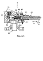
- FIG. 3 is a cross-section side view of a gas tap (6) employed in the current state of the art.
- the gas tap (6) has a tap body (65) with an internal void.
- a flow control element (64) with a recess (640) is positioned within the tap body (65).
- An inner end of the shaft (60) which is fitted horizontally within the recess (640) in a manner which permits it to advance axially extends so that it lies within the recess (640).
- the shaft (60) by means of a thruster shaft (62), applies motion to a block (68) in a channel (67) formed in the tap body (65), which provides passage to the gas.
- the end of the shaft (60) within the flow control element (64) and the thruster shaft (62) are concentrically aligned in the recess (640) within the flow control element (64).
- the thruster shaft (62) is a cylindrical structure with a projecting end.
- a spring (63) encircles the outside of an extension of the thruster shaft (62).
- a button (5) is fitted to the outward facing end of the shaft (60).
- the shaft (60) is held in such a way that it extends toward the gas tap (6) in a manner which permits it to move back and forth axially within the tap body (65) and the cover (61) which is fitted to the tap body (65). Also shown are the advancing direction D1 and the rotating direction D2 of the shaft (60).
- a pin (601) extends perpendicularly from the inner end of the shaft (60) within the flow control element (64).
- a pin (601) extending perpendicularly passes into a slot (641) formed on the flow control element (64).
- the pin (601) bearing on the walls of the slot (641), also turns the conically shaped flow control element (64).
- Behind the block (68) is positioned a magnet (69) and behind the magnet (69), a thermocouple connector (70) is positioned around the magnet (69).
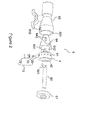
- Figure 1 shows a cross section of a gas tap (6) equipped with a tactile feedback device (2) which is the subject of the invention, with the components assembled.
- Figure 2 shows a perspective exploded view of the components of the gas tap (6) shown in Figure 1 which is the subject of the invention.
- Figure 2a shows a perspective exploded view of the tactile feedback device (2) which is the subject of the invention taken from the gas tap (6) shown in Figure 1 and Figure 2 .
- the tactile feedback device (2) includes a guide section (644) on a flow control element (64) which rotates with the rotation of the shaft (60), and a follower (3) which provides sensation of levels as it travels on the guide section (644).
- a guide section (644) is fitted on a sleeve (4) which is a separate component from the gas tap (6), and can be integrated into the gas tap (6).
- the sleeve (4) includes depressions (41) as a guide, arranged sequentially around a periphery.
- the follower (3) advances with a back and forward movement over the said depressions (41) on the periphery of the sleeve (4).
- a slot (40) cut in the intersection of the sleeve (4) permits the pin (601) on the shaft (60) to be fitted to the sleeve (4). This ensures that the pin (601), in rotating the flow control element (64), also rotates the sleeve (4).
- the sleeve (4) is positioned so that the slots (641, 40) coincide one above the other on a periphery (642) of the flow control element (64). At the same time, the sleeve (4) is accommodated within a recess (651) within the tap body (65).
- the follower (3) includes an elastic element (31) and a cylindrical element (30).
- the sequential depressions (41) on the guide section (644) may take the form of a channel, groove or peripheral projection, which fit the shape of the cylindrical element (30) or follower (3).
- One end of the cylindrical element (30) extending toward the guide section (644) is semicircular in section.
- the follower (3) is positioned so that it extends radially toward the guide section (644) and therefore toward the periphery of the sleeve (4).
- the position of the follower (3) is shown in Figures 1 and 2 .
- the follower (3) has a recessed element (32).
- the recessed element (32) has threads cut in a periphery.
- the said threads provide the attachment of the recessed element (32) to a threaded aperture (650) in the tap body (65).
- the follower (3), the elastic element (31) and the cylindrical element (30) are positioned within the recessed element (32).
- the cylindrical element (30) lies within the recessed element (32) at the level of the aperture (650) in the tap body (65).
- the button (5) which is rotated in direction D1 and direction D2 when adjusting gas flow, and turning on and turning off, also turns the shaft (60) of the gas tap (6).
- a pin (601) on the shaft (60) also turns the flow control element (64) simultaneously with the shaft (60) and also the sleeve (4) of the tactile feedback device (2).
- Gas flow adjustment or turning on and turning off is provided by the flow control element (64).
- the tactile feedback device (2) permits the levels of gas flow to be perceived by feedback according to the rotation of the shaft (60).
- a follower (3) extending radially toward the sleeve (4) and consequently toward the shaft (60), travels over depressions (41) on the sleeve (4) with the rotation of the button (5).
- the user effectively senses the level each time the follower (3) passes over the depressions (41).
- the user turns the hob on, s/he is effectively in control of the gas adjustment.
- each depression (41) forms approximately one radius of the circular end of the follower (3) which is in contact with the guide.
- the follower (3) must be supported in the forward and backward movements, which may also be described as the up and down movements, of the cylindrical element (30).
- a recessed element (32) into which the follower (3) can be located serves this purpose.
- the recessed element (32) is basically a cylindrical form with one end open and the other end closed.
- the cylindrical element (30) is in the form of a cylindrical ball, while the elastic element (31) is a spring.
- the depth of the depressions (41) may become progressively deeper.
- the user when rotating the button (5) in direction D2, will sense increasing difficulty in rotating the button (5) as the quantity of gas changes.
- the situation may be reversed and the depth of the depressions (41) may be progressively made more shallow. That is, the user, when rotating the button (5) in direction D2, will feel progressively less difficulty in rotating the button (5) as the quantity of gas changes.
- the cylindrical element (30) of the follower (3) may be a pin
- the elastic element (31) may be an elastic material which serves to project the pin and permit it to return as required.
- the depressions (41) on the guide may take the form of a circular projection.
- the diameter of the depressions (41) may be smaller than the diameter of the part of the follower (3), the cylindrical element (30), for example, with which they come into contact.
- the follower (3) may be a mechanical friction element, or a magnetic element.
- the tactile feedback device (2) may include magnetic elements.
- the guide section (644) is formed over the flow control element (64).
- REFERENCE NUMBERS 1. Cooking appliance 6. Gas tap 10. Carcass 60. Shaft 11. Front panel 601. Pin 61. Cover 2. Tactile feedback device 62. Thruster shaft 3. Follower 63. Spring 30. Cylindrical element 64. Flow control element 31. Elastic element 640. Recess 32. Recessed element 641. Slot 642. Periphery 4. Sleeve 643. Aperture 40. Slot 644. Guide section 41. Depression 65. Tap body 5. Button 650. Aperture 651. Recess D1: Advance direction 66. Entry D2: Return direction 67. Channel 68. Block 69. Magnet 70. Thermocouple connector
Abstract
Description
- The invention concerns cooker appliances equipped with a gas tap by which gas flow adjustment can be carried out manually between a minimum and a maximum value, especially gas hobs.
- Gas taps used in cooking appliances have a rotating drive shaft passing through the gas tap which adjusts the gas flow, and a flow control element entry which is coupled to the shaft. The shaft is directly connected to a button on the front panel of the gas hob. The rotating of the shaft for gas flow adjustment is provided by rotating a button.
- One of the arrangements for gas taps in the current state of the art can be seen in patent publication number
EP1672279A1 . A bar adapted so that it can slide axially on a level with the shaft in the gas tap forms the gas control element within a recess. One end of the bar presses on the second inner end of the shaft. A second end of the bar is in contact with a first conical surface which bears upon an inclined plane. The shaft partially enters the flow control element and is equipped with a first outer end into which a control button passes and a second inner end connected to the first end of the bar. There is a spring between the flow control element and the first end of the bar, and by means of the bar it pushes the shaft into an inactive axial position, pushing on the first outer end of the shaft. - Another gas tap in the current state of the art may be seen in patent publication number
US2005284519 . A manual gas tap for a cooking appliance is of the type with a conical adjustment entry which adjusts the gas flow. It is located in a central socket in the tap body and is coupled to a rotating drive shaft. A tap cover closes off the central socket. A transverse pin ensures the rotation of the rotating shaft to a two interval position which corresponds to the highest and lowest flows of gas, and to an intermediate locking position depending on the gas feed. The tap cover is in the form of a tubular bush shroud, and includes a gasket base with a sliding surface within a circular circlip with many notches on it. The circular circlip notches are in frictional contact with a transverse pin, thus creating a tactile and auditory effect. - The purpose of the invention is to provide tactile feedback in the adjustment of levels of gas flow when adjusting gas flow by rotating the gas tap of a cooker appliance. Additionally, a purpose of the invention is to provide modularity to the elements which provide tactile feedback, rendering them detachable from the gas tap.
- The invention is a cooking appliance which includes a carcass, a front panel on the carcass, a button fitted to the front panel, a flow control element which regulates gas flow by driving force provided by a shaft connected to a button, and a gas tap equipped with a tap body with hollow interior into which a flow control element is seated. The cooking appliance includes a tactile feedback device which includes a follower configured in a manner extending radially from the tap body toward the flow control element in order to provide adjustment by touch of the gas adjustment levels as the button is rotated. Additionally, a purpose of the invention is to provide modularity to the elements which provide tactile feedback, rendering them detachable from the gas tap.
- In a possible embodiment of the invention, the gas tap includes an aperture formed in the tap body in order to attach the follower to the tap body. Thus, by partially attaching the follower to the tap body, support is provided from the tap body.
- In one possible embodiment of the invention, the aperture includes threads cut into it in order to attach the follower to the tap body. Thus, the follower is attached on the tap body by rotating the threaded section into the aperture.
- In one possible embodiment of the invention, the tactile feedback device between the tap body and the flow control element includes a guide section provided on the flow control element. Thus the follower can be operated to provide a sense of tactile feedback.
- In one possible embodiment of the invention, a guide section is formed on the flow control element. This enables the follower to act on the flow control element in a manner which provides a sense of tactile feedback.
- In one possible embodiment of the invention, the tactile feedback device includes a sleeve with a guide section, formed in such a way that it encloses a periphery of the flow control element. Thus the follower can be operated on the sleeve in a manner that provides a sense of tactile feedback.
- In one possible embodiment of the invention, the guide section includes more than one sequential depression which receive the follower. In possible embodiments of the invention, the depressions can be formed as a groove, channel or projection. Thus, as the follower enters and exits the depressions in its forward and backward movements, it provides a sense of tactile feedback.
- In one possible embodiment of the invention, the depressions which are formed as a series are in the form of grooves. Thus, depressions are provided which the follower can enter and exit with ease.
- In one possible embodiment of the invention, the follower includes a cylindrical element of suitable configuration permitting it to move over the depressions. In possible embodiments of the invention, the depressions take the form of a semicircular groove, a channel or a projection, and the cylindrical element of the follower will be able to move easily over the depressions.
- In one possible embodiment of the invention, the follower includes an elastic element which permits the cylindrical element to compress and extend, and thereby move back and forth. Thus, the cylindrical element may travel a certain distance within a certain range of tolerance during level adjustment. The elastic element may be a spring or material with elastic capability.
- In one possible embodiment of the invention, the follower includes a recessed element with a recess which accommodates the cylindrical element and the elastic element. Support is thus provided for the cylindrical and elastic elements of the follower.
- In one possible embodiment of the invention, threads are formed on the recessed element in order to provide attachment to the aperture on the tap body. Thus, the recessed element can be mounted on the tap body in a manner which permits it to extend through the tap body toward the flow control element.
- In one possible embodiment of the invention, the tap body includes a recess formed on it which provides a distance gap between the tap body and a periphery of the flow control element, to accommodate a sleeve. Thus, a sleeve can be positioned within the tap body with a tolerance which permits it to turn.
- In one possible embodiment of the invention, the sleeve includes a slot which permits a pin extending from the shaft to pass into the sleeve in order to permit the shaft to turn the flow control element together with the sleeve. The slot is formed on the periphery of an internal wall of the sleeve. This ensures that the shaft rotates the sleeve. With the rotation of the sleeve, the depressions on the guide section on the sleeve rotate in the same direction. Thus, the movement of the follower is achieved in a manner which provides sensory feedback during level adjustment of the gas.
- In one possible embodiment of the invention, the flow control element includes a slot which permits a pin extending from the shaft to pass into the flow control element in order to permit the shaft to turn the flow control element. Thus the depressions on the guide section provided on the flow control element will also turn in the same direction and at the same time when the flow control element is rotated. With the rotating of the guide section on which the depressions are located, during level adjustment of the gas, the movement of the follower is achieved in a manner which provides sensory feedback.
-
Figure 1 shows a cross-section view of the assembled components of a gas tap which is the subject of the invention. -
Figure 2 shows a perspective exploded view of the components of a gas tap which is the subject of the invention. -
Figure 2a shows a perspective exploded view of the tactile feedback device which is the subject of the invention from the gas tap shown inFigure 1 andFigure 2 . -
Figure 3 is a cross-section side view of a gas tap in the current state of the art. -
Figure 4 is a perspective view from the front of a cooking apparatus with a hob fitted with the gas tap which is the subject of the invention. - The invention concerns a cooking appliance (1) which includes a gas tap (6) equipped with a tactile feedback device (2) which provides effective perception of gas flow levels when opening a gas tap (6) and adjusting the gas.
-
Figure 4 shows a perspective view from the front of a cooking apparatus (1) fitted with the gas taps (6) which are the subject of the invention, and the buttons (5) directly connected to the gas taps (6) which control the gas tap (6) which is the subject of the invention. The button (5) or buttons (5) are fitted to a front panel (11) on an accessible front face of the carcass (10) of the cooking appliance (1). The buttons (5) are fitted to the front panel (11) of the cooking appliance (1) in a manner which permits them to turn, and are directly and co-axially connected to a shaft (60) of the gas tap (6). -
Figure 3 is a cross-section side view of a gas tap (6) employed in the current state of the art. The gas tap (6) has a tap body (65) with an internal void. A flow control element (64) with a recess (640) is positioned within the tap body (65). An inner end of the shaft (60) which is fitted horizontally within the recess (640) in a manner which permits it to advance axially extends so that it lies within the recess (640). The shaft (60), by means of a thruster shaft (62), applies motion to a block (68) in a channel (67) formed in the tap body (65), which provides passage to the gas. The block (68), by reason of its position within the channel (67), determines the gas flow admitted from an entry (66) into the tap body (65). The end of the shaft (60) within the flow control element (64) and the thruster shaft (62) are concentrically aligned in the recess (640) within the flow control element (64). The thruster shaft (62) is a cylindrical structure with a projecting end. A spring (63) encircles the outside of an extension of the thruster shaft (62). A button (5) is fitted to the outward facing end of the shaft (60). The shaft (60) is held in such a way that it extends toward the gas tap (6) in a manner which permits it to move back and forth axially within the tap body (65) and the cover (61) which is fitted to the tap body (65). Also shown are the advancing direction D1 and the rotating direction D2 of the shaft (60). A pin (601) extends perpendicularly from the inner end of the shaft (60) within the flow control element (64). A pin (601) extending perpendicularly passes into a slot (641) formed on the flow control element (64). As the shaft (60) turns, the pin (601), bearing on the walls of the slot (641), also turns the conically shaped flow control element (64). Behind the block (68) is positioned a magnet (69) and behind the magnet (69), a thermocouple connector (70) is positioned around the magnet (69). -
Figure 1 shows a cross section of a gas tap (6) equipped with a tactile feedback device (2) which is the subject of the invention, with the components assembled.Figure 2 shows a perspective exploded view of the components of the gas tap (6) shown inFigure 1 which is the subject of the invention.Figure 2a shows a perspective exploded view of the tactile feedback device (2) which is the subject of the invention taken from the gas tap (6) shown inFigure 1 andFigure 2 . The tactile feedback device (2) includes a guide section (644) on a flow control element (64) which rotates with the rotation of the shaft (60), and a follower (3) which provides sensation of levels as it travels on the guide section (644). A guide section (644) is fitted on a sleeve (4) which is a separate component from the gas tap (6), and can be integrated into the gas tap (6). The sleeve (4) includes depressions (41) as a guide, arranged sequentially around a periphery. During adjustment of gas flow, the follower (3) advances with a back and forward movement over the said depressions (41) on the periphery of the sleeve (4). A slot (40) cut in the intersection of the sleeve (4) permits the pin (601) on the shaft (60) to be fitted to the sleeve (4). This ensures that the pin (601), in rotating the flow control element (64), also rotates the sleeve (4). The sleeve (4) is positioned so that the slots (641, 40) coincide one above the other on a periphery (642) of the flow control element (64). At the same time, the sleeve (4) is accommodated within a recess (651) within the tap body (65). - The follower (3) includes an elastic element (31) and a cylindrical element (30). The sequential depressions (41) on the guide section (644) may take the form of a channel, groove or peripheral projection, which fit the shape of the cylindrical element (30) or follower (3). One end of the cylindrical element (30) extending toward the guide section (644) is semicircular in section. The follower (3) is positioned so that it extends radially toward the guide section (644) and therefore toward the periphery of the sleeve (4). The position of the follower (3) is shown in
Figures 1 and2 . The follower (3) has a recessed element (32). The recessed element (32) has threads cut in a periphery. The said threads provide the attachment of the recessed element (32) to a threaded aperture (650) in the tap body (65). The follower (3), the elastic element (31) and the cylindrical element (30) are positioned within the recessed element (32). As may be seen inFigure 1 , the cylindrical element (30) lies within the recessed element (32) at the level of the aperture (650) in the tap body (65). - There follows a more detailed account of the operation of the invention. The button (5), which is rotated in direction D1 and direction D2 when adjusting gas flow, and turning on and turning off, also turns the shaft (60) of the gas tap (6). A pin (601) on the shaft (60) also turns the flow control element (64) simultaneously with the shaft (60) and also the sleeve (4) of the tactile feedback device (2). Gas flow adjustment or turning on and turning off is provided by the flow control element (64). At the same time, the tactile feedback device (2) permits the levels of gas flow to be perceived by feedback according to the rotation of the shaft (60). To this end, a follower (3) extending radially toward the sleeve (4) and consequently toward the shaft (60), travels over depressions (41) on the sleeve (4) with the rotation of the button (5). During the said travel, the user effectively senses the level each time the follower (3) passes over the depressions (41). Thus, when the user turns the hob on, s/he is effectively in control of the gas adjustment.
- In order to provide effective feedback perception between the levels of gas flow adjustment, the depth of each depression (41) forms approximately one radius of the circular end of the follower (3) which is in contact with the guide.
- The follower (3) must be supported in the forward and backward movements, which may also be described as the up and down movements, of the cylindrical element (30). A recessed element (32) into which the follower (3) can be located serves this purpose. The recessed element (32) is basically a cylindrical form with one end open and the other end closed. The cylindrical element (30) is in the form of a cylindrical ball, while the elastic element (31) is a spring.
- In alternative embodiments of the invention, the depth of the depressions (41) may become progressively deeper. Thus the user, when rotating the button (5) in direction D2, will sense increasing difficulty in rotating the button (5) as the quantity of gas changes.
- In alternative embodiments of the invention, the situation may be reversed and the depth of the depressions (41) may be progressively made more shallow. That is, the user, when rotating the button (5) in direction D2, will feel progressively less difficulty in rotating the button (5) as the quantity of gas changes.
- In another possible embodiment of the invention, the cylindrical element (30) of the follower (3) may be a pin, while the elastic element (31) may be an elastic material which serves to project the pin and permit it to return as required.
- In an alternative embodiment of the invention, in order to permit the follower (3) to travel gently over the guide, the depressions (41) on the guide may take the form of a circular projection. The diameter of the depressions (41) may be smaller than the diameter of the part of the follower (3), the cylindrical element (30), for example, with which they come into contact.
- The follower (3) may be a mechanical friction element, or a magnetic element.
- In an alternative embodiment of the invention, the tactile feedback device (2) may include magnetic elements.
- In an alternative embodiment of the invention, the guide section (644) is formed over the flow control element (64).
REFERENCE NUMBERS 1. Cooking appliance 6. Gas tap 10. Carcass 60. Shaft 11. Front panel 601. Pin 61. Cover 2. Tactile feedback device 62. Thruster shaft 3. Follower 63. Spring 30. Cylindrical element 64. Flow control element 31. Elastic element 640. Recess 32. Recessed element 641. Slot 642. Periphery 4. Sleeve 643. Aperture 40. Slot 644. Guide section 41. Depression 65. Tap body 5. Button 650. Aperture 651. Recess D1: Advance direction 66. Entry D2: Return direction 67. Channel 68. Block 69. Magnet 70. Thermocouple connector
Claims (15)
- A cooking appliance (1) which comprises a carcass (10), a front panel (11) on the carcass (10), a button (5) on the front panel (11), a flow control element (64) which regulates the flow of gas by turning a shaft (60) which is connected to the button (5) and is equipped with a gas tap (6) which has a tap body (65) with a hollow interior in which the flow control element (64) is accommodated, characterized in that the cooking appliance (1) includes a tactile feedback device (2) which includes a follower (3) configured to extend radially from the tap body (65) toward the flow control element (64) in order to provide adjustment of gas adjustment levels in a tactile manner while the button (5) is rotating.
- The cooking appliance (1) as claimed in claim 1, characterized in that the gas tap (6) includes an aperture (650) formed in the tap body (65) in order to attach a follower (3) to the tap body (65).
- The cooking apparatus (1) as claimed in claim 2, characterized in that the aperture (650) includes threads cut into it in order to attach the follower (3) to the tap body (65).
- The cooking apparatus (1) as claimed in any one of the above claims, characterized in that it includes a guide section (644) fitted to the flow control element (64) so that there is a tactile feedback device (2) between the tap body (65) and the flow control element (64).
- The cooking apparatus (1) as claimed in claim 4, characterized in that the guide section (644) is formed over the flow control element (64).
- The cooking apparatus (1) as claimed in any one of the above claims, characterized in that it includes a tactile feedback device (2), and on it a guide section (644), and a sleeve (4) formed in such a way that it encloses a periphery (642) of the flow control element (64) guide section.
- The cooking apparatus (1) as claimed in claims 5 and 6, characterized in that the guide section (644) includes more than one sequential depression (41) which receive the follower (3).
- The cooking apparatus (1) as claimed in claim 7, characterized in that the depressions (41) which are formed as a series are each in the form of a groove,
- The cooking apparatus (1) as claimed in any one of the above claims, characterized in that the follower (3) includes a cylindrical element (30) in a suitable form that permits it to travel over the depressions (41).
- The cooking apparatus (1) as claimed in any one of the above claims, characterized in that the follower (3) includes an elastic element (31) which permits the cylindrical element (30) to compress and extend, and thereby move back and forth.
- The cooking apparatus (1) as claimed in any one of the above claims, characterized in that the follower (3) includes a recessed element (32) with a recess in which the cylindrical element (30) and the elastic element (31) are positioned.
- The cooking apparatus (1) as claimed in claim 11, characterized in that the recessed element (32) includes threads so that it can be fitted to the aperture (650) on the tap body (65).
- The cooking apparatus (1) as claimed in any one of the above claims, characterized in that the tap body (65) includes a recess (651) which provides a distance gap between the tap body (65) and a periphery (642) of the flow control element (64) to accommodate the sleeve (4).
- The cooking apparatus (1) as claimed in any one of the above claims, characterized in that the sleeve (4) includes a slot (40) which permits a pin (601) extending from the shaft (60) to pass into the sleeve (4) in order to ensure that the flow control element (64) and the sleeve (4) are rotated together by the shaft (60).
- The cooking apparatus (1) as claimed in any one of the above claims, characterized in that the flow control element (64) includes a slot (641) which permits the shaft's (60) pin (601) to pass into the flow control element (64) in order to ensure that shaft (60) rotates the flow control element (64).
Priority Applications (1)
| Application Number | Priority Date | Filing Date | Title |
|---|---|---|---|
| PL14195142T PL2889539T3 (en) | 2013-12-24 | 2014-11-27 | A cooking apparatus which includes a gas tap equipped with a tactile feedback device |
Applications Claiming Priority (1)
| Application Number | Priority Date | Filing Date | Title |
|---|---|---|---|
| TR201315150 | 2013-12-24 |
Publications (2)
| Publication Number | Publication Date |
|---|---|
| EP2889539A1 true EP2889539A1 (en) | 2015-07-01 |
| EP2889539B1 EP2889539B1 (en) | 2017-01-11 |
Family
ID=51951734
Family Applications (1)
| Application Number | Title | Priority Date | Filing Date |
|---|---|---|---|
| EP14195142.6A Not-in-force EP2889539B1 (en) | 2013-12-24 | 2014-11-27 | A cooking apparatus which includes a gas tap equipped with a tactile feedback device |
Country Status (3)
| Country | Link |
|---|---|
| EP (1) | EP2889539B1 (en) |
| ES (1) | ES2617202T3 (en) |
| PL (1) | PL2889539T3 (en) |
Cited By (4)
| Publication number | Priority date | Publication date | Assignee | Title |
|---|---|---|---|---|
| CN107725867A (en) * | 2017-09-12 | 2018-02-23 | 深圳酷平方科技有限公司 | A kind of intelligent stove fire power regulator |
| CN107726376A (en) * | 2016-08-12 | 2018-02-23 | Bsh家用电器有限公司 | For the control handle equipped with gear-box for the power grade for controlling the burner in gas-cooker |
| EP3438542A1 (en) * | 2017-08-02 | 2019-02-06 | Copreci, S.Coop. | Gas valve comprising a tactile feedback device, and cooking appliance comprising said gas valve |
| FR3092638A1 (en) | 2019-02-13 | 2020-08-14 | Societe Nouvelle Sourdillon | Gas flow control valve and tap comprising such a valve |
Citations (6)
| Publication number | Priority date | Publication date | Assignee | Title |
|---|---|---|---|---|
| US2138621A (en) * | 1936-09-26 | 1938-11-29 | Imp Brass Mfg Co | Gas valve |
| US2572507A (en) * | 1948-08-18 | 1951-10-23 | Ervin H Mueller | Valve for controlling fuel gas |
| DE2101579A1 (en) * | 1971-01-14 | 1972-07-27 | Fa. Otto Egelhof, 7012 Fellbach | Actuating device for taps, in particular gas taps, with several working rotary positions |
| US20050284519A1 (en) | 2004-06-02 | 2005-12-29 | Inigo Albizuri | Gas tap for a cooking appliance, with a cover for the rotary shaft |
| EP1672279A1 (en) | 2004-12-16 | 2006-06-21 | FAGOR, S.Coop | Gas flow tap for a gas burner |
| WO2008114945A1 (en) * | 2007-03-16 | 2008-09-25 | Gi Pung Jang | Air mixing apparatus for gas range |
-
2014
- 2014-11-27 EP EP14195142.6A patent/EP2889539B1/en not_active Not-in-force
- 2014-11-27 PL PL14195142T patent/PL2889539T3/en unknown
- 2014-11-27 ES ES14195142.6T patent/ES2617202T3/en active Active
Patent Citations (6)
| Publication number | Priority date | Publication date | Assignee | Title |
|---|---|---|---|---|
| US2138621A (en) * | 1936-09-26 | 1938-11-29 | Imp Brass Mfg Co | Gas valve |
| US2572507A (en) * | 1948-08-18 | 1951-10-23 | Ervin H Mueller | Valve for controlling fuel gas |
| DE2101579A1 (en) * | 1971-01-14 | 1972-07-27 | Fa. Otto Egelhof, 7012 Fellbach | Actuating device for taps, in particular gas taps, with several working rotary positions |
| US20050284519A1 (en) | 2004-06-02 | 2005-12-29 | Inigo Albizuri | Gas tap for a cooking appliance, with a cover for the rotary shaft |
| EP1672279A1 (en) | 2004-12-16 | 2006-06-21 | FAGOR, S.Coop | Gas flow tap for a gas burner |
| WO2008114945A1 (en) * | 2007-03-16 | 2008-09-25 | Gi Pung Jang | Air mixing apparatus for gas range |
Cited By (9)
| Publication number | Priority date | Publication date | Assignee | Title |
|---|---|---|---|---|
| CN107726376A (en) * | 2016-08-12 | 2018-02-23 | Bsh家用电器有限公司 | For the control handle equipped with gear-box for the power grade for controlling the burner in gas-cooker |
| EP3438542A1 (en) * | 2017-08-02 | 2019-02-06 | Copreci, S.Coop. | Gas valve comprising a tactile feedback device, and cooking appliance comprising said gas valve |
| KR20190014446A (en) * | 2017-08-02 | 2019-02-12 | 코프레시 에스. 코오프 | Gas valve comprising a tactile feedback device, and cooking appliance comprising said gas valve |
| CN109381040A (en) * | 2017-08-02 | 2019-02-26 | 科佩西西班牙集团有限公司 | Air valve including haptic feedback devices and the cooking apparatus including the air valve |
| TWI728206B (en) * | 2017-08-02 | 2021-05-21 | 西班牙商科佩西西班牙集團有限公司 | Gas valve comprising a tactile feedback device, and cooking appliance comprising said gas valve |
| CN109381040B (en) * | 2017-08-02 | 2022-08-26 | 科佩西西班牙集团有限公司 | Gas valve comprising a tactile feedback device and cooking appliance comprising said gas valve |
| CN107725867A (en) * | 2017-09-12 | 2018-02-23 | 深圳酷平方科技有限公司 | A kind of intelligent stove fire power regulator |
| FR3092638A1 (en) | 2019-02-13 | 2020-08-14 | Societe Nouvelle Sourdillon | Gas flow control valve and tap comprising such a valve |
| EP3696463A1 (en) | 2019-02-13 | 2020-08-19 | Société Nouvelle Sourdillon | Valve for controlling a gas flow and tap comprising such a valve |
Also Published As
| Publication number | Publication date |
|---|---|
| ES2617202T3 (en) | 2017-06-15 |
| EP2889539B1 (en) | 2017-01-11 |
| PL2889539T3 (en) | 2017-04-28 |
Similar Documents
| Publication | Publication Date | Title |
|---|---|---|
| EP2889539B1 (en) | A cooking apparatus which includes a gas tap equipped with a tactile feedback device | |
| EP3087320B1 (en) | A cooking appliance which includes a gas tap equipped with a tactile feedback device | |
| KR101623795B1 (en) | cooking appliance | |
| CN109950083B (en) | Knob assembly for cooktops | |
| EP2963314A1 (en) | Shift range switching device for vehicle | |
| US20130333496A1 (en) | Adjustment Mechanism for Vehicle Seat, Vehicle Seat Comprising Such a Mechanism | |
| US20150246625A1 (en) | Hinge Mechanism and Vehicle Seat Comprising Such a Mechanism | |
| CN110017508B (en) | Knob assembly for cooktops | |
| EP3065599A1 (en) | Handheld remote control unit for electrical devices, and an electromotive furniture drive with a handheld remote control unit | |
| DE102006022326A1 (en) | Operating unit for e.g. electric kitchen stove, has rotating toggle, and housing comprising display unit at its front side for displaying adjusting information and/or operating conditions of household appliance | |
| JP2020523529A (en) | Linear actuator with external variable limit switch | |
| EP2889540B1 (en) | A cooking appliance which includes a gas tap button equipped with tactile feedback effect | |
| JP2016205746A (en) | Firepower adjusting device in gas cooking stove | |
| EP3505829A1 (en) | A cooking appliance having a control knob | |
| WO2018121951A1 (en) | Cooker device comprising a button | |
| GB2433721A (en) | Planing machine with rotary handle having locking means | |
| KR101595841B1 (en) | Caster | |
| CN103727194B (en) | Push step transmission device | |
| KR20180066512A (en) | Apparatus for skin care | |
| EP3438536B1 (en) | Valve arrangement comprising a gas valve and a tactile feedback device, and cooking appliance comprising said valve arrangement | |
| CN210535563U (en) | Household appliance controller | |
| EP2735795A1 (en) | Gas tap for a cooking appliance | |
| KR20180066515A (en) | Apparatus for skin care | |
| EP3438542B1 (en) | Gas valve comprising a tactile feedback device, and cooking appliance comprising said gas valve | |
| EP3282194B1 (en) | A control knob equipped with a gear box for controlling power level of a burner in a gas cooker |
Legal Events
| Date | Code | Title | Description |
|---|---|---|---|
| PUAI | Public reference made under article 153(3) epc to a published international application that has entered the european phase |
Free format text: ORIGINAL CODE: 0009012 |
|
| 17P | Request for examination filed |
Effective date: 20141127 |
|
| AK | Designated contracting states |
Kind code of ref document: A1 Designated state(s): AL AT BE BG CH CY CZ DE DK EE ES FI FR GB GR HR HU IE IS IT LI LT LU LV MC MK MT NL NO PL PT RO RS SE SI SK SM TR |
|
| AX | Request for extension of the european patent |
Extension state: BA ME |
|
| R17P | Request for examination filed (corrected) |
Effective date: 20160104 |
|
| RBV | Designated contracting states (corrected) |
Designated state(s): AL AT BE BG CH CY CZ DE DK EE ES FI FR GB GR HR HU IE IS IT LI LT LU LV MC MK MT NL NO PL PT RO RS SE SI SK SM TR |
|
| GRAP | Despatch of communication of intention to grant a patent |
Free format text: ORIGINAL CODE: EPIDOSNIGR1 |
|
| INTG | Intention to grant announced |
Effective date: 20160810 |
|
| GRAS | Grant fee paid |
Free format text: ORIGINAL CODE: EPIDOSNIGR3 |
|
| GRAA | (expected) grant |
Free format text: ORIGINAL CODE: 0009210 |
|
| AK | Designated contracting states |
Kind code of ref document: B1 Designated state(s): AL AT BE BG CH CY CZ DE DK EE ES FI FR GB GR HR HU IE IS IT LI LT LU LV MC MK MT NL NO PL PT RO RS SE SI SK SM TR |
|
| REG | Reference to a national code |
Ref country code: GB Ref legal event code: FG4D |
|
| REG | Reference to a national code |
Ref country code: CH Ref legal event code: EP |
|
| REG | Reference to a national code |
Ref country code: AT Ref legal event code: REF Ref document number: 861652 Country of ref document: AT Kind code of ref document: T Effective date: 20170115 |
|
| REG | Reference to a national code |
Ref country code: IE Ref legal event code: FG4D |
|
| REG | Reference to a national code |
Ref country code: DE Ref legal event code: R096 Ref document number: 602014006190 Country of ref document: DE |
|
| REG | Reference to a national code |
Ref country code: LT Ref legal event code: MG4D |
|
| REG | Reference to a national code |
Ref country code: NL Ref legal event code: MP Effective date: 20170111 |
|
| REG | Reference to a national code |
Ref country code: ES Ref legal event code: FG2A Ref document number: 2617202 Country of ref document: ES Kind code of ref document: T3 Effective date: 20170615 Ref country code: AT Ref legal event code: MK05 Ref document number: 861652 Country of ref document: AT Kind code of ref document: T Effective date: 20170111 |
|
| PG25 | Lapsed in a contracting state [announced via postgrant information from national office to epo] |
Ref country code: NL Free format text: LAPSE BECAUSE OF FAILURE TO SUBMIT A TRANSLATION OF THE DESCRIPTION OR TO PAY THE FEE WITHIN THE PRESCRIBED TIME-LIMIT Effective date: 20170111 |
|
| PG25 | Lapsed in a contracting state [announced via postgrant information from national office to epo] |
Ref country code: NO Free format text: LAPSE BECAUSE OF FAILURE TO SUBMIT A TRANSLATION OF THE DESCRIPTION OR TO PAY THE FEE WITHIN THE PRESCRIBED TIME-LIMIT Effective date: 20170411 Ref country code: LT Free format text: LAPSE BECAUSE OF FAILURE TO SUBMIT A TRANSLATION OF THE DESCRIPTION OR TO PAY THE FEE WITHIN THE PRESCRIBED TIME-LIMIT Effective date: 20170111 Ref country code: IS Free format text: LAPSE BECAUSE OF FAILURE TO SUBMIT A TRANSLATION OF THE DESCRIPTION OR TO PAY THE FEE WITHIN THE PRESCRIBED TIME-LIMIT Effective date: 20170511 Ref country code: FI Free format text: LAPSE BECAUSE OF FAILURE TO SUBMIT A TRANSLATION OF THE DESCRIPTION OR TO PAY THE FEE WITHIN THE PRESCRIBED TIME-LIMIT Effective date: 20170111 Ref country code: GR Free format text: LAPSE BECAUSE OF FAILURE TO SUBMIT A TRANSLATION OF THE DESCRIPTION OR TO PAY THE FEE WITHIN THE PRESCRIBED TIME-LIMIT Effective date: 20170412 Ref country code: HR Free format text: LAPSE BECAUSE OF FAILURE TO SUBMIT A TRANSLATION OF THE DESCRIPTION OR TO PAY THE FEE WITHIN THE PRESCRIBED TIME-LIMIT Effective date: 20170111 |
|
| PG25 | Lapsed in a contracting state [announced via postgrant information from national office to epo] |
Ref country code: RS Free format text: LAPSE BECAUSE OF FAILURE TO SUBMIT A TRANSLATION OF THE DESCRIPTION OR TO PAY THE FEE WITHIN THE PRESCRIBED TIME-LIMIT Effective date: 20170111 Ref country code: LV Free format text: LAPSE BECAUSE OF FAILURE TO SUBMIT A TRANSLATION OF THE DESCRIPTION OR TO PAY THE FEE WITHIN THE PRESCRIBED TIME-LIMIT Effective date: 20170111 Ref country code: BG Free format text: LAPSE BECAUSE OF FAILURE TO SUBMIT A TRANSLATION OF THE DESCRIPTION OR TO PAY THE FEE WITHIN THE PRESCRIBED TIME-LIMIT Effective date: 20170411 Ref country code: PT Free format text: LAPSE BECAUSE OF FAILURE TO SUBMIT A TRANSLATION OF THE DESCRIPTION OR TO PAY THE FEE WITHIN THE PRESCRIBED TIME-LIMIT Effective date: 20170511 Ref country code: AT Free format text: LAPSE BECAUSE OF FAILURE TO SUBMIT A TRANSLATION OF THE DESCRIPTION OR TO PAY THE FEE WITHIN THE PRESCRIBED TIME-LIMIT Effective date: 20170111 Ref country code: SE Free format text: LAPSE BECAUSE OF FAILURE TO SUBMIT A TRANSLATION OF THE DESCRIPTION OR TO PAY THE FEE WITHIN THE PRESCRIBED TIME-LIMIT Effective date: 20170111 |
|
| REG | Reference to a national code |
Ref country code: DE Ref legal event code: R097 Ref document number: 602014006190 Country of ref document: DE |
|
| PG25 | Lapsed in a contracting state [announced via postgrant information from national office to epo] |
Ref country code: RO Free format text: LAPSE BECAUSE OF FAILURE TO SUBMIT A TRANSLATION OF THE DESCRIPTION OR TO PAY THE FEE WITHIN THE PRESCRIBED TIME-LIMIT Effective date: 20170111 Ref country code: SK Free format text: LAPSE BECAUSE OF FAILURE TO SUBMIT A TRANSLATION OF THE DESCRIPTION OR TO PAY THE FEE WITHIN THE PRESCRIBED TIME-LIMIT Effective date: 20170111 Ref country code: CZ Free format text: LAPSE BECAUSE OF FAILURE TO SUBMIT A TRANSLATION OF THE DESCRIPTION OR TO PAY THE FEE WITHIN THE PRESCRIBED TIME-LIMIT Effective date: 20170111 Ref country code: EE Free format text: LAPSE BECAUSE OF FAILURE TO SUBMIT A TRANSLATION OF THE DESCRIPTION OR TO PAY THE FEE WITHIN THE PRESCRIBED TIME-LIMIT Effective date: 20170111 |
|
| PLBE | No opposition filed within time limit |
Free format text: ORIGINAL CODE: 0009261 |
|
| STAA | Information on the status of an ep patent application or granted ep patent |
Free format text: STATUS: NO OPPOSITION FILED WITHIN TIME LIMIT |
|
| REG | Reference to a national code |
Ref country code: FR Ref legal event code: PLFP Year of fee payment: 4 |
|
| PG25 | Lapsed in a contracting state [announced via postgrant information from national office to epo] |
Ref country code: DK Free format text: LAPSE BECAUSE OF FAILURE TO SUBMIT A TRANSLATION OF THE DESCRIPTION OR TO PAY THE FEE WITHIN THE PRESCRIBED TIME-LIMIT Effective date: 20170111 Ref country code: SM Free format text: LAPSE BECAUSE OF FAILURE TO SUBMIT A TRANSLATION OF THE DESCRIPTION OR TO PAY THE FEE WITHIN THE PRESCRIBED TIME-LIMIT Effective date: 20170111 |
|
| 26N | No opposition filed |
Effective date: 20171012 |
|
| PG25 | Lapsed in a contracting state [announced via postgrant information from national office to epo] |
Ref country code: SI Free format text: LAPSE BECAUSE OF FAILURE TO SUBMIT A TRANSLATION OF THE DESCRIPTION OR TO PAY THE FEE WITHIN THE PRESCRIBED TIME-LIMIT Effective date: 20170111 |
|
| PG25 | Lapsed in a contracting state [announced via postgrant information from national office to epo] |
Ref country code: MC Free format text: LAPSE BECAUSE OF FAILURE TO SUBMIT A TRANSLATION OF THE DESCRIPTION OR TO PAY THE FEE WITHIN THE PRESCRIBED TIME-LIMIT Effective date: 20170111 |
|
| PG25 | Lapsed in a contracting state [announced via postgrant information from national office to epo] |
Ref country code: CH Free format text: LAPSE BECAUSE OF NON-PAYMENT OF DUE FEES Effective date: 20171130 Ref country code: LI Free format text: LAPSE BECAUSE OF NON-PAYMENT OF DUE FEES Effective date: 20171130 |
|
| PG25 | Lapsed in a contracting state [announced via postgrant information from national office to epo] |
Ref country code: LU Free format text: LAPSE BECAUSE OF NON-PAYMENT OF DUE FEES Effective date: 20171127 |
|
| REG | Reference to a national code |
Ref country code: BE Ref legal event code: MM Effective date: 20171130 |
|
| REG | Reference to a national code |
Ref country code: IE Ref legal event code: MM4A |
|
| PG25 | Lapsed in a contracting state [announced via postgrant information from national office to epo] |
Ref country code: MT Free format text: LAPSE BECAUSE OF NON-PAYMENT OF DUE FEES Effective date: 20171127 |
|
| PG25 | Lapsed in a contracting state [announced via postgrant information from national office to epo] |
Ref country code: IE Free format text: LAPSE BECAUSE OF NON-PAYMENT OF DUE FEES Effective date: 20171127 |
|
| PG25 | Lapsed in a contracting state [announced via postgrant information from national office to epo] |
Ref country code: BE Free format text: LAPSE BECAUSE OF NON-PAYMENT OF DUE FEES Effective date: 20171130 |
|
| PGFP | Annual fee paid to national office [announced via postgrant information from national office to epo] |
Ref country code: PL Payment date: 20181116 Year of fee payment: 5 Ref country code: DE Payment date: 20181130 Year of fee payment: 5 |
|
| PGFP | Annual fee paid to national office [announced via postgrant information from national office to epo] |
Ref country code: IT Payment date: 20181122 Year of fee payment: 5 Ref country code: FR Payment date: 20181123 Year of fee payment: 5 Ref country code: ES Payment date: 20181218 Year of fee payment: 5 |
|
| PG25 | Lapsed in a contracting state [announced via postgrant information from national office to epo] |
Ref country code: HU Free format text: LAPSE BECAUSE OF FAILURE TO SUBMIT A TRANSLATION OF THE DESCRIPTION OR TO PAY THE FEE WITHIN THE PRESCRIBED TIME-LIMIT; INVALID AB INITIO Effective date: 20141127 |
|
| GBPC | Gb: european patent ceased through non-payment of renewal fee |
Effective date: 20181127 |
|
| PG25 | Lapsed in a contracting state [announced via postgrant information from national office to epo] |
Ref country code: CY Free format text: LAPSE BECAUSE OF FAILURE TO SUBMIT A TRANSLATION OF THE DESCRIPTION OR TO PAY THE FEE WITHIN THE PRESCRIBED TIME-LIMIT Effective date: 20170111 |
|
| PG25 | Lapsed in a contracting state [announced via postgrant information from national office to epo] |
Ref country code: MK Free format text: LAPSE BECAUSE OF FAILURE TO SUBMIT A TRANSLATION OF THE DESCRIPTION OR TO PAY THE FEE WITHIN THE PRESCRIBED TIME-LIMIT Effective date: 20170111 |
|
| PG25 | Lapsed in a contracting state [announced via postgrant information from national office to epo] |
Ref country code: GB Free format text: LAPSE BECAUSE OF NON-PAYMENT OF DUE FEES Effective date: 20181127 |
|
| PG25 | Lapsed in a contracting state [announced via postgrant information from national office to epo] |
Ref country code: TR Free format text: LAPSE BECAUSE OF FAILURE TO SUBMIT A TRANSLATION OF THE DESCRIPTION OR TO PAY THE FEE WITHIN THE PRESCRIBED TIME-LIMIT Effective date: 20170111 |
|
| REG | Reference to a national code |
Ref country code: DE Ref legal event code: R119 Ref document number: 602014006190 Country of ref document: DE |
|
| PG25 | Lapsed in a contracting state [announced via postgrant information from national office to epo] |
Ref country code: AL Free format text: LAPSE BECAUSE OF FAILURE TO SUBMIT A TRANSLATION OF THE DESCRIPTION OR TO PAY THE FEE WITHIN THE PRESCRIBED TIME-LIMIT Effective date: 20170111 |
|
| PG25 | Lapsed in a contracting state [announced via postgrant information from national office to epo] |
Ref country code: DE Free format text: LAPSE BECAUSE OF NON-PAYMENT OF DUE FEES Effective date: 20200603 Ref country code: FR Free format text: LAPSE BECAUSE OF NON-PAYMENT OF DUE FEES Effective date: 20191130 Ref country code: IT Free format text: LAPSE BECAUSE OF NON-PAYMENT OF DUE FEES Effective date: 20191127 |
|
| REG | Reference to a national code |
Ref country code: ES Ref legal event code: FD2A Effective date: 20210527 |
|
| PG25 | Lapsed in a contracting state [announced via postgrant information from national office to epo] |
Ref country code: ES Free format text: LAPSE BECAUSE OF NON-PAYMENT OF DUE FEES Effective date: 20191128 |
|
| PG25 | Lapsed in a contracting state [announced via postgrant information from national office to epo] |
Ref country code: PL Free format text: LAPSE BECAUSE OF NON-PAYMENT OF DUE FEES Effective date: 20191127 |